EP0836835A2 - Spinal implant fixation - Google Patents
Spinal implant fixationDownload PDFInfo
- Publication number
- EP0836835A2 EP0836835A2EP97308140AEP97308140AEP0836835A2EP 0836835 A2EP0836835 A2EP 0836835A2EP 97308140 AEP97308140 AEP 97308140AEP 97308140 AEP97308140 AEP 97308140AEP 0836835 A2EP0836835 A2EP 0836835A2
- Authority
- EP
- European Patent Office
- Prior art keywords
- rod
- seat
- insert
- locking
- assembly
- Prior art date
- Legal status (The legal status is an assumption and is not a legal conclusion. Google has not performed a legal analysis and makes no representation as to the accuracy of the status listed.)
- Withdrawn
Links
- 239000007943implantSubstances0.000titleclaimsabstractdescription15
- 210000000988bone and boneAnatomy0.000claimsabstractdescription46
- 238000000034methodMethods0.000claimsabstractdescription16
- 230000007246mechanismEffects0.000abstractdescription32
- 230000008878couplingEffects0.000description8
- 238000010168coupling processMethods0.000description8
- 238000005859coupling reactionMethods0.000description8
- 238000003780insertionMethods0.000description7
- 230000037431insertionEffects0.000description7
- 230000000712assemblyEffects0.000description5
- 238000000429assemblyMethods0.000description5
- 239000000463materialSubstances0.000description4
- 210000003484anatomyAnatomy0.000description3
- RTAQQCXQSZGOHL-UHFFFAOYSA-NTitaniumChemical compound[Ti]RTAQQCXQSZGOHL-UHFFFAOYSA-N0.000description2
- 230000002159abnormal effectEffects0.000description2
- 238000012937correctionMethods0.000description2
- 238000012986modificationMethods0.000description2
- 230000004048modificationEffects0.000description2
- 230000002093peripheral effectEffects0.000description2
- 239000004033plasticSubstances0.000description2
- 229920003023plasticPolymers0.000description2
- 239000007787solidSubstances0.000description2
- 229910052719titaniumInorganic materials0.000description2
- 239000010936titaniumSubstances0.000description2
- 238000013519translationMethods0.000description2
- 206010061246Intervertebral disc degenerationDiseases0.000description1
- 238000005299abrasionMethods0.000description1
- 239000000956alloySubstances0.000description1
- 229910045601alloyInorganic materials0.000description1
- 150000001721carbonChemical class0.000description1
- 239000002131composite materialSubstances0.000description1
- 208000018180degenerative disc diseaseDiseases0.000description1
- 238000002059diagnostic imagingMethods0.000description1
- 238000002513implantationMethods0.000description1
- 230000006872improvementEffects0.000description1
- 238000007373indentationMethods0.000description1
- 208000021600intervertebral disc degenerative diseaseDiseases0.000description1
- 210000004705lumbosacral regionAnatomy0.000description1
- 230000013011matingEffects0.000description1
- 239000000203mixtureSubstances0.000description1
- HLXZNVUGXRDIFK-UHFFFAOYSA-Nnickel titaniumChemical compound[Ti].[Ti].[Ti].[Ti].[Ti].[Ti].[Ti].[Ti].[Ti].[Ti].[Ti].[Ni].[Ni].[Ni].[Ni].[Ni].[Ni].[Ni].[Ni].[Ni].[Ni].[Ni].[Ni].[Ni].[Ni]HLXZNVUGXRDIFK-UHFFFAOYSA-N0.000description1
- 229910001000nickel titaniumInorganic materials0.000description1
- 230000000399orthopedic effectEffects0.000description1
- 230000008569processEffects0.000description1
- 230000000750progressive effectEffects0.000description1
- 230000000717retained effectEffects0.000description1
- 230000002441reversible effectEffects0.000description1
- 206010039722scoliosisDiseases0.000description1
- 208000005198spinal stenosisDiseases0.000description1
- 230000006641stabilisationEffects0.000description1
- 238000011105stabilizationMethods0.000description1
- 239000010935stainless steelSubstances0.000description1
- 229910001220stainless steelInorganic materials0.000description1
- 238000001356surgical procedureMethods0.000description1
- 238000012800visualizationMethods0.000description1
Images


Classifications
- A—HUMAN NECESSITIES
- A61—MEDICAL OR VETERINARY SCIENCE; HYGIENE
- A61B—DIAGNOSIS; SURGERY; IDENTIFICATION
- A61B17/00—Surgical instruments, devices or methods
- A61B17/56—Surgical instruments or methods for treatment of bones or joints; Devices specially adapted therefor
- A61B17/58—Surgical instruments or methods for treatment of bones or joints; Devices specially adapted therefor for osteosynthesis, e.g. bone plates, screws or setting implements
- A61B17/68—Internal fixation devices, including fasteners and spinal fixators, even if a part thereof projects from the skin
- A61B17/70—Spinal positioners or stabilisers, e.g. stabilisers comprising fluid filler in an implant
- A61B17/7001—Screws or hooks combined with longitudinal elements which do not contact vertebrae
- A61B17/7035—Screws or hooks, wherein a rod-clamping part and a bone-anchoring part can pivot relative to each other
- A61B17/7037—Screws or hooks, wherein a rod-clamping part and a bone-anchoring part can pivot relative to each other wherein pivoting is blocked when the rod is clamped
- A—HUMAN NECESSITIES
- A61—MEDICAL OR VETERINARY SCIENCE; HYGIENE
- A61B—DIAGNOSIS; SURGERY; IDENTIFICATION
- A61B17/00—Surgical instruments, devices or methods
- A61B17/56—Surgical instruments or methods for treatment of bones or joints; Devices specially adapted therefor
- A61B17/58—Surgical instruments or methods for treatment of bones or joints; Devices specially adapted therefor for osteosynthesis, e.g. bone plates, screws or setting implements
- A61B17/68—Internal fixation devices, including fasteners and spinal fixators, even if a part thereof projects from the skin
- A61B17/70—Spinal positioners or stabilisers, e.g. stabilisers comprising fluid filler in an implant
- A61B17/7001—Screws or hooks combined with longitudinal elements which do not contact vertebrae
- A61B17/7032—Screws or hooks with U-shaped head or back through which longitudinal rods pass
Definitions
- the present inventionrelates to a implant fixation system and locking mechanism. More particularly, the present invention provides a locking mechanism, which can be multi-planar or fixed, for securing a rod to an implant.
- Stabilization of the spine for various conditionsincluding degenerative disc disease, scoliosis, spondylolithises and spinal stenosis often require attaching implants to the spine and then securing the implants to spinal rods.
- spinal fixation devicescan immobilize the vertebrae and can alter the alignment of the spine over a large number of vertebrae by means of connecting at least one elongate rod to the sequence of selected vertebrae.
- Such rodscan span a large number of vertebrae, such as three or four.
- the spine anatomyrarely allows for three or more implants to be directly in line.
- the rodIn order to allow for this irregularity, the rod must be contoured to the coronal plane. With anatomical curvature in the saggital plane found in the lumbar spine, the rod has to be contoured in both planes, requiring considerable effort and surgical time.
- the U.S. Patents 5,554,157, issued September 10, 1996, 5,549,608 issued August 27, 1996, and 5,586,984 issued December 24, 1996, all to Errico et al.disclose polyaxial locking screw and coupling element devices for use with rod fixation apparatus.
- the '157 patentdiscloses a coupling element including an interior axial passage having an interior surface which is inwardly curvate at the lower portion thereof such that it comprises a socket for polyaxially retaining a spherical head of a screw.
- the coupling elementfurther includes a pair of vertically oriented opposing channels extending down from the top of the coupling element which define therebetween a rod receiving seat.
- the channelfurther provides the walls of the upper portion to a pair of upwardly extending members, each including an exterior threading disposed on the upper most portion thereof for receiving a locking nut.
- the locking nutseats against the top of the rod which in turn seats on top of the screw head. The nut causes the rod to be locked between the nut and screw and the screw to be locked in the socket.
- the '608 patentdiscloses a modification wherein a locking ring is disposed about the exterior of the lower portion of the coupling element and provides an inward force on an outwardly tapered portion upon downward translation thereof causing the interior chamber to crush lock a screw head therein to eliminate the polyaxial nature of the screw element coupling.
- the '984 patentdiscloses a polyaxial orthopedic device including a cutter element having a tapered lower portion including a slotted interior chamber in which a curvated head of a screw is initially polyaxialed disposed.
- the coupling elementincludes a recessed for receiving a rod of the implant apparatus.
- a locking ringis disposed about the lower portion of the coupling element and provides an inward force on the outwardly tapered portion upon downward translation thereof. The vertical slots are caused to close and crush and thereby locking the screw head within the inter chamber thereof.
- the locking mechanismlocks both the rod and screw head simultaneously.
- No prior art patentallows for the spherical head of the screw to be locked at a desired angle prior to rod insertion.
- the only surface locking the rod in placeis the surface between either the seat and a locking nut or the rod entrapped between a locking ring and the seat.
- a spinal implant fixation assemblyincluding bone fixation means for fixation to a bone and rod receiving means operatively connected to the bone fixation means.
- the rod receiving meansincludes a first seat having an inner wall for seating a portion of a rod therein.
- the assemblyfurther provides locking means engaging the rod receiving means for forcing the inner wall to contour around and engage the rod seated therein and for locking and fixing the rod relative to the inner housing.
- the present inventionfurther provides a method for locking a rod to a bone by the steps of fixing a rod seating member to a bone and then seating a portion of a rod within a substantially U-shaped seat of the seating member.
- the rodis locked within the U-shaped seat while engaging in contouring at least a portion of the U-shaped seat about the rod.
- the present inventionfurther provides a spinal fixation assembly including screw head receiving means for retaining a head of a screw therein.
- the screw head receiving meansis moveable within the assembly between a locked position entrapping the screw head and an unlocked position wherein the screw head enters or escapes.
- a methodis furthcr provided for retaining a screw head in a spinal fixation assembly by inserting a screw head into an expanded pocket of an insert contained within a first portion of an internal portion of a body member wherein the internal portion includes the first portion which is radially outwardly recessed relative to a second portion and then moving the insert into the second portion which compresses the pocket of the insert into a contracted condition to fixedly engage the screw head within the pocket.
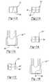
- a spinal implant fixation assembly constructed in accordance with the present inventionis generally shown at 10 in Figure 1. Similar structures amongst the several embodiments are shown by primed numbers in the various Figures.
- the assembly 10includes a bone fixation element generally shown at 12 for fixation of the assembly 10 to a bone.
- a rod receiving mechanismis generally shown at 14 and is operatively connected to the bone fixation element 12.
- the rod receiving mechanism 14includes a seat 16 having an inner wall 18 for seating a portion of a rod 20 therein.
- a locking mechanismgenerally shown at 22 engages the rod receiving mechanism 14 for forcing the inner wall 18 to contour around and engage the rod 20 seated therein and for locking and fixing the rod 20 relative to the assembly 10.
- the rod receiving mechanism 14includes a tapered outer surface 24. As shown in the several embodiments, this outer surface 24 can be threaded. However, other means for securing the locking mechanism 22 can be used to achieve the same results.
- the locking mechanism 22is in the form of a nut member 26 having an inner surface 28, which can be threaded for use with the threaded outer surface 24 of the rod receiving mechanism 14, for being forced over and engaging the outer surface 24 and inwardly deflecting the rod receiving mechanism 14 about the seat portion 16 as the locking member 26 further engages the tapered outer surface 14.
- the rod receiving mechanism 14includes a body portion 30 having two arms 32,34 extending therefrom and being substantially parallel relative to each other.
- the two arms 32,34 and the body portion 30form a U-shaped inner surface defining the seat portion 16 thereof.
- the arms 32,34have the tapered threaded surface 24 about the outer surface thereof.
- the tapered threaded portion 24 in combination with the nut member 26provide a self-locking mechanism for securing the rod 20 thereto.
- self-lockingit is meant that mere threading of the nut member 26 on the tapered surface 24 locks the nut member 26 in place.
- This locking mechanismis vibration resistant and has not been previously used in spinal implants.
- the self-locking mechanismprovides convenience of use and secure locking of the system along with flexibility of attachment of the rod and implant.
- the bone fixation mechanism 12is shown as a screw portion 36 extending integrally from the body portion 30.
- the body portion 30includes a longitudinal axis.
- the bone fixation element 12, whether it is a screw portion as shown in Figure 1 at 36 or a hook portion 38 as shown in Figure 2,can either 1) lie along the axis so as to define a substantially linear element or 2) be angled relative to the longitudinal axis of the body portion 30. In this manner, the device can be adapted to various angulations between the bone connection surface and the rod 20.
- These embodiments of the inventionprovide either a thread or hook portion 36,38, respectively, having the upper tapered threaded portion about the U-shaped seat 16. Variability of angulation is eliminated as each unit would be a solid fix piece. But the assemblies can be individually made in various angulations. Such assemblies provide solid fixation of implants to the rod 20 where angulation is either not required or where known angulation may be repeatedly needed.
- the bone fixation element 12can take on various shapes and sizes known in the art.
- the element 12can have various configurations as a screw 36 and various thread designs.
- the hook portion 38can be manufactured and used in a variety of hook sizes. Other shapes and sizes well known in the art can also be used.
- the assemblyis preferably made from machined titanium or alloy, but can be alternatively made from other types of cast or molded materials well known in the art.
- FIG. 3A second alternative embodiment of the present invention is shown in Figures 3 and 4. As stated above, double primed numbers are used to indicate like structure between the several embodiments.
- the bone fixation element 12"is shown as an independent screw member.
- the element 12"includes a head portion 40 having a substantially spherical outer surface 42.
- the rod receiving mechanism 14"is shown as a single integral unit including the first seat 16" for receiving the rod member 20" as discussed above between the arms 32" and 34" and a second seating surface 44 having a substantially spherical shape for seating the head portion 40 of element 12" therein.
- the rod receiving member 14it consists of a substantially tubular body including the pair of spaced substantially parallel arms 32",34" extending therefrom and forming the substantially U-shaped seat 16" as discussed above.
- the tubular bodyfurther includes a socket portion defining the second seat 44 which includes outwardly flaring flanges 46, as best shown in Figure 3.
- the outwardly flaring flanges 46have distal ends which flare radially outwardly relative to a central axis of the rod receiving member 14.
- the outer surfaces 50define the outer surface of the second seat 44.
- the head portion 40 and/or the seat 44can have a textured surface for better gripping of the spherical outer surface 42.
- the textural surfacecan take on various forms, such as ripples abrasions or the like, which increase the effective surface to surface contact and provide micro or macro grips against the outer surface 42.
- the locking mechanism 22" of this embodimentincludes the nut member 26" and a tubular sleeve member generally shown at 52.
- the nut member 26" and sleeve member 52are shown as separate elements, the present invention could be practiced where the nut member 26" includes a skirt portion integrally extending therefrom. In either embodiment, the sleeve 52 locks and fixes the head portion 40 of the screw element 12" within the seat 44 prior to the nut member 26" locking and fixing the rod 20" within the seat 16".
- the sleeve member 52includes an inner surface 54 which, upon being disposed over and about the outer surface 50 of the flanges 46, engages and inwardly deflects the distally outwardly tapering surfaces thereof to engage the socket portion of the seat 44 with the head portion 40 of the screw member 12". This can be accomplished prior to the connection of member 14" with the rod 20" and its locking in place by the nut member 26".
- the sleeve member 52includes curved recessed portions 54 for seating of the rod member 20" therein in the assembled configuration as shown in Figure 4.
- the sleeve 52also includes a skirt portion 56 which is disposed about the flanges 46 in the assembled position, as shown in Figure 4.
- the element 30"includes the tapered threaded outer surface 24" which can be engaged by the threaded inner surface 28" of the nut member 26".
- This locking of thc screw elementcan occur in two ways.
- the outer sleeve 52can be pushed down with an instrument without the rod being in place or pushed down as the nut 26" is tightened over the rod 20". This gives the surgeon the option of adjusting the screw angle for abnormal anatomy and locking it prior to locking the rod 20" to the assembly 10" or, alternatively, locking the screw element 12" and rod 20" interfaces simultaneously when correction is not required.
- the head portion 40is shown to be substantially spherical in shape.
- the seat 44is a socket portion which is also substantially spherical for seating and engaging the head portion 40 therein. This allows for easy angular adjustment between the two components.
- the head portion 40 of the screw element 12"can take on various other shapes, such as a square shape, which may not allow for similar angulation but would allow for similar connection between the head portion 40 and the seat 44 in accordance with the present invention.
- the configurationallows for up to 25° or more of angulation in all directions relative to the shaft portion 58 of the screw element 12".
- the present inventionprovides a multi-planar locking mechanism that allows for angulation in all planes. It also provides a locking mechanism that allows the mechanism to be locked at any angle prior to rod insertion. Further results of the above is that the invention provides a multi-planar locking mechanism that reduces intraoperative rod contouring provides flexibility.
- the sleeve ring 52includes an edge surface 58.
- the nut member 26"includes an abutment surface 60 for abutting against the edge 58 as the nut member 26" is threaded onto the tapered threaded portion 24" to force the ring member 52 over the outer surface of the flanges 50.
- the screw element 12"is fixed onto a bone, the head portion 40 extending from the bone surface.
- the rod seating member 14"is then disposed over the head portion 40 of the screw element 12" by insertion of the head portion 40 into the seat 44. This is a snapping operation but allows for angular adjustment of the tubular member 14" relative to the longitudinal axis of the screw element 12".
- the ring 52is then disposed over the member 14" and an instrument is used to force the ring member 52 over the flanges 50 so as to lock the head portion 40 within the seat 44 thereby fixing the angulation between the two elements.
- the rod 20"is then seated within seat 16" of the member 14" as well as within the groove 54 of the ring 52.
- the nut member 26"is threaded over the tapered outer surface 24" of the arms 32",34" thereby fixing the rod 20" in frictional engagement within the seat 16" and against the nut member 26".
- the nut member 26"can be used to force the sleeve member 52 in place so as to lock the head 40 and screw member 12" relative to the element 14".
- the present inventionprovides a method for locking a rod 20, 20" to a bone by the general steps of first fixing a rod seating member 14,14',14" to a bone and then seating a portion of the rod 20,20" within a substantially U-shaped seat 16,16" of the seating member 14,14',14".
- the rod 20,20"is locked within the U-shaped seat 16,16" while engaging and contouring at least a portion of the U-shaped seat 16,16" about the rod 20,20".
- this methodcan be more specifically defined by the steps of fixing the bone fixation member 12" to a bone and then locking and fixing the rod seating member 14" to the head portion 40 of the bone fixation member 12" and then locking the rod 20" within the U-shaped seat 16".
- the fixing stepis accomplished by forcing the ring 52 over the outwardly flared portions 46 of the seat portion 44 to lock and fix the head portion 40 of the bone fixation element 12" therein.
- the locking of the rodis accomplished by locking the rod 20" within the U-shaped seat 16" by engaging the inner threaded surface 28" of the nut member 26" over the tapered outer threaded surface 24" of the U-shaped seat 16" to force the ring 52 over the outer surface 50 of the seat portion 44 to lock and fix the head portion 40 of the bone fixation element 12" therein while simultaneously deforming the inner surface of the U-shaped seat 16" about the rod 20" seated therein.
- FIG. 5-8A further embodiment of the present invention is shown in Figures 5-8.
- This embodiment of the inventionincludes the bone fixation element generally shown at 12"", this embodiment being characterized by including a screw head receiving insert generally shown at 70 which is moveable within the assembly 10"" between a locked position as shown in Figures 7 and 8 entrapping the screw head 40"" therein and an unlocked position wherein the screw head 40"" enters or escapes, as shown in Figures 5 and 6. That is, this embodiment of the invention includes a single unit capable of receiving a screw head 40"" therein and then allowing for polyaxial adjustment of the screw head relative to the assembly and then locking of the screw head within the assembly without requirement of additional elements to the assembly.
- This embodiment of the inventiondrastically reduces surgical time in spinal surgery and simplifies the elements needed for implementing the bone fixation. Such a system is particularly useful when the rod 20"" in not lined up with the screw 12"".
- the assembly 10""includes a body 30"" including an internal portion 72"".
- the internal portion 12"generally includes a first portion 74 which is radially outwardly recessed relative to a second internal portion 76.
- the internal portion 74can be effectively recessed or actually recessed.
- the first portioncould have a greater diameter than the second portion or the second portion could be formed by flanges that extend radially internally from an inner surface of the second portion thereby effectively defining the end of each flange as the radially inwardly extending surface.
- the screw head receiving means 70consists of a insert member 70 including a seat 44"" for seating the screw head 40"" therein.
- the insert 70is moveable within the internal portion 72 between the locked and unlocked position as discussed below.
- FIG 9shows an enlarged cross-sectional view of the insert 70 made in accordance with the present invention.
- the seat 44""more particularly includes a base portion 78 and a plurality of flexible arms 80 extending therefrom combining with the base portion 78 to form a pocket.
- the arms 80define flexible walls of the pocket extending from the base portion 78.
- As least one of the arms 80includes a hinged portion 82 allowing for outward deflection of the arm 80.
- the hinged portionas shown in Figure 9, can be a recess cut into the base portion 78 adjacent the arm 80 to allow for increase outward flexibility of the arm 80 which includes the hinged portion 82. This allows for increased ease of insertion of the screw head 40"" into the pocket.
- FIGs 5-8sequentially show the method of using the present invention for fixing a polyaxial screw 12"" therein.
- the screw itself 12""is inserted into the bone by itself. This provides excellent visualization of screw placement since the larger body/insert assembly 10"" is pushed on the screw head after screw insertion into the bone.
- the insert 70is sufficiently collapsible to be snapped into the internal portion 72 of the body element 34"". This is accomplished by compressing the insert 70 and releasing it inside the internal portion 72.
- the assemblyitself can be made from any durable material, such as carbon composites, nitinol, stainless steel, composite materials, plastics and plastic compositions or even resorbable materials.
- titaniumis used to minimize artifacts from x-rays and other diagnostic imaging systems.
- the combined assemblyeffectively provides the equivalent of a one piece assembly which is a significant improvement over prior art two piece assemblies or multiple piece assemblies necessary for only securing a screw head within a fixation device.
- Lockingcan be achieved in two manners.
- the body 30""can be pulled up relative to the screw 12"" with an instrument (not shown) without the rod 20"" being in placed or pulled by the nut 26"” as the nut 26"" is tightened over the rod 20"".
- Thisprovides the surgeon with the option of adjusting the screw angle for abnormal anatomy and locking it prior to locking the rod 20"" to the assembly 10"" or locking the screw 12"" and rod 20"” interfaces simultaneously when correction is not required.
- the U-shaped inner surface defining the seat portion 16""extends into the internal portion 72.
- the inserted portion of the rod 20"contacts a portion of the surface of the base portion 80 of the insert 70 for final seating of the insert 70 within the second portion 76 of the internal portion 72.
- the second portion 76includes a radially inwardly tapering surface.
- the nut 26"which includes a tapered treaded internal surface as discussed above, compresses the tapered threaded portion 14"" of the assembly 10"" against the rod 20"".
- the nut 26""will also seat against the rod 20"", but the surface area engaging the rod 20"" will be vastly increased over the prior art, which increases the assembly to rod holding power.
- the nut against the rodis only a secondary locking means.
- the force of the portions 14"" against the rod 20"”is the primary locking mechanism.
- the rod 20"is engaged by the nut 26"", the body portion 30"", and the insert 70. Effective engagement of the insert 70 is significant as demonstrated in Figures 11 and 12.
- Figure 11shows a cross section of the assembly wherein a straight rod 20 is retained within the assembly.
- the rod 20will push the insert 70 down until the rod 20 fits within the U-shaped channel of the body 30"". It is ideal for the rod 20 to contact the edges of the body 30"" inside the U-shaped channel for maximum rod gripping strength.
- the insert 70 of the present embodimentcan self-adjust and be pushed downward further then the edges of the body 30"" within the U-shaped cut-out to maximize rod contact.
- Such self adjustmentis not at all found in the prior art since such U-shaped cut-outs in a body portion are fixed machine surfaces.
- Figures 13-18shown various permutations of the insert and body portions of the present invention.
- Figure 13shows an insert 70 including arms 80 having smooth outside surfaces. This is an embodiment which is shown in the previously discussed figures.
- the insert 70"includes arms 80" having an stepped outer surface 82. Such a step outer surface provides a stop for engaging the inner surface of the internal portion 72 to prevent the insert 70" from moving beyond the desired engagement location.
- Figure 16shows an insert 70" including a radially inwardly tappered outer surface portion 84 for progressive engagement with the second portion 72.
- Figure 17shows a further embodiment of the insert 70" combining the inward tappered surface 84" with the step 82".
- Figure 15shows a body portion 30"" wherein the second portion 76 includes a radially inwardly extending lip 86 at the peripheral edge thereof.
- Figure 18shows a chamfered surface 88 a the peripheral edge of the second portion 76. both the lip 86 or the chamfered portion 88 provide further stops to ensure that once the insert member 70 is disposed within the internal portion 72, the insert 70 does not inadvertently exit therefrom.
- the components for the assemblycan be manufactured according to the following techniques, but every manufacturer has their own variations.
- the bodyis made by first blanking the outer shape from round bar stock. By holding on the threaded end, or an extension to the threaded end (extra bar material), a hole is made into the opposite end. This hole is undersize relative to the taper to allow the taper to be but with a single tool. While the part turns in a lathe, a boring bar having a small cutting tip is introduced into the hole and the taper and recess cut. The threads are then cut, any extension cut off, and the slot either milled or cut be more EDM.
- the insertis made by cutting the outside cylindrical shape with an extension to hold on in a lathe. A hole is drilled into one end and a boring bar with a small cutting tip used to enter the hole and cut the spherical seat. The outer slots and hinge details are cut by either a slitting saw or a wire EDM.
- the insertis to have a U cut or indentation in the top of it for seating of the rod. This is not preferable, since orientation of the insert would then be necessary, but possible.
- Another addition to the body at the threaded portionis to add a recess in the side of the arms of the U on the inside for a rod to fit within. This would act as a guide for seating the nut with an instrument, as it would align the nut relative to the threads.
- this last described embodimentprovides a novel fixation assembly which can be either combined with the novel rod retaining features described above or with other types of rod retaining features resulting in a simple effective and efficient means for fixing a screw member to a rod.
- the locking mechanismis locked to the spherical head 40 of the bone fixation element 12" at a desired angle prior to rod insertion or locked simultaneously by tightening of the nut member 26".
- This locking method and the mechanism used therewithis fully reversible and top loading.
Landscapes
- Health & Medical Sciences (AREA)
- Orthopedic Medicine & Surgery (AREA)
- Life Sciences & Earth Sciences (AREA)
- Neurology (AREA)
- Surgery (AREA)
- Heart & Thoracic Surgery (AREA)
- Engineering & Computer Science (AREA)
- Biomedical Technology (AREA)
- Nuclear Medicine, Radiotherapy & Molecular Imaging (AREA)
- Medical Informatics (AREA)
- Molecular Biology (AREA)
- Animal Behavior & Ethology (AREA)
- General Health & Medical Sciences (AREA)
- Public Health (AREA)
- Veterinary Medicine (AREA)
- Surgical Instruments (AREA)
- Prostheses (AREA)
Abstract
Description
The present invention relates to a implant fixation system andlocking mechanism. More particularly, the present invention provides alocking mechanism, which can be multi-planar or fixed, for securing a rod toan implant.
Stabilization of the spine for various conditions, includingdegenerative disc disease, scoliosis, spondylolithises and spinal stenosis oftenrequire attaching implants to the spine and then securing the implants to spinalrods. Such spinal fixation devices can immobilize the vertebrae and can alterthe alignment of the spine over a large number of vertebrae by means ofconnecting at least one elongate rod to the sequence of selected vertebrae.Such rods can span a large number of vertebrae, such as three or four.However, the spine anatomy rarely allows for three or more implants to bedirectly in line. In order to allow for this irregularity, the rod must becontoured to the coronal plane. With anatomical curvature in the saggitalplane found in the lumbar spine, the rod has to be contoured in both planes,requiring considerable effort and surgical time.
For example, the U.S. Patents 5,554,157, issued September 10,1996, 5,549,608 issued August 27, 1996, and 5,586,984 issued December 24,1996, all to Errico et al. disclose polyaxial locking screw and coupling elementdevices for use with rod fixation apparatus. The '157 patent discloses acoupling element including an interior axial passage having an interior surfacewhich is inwardly curvate at the lower portion thereof such that it comprises asocket for polyaxially retaining a spherical head of a screw. The couplingelement further includes a pair of vertically oriented opposing channelsextending down from the top of the coupling element which definetherebetween a rod receiving seat. The channel further provides the walls ofthe upper portion to a pair of upwardly extending members, each including anexterior threading disposed on the upper most portion thereof for receiving alocking nut. During the implantation of the assembly, the locking nut seatsagainst the top of the rod which in turn seats on top of the screw head. The nutcauses the rod to be locked between the nut and screw and the screw to belocked in the socket.
The '608 patent discloses a modification wherein a locking ringis disposed about the exterior of the lower portion of the coupling element andprovides an inward force on an outwardly tapered portion upon downwardtranslation thereof causing the interior chamber to crush lock a screw headtherein to eliminate the polyaxial nature of the screw element coupling.
The '984 patent discloses a polyaxial orthopedic deviceincluding a cutter element having a tapered lower portion including a slottedinterior chamber in which a curvated head of a screw is initially polyaxialeddisposed. The coupling element includes a recessed for receiving a rod of theimplant apparatus. A locking ring is disposed about the lower portion of thecoupling element and provides an inward force on the outwardly taperedportion upon downward translation thereof. The vertical slots are caused toclose and crush and thereby locking the screw head within the inter chamberthereof.
In the prior art embodiments, the locking mechanism locks boththe rod and screw head simultaneously. No prior art patent allows for thespherical head of the screw to be locked at a desired angle prior to rodinsertion. Likewise the only surface locking the rod in place is the surfacebetween either the seat and a locking nut or the rod entrapped between alocking ring and the seat.
It would be desirable to increase the area of contact of thelocking mechanism about the rod as this is a high stress site secured only by afriction fit. It would also be desirable to lock the screw head in place prior tofixation of the rod.
In accordance with the present invention, there is provided aspinal implant fixation assembly including bone fixation means for fixation toa bone and rod receiving means operatively connected to the bone fixationmeans. The rod receiving means includes a first seat having an inner wall forseating a portion of a rod therein. The assembly further provides lockingmeans engaging the rod receiving means for forcing the inner wall to contouraround and engage the rod seated therein and for locking and fixing the rodrelative to the inner housing.
The present invention further provides a method for locking arod to a bone by the steps of fixing a rod seating member to a bone and thenseating a portion of a rod within a substantially U-shaped seat of the seatingmember. The rod is locked within the U-shaped seat while engaging incontouring at least a portion of the U-shaped seat about the rod.
The present invention further provides a spinal fixationassembly including screw head receiving means for retaining a head of a screwtherein. The screw head receiving means is moveable within the assemblybetween a locked position entrapping the screw head and an unlocked positionwherein the screw head enters or escapes.
A method is furthcr provided for retaining a screw head in aspinal fixation assembly by inserting a screw head into an expanded pocket ofan insert contained within a first portion of an internal portion of a bodymember wherein the internal portion includes the first portion which is radiallyoutwardly recessed relative to a second portion and then moving the insert intothe second portion which compresses the pocket of the insert into a contractedcondition to fixedly engage the screw head within the pocket.
Other advantages of the present invention will be readilyappreciated as the same becomes better understood by reference to thefollowing detailed description when considered in connection with theaccompanying drawings wherein:
A spinal implant fixation assembly constructed in accordancewith the present invention is generally shown at 10 in Figure 1. Similarstructures amongst the several embodiments are shown by primed numbers inthe various Figures.
More specifically, referring to the first embodiment of thepresent invention generally shown at 10 in Figure 1, theassembly 10 includesa bone fixation element generally shown at 12 for fixation of theassembly 10to a bone. A rod receiving mechanism is generally shown at 14 and isoperatively connected to thebone fixation element 12. Therod receivingmechanism 14 includes aseat 16 having aninner wall 18 for seating a portionof arod 20 therein. A locking mechanism generally shown at 22 engages therod receiving mechanism 14 for forcing theinner wall 18 to contour aroundand engage therod 20 seated therein and for locking and fixing therod 20relative to theassembly 10. In this manner, as thelocking mechanism 22 forces theinner wall 18 to contour around and engage therod 20 seatedtherein, there is increased surface to surface contact and therefore increasedfrictional engagement between theseat 16 androd 20 thereby providing amore effective frictional contact. That is, theinner wall 18 of theseat 16 iscompressed against therod 20. Thelocking mechanism 22 is also seatedagainst therod 20. However, unlike prior art assemblies discussed above, thesurface area engaging against therod 20 is vastly increased over the prior artwhich increases the assembly to rod holding power.
More specifically, therod receiving mechanism 14 includes ataperedouter surface 24. As shown in the several embodiments, thisoutersurface 24 can be threaded. However, other means for securing thelockingmechanism 22 can be used to achieve the same results. Preferably, thelockingmechanism 22 is in the form of anut member 26 having aninner surface 28,which can be threaded for use with the threadedouter surface 24 of therodreceiving mechanism 14, for being forced over and engaging theouter surface 24 and inwardly deflecting therod receiving mechanism 14 about theseatportion 16 as thelocking member 26 further engages the taperedouter surface 14.
Referring more specifically to therod receiving mechanism 14,it includes abody portion 30 having twoarms arms body portion 30 form a U-shaped inner surface defining theseat portion 16thereof. Also, thearms surface 24 about the outer surface thereof. Thus, as thelocking mechanism 22 in the form of thenut member 26 is threaded over the taperedouter surface 24 of thearms nut member 26 compresses thearms rod member 20disposed within theseat 16. As stated above, this provides a vastly increasedsurface area engagement between the seatingsurface 16,inner walls 18 androd member 20. Thearms
The tapered threadedportion 24 in combination with thenutmember 26 provide a self-locking mechanism for securing therod 20 thereto.By self-locking, it is meant that mere threading of thenut member 26 on thetaperedsurface 24 locks thenut member 26 in place. This locking mechanismis vibration resistant and has not been previously used in spinal implants. Incombination with the other aspects of the present invention, the self-lockingmechanism provides convenience of use and secure locking of the systemalong with flexibility of attachment of the rod and implant.
In the first embodiment shown in Figure 1, thebone fixationmechanism 12 is shown as ascrew portion 36 extending integrally from thebody portion 30. Thebody portion 30 includes a longitudinal axis. Thebonefixation element 12, whether it is a screw portion as shown in Figure 1 at 36 orahook portion 38 as shown in Figure 2, can either 1) lie along the axis so as todefine a substantially linear element or 2) be angled relative to thelongitudinal axis of thebody portion 30. In this manner, the device can beadapted to various angulations between the bone connection surface and therod 20. These embodiments of the invention provide either a thread orhookportion U-shaped seat 16. Variability of angulation is eliminated as each unitwould be a solid fix piece. But the assemblies can be individually made invarious angulations. Such assemblies provide solid fixation of implants to therod 20 where angulation is either not required or where known angulation maybe repeatedly needed.
As stated above, thebone fixation element 12 can take onvarious shapes and sizes known in the art. Theelement 12 can have variousconfigurations as ascrew 36 and various thread designs. Also, as shown inFigure 2, thehook portion 38 can be manufactured and used in a variety ofhook sizes. Other shapes and sizes well known in the art can also be used.
The assembly is preferably made from machined titanium oralloy, but can be alternatively made from other types of cast or moldedmaterials well known in the art.
A second alternative embodiment of the present invention isshown in Figures 3 and 4. As stated above, double primed numbers are usedto indicate like structure between the several embodiments.
Referring specifically to Figures 3 and 4, thebone fixationelement 12" is shown as an independent screw member. Theelement 12"includes ahead portion 40 having a substantially sphericalouter surface 42.Therod receiving mechanism 14" is shown as a single integral unit includingthefirst seat 16" for receiving therod member 20" as discussed above between thearms 32" and 34" and asecond seating surface 44 having a substantiallyspherical shape for seating thehead portion 40 ofelement 12" therein.
Referring more specifically to therod receiving member 14", itconsists of a substantially tubular body including the pair of spacedsubstantiallyparallel arms 32",34" extending therefrom and forming thesubstantiallyU-shaped seat 16" as discussed above. The tubular body furtherincludes a socket portion defining thesecond seat 44 which includesoutwardly flaringflanges 46, as best shown in Figure 3. The outwardly flaringflanges 46 have distal ends which flare radially outwardly relative to a centralaxis of therod receiving member 14. Theouter surfaces 50 define the outersurface of thesecond seat 44.
Thehead portion 40 and/or theseat 44 can have a texturedsurface for better gripping of the sphericalouter surface 42. The texturalsurface can take on various forms, such as ripples abrasions or the like, whichincrease the effective surface to surface contact and provide micro or macrogrips against theouter surface 42.
Thelocking mechanism 22" of this embodiment includes thenut member 26" and a tubular sleeve member generally shown at 52.Although thenut member 26" andsleeve member 52 are shown as separateelements, the present invention could be practiced where thenut member 26"includes a skirt portion integrally extending therefrom. In either embodiment,thesleeve 52 locks and fixes thehead portion 40 of thescrew element 12"within theseat 44 prior to thenut member 26" locking and fixing therod 20" within theseat 16". Thesleeve member 52 includes aninner surface 54which, upon being disposed over and about theouter surface 50 of theflanges 46, engages and inwardly deflects the distally outwardly tapering surfacesthereof to engage the socket portion of theseat 44 with thehead portion 40 ofthescrew member 12". This can be accomplished prior to the connection ofmember 14" with therod 20" and its locking in place by thenut member 26".
Referring more specifically to thesleeve member 52, it includescurved recessedportions 54 for seating of therod member 20" therein in theassembled configuration as shown in Figure 4. Thesleeve 52 also includes askirt portion 56 which is disposed about theflanges 46 in the assembledposition, as shown in Figure 4. In the embodiment shown in Figures 3 and 4,theelement 30" includes the tapered threadedouter surface 24" which can beengaged by the threadedinner surface 28" of thenut member 26". As thenutmember 26" is threaded over the outer taperedsurface 24", it not onlyinwardly deflects thearms 32",34" to engage therod member 20" but alsoforces theskirt portion 56 of thesleeve member 52 over the outwardly flaredflanges 46 so as to force the inner surface of theseat 44 to frictionally engageand hold in place in a fixed manner thehead portion 40 of thescrew element 12". Thescrew element 12" is then locked securely at whatever angle thecomponents are in. This locking is independent of the locking of therod 20"in place.
This locking of thc screw element can occur in two ways. Theouter sleeve 52 can be pushed down with an instrument without the rod being in place or pushed down as thenut 26" is tightened over therod 20". Thisgives the surgeon the option of adjusting the screw angle for abnormalanatomy and locking it prior to locking therod 20" to theassembly 10" or,alternatively, locking thescrew element 12" androd 20" interfacessimultaneously when correction is not required.
As stated above, thehead portion 40 is shown to besubstantially spherical in shape. Theseat 44 is a socket portion which is alsosubstantially spherical for seating and engaging thehead portion 40 therein.This allows for easy angular adjustment between the two components.Alternatively, thehead portion 40 of thescrew element 12" can take onvarious other shapes, such as a square shape, which may not allow for similarangulation but would allow for similar connection between thehead portion 40and theseat 44 in accordance with the present invention.
In the embodiment as shown wherein thehead portion 40 is ofa spherical shape for mating with the spherically shapedfemale seating portion 44, the configuration allows for up to 25° or more of angulation in alldirections relative to theshaft portion 58 of thescrew element 12". Thus, thepresent invention provides a multi-planar locking mechanism that allows forangulation in all planes. It also provides a locking mechanism that allows themechanism to be locked at any angle prior to rod insertion. Further results ofthe above is that the invention provides a multi-planar locking mechanism thatreduces intraoperative rod contouring provides flexibility.
With more specific regard to the locking mechanism, thesleevering 52 includes anedge surface 58. Thenut member 26" includes anabutment surface 60 for abutting against theedge 58 as thenut member 26" isthreaded onto the tapered threadedportion 24" to force thering member 52over the outer surface of theflanges 50.
In operation, thescrew element 12" is fixed onto a bone, thehead portion 40 extending from the bone surface. Therod seating member 14"is then disposed over thehead portion 40 of thescrew element 12" by insertionof thehead portion 40 into theseat 44. This is a snapping operation but allowsfor angular adjustment of thetubular member 14" relative to the longitudinalaxis of thescrew element 12". Thering 52 is then disposed over themember 14" and an instrument is used to force thering member 52 over theflanges 50so as to lock thehead portion 40 within theseat 44 thereby fixing theangulation between the two elements. Therod 20" is then seated withinseat 16" of themember 14" as well as within thegroove 54 of thering 52. Finally,thenut member 26" is threaded over the taperedouter surface 24" of thearms 32",34" thereby fixing therod 20" in frictional engagement within theseat 16"and against thenut member 26". Alternatively, as discussed above, thenutmember 26" can be used to force thesleeve member 52 in place so as to lockthehead 40 andscrew member 12" relative to theelement 14".
Utilizing the embodiment of the present invention as shown inFigures 1 and 2, the process is exactly the same with regard to locking therod member 20 in place once the screw orhook portions
In view of the above, the present invention provides a methodfor locking arod rodseating member rod U-shaped seat member rod U-shaped seat U-shaped seat rod bone fixation member 12" to abone and then locking and fixing therod seating member 14" to theheadportion 40 of thebone fixation member 12" and then locking therod 20"within theU-shaped seat 16". The fixing step is accomplished by forcing thering 52 over the outwardly flaredportions 46 of theseat portion 44 to lock andfix thehead portion 40 of thebone fixation element 12" therein. Finally, thelocking of the rod is accomplished by locking therod 20" within theU-shapedseat 16" by engaging the inner threadedsurface 28" of thenut member 26"over the tapered outer threadedsurface 24" of theU-shaped seat 16" to forcethering 52 over theouter surface 50 of theseat portion 44 to lock and fix thehead portion 40 of thebone fixation element 12" therein while simultaneouslydeforming the inner surface of theU-shaped seat 16" about therod 20" seatedtherein.
A further embodiment of the present invention is shown inFigures 5-8. This embodiment of the invention includes the bone fixationelement generally shown at 12"", this embodiment being characterized byincluding a screw head receiving insert generally shown at 70 which ismoveable within theassembly 10"" between a locked position as shown inFigures 7 and 8 entrapping thescrew head 40"" therein and an unlockedposition wherein thescrew head 40"" enters or escapes, as shown in Figures 5and 6. That is, this embodiment of the invention includes a single unit capableof receiving ascrew head 40"" therein and then allowing for polyaxialadjustment of the screw head relative to the assembly and then locking of thescrew head within the assembly without requirement of additional elements tothe assembly. This embodiment of the invention drastically reduces surgicaltime in spinal surgery and simplifies the elements needed for implementing thebone fixation. Such a system is particularly useful when therod 20"" in notlined up with thescrew 12"".
More specifically, theassembly 10"" includes abody 30""including aninternal portion 72"". Theinternal portion 12"" generallyincludes afirst portion 74 which is radially outwardly recessed relative to asecondinternal portion 76. Theinternal portion 74 can be effectively recessedor actually recessed. The first portion could have a greater diameter than thesecond portion or the second portion could be formed by flanges that extendradially internally from an inner surface of the second portion thereby effectively defining the end of each flange as the radially inwardly extendingsurface.
The screw head receiving means 70 consists of ainsert member 70 including aseat 44"" for seating thescrew head 40"" therein. Theinsert 70is moveable within theinternal portion 72 between the locked and unlockedposition as discussed below.
Figure 9 shows an enlarged cross-sectional view of theinsert 70made in accordance with the present invention. Theseat 44"" moreparticularly includes abase portion 78 and a plurality offlexible arms 80extending therefrom combining with thebase portion 78 to form a pocket.Thearms 80 define flexible walls of the pocket extending from thebaseportion 78.
As least one of thearms 80 includes a hingedportion 82allowing for outward deflection of thearm 80. The hinged portion, as shownin Figure 9, can be a recess cut into thebase portion 78 adjacent thearm 80 toallow for increase outward flexibility of thearm 80 which includes the hingedportion 82. This allows for increased ease of insertion of thescrew head 40""into the pocket.
Figures 5-8 sequentially show the method of using the presentinvention for fixing apolyaxial screw 12"" therein. The screw itself 12"" isinserted into the bone by itself. This provides excellent visualization of screwplacement since the larger body/insert assembly 10"" is pushed on the screwhead after screw insertion into the bone.
As shown in Figure 5, theinsert 70 is sufficiently collapsible tobe snapped into theinternal portion 72 of thebody element 34"". This isaccomplished by compressing theinsert 70 and releasing it inside theinternalportion 72. The assembly itself can be made from any durable material, suchas carbon composites, nitinol, stainless steel, composite materials, plastics andplastic compositions or even resorbable materials. Preferably, titanium is usedto minimize artifacts from x-rays and other diagnostic imaging systems. Thecombined assembly effectively provides the equivalent of a one pieceassembly which is a significant improvement over prior art two pieceassemblies or multiple piece assemblies necessary for only securing a screwhead within a fixation device.
When the insert 7 is disposed within thefirst portion 74 of theinternal portion 72, there is internal space to allow for slight expansion of theinsert 70 therein. When thescrew head 40"" is disposed into theinternalportion 72, thescrew head 40"" will effectively force theinsert 70 into thefirst portion 74 thereby ensuring the ability of the pocket to expandsufficiently to allow insertion of thescrew head 40"" into the pocket. Oncethescrew head 40"" is fully inserted into the pocket, theinsert 70 snaps ontothescrew head 40"". In this condition, polyaxial movement can be achieved.
Locking can be achieved in two manners. Thebody 30"" canbe pulled up relative to thescrew 12"" with an instrument (not shown) withouttherod 20"" being in placed or pulled by thenut 26"" as thenut 26"" istightened over therod 20"". This provides the surgeon with the option of adjusting the screw angle for abnormal anatomy and locking it prior to lockingtherod 20"" to theassembly 10"" or locking thescrew 12"" androd 20""interfaces simultaneously when correction is not required.
As shown in Figure 8, the U-shaped inner surface defining theseat portion 16"" extends into theinternal portion 72. Upon seating of therod 20"", the inserted portion of therod 20"", contacts a portion of the surface ofthebase portion 80 of theinsert 70 for final seating of theinsert 70 within thesecond portion 76 of theinternal portion 72. As best shown in Figure 10,which shows a cross section of thebody portion 30"", thesecond portion 76includes a radially inwardly tapering surface. Thus, as theinsert 70 is drawninto thesecond portion 76, the outer surface of thearms 80 of theinsert 70 areprogressively compressed about thescrew head 40"" thereby effectivelyengaging and locking thescrew head 40"" in position relative to thebodyportion 30"". Upon final locking of therod 20"" within theassembly 10"", asdescribed above, complete fixation is achieved.
Also significant with regard to this embodiment is the fact thatthenut 26"", which includes a tapered treaded internal surface as discussedabove, compresses the tapered threadedportion 14"" of theassembly 10""against therod 20"". Thenut 26"" will also seat against therod 20"", but thesurface area engaging therod 20"" will be vastly increased over the prior art,which increases the assembly to rod holding power. In fact, the nut against therod is only a secondary locking means. The force of theportions 14"" againsttherod 20"" is the primary locking mechanism. In other words, therod 20"" is engaged by thenut 26"", thebody portion 30"", and theinsert 70. Effectiveengagement of theinsert 70 is significant as demonstrated in Figures 11 and12.
Figure 11 shows a cross section of the assembly wherein astraight rod 20 is retained within the assembly. With such astraight rod 20, therod 20 will push theinsert 70 down until therod 20 fits within the U-shapedchannel of thebody 30"". It is ideal for therod 20 to contact the edges of thebody 30"" inside the U-shaped channel for maximum rod gripping strength.When therod 20 is contoured, as shown in Figure 12, theinsert 70 of thepresent embodiment can self-adjust and be pushed downward further then theedges of thebody 30"" within the U-shaped cut-out to maximize rod contact.Such self adjustment is not at all found in the prior art since such U-shapedcut-outs in a body portion are fixed machine surfaces.
Figures 13-18 shown various permutations of the insert andbody portions of the present invention. Figure 13 shows aninsert 70 includingarms 80 having smooth outside surfaces. This is an embodiment which isshown in the previously discussed figures. In Figure 14, theinsert 70"includesarms 80" having an steppedouter surface 82. Such a step outersurface provides a stop for engaging the inner surface of theinternal portion 72to prevent theinsert 70" from moving beyond the desired engagementlocation. Figure 16 shows aninsert 70" including a radially inwardly tapperedouter surface portion 84 for progressive engagement with thesecond portion 72. Figure 17 shows a further embodiment of theinsert 70" combining theinwardtappered surface 84" with thestep 82".
Figure 15 shows abody portion 30"" wherein thesecondportion 76 includes a radially inwardly extendinglip 86 at the peripheral edgethereof. Figure 18 shows a chamfered surface 88 a the peripheral edge of thesecond portion 76. both thelip 86 or the chamferedportion 88 provide furtherstops to ensure that once theinsert member 70 is disposed within theinternalportion 72, theinsert 70 does not inadvertently exit therefrom.
The components for the assembly can be manufacturedaccording to the following techniques, but every manufacturer has their ownvariations.
The body is made by first blanking the outer shape from roundbar stock. By holding on the threaded end, or an extension to the threaded end(extra bar material), a hole is made into the opposite end. This hole isundersize relative to the taper to allow the taper to be but with a single tool.While the part turns in a lathe, a boring bar having a small cutting tip isintroduced into the hole and the taper and recess cut. The threads are then cut,any extension cut off, and the slot either milled or cut be more EDM.
The insert is made by cutting the outside cylindrical shape withan extension to hold on in a lathe. A hole is drilled into one end and a boringbar with a small cutting tip used to enter the hole and cut the spherical seat.The outer slots and hinge details are cut by either a slitting saw or a wireEDM.
Another possibility for the insert is to have a U cut orindentation in the top of it for seating of the rod. This is not preferable, sinceorientation of the insert would then be necessary, but possible.
Another addition to the body at the threaded portion is to add arecess in the side of the arms of the U on the inside for a rod to fit within. Thiswould act as a guide for seating the nut with an instrument, as it would alignthe nut relative to the threads.
In combination, this last described embodiment provides anovel fixation assembly which can be either combined with the novel rodretaining features described above or with other types of rod retaining featuresresulting in a simple effective and efficient means for fixing a screw memberto a rod.
In accordance with this method, the locking mechanism islocked to thespherical head 40 of thebone fixation element 12" at a desiredangle prior to rod insertion or locked simultaneously by tightening of thenutmember 26". This locking method and the mechanism used therewith is fullyreversible and top loading.
The invention has been described in an illustrative manner, andit is to be understood that the terminology which has been used is intended tobe in the nature of words of description rather than of limitation.
Obviously, many modifications and variations of the presentinvention are possible in light of the above teachings. It is, therefore, to be understood that within the scope of the appended claims the invention may bepracticed otherwise than as specifically describe.
Claims (24)
- A spinal implant fixation assembly (10) comprising:bone fixation means (12) for fixation of the assembly (10)to a support;rod receiving means (14) operatively connected to said bonefixation means (12) and including a first seat (16) havingan inner wall (18) for seating a portion of a rod (20)therein; andlocking means (22) engaging said rod receiving means (14)for forcing said inner wall (18) to contour around andengage the rod (20) seated therein and for locking andfixing the rod (20) relative to said assembly (10).
- An assembly according to claim 1, wherein said rodreceiving means (14) includes a tapered outer surface(preferably, a tapered threaded surface) (24), said lockingmeans (22) including an inner surface (preferably an innerthreaded surface) for being forced over and engaging saidouter tapered surface (24) and inwardly deflecting said rodreceiving means (14) about said first seat (16) as saidlocking means (22) further engages said tapered outersurface; and/orwherein said rod receiving means (14) includes a bodyportion (30) having two arms (32,34) extending therefromand being substantially parallel relative to each other,said two arms (32,34) and body portion (30) forming a U-shapedinner surface defining said first seat, said arms(32,34) including a tapered threaded surface (24).
- An assembly according to claim 1 or claim 2, wherein saidfixation means comprises means for fixing said assembly(10) to a bone; preferably wherein said body portion (30)includes said fixation means (12) extending therefrom at apredetermined angle relative to said inner wall (18)defining said first seat (16); and/orwherein said fixation means (12) includes a hook portion(38) or a screw portion (12) extending from, and integralwith, said body portion (30').
- An assembly according to claim 3, wherein said bonefixation means (12") includes a head portion (40), said rodreceiving means (14") including a second seat (44) forseating said head portion (40) therein (and preferablygripping means for gripping said head portion (40) withinsaid second seat (44), said second seat (44) including anouter surface (50) thereabouts, said locking means (22")including a skirt engaging and radially inwardly deflectingsaid outer surface of said second seat portion (42) forfirst locking and fixing said head portion (40) within saidsecond seat (44) prior to said locking means (22") lockingand fixing the rod (20") with the first seat (16").
- An assembly according to claim 4, wherein said rodreceiving means (14") comprises a substantially tubularbody including a pair of spaced, substantially parallelarms (32",34") extending therefrom and forming asubstantially U-shaped seat defining said first seat (16"),said tubular body further including a socket portionincluding outwardly flaring flanges (46) having distal endportions flaring radially outwardly tapering surfaces (50)relative to a central axis of said rod receiving meansdefining said outer surface (50) of said second seat (44),said skirt portion (52) engaging and inwardly deflectingsaid distally outwardly tapering surfaces to engage saidsocket portion with said head portion (40).
- An assembly according to claim 5, wherein said lockingmeans includes a ring member (52) defining said skirtportion, said tapered outer surface (24") of said rodreceiving means (12") being a tapered threaded surface,said locking means (22") further including a nut member(26") including an inner threaded surface (28") forengaging and inwardly deflecting said tapered threadedsurface (24"); and/or wherein said head portion (40) issubstantially spherical, said socket portion beingsubstantially spherical for seating and engaging said headportion (40) therein.
- An assembly according to claim 6, wherein said ring (52)includes an edge surface (58), said nut member (26")including an abutment surface (60)for abutting against saidedge surface (58) as said nut member (26") is threaded ontosaid tapered threaded portion (24") to force said ringmember (52) over said outer surface of said socket portion.
- A spinal implant fixation assembly (10) comprising:bone fixation means (12) for fixation for the assembly (10)to a support;rod receiving means (14) operatively connected to said bonefixation means (12) and including a first seat (16) forseating a portion of a rod therein; andself-locking means (22) disposed about said rod receivingmeans (14) for securing and self-locking the rod (20)seated within said first seat (16) and fixing the rod (20)relative to said assembly (10).
- An assembly according to claim 8, wherein said self-lockingmeans including an outer tapered surface (24) (preferablya tapered threaded surface) of said rod receiving means(14) and a nut member (26) having an inner surface(preferably an inner threaded surface) for being forcedover and engaging said outer tapered surface (24).
- A spinal fixation assembly (10"") comprising screw headreceiving means (70) for retaining a head (40"") of a screw(12"") therein, said screw head receiving means (70) beingmovable within said assembly (10"") between a lockedposition entrapping the screw head (10"") and an unlockedposition wherein the screw head (10"") enters or escapes.
- An assembly according to claim 10, wherein said assembly(10"") includes a body (30"") including an internal portion(72), said screw head receiving means (70) including aninsert member including a seat (44"") for seating the screwhead (40"") therein, said insert being movable within saidinternal portion (72) between said locked and unlockedpositions, said seat (44"") preferably including a baseportion (78) and a plurality of flexible arms (80)extending therefrom combining with said base portion (78)to form a pocket, said arms (80) defining flexible walls ofsaid pocket extending from said base portion (78);at least one of said arms (80) preferably including a hingeportion (82) for allowing outward deflection thereof, saidarms of said insert member preferably including an outersurface including engagement means for engaging an innersurface of said internal portion; and/orsaid arms preferably having an outer surface taperinginwardly away from said base portion.
- An assembly according to claim 11, wherein said internalportion includes stop means for engaging an outer surfaceof said arms (80) to retain said insert member within saidinternal portion; and/orwherein said body portion (30"") includes a rod retainingmeans for retaining a rod therein, said internal portion(72) including a fist portion adjacent to said rodretaining means and a second portion extending from saidfirst portion said first portion having an inner surfacerecessed radially outwardly relative to said secondportion, said second portion preferably including aradially inwardly extending lip at an end thereof mostdistal relative to said first portion.
- An assembly according to claim 12, wherein said secondportion includes an end edge most distal relative to saidfirst portion, said end edge being chamfered radiallythereabout; and/orwherein said internal portion includes an annular shoulderbetween said first and second portions, said outer surfaceof said arms including a step defining said engagementmeans for engaging said shoulder to prevent said insertfrom moving beyond a desired engagement location, said armspreferably having an outer surface tapering inwardly awayfrom said step.
- An assembly according to claim 11, wherein said bodyincludes a neck portion, said rod retaining means includingtwo opposed U-shaped seats extending into said neckportion, said U-shaped seat having a bottom portion thereofextending into said internal portion such that a rod seatedin said U-shaped seat abuts against said insert memberdisposed within said first portion and frees said insertmember into said second portion, said outer walls of saidarms engaging and being forced radially inwardly by saidsecond portion to collapse and engage a screw head disposedwithin said pocket.
- An insert for retaining a screw head in a spinal fixationassembly, said insert comprising:a base portion and a plurality of flexible arms extendingtherefrom combining in with said base portion to form apocket, said arms defining flexible walls of said pocketextending from said base.
- A body member of a spinal fixation assembly comprising;rod receiving means for receiving a portion of a rod membertherein; andan internal portion for movably retaining a screw headreceiving insert therein.
- A body member according to claim 16, wherein said internalportion includes stop means for engaging an outer surfaceof the insert to retain the insert therein; and/orwherein said body portion includes a rod retaining meansfor retaining a rod therein, said internal portionincluding a first portion adjacent to said rod retainingmeans and a second portion extending from said firstportion, said first portion having an inner surfacerecessed radially outwardly relative to said secondportion, preferably said second portion including aradially inwardly extending lip at an end thereof mostdistal relates to said first portion, or an end edge mostdistal relative to said first portion, which end edge ischamfered radially thereabout.
- A spinal fixation assembly comprising:a body member including an internal portion and an insertmember including a screw head receiving pocket having anexpanded condition to receive and release a screw head anda contracted condition for fixedly engaging a screw headtherein, said internal portion movably containing saidinsert member between a first portion of said internalportion wherein said insert member is in said expandedcondition and a second portion wherein said insert memberis in said contracted condition, said first portionpreferably being radially outwardly recessed relative tosaid second portion.
- A method or retaining a screw head in a spinal fixationassembly by;inserting a screw head into an expanded pocket of an insertcontained within a first portion of an internal portion ofa body member wherein the internal portion includes thefirst portion which is radially outwardly recessed relativeto a second portion and;moving the insert into the second portion, which comprisesthe pocket of the insert, into a contracted condition tofixedly engage the screw head within the pocket.
- A method according to claim 19 including the further stepsof disposing a portion of a rod member into a seat portionof the body member, abutting the disposed portion of therod member against the insert member which is disposed inthe first portion in the expanded condition and moving theinsert into the second portion, the rod member locking theinsert in the second portion, preferably wherein a non-straightportion of the rod is inserted into the seatportion and the insert member is further compressed intothe first portion.
- A method of fixing a rod within a spinal fixation assemblyby;disposing a portion of a rod member into a seat portion ofa body member of the assembly; andcompressing the portion of the rod member against acompressible insert within the seat portion, the insertgripping said portion of the rod.
- A method for locking a rod (20,20") to a bone by fixing arod seating member (14,14'14") to a bone; seating a portionof a rod (20,20") within a substantially U-shaped seat(16,16") of the seating member (14,14'14"), and locking therod (20,20") within the U-shaped seat (16,16") whileengaging and contouring at least a portion of the U-shapedseat (16,16") about the rod (20,20").
- A method according to claim 22, further including the stepsof fixing a bone fixation member (12") to a bone; lockingand fixing a rod seating member (14") to a head portion(40) of the bone fixation member (12"), and then lockingthe rod (20") within the U-shaped seat (16"), preferablywherein said locking and fixing step is further defined asforcing a ring member (52) over an outwardly flared portion(46) of a seat portion (44) to lock and fix the headportion (40) of the bone fixation member (12") therein.
- A method according to claim 23, wherein said step of thelocking the rod (20") within the U-shaped seat (16") isfurther defined as enlarging an inner threaded surface(28") of a nut member (26") over a tapered outer threadedsurface (24") of the U-shaped seat (16") to force the ring(52) over the outer surface (50) of the seat portion (44)to lock and fix the head portion (40) of the bone fixationmember (12") therein while simultaneously deforming theinner surface of the U-shaped seat (16") about the rod(20") seated therein.
Applications Claiming Priority (4)
| Application Number | Priority Date | Filing Date | Title |
|---|---|---|---|
| US734520 | 1996-10-18 | ||
| US08/734,520US5863293A (en) | 1996-10-18 | 1996-10-18 | Spinal implant fixation assembly |
| US831112 | 1997-04-01 | ||
| US08/831,112US5964760A (en) | 1996-10-18 | 1997-04-01 | Spinal implant fixation assembly |
Publications (2)
| Publication Number | Publication Date |
|---|---|
| EP0836835A2true EP0836835A2 (en) | 1998-04-22 |
| EP0836835A3 EP0836835A3 (en) | 1998-07-01 |
Family
ID=27112748
Family Applications (1)
| Application Number | Title | Priority Date | Filing Date |
|---|---|---|---|
| EP97308140AWithdrawnEP0836835A3 (en) | 1996-10-18 | 1997-10-14 | Spinal implant fixation |
Country Status (4)
| Country | Link |
|---|---|
| US (2) | US5964760A (en) |
| EP (1) | EP0836835A3 (en) |
| JP (1) | JPH10225467A (en) |
| CA (1) | CA2217518A1 (en) |
Cited By (24)
| Publication number | Priority date | Publication date | Assignee | Title |
|---|---|---|---|---|
| FR2794637A1 (en)* | 1999-06-14 | 2000-12-15 | Scient X | IMPLANT FOR OSTEOSYNTHESIS DEVICE, IN PARTICULAR RACHIS |
| KR100346308B1 (en)* | 1999-11-02 | 2002-07-27 | 김성곤 | Pedicle screw |
| WO2006005198A1 (en)* | 2004-07-12 | 2006-01-19 | Synthes Gmbh | Device for the dynamic fixation of bones |
| EP1642542A3 (en)* | 1998-04-03 | 2006-06-14 | Aesculap II, Inc. | Locking mechanism for spinal fixation |
| US7090674B2 (en) | 2003-11-03 | 2006-08-15 | Spinal, Llc | Bone fixation system with low profile fastener |
| US7179261B2 (en) | 2003-12-16 | 2007-02-20 | Depuy Spine, Inc. | Percutaneous access devices and bone anchor assemblies |
| WO2006116437A3 (en)* | 2005-04-25 | 2007-02-22 | Hfsc Co | Bone anchor with locking cap and method of spinal fixation |
| EP1339336A4 (en)* | 2000-12-04 | 2007-05-09 | Roger P Jackson | Lockable swivel head bone screw |
| WO2008132728A1 (en)* | 2007-04-25 | 2008-11-06 | Expanding Orthopedics Inc. | Connector assembly for bone anchoring element |
| WO2009032871A1 (en)* | 2007-09-06 | 2009-03-12 | Warsaw Orthopedic, Inc. | Multi-axial bone anchor assembly |
| KR100937027B1 (en) | 2009-06-25 | 2010-01-15 | 주식회사 디오메디칼 | Spinal fixation device reinforced binding effect |
| US8192470B2 (en) | 2007-07-31 | 2012-06-05 | Biedermann Technologies Gmbh & Co. Kg | Bone anchoring device |
| US8506609B2 (en) | 2008-12-30 | 2013-08-13 | Biedermann Technologies Gmbh & Co. Kg | Receiving part for receiving a rod for coupling the rod to a bone anchoring element and a bone anchoring device with such a receiving part |
| US8535318B2 (en) | 2010-04-23 | 2013-09-17 | DePuy Synthes Products, LLC | Minimally invasive instrument set, devices and related methods |
| US9314274B2 (en) | 2011-05-27 | 2016-04-19 | DePuy Synthes Products, Inc. | Minimally invasive spinal fixation system including vertebral alignment features |
| US9364266B2 (en) | 2012-05-29 | 2016-06-14 | Biedermann Technologies Gmbh & Co. Kg | Receiving part for receiving a rod for coupling the rod to a bone anchoring element and a bone anchoring device with such a receiving part |
| US9498262B2 (en) | 2006-04-11 | 2016-11-22 | DePuy Synthes Products, Inc. | Minimally invasive fixation system |
| WO2017016717A1 (en)* | 2015-07-29 | 2017-02-02 | Silony Medical International AG | Osteosynthesis device |
| US9808281B2 (en) | 2009-05-20 | 2017-11-07 | DePuy Synthes Products, Inc. | Patient-mounted retraction |
| US11419642B2 (en) | 2003-12-16 | 2022-08-23 | Medos International Sarl | Percutaneous access devices and bone anchor assemblies |
| US12213704B1 (en) | 2024-06-18 | 2025-02-04 | Complex Spinal, LLC | Modular spinal fixation screw |
| US12245794B1 (en) | 2024-05-14 | 2025-03-11 | Complex Spinal, LLC | Spinal fixation system having a low profile lockable connector |
| US12245796B1 (en) | 2024-05-14 | 2025-03-11 | Complex Spinal, LLC | Spinal fixation system having a lockable connector |
| US12440248B2 (en) | 2022-06-28 | 2025-10-14 | DePuy Synthes Products, Inc. | Minimally invasive instrument set, devices, and related methods |
Families Citing this family (383)
| Publication number | Priority date | Publication date | Assignee | Title |
|---|---|---|---|---|
| ATE151583T1 (en)* | 1990-02-05 | 1997-04-15 | Scitex Corp Ltd | DEVICES AND METHODS FOR PROCESSING DATA, SUCH AS COLOR IMAGES |
| US6371957B1 (en)* | 1997-01-22 | 2002-04-16 | Synthes (Usa) | Device for connecting a longitudinal bar to a pedicle screw |
| JP3738183B2 (en)* | 1998-02-18 | 2006-01-25 | 株式会社アイメディック | Bone fixation cable sleeve system |
| US6241729B1 (en)* | 1998-04-09 | 2001-06-05 | Sdgi Holdings, Inc. | Method and instrumentation for posterior interbody fusion |
| US6258089B1 (en)* | 1998-05-19 | 2001-07-10 | Alphatec Manufacturing, Inc. | Anterior cervical plate and fixation system |
| US6565565B1 (en) | 1998-06-17 | 2003-05-20 | Howmedica Osteonics Corp. | Device for securing spinal rods |
| US6187000B1 (en) | 1998-08-20 | 2001-02-13 | Endius Incorporated | Cannula for receiving surgical instruments |
| US6210413B1 (en)* | 1999-04-23 | 2001-04-03 | Sdgi Holdings, Inc. | Connecting apparatus using shape-memory technology |
| US6254602B1 (en)* | 1999-05-28 | 2001-07-03 | Sdgi Holdings, Inc. | Advanced coupling device using shape-memory technology |
| FR2796545B1 (en)* | 1999-07-22 | 2002-03-15 | Dimso Sa | POLY-AXIAL LINK FOR OSTEOSYNTHESIS SYSTEM, ESPECIALLY FOR THE RACHIS |
| US7674293B2 (en) | 2004-04-22 | 2010-03-09 | Facet Solutions, Inc. | Crossbar spinal prosthesis having a modular design and related implantation methods |
| ATE285207T1 (en) | 1999-10-22 | 2005-01-15 | Archus Orthopedics Inc | FACET ARTHROPLASTY DEVICES |
| US8187303B2 (en) | 2004-04-22 | 2012-05-29 | Gmedelaware 2 Llc | Anti-rotation fixation element for spinal prostheses |
| US7691145B2 (en) | 1999-10-22 | 2010-04-06 | Facet Solutions, Inc. | Prostheses, systems and methods for replacement of natural facet joints with artificial facet joint surfaces |
| CN1191791C (en)* | 2000-01-13 | 2005-03-09 | 库尔斯恩蒂斯股份公司 | Device for detachably clamping a longitudinal carrier in a surgical implant |
| WO2002009603A1 (en) | 2000-07-28 | 2002-02-07 | Synthes Ag Chur | Spinal fixation system |
| US7985247B2 (en) | 2000-08-01 | 2011-07-26 | Zimmer Spine, Inc. | Methods and apparatuses for treating the spine through an access device |
| US7056321B2 (en) | 2000-08-01 | 2006-06-06 | Endius, Incorporated | Method of securing vertebrae |
| US6626905B1 (en)* | 2000-08-02 | 2003-09-30 | Sulzer Spine-Tech Inc. | Posterior oblique lumbar arthrodesis |
| US7833250B2 (en)* | 2004-11-10 | 2010-11-16 | Jackson Roger P | Polyaxial bone screw with helically wound capture connection |
| JP2004505745A (en)* | 2000-08-24 | 2004-02-26 | ジンテーズ アクチエンゲゼルシャフト クール | Device for connecting a bone anchoring element to a longitudinal rod |
| US6743231B1 (en) | 2000-10-02 | 2004-06-01 | Sulzer Spine-Tech Inc. | Temporary spinal fixation apparatuses and methods |
| US6626906B1 (en) | 2000-10-23 | 2003-09-30 | Sdgi Holdings, Inc. | Multi-planar adjustable connector |
| US8377100B2 (en) | 2000-12-08 | 2013-02-19 | Roger P. Jackson | Closure for open-headed medical implant |
| US6726689B2 (en) | 2002-09-06 | 2004-04-27 | Roger P. Jackson | Helical interlocking mating guide and advancement structure |
| WO2002069854A1 (en)* | 2001-03-06 | 2002-09-12 | Sung-Kon Kim | Screw for fixing spine |
| US8292926B2 (en) | 2005-09-30 | 2012-10-23 | Jackson Roger P | Dynamic stabilization connecting member with elastic core and outer sleeve |
| US7862587B2 (en) | 2004-02-27 | 2011-01-04 | Jackson Roger P | Dynamic stabilization assemblies, tool set and method |
| US10729469B2 (en) | 2006-01-09 | 2020-08-04 | Roger P. Jackson | Flexible spinal stabilization assembly with spacer having off-axis core member |
| US10258382B2 (en) | 2007-01-18 | 2019-04-16 | Roger P. Jackson | Rod-cord dynamic connection assemblies with slidable bone anchor attachment members along the cord |
| US8353932B2 (en) | 2005-09-30 | 2013-01-15 | Jackson Roger P | Polyaxial bone anchor assembly with one-piece closure, pressure insert and plastic elongate member |
| US6770075B2 (en) | 2001-05-17 | 2004-08-03 | Robert S. Howland | Spinal fixation apparatus with enhanced axial support and methods for use |
| US7314467B2 (en) | 2002-04-24 | 2008-01-01 | Medical Device Advisory Development Group, Llc. | Multi selective axis spinal fixation system |
| US7097645B2 (en)* | 2001-06-04 | 2006-08-29 | Sdgi Holdings, Inc. | Dynamic single-lock anterior cervical plate system having non-detachably fastened and moveable segments |
| JP4283665B2 (en) | 2001-06-04 | 2009-06-24 | ウォーソー・オーソペディック・インコーポレーテッド | Dynamic plate for anterior cervical spine with movable segments |
| CA2443429C (en)* | 2001-06-04 | 2010-08-10 | Gary Karlin Michelson | Anterior cervical plate system having vertebral body engaging anchors, connecting plate, and method for installation thereof |
| US7186256B2 (en) | 2001-06-04 | 2007-03-06 | Warsaw Orthopedic, Inc. | Dynamic, modular, single-lock anterior cervical plate system having assembleable and movable segments |
| US7044952B2 (en) | 2001-06-06 | 2006-05-16 | Sdgi Holdings, Inc. | Dynamic multilock anterior cervical plate system having non-detachably fastened and moveable segments |
| US7041105B2 (en) | 2001-06-06 | 2006-05-09 | Sdgi Holdings, Inc. | Dynamic, modular, multilock anterior cervical plate system having detachably fastened assembleable and moveable segments |
| US6520963B1 (en) | 2001-08-13 | 2003-02-18 | Mckinley Lawrence M. | Vertebral alignment and fixation assembly |
| ATE498366T1 (en)* | 2001-08-13 | 2011-03-15 | Laurence M Mckinley | VERTEBRATE ALIGNMENT AND FIXATION ARRANGEMENT |
| US6574981B2 (en)* | 2001-09-24 | 2003-06-10 | Lancer Partnership, Ltd. | Beverage dispensing with cold carbonation |
| US6736819B2 (en)* | 2001-10-18 | 2004-05-18 | Kishore Tipirneni | System and method for fixation of bone fractures |
| US20090131991A1 (en)* | 2001-10-18 | 2009-05-21 | Kishore Tipirneni | System and method for the fixation of bone fractures |
| US8679167B2 (en)* | 2001-10-18 | 2014-03-25 | Orthoip, Llc | System and method for a cap used in the fixation of bone fractures |
| US8702768B2 (en)* | 2001-10-18 | 2014-04-22 | Orthoip, Llc | Cannulated bone screw system and method |
| US20090306718A1 (en)* | 2001-10-18 | 2009-12-10 | Orthoip, Llc | Filament and cap systems and methods for the fixation of bone fractures |
| US9060809B2 (en) | 2001-10-18 | 2015-06-23 | Orthoip, Llc | Lagwire system and method for the fixation of bone fractures |
| US20090048606A1 (en)* | 2001-10-18 | 2009-02-19 | Fxdevices Llc | Guide system and method for the fixation of bone fractures |
| US20110034925A1 (en)* | 2001-10-18 | 2011-02-10 | Orthoip, Llc | Lagwire system and method for the fixation of bone fractures |
| US8828067B2 (en) | 2001-10-18 | 2014-09-09 | Orthoip, Llc | Bone screw system and method |
| US20080147126A1 (en)* | 2001-10-18 | 2008-06-19 | Fxdevices, Llc | System and method for a cap used in the fixation of bone fractures |
| US20080243132A1 (en)* | 2001-10-18 | 2008-10-02 | Fx Devices, Llc | Tensioning system and method for the fixation of bone fractures |
| US20100268285A1 (en)* | 2001-10-18 | 2010-10-21 | Orthoip, Llc | Bone screw system and method for the fixation of bone fractures |
| US20080243191A1 (en)* | 2001-10-18 | 2008-10-02 | Fx Devices, Llc | Adjustable bone plate fixation system and metho |
| US20090131936A1 (en)* | 2001-10-18 | 2009-05-21 | Kishore Tipirneni | System and method for the fixation of bone fractures |
| US20090254129A1 (en)* | 2007-04-30 | 2009-10-08 | Kishore Tipirneni | Bone screw system and method for the fixation of bone fractures |
| US20090131990A1 (en)* | 2001-10-18 | 2009-05-21 | Kishore Tipirneni | Bone screw system and method |
| KR100798058B1 (en)* | 2001-12-01 | 2008-01-28 | 가부시키가이샤 아이 메딕 | Bone Implants |
| CA2471843C (en) | 2001-12-24 | 2011-04-12 | Synthes (U.S.A.) | Device for osteosynthesis |
| US6740089B2 (en) | 2002-01-10 | 2004-05-25 | Thomas T. Haider | Orthopedic hook system |
| US6641586B2 (en) | 2002-02-01 | 2003-11-04 | Depuy Acromed, Inc. | Closure system for spinal fixation instrumentation |
| US7842073B2 (en)* | 2002-04-18 | 2010-11-30 | Aesculap Ii, Inc. | Screw and rod fixation assembly and device |
| US6740086B2 (en)* | 2002-04-18 | 2004-05-25 | Spinal Innovations, Llc | Screw and rod fixation assembly and device |
| US11224464B2 (en) | 2002-05-09 | 2022-01-18 | Roger P. Jackson | Threaded closure with inwardly-facing tool engaging concave radiused structures and axial through-aperture |
| US8282673B2 (en) | 2002-09-06 | 2012-10-09 | Jackson Roger P | Anti-splay medical implant closure with multi-surface removal aperture |
| US8257402B2 (en) | 2002-09-06 | 2012-09-04 | Jackson Roger P | Closure for rod receiving orthopedic implant having left handed thread removal |
| WO2006052796A2 (en) | 2004-11-10 | 2006-05-18 | Jackson Roger P | Helical guide and advancement flange with break-off extensions |
| US8876868B2 (en) | 2002-09-06 | 2014-11-04 | Roger P. Jackson | Helical guide and advancement flange with radially loaded lip |
| US9539012B2 (en) | 2002-10-30 | 2017-01-10 | Zimmer Spine, Inc. | Spinal stabilization systems with quick-connect sleeve assemblies for use in surgical procedures |
| AU2003287273C1 (en) | 2002-10-30 | 2010-01-07 | Zimmer Spine, Inc. | Spinal stabilization system insertion and methods |
| US7175624B2 (en) | 2002-12-31 | 2007-02-13 | Depuy Spine, Inc. | Bone plate and screw system allowing bi-directional assembly |
| US7914561B2 (en) | 2002-12-31 | 2011-03-29 | Depuy Spine, Inc. | Resilient bone plate and screw system allowing bi-directional assembly |
| US6843791B2 (en)* | 2003-01-10 | 2005-01-18 | Depuy Acromed, Inc. | Locking cap assembly for spinal fixation instrumentation |
| US7887539B2 (en) | 2003-01-24 | 2011-02-15 | Depuy Spine, Inc. | Spinal rod approximators |
| US7341591B2 (en) | 2003-01-30 | 2008-03-11 | Depuy Spine, Inc. | Anterior buttress staple |
| US20040162560A1 (en) | 2003-02-19 | 2004-08-19 | Raynor Donald E. | Implant device including threaded locking mechanism |
| US20040186473A1 (en)* | 2003-03-21 | 2004-09-23 | Cournoyer John R. | Spinal fixation devices of improved strength and rigidity |
| US8540753B2 (en)* | 2003-04-09 | 2013-09-24 | Roger P. Jackson | Polyaxial bone screw with uploaded threaded shank and method of assembly and use |
| US6964666B2 (en)* | 2003-04-09 | 2005-11-15 | Jackson Roger P | Polyaxial bone screw locking mechanism |
| US7621918B2 (en) | 2004-11-23 | 2009-11-24 | Jackson Roger P | Spinal fixation tool set and method |
| US7935123B2 (en)* | 2003-04-09 | 2011-05-03 | Depuy Acromed, Inc. | Drill guide with alignment feature |
| US7416553B2 (en) | 2003-04-09 | 2008-08-26 | Depuy Acromed, Inc. | Drill guide and plate inserter |
| US7776047B2 (en) | 2003-04-09 | 2010-08-17 | Depuy Spine, Inc. | Guide for spinal tools, implants, and devices |
| US6716214B1 (en) | 2003-06-18 | 2004-04-06 | Roger P. Jackson | Polyaxial bone screw with spline capture connection |
| US7909829B2 (en) | 2003-06-27 | 2011-03-22 | Depuy Spine, Inc. | Tissue retractor and drill guide |
| US20050171543A1 (en)* | 2003-05-02 | 2005-08-04 | Timm Jens P. | Spine stabilization systems and associated devices, assemblies and methods |
| US20040230304A1 (en) | 2003-05-14 | 2004-11-18 | Archus Orthopedics Inc. | Prostheses, tools and methods for replacement of natural facet joints with artifical facet joint surfaces |
| US7608104B2 (en) | 2003-05-14 | 2009-10-27 | Archus Orthopedics, Inc. | Prostheses, tools and methods for replacement of natural facet joints with artifical facet joint surfaces |
| US7377923B2 (en) | 2003-05-22 | 2008-05-27 | Alphatec Spine, Inc. | Variable angle spinal screw assembly |
| US8377102B2 (en) | 2003-06-18 | 2013-02-19 | Roger P. Jackson | Polyaxial bone anchor with spline capture connection and lower pressure insert |
| US8366753B2 (en) | 2003-06-18 | 2013-02-05 | Jackson Roger P | Polyaxial bone screw assembly with fixed retaining structure |
| US7322981B2 (en) | 2003-08-28 | 2008-01-29 | Jackson Roger P | Polyaxial bone screw with split retainer ring |
| US8092500B2 (en) | 2007-05-01 | 2012-01-10 | Jackson Roger P | Dynamic stabilization connecting member with floating core, compression spacer and over-mold |
| US7967850B2 (en) | 2003-06-18 | 2011-06-28 | Jackson Roger P | Polyaxial bone anchor with helical capture connection, insert and dual locking assembly |
| US8398682B2 (en) | 2003-06-18 | 2013-03-19 | Roger P. Jackson | Polyaxial bone screw assembly |
| US8257398B2 (en) | 2003-06-18 | 2012-09-04 | Jackson Roger P | Polyaxial bone screw with cam capture |
| US8137386B2 (en) | 2003-08-28 | 2012-03-20 | Jackson Roger P | Polyaxial bone screw apparatus |
| US7766915B2 (en) | 2004-02-27 | 2010-08-03 | Jackson Roger P | Dynamic fixation assemblies with inner core and outer coil-like member |
| US8926670B2 (en) | 2003-06-18 | 2015-01-06 | Roger P. Jackson | Polyaxial bone screw assembly |
| US7776067B2 (en) | 2005-05-27 | 2010-08-17 | Jackson Roger P | Polyaxial bone screw with shank articulation pressure insert and method |
| JP4357486B2 (en)* | 2003-06-18 | 2009-11-04 | ロジャー・ピー・ジャクソン | Polyaxial bone screw with spline capture connection |
| US7909848B2 (en) | 2003-06-27 | 2011-03-22 | Depuy Spine, Inc. | Tissue retractor and guide device |
| US7087057B2 (en) | 2003-06-27 | 2006-08-08 | Depuy Acromed, Inc. | Polyaxial bone screw |
| US6945975B2 (en)* | 2003-07-07 | 2005-09-20 | Aesculap, Inc. | Bone fixation assembly and method of securement |
| US6945974B2 (en) | 2003-07-07 | 2005-09-20 | Aesculap Inc. | Spinal stabilization implant and method of application |
| US7074238B2 (en) | 2003-07-08 | 2006-07-11 | Archus Orthopedics, Inc. | Prostheses, tools and methods for replacement of natural facet joints with artificial facet joint surfaces |
| US6981973B2 (en)* | 2003-08-11 | 2006-01-03 | Mckinley Laurence M | Low profile vertebral alignment and fixation assembly |
| AU2004266737B2 (en)* | 2003-08-20 | 2010-05-13 | Warsaw Orthopedic, Inc. | Multi-axial orthopedic device and system, e.g. for spinal surgery |
| FR2859376B1 (en)* | 2003-09-04 | 2006-05-19 | Spine Next Sa | SPINAL IMPLANT |
| US20050131406A1 (en) | 2003-12-15 | 2005-06-16 | Archus Orthopedics, Inc. | Polyaxial adjustment of facet joint prostheses |
| US7527638B2 (en) | 2003-12-16 | 2009-05-05 | Depuy Spine, Inc. | Methods and devices for minimally invasive spinal fixation element placement |
| WO2005065397A2 (en)* | 2003-12-30 | 2005-07-21 | Depuy Spine Sarl | Bone anchor assemblies |
| JP2007516811A (en)* | 2003-12-30 | 2007-06-28 | デピュイ・スパイン・エスエイアールエル | Bone anchor assembly and method for manufacturing bone anchor assembly |
| US20050143737A1 (en)* | 2003-12-31 | 2005-06-30 | John Pafford | Dynamic spinal stabilization system |
| US7311712B2 (en)* | 2004-02-26 | 2007-12-25 | Aesculap Implant Systems, Inc. | Polyaxial locking screw plate assembly |
| US7892257B2 (en) | 2004-02-27 | 2011-02-22 | Custom Spine, Inc. | Spring loaded, load sharing polyaxial pedicle screw assembly and method |
| US7789896B2 (en) | 2005-02-22 | 2010-09-07 | Jackson Roger P | Polyaxial bone screw assembly |
| US7862594B2 (en)* | 2004-02-27 | 2011-01-04 | Custom Spine, Inc. | Polyaxial pedicle screw assembly |
| US7160300B2 (en) | 2004-02-27 | 2007-01-09 | Jackson Roger P | Orthopedic implant rod reduction tool set and method |
| JP2007525274A (en) | 2004-02-27 | 2007-09-06 | ロジャー・ピー・ジャクソン | Orthopedic implant rod reduction instrument set and method |
| US7163539B2 (en)* | 2004-02-27 | 2007-01-16 | Custom Spine, Inc. | Biased angle polyaxial pedicle screw assembly |
| US7819902B2 (en)* | 2004-02-27 | 2010-10-26 | Custom Spine, Inc. | Medialised rod pedicle screw assembly |
| US8152810B2 (en) | 2004-11-23 | 2012-04-10 | Jackson Roger P | Spinal fixation tool set and method |
| US20050228382A1 (en)* | 2004-04-12 | 2005-10-13 | Marc Richelsoph | Screw and rod fixation assembly and device |
| US7678139B2 (en) | 2004-04-20 | 2010-03-16 | Allez Spine, Llc | Pedicle screw assembly |
| US7051451B2 (en) | 2004-04-22 | 2006-05-30 | Archus Orthopedics, Inc. | Facet joint prosthesis measurement and implant tools |
| US7914556B2 (en) | 2005-03-02 | 2011-03-29 | Gmedelaware 2 Llc | Arthroplasty revision system and method |
| US7406775B2 (en) | 2004-04-22 | 2008-08-05 | Archus Orthopedics, Inc. | Implantable orthopedic device component selection instrument and methods |
| WO2006055186A2 (en) | 2004-10-25 | 2006-05-26 | Archus Orthopedics, Inc. | Spinal prosthesis having a modular design |
| US7901435B2 (en)* | 2004-05-28 | 2011-03-08 | Depuy Spine, Inc. | Anchoring systems and methods for correcting spinal deformities |
| US7935135B2 (en)* | 2004-06-09 | 2011-05-03 | Zimmer Spine, Inc. | Spinal fixation device |
| US7857834B2 (en)* | 2004-06-14 | 2010-12-28 | Zimmer Spine, Inc. | Spinal implant fixation assembly |
| US7264621B2 (en)* | 2004-06-17 | 2007-09-04 | Sdgi Holdings, Inc. | Multi-axial bone attachment assembly |
| US7766945B2 (en)* | 2004-08-10 | 2010-08-03 | Lanx, Inc. | Screw and rod fixation system |
| DE202004020396U1 (en) | 2004-08-12 | 2005-07-07 | Columbus Trading-Partners Pos und Brendel GbR (vertretungsberechtigte Gesellschafter Karin Brendel, 95503 Hummeltal und Bohumila Pos, 95445 Bayreuth) | Child seat for motor vehicles |
| AU2005277363A1 (en) | 2004-08-18 | 2006-03-02 | Fsi Acquisition Sub, Llc | Adjacent level facet arthroplasty devices, spine stabilization systems, and methods |
| US20060058788A1 (en)* | 2004-08-27 | 2006-03-16 | Hammer Michael A | Multi-axial connection system |
| US8951290B2 (en)* | 2004-08-27 | 2015-02-10 | Blackstone Medical, Inc. | Multi-axial connection system |
| US7651502B2 (en) | 2004-09-24 | 2010-01-26 | Jackson Roger P | Spinal fixation tool set and method for rod reduction and fastener insertion |
| US7572280B2 (en)* | 2004-10-05 | 2009-08-11 | Warsaw Orthopedic, Inc. | Multi-axial anchor assemblies for spinal implants and methods |
| US7794477B2 (en)* | 2004-10-05 | 2010-09-14 | Warsaw Orthopedic, Inc. | Spinal implants and methods with extended multi-axial anchor assemblies |
| US7722654B2 (en)* | 2004-10-05 | 2010-05-25 | Warsaw Orthopedic, Inc. | Spinal implants with multi-axial anchor assembly and methods |
| WO2006047555A2 (en)* | 2004-10-25 | 2006-05-04 | Alphaspine, Inc. | Bone fixation systems and methods |
| US7604655B2 (en) | 2004-10-25 | 2009-10-20 | X-Spine Systems, Inc. | Bone fixation system and method for using the same |
| WO2006047711A2 (en)* | 2004-10-25 | 2006-05-04 | Alphaspine, Inc. | Pedicle screw systems and methods |
| US7513905B2 (en)* | 2004-11-03 | 2009-04-07 | Jackson Roger P | Polyaxial bone screw |
| US8926672B2 (en) | 2004-11-10 | 2015-01-06 | Roger P. Jackson | Splay control closure for open bone anchor |
| US7572279B2 (en)* | 2004-11-10 | 2009-08-11 | Jackson Roger P | Polyaxial bone screw with discontinuous helically wound capture connection |
| US8308782B2 (en) | 2004-11-23 | 2012-11-13 | Jackson Roger P | Bone anchors with longitudinal connecting member engaging inserts and closures for fixation and optional angulation |
| US9980753B2 (en) | 2009-06-15 | 2018-05-29 | Roger P Jackson | pivotal anchor with snap-in-place insert having rotation blocking extensions |
| US9168069B2 (en) | 2009-06-15 | 2015-10-27 | Roger P. Jackson | Polyaxial bone anchor with pop-on shank and winged insert with lower skirt for engaging a friction fit retainer |
| US9216041B2 (en) | 2009-06-15 | 2015-12-22 | Roger P. Jackson | Spinal connecting members with tensioned cords and rigid sleeves for engaging compression inserts |
| US7875065B2 (en) | 2004-11-23 | 2011-01-25 | Jackson Roger P | Polyaxial bone screw with multi-part shank retainer and pressure insert |
| US8444681B2 (en) | 2009-06-15 | 2013-05-21 | Roger P. Jackson | Polyaxial bone anchor with pop-on shank, friction fit retainer and winged insert |
| WO2006057837A1 (en) | 2004-11-23 | 2006-06-01 | Jackson Roger P | Spinal fixation tool attachment structure |
| ATE536821T1 (en)* | 2004-11-23 | 2011-12-15 | Roger P Jackson | POLYAXIAL BONE SCREW WITH MULTIPLE SHAFT FIXATION |
| WO2006058221A2 (en) | 2004-11-24 | 2006-06-01 | Abdou Samy M | Devices and methods for inter-vertebral orthopedic device placement |
| US7744636B2 (en)* | 2004-12-16 | 2010-06-29 | Aesculap Ii, Inc. | Locking mechanism |
| US7625376B2 (en)* | 2005-01-26 | 2009-12-01 | Warsaw Orthopedic, Inc. | Reducing instrument for spinal surgery |
| US7445627B2 (en)* | 2005-01-31 | 2008-11-04 | Alpinespine, Llc | Polyaxial pedicle screw assembly |
| US7901437B2 (en) | 2007-01-26 | 2011-03-08 | Jackson Roger P | Dynamic stabilization member with molded connection |
| US7476239B2 (en)* | 2005-05-10 | 2009-01-13 | Jackson Roger P | Polyaxial bone screw with compound articulation |
| US10076361B2 (en) | 2005-02-22 | 2018-09-18 | Roger P. Jackson | Polyaxial bone screw with spherical capture, compression and alignment and retention structures |
| WO2008024937A2 (en) | 2006-08-23 | 2008-02-28 | Pioneer Surgical Technology, Inc. | Minimally invasive surgical system |
| EP1858422A4 (en)* | 2005-02-23 | 2011-12-28 | Pioneer Surgical Technology Inc | Minimally invasive surgical system |
| US7951175B2 (en) | 2005-03-04 | 2011-05-31 | Depuy Spine, Inc. | Instruments and methods for manipulating a vertebra |
| US7951172B2 (en) | 2005-03-04 | 2011-05-31 | Depuy Spine Sarl | Constrained motion bone screw assembly |
| US8496686B2 (en) | 2005-03-22 | 2013-07-30 | Gmedelaware 2 Llc | Minimally invasive spine restoration systems, devices, methods and kits |
| US7338491B2 (en)* | 2005-03-22 | 2008-03-04 | Spinefrontier Inc | Spinal fixation locking mechanism |
| US20060217717A1 (en)* | 2005-03-24 | 2006-09-28 | Dale Whipple | Methods and devices for stabilizing a bone anchor |
| US7674296B2 (en) | 2005-04-21 | 2010-03-09 | Globus Medical, Inc. | Expandable vertebral prosthesis |
| US7794481B2 (en) | 2005-04-22 | 2010-09-14 | Warsaw Orthopedic, Inc. | Force limiting coupling assemblies for spinal implants |
| US7695499B2 (en)* | 2005-04-29 | 2010-04-13 | Warsaw Orthopedic, Inc. | System, devices and method for augmenting existing fusion constructs |
| US7811310B2 (en)* | 2005-05-04 | 2010-10-12 | Spinefrontier, Inc | Multistage spinal fixation locking mechanism |
| US20060264252A1 (en)* | 2005-05-23 | 2006-11-23 | White Gehrig H | System and method for providing a host console for use with an electronic card game |
| WO2008137933A1 (en)* | 2005-05-25 | 2008-11-13 | Alpinespine Llc | Low rider pedicle screw system |
| US7766946B2 (en)* | 2005-07-27 | 2010-08-03 | Frank Emile Bailly | Device for securing spinal rods |
| US7717943B2 (en)* | 2005-07-29 | 2010-05-18 | X-Spine Systems, Inc. | Capless multiaxial screw and spinal fixation assembly and method |
| US7625394B2 (en)* | 2005-08-05 | 2009-12-01 | Warsaw Orthopedic, Inc. | Coupling assemblies for spinal implants |
| US8105368B2 (en) | 2005-09-30 | 2012-01-31 | Jackson Roger P | Dynamic stabilization connecting member with slitted core and outer sleeve |
| WO2007041702A2 (en) | 2005-10-04 | 2007-04-12 | Alphaspine, Inc. | Pedicle screw system with provisional locking aspects |
| US8002806B2 (en)* | 2005-10-20 | 2011-08-23 | Warsaw Orthopedic, Inc. | Bottom loading multi-axial screw assembly |
| US7722651B2 (en) | 2005-10-21 | 2010-05-25 | Depuy Spine, Inc. | Adjustable bone screw assembly |
| GB0521582D0 (en) | 2005-10-22 | 2005-11-30 | Depuy Int Ltd | An implant for supporting a spinal column |
| US8097025B2 (en) | 2005-10-25 | 2012-01-17 | X-Spine Systems, Inc. | Pedicle screw system configured to receive a straight or curved rod |
| US8100946B2 (en)* | 2005-11-21 | 2012-01-24 | Synthes Usa, Llc | Polyaxial bone anchors with increased angulation |
| US7704271B2 (en) | 2005-12-19 | 2010-04-27 | Abdou M Samy | Devices and methods for inter-vertebral orthopedic device placement |
| US20070173819A1 (en)* | 2006-01-11 | 2007-07-26 | Robin Sandlin | Spinal implant fixation assembly |
| GB0600662D0 (en) | 2006-01-13 | 2006-02-22 | Depuy Int Ltd | Spinal support rod kit |
| US8348952B2 (en) | 2006-01-26 | 2013-01-08 | Depuy International Ltd. | System and method for cooling a spinal correction device comprising a shape memory material for corrective spinal surgery |
| US7833252B2 (en)* | 2006-01-27 | 2010-11-16 | Warsaw Orthopedic, Inc. | Pivoting joints for spinal implants including designed resistance to motion and methods of use |
| CA2647026A1 (en)* | 2006-03-22 | 2008-08-28 | Pioneer Surgical Technology, Inc. | Low top bone fixation system and method for using the same |
| US8676293B2 (en) | 2006-04-13 | 2014-03-18 | Aecc Enterprises Ltd. | Devices, systems and methods for measuring and evaluating the motion and function of joint structures and associated muscles, determining suitability for orthopedic intervention, and evaluating efficacy of orthopedic intervention |
| US7922749B2 (en)* | 2006-04-14 | 2011-04-12 | Warsaw Orthopedic, Inc. | Reducing device |
| US8361129B2 (en) | 2006-04-28 | 2013-01-29 | Depuy Spine, Inc. | Large diameter bone anchor assembly |
| US8133262B2 (en) | 2006-04-28 | 2012-03-13 | Depuy Spine, Inc. | Large diameter bone anchor assembly |
| US20070270832A1 (en)* | 2006-05-01 | 2007-11-22 | Sdgi Holdings, Inc. | Locking device and method, for use in a bone stabilization system, employing a set screw member and deformable saddle member |
| US20070270831A1 (en)* | 2006-05-01 | 2007-11-22 | Sdgi Holdings, Inc. | Bone anchor system utilizing a molded coupling member for coupling a bone anchor to a stabilization member and method therefor |
| US7914559B2 (en)* | 2006-05-30 | 2011-03-29 | Warsaw Orthopedic, Inc. | Locking device and method employing a posted member to control positioning of a stabilization member of a bone stabilization system |
| US20080058808A1 (en) | 2006-06-14 | 2008-03-06 | Spartek Medical, Inc. | Implant system and method to treat degenerative disorders of the spine |
| WO2008008511A2 (en) | 2006-07-14 | 2008-01-17 | Laszlo Garamszegi | Pedicle screw assembly with inclined surface seat |
| US8702755B2 (en) | 2006-08-11 | 2014-04-22 | Gmedelaware 2 Llc | Angled washer polyaxial connection for dynamic spine prosthesis |
| US7918857B2 (en) | 2006-09-26 | 2011-04-05 | Depuy Spine, Inc. | Minimally invasive bone anchor extensions |
| US8361130B2 (en)* | 2006-10-06 | 2013-01-29 | Depuy Spine, Inc. | Bone screw fixation |
| US8167910B2 (en) | 2006-10-16 | 2012-05-01 | Innovative Delta Technology Llc | Bone screw and associated assembly and methods of use thereof |
| US7699876B2 (en)* | 2006-11-08 | 2010-04-20 | Ebi, Llc | Multi-axial bone fixation apparatus |
| US9867640B2 (en) | 2006-12-07 | 2018-01-16 | Nexus Spine, LLC | Press-on pedicle screw assembly |
| CA2670988C (en) | 2006-12-08 | 2014-03-25 | Roger P. Jackson | Tool system for dynamic spinal implants |
| US8636783B2 (en) | 2006-12-29 | 2014-01-28 | Zimmer Spine, Inc. | Spinal stabilization systems and methods |
| US9962194B2 (en) | 2007-01-15 | 2018-05-08 | Innovative Delta Technology, Llc | Polyaxial spinal stabilizer connector and methods of use thereof |
| US7794478B2 (en) | 2007-01-15 | 2010-09-14 | Innovative Delta Technology, Llc | Polyaxial cross connector and methods of use thereof |
| US8475498B2 (en) | 2007-01-18 | 2013-07-02 | Roger P. Jackson | Dynamic stabilization connecting member with cord connection |
| US8366745B2 (en) | 2007-05-01 | 2013-02-05 | Jackson Roger P | Dynamic stabilization assembly having pre-compressed spacers with differential displacements |
| US10792074B2 (en) | 2007-01-22 | 2020-10-06 | Roger P. Jackson | Pivotal bone anchor assemly with twist-in-place friction fit insert |
| US8012177B2 (en) | 2007-02-12 | 2011-09-06 | Jackson Roger P | Dynamic stabilization assembly with frusto-conical connection |
| US7942906B2 (en)* | 2007-02-12 | 2011-05-17 | Neurospine Innovations And Solutions, Llc | Spinal stabilization system for the stabilization and fixation of the lumbar spine and method for using same |
| US9314346B2 (en)* | 2007-02-12 | 2016-04-19 | Brigham Young University | Spinal implant |
| US8308801B2 (en)* | 2007-02-12 | 2012-11-13 | Brigham Young University | Spinal implant |
| US20080200956A1 (en)* | 2007-02-19 | 2008-08-21 | Tutela Medicus, Llc | Low Profile Orthopedic Fastener Assembly Having Enhanced Flexibility |
| US7967849B2 (en)* | 2007-04-06 | 2011-06-28 | Warsaw Orthopedic, Inc. | Adjustable multi-axial spinal coupling assemblies |
| US8979904B2 (en) | 2007-05-01 | 2015-03-17 | Roger P Jackson | Connecting member with tensioned cord, low profile rigid sleeve and spacer with torsion control |
| US10383660B2 (en) | 2007-05-01 | 2019-08-20 | Roger P. Jackson | Soft stabilization assemblies with pretensioned cords |
| US8197517B1 (en) | 2007-05-08 | 2012-06-12 | Theken Spine, Llc | Frictional polyaxial screw assembly |
| US8197518B2 (en) | 2007-05-16 | 2012-06-12 | Ortho Innovations, Llc | Thread-thru polyaxial pedicle screw system |
| US7942909B2 (en) | 2009-08-13 | 2011-05-17 | Ortho Innovations, Llc | Thread-thru polyaxial pedicle screw system |
| US7942911B2 (en) | 2007-05-16 | 2011-05-17 | Ortho Innovations, Llc | Polyaxial bone screw |
| US7951173B2 (en) | 2007-05-16 | 2011-05-31 | Ortho Innovations, Llc | Pedicle screw implant system |
| US7947065B2 (en) | 2008-11-14 | 2011-05-24 | Ortho Innovations, Llc | Locking polyaxial ball and socket fastener |
| US7942910B2 (en)* | 2007-05-16 | 2011-05-17 | Ortho Innovations, Llc | Polyaxial bone screw |
| CA2690038C (en) | 2007-05-31 | 2012-11-27 | Roger P. Jackson | Dynamic stabilization connecting member with pre-tensioned solid core |
| US8114134B2 (en) | 2007-06-05 | 2012-02-14 | Spartek Medical, Inc. | Spinal prosthesis having a three bar linkage for motion preservation and dynamic stabilization of the spine |
| US8092501B2 (en) | 2007-06-05 | 2012-01-10 | Spartek Medical, Inc. | Dynamic spinal rod and method for dynamic stabilization of the spine |
| US8083772B2 (en) | 2007-06-05 | 2011-12-27 | Spartek Medical, Inc. | Dynamic spinal rod assembly and method for dynamic stabilization of the spine |
| US8109970B2 (en) | 2007-06-05 | 2012-02-07 | Spartek Medical, Inc. | Deflection rod system with a deflection contouring shield for a spine implant and method |
| US8048115B2 (en) | 2007-06-05 | 2011-11-01 | Spartek Medical, Inc. | Surgical tool and method for implantation of a dynamic bone anchor |
| US8048123B2 (en) | 2007-06-05 | 2011-11-01 | Spartek Medical, Inc. | Spine implant with a deflection rod system and connecting linkages and method |
| US8052722B2 (en) | 2007-06-05 | 2011-11-08 | Spartek Medical, Inc. | Dual deflection rod system for a dynamic stabilization and motion preservation spinal implantation system and method |
| US8048128B2 (en) | 2007-06-05 | 2011-11-01 | Spartek Medical, Inc. | Revision system and method for a dynamic stabilization and motion preservation spinal implantation system and method |
| US8021396B2 (en) | 2007-06-05 | 2011-09-20 | Spartek Medical, Inc. | Configurable dynamic spinal rod and method for dynamic stabilization of the spine |
| US20090005815A1 (en)* | 2007-06-28 | 2009-01-01 | Scott Ely | Dynamic stabilization system |
| US8623019B2 (en) | 2007-07-03 | 2014-01-07 | Pioneer Surgical Technology, Inc. | Bone plate system |
| US8361126B2 (en) | 2007-07-03 | 2013-01-29 | Pioneer Surgical Technology, Inc. | Bone plate system |
| PL2170192T3 (en) | 2007-07-20 | 2011-07-29 | Synthes Gmbh | Polyaxial bone fixation element |
| US9439681B2 (en) | 2007-07-20 | 2016-09-13 | DePuy Synthes Products, Inc. | Polyaxial bone fixation element |
| US20100160980A1 (en)* | 2007-07-26 | 2010-06-24 | Biotechni America Spine Group, Inc. | Spinal fixation assembly |
| US20090069849A1 (en)* | 2007-09-10 | 2009-03-12 | Oh Younghoon | Dynamic screw system |
| US8414588B2 (en) | 2007-10-04 | 2013-04-09 | Depuy Spine, Inc. | Methods and devices for minimally invasive spinal connection element delivery |
| US20090099481A1 (en) | 2007-10-10 | 2009-04-16 | Adam Deitz | Devices, Systems and Methods for Measuring and Evaluating the Motion and Function of Joints and Associated Muscles |
| JP5651472B2 (en)* | 2007-10-23 | 2015-01-14 | ケー2エム, インコーポレイテッド | Posterior pedicle screw with taper lock |
| US8911477B2 (en) | 2007-10-23 | 2014-12-16 | Roger P. Jackson | Dynamic stabilization member with end plate support and cable core extension |
| US20090105756A1 (en)* | 2007-10-23 | 2009-04-23 | Marc Richelsoph | Spinal implant |
| US8398683B2 (en)* | 2007-10-23 | 2013-03-19 | Pioneer Surgical Technology, Inc. | Rod coupling assembly and methods for bone fixation |
| GB0720762D0 (en) | 2007-10-24 | 2007-12-05 | Depuy Spine Sorl | Assembly for orthopaedic surgery |
| US8894687B2 (en) | 2011-04-25 | 2014-11-25 | Nexus Spine, L.L.C. | Coupling system for surgical construct |
| US8217298B2 (en)* | 2007-12-28 | 2012-07-10 | Depuy Products, Inc. | Method and system for fabricating an aspherical orthopaedic prosthetic component |
| US8288675B2 (en)* | 2007-12-28 | 2012-10-16 | Depuy Products, Inc. | Method and apparatus for fabricating an orthopaedic prosthetic component |
| US8083775B2 (en) | 2008-02-26 | 2011-12-27 | Spartek Medical, Inc. | Load-sharing bone anchor having a natural center of rotation and method for dynamic stabilization of the spine |
| US8211155B2 (en) | 2008-02-26 | 2012-07-03 | Spartek Medical, Inc. | Load-sharing bone anchor having a durable compliant member and method for dynamic stabilization of the spine |
| US8057517B2 (en) | 2008-02-26 | 2011-11-15 | Spartek Medical, Inc. | Load-sharing component having a deflectable post and centering spring and method for dynamic stabilization of the spine |
| US8267979B2 (en) | 2008-02-26 | 2012-09-18 | Spartek Medical, Inc. | Load-sharing bone anchor having a deflectable post and axial spring and method for dynamic stabilization of the spine |
| US8097024B2 (en) | 2008-02-26 | 2012-01-17 | Spartek Medical, Inc. | Load-sharing bone anchor having a deflectable post and method for stabilization of the spine |
| US8007518B2 (en) | 2008-02-26 | 2011-08-30 | Spartek Medical, Inc. | Load-sharing component having a deflectable post and method for dynamic stabilization of the spine |
| US8337536B2 (en) | 2008-02-26 | 2012-12-25 | Spartek Medical, Inc. | Load-sharing bone anchor having a deflectable post with a compliant ring and method for stabilization of the spine |
| US8333792B2 (en) | 2008-02-26 | 2012-12-18 | Spartek Medical, Inc. | Load-sharing bone anchor having a deflectable post and method for dynamic stabilization of the spine |
| US8048125B2 (en) | 2008-02-26 | 2011-11-01 | Spartek Medical, Inc. | Versatile offset polyaxial connector and method for dynamic stabilization of the spine |
| US9060813B1 (en) | 2008-02-29 | 2015-06-23 | Nuvasive, Inc. | Surgical fixation system and related methods |
| US8709015B2 (en) | 2008-03-10 | 2014-04-29 | DePuy Synthes Products, LLC | Bilateral vertebral body derotation system |
| US8608746B2 (en) | 2008-03-10 | 2013-12-17 | DePuy Synthes Products, LLC | Derotation instrument with reduction functionality |
| US8932332B2 (en)* | 2008-05-08 | 2015-01-13 | Aesculap Implant Systems, Llc | Minimally invasive spinal stabilization system |
| US10973556B2 (en)* | 2008-06-17 | 2021-04-13 | DePuy Synthes Products, Inc. | Adjustable implant assembly |
| US8118837B2 (en) | 2008-07-03 | 2012-02-21 | Zimmer Spine, Inc. | Tapered-lock spinal rod connectors and methods for use |
| US8197512B1 (en)* | 2008-07-16 | 2012-06-12 | Zimmer Spine, Inc. | System and method for spine stabilization using resilient inserts |
| US8167914B1 (en) | 2008-07-16 | 2012-05-01 | Zimmer Spine, Inc. | Locking insert for spine stabilization and method of use |
| US8157846B2 (en)* | 2008-07-24 | 2012-04-17 | Ingenium S.A. | Locking mechanism with two-piece washer |
| AU2010260521C1 (en) | 2008-08-01 | 2013-08-01 | Roger P. Jackson | Longitudinal connecting member with sleeved tensioned cords |
| EP2355725B1 (en) | 2008-09-05 | 2017-03-08 | Synthes GmbH | Bone fixation assembly |
| US9603629B2 (en) | 2008-09-09 | 2017-03-28 | Intelligent Implant Systems Llc | Polyaxial screw assembly |
| JP5815407B2 (en) | 2008-09-12 | 2015-11-17 | ジンテス ゲゼルシャフト ミット ベシュレンクテル ハフツング | Spinal stabilization and guided fixation system |
| KR20110081208A (en) | 2008-09-29 | 2011-07-13 | 신세스 게엠바하 | Multi-Axis Bottom-Loading Screw and Rod Assemblies |
| US8512382B2 (en)* | 2008-10-14 | 2013-08-20 | Us Spine, Inc. | Monoaxial and polyaxial pedicle screw |
| US8506601B2 (en) | 2008-10-14 | 2013-08-13 | Pioneer Surgical Technology, Inc. | Low profile dual locking fixation system and offset anchor member |
| US8292934B2 (en) | 2008-10-17 | 2012-10-23 | Warsaw Orthopedic, Inc. | Dynamic anchor assembly for connecting elements in spinal surgical procedures |
| CA2742399A1 (en) | 2008-11-03 | 2010-06-03 | Dustin M. Harvey | Uni-planar bone fixation assembly |
| US8075603B2 (en) | 2008-11-14 | 2011-12-13 | Ortho Innovations, Llc | Locking polyaxial ball and socket fastener |
| ES2423676T3 (en) | 2008-12-29 | 2013-09-23 | Biedermann Technologies Gmbh & Co. Kg | Housing piece to accommodate a rod in order to couple the rod to a bone anchoring element, and bone anchoring device with such a housing piece |
| US8721723B2 (en) | 2009-01-12 | 2014-05-13 | Globus Medical, Inc. | Expandable vertebral prosthesis |
| US8636778B2 (en) | 2009-02-11 | 2014-01-28 | Pioneer Surgical Technology, Inc. | Wide angulation coupling members for bone fixation system |
| CA2743721A1 (en)* | 2009-02-19 | 2010-08-26 | Anton E. Bowden | Compliant dynamic spinal implant |
| ES2548580T3 (en) | 2009-02-20 | 2015-10-19 | Biedermann Technologies Gmbh & Co. Kg | Receiving part for housing a rod for coupling to a bone anchoring element and bone anchoring device that includes such receiving part |
| WO2010096829A2 (en)* | 2009-02-23 | 2010-08-26 | Crocker Spinal, L.L.C. | Press-on link for surgical screws |
| US8998961B1 (en) | 2009-02-26 | 2015-04-07 | Lanx, Inc. | Spinal rod connector and methods |
| US8241341B2 (en) | 2009-03-20 | 2012-08-14 | Spinal Usa, Inc. | Pedicle screws and methods of using the same |
| US9750545B2 (en) | 2009-03-27 | 2017-09-05 | Globus Medical, Inc. | Devices and methods for inserting a vertebral fixation member |
| US8900238B2 (en)* | 2009-03-27 | 2014-12-02 | Globus Medical, Inc. | Devices and methods for inserting a vertebral fixation member |
| KR20120013312A (en) | 2009-04-15 | 2012-02-14 | 신세스 게엠바하 | Orthodontic Connectors for Spinal Structures |
| US20100291507A1 (en)* | 2009-05-13 | 2010-11-18 | Custom Spine, Inc. | Polyaxial Dental Implant |
| US8998959B2 (en) | 2009-06-15 | 2015-04-07 | Roger P Jackson | Polyaxial bone anchors with pop-on shank, fully constrained friction fit retainer and lock and release insert |
| US11229457B2 (en) | 2009-06-15 | 2022-01-25 | Roger P. Jackson | Pivotal bone anchor assembly with insert tool deployment |
| CN103826560A (en) | 2009-06-15 | 2014-05-28 | 罗杰.P.杰克逊 | Polyaxial Bone Anchor with Socket Stem and Winged Inserts with Friction Fit Compression Collars |
| US9668771B2 (en) | 2009-06-15 | 2017-06-06 | Roger P Jackson | Soft stabilization assemblies with off-set connector |
| CA2764841A1 (en) | 2009-06-17 | 2010-12-23 | Synthes Usa, Llc | Revision connector for spinal constructs |
| US8876869B1 (en) | 2009-06-19 | 2014-11-04 | Nuvasive, Inc. | Polyaxial bone screw assembly |
| WO2011038236A2 (en) | 2009-09-25 | 2011-03-31 | Ortho Kinematics, Inc. | Systems and devices for an integrated imaging system with real-time feedback loops and methods therefor |
| EP2485654B1 (en) | 2009-10-05 | 2021-05-05 | Jackson P. Roger | Polyaxial bone anchor with non-pivotable retainer and pop-on shank, some with friction fit |
| US8361123B2 (en) | 2009-10-16 | 2013-01-29 | Depuy Spine, Inc. | Bone anchor assemblies and methods of manufacturing and use thereof |
| US8663289B2 (en)* | 2009-10-29 | 2014-03-04 | Warsaw Orthopedic, Inc. | Pedicle screw head extender |
| US9157497B1 (en) | 2009-10-30 | 2015-10-13 | Brigham Young University | Lamina emergent torsional joint and related methods |
| US10172647B2 (en)* | 2009-11-16 | 2019-01-08 | Nexxt Spine, LLC | Poly-axial implant fixation system |
| CN102695465A (en) | 2009-12-02 | 2012-09-26 | 斯帕泰克医疗股份有限公司 | Low profile spinal prosthesis incorporating a bone anchor having a deflectable post and a compound spinal rod |
| US8764806B2 (en) | 2009-12-07 | 2014-07-01 | Samy Abdou | Devices and methods for minimally invasive spinal stabilization and instrumentation |
| US20110196430A1 (en)* | 2010-02-10 | 2011-08-11 | Walsh David A | Spinal fixation assembly with intermediate element |
| WO2011106339A1 (en) | 2010-02-23 | 2011-09-01 | K2M, Inc. | Polyaxial bone screw assembly |
| EP2606842B1 (en)* | 2010-03-29 | 2018-08-29 | Biedermann Technologies GmbH & Co. KG | Bone anchoring device |
| US9301850B2 (en) | 2010-04-12 | 2016-04-05 | Globus Medical, Inc. | Expandable vertebral implant |
| US8870880B2 (en) | 2010-04-12 | 2014-10-28 | Globus Medical, Inc. | Angling inserter tool for expandable vertebral implant |
| US8591585B2 (en) | 2010-04-12 | 2013-11-26 | Globus Medical, Inc. | Expandable vertebral implant |
| US8282683B2 (en) | 2010-04-12 | 2012-10-09 | Globus Medical, Inc. | Expandable vertebral implant |
| FR2959113B1 (en) | 2010-04-23 | 2013-04-12 | Smartspine | POLAR PEDICULAR SCREW AND PEDICULAR FIXING DEVICE FOR APPLYING FOR VERTEBRAL OSTEOSYNTHESIS |
| US12383311B2 (en) | 2010-05-14 | 2025-08-12 | Roger P. Jackson | Pivotal bone anchor assembly and method for use thereof |
| US20110307015A1 (en) | 2010-06-10 | 2011-12-15 | Spartek Medical, Inc. | Adaptive spinal rod and methods for stabilization of the spine |
| US9084634B1 (en) | 2010-07-09 | 2015-07-21 | Theken Spine, Llc | Uniplanar screw |
| US10603083B1 (en) | 2010-07-09 | 2020-03-31 | Theken Spine, Llc | Apparatus and method for limiting a range of angular positions of a screw |
| US9393049B2 (en) | 2010-08-20 | 2016-07-19 | K2M, Inc. | Spinal fixation system |
| US8882817B2 (en) | 2010-08-20 | 2014-11-11 | K2M, Inc. | Spinal fixation system |
| WO2012030712A1 (en) | 2010-08-30 | 2012-03-08 | Zimmer Spine, Inc. | Polyaxial pedicle screw |
| AU2011299558A1 (en) | 2010-09-08 | 2013-05-02 | Roger P. Jackson | Dynamic stabilization members with elastic and inelastic sections |
| AU2011324058A1 (en) | 2010-11-02 | 2013-06-20 | Roger P. Jackson | Polyaxial bone anchor with pop-on shank and pivotable retainer |
| CA2821110A1 (en) | 2010-12-13 | 2012-06-21 | Ortho Kinematics, Inc. | Methods, systems and devices for clinical data reporting and surgical navigation |
| US20140018867A1 (en)* | 2011-02-04 | 2014-01-16 | Stefan Freudiger | Precaution against jamming on open bone screws |
| US9198692B1 (en) | 2011-02-10 | 2015-12-01 | Nuvasive, Inc. | Spinal fixation anchor |
| US9387013B1 (en) | 2011-03-01 | 2016-07-12 | Nuvasive, Inc. | Posterior cervical fixation system |
| JP5865479B2 (en) | 2011-03-24 | 2016-02-17 | ロジャー・ピー・ジャクソン | Multiaxial bone anchor with compound joint and pop-mounted shank |
| WO2012177412A2 (en) | 2011-06-07 | 2012-12-27 | Brigham Young University | Serpentine spinal stability device and associated methods |
| US9993269B2 (en)* | 2011-07-15 | 2018-06-12 | Globus Medical, Inc. | Orthopedic fixation devices and methods of installation thereof |
| EP2918237A1 (en)* | 2011-09-15 | 2015-09-16 | Biedermann Technologies GmbH & Co. KG | Polyaxial bone anchoring device with enlarged pivot angle |
| US8845728B1 (en) | 2011-09-23 | 2014-09-30 | Samy Abdou | Spinal fixation devices and methods of use |
| US9198769B2 (en) | 2011-12-23 | 2015-12-01 | Pioneer Surgical Technology, Inc. | Bone anchor assembly, bone plate system, and method |
| US8911479B2 (en) | 2012-01-10 | 2014-12-16 | Roger P. Jackson | Multi-start closures for open implants |
| US8430916B1 (en) | 2012-02-07 | 2013-04-30 | Spartek Medical, Inc. | Spinal rod connectors, methods of use, and spinal prosthesis incorporating spinal rod connectors |
| US20130226240A1 (en) | 2012-02-22 | 2013-08-29 | Samy Abdou | Spinous process fixation devices and methods of use |
| EP2846718B1 (en) | 2012-05-11 | 2019-11-20 | OrthoPediatrics Corp. | Surgical connectors and instrumentation |
| US9510866B2 (en)* | 2012-08-15 | 2016-12-06 | Blackstone Medical, Inc. | Pivoting spinal fixation devices |
| US9198767B2 (en) | 2012-08-28 | 2015-12-01 | Samy Abdou | Devices and methods for spinal stabilization and instrumentation |
| US9320617B2 (en) | 2012-10-22 | 2016-04-26 | Cogent Spine, LLC | Devices and methods for spinal stabilization and instrumentation |
| US8911478B2 (en) | 2012-11-21 | 2014-12-16 | Roger P. Jackson | Splay control closure for open bone anchor |
| US10058354B2 (en) | 2013-01-28 | 2018-08-28 | Roger P. Jackson | Pivotal bone anchor assembly with frictional shank head seating surfaces |
| EP2764840B1 (en) | 2013-02-11 | 2017-05-03 | Biedermann Technologies GmbH & Co. KG | Coupling assembly for coupling a rod to a bone anchoring element and bone anchoring device with such a coupling assembly |
| US8852239B2 (en) | 2013-02-15 | 2014-10-07 | Roger P Jackson | Sagittal angle screw with integral shank and receiver |
| US8979898B2 (en) | 2013-02-20 | 2015-03-17 | K2M, Inc. | Iliosacral polyaxial screw |
| EP2964116A4 (en)* | 2013-03-08 | 2016-11-23 | Anand K Agarwal | Pedicle screw assembly |
| US20140277155A1 (en) | 2013-03-14 | 2014-09-18 | K2M, Inc. | Taper lock hook |
| US9453526B2 (en) | 2013-04-30 | 2016-09-27 | Degen Medical, Inc. | Bottom-loading anchor assembly |
| JP5472517B1 (en)* | 2013-07-12 | 2014-04-16 | 多摩メディカル有限会社 | Medical screw and jig for removing medical screw |
| US9044273B2 (en) | 2013-10-07 | 2015-06-02 | Intelligent Implant Systems, Llc | Polyaxial plate rod system and surgical procedure |
| US9566092B2 (en) | 2013-10-29 | 2017-02-14 | Roger P. Jackson | Cervical bone anchor with collet retainer and outer locking sleeve |
| US9717533B2 (en) | 2013-12-12 | 2017-08-01 | Roger P. Jackson | Bone anchor closure pivot-splay control flange form guide and advancement structure |
| US9451993B2 (en) | 2014-01-09 | 2016-09-27 | Roger P. Jackson | Bi-radial pop-on cervical bone anchor |
| US9597119B2 (en) | 2014-06-04 | 2017-03-21 | Roger P. Jackson | Polyaxial bone anchor with polymer sleeve |
| US10064658B2 (en) | 2014-06-04 | 2018-09-04 | Roger P. Jackson | Polyaxial bone anchor with insert guides |
| US9642651B2 (en) | 2014-06-12 | 2017-05-09 | Brigham Young University | Inverted serpentine spinal stability device and associated methods |
| WO2016100158A1 (en) | 2014-12-15 | 2016-06-23 | Smith & Nephew, Inc. | Active fracture compression implants |
| US10052136B2 (en) | 2015-03-12 | 2018-08-21 | Amedica Corporation | Spring cage spinal fixation systems |
| US20160354161A1 (en) | 2015-06-05 | 2016-12-08 | Ortho Kinematics, Inc. | Methods for data processing for intra-operative navigation systems |
| US10265104B2 (en) | 2015-09-23 | 2019-04-23 | Deniz Ufuk Erbulut | Pedicle screw |
| WO2017058965A1 (en)* | 2015-09-28 | 2017-04-06 | Regenimmune, Inc. | Improved modular bone screw for surgical fixation to bone |
| US10857003B1 (en) | 2015-10-14 | 2020-12-08 | Samy Abdou | Devices and methods for vertebral stabilization |
| ES2878182T3 (en) | 2015-12-17 | 2021-11-18 | Ali Fahir Ozer | Double-headed pedicle screw |
| US9603632B1 (en) | 2016-05-20 | 2017-03-28 | Amendia, Inc. | Tulip bone screw assembly |
| US20190262044A1 (en) | 2016-09-16 | 2019-08-29 | Noah Roth | Bone anchor, instruments, and methods for use |
| US11154331B2 (en) | 2016-10-04 | 2021-10-26 | Spinal Elements, Inc. | Modular tulip assembly |
| US10485594B2 (en) | 2016-10-04 | 2019-11-26 | Amendia, Inc. | Modular tulip assembly |
| US10744000B1 (en) | 2016-10-25 | 2020-08-18 | Samy Abdou | Devices and methods for vertebral bone realignment |
| US10973648B1 (en) | 2016-10-25 | 2021-04-13 | Samy Abdou | Devices and methods for vertebral bone realignment |
| US9763700B1 (en) | 2016-12-14 | 2017-09-19 | Spine Wave, Inc. | Polyaxial bone screw |
| US11648037B2 (en) | 2017-05-03 | 2023-05-16 | Advance Research System, Llc | Extension-ready spinal support system with vascular-safe pedicle screw |
| WO2018204676A1 (en) | 2017-05-03 | 2018-11-08 | Advance Research System, Llc | Extension ready spinal support systems |
| US10507043B1 (en) | 2017-10-11 | 2019-12-17 | Seaspine Orthopedics Corporation | Collet for a polyaxial screw assembly |
| US11179248B2 (en) | 2018-10-02 | 2021-11-23 | Samy Abdou | Devices and methods for spinal implantation |
| EP3878386B1 (en)* | 2020-03-12 | 2023-08-30 | Biedermann Technologies GmbH & Co. KG | Coupling device for use with a bone anchoring element and bone anchoring device with such a coupling device |
| US11877779B2 (en) | 2020-03-26 | 2024-01-23 | Xtant Medical Holdings, Inc. | Bone plate system |
| US11291477B1 (en)* | 2021-05-04 | 2022-04-05 | Warsaw Orthopedic, Inc. | Dorsal adjusting implant and methods of use |
| US11957391B2 (en) | 2021-11-01 | 2024-04-16 | Warsaw Orthopedic, Inc. | Bone screw having an overmold of a shank |
Citations (3)
| Publication number | Priority date | Publication date | Assignee | Title |
|---|---|---|---|---|
| US5549608A (en) | 1995-07-13 | 1996-08-27 | Fastenetix, L.L.C. | Advanced polyaxial locking screw and coupling element device for use with rod fixation apparatus |
| US5554157A (en) | 1995-07-13 | 1996-09-10 | Fastenetix, L.L.C. | Rod securing polyaxial locking screw and coupling element assembly |
| US5586984A (en) | 1995-07-13 | 1996-12-24 | Fastenetix, L.L.C. | Polyaxial locking screw and coupling element assembly for use with rod fixation apparatus |
Family Cites Families (15)
| Publication number | Priority date | Publication date | Assignee | Title |
|---|---|---|---|---|
| FR2633177B1 (en)* | 1988-06-24 | 1991-03-08 | Fabrication Materiel Orthopedi | IMPLANT FOR A SPINAL OSTEOSYNTHESIS DEVICE, ESPECIALLY IN TRAUMATOLOGY |
| DE3923996A1 (en)* | 1989-07-20 | 1991-01-31 | Lutz Biedermann | RECORDING PART FOR JOINTLY CONNECTING TO A SCREW FOR MAKING A PEDICLE SCREW |
| FR2650173B1 (en)* | 1989-07-26 | 1991-11-15 | Jbs Sa | METHOD AND DEVICE FOR STRAIGHTENING, FIXING, COMPRESSION, ELONGATION OF THE RACHIS |
| WO1991016020A1 (en)* | 1990-04-26 | 1991-10-31 | Danninger Medical Technology, Inc. | Transpedicular screw system and method of use |
| GB9014817D0 (en)* | 1990-07-04 | 1990-08-22 | Mehdian Seyed M H | Improvements in or relating to apparatus for use in the treatment of spinal disorders |
| US5257993A (en)* | 1991-10-04 | 1993-11-02 | Acromed Corporation | Top-entry rod retainer |
| FR2682280B3 (en)* | 1991-10-11 | 1993-12-24 | Biomecanique Integree | FIXING DEVICE FOR A SPINAL OSTEOSYNTHESIS ROD. |
| FR2701650B1 (en)* | 1993-02-17 | 1995-05-24 | Psi | Double shock absorber for intervertebral stabilization. |
| DE9302700U1 (en)* | 1993-02-25 | 1993-04-08 | Howmedica GmbH, 2314 Schönkirchen | Device for setting up a spine |
| DE4307576C1 (en)* | 1993-03-10 | 1994-04-21 | Biedermann Motech Gmbh | Bone screw esp. for spinal column correction - has U=shaped holder section for receiving straight or bent rod |
| DE19509332C1 (en)* | 1995-03-15 | 1996-08-14 | Harms Juergen | Anchoring element |
| US5520690A (en)* | 1995-04-13 | 1996-05-28 | Errico; Joseph P. | Anterior spinal polyaxial locking screw plate assembly |
| US5669911A (en)* | 1995-04-13 | 1997-09-23 | Fastenetix, L.L.C. | Polyaxial pedicle screw |
| US5797911A (en)* | 1996-09-24 | 1998-08-25 | Sdgi Holdings, Inc. | Multi-axial bone screw assembly |
| US5863293A (en)* | 1996-10-18 | 1999-01-26 | Spinal Innovations | Spinal implant fixation assembly |
- 1997
- 1997-04-01USUS08/831,112patent/US5964760A/ennot_activeExpired - Lifetime
- 1997-10-06CACA002217518Apatent/CA2217518A1/ennot_activeAbandoned
- 1997-10-14EPEP97308140Apatent/EP0836835A3/ennot_activeWithdrawn
- 1997-10-20JPJP9287212Apatent/JPH10225467A/enactivePending
- 1999
- 1999-03-29USUS09/280,283patent/US6132432A/ennot_activeExpired - Fee Related
Patent Citations (3)
| Publication number | Priority date | Publication date | Assignee | Title |
|---|---|---|---|---|
| US5549608A (en) | 1995-07-13 | 1996-08-27 | Fastenetix, L.L.C. | Advanced polyaxial locking screw and coupling element device for use with rod fixation apparatus |
| US5554157A (en) | 1995-07-13 | 1996-09-10 | Fastenetix, L.L.C. | Rod securing polyaxial locking screw and coupling element assembly |
| US5586984A (en) | 1995-07-13 | 1996-12-24 | Fastenetix, L.L.C. | Polyaxial locking screw and coupling element assembly for use with rod fixation apparatus |
Cited By (50)
| Publication number | Priority date | Publication date | Assignee | Title |
|---|---|---|---|---|
| EP1642542A3 (en)* | 1998-04-03 | 2006-06-14 | Aesculap II, Inc. | Locking mechanism for spinal fixation |
| WO2000076413A1 (en)* | 1999-06-14 | 2000-12-21 | Scient'x | Implant for osteosynthesis device in particular of the backbone |
| FR2794637A1 (en)* | 1999-06-14 | 2000-12-15 | Scient X | IMPLANT FOR OSTEOSYNTHESIS DEVICE, IN PARTICULAR RACHIS |
| US7081116B1 (en) | 1999-06-14 | 2006-07-25 | Scient'x | Implant for osteosynthesis device in particular of the backbone |
| KR100346308B1 (en)* | 1999-11-02 | 2002-07-27 | 김성곤 | Pedicle screw |
| EP1339336A4 (en)* | 2000-12-04 | 2007-05-09 | Roger P Jackson | Lockable swivel head bone screw |
| USRE42867E1 (en) | 2003-11-03 | 2011-10-25 | Spinal, Llc | Bone fixation system with low profile fastener |
| US7090674B2 (en) | 2003-11-03 | 2006-08-15 | Spinal, Llc | Bone fixation system with low profile fastener |
| US8518082B2 (en) | 2003-12-16 | 2013-08-27 | Depuy Spine, Sarl | Percutaneous access devices and bone anchor assemblies |
| US9439699B2 (en) | 2003-12-16 | 2016-09-13 | Medos International Sarl | Percutaneous access devices and bone anchor assemblies |
| US7179261B2 (en) | 2003-12-16 | 2007-02-20 | Depuy Spine, Inc. | Percutaneous access devices and bone anchor assemblies |
| US11419642B2 (en) | 2003-12-16 | 2022-08-23 | Medos International Sarl | Percutaneous access devices and bone anchor assemblies |
| US7854751B2 (en) | 2003-12-16 | 2010-12-21 | Dupuy Spine, Inc. | Percutaneous access devices and bone anchor assemblies |
| US10299839B2 (en) | 2003-12-16 | 2019-05-28 | Medos International Sárl | Percutaneous access devices and bone anchor assemblies |
| US8617210B2 (en) | 2003-12-16 | 2013-12-31 | Depuy Spine, Sarl | Percutaneous access devices and bone anchor assemblies |
| WO2006005198A1 (en)* | 2004-07-12 | 2006-01-19 | Synthes Gmbh | Device for the dynamic fixation of bones |
| US9439700B2 (en) | 2005-04-25 | 2016-09-13 | DePuy Synthes Products, Inc. | Bone anchor with locking cap and method of spinal fixation |
| US8221472B2 (en) | 2005-04-25 | 2012-07-17 | Synthes Usa, Llc | Bone anchor with locking cap and method of spinal fixation |
| US8740946B2 (en) | 2005-04-25 | 2014-06-03 | DePuy Synthes Products, LLC | Bone anchor with locking cap and method of spinal fixation |
| US9936979B2 (en) | 2005-04-25 | 2018-04-10 | DePuy Synthes Products, Inc. | Bone anchor with locking cap and method of spinal fixation |
| WO2006116437A3 (en)* | 2005-04-25 | 2007-02-22 | Hfsc Co | Bone anchor with locking cap and method of spinal fixation |
| US10441325B2 (en) | 2006-04-11 | 2019-10-15 | DePuy Synthes Products, Inc. | Minimally invasive fixation system |
| US9498262B2 (en) | 2006-04-11 | 2016-11-22 | DePuy Synthes Products, Inc. | Minimally invasive fixation system |
| WO2008132728A1 (en)* | 2007-04-25 | 2008-11-06 | Expanding Orthopedics Inc. | Connector assembly for bone anchoring element |
| US9289246B2 (en) | 2007-07-31 | 2016-03-22 | Biedermann Technologies Gmbh & Co. Kg | Bone anchoring device |
| US8940024B2 (en) | 2007-07-31 | 2015-01-27 | Biedermann Technologies Gmbh & Co. Kg | Bone anchoring device |
| US8192470B2 (en) | 2007-07-31 | 2012-06-05 | Biedermann Technologies Gmbh & Co. Kg | Bone anchoring device |
| WO2009032871A1 (en)* | 2007-09-06 | 2009-03-12 | Warsaw Orthopedic, Inc. | Multi-axial bone anchor assembly |
| US9351766B2 (en) | 2008-12-30 | 2016-05-31 | Biederman Technologies GmbH & Co. KG | Receiving part for receiving a rod for coupling the rod to a bone anchoring element and a bone anchoring device with such a receiving part |
| US9023086B2 (en) | 2008-12-30 | 2015-05-05 | Biedermann Technologies Gmbh & Co. Kg | Receiving part for receiving a rod for coupling the rod to a bone anchoring element and a bone anchoring device with such a receiving part |
| US8506609B2 (en) | 2008-12-30 | 2013-08-13 | Biedermann Technologies Gmbh & Co. Kg | Receiving part for receiving a rod for coupling the rod to a bone anchoring element and a bone anchoring device with such a receiving part |
| US12349936B2 (en) | 2009-05-20 | 2025-07-08 | DePuy Synthes Products, Inc. | Patient-mounted retraction |
| US10993739B2 (en) | 2009-05-20 | 2021-05-04 | DePuy Synthes Products, Inc. | Patient-mounted retraction |
| US9808281B2 (en) | 2009-05-20 | 2017-11-07 | DePuy Synthes Products, Inc. | Patient-mounted retraction |
| WO2010150999A3 (en)* | 2009-06-25 | 2011-03-31 | 주식회사 디오메디칼 | Spinal fixation apparatus with reinforced binding force |
| KR100937027B1 (en) | 2009-06-25 | 2010-01-15 | 주식회사 디오메디칼 | Spinal fixation device reinforced binding effect |
| US8535318B2 (en) | 2010-04-23 | 2013-09-17 | DePuy Synthes Products, LLC | Minimally invasive instrument set, devices and related methods |
| US11389213B2 (en) | 2010-04-23 | 2022-07-19 | DePuy Synthes Products, Inc. | Minimally invasive instrument set, devices, and related methods |
| US10888360B2 (en) | 2010-04-23 | 2021-01-12 | DePuy Synthes Products, Inc. | Minimally invasive instrument set, devices, and related methods |
| US9402663B2 (en) | 2010-04-23 | 2016-08-02 | DePuy Synthes Products, Inc. | Minimally invasive instrument set, devices and related methods |
| US9314274B2 (en) | 2011-05-27 | 2016-04-19 | DePuy Synthes Products, Inc. | Minimally invasive spinal fixation system including vertebral alignment features |
| US10098666B2 (en) | 2011-05-27 | 2018-10-16 | DePuy Synthes Products, Inc. | Minimally invasive spinal fixation system including vertebral alignment features |
| US9364266B2 (en) | 2012-05-29 | 2016-06-14 | Biedermann Technologies Gmbh & Co. Kg | Receiving part for receiving a rod for coupling the rod to a bone anchoring element and a bone anchoring device with such a receiving part |
| AU2016299100B2 (en)* | 2015-07-29 | 2020-10-08 | Silony Medical International AG | Osteosynthesis device |
| US10595903B2 (en) | 2015-07-29 | 2020-03-24 | Silony Medical International AG | Osteosynthesis device |
| WO2017016717A1 (en)* | 2015-07-29 | 2017-02-02 | Silony Medical International AG | Osteosynthesis device |
| US12440248B2 (en) | 2022-06-28 | 2025-10-14 | DePuy Synthes Products, Inc. | Minimally invasive instrument set, devices, and related methods |
| US12245794B1 (en) | 2024-05-14 | 2025-03-11 | Complex Spinal, LLC | Spinal fixation system having a low profile lockable connector |
| US12245796B1 (en) | 2024-05-14 | 2025-03-11 | Complex Spinal, LLC | Spinal fixation system having a lockable connector |
| US12213704B1 (en) | 2024-06-18 | 2025-02-04 | Complex Spinal, LLC | Modular spinal fixation screw |
Also Published As
| Publication number | Publication date |
|---|---|
| US5964760A (en) | 1999-10-12 |
| JPH10225467A (en) | 1998-08-25 |
| US6132432A (en) | 2000-10-17 |
| CA2217518A1 (en) | 1998-04-18 |
| EP0836835A3 (en) | 1998-07-01 |
Similar Documents
| Publication | Publication Date | Title |
|---|---|---|
| US5964760A (en) | Spinal implant fixation assembly | |
| US5863293A (en) | Spinal implant fixation assembly | |
| US20070173819A1 (en) | Spinal implant fixation assembly | |
| EP1642542B1 (en) | Locking mechanism for spinal fixation | |
| US12419668B2 (en) | Rod coupling assemblies for bone stabilization constructs | |
| EP0904026B1 (en) | A unitary locking cap for use with a pedicle screw | |
| EP1663033B1 (en) | Bone fixation assembly and method | |
| US20190167311A1 (en) | Receiving part for receiving a rod for coupling the rod to a bone anchoring element and a bone anchoring device with such a receiving part | |
| CA2294902C (en) | Multi-axial bone screw | |
| EP3473198B1 (en) | Polyaxial bone anchoring device and system of an instrument and a polyaxial bone anchoring device | |
| EP2000107B1 (en) | Screw and rod fixation assembly and device | |
| MX2007011810A (en) | Multi-axial connection system. | |
| US20250000553A1 (en) | Polyaxial bone anchoring device and system including an instrument and a polyaxial bone anchoring device | |
| WO2007070417A1 (en) | Screw and rod fixation assembly and device | |
| JP2008523890A (en) | Fixing mechanism | |
| US20210128201A1 (en) | Bottom loading polyaxial screw | |
| CA2536917C (en) | Locking mechanism | |
| US20240423679A1 (en) | Modular bone fastener assemblies with biased angle receivers | |
| US20250261973A1 (en) | Pedicle screw assembly | |
| EP4201348B1 (en) | Modular head assembly for spinal fixation | |
| HK1018196B (en) | A unitary locking cap for use with a pedicle screw |
Legal Events
| Date | Code | Title | Description |
|---|---|---|---|
| PUAI | Public reference made under article 153(3) epc to a published international application that has entered the european phase | Free format text:ORIGINAL CODE: 0009012 | |
| AK | Designated contracting states | Kind code of ref document:A2 Designated state(s):AT BE CH DE DK ES FI FR GB GR IE IT LI LU MC NL PT SE | |
| AX | Request for extension of the european patent | Free format text:AL;LT;LV;RO;SI | |
| PUAL | Search report despatched | Free format text:ORIGINAL CODE: 0009013 | |
| AK | Designated contracting states | Kind code of ref document:A3 Designated state(s):AT BE CH DE DK ES FI FR GB GR IE IT LI LU MC NL PT SE | |
| AX | Request for extension of the european patent | Free format text:AL;LT;LV;RO;SI | |
| 17P | Request for examination filed | Effective date:19981216 | |
| AKX | Designation fees paid | Free format text:AT BE CH DE DK ES FI FR GB GR IE IT LI LU MC NL PT SE | |
| RBV | Designated contracting states (corrected) | Designated state(s):AT BE CH DE DK ES FI FR GB GR IE IT LI LU MC NL PT SE | |
| RAP1 | Party data changed (applicant data changed or rights of an application transferred) | Owner name:SPINAL INNOVATIONS, LLC | |
| 17Q | First examination report despatched | Effective date:20010817 | |
| RAP1 | Party data changed (applicant data changed or rights of an application transferred) | Owner name:SPINAL INNOVATIONS, LLC | |
| 17Q | First examination report despatched | Effective date:20010817 | |
| STAA | Information on the status of an ep patent application or granted ep patent | Free format text:STATUS: THE APPLICATION IS DEEMED TO BE WITHDRAWN | |
| 18D | Application deemed to be withdrawn | Effective date:20070109 |