EP0836819A2 - Height-adjustable chair arm assembly - Google Patents
Height-adjustable chair arm assemblyDownload PDFInfo
- Publication number
- EP0836819A2 EP0836819A2EP97308230AEP97308230AEP0836819A2EP 0836819 A2EP0836819 A2EP 0836819A2EP 97308230 AEP97308230 AEP 97308230AEP 97308230 AEP97308230 AEP 97308230AEP 0836819 A2EP0836819 A2EP 0836819A2
- Authority
- EP
- European Patent Office
- Prior art keywords
- gear
- slide tube
- arm
- lock member
- support segment
- Prior art date
- Legal status (The legal status is an assumption and is not a legal conclusion. Google has not performed a legal analysis and makes no representation as to the accuracy of the status listed.)
- Withdrawn
Links
- 230000007246mechanismEffects0.000claimsabstractdescription14
- 230000000712assemblyEffects0.000claimsabstractdescription6
- 238000000429assemblyMethods0.000claimsabstractdescription6
- 230000000717retained effectEffects0.000claims1
- NJPPVKZQTLUDBO-UHFFFAOYSA-NnovaluronChemical compoundC1=C(Cl)C(OC(F)(F)C(OC(F)(F)F)F)=CC=C1NC(=O)NC(=O)C1=C(F)C=CC=C1FNJPPVKZQTLUDBO-UHFFFAOYSA-N0.000description2
- 230000008676importEffects0.000description1
- 238000004519manufacturing processMethods0.000description1
- 230000004048modificationEffects0.000description1
- 238000012986modificationMethods0.000description1
- 230000008707rearrangementEffects0.000description1
Images


Classifications
- A—HUMAN NECESSITIES
- A47—FURNITURE; DOMESTIC ARTICLES OR APPLIANCES; COFFEE MILLS; SPICE MILLS; SUCTION CLEANERS IN GENERAL
- A47C—CHAIRS; SOFAS; BEDS
- A47C1/00—Chairs adapted for special purposes
- A47C1/02—Reclining or easy chairs
- A47C1/022—Reclining or easy chairs having independently-adjustable supporting parts
- A47C1/03—Reclining or easy chairs having independently-adjustable supporting parts the parts being arm-rests
- A47C1/0303—Reclining or easy chairs having independently-adjustable supporting parts the parts being arm-rests adjustable rectilinearly in vertical direction
- A47C1/0305—Reclining or easy chairs having independently-adjustable supporting parts the parts being arm-rests adjustable rectilinearly in vertical direction by peg-and-notch or pawl-and-ratchet mechanism
- A—HUMAN NECESSITIES
- A47—FURNITURE; DOMESTIC ARTICLES OR APPLIANCES; COFFEE MILLS; SPICE MILLS; SUCTION CLEANERS IN GENERAL
- A47C—CHAIRS; SOFAS; BEDS
- A47C1/00—Chairs adapted for special purposes
- A47C1/02—Reclining or easy chairs
- A47C1/022—Reclining or easy chairs having independently-adjustable supporting parts
- A47C1/03—Reclining or easy chairs having independently-adjustable supporting parts the parts being arm-rests
Definitions
- the inventionrelates to chairs with adjustable arms and, more particularly, to an armrest which can be conveniently vertically adjusted with respect to the chair seat.
- Chairs designed for use particularly in office environments and the likeare being increasingly provided with adjustment features so as to improve the ergonomics of the chair, particularly in those situations where the chair is used for long periods of time, such as when an occupant is working at a computer terminal, to provide improved comfort and healthful support of the occupant's body.
- One of the areas which has been addressed to improve such comfortrelates to the chair arms, and same known chairs have provided arms having position adjustability, particularly with respect to the ability to vary the armrest height relative to the seat.
- the known chairs which possess height-adjustable chair armstypically employ vertically telescopic supports and a cooperating releasable latch arrangement for permitting height adjustment.
- Most knownarrangementshave disadvantages, either from a manufacturing or structural viewpoint, or from an operational viewpoint.
- many of the structuresare undesirably complex, and/or do not provide for approximately continuous height adjustment (in contrast to discrete height adjustment at a small number of widely spaced-apart discrete positions) and/or have a less secure locking arrangement that may allow disengagement of the locking parts which may cause the accidental lowering of the armrest relative to the chair seat and/or the overall support arrangement and cooperating latch mechanism is such as to make release of the latch and adjustment of arm height difficult or inconvenient, particularly to an occupant seated in the chair.
- the improved height-adjustable chair arm assembly of this inventionprovides an improved locking mechanism which extends through the armrest and into the arm upright so as to permit easy and efficient unlocking and height adjustment if desired, with the occupant in a seated position being able to easily release and maintain the locking mechanism in a releasing position, and with the occupant having the feel of approximately continuous height adjustment of the arm assembly, while at the same time permitting the occupant to easily raise or lower the arm while seated, and then permit the locking mechanism to re-engage.
- the present inventioncomprises a chair having height-adjustable arm assemblies respectively mounted adjacent opposite sides of a seat.
- Each arm assemblyincludes a horizontally elongate armrest which is connected to an upper end of an arm upright.
- the arm uprightincludes a vertically oriented support segment which has a guide bore defined therein.
- the armrestincludes a vertically elongate slide tube and a horizontally elongate arm element.
- the arm elementis connected to an upper end of the slide tube.
- a lower end of the slide tubeis movably mounted within the guide bore.
- a lock arrangementfunctions to permit the slide tube to be positioned relative to the support segment at any one of a plurality of height positions.
- the lock arrangementincludes a cartridge assembly that has a gear which is rotatably supported and carried by the slide tube.
- the gearhas a plurality of gear teeth which engage with a series of vertically spaced notches (i.e. a gear rack) defined within the support segment.
- a lock releasing mechanismfunctions to displace a lock member between a locking position and a releasing position.
- the lock releasing mechanismincludes an actuator lever and an actuator rod. The actuator lever is supported on the arm element and the actuator rod extends into the support element and mounts the lock member thereon.
- the lock memberhas a plurality of locking teeth which engage the gear when the lock member is positioned in the locking position.
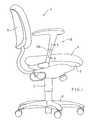
- FIG 1diagrammatically illustrates a chair 2, often referred to as an office-type chair.
- This chairemploys a center pedestal 3 which projects upwardly from a wheeled base 4.
- a suitable seat assemblyis mounted on an upper end of the center pedestal 3.
- the seat assemblyincludes a chair seat 6 and a chair control or seat frame 5.
- the chair control 5supports the chair seat 6 and is mounted thereto.
- a chair back 7projects upwardly from a location above the rear edge of the chair seat 6.
- the chair 2is provided with a pair of height-adjustable arm assemblies 8 mounted thereon, namely right and left assemblies which are respectively disposed adjacent the right and left sides of the seat 6 so as to project upwardly therefrom to hence permit the chair occupant to be seated therebetween.
- the right and left chair arm assemblies 8are substantially identical except for being mirror images of one another, and only the right side assembly is visible in Figure 1.
- the right side height-adjustable arm assembly 8includes an arm upright 10 which is fixed to and projects upwardly from adjacent the seat 6.
- the arm upright 10 in the illustrated embodimentis generally L-shaped and includes a base leg 10B which is fixed to the seat frame 5, and also includes a vertically elongate and upwardly cantilevered leg or support segment 10A.
- the support segment 10Ahas an elongate plastic sleeve 12 fixed vertically therein.
- the sleeve 12is constructed of two parts which effectively snap together.
- the sleeve 12defines a guide bore 13 which extends through the sleeve.
- the sleeve 12further defines interiorly thereof a gear rack 14 which has a plurality of uniformly vertically spaced notches as shown in Figure 3.
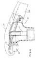
- the arm assembly 8further includes an armrest 28 having an upper portion or arm cap 28A for supporting an occupant's arm thereon and a lower cover portion 28B extending downwardly from the upper portion.
- the armrest 28also includes an arm element 21 having a slide tube 22 fixed thereto and projecting downwardly therefrom.
- the tube 22, in the illustrated embodiment,is of rectangular cross-section and is slidably supported within the guide bore 13 of the sleeve 12.
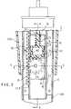
- the arm assembly 8additionally includes a compact cartridge assembly 15 which is secured interiorly of the tube 22.
- the cartridge assembly 15includes a generally channel-shaped housing 16 which is fixed within the tube 22.
- the tube 22has a window or aperture 38 defined in a vertical side wall 22A thereof as shown in Figure 3, which window 38 communicates with the interior of the housing 16 through an open side thereof.
- a gear 24is rotatably supported within the housing 16 by a pin 17 which extends transversely between and is supported on opposite side walls of the housing 16.
- the gear 24is supported in the housing 16 such that a plurality of teeth on one side of the gear 24 project through the open side of the housing and extend through the aperture 38 so as to engage the plurality of vertically spaced notches of the gear rack 14 as shown in Figure 3.
- the housing 16further has an opening 36 defined within a top wall thereof.
- An elongate actuator rod 25projects downwardly through the tube 22 and the housing opening 36 and has a lock member 26 secured to the lower end thereof.
- the lock member 26includes a plurality of downwardly projecting locking teeth 27 which engage the upper toothed portion of the gear 24.
- the locking teeth 27are configured to be generally rectangularly shaped as shown in Figures 3 and 7.
- the locking teeth 27protrude downwardly from a substantially planar bottom portion 34 of the lock member 26.
- Figure 7depicts a side elevational view of the lock member 26 which shows the planar bottom portion of the lock member defining a line L from which the locking teeth 27 protrude.
- the locking teeth 27are configured to be generally rectangularly shaped and have generally parallel side surfaces which protrude substantially perpendicularly from a substantially planar wall portion of the lock member 26, the locking teeth 27 and the gear 24 cooperate so as to provide for a more positive locking relationship therebetween which reduces the likelihood of accidental disengagement between the locking teeth 27 and the gear 24.
- the lock member 26is vertically slidably confined within the cartridge housing 16 by being slidably engaged and positioned between the bight or base wall of the channel-shaped housing 16 and the wall 22A of the tube 22 as shown in Figure 3.
- a spring 29coacts between the top wall of housing 16 and the locking member 26 for movably biasing the locking teeth 27 downwardly in perpendicular relation relative to the rotational axis of the gear 24 into a position of meshed engagement with gear 24 as illustrated in Figure 3.
- the lock member 26is thus confined for movement in a direction which is substantially perpendicular to the rotational axis of the gear 24.
- the engaged or meshed relation between the locking teeth 27 and the teeth of gear 24also occurs on or is substantially centered along a radial line which intersects the gear axis and which is substantially parallel with the movement direction of the lock member 26.
- the actuator rod 25has its upper end coupled to an actuator lever 31.
- a first end of the actuator lever 31is urged downwardly against the arm element 21 at a pivot point 30.
- a second end of the actuator lever 31extends through an opening 32 defined in the arm element 21.
- a finger-engaging pad or button 33Secured to the second end of the actuator lever 31 is a finger-engaging pad or button 33.
- the pad 33is located adjacent to but under a forward end of the armrest 28 for easy engagement by an occupant's fingers.
Landscapes
- Health & Medical Sciences (AREA)
- Dentistry (AREA)
- General Health & Medical Sciences (AREA)
- Seats For Vehicles (AREA)
- Chairs For Special Purposes, Such As Reclining Chairs (AREA)
- Chair Legs, Seat Parts, And Backrests (AREA)
Abstract

Description
The invention relates to chairs with adjustable armsand, more particularly, to an armrest which can beconveniently vertically adjusted with respect to thechair seat.
Chairs designed for use particularly in officeenvironments and the like are being increasingly providedwith adjustment features so as to improve the ergonomicsof the chair, particularly in those situations where thechair is used for long periods of time, such as when anoccupant is working at a computer terminal, to provideimproved comfort and healthful support of the occupant'sbody. One of the areas which has been addressed toimprove such comfort relates to the chair arms, and sameknown chairs have provided arms having positionadjustability, particularly with respect to the abilityto vary the armrest height relative to the seat. Theknown chairs which possess height-adjustable chair armstypically employ vertically telescopic supports and acooperating releasable latch arrangement for permittingheight adjustment. Most knownarrangements, however, havedisadvantages, either from a manufacturing or structuralviewpoint, or from an operational viewpoint. Forexample, many of the structures are undesirably complex,and/or do not provide for approximately continuous heightadjustment (in contrast to discrete height adjustment ata small number of widely spaced-apart discrete positions)and/or have a less secure locking arrangement that mayallow disengagement of the locking parts which may causethe accidental lowering of the armrest relative to thechair seat and/or the overall support arrangement and cooperating latch mechanism is such as to make release ofthe latch and adjustment of arm height difficult orinconvenient, particularly to an occupant seated in thechair.
Examples of known height-adjustable chair arms areshown in the following U.S.A. patents: 5 439 267,5 435 626, 5 393 125, 5 393 124, 5 388 892, 5 382 079,5 368 365, 5 346 284, 5 324 096, 5 318 347 and 5 265 938.
Accordingly, it is an object of this invention toprovide a chair having a height-adjustable arm assemblyassociated therewith, which arm assembly significantlyimproves upon and overcomes many of the disadvantages asbriefly summarized above.
More specifically, the improved height-adjustablechair arm assembly of this invention provides an improvedlocking mechanism which extends through the armrest andinto the arm upright so as to permit easy and efficientunlocking and height adjustment if desired, with theoccupant in a seated position being able to easilyrelease and maintain the locking mechanism in a releasingposition, and with the occupant having the feel ofapproximately continuous height adjustment of the armassembly, while at the same time permitting the occupantto easily raise or lower the arm while seated, and thenpermit the locking mechanism to re-engage.
Briefly, the present invention comprises a chairhaving height-adjustable arm assemblies respectivelymounted adjacent opposite sides of a seat. Each armassembly includes a horizontally elongate armrest whichis connected to an upper end of an arm upright. The armupright includes a vertically oriented support segmentwhich has a guide bore defined therein. The armrestincludes a vertically elongate slide tube and ahorizontally elongate arm element. The arm element isconnected to an upper end of the slide tube. A lower endof the slide tube is movably mounted within the guide bore. A lock arrangement functions to permit the slidetube to be positioned relative to the support segment atany one of a plurality of height positions. The lockarrangement includes a cartridge assembly that has a gearwhich is rotatably supported and carried by the slidetube. The gear has a plurality of gear teeth whichengage with a series of vertically spaced notches (i.e. agear rack) defined within the support segment. A lockreleasing mechanism functions to displace a lock memberbetween a locking position and a releasing position. Thelock releasing mechanism includes an actuator lever andan actuator rod. The actuator lever is supported on thearm element and the actuator rod extends into the supportelement and mounts the lock member thereon. The lockmember has a plurality of locking teeth which engage thegear when the lock member is positioned in the lockingposition.
Other objects and purposes of the invention will beapparent to persons familiar with structures of thisgeneral type upon reading the following specification andinspecting the accompanying drawings.
Certain terminology will be used in the followingdescription for convenience in reference only, and willnot be limiting. For example, the words "upwardly","downwardly", "rightwardly" and "leftwardly" will referto directions in the drawings to which reference is made.It will be understood that the words "upwardly" and"downwardly" will also refer to the directions of heightadjustment of the armrest relative to the chair seat,these being the actual physical directions experienced bythe chair occupant during height adjustment. The words"inwardly" and "outwardly" will respectively refer todirections toward and away from the center of the chair,the center of the arm assembly, or designated partsthereof. Said terminology will include the wordsspecifically mentioned, derivatives thereof, and words ofsimilar import.
Figure 1 diagrammatically illustrates achair 2,often referred to as an office-type chair. This chairemploys acenter pedestal 3 which projects upwardly fromawheeled base 4. A suitable seat assembly is mounted onan upper end of thecenter pedestal 3. The seat assemblyincludes achair seat 6 and a chair control orseat frame 5. Thechair control 5 supports thechair seat 6 and ismounted thereto. A chair back 7 projects upwardly from alocation above the rear edge of thechair seat 6.
Thechair 2 is provided with a pair of height-adjustablearm assemblies 8 mounted thereon, namely rightand left assemblies which are respectively disposedadjacent the right and left sides of theseat 6 so as toproject upwardly therefrom to hence permit the chairoccupant to be seated therebetween. The right and leftchair arm assemblies 8 are substantially identical exceptfor being mirror images of one another, and only theright side assembly is visible in Figure 1.
Referring now to Figures 2-7, the right side height-adjustablearm assembly 8 includes an arm upright 10which is fixed to and projects upwardly from adjacent theseat 6. The arm upright 10 in the illustrated embodimentis generally L-shaped and includes abase leg 10B whichis fixed to theseat frame 5, and also includes avertically elongate and upwardly cantilevered leg orsupport segment 10A. Thesupport segment 10A has anelongateplastic sleeve 12 fixed vertically therein. Thesleeve 12 is constructed of two parts which effectivelysnap together. Thesleeve 12 defines aguide bore 13which extends through the sleeve. Thesleeve 12 furtherdefines interiorly thereof agear rack 14 which has aplurality of uniformly vertically spaced notches as shownin Figure 3.
Thearm assembly 8 further includes anarmrest 28having an upper portion orarm cap 28A for supporting anoccupant's arm thereon and alower cover portion 28Bextending downwardly from the upper portion. Thearmrest 28 also includes anarm element 21 having aslide tube 22fixed thereto and projecting downwardly therefrom. Thetube 22, in the illustrated embodiment, is of rectangularcross-section and is slidably supported within the guidebore 13 of thesleeve 12.
Thearm assembly 8 additionally includes acompactcartridge assembly 15 which is secured interiorly of thetube 22. Thecartridge assembly 15 includes a generally channel-shaped housing 16 which is fixed within thetube 22. Thetube 22 has a window oraperture 38 defined ina vertical side wall 22A thereof as shown in Figure 3,whichwindow 38 communicates with the interior of thehousing 16 through an open side thereof. Agear 24 isrotatably supported within thehousing 16 by apin 17which extends transversely between and is supported onopposite side walls of thehousing 16. Thegear 24 issupported in thehousing 16 such that a plurality ofteeth on one side of thegear 24 project through the openside of the housing and extend through theaperture 38 soas to engage the plurality of vertically spaced notchesof thegear rack 14 as shown in Figure 3.
Thehousing 16 further has anopening 36 definedwithin a top wall thereof. Anelongate actuator rod 25projects downwardly through thetube 22 and the housingopening 36 and has alock member 26 secured to the lowerend thereof. Thelock member 26 includes a plurality ofdownwardly projectinglocking teeth 27 which engage theupper toothed portion of thegear 24. Thelocking teeth 27 are configured to be generally rectangularly shaped asshown in Figures 3 and 7. Moreover, the lockingteeth 27protrude downwardly from a substantiallyplanar bottomportion 34 of thelock member 26. Figure 7 depicts aside elevational view of thelock member 26 which showsthe planar bottom portion of the lock member defining aline L from which the lockingteeth 27 protrude. Sincethe lockingteeth 27 are configured to be generallyrectangularly shaped and have generally parallel sidesurfaces which protrude substantially perpendicularlyfrom a substantially planar wall portion of thelockmember 26, the lockingteeth 27 and thegear 24 cooperateso as to provide for a more positive locking relationshiptherebetween which reduces the likelihood of accidentaldisengagement between the lockingteeth 27 and thegear 24.
Thelock member 26 is vertically slidably confinedwithin thecartridge housing 16 by being slidably engagedand positioned between the bight or base wall of thechannel-shapedhousing 16 and the wall 22A of thetube 22as shown in Figure 3. Aspring 29 coacts between the topwall ofhousing 16 and the lockingmember 26 for movablybiasing the lockingteeth 27 downwardly in perpendicularrelation relative to the rotational axis of thegear 24into a position of meshed engagement withgear 24 asillustrated in Figure 3. Thelock member 26 is thusconfined for movement in a direction which issubstantially perpendicular to the rotational axis of thegear 24. Also, the engaged or meshed relation betweenthe lockingteeth 27 and the teeth ofgear 24 also occurson or is substantially centered along a radial line whichintersects the gear axis and which is substantiallyparallel with the movement direction of thelock member 26.
To provide a close fit of thelock member 26 in thecartridge housing 16, vertically spaced pairs of fins orribs lockmember 26. To ensure the correct orientation of thelockmember 26, a horizontally spaced pair ofprojections 42are formed on thecartridge housing 16. Thefins 41 areformed vertically elongate so to be slidable between theprojections 42. Thefins 40, however, are T-shaped suchthat the horizontal legs thereof interfere with theprojections 42 to insure the proper orientation of thelock member 26 as seen in Figure 3.
Theactuator rod 25 has its upper end coupled to anactuator lever 31. A first end of theactuator lever 31is urged downwardly against thearm element 21 at apivotpoint 30. A second end of theactuator lever 31 extendsthrough anopening 32 defined in thearm element 21.Secured to the second end of theactuator lever 31 is afinger-engaging pad orbutton 33. Thepad 33 is located adjacent to but under a forward end of thearmrest 28 foreasy engagement by an occupant's fingers.
In operation, when the occupant presses thepad 33upwardly, theactuator rod 25 is pulled upwardly againstthe bias ofspring 29 so as to disengage the lockingteeth 27 from thegear 24, thus allowinggear 24 to rollalongrack 14 to permit height adjustment of thearmrest 28. When the occupant desires to lock thearmrest 28 ata certain height position, thepad 33 is released andspring 29 urges the lockingteeth 27 downwardly so as toautomatically reengage thegear 24 when the gear teethreach a position where they engage the slots definedbetween the lockingteeth 27.
Although a particular preferred embodiment of theinvention has been disclosed in detail for illustrativepurposes, it will be recognized that variation ormodifications of the disclosed apparatus, including therearrangement of parts, lie within the scope of thepresent invention.
Claims (20)
- In a chair having a seat assembly, a backprojecting upwardly from a location adjacent a rear edgeof the seat assembly, and a pair of height-adjustable armassemblies mounted on and disposed adjacent oppositesides of said seat assembly and projecting upwardly incantilevered relation therefrom, the improvement whereineach arm assembly comprises:an arm upright fixed to said seat assembly andincluding a vertically elongate support segment disposedon one side of said seat assembly, said support segmentdefining therein a vertically elongate guide bore whichis open at an upper end thereof;an armrest having a vertically elongate slide tubelengthwise movably supported within said guide bore andprojecting upwardly therefrom and terminating at an upperend part which is disposed at an elevation spacedupwardly above said seat assembly, said armrest furtherhaving a horizontally elongate arm element mounted on theupper end part of said slide tube and projectinghorizontally therefrom;a releasable lock arrangement coacting between saidsupport segment and said slide tube for permitting saidslide tube to be stationarily fixedly positioned relativeto said support segment at any one of a plurality ofselectable height positions, said lock arrangementincluding a gear which is rotatably supported and carriedin said slide tube, said gear having a plurality of gearteeth which engage with a series of vertically spacednotches which are defined within said support segment;anda lock releasing mechanism extending from saidarmrest into said support segment and including a lock member movable between a locking position and a releasingposition, said lock releasing mechanism further includingan actuator arm extending lengthwise of and movablysupported on said arm element and terminating in amanually-engagable button part disposed at an undersideof said arm element adjacent an end portion thereof, andan actuator rod extending interiorly and lengthwise ofsaid support segment and having an upper end cooperatingwith said actuator arm and a lower end coupled to thelock member, said lock member having a locking toothwhich engages said gear when the lock member ispositioned in the locking position.
- A chair according to claim 1, wherein said lockmember has a substantially planar bottom portion having aplurality of locking teeth extend downwardly therefrom.
- A chair according to claim 2, wherein saidlocking teeth are substantially rectangularly shaped.
- A chair according to Claim 1, wherein said lockarrangement includes a housing in which said gear isrotatably supported, said housing being fixedlypositioned within said slide tube.
- A chair according to Claim 4, wherein said lockarrangement includes a pin retained within said housing,said gear being supported by said pins for rotation aboutthe axis thereof.
- A chair according to Claim 4, wherein saidhousing has an opening defined within a top wall thereof,and said actuator rod extends through said opening ofsaid top wall.
- A chair according to Claim 6, wherein said lockarrangement includes a spring which is positioned aroundsaid actuator rod at a location between said lock memberand said top wall of said housing.
- A chair according to Claim 6, wherein saidhousing and said slide tube have openings defined invertical side walls thereof, and said gear is rotatablymounted within said housing such that gear teeth thereofextend through said apertures so as to engage the seriesof vertically spaced notches which are defined withinsaid support segment.
- A chair according to Claim 4, wherein said lockmember is fixed to a lower end of said actuator rod andis vertically slidably supported in said housing at aposition directly above said gear.
- A chair according to Claim 1, wherein saidactuator arm includes a first end which is biased againstsaid arm element at a pivot point, and a second end whichends through an opening defined within said arm element.
- A chair according to Claim 10, wherein saidupper end of said actuator rod is attached to saidactuator lever at a location between said first andsecond ends of said actuator arm.
- A height-adjustable arm assembly for a chair,comprising:an arm upright including a vertically elongatesupport segment, said support segment defining therein avertically elongate guide bore which is open at an upperend thereof;an armrest having an elongate slide tube lengthwisemovably supported within said guide bore and projecting upwardly therefrom and terminating at an upper end part,said armrest further having a horizontally elongate armelement mounted on the upper end part of said slide tubeand projecting horizontally therefrom;a releasable lock arrangement coacting between saidsupport segment and said slide tube for permitting saidslide tube to be stationarily fixedly positioned relativeto said support segment at any one of a plurality ofselectable height positions, said lock arrangementincluding a gear which is rotatably supported and carriedby said slide tube, said gear having a plurality of gearteeth which engage with a series of vertically spacednotches which are defined within said support segment,and a movable lock member positioned adjacent said gearwithin said slide tube, said lock member having aplurality of locking teeth which engage said gear whenthe lock member is positioned in the locking position;anda lock releasing mechanism extending from saidarmrest into said support segment for displacing the lockmember between a locking position and a releasingposition, said lock releasing mechanism including anactuator arm extending lengthwise of and movablysupported on said arm element and terminating in amanually-engagable button part disposed at an undersideof said arm element adjacent an end portion thereof, andan actuator rod extending interiorly and lengthwise ofsaid support segment and having an upper end cooperatingwith said actuator arm and a lower end coupled to thelock member.
- A chair according to claim 12, wherein saidlock member has a substantially planar bottom portion,and said plurality of locking teeth are substantiallyrectangularly shaped and extend downwardly from saidplanar bottom portion.
- A chair according to Claim 12, wherein saidlock arrangement includes a housing and a pin, and saidgear is rotatably supported by said pin within saidhousing for rotation about an axis which extendstransversely relative to the lengthwise extent of saidslide tube.
- A chair according to Claim 14, wherein saidhousing has an opening defined within a top wall thereof,and said actuator rod extends through said opening ofsaid top wall, and said lock member is verticallyslidably supported within said housing above said gear.
- A chair according to Claim 15, wherein saidlock arrangement further includes a spring which ispositioned around said actuator rod at a location betweensaid lock member and said top wall of said housing.
- A chair according to Claim 15, wherein saidslide tube and said housing have openings defined invertical side walls thereof, and said gear is rotatablymounted within said housing such that the gear teeththereof extend through said openings so as to engage theseries of vertically spaced notches which are definedwithin said support segment.
- A chair according to Claim 12, wherein saidactuator arm includes a first end which is biased againstsaid arm element at a pivot point, and a second end whichends through an opening defined within said arm element,and said upper end of said actuator rod is attached tosaid actuator lever at a location between said first endand said second end of said actuator lever.
- A height-adjustable arm assembly for a chair,comprising:an arm upright including an elongate supportsegment, said support segment defining therein anelongate guide bore which is open at an upper endthereof;an armrest having an elongate slide tube and an armelement, said slide tube having a first end which issupported within said guide bore and a second end whichis attached to said arm element;a releasable lock arrangement for permitting saidslide tube to be stationarily positioned relative to saidsupport segment at any one of a plurality of heightpositions, said lock arrangement including a gear whichis rotatably supported and carried by said slide tube,said gear having a plurality of gear teeth which engagewith a series of vertically spaced notches which aredefined within said support segment, and a movable lockmember positioned adjacent said gear; anda lock releasing mechanism for displacing said lockmember between a locking position and a releasingposition, said lock releasing mechanism including anactuator part supported adjacent said arm element andconnected to an actuator rod extending into said supportsegment, said lock member being coupled to a lower end ofsaid actuator rod and having one or more locking teethwhich engage said gear when the lock member is positionedin the locking position.
- A chair according to claim 19, wherein saidlock member has a substantially planar bottom portion,and each of said plurality of locking teeth aresubstantially rectangularly shaped and extend downwardlyfrom said planar bottom portion.
Applications Claiming Priority (2)
| Application Number | Priority Date | Filing Date | Title |
|---|---|---|---|
| US731712 | 1996-10-17 | ||
| US08/731,712US5829839A (en) | 1996-10-17 | 1996-10-17 | Height-adjustable chair arm assembly having gear-type adjusting mechanism |
Publications (2)
| Publication Number | Publication Date |
|---|---|
| EP0836819A2true EP0836819A2 (en) | 1998-04-22 |
| EP0836819A3 EP0836819A3 (en) | 2000-03-01 |
Family
ID=24940664
Family Applications (1)
| Application Number | Title | Priority Date | Filing Date |
|---|---|---|---|
| EP97308230AWithdrawnEP0836819A3 (en) | 1996-10-17 | 1997-10-16 | Height-adjustable chair arm assembly |
Country Status (3)
| Country | Link |
|---|---|
| US (1) | US5829839A (en) |
| EP (1) | EP0836819A3 (en) |
| CA (1) | CA2218222A1 (en) |
Cited By (13)
| Publication number | Priority date | Publication date | Assignee | Title |
|---|---|---|---|---|
| WO1998055006A2 (en) | 1997-06-06 | 1998-12-10 | Haworth, Inc. | Height adjustable chair arm |
| US6802566B2 (en) | 2000-09-28 | 2004-10-12 | Formway Furniture Limited | Arm assembly for a chair |
| US6840582B2 (en) | 2002-05-14 | 2005-01-11 | Formway Furniture Limited | Height adjustable arm assembly |
| USD509969S1 (en) | 2003-09-05 | 2005-09-27 | Steelcase Development Corporation | Seating unit |
| USD536890S1 (en) | 2004-03-03 | 2007-02-20 | Steelcase Development Corporation | Seating unit |
| GB2435296A (en)* | 2006-02-20 | 2007-08-22 | Hoolin Res Co Ltd | Elevation adjustment structure for a display device |
| USD703987S1 (en) | 2013-06-07 | 2014-05-06 | Steelcase Inc. | Chair |
| USD703988S1 (en) | 2013-06-07 | 2014-05-06 | Steelcase Inc. | Chair |
| USD704487S1 (en) | 2013-06-07 | 2014-05-13 | Steelcase Inc. | Chair |
| USD706547S1 (en) | 2013-06-07 | 2014-06-10 | Steelcase Inc. | Chair |
| USD707976S1 (en) | 2013-06-07 | 2014-07-01 | Steelcase Inc. | Chair |
| USD721529S1 (en) | 2013-06-07 | 2015-01-27 | Steelcase Inc. | Handle apparatus |
| USD1063474S1 (en) | 2022-09-07 | 2025-02-25 | Steelcase Inc. | Chair |
Families Citing this family (20)
| Publication number | Priority date | Publication date | Assignee | Title |
|---|---|---|---|---|
| US6053579A (en)* | 1996-12-27 | 2000-04-25 | Haworth, Inc. | Height-Adjustable chair arm assembly having cam-type adjusting mechanism |
| US6394553B1 (en) | 2000-06-09 | 2002-05-28 | Knoll, Inc. | Adjustable armrest assembly with single adjustment lever |
| US7125077B2 (en)* | 2002-10-25 | 2006-10-24 | L&P Property Management Company | Seat bolster adjustment apparatus and method |
| USD554384S1 (en) | 2004-06-07 | 2007-11-06 | Steelcase Development Corporation | Chair |
| USD552368S1 (en) | 2004-06-07 | 2007-10-09 | Steelcase Development Corporation | Chair |
| USD544722S1 (en) | 2004-06-07 | 2007-06-19 | Steelcase Development Corporation | Chair |
| US7011371B1 (en)* | 2004-11-29 | 2006-03-14 | Po-Chuan Tsai | Armrest assembly having a height adjustable function |
| US8235468B2 (en) | 2005-03-01 | 2012-08-07 | Haworth, Inc. | Arm assembly for a chair |
| WO2006094260A2 (en)* | 2005-03-01 | 2006-09-08 | Haworth, Inc. | Arm assembly for a chair |
| US7644991B2 (en) | 2006-06-02 | 2010-01-12 | Steelcase Inc. | Chair with folding armrest |
| USD572490S1 (en) | 2006-06-05 | 2008-07-08 | Steelcase Inc. | Chair |
| USD572914S1 (en) | 2006-06-05 | 2008-07-15 | Steelcase Inc. | Chair |
| US7434887B1 (en)* | 2008-01-03 | 2008-10-14 | Feng-Tien Hsien | Steplessly height-adjustable armrest structure |
| FR2958889A1 (en)* | 2010-04-20 | 2011-10-21 | Faurecia Sieges D Automobiles | DEVICE FOR ADJUSTING THE SEAT LENGTH FOR AN AUTOMOTIVE SEAT, AND SEAT COMPRISING SUCH A DEVICE |
| US9616785B2 (en) | 2014-01-09 | 2017-04-11 | PAC Seating Systems, Inc. | Infinitely vertically adjustable drop down armrest mechanism |
| US9974390B2 (en)* | 2016-08-18 | 2018-05-22 | Jenp-Jou Enterprise Co., Ltd. | Armrest |
| US10053173B1 (en)* | 2017-06-30 | 2018-08-21 | Back Forty Development, LLC | Height adjusting device |
| US9969448B1 (en)* | 2017-07-17 | 2018-05-15 | Kalloy Industrial Co., Ltd. | Bicycle seat adjustment device |
| CN209073846U (en)* | 2018-05-11 | 2019-07-09 | 杭州中泰实业集团有限公司 | A kind of Revolving chair tray that slider-crank mechanism is adjusted |
| FR3096619B1 (en)* | 2019-05-27 | 2024-08-02 | Faurecia Sieges Dautomobile | ARMREST SET FOR VEHICLE SEAT |
Family Cites Families (15)
| Publication number | Priority date | Publication date | Assignee | Title |
|---|---|---|---|---|
| US232790A (en)* | 1880-09-28 | Stool or chair | ||
| US208823A (en)* | 1878-10-08 | Improvement in piano-stools | ||
| US504683A (en)* | 1893-09-05 | Joseph r | ||
| GB191317332A (en)* | 1913-07-28 | 1914-04-02 | Dental Mfg Co Ltd | Improvements in and relating to Dental Chairs. |
| US2641309A (en)* | 1949-09-15 | 1953-06-09 | Bostrom Mfg Company | Torsion spring supported pedestal seat mounting |
| FR1067160A (en)* | 1951-12-11 | 1954-06-14 | Franz Minet Mobelfabrik A G | Table |
| FR1227895A (en)* | 1959-06-23 | 1960-08-24 | Height adjustment device for chairs and the like | |
| US3194187A (en)* | 1964-01-13 | 1965-07-13 | Borg Warner | Overbed table |
| FR2208502A5 (en)* | 1972-11-29 | 1974-06-21 | Regis Rene | |
| US4632458A (en)* | 1985-05-20 | 1986-12-30 | Fixtures Manufacturing Corporation | Chair back height adjustment mechanism |
| JPS639405A (en)* | 1986-06-28 | 1988-01-16 | アイシン精機株式会社 | Up-and-down movable headrest apparatus |
| US4951995A (en)* | 1989-10-10 | 1990-08-28 | Steelcase Inc. | Arm height adjustment mechanism for a chair |
| US5439267A (en)* | 1993-05-28 | 1995-08-08 | Steelcase Inc. | Chair with adjustable arm assemblies |
| US5382079A (en)* | 1993-10-25 | 1995-01-17 | Chromcraft Revington, Inc. | Adjustable arm attachable to a chair body |
| US5647638A (en)* | 1995-06-07 | 1997-07-15 | Haworth, Inc. | Height-adjustable chair arm assembly |
- 1996
- 1996-10-17USUS08/731,712patent/US5829839A/ennot_activeExpired - Lifetime
- 1997
- 1997-10-14CACA002218222Apatent/CA2218222A1/ennot_activeAbandoned
- 1997-10-16EPEP97308230Apatent/EP0836819A3/ennot_activeWithdrawn
Cited By (21)
| Publication number | Priority date | Publication date | Assignee | Title |
|---|---|---|---|---|
| WO1998055006A2 (en) | 1997-06-06 | 1998-12-10 | Haworth, Inc. | Height adjustable chair arm |
| US7441839B2 (en) | 2000-09-28 | 2008-10-28 | Formway Furniture Limited | Reclinable chair |
| US6802566B2 (en) | 2000-09-28 | 2004-10-12 | Formway Furniture Limited | Arm assembly for a chair |
| US7798573B2 (en) | 2000-09-28 | 2010-09-21 | Formway Furniture Limited | Reclinable chair |
| US6840582B2 (en) | 2002-05-14 | 2005-01-11 | Formway Furniture Limited | Height adjustable arm assembly |
| USD509969S1 (en) | 2003-09-05 | 2005-09-27 | Steelcase Development Corporation | Seating unit |
| USD534018S1 (en) | 2003-09-05 | 2006-12-26 | Steelcase Development Corporation | Control for seating unit |
| USD534364S1 (en) | 2003-09-05 | 2007-01-02 | Steelcase Development Corporation | Seating unit having armrests |
| USD543396S1 (en) | 2003-09-05 | 2007-05-29 | Steelcase Development Corporation | Back construction |
| USD543385S1 (en) | 2003-09-05 | 2007-05-29 | Steelcase Development Corporation | Seat and back arrangement |
| USD543397S1 (en) | 2003-09-05 | 2007-05-29 | Steelcase Development Corporation | Back construction |
| USD536890S1 (en) | 2004-03-03 | 2007-02-20 | Steelcase Development Corporation | Seating unit |
| GB2435296A (en)* | 2006-02-20 | 2007-08-22 | Hoolin Res Co Ltd | Elevation adjustment structure for a display device |
| GB2435296B (en)* | 2006-02-20 | 2008-04-02 | Hoolin Res Co Ltd | Adjusting structure |
| USD703987S1 (en) | 2013-06-07 | 2014-05-06 | Steelcase Inc. | Chair |
| USD703988S1 (en) | 2013-06-07 | 2014-05-06 | Steelcase Inc. | Chair |
| USD704487S1 (en) | 2013-06-07 | 2014-05-13 | Steelcase Inc. | Chair |
| USD706547S1 (en) | 2013-06-07 | 2014-06-10 | Steelcase Inc. | Chair |
| USD707976S1 (en) | 2013-06-07 | 2014-07-01 | Steelcase Inc. | Chair |
| USD721529S1 (en) | 2013-06-07 | 2015-01-27 | Steelcase Inc. | Handle apparatus |
| USD1063474S1 (en) | 2022-09-07 | 2025-02-25 | Steelcase Inc. | Chair |
Also Published As
| Publication number | Publication date |
|---|---|
| US5829839A (en) | 1998-11-03 |
| EP0836819A3 (en) | 2000-03-01 |
| CA2218222A1 (en) | 1998-04-17 |
Similar Documents
| Publication | Publication Date | Title |
|---|---|---|
| US5829839A (en) | Height-adjustable chair arm assembly having gear-type adjusting mechanism | |
| US6053579A (en) | Height-Adjustable chair arm assembly having cam-type adjusting mechanism | |
| US5007678A (en) | Chair back height adjustment mechanism | |
| US5795026A (en) | Height adjustable chair arm | |
| US4451084A (en) | Backrest height adjustment for office chair | |
| EP1699315B1 (en) | Chair with adjustable seat depth | |
| US4205878A (en) | Pull out headrest | |
| US4951995A (en) | Arm height adjustment mechanism for a chair | |
| US4191422A (en) | Adjustable headrest | |
| US6027169A (en) | Forward-rearward tilt control for chair | |
| US5393125A (en) | Height adjustable chair arm assembly | |
| CA2349882C (en) | Adjustable armrest assembly with single adjustment lever | |
| US5820207A (en) | Nursery chair | |
| AU6565101A (en) | Arm assembly for a chair | |
| WO1994028772A1 (en) | Adjustable width arm rest | |
| US5853222A (en) | Height-adjustable chair back | |
| US20020140266A1 (en) | Height-adjustment mechanism for a chair | |
| EP1568297A1 (en) | Chair with functional armrest | |
| CA2444513A1 (en) | Chair with adjustable arms and/or back | |
| EP0466489A1 (en) | Height-controllable chair | |
| CN214231804U (en) | Patient support device and user interface housing for a patient support device | |
| EP0027419A1 (en) | Articulating headrest for dental chair | |
| US6705678B1 (en) | Height-adjustable chair back | |
| JPH079161U (en) | Height adjustment mechanism for infant chair | |
| KR200292593Y1 (en) | a chair's armrest |
Legal Events
| Date | Code | Title | Description |
|---|---|---|---|
| PUAI | Public reference made under article 153(3) epc to a published international application that has entered the european phase | Free format text:ORIGINAL CODE: 0009012 | |
| AK | Designated contracting states | Kind code of ref document:A2 Designated state(s):DE GB IT | |
| AX | Request for extension of the european patent | Free format text:AL;LT;LV;RO;SI | |
| RIN1 | Information on inventor provided before grant (corrected) | Inventor name:DRAL, JOEL ROBERT Inventor name:WILKERSON, LARRY A. | |
| PUAL | Search report despatched | Free format text:ORIGINAL CODE: 0009013 | |
| AK | Designated contracting states | Kind code of ref document:A3 Designated state(s):AT BE CH DE DK ES FI FR GB GR IE IT LI LU MC NL PT SE | |
| AX | Request for extension of the european patent | Free format text:AL;LT;LV;RO;SI | |
| 17P | Request for examination filed | Effective date:20000901 | |
| AKX | Designation fees paid | Free format text:DE GB IT | |
| STAA | Information on the status of an ep patent application or granted ep patent | Free format text:STATUS: THE APPLICATION HAS BEEN WITHDRAWN | |
| 18W | Application withdrawn | Withdrawal date:20020124 |