EP0835952B1 - Meltblowing method and apparatus - Google Patents
Meltblowing method and apparatusDownload PDFInfo
- Publication number
- EP0835952B1 EP0835952B1EP97307932AEP97307932AEP0835952B1EP 0835952 B1EP0835952 B1EP 0835952B1EP 97307932 AEP97307932 AEP 97307932AEP 97307932 AEP97307932 AEP 97307932AEP 0835952 B1EP0835952 B1EP 0835952B1
- Authority
- EP
- European Patent Office
- Prior art keywords
- fluid
- orifices
- orifice
- body member
- fluid flows
- Prior art date
- Legal status (The legal status is an assumption and is not a legal conclusion. Google has not performed a legal analysis and makes no representation as to the accuracy of the status listed.)
- Expired - Lifetime
Links
Images


Classifications
- B—PERFORMING OPERATIONS; TRANSPORTING
- B05—SPRAYING OR ATOMISING IN GENERAL; APPLYING FLUENT MATERIALS TO SURFACES, IN GENERAL
- B05C—APPARATUS FOR APPLYING FLUENT MATERIALS TO SURFACES, IN GENERAL
- B05C5/00—Apparatus in which liquid or other fluent material is projected, poured or allowed to flow on to the surface of the work
- B05C5/02—Apparatus in which liquid or other fluent material is projected, poured or allowed to flow on to the surface of the work the liquid or other fluent material being discharged through an outlet orifice by pressure, e.g. from an outlet device in contact or almost in contact, with the work
- B05C5/027—Coating heads with several outlets, e.g. aligned transversally to the moving direction of a web to be coated
- B05C5/0275—Coating heads with several outlets, e.g. aligned transversally to the moving direction of a web to be coated flow controlled, e.g. by a valve
- B05C5/0279—Coating heads with several outlets, e.g. aligned transversally to the moving direction of a web to be coated flow controlled, e.g. by a valve independently, e.g. individually, flow controlled
- B—PERFORMING OPERATIONS; TRANSPORTING
- B29—WORKING OF PLASTICS; WORKING OF SUBSTANCES IN A PLASTIC STATE IN GENERAL
- B29C—SHAPING OR JOINING OF PLASTICS; SHAPING OF MATERIAL IN A PLASTIC STATE, NOT OTHERWISE PROVIDED FOR; AFTER-TREATMENT OF THE SHAPED PRODUCTS, e.g. REPAIRING
- B29C49/00—Blow-moulding, i.e. blowing a preform or parison to a desired shape within a mould; Apparatus therefor
- D—TEXTILES; PAPER
- D01—NATURAL OR MAN-MADE THREADS OR FIBRES; SPINNING
- D01D—MECHANICAL METHODS OR APPARATUS IN THE MANUFACTURE OF ARTIFICIAL FILAMENTS, THREADS, FIBRES, BRISTLES OR RIBBONS
- D01D4/00—Spinnerette packs; Cleaning thereof
- D01D4/02—Spinnerettes
- D01D4/025—Melt-blowing or solution-blowing dies
- D—TEXTILES; PAPER
- D01—NATURAL OR MAN-MADE THREADS OR FIBRES; SPINNING
- D01D—MECHANICAL METHODS OR APPARATUS IN THE MANUFACTURE OF ARTIFICIAL FILAMENTS, THREADS, FIBRES, BRISTLES OR RIBBONS
- D01D5/00—Formation of filaments, threads, or the like
- D01D5/08—Melt spinning methods
- D01D5/098—Melt spinning methods with simultaneous stretching
- D01D5/0985—Melt spinning methods with simultaneous stretching by means of a flowing gas (e.g. melt-blowing)
- D—TEXTILES; PAPER
- D04—BRAIDING; LACE-MAKING; KNITTING; TRIMMINGS; NON-WOVEN FABRICS
- D04H—MAKING TEXTILE FABRICS, e.g. FROM FIBRES OR FILAMENTARY MATERIAL; FABRICS MADE BY SUCH PROCESSES OR APPARATUS, e.g. FELTS, NON-WOVEN FABRICS; COTTON-WOOL; WADDING ; NON-WOVEN FABRICS FROM STAPLE FIBRES, FILAMENTS OR YARNS, BONDED WITH AT LEAST ONE WEB-LIKE MATERIAL DURING THEIR CONSOLIDATION
- D04H1/00—Non-woven fabrics formed wholly or mainly of staple fibres or like relatively short fibres
- D04H1/40—Non-woven fabrics formed wholly or mainly of staple fibres or like relatively short fibres from fleeces or layers composed of fibres without existing or potential cohesive properties
- D04H1/54—Non-woven fabrics formed wholly or mainly of staple fibres or like relatively short fibres from fleeces or layers composed of fibres without existing or potential cohesive properties by welding together the fibres, e.g. by partially melting or dissolving
- D04H1/56—Non-woven fabrics formed wholly or mainly of staple fibres or like relatively short fibres from fleeces or layers composed of fibres without existing or potential cohesive properties by welding together the fibres, e.g. by partially melting or dissolving in association with fibre formation, e.g. immediately following extrusion of staple fibres
- B—PERFORMING OPERATIONS; TRANSPORTING
- B05—SPRAYING OR ATOMISING IN GENERAL; APPLYING FLUENT MATERIALS TO SURFACES, IN GENERAL
- B05B—SPRAYING APPARATUS; ATOMISING APPARATUS; NOZZLES
- B05B7/00—Spraying apparatus for discharge of liquids or other fluent materials from two or more sources, e.g. of liquid and air, of powder and gas
- B05B7/02—Spray pistols; Apparatus for discharge
- B05B7/08—Spray pistols; Apparatus for discharge with separate outlet orifices, e.g. to form parallel jets, i.e. the axis of the jets being parallel, to form intersecting jets, i.e. the axis of the jets converging but not necessarily intersecting at a point
- B05B7/0884—Spray pistols; Apparatus for discharge with separate outlet orifices, e.g. to form parallel jets, i.e. the axis of the jets being parallel, to form intersecting jets, i.e. the axis of the jets converging but not necessarily intersecting at a point the outlet orifices for jets constituted by a liquid or a mixture containing a liquid being aligned
Definitions
- the inventionrelates generally to meltblowing processes and to die assemblies for practicing meltblowing processes, and more particularly to die assemblies with a plurality of adhesive dispensing orifices flanked on each . side by air dispensing orifices, wherein adhesive flows from the plurality of adhesive dispensing orifices are drawn stretched and elongated, subsequently referred to as "attenuated" by relatively high velocity, high temperature air flows from the air dispensing orifices to form adhesive , filaments, known for instance, from US-A-4785996.
- meltblowingis a process of forming fibers or filaments by drawing and attenuating a first fluid flow, like molten thermoplastic, with shear forces from an adjacent second fluid flow, like heated air, at high velocity relative to the first fluid flow.
- meltblown filamentsmay be continuous or discontinuous, and range in size between several tenths of a micron and several hundreds of microns depending on the meltblown material and requirements of a particular application.
- the applications for meltblowing processesinclude, among others, the formation of non-woven fabrics and the dispensing of meltblown adhesive materials for bonding substrates in the production of a variety of bodily fluid absorbing hygienic articles like disposable diapers and incontinence pads, sanitary napkins, patient underlays, and surgical dressings.
- US-A-4,826,415describes a melt blow die in which a number of capillary tubes are arranged in a common plane contacting each other along adjacent side walls to form an array.
- the array of tubesis clamped at one end between a pair of die blocks which form a chamber supplying melt of a thermoplastic resin into the capillary tubes.
- the other ends of the tubesare clamped between parallel lips of gas plates. Gas is blown through orifices formed between the outer surface of each tube and the gas plate lips to draw the melt.
- US-A-5,145,689describes an elongated die assembly including a triangular die tip defined by converging surfaces that form an apex with a plurality of orifices arranged in a series therealong. A continuous air passage formed by air plates disposed along and spaced apart from. the converging surfaces of the die tip directs converging. sheets of high temperature, high velocity air along the converging surfaces of the die tip toward the apex where the high velocity air draws and attenuates polymer flows dispensed from the plurality of orifices.
- US-A-5,145,689also discloses an actuatable valve assembly located upstream of the plurality of orifices to selectively control the polymer flow to the orifices in the die tip.
- the inventors of the present inventionrecognize that compressing and heating air required for forming meltblown adhesives and other filaments is an expensive aspect of the meltblowing process.
- the inventorsrecognize also that drawing and attenuating fluid dispensed from a series of orifices in a die with converging air flow sheets disposed along opposing sides of the series of orifices is an inefficient configuration for meltblowing processes that require substantial amounts of compressed air, which is costly. More specifically, a substantial portion of each air sheet contributes very little to the meltblowing process since only those portions of the air sheet proximate the opposing flanking sides of the individual fluid flows has any significant affect on the drawing and attenuation of the dispensed fluid.
- the shear component of the converging air flow sheetswhich is parallel to the dispensed fluid flow direction, contributes to the drawing and attenuation of the dispensed fluid.
- the compressive component of the converging air flow sheetswhich flows perpendicular to the dispensed fluid flow direction, does not contribute to the drawing and attenuation of the dispensed fluid.
- the inventorsrecognize further that maximizing the shear component of the air flow will maximize the rate at which the meltblown material is drawn and attenuated and reduce the required amounts of compressed air, which results in reduced production costs.
- the inventors of the present inventionrecognize that any residual fluid along a fluid supply conduit between an actuatable fluid supply control valve and a fluid dispensing orifice has a tendency to continue to flow from the fluid dispensing orifice after the fluid supply has been terminated.
- any continued fluid flow from the fluid orifice after the fluid supply is terminatedis highly undesirable.
- the inventorsrecognize also that it is necessary in many meltblown adhesive applications, including the manufacture of bodily fluid absorbing hygienic articles, to uniformly produce and apply the meltblown filaments.
- meltblown materialit is necessary to apply a consistent layer of meltblown material onto a substrate or other surface and to produce a well defined interface or boundary between areas covered and areas not covered by the meltblown material.
- accurate control over the application of meltblown adhesives onto specific areas of a substrateis absolutely necessary since only designated portions of the substrate require bonding whereas other areas either do not require bonding or are discarded as waste.
- meltblowing dieslimits the scope of meltblowing applications for which the dies may be used. More specifically, many meltblowing dies require precision machining techniques to fabricate the often very small diameter fluid dispensing orifices and other features of the die. For some applications the die fabrication requirements are at the limits of existing technologies, and in many other applications the die fabrication requirements are cost prohibitive.
- a meltblowing apparatusincludes a first fluid orifice in a body member; two second fluid orifices in the body member flanking the first fluid orifice on substantially opposing sides thereof, the first fluid orifice protruding relative to the two second fluid orifices, the first and second fluid orifices each having a corresponding fluid conduit disposed in the body member, and wherein a filament emanates from the first fluid orifice, characterised in that means are provided to cause the filament to vacillate substantially in a plane between the two second fluid orifices on substantially opposing sides of the first fluid orifice.
- a meltblowing methodincludes forming a filament by drawing a first fluid flow with two separate second fluid flows directed along substantially opposing sides of the first fluid flow; characterised in that the filament is vacillated substantially in a plane between the two second fluid flows along substantially opposing sides thereof.
- FIG. 1is a diagrammatic view of a meltblowing process or method wherein a first fluid is dispensed to form a fluid flow F1 at a first velocity and a second fluid is dispensed to form separate second fluid flows F2 at a second velocity along substantially opposing flanking sides of the first fluid flow F1.
- the first fluid flow F1is located between the separate second fluid flows F2, wherein the substantially opposing sides of the first fluid flow F1 are each flanked by the second fluid flows F2 to form an array of fluid flows as shown in FIG. 1.
- the second velocity of the second fluid flows F2is greater than the first velocity of the first fluid flow F1 so that the second fluid flows F2 draw and attenuate the first fluid flow F1 to form a first fluid filament FF.
- the length of the arrows F1 and F2is indicative of, though not proportional to, the relative velocities therebetween.
- the first fluid flow F1 and the second fluid flows F2are directed generally non-convergently.
- FIG. 1shows the first fluid flow F1 and flanking second fluid flows F2 directed in parallel, which maximizes the drawing effect of the shear component of the second fluid flows F2 on the first fluid flow F1.
- the methodmay be practiced, more generally, by dispensing the first fluid to form a plurality of first fluid flows F1 at the first velocity and dispensing the second fluid to form a plurality of second fluid flows F2 at the second velocity, wherein the plurality of first fluid flows F1 and the plurality of second fluid flows F2 are arranged in an alternating series so that each of the plurality of first fluid flows F1 is flanked on substantially opposing sides by one of the plurality of second fluid flows F2.
- each of the plurality of first fluid flows F1 in the alternating serieshas one of the plurality of second fluid flows F2 on substantially opposing sides of the first fluid flow F1.
- the second velocity of the plurality of second fluid flows F2is greater than the first velocity of the plurality of first fluid flows F1 so that the plurality of second fluid flows F2 draws and attenuates the plurality of first fluid flows F1 to form a plurality of first fluid filaments FF.
- the plurality of first fluid flows F1 and the plurality of second fluid flows F2 along the substantially opposing flanking sides of the first fluid flows F1are directed generally non-convergently as discussed above. According to this mode of practicing the invention, the arrangement of the plurality of first and second fluid flows in an alternating series utilizes relatively effectively the shear component of the plurality of second fluid flows F2 for drawing and attenuating the plurality of first fluid flows F1 to form the plurality of first fluid filaments.
- FIG. 1shows the first fluid flow F1 including the first fluid filament FF vacillating under the effect of the flanking second fluid flows F2, which vacillation is attributable generally to instability of the fluid flows.
- the first fluid flow vacillationis characterizeable generally by an amplitude parameter and a frequency parameter, which are variable.
- the vacillationmay be controlled, for example, by varying a spacing between the first fluid flow F1 and one or more of the flanking second fluid flows F2, or by varying an amount of one or more of the second fluid flows F2, or by varying a velocity of one or more of the second fluid flows F2.
- the frequency parameter of the vacillationis controlled generally by varying a velocity of the second fluid flows F2 relative to the velocity of the first fluid flow F1.
- the amplitude of the vacillationis controlled generally by varying a spacing between the first fluid flow F1 and the second fluid flows F2, or by varying the flow volummes or quantity of the second fluid flows F2.
- the symmetry of the vacillationis controlled generally by varying one of the second fluid flows F2 relative to the other of the second fluid flows F2. Control over vacillation symmetry is an effective means for controlling the edge profile or edge definition of the first fluid filament in some applications as further discussed below.
- FIG. 2ais a partial sectional view of an exemplary meltblowing die or body member 10 for practicing processes according to the present invention.
- the first fluidis dispensed from a first orifice 12 of the body member to form the first fluid flow F1
- the second fluidis dispensed from second orifices 14 to form separate second fluid flows F2 flanking substantially opposing sides of the first fluid flow F1 to form an orifice array 30, one of which is referenced in FIG. 2b.
- the body member 10may include a plurality of first orifices 12 each flanked on substantially opposing sides by one of a plurality of second orifices 14 to form the alternating series of first and second fluid flows discussed above.
- the body member 10may include a plurality of at least two arrays of orifices each formed by a first orifice and second orifices on substantially opposing sides of the first orifice.
- FIG. 2bshows a body member 10 having plurality of at least two orifice arrays 30 in a several exemplary configurations.
- a common surface 11 of the body member 10includes a first orifice array 32 and a second orifice array 34 arranged in parallel, though not necessarily collinear, to provide staggered first fluid filaments FF that vacillate in substantially parallel planes, only one of which is shown for clarity.
- the fluid filaments FF produced by the staggered orifice arrays 32 and 34may be controlled to overlap slightly.
- one orifice array 36is oriented at an angle relative to one of the other orifice arrays 32 or 34 to provide first fluid filaments FF that vacillate in intersecting planes as shown.
- one or more orifice arrays 30 and 38are located on other surfaces 13 and 19 of the body member 10 relative to other orifice arrays 32, 34, and 36 to provide a three dimensional fluid filament distribution.
- FIG. 2ashows one of the second orifices recessed in an aperture 15 of the body member 10 relative to the first orifice 12. According to this configuration, the recessed second orifice 14 prevents upward migration of first fluid flow from the first orifice 12 into the second orifice 14 to prevent obstruction thereof. In one embodiment, both of the plurality of second orifices 14 on each substantially opposing side of the first orifice 12 is recessed relative to the first orifice 12. FIG. 2a also shows the aperture 15 having an increasing taper extending away from the second orifice 14, which forms a tapered aperture 17. According to this alternative configuration, the tapered aperture 17 prevents upward migration of first fluid flow F1 from the first orifice 12 into the second orifice 14, as discussed above.
- the tapered aperture 17also modifies the second fluid flow F2, for example, by broadening or increasing the cross sectional area of the second fluid flow F2.
- both of the plurality of recesses 15 on substantially opposing sides of the first orifice 12has an increasing taper to form a tapered aperture 17 as discussed above.
- the first and second orifices 12 and 14 of the body member 10may have any cross sectional shape including circular, rectangular and generally polygonal shapes.
- a high pressure zone 16is generated proximate an output of the first orifice 12 with converging separate third fluid flows F3 to block residual first fluid flow from the first orifice 12 after a first fluid supply has been terminated.
- the converging third fluid flows F3are convergently directed from either the same side or from opposing sides of the series of first and second fluid flows F1 and F2 so that the converging third fluid flows F3 meet to form the high pressure zone 16 proximate the output of the first orifice 12.
- the high pressure zone 16may be formed by deflecting or otherwise converging the second fluid flows F2, wherein the deflected second fluid flows F2 form the converging third fluid flows F3.
- the converging third fluid flows F3 that form the high pressure zone 16 proximate the output of the first orifice 12do not have a component of third fluid flow F3 in the direction of the first fluid flow F1 to ensure that residual first fluid flow is blocked.
- This process of converging third fluid flows F3 to form high pressure zones 16 proximate the first orifice 12 for blocking residual first fluid flow after the first fluid supply has been terminatedis also applicable to blocking residual first fluid flow from each of a plurality of first orifices, wherein a corresponding high pressure zone 16 is generated proximate an output of each of the plurality of first orifices.
- separate first fluid flows F11 and F12are formed from the first orifice 12 by dispensing the first fluid through an increasing aperture 18 of the first orifice 12 and drawing the first fluid flow with the separate second fluid flows F2 at a second velocity greater than the first velocity of the first fluid flow, wherein the separate first fluid flows F11 and F12 form corresponding separate first fluid filaments.
- the flanking second fluid flows F2create corresponding low pressure zones on substantially opposing sides of the first fluid flow which tend to separate the first fluid flow emanating from the increasing aperture 18 of the first orifice 12. This process is also applicable to forming separate first fluid flows from one or more of a plurality of first orifices of a body member wherein a corresponding one or more of the first orifices 12 has an increasing aperture 18 as discussed above.
- Another mode of forming separate first fluid flows F11 and F12 from the first orifice 12includes generating a high pressure zone 16 proximate an output of the first orifice 12 with converging fourth fluid flows and drawing the first fluid flows F11 and F12 with the separate second fluid flows F2 at a second velocity greater than the first velocity of the first fluid flow, wherein the separate first fluid flows F11 and F12 form corresponding separate first fluid filaments.
- the fourth fluid flowsmay be convergently directed from opposing sides of the series formed by the first and second fluid flows, or the array, so that the converging fourth fluid flows meet to form the high pressure zone 16 as discussed above.
- the first orifice 12does not require an increasing aperture 18 for practicing this alternative aspect of the invention, which is also applicable to forming separate first fluid flows from each of a plurality of first orifices of a body member wherein a corresponding high pressure zone 16 is generated proximate an output of each of the plurality of first orifices.
- first fluidis dispensed from the plurality of first orifices to form the plurality of first fluid flows at substantially the same mass flow rate
- second fluidis dispensed from the plurality of second orifices to form the plurality of second fluid flows at substantially the same mass flow rate
- the mass flow rates of one or more of the plurality of first fluid flowsis controllable by varying either or both the size of the corresponding first orifice 12 and the fluid pressure across the corresponding first orifice 12, wherein the corresponding one or more first fluid flows have different mass flow rates.
- the mass flow rates of one or more of the plurality of second fluid flowsis similarly controllable.
- the meltblowing die or body member having a plurality of arrays or a plurality of first orifices and a plurality of second orifices arranged in an alternating seriesalso includes a first means for substantially uniformly distributing first fluid supplied to one or more of the plurality of first orifices 12 to form the plurality of first fluid flows F1 at the first velocity and at substantially the same mass flow rate, and a second means for substantially uniformly distributing second fluid supplied to one or more of the plurality of second orifices 14 to form the plurality of second fluid flows F2 at the second velocity and at substantially the same mass flow rate.
- the dispensing of the plurality first fluid filaments formed by drawing and attenuating the plurality of first fluid flows from the plurality of first orifices of the die assemblymay be controlled by controlling the distribution of first fluid to the plurality of first orifices 12.
- the exemplary die assembly 100comprises a plurality of laminated members or plates.
- the plates of FIGS. 3 a-3tare assembled one on top of the other beginning with the plate in FIG. 3a and ending with plate 3t.
- the plates of FIGS. 3f-3kcorrespond to the plates in FIGS. 4a-4f, respectively, and the plates of FIGS. 3f-3l corresponds to the assembly of FIG. 5, which shows an alternating series of the plurality of first and second orifices 110 and 120 as discussed above.
- the first and second fluids supplied to the die assembly 100are distributed to the plurality of first and second orifices 110 and 120 as follows.
- the first fluidis supplied from a first restrictor cavity inlet 132 in the plate of FIG. 3f, also shown in FIG. 4a, to a first restrictor cavity 130 in the plate of FIG. 3g, also shown in FIG. 4b, through a plurality of passages 134 in the plate of FIG. 3h, also shown in FIG. 4c, and into first accumulator cavity 140 in the plate of FIG. 3i, also shown in FIG. 4d, where the first fluid is accumulated.
- the first fluidis then supplied from the accumulator cavity 140 through a plurality of passages 136 in the plate of FIG. 3j, also shown in FIG. 4e, to a plurality of first slots 109 in the plate of FIG. 3k, also shown in FIG. 4f.
- the plurality of first slots 109form the plurality of first orifices 110 shown in FIG. 5 when the plate of FIG. 3k is disposed between the plate of FIG. 3j and the plate of FIG. 31.
- the second fluidis supplied from a second restrictor cavity inlet 152 in the plates of FIGS. 3f-3o to a second restrictor cavity 150 in the plate of FIG. 3o, through a plurality of passages 135 in the plate of FIG. 3n, and into a second accumulator cavity 160 in the plate of FIG. 3m where the second fluid is accumulated.
- the second fluid accumulated in the accumulator cavity 160is then supplied through a plurality of passages 137 in the plate of FIG. 31 to a plurality of second slots 119 in the plate of FIG. 3k.
- the first fluid mass flow rate through each of the passages 134is controlled by varying a size of the passages 134.
- the first fluid supplied from the first restrictor cavity 130is substantially uniformly distributed and supplied to the first accumulator cavity 140 by the plurality passages 134 having varying sizes to compensate for decreasing pressure along portions of the first restrictor cavity outlet and to provide substantially the same first fluid mass flow rate through each of the passages 134.
- the substantially uniformly distributed first fluidis accumulated in the first accumulator cavity 140 and supplied through a plurality of passages 136 at the first accumulator cavity outlet to the plurality of first orifices 110.
- the plurality of first orifices 110which are substantially the same size, dispense the uniformly distributed first fluid to form the plurality of first fluid flows at the first velocity and at substantially the same mass flow rate.
- the second fluid supplied from the second restrictor cavity 150is substantially uniformly distributed and supplied to the second accumulator cavity 160 by the plurality of passages 135 having varying sizes to compensate for decreasing pressure along portions of the second restrictor cavity outlet and to provide substantially the same second fluid mass flow rate through each of the passages 135.
- the substantially uniformly distributed second fluidis accumulated in the second accumulator cavity 160 and supplied through a plurality of passages 137 at the second accumulator cavity outlet to the plurality of second orifices 120.
- the plurality of second orifices 120which are substantially the same size, dispense the uniformly distributed second fluid to form the plurality of second fluid flows at the second velocity and at substantially the same mass flow rate.
- the fluid mass flow rates through any one or more of the orifices 110 and 120may be selectively varied by varying a size of the corresponding orifices.
- the fluid mass flow rate through any one or more of the first and second orifices 110 and 120may be selectively varied by varying a pressure across the corresponding orifices.
- the pressure across an orificemay be decreased, for example, by forming an additional cavity, which causes a fluid pressure drop, along the fluid flow path to the selected orifice. If the die assembly is fabricated from a plurality of individual plates as discussed above, the additional cavity or cavities may be formed readily in one of the existing plates or in an additional plate.
- FIG. 5shows the plurality of second slots 119, which form the plurality of second orifices 120, disposed in a recess with a tapered aperture 121 relative to the plurality of first slots 109, which form the plurality of first orifices 110.
- this configurationreduces the tendency of the first fluid flows to migrate from the plurality of first orifices 110 back upward and into the plurality of second orifices 120 and also modifies the plurality of second fluid flows.
- the plates of FIGS. 3j-31have corresponding tapered slots 121 to provide the tapered aperture when the plates of FIGS. 3j-31 are assembled.
- the plates of FIGS. 3j-31may have slot configurations to provide any combination of the first and second orifice configurations discussed above with respect to FIG. 2a.
- the die assembly 100includes a third means for generating a high pressure zone proximate an output of each of the plurality of first orifices 110 with converging third fluid flows, wherein the high pressure zone blocks residual fluid flow from the corresponding first orifice after terminating a supply of first fluid to the first orifice as discussed above.
- the plurality of second fluid flowsare diverted to form the high pressure zones as discussed below.
- the die assembly 100comprises a plurality of laminated members or plates, wherein the plates of FIGS. 3b-3f correspond to plates 502-506 in the partial die assembly of FIG. 6, respectively.
- the third fluidis supplied from a third fluid inlet 172 extending through the plates of FIGS. 3b-3e into a first distribution cavity 170 in the plate of FIG. 3e, through a plurality of orifices 173 in the plate of FIG. 3d, into a cavity 174 in the plate of FIG. 3c, and into a cavity 176 in the plate of FIG. 3b.
- the fourth fluidis then supplied from the cavity 176 through a first plurality of orifices 178 in the plate of FIG. 3c, which orifices 178 form a first component of the converging third fluid flows.
- the third fluidalso is supplied from the third fluid inlet 172 which continues to extend through the plates of FIGS. 3e-3q into a second distribution cavity 180 in the plate of FIG. 3q, into a plurality of orifices 183 in the plate of FIG. 3r, into a cavity 184 in the plate of FIG. 3s, and into a cavity 186 in the plate of FIG. 3t.
- the fourth fluidis then supplied from the cavity 186 through a second plurality of orifices 188 in the plate of FIG.
- the converging third fluid flowsare dispensed from the respective orifices 178 and 188 at substantially the same mass flow rate.
- the third fluid mass flow rate through any one or more of the orifices 178 and 188may be selectively varied as discussed above.
- the first component of the converging third fluid flowsemanates from the first plurality of orifices 178 and the second component of converging third fluid flows emanates from the second plurality of orifices 188 converge to form a high pressure zone proximate an output of each of the plurality of first orifices 110.
- the converging third fluid flows in this exemplary embodimentdo not have a flow component in the flow direction of the first fluid flows, wherein the plurality of high pressure zones are useable to stem or block the flow of residual fluid from the plurality of first fluid orifices after terminating a first fluid supply to the first fluid inlet 132.
- the converging third fluid flowsare useable to form separate first fluid flows as discussed above.
- the exemplary embodiments of the die assembly 100may be formed of a plurality of plates of substantially the same thickness, or alternatively, may be formed of a plurality of plates having different plate thicknesses, wherein each plate thickness is determined by the size of the conduits or cavities defined thereby as shown in FIGS. 3-5.
- the platesmay be formed from metals, plastics, and ceramics among other materials, and the plates may be fabricated by stamping, punching, chemical etching, machining, and laser cutting among other processes, which are relatively cost effective alternatives to the prior art.
- a die assembly 100comprising a plurality of plates, as shown in the exemplary embodiments, provides considerable design flexibility in the configuration of the arrays or orifices, and the fluid flow and the distribution paths, which design and fabrication are not limited by the constraints imposed by prior art drilling processes.
- the plates of the present die assemblymay be readily fabricated to produce die assemblies having configurations based on one or more of the exemplary configurations of FIG. 2b.
- FIG. 7is an exemplary die adapter assembly 200 for mounting the die assembly 100 and for supplying fluids thereto.
- the die adapter assembly 200includes a die assembly mounting interface 210 having a first fluid outlet port 212, a second fluid outlet port 214, and a control or third fluid outlet port 216, which are each coupled by corresponding conduits to corresponding fluid inlets ports 213, 215, and 217 on a body portion 220 of the adapter 200.
- the die adapter assembly 200includes a second interface 230 with a first fluid outlet port 232, a second fluid outlet port 234, and a control or third fluid outlet port 236, which are also coupled by corresponding conduit extensions, not shown, to corresponding fluid inlets ports 213, 215, and 217 on the body portion 220 of the adapter 200.
- the second mounting interface 230is oriented at an angle relative to the first mounting interface 210, which in the exemplary embodiment is a 90 degree angle.
- the die assembly 100is coupled to the adapter 200 by mounting the die assembly 100 on the mounting interface 210 or 230.
- a sealing memberlike an o-ring, not shown, is disposed in a seat about each of the fluid outlets of the mounting interface 210 and 230 to provide a seal between the die assembly 100 and the adapter 200.
- the die assembly 100 and mounting interfaces 210 and 230may also include mating alignment tabs to facilitate alignment and mounting of the die assembly 100 on the adapter 200.
- the die assembly 100is mounted between the adapter interface 210 and a corresponding retaining plate 240, which retains the die assembly 100 mounted on the interface.
- a threaded boltis disposed through a central bore 232 of the retaining plate 230, and through a central bore of the die assembly 100, and into a threaded bore 222 of the body portion 220 of the adapter assembly 200, which permits ready installation and removal of the die assembly 100 relative to the adapter assembly 200.
- a similar retaining plateis mounted on the unused mounting interface to seal the fluid outlet ports thereon.
- a second die assembly 100is mounted on the second mounting interface so that the adapter 200 supplies fluids simultaneously to two die assemblies.
- FIG. 3ais a die assembly fluid switching interface plate for diverting a single fluid flow to form either the second fluid flow or the third fluid flow as discussed above.
- the fluid flow switching plateincludes a first fluid inlet 132, a switched fluid inlet 190, a primary fluid flow path 192 which couples the fluid inlet 190 with the third fluid inlet 172, and a secondary fluid flow path 194 which couples the fluid inlet 190 with the second fluid inlet 152.
- the primary fluid flow path 192is a path of least resistance resulting from an asymmetry between the primary path 192 and the secondary path 194 so that fluid supplied to the fluid inlet 190 has a tendency to follow the curved primary fluid flow path 192 toward the third fluid inlet 172.
- the fluid from the fluid inlet 190is diverted from the primary path 192 to the secondary path 194 by introducing an obstruction along the primary path 192, which causes the fluid to flow along the secondary path 194 toward the second fluid inlet 152.
- the obstructionis a control air flow introduced from a control fluid inlet 193, which urges the switched fluid toward the secondary fluid flow path 194.
- the plate of FIG. 3aalso includes a slot 195 with opposing end portions coupled by corresponding ports 196 and 197 in the plate of FIG. 3b to a recess 198 formed in the adjacent plates of FIGS. 3c and 3d for fluid pressure balancing.
- the first fluid outlet 212, the second fluid outlet 214, and the control fluid outlet 216 of the die assembly adapter 200are coupled, respectively, to the first fluid inlet 132, the switched fluid inlet 190, and the control fluid inlet 193 of the switching plate of FIG. 3a to supply fluid to the die assembly 100.
- the die assembly adapter 200is coupled to an MR-1300 nozzle module available from ITW Dynatec, Hendersonville, Tennessee, USA which includes a pneumatically actuatable valve for controlling the supply of first fluid to the first fluid inlet 213 of the die assembly adapter 200.
- the control air inlet 215 of the adapter 200is coupled to the MR-1300 valve actuation air supply to supply control air to the control fluid inlet 193 of the die assembly 100, which directs fluid from the switched fluid inlet 190 to the fluid inlet 152 of the die assembly when the MR-1300 valve is opened to supply first fluid to the first fluid inlet 132 of the die assembly 100.
- the first fluid and the second fluid supplied to the die assembly 100are dispensed from the first and second orifices 110 and 120 as discussed above. And when the MR-1300 valve is closed to terminate the first fluid supply, control air to the control fluid inlet 193 of the die assembly 100 is terminated, wherein fluid from the switched fluid inlet 190 is directed to the fluid inlet 172 to form the converging air flows, which block first fluid from the first orifices as discussed above.
- FIG. 3zis a die assembly fluid interface plate useable as an alternative to the die assembly fluid switching interface plate in FIG 3a, wherein the fluid inlet 190 of the die assembly 100 is coupled directly to the second fluid inlet 152, and the fluid inlet 193 of the die assembly 100 is coupled directly to the third fluid inlet 172.
- the control air inlet 215 of the adapter 200is coupled to the MR-1300 valve actuation air supply to supply a control air to the fluid inlet 193 of the die assembly 100 when the MR-1300 valve is closed to terminate first fluid to the first fluid inlet 132 of the die assembly 100.
- This dedicated configurationprovides more responsive residual first fluid flow blocking since there is no switching delay required to form the converging third fluid flows.
- the converging third fluid flows of the die assemblythus form high pressure zones in the presence of, but are unaffected by, the second fluid flows, which draw and attenuate the first fluid flows.
- the fluid supplied to the fluid inlet 193is unrelated to the MR-1300 valve actuation air supply tc provide still more control over the respective fluid flows.
- the meltblowing method and apparatus disclosed hereindispense meltblown adhesives onto substrates in manufacturing processes including the production of bodily fluid absorbing hygienic articles.
- a configuration for these applicationswhich is shown in FIG. 7, a plurality of at least two adjacent die assemblies 100 are disposed in corresponding die assembly adapters 200 arranged side by side to form a linear array of the plurality of corresponding adjacent first and second orifices 110 and 120 of each of the adjacent die assemblies 100.
- the first and second orifices of the die assemblyhave dimensions between approximately 0.001 and 0.030 inches (0.025 and 0.75 mm) on each side. These dimensions are not limiting however, and may be more or less for these and other applications.
- At least one of the endmost first orifices of the plurality of adjacent die assemblieshas a modified first fluid flow vacillation to control the edge profile or edge definition of meltblown adhesive dispensed from the array of die assemblies according to the aspects and embodiments of the invention discussed above.
- the plurality of first orifices of the plurality of adjacent die assembliesare oriented to produce a slightly diverging pluralities of first fluid flows, which provide a uniform meltblown adhesive application onto the substrates.
- at least one or more of the plurality of first fluid flowsare at different mass flow rates according to one or more configurations discussed above.
- the plates of the die assembly 100may be assembled by soldering, brazing, mechanical clamping, fusion under high temperture and pressure, and adhesive bonding among other means.
Landscapes
- Engineering & Computer Science (AREA)
- Textile Engineering (AREA)
- Mechanical Engineering (AREA)
- Manufacturing & Machinery (AREA)
- Spinning Methods And Devices For Manufacturing Artificial Fibers (AREA)
- Nonwoven Fabrics (AREA)
- Absorbent Articles And Supports Therefor (AREA)
Description
- The invention relates generally to meltblowingprocesses and to die assemblies for practicing meltblowingprocesses, and more particularly to die assemblies with aplurality of adhesive dispensing orifices flanked on each .side by air dispensing orifices, wherein adhesive flows fromthe plurality of adhesive dispensing orifices are drawnstretched and elongated, subsequently referred to as"attenuated" by relatively high velocity, high temperatureair flows from the air dispensing orifices to form adhesive ,filaments, known for instance, from US-A-4785996.
- Meltblowing is a process of forming fibers or filamentsby drawing and attenuating a first fluid flow, like moltenthermoplastic, with shear forces from an adjacent secondfluid flow, like heated air, at high velocity relative tothe first fluid flow. These meltblown filaments may becontinuous or discontinuous, and range in size betweenseveral tenths of a micron and several hundreds of micronsdepending on the meltblown material and requirements of aparticular application. The applications for meltblowingprocesses include, among others, the formation of non-wovenfabrics and the dispensing of meltblown adhesive materialsfor bonding substrates in the production of a variety ofbodily fluid absorbing hygienic articles like disposablediapers and incontinence pads, sanitary napkins, patientunderlays, and surgical dressings.
- US-A-4,826,415 describes a melt blow die in which anumber of capillary tubes are arranged in a common planecontacting each other along adjacent side walls to form anarray. The array of tubes is clamped at one end between apair of die blocks which form a chamber supplying melt of athermoplastic resin into the capillary tubes. The otherends of the tubes are clamped between parallel lips of gasplates. Gas is blown through orifices formed between theouter surface of each tube and the gas plate lips to drawthe melt.
- US-A-5,145,689 describes an elongated die assemblyincluding a triangular die tip defined by convergingsurfaces that form an apex with a plurality of orificesarranged in a series therealong. A continuous air passageformed by air plates disposed along and spaced apart from.the converging surfaces of the die tip directs converging.sheets of high temperature, high velocity air along theconverging surfaces of the die tip toward the apex where thehigh velocity air draws and attenuates polymer flowsdispensed from the plurality of orifices. US-A-5,145,689also discloses an actuatable valve assembly located upstreamof the plurality of orifices to selectively control the polymer flow to the orifices in the die tip.
- The inventors of the present invention recognize that compressing andheating air required for forming meltblown adhesives and other filaments is anexpensive aspect of the meltblowing process. The inventors recognize also thatdrawing and attenuating fluid dispensed from a series of orifices in a die withconverging air flow sheets disposed along opposing sides of the series of orifices is aninefficient configuration for meltblowing processes that require substantial amounts ofcompressed air, which is costly. More specifically, a substantial portion of each airsheet contributes very little to the meltblowing process since only those portions of theair sheet proximate the opposing flanking sides of the individual fluid flows has anysignificant affect on the drawing and attenuation of the dispensed fluid. Also, only theshear component of the converging air flow sheets, which is parallel to the dispensedfluid flow direction, contributes to the drawing and attenuation of the dispensed fluid.The compressive component of the converging air flow sheets, which flowsperpendicular to the dispensed fluid flow direction, does not contribute to the drawingand attenuation of the dispensed fluid. The inventors recognize further thatmaximizing the shear component of the air flow will maximize the rate at which themeltblown material is drawn and attenuated and reduce the required amounts ofcompressed air, which results in reduced production costs.
- The inventors of the present invention recognize that any residual fluidalong a fluid supply conduit between an actuatable fluid supply control valve and afluid dispensing orifice has a tendency to continue to flow from the fluid dispensingorifice after the fluid supply has been terminated. In applications that require accuratedispensing of a meltblown fluid including the application of meltblown adhesives ontosubstrates, however, any continued fluid flow from the fluid orifice after the fluidsupply is terminated is highly undesirable. The inventors recognize also that it isnecessary in many meltblown adhesive applications, including the manufacture ofbodily fluid absorbing hygienic articles, to uniformly produce and apply the meltblown filaments. More specifically, it is necessary to apply aconsistent layer of meltblown material onto a substrate orother surface and to produce a well defined interface orboundary between areas covered and areas not covered by themeltblown material. In the production of bodily fluidabsorbing hygienic articles, for example, accurate controlover the application of meltblown adhesives onto specificareas of a substrate is absolutely necessary since onlydesignated portions of the substrate require bondingwhereas other areas either do not require bonding or arediscarded as waste.
- The inventors of the present invention recognizefurther that prior art manufacture and fabrication ofmeltblowing dies limits the scope of meltblowingapplications for which the dies may be used. Morespecifically, many meltblowing dies require precisionmachining techniques to fabricate the often very smalldiameter fluid dispensing orifices and other features ofthe die. For some applications the die fabricationrequirements are at the limits of existing technologies,and in many other applications the die fabricationrequirements are cost prohibitive.
- In view of the discussion above among otherconsiderations, there exists a demonstrated need for anadvancement in the art of meltblown processes and apparatusfor practicing meltblowing processes.
- It is therefore an object of the invention to providenovel meltblowing methods and novel apparatus forpracticing meltblowing methods that overcome problems inthe prior art.
- According to a first aspect of this invention, ameltblowing apparatus includes a first fluid orifice in abody member;
two second fluid orifices in the body member flankingthe first fluid orifice on substantially opposing sidesthereof,
the first fluid orifice protruding relative to the twosecond fluid orifices,
the first and second fluid orifices each having acorresponding fluid conduit disposed in the body member,and
wherein a filament emanates from the first fluidorifice,
characterised in that means are provided to cause thefilament to vacillate substantially in a plane between thetwo second fluid orifices on substantially opposing sidesof the first fluid orifice. - According to a further aspect of this invention, ameltblowing method includes forming a filament by drawinga first fluid flow with two separate second fluid flowsdirected along substantially opposing sides of the firstfluid flow;
characterised in that the filament is vacillatedsubstantially in a planebetween the two second fluid flows along substantiallyopposing sides thereof. - Particular embodiments of a method and apparatus inaccordance with this invention will now be described withreference to the accompanying drawings; in which:-
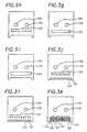
- FIG.1 is a diagrammatic view of an exemplarymeltblowing process according to one aspect of the presentinvention;
- FIG.2a is a partial sectional view of a meltblowingdie for practising meltblowing processes according toseveral other aspects of the present invention;
- FIG.2b is a perspective view of a meltblowing diehaving a plurality of arrays of fluid dispensing orificesarranged in configurations according to several exemplaryembodiments of the invention, wherein each array includesa first orifice flanked on both substantially opposingsides by a second orifice;
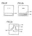
- FIGS.3a to 3t and 3z represent individual plates of adie assembly or body member according to an exemplaryembodiment of the invention;
- FIGS.4a-4f represent a partially exploded view of anexemplary die assembly or body member comprising severalindividual plates of FIGS.3;
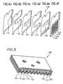
- FIG.5 is a perspective view of an exemplary partiallyassembled die assembly comprising several individual platesof FIG.3;
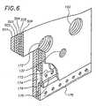
- FIG.6 is a partial perspective view of a portion of anexemplary die assembly comprising several individual platesof FIG.3; and,
- FIG.7 represents a partial perspective view of anexemplary die adapter assembly for coupling with theexemplary die assemblies of FIGS.3-5.
- FIG. 1 is a diagrammatic view of a meltblowing process or methodwherein a first fluid is dispensed to form a fluid flow F1 at a first velocity and a secondfluid is dispensed to form separate second fluid flows F2 at a second velocity alongsubstantially opposing flanking sides of the first fluid flow F1. According to thisconfiguration, the first fluid flow F1 is located between the separate second fluid flowsF2, wherein the substantially opposing sides of the first fluid flow F1 are each flankedby the second fluid flows F2 to form an array of fluid flows as shown in FIG. 1. Thesecond velocity of the second fluid flows F2 is greater than the first velocity of the firstfluid flow F1 so that the second fluid flows F2 draw and attenuate the first fluid flowF1 to form a first fluid filament FF. The length of the arrows F1 and F2 is indicativeof, though not proportional to, the relative velocities therebetween. The first fluidflow F1 and the second fluid flows F2 are directed generally non-convergently. FIG.1 shows the first fluid flow F1 and flanking second fluid flows F2 directed in parallel,which maximizes the drawing effect of the shear component of the second fluid flowsF2 on the first fluid flow F1. In other embodiments, however, it may be advantageousto divergently direct the first fluid flow F1 and the second fluid flows F2 to controlapplication or dispensing of the fluid filament FF without substantially adverselyaffecting the shear component of the second fluid flows F2 available for drawing thefirst fluid flow F1.
- The method may be practiced, more generally, by dispensing the firstfluid to form a plurality of first fluid flows F1 at the first velocity and dispensing thesecond fluid to form a plurality of second fluid flows F2 at the second velocity, whereinthe plurality of first fluid flows F1 and the plurality of second fluid flows F2 arearranged in an alternating series so that each of the plurality of first fluid flows F1 isflanked on substantially opposing sides by one of the plurality of second fluid flows F2.According to this configuration, each of the plurality of first fluid flows F1 in the alternating series has one of the plurality of second fluid flows F2 on substantiallyopposing sides of the first fluid flow F1. The second velocity of the plurality of secondfluid flows F2 is greater than the first velocity of the plurality of first fluid flows F1 sothat the plurality of second fluid flows F2 draws and attenuates the plurality of firstfluid flows F1 to form a plurality of first fluid filaments FF. The plurality of first fluidflows F1 and the plurality of second fluid flows F2 along the substantially opposingflanking sides of the first fluid flows F1 are directed generally non-convergently asdiscussed above. According to this mode of practicing the invention, the arrangementof the plurality of first and second fluid flows in an alternating series utilizes relativelyeffectively the shear component of the plurality of second fluid flows F2 for drawingand attenuating the plurality of first fluid flows F1 to form the plurality of first fluidfilaments.
- FIG. 1 shows the first fluid flow F1 including the first fluid filament FFvacillating under the effect of the flanking second fluid flows F2, which vacillation isattributable generally to instability of the fluid flows. The first fluid flow vacillationis characterizeable generally by an amplitude parameter and a frequency parameter,which are variable. The vacillation may be controlled, for example, by varying aspacing between the first fluid flow F1 and one or more of the flanking second fluidflows F2, or by varying an amount of one or more of the second fluid flows F2, or byvarying a velocity of one or more of the second fluid flows F2. The frequencyparameter of the vacillation is controlled generally by varying a velocity of the secondfluid flows F2 relative to the velocity of the first fluid flow F1. The amplitude of thevacillation is controlled generally by varying a spacing between the first fluid flow F1and the second fluid flows F2, or by varying the flow volummes or quantity of thesecond fluid flows F2. The symmetry of the vacillation is controlled generally byvarying one of the second fluid flows F2 relative to the other of the second fluid flowsF2. Control over vacillation symmetry is an effective means for controlling the edgeprofile or edge definition of the first fluid filament in some applications as further discussed below. These methods for controlling vacillation parameters of the first fluidflow F1 are also applicable to controlling vacillation parameters of a plurality of firstfluid flows and the corresponding plurality of first fluid filaments.
- FIG. 2a is a partial sectional view of an exemplary meltblowing die or
body member 10 for practicing processes according to the present invention.Generally, the first fluid is dispensed from afirst orifice 12 of the body member toform the first fluid flow F1, and the second fluid is dispensed fromsecond orifices 14to form separate second fluid flows F2 flanking substantially opposing sides of the firstfluid flow F1 to form anorifice array 30, one of which is referenced in FIG. 2b. Moregenerally, thebody member 10 may include a plurality offirst orifices 12 each flankedon substantially opposing sides by one of a plurality ofsecond orifices 14 to form thealternating series of first and second fluid flows discussed above. And still moregenerally, thebody member 10 may include a plurality of at least two arrays of orificeseach formed by a first orifice and second orifices on substantially opposing sides of thefirst orifice. FIG. 2b, for example, shows abody member 10 having plurality of at leasttwoorifice arrays 30 in a several exemplary configurations. According to oneconfiguration, acommon surface 11 of thebody member 10 includes afirst orificearray 32 and asecond orifice array 34 arranged in parallel, though not necessarilycollinear, to provide staggered first fluid filaments FF that vacillate in substantiallyparallel planes, only one of which is shown for clarity. In a more particularconfiguration, the fluid filaments FF produced by thestaggered orifice arrays orifice array 36 is oriented at an angle relative to one of theother orifice arrays more orifice arrays other surfaces body member 10 relative toother orifice arrays - FIG. 2a shows one of the second orifices recessed in an
aperture 15 of thebody member 10 relative to thefirst orifice 12. According to this configuration, the recessedsecondorifice 14 prevents upward migration of first fluid flow fromthefirst orifice 12 into thesecond orifice 14 to preventobstruction thereof. In one embodiment, both of the pluralityofsecond orifices 14 on each substantially opposing side ofthefirst orifice 12 is recessed relative to thefirst orifice 12. FIG. 2a also shows theaperture 15 having an increasingtaper extending away from thesecond orifice 14, which forms ataperedaperture 17. According to this alternativeconfiguration, the taperedaperture 17 prevents upwardmigration of first fluid flow F1 from thefirst orifice 12 intothesecond orifice 14, as discussed above. The taperedaperture 17 also modifies the second fluid flow F2, for example, bybroadening or increasing the cross sectional area of the secondfluid flow F2. In another embodiment, both of the plurality ofrecesses 15 on substantially opposing sides of thefirstorifice 12 has an increasing taper to form a taperedaperture 17 as discussed above. Generally, the first andsecond orifices body member 10 may have any cross sectionalshape including circular, rectangular and generally polygonalshapes. - In one mode of practicing the invention shown in FIG. 2a,a
high pressure zone 16 is generated proximate an output of thefirst orifice 12 with converging separate third fluid flows F3to block residual first fluid flow from thefirst orifice 12after a first fluid supply has been terminated. According tothis aspect of the invention, the converging third fluid flowsF3 are convergently directed from either the same side or fromopposing sides of the series of first and second fluid flows F1and F2 so that the converging third fluid flows F3 meet to formthehigh pressure zone 16 proximate the output of thefirstorifice 12. Alternatively, thehigh pressure zone 16 may beformed by deflecting or otherwise converging the second fluidflows F2, wherein the deflected second fluid flows F2 form theconverging third fluid flows F3. In the preferredconfiguration, the converging third fluid flows F3 that formthehigh pressure zone 16 proximate the output of thefirstorifice 12 do not have a component of third fluid flow F3 in the direction of the first fluid flow F1 to ensure that residualfirst fluid flow is blocked. This process of converging third fluid flows F3 to formhighpressure zones 16 proximate thefirst orifice 12 for blocking residual first fluid flowafter the first fluid supply has been terminated is also applicable to blocking residualfirst fluid flow from each of a plurality of first orifices, wherein a correspondinghighpressure zone 16 is generated proximate an output of each of the plurality of firstorifices. - In another mode of practicing the invention shown in FIG. 2a, separatefirst fluid flows F11 and F12 are formed from the
first orifice 12 by dispensing the firstfluid through an increasingaperture 18 of thefirst orifice 12 and drawing the first fluidflow with the separate second fluid flows F2 at a second velocity greater than the firstvelocity of the first fluid flow, wherein the separate first fluid flows F11 and F12 formcorresponding separate first fluid filaments. According to this aspect of the invention,the flanking second fluid flows F2 create corresponding low pressure zones onsubstantially opposing sides of the first fluid flow which tend to separate the first fluidflow emanating from the increasingaperture 18 of thefirst orifice 12. This process isalso applicable to forming separate first fluid flows from one or more of a plurality offirst orifices of a body member wherein a corresponding one or more of thefirstorifices 12 has an increasingaperture 18 as discussed above. - Another mode of forming separate first fluid flows F11 and F12 from the
first orifice 12 includes generating ahigh pressure zone 16 proximate an output of thefirst orifice 12 with converging fourth fluid flows and drawing the first fluid flows F11and F12 with the separate second fluid flows F2 at a second velocity greater than thefirst velocity of the first fluid flow, wherein the separate first fluid flows F11 and F12form corresponding separate first fluid filaments. According to this aspect of theinvention, the fourth fluid flows may be convergently directed from opposing sides ofthe series formed by the first and second fluid flows, or the array, so that theconverging fourth fluid flows meet to form thehigh pressure zone 16 as discussed above. Thefirst orifice 12 does not require an increasingaperture 18 for practicing this alternative aspect of theinvention, which is also applicable to forming separate firstfluid flows from each of a plurality of first orifices of abody member wherein a correspondinghigh pressure zone 16 isgenerated proximate an output of each of the plurality of firstorifices. - According to another aspect of the invention, first fluidis dispensed from the plurality of first orifices to form theplurality of first fluid flows at substantially the same massflow rate, and second fluid is dispensed from the plurality ofsecond orifices to form the plurality of second fluid flows atsubstantially the same mass flow rate. According to a relatedaspect of the invention, the mass flow rates of one or more ofthe plurality of first fluid flows is controllable by varyingeither or both the size of the corresponding
first orifice 12and the fluid pressure across the correspondingfirst orifice 12, wherein the corresponding one or more first fluid flowshave different mass flow rates. The mass flow rates of one ormore of the plurality of second fluid flows is similarlycontrollable. And according to a related aspect of theinvention, the meltblowing die or body member having aplurality of arrays or a plurality of first orifices and aplurality of second orifices arranged in an alternating series,as discussed above, also includes a first means forsubstantially uniformly distributing first fluid supplied toone or more of the plurality offirst orifices 12 to form theplurality of first fluid flows F1 at the first velocity and atsubstantially the same mass flow rate, and a second means forsubstantially uniformly distributing second fluid supplied toone or more of the plurality ofsecond orifices 14 to form theplurality of second fluid flows F2 at the second velocity andat substantially the same mass flow rate. According to thisaspect of the invention, the dispensing of the plurality firstfluid filaments formed by drawing and attenuating the pluralityof first fluid flows from the plurality of first orifices ofthe die assembly may be controlled by controlling thedistribution of first fluid to the plurality offirst orifices 12. - In FIGS. 3a-3t, 3z, 4a-4f and 5, the
exemplary dieassembly 100 comprises a plurality of laminated members or plates. The plates of FIGS.3 a-3t are assembled one on top of the other beginning with theplate in FIG. 3a and ending with plate 3t. The plates of FIGS.3f-3k correspond to the plates in FIGS. 4a-4f, respectively,and the plates of FIGS. 3f-3l corresponds to the assembly ofFIG. 5, which shows an alternating series of the plurality offirst andsecond orifices die assembly 100 aredistributed to the plurality of first andsecond orifices restrictor cavity inlet 132 in the plate of FIG. 3f, also shownin FIG. 4a, to a firstrestrictor cavity 130 in the plate ofFIG. 3g, also shown in FIG. 4b, through a plurality ofpassages 134 in the plate of FIG. 3h, also shown in FIG. 4c, and intofirst accumulator cavity 140 in the plate of FIG. 3i, alsoshown in FIG. 4d, where the first fluid is accumulated. Thefirst fluid is then supplied from theaccumulator cavity 140through a plurality ofpassages 136 in the plate of FIG. 3j,also shown in FIG. 4e, to a plurality offirst slots 109 in theplate of FIG. 3k, also shown in FIG. 4f. The plurality offirstslots 109 form the plurality offirst orifices 110 shown inFIG. 5 when the plate of FIG. 3k is disposed between the plateof FIG. 3j and the plate of FIG. 31. The second fluid issupplied from a secondrestrictor cavity inlet 152 in theplates of FIGS. 3f-3o to a secondrestrictor cavity 150 in theplate of FIG. 3o, through a plurality ofpassages 135 in theplate of FIG. 3n, and into asecond accumulator cavity 160 inthe plate of FIG. 3m where the second fluid is accumulated. Thesecond fluid accumulated in theaccumulator cavity 160 is thensupplied through a plurality ofpassages 137 in the plate ofFIG. 31 to a plurality ofsecond slots 119 in the plate of FIG.3k. - According to another aspect of the invention, the firstfluid mass flow rate through each of the
passages 134 iscontrolled by varying a size of thepassages 134. In theexemplary embodiment of FIGS. 3a-3t, the first fluid suppliedfrom the firstrestrictor cavity 130 is substantially uniformlydistributed and supplied to thefirst accumulator cavity 140 bytheplurality passages 134 having varying sizes to compensate for decreasing pressure along portions of the first restrictor cavity outlet and to providesubstantially the same first fluid mass flow rate through each of thepassages 134. Thesubstantially uniformly distributed first fluid is accumulated in thefirst accumulatorcavity 140 and supplied through a plurality ofpassages 136 at the first accumulatorcavity outlet to the plurality offirst orifices 110. And the plurality offirst orifices 110,which are substantially the same size, dispense the uniformly distributed first fluid toform the plurality of first fluid flows at the first velocity and at substantially the samemass flow rate. Similarly, the second fluid supplied from the secondrestrictor cavity 150 is substantially uniformly distributed and supplied to thesecond accumulator cavity 160 by the plurality ofpassages 135 having varying sizes to compensate for decreasingpressure along portions of the second restrictor cavity outlet and to providesubstantially the same second fluid mass flow rate through each of thepassages 135.The substantially uniformly distributed second fluid is accumulated in thesecondaccumulator cavity 160 and supplied through a plurality ofpassages 137 at the secondaccumulator cavity outlet to the plurality ofsecond orifices 120. And the plurality ofsecond orifices 120, which are substantially the same size, dispense the uniformlydistributed second fluid to form the plurality of second fluid flows at the secondvelocity and at substantially the same mass flow rate. - In alternative embodiments, however, the fluid mass flow rates throughany one or more of the
orifices second orifices - FIG. 5 shows the plurality of
second slots 119, which formthe plurality ofsecond orifices 120, disposed in a recess withatapered aperture 121 relative to the plurality offirst slots 109, which form the plurality offirst orifices 110. Asdiscussed above, this configuration reduces the tendency ofthe first fluid flows to migrate from the plurality offirstorifices 110 back upward and into the plurality ofsecondorifices 120 and also modifies the plurality of second fluidflows. To obtain this configuration, the plates of FIGS. 3j-31have corresponding taperedslots 121 to provide the taperedaperture when the plates of FIGS. 3j-31 are assembled. Inalternative embodiments, however, the plates of FIGS. 3j-31 mayhave slot configurations to provide any combination of thefirst and second orifice configurations discussed above withrespect to FIG. 2a. - According to another aspect of the invention, the
dieassembly 100 includes a third means for generating a highpressure zone proximate an output of each of the plurality offirst orifices 110 with converging third fluid flows, whereinthe high pressure zone blocks residual fluid flow from thecorresponding first orifice after terminating a supply of firstfluid to the first orifice as discussed above. And according toa related aspect of the invention, the plurality of secondfluid flows are diverted to form the high pressure zones asdiscussed below. - In the exemplary embodiments of FIGS. 3a-3t and 6, the
dieassembly 100 comprises a plurality of laminated members orplates, wherein the plates of FIGS. 3b-3f correspond to plates502-506 in the partial die assembly of FIG. 6, respectively.According to this exemplary configuration, the third fluid issupplied from a thirdfluid inlet 172 extending through theplates of FIGS. 3b-3e into afirst distribution cavity 170 inthe plate of FIG. 3e, through a plurality oforifices 173 inthe plate of FIG. 3d, into acavity 174 in the plate of FIG.3c, and into acavity 176 in the plate of FIG. 3b. The fourthfluid is then supplied from thecavity 176 through a firstplurality oforifices 178 in the plate of FIG. 3c, whichorifices 178 form a first component of the converging thirdfluid flows. The third fluid also is supplied from the thirdfluid inlet 172 which continues to extend through the plates of FIGS. 3e-3q into asecond distribution cavity 180 in the plate of FIG. 3q, into a plurality oforifices 183 in the plate of FIG. 3r, intoa cavity 184 in the plate of FIG. 3s, and into acavity 186 in the plate of FIG. 3t. Thefourth fluid is then supplied from thecavity 186 through a second plurality oforifices 188 in the plate of FIG. 3s, whichorifices 188 form a second component of theconverging third fluid flows. The plurality oforifices cavities cavities 174 and 184, respectively.According to this configuration, the converging third fluid flows are dispensed fromtherespective orifices orifices - According to the exemplary embodiment, the first component of theconverging third fluid flows emanates from the first plurality of
orifices 178 and thesecond component of converging third fluid flows emanates from the second pluralityoforifices 188 converge to form a high pressure zone proximate an output of each ofthe plurality offirst orifices 110. The converging third fluid flows in this exemplaryembodiment do not have a flow component in the flow direction of the first fluidflows, wherein the plurality of high pressure zones are useable to stem or block theflow of residual fluid from the plurality of first fluid orifices after terminating a firstfluid supply to the firstfluid inlet 132. In another application, the converging thirdfluid flows are useable to form separate first fluid flows as discussed above. - The exemplary embodiments of the
die assembly 100 may be formed ofa plurality of plates of substantially the same thickness, or alternatively, may be formedof a plurality of plates having different plate thicknesses, wherein each plate thicknessis determined by the size of the conduits or cavities defined thereby as shown in FIGS.3-5. The plates may be formed from metals, plastics, and ceramics among othermaterials, and the plates may be fabricated by stamping, punching, chemical etching, machining, and laser cutting among other processes, which are relatively cost effectivealternatives to the prior art. Further, adie assembly 100 comprising a plurality ofplates, as shown in the exemplary embodiments, provides considerable design flexibilityin the configuration of the arrays or orifices, and the fluid flow and the distributionpaths, which design and fabrication are not limited by the constraints imposed by priorart drilling processes. The plates of the present die assembly, for example, may bereadily fabricated to produce die assemblies having configurations based on one ormore of the exemplary configurations of FIG. 2b. - According to another aspect of the invention, the first and second fluidsare supplied to the corresponding first and second
fluid inlets die assembly 100. FIG. 7 is an exemplarydie adapterassembly 200 for mounting thedie assembly 100 and for supplying fluids thereto. Thedie adapter assembly 200 includes a dieassembly mounting interface 210 having a firstfluid outlet port 212, a secondfluid outlet port 214, and a control or thirdfluid outletport 216, which are each coupled by corresponding conduits to correspondingfluidinlets ports body portion 220 of theadapter 200. In anotherembodiment, thedie adapter assembly 200 includes asecond interface 230 with a firstfluid outlet port 232, a secondfluid outlet port 234, and a control or thirdfluid outletport 236, which are also coupled by corresponding conduit extensions, not shown, tocorrespondingfluid inlets ports body portion 220 of theadapter 200. Thesecond mounting interface 230 is oriented at an angle relative to thefirst mountinginterface 210, which in the exemplary embodiment is a 90 degree angle. - The
die assembly 100 is coupled to theadapter 200 by mounting thedieassembly 100 on the mountinginterface interface die assembly 100 and theadapter 200. Thedie assembly 100 and mountinginterfaces die assembly 100 on theadapter 200. In one configuration, thedie assembly 100 is mounted between theadapter interface 210 and acorresponding retaining plate 240, which retains thedieassembly 100 mounted on the interface. A threaded bolt, not shown, is disposedthrough acentral bore 232 of the retainingplate 230, and through a central bore ofthedie assembly 100, and into a threadedbore 222 of thebody portion 220 of theadapter assembly 200, which permits ready installation and removal of thedie assembly 100 relative to theadapter assembly 200. A similar retaining plate, not shown, ismounted on the unused mounting interface to seal the fluid outlet ports thereon. Inanother configuration, not shown, asecond die assembly 100 is mounted on the secondmounting interface so that theadapter 200 supplies fluids simultaneously to two dieassemblies. - FIG. 3a is a die assembly fluid switching interface plate for diverting asingle fluid flow to form either the second fluid flow or the third fluid flow asdiscussed above. The fluid flow switching plate includes a first
fluid inlet 132, aswitchedfluid inlet 190, a primaryfluid flow path 192 which couples thefluid inlet 190with the thirdfluid inlet 172, and a secondaryfluid flow path 194 which couples thefluid inlet 190 with the secondfluid inlet 152. The primaryfluid flow path 192 is apath of least resistance resulting from an asymmetry between theprimary path 192 andthesecondary path 194 so that fluid supplied to thefluid inlet 190 has a tendency tofollow the curved primaryfluid flow path 192 toward the thirdfluid inlet 172. Thefluid from thefluid inlet 190 is diverted from theprimary path 192 to thesecondarypath 194 by introducing an obstruction along theprimary path 192, which causes thefluid to flow along thesecondary path 194 toward the secondfluid inlet 152. In theexemplary embodiment, the obstruction is a control air flow introduced from acontrolfluid inlet 193, which urges the switched fluid toward the secondaryfluid flow path 194. The plate of FIG. 3a also includes aslot 195 with opposing end portions coupledby correspondingports recess 198 formed inthe adjacent plates of FIGS. 3c and 3d for fluid pressure balancing. According to this configuration, the firstfluid outlet 212, the secondfluid outlet 214, and thecontrolfluid outlet 216 of thedie assembly adapter 200 are coupled, respectively, to the firstfluid inlet 132, the switchedfluid inlet 190, and thecontrol fluid inlet 193 of theswitching plate of FIG. 3a to supply fluid to thedie assembly 100. - In one application, the
die assembly adapter 200 is coupled to an MR-1300nozzle module available from ITW Dynatec, Hendersonville, Tennessee, USA whichincludes a pneumatically actuatable valve for controlling the supply of first fluid to thefirstfluid inlet 213 of thedie assembly adapter 200. Thecontrol air inlet 215 of theadapter 200 is coupled to the MR-1300 valve actuation air supply to supply control airto thecontrol fluid inlet 193 of thedie assembly 100, which directs fluid from theswitchedfluid inlet 190 to thefluid inlet 152 of the die assembly when the MR-1300valve is opened to supply first fluid to the firstfluid inlet 132 of thedie assembly 100.According to this configuration, the first fluid and the second fluid supplied to thedieassembly 100 are dispensed from the first andsecond orifices control fluid inlet 193 of thedie assembly 100 is terminated, whereinfluid from the switchedfluid inlet 190 is directed to thefluid inlet 172 to form theconverging air flows, which block first fluid from the first orifices as discussed above. - FIG. 3z is a die assembly fluid interface plate useable as an alternativeto the die assembly fluid switching interface plate in FIG 3a, wherein the
fluid inlet 190 of thedie assembly 100 is coupled directly to the secondfluid inlet 152, and thefluid inlet 193 of thedie assembly 100 is coupled directly to the thirdfluid inlet 172.According to this configuration, thecontrol air inlet 215 of theadapter 200 is coupledto the MR-1300 valve actuation air supply to supply a control air to thefluid inlet 193of thedie assembly 100 when the MR-1300 valve is closed to terminate first fluid tothe firstfluid inlet 132 of thedie assembly 100. This dedicated configuration providesmore responsive residual first fluid flow blocking since there is no switching delayrequired to form the converging third fluid flows. The converging third fluid flows of the die assembly thus form high pressure zones in the presence of, but are unaffectedby, the second fluid flows, which draw and attenuate the first fluid flows. In yetanother configuration, the fluid supplied to thefluid inlet 193 is unrelated to the MR-1300valve actuation air supply tc provide still more control over the respective fluidflows. - According to another exemplary application, the meltblowing methodand apparatus disclosed herein dispense meltblown adhesives onto substrates inmanufacturing processes including the production of bodily fluid absorbing hygienicarticles. According to a configuration for these applications, which is shown in FIG.7, a plurality of at least two
adjacent die assemblies 100 are disposed in correspondingdie assembly adapters 200 arranged side by side to form a linear array of the pluralityof corresponding adjacent first andsecond orifices adjacentdie assemblies 100. For meltblown adhesive dispensing applications, the first andsecond orifices of the die assembly have dimensions between approximately 0.001 and0.030 inches (0.025 and 0.75 mm) on each side. These dimensions are not limitinghowever, and may be more or less for these and other applications. In oneconfiguration, at least one of the endmost first orifices of the plurality of adjacentdie assemblies has a modified first fluid flow vacillation to control the edge profileor edge definition of meltblown adhesive dispensed from the array of die assembliesaccording to the aspects and embodiments of the invention discussed above. Inanother configuration, the plurality of first orifices of the plurality of adjacent dieassemblies are oriented to produce a slightly diverging pluralities of first fluid flows,which provide a uniform meltblown adhesive application onto the substrates. Andin another configuration, at least one or more of the plurality of first fluid flows areat different mass flow rates according to one or more configurations discussed above.The plates of thedie assembly 100 may be assembled by soldering, brazing,mechanical clamping, fusion under high temperture and pressure, and adhesivebonding among other means.
Claims (18)
- A meltblowing apparatus including a first fluidorifice (12) in a body member (10);
two second fluid orifices (14) in the body member (10)flanking the first fluid orifice (12) on substantiallyopposing sides thereof,
the first fluid orifice (12) protruding relative tothe two second fluid orifices (14),
the first (12) and second (14) fluid orifices eachhaving a corresponding fluid conduit disposed in the bodymember (10), and
wherein a filament (FF) emanates from the first fluidorifice (12),
characterised in that means are provided to cause thefilament (FF) to vacillate substantially in a plane betweenthe two second fluid orifices (14) on substantiallyopposing sides of the first fluid orifice (12). - The apparatus of Claim 1, further comprising aplurality of first fluid orifices (12) in the body member(10) and a plurality of second fluid orifices (14) in thebody member (10), each first fluid orifice (12) flanked onsubstantially opposing sides by two separate second fluidorifices (14), the plurality of first fluid orifices (12)and the plurality of second fluid orifices (14) each havingcorresponding fluid conduits disposed in the body member(10).
- The apparatus of Claim 2, wherein a filament (FF)emanates from each one of the plurality of first fluidorifices (12), the plurality of filaments (FF) eachvacillating substantially in a plane between the two secondfluid orifices (14) on substantially opposing sides of thecorresponding first fluid orifice (12).
- The apparatus of Claims 3, wherein the plurality offirst fluid orifices (12) and the plurality of second fluidorifices (14) are aligned in a series.
- The apparatus of any one of Claims 1 to 3, wherein theconduits of the first (12) and second (14) fluid orificesare disposed non-convergently in the body member (10).
- The apparatus of any one of Claims 1 to 3, wherein theconduits of the first (12) and second (14) fluid orificesare disposed in parallel in the body member (10).
- The apparatus of Claims 1, 2, 5 or 6, wherein eachfirst fluid orifice (12) has associated therewith not morethan two second fluid orifices (14).
- The apparatus of any one of Claims 1 to 3, furthercomprising a moving substrate with each first fluid orifice(12) and the two second fluid orifices (14) disposed onopposing sides thereof and aligned non-parallel to adirection of the moving substrate.
- The apparatus of Claims 2, 3, 4 or 8, wherein theplurality of first fluid orifices (12) protrude relative tothe plurality of second fluid orifices (14).
- The apparatus of any one of Claims 1 to 9, whereinthe body member (10) comprises a plurality of at least twoplates (501-506).
- The apparatus of Claim 10, wherein the body member(10) comprises a plurality of parallel plates (501-506).
- A meltblowing method including forming a filament (FF)by drawing a first fluid flow (F1) with two separate secondfluid flows (F2) directed along substantially opposingsides of the first fluid flow (F1);
characterised in that the filament (FF) is vacillatedsubstantially in a planebetween the two second fluid flows (F2) along substantiallyopposing sides thereof. - The method of Claim 12, further comprising forming aplurality of filaments (FF) by drawing a correspondingplurality of first fluid flows (F1) each with correspondingtwo separate second fluid flows (F2) directed alongsubstantially opposing sides of the corresponding firstfluid flow (F1), and
vacillating each of the plurality of filaments (FF)substantially in a plane between the corresponding twosecond fluid flows (F2) along substantially opposing sidesthereof. - The method of Claim 12 or Claim 13, further comprisingforming each first fluid flow (F1) with a first fluiddispensed from a corresponding first orifice (12) in a bodymember (10), forming each second fluid flow (F2) with asecond fluid dispensed from a corresponding second orifice(14) in the body member (10), each first orifice (12)flanked on substantially opposing sides by two separatesecond fluid orifices (14), each first orifice (12)protruding relative to the corresponding two secondorifices (14).
- The method of Claim 12, 13 or 14, further comprisingdepositing each filament (FF) onto a substrate movingsubstantially non-parallel to the plane of vacillationthereof.
- The method of Claim 13 or Claim 14, further comprisingvacillating the plurality of filaments (FF) side by side inplanes which are substantially non-parallel to a directionof a moving substrate and depositing the filaments (FF)onto the moving substrate.
- The method of Claim 12, 13 or 14, further comprisingdirecting the first (F1) and second (F2) fluid flows non-convergently.
- The method of Claim 12, 13 or 14, further comprisingdirecting the first (F1) and second (F2) fluid flows inparallel.
Applications Claiming Priority (2)
| Application Number | Priority Date | Filing Date | Title |
|---|---|---|---|
| US717080 | 1996-10-08 | ||
| US08/717,080US5902540A (en) | 1996-10-08 | 1996-10-08 | Meltblowing method and apparatus |
Publications (2)
| Publication Number | Publication Date |
|---|---|
| EP0835952A1 EP0835952A1 (en) | 1998-04-15 |
| EP0835952B1true EP0835952B1 (en) | 2003-02-05 |
Family
ID=24880635
Family Applications (1)
| Application Number | Title | Priority Date | Filing Date |
|---|---|---|---|
| EP97307932AExpired - LifetimeEP0835952B1 (en) | 1996-10-08 | 1997-10-07 | Meltblowing method and apparatus |
Country Status (10)
| Country | Link |
|---|---|
| US (3) | US5902540A (en) |
| EP (1) | EP0835952B1 (en) |
| JP (2) | JP4008547B2 (en) |
| KR (1) | KR100239833B1 (en) |
| CN (1) | CN1088767C (en) |
| AU (1) | AU699826B2 (en) |
| BR (1) | BR9704982A (en) |
| CA (1) | CA2217684C (en) |
| DE (1) | DE69718870T2 (en) |
| TW (1) | TW353635B (en) |
Cited By (5)
| Publication number | Priority date | Publication date | Assignee | Title |
|---|---|---|---|---|
| USD588617S1 (en) | 2008-04-14 | 2009-03-17 | Nordson Corporation | Nozzle assembly |
| US7798434B2 (en) | 2006-12-13 | 2010-09-21 | Nordson Corporation | Multi-plate nozzle and method for dispensing random pattern of adhesive filaments |
| US8074902B2 (en) | 2008-04-14 | 2011-12-13 | Nordson Corporation | Nozzle and method for dispensing random pattern of adhesive filaments |
| US10213805B2 (en) | 2009-07-29 | 2019-02-26 | Illinois Tool Works Inc. | Wide pattern nozzle |
| US12226792B2 (en) | 2019-03-11 | 2025-02-18 | Illinois Tool Works Inc. | Nozzle arrangement for applying fluids, and method for producing a main body of such a nozzle arrangement |
Families Citing this family (158)
| Publication number | Priority date | Publication date | Assignee | Title |
|---|---|---|---|---|
| US5902540A (en) | 1996-10-08 | 1999-05-11 | Illinois Tool Works Inc. | Meltblowing method and apparatus |
| US6680021B1 (en) | 1996-07-16 | 2004-01-20 | Illinois Toolworks Inc. | Meltblowing method and system |
| US6422848B1 (en) | 1997-03-19 | 2002-07-23 | Nordson Corporation | Modular meltblowing die |
| US5882573A (en) | 1997-09-29 | 1999-03-16 | Illinois Tool Works Inc. | Adhesive dispensing nozzles for producing partial spray patterns and method therefor |
| US6077375A (en)* | 1998-04-15 | 2000-06-20 | Illinois Tool Works Inc. | Elastic strand coating process |
| JP2002512122A (en) | 1998-04-17 | 2002-04-23 | ノードソン コーポレーション | Method and apparatus for applying a controlled pattern of fibrous material to a moving support |
| US6235137B1 (en) | 1998-08-06 | 2001-05-22 | Kimberly-Clark Worldwide, Inc. | Process for manufacturing an elastic article |
| US6248097B1 (en) | 1998-08-06 | 2001-06-19 | Kimberly-Clark Worldwide, Inc. | Absorbent article with more conformable elastics |
| US6652693B2 (en) | 1998-08-06 | 2003-11-25 | Kimberly-Clark Worldwide, Inc. | Process for applying adhesive in an article having a strand material |
| US6051180A (en)* | 1998-08-13 | 2000-04-18 | Illinois Tool Works Inc. | Extruding nozzle for producing non-wovens and method therefor |
| US6200635B1 (en)* | 1998-08-31 | 2001-03-13 | Illinois Tool Works Inc. | Omega spray pattern and method therefor |
| US6602554B1 (en)* | 2000-01-14 | 2003-08-05 | Illinois Tool Works Inc. | Liquid atomization method and system |
| JP4474620B2 (en)* | 2000-03-14 | 2010-06-09 | ノードソン株式会社 | Apparatus and method for applying adhesive to thread-like or string-like object |
| US6719846B2 (en) | 2000-03-14 | 2004-04-13 | Nordson Corporation | Device and method for applying adhesive filaments to materials such as strands or flat substrates |
| US6361634B1 (en) | 2000-04-05 | 2002-03-26 | Kimberly-Clark Worldwide, Inc. | Multiple stage coating of elastic strands with adhesive |
| US6833179B2 (en) | 2000-05-15 | 2004-12-21 | Kimberly-Clark Worldwide, Inc. | Targeted elastic laminate having zones of different basis weights |
| US6969441B2 (en) | 2000-05-15 | 2005-11-29 | Kimberly-Clark Worldwide, Inc. | Method and apparatus for producing laminated articles |
| US6572033B1 (en) | 2000-05-15 | 2003-06-03 | Nordson Corporation | Module for dispensing controlled patterns of liquid material and a nozzle having an asymmetric liquid discharge orifice |
| US6435425B1 (en)* | 2000-05-15 | 2002-08-20 | Nordson Corporation | Module and nozzle for dispensing controlled patterns of liquid material |
| US8182457B2 (en) | 2000-05-15 | 2012-05-22 | Kimberly-Clark Worldwide, Inc. | Garment having an apparent elastic band |
| US6375099B1 (en)* | 2000-06-21 | 2002-04-23 | Illinois Tool Works Inc. | Split output adhesive nozzle assembly |
| US6520237B1 (en)* | 2000-07-24 | 2003-02-18 | Illinois Tool Works Inc | Variable spacing strand coating system and method |
| US6908421B2 (en)* | 2000-08-31 | 2005-06-21 | Japan Tobacco Inc. | Filter manufacturing machine |
| US20030131791A1 (en)* | 2000-11-21 | 2003-07-17 | Schultz Carl L. | Multiple orifice applicator system and method of using same |
| US6733831B2 (en) | 2001-10-30 | 2004-05-11 | Nordson Corporation | Method and apparatus for use in coating elongated bands |
| US6601741B2 (en) | 2001-11-28 | 2003-08-05 | Illinois Tool Works Inc. | Laminated distribution manifold plate system |
| US6939334B2 (en) | 2001-12-19 | 2005-09-06 | Kimberly-Clark Worldwide, Inc. | Three dimensional profiling of an elastic hot melt pressure sensitive adhesive to provide areas of differential tension |
| US6716309B2 (en) | 2001-12-21 | 2004-04-06 | Kimberly-Clark Worldwide, Inc. | Method for the application of viscous compositions to the surface of a paper web and products made therefrom |
| US6805965B2 (en) | 2001-12-21 | 2004-10-19 | Kimberly-Clark Worldwide, Inc. | Method for the application of hydrophobic chemicals to tissue webs |
| US6902796B2 (en) | 2001-12-28 | 2005-06-07 | Kimberly-Clark Worldwide, Inc. | Elastic strand bonded laminate |
| US20030173024A1 (en)* | 2002-03-15 | 2003-09-18 | Nordson Corporation | Method of securing elastic strands to flat substrates and products produced by the method |
| US20050013975A1 (en)* | 2003-07-14 | 2005-01-20 | Nordson Corporation | Method of securing elastic strands to flat substrates and products produced by the method |
| US6936125B2 (en)* | 2002-03-15 | 2005-08-30 | Nordson Corporation | Method of applying a continuous adhesive filament to an elastic strand with discrete bond points and articles manufactured by the method |
| WO2003086949A2 (en)* | 2002-04-12 | 2003-10-23 | Nordson Corporation | Applicator and nozzle for dispensing controlled patterns of liquid material |
| US6911232B2 (en)* | 2002-04-12 | 2005-06-28 | Nordson Corporation | Module, nozzle and method for dispensing controlled patterns of liquid material |
| US8012495B2 (en)* | 2002-05-07 | 2011-09-06 | Georgia-Pacific Consumer Products Lp | Lotion-treated tissue and towel |
| US7169400B2 (en)* | 2002-05-07 | 2007-01-30 | Fort James Corporation | Waterless lotion and lotion-treated substrate |
| US7335273B2 (en) | 2002-12-26 | 2008-02-26 | Kimberly-Clark Worldwide, Inc. | Method of making strand-reinforced elastomeric composites |
| US7015155B2 (en) | 2002-07-02 | 2006-03-21 | Kimberly-Clark Worldwide, Inc. | Elastomeric adhesive |
| US7316842B2 (en) | 2002-07-02 | 2008-01-08 | Kimberly-Clark Worldwide, Inc. | High-viscosity elastomeric adhesive composition |
| US6978486B2 (en) | 2002-07-02 | 2005-12-27 | Kimberly-Clark Worldwide, Inc. | Garment including an elastomeric composite laminate |
| US7316840B2 (en) | 2002-07-02 | 2008-01-08 | Kimberly-Clark Worldwide, Inc. | Strand-reinforced composite material |
| US6977026B2 (en)* | 2002-10-16 | 2005-12-20 | Kimberly-Clark Worldwide, Inc. | Method for applying softening compositions to a tissue product |
| EP1410900A1 (en)* | 2002-10-17 | 2004-04-21 | Reifenhäuser GmbH & Co. Maschinenfabrik | Method for producing a laminated web |
| US6761800B2 (en)* | 2002-10-28 | 2004-07-13 | Kimberly-Clark Worldwide, Inc. | Process for applying a liquid additive to both sides of a tissue web |
| US20040081794A1 (en)* | 2002-10-29 | 2004-04-29 | Titone David M. | Method for applying adhesive filaments to multiple strands of material and articles formed with the method |
| US7029756B2 (en) | 2002-11-06 | 2006-04-18 | Kimberly-Clark Worldwide, Inc. | Soft tissue hydrophilic tissue products containing polysiloxane and having unique absorbent properties |
| US6964725B2 (en)* | 2002-11-06 | 2005-11-15 | Kimberly-Clark Worldwide, Inc. | Soft tissue products containing selectively treated fibers |
| US6949168B2 (en)* | 2002-11-27 | 2005-09-27 | Kimberly-Clark Worldwide, Inc. | Soft paper product including beneficial agents |
| US7601218B2 (en)* | 2002-12-05 | 2009-10-13 | Valco Cincinnati, Inc. | Auto-tracking dispenser |
| ES2264289B1 (en)* | 2003-01-17 | 2007-12-01 | Universidad De Sevilla | NEW METHOD OF GENERATING FLUID MICRO-CURRENTS FOR THE PRODUCTION OF MICRO-BUBBLES, MICRO-FOAMS, MICRO-DROPS, MICRO-EMULSIONS, AND MICRO-CAPSULES. |
| US7578882B2 (en)* | 2003-01-22 | 2009-08-25 | Nordson Corporation | Module, nozzle and method for dispensing controlled patterns of liquid material |
| US7462240B2 (en)* | 2003-01-24 | 2008-12-09 | Nordson Corporation | Module, nozzle and method for dispensing controlled patterns of liquid material |
| US7018188B2 (en)* | 2003-04-08 | 2006-03-28 | The Procter & Gamble Company | Apparatus for forming fibers |
| US7396593B2 (en)* | 2003-05-19 | 2008-07-08 | Kimberly-Clark Worldwide, Inc. | Single ply tissue products surface treated with a softening agent |
| US6989061B2 (en)* | 2003-08-22 | 2006-01-24 | Kastalon, Inc. | Nozzle for use in rotational casting apparatus |
| US7270711B2 (en)* | 2004-06-07 | 2007-09-18 | Kastalon, Inc. | Nozzle for use in rotational casting apparatus |
| US7041171B2 (en)* | 2003-09-10 | 2006-05-09 | Kastalon, Inc. | Nozzle for use in rotational casting apparatus |
| US7168932B2 (en)* | 2003-12-22 | 2007-01-30 | Kimberly-Clark Worldwide, Inc. | Apparatus for nonwoven fibrous web |
| US6972104B2 (en)* | 2003-12-23 | 2005-12-06 | Kimberly-Clark Worldwide, Inc. | Meltblown die having a reduced size |
| US7470345B2 (en)* | 2003-12-30 | 2008-12-30 | Kimberly-Clark Worldwide, Inc. | Rolled paper product having high bulk and softness |
| US7601657B2 (en) | 2003-12-31 | 2009-10-13 | Kimberly-Clark Worldwide, Inc. | Single sided stretch bonded laminates, and methods of making same |
| US20050233667A1 (en)* | 2004-04-16 | 2005-10-20 | Tamko Roofing Products, Inc. | System and method for manufacturing polymer mat with reduced capacity spinning pumps |
| US7067009B2 (en)* | 2004-06-09 | 2006-06-27 | Illinois Tool Works Inc. | Strand guide implements or mechanisms for use in connection with material dispensing and coating nozzles |
| US7316552B2 (en)* | 2004-12-23 | 2008-01-08 | Kimberly-Clark Worldwide, Inc. | Low turbulence die assembly for meltblowing apparatus |
| US7465367B2 (en)* | 2005-01-07 | 2008-12-16 | Innovative Elastics Limited | Process for forming a laminate |
| US7906722B2 (en) | 2005-04-19 | 2011-03-15 | Palo Alto Research Center Incorporated | Concentrating solar collector with solid optical element |
| CN100518950C (en)* | 2005-06-14 | 2009-07-29 | 侯红蕾 | Controllable hot melt adhesive spinning method and device |
| US20070102841A1 (en)* | 2005-11-04 | 2007-05-10 | Nordson Corporation | Applicators and methods for dispensing a liquid material |
| US7765949B2 (en) | 2005-11-17 | 2010-08-03 | Palo Alto Research Center Incorporated | Extrusion/dispensing systems and methods |
| US20070169806A1 (en)* | 2006-01-20 | 2007-07-26 | Palo Alto Research Center Incorporated | Solar cell production using non-contact patterning and direct-write metallization |
| US20070107773A1 (en)* | 2005-11-17 | 2007-05-17 | Palo Alto Research Center Incorporated | Bifacial cell with extruded gridline metallization |
| US7799371B2 (en)* | 2005-11-17 | 2010-09-21 | Palo Alto Research Center Incorporated | Extruding/dispensing multiple materials to form high-aspect ratio extruded structures |
| WO2007064625A1 (en)* | 2005-12-01 | 2007-06-07 | 3M Innovative Properties Company | Multi-component liquid spray systems |
| US20070125888A1 (en)* | 2005-12-01 | 2007-06-07 | 3M Innovative Properties Company | Multi-component liquid spray systems |
| US20070125886A1 (en)* | 2005-12-01 | 2007-06-07 | 3M Innovative Properties Company | Methods of spraying multi-component liquids |
| US8388992B2 (en)* | 2006-03-28 | 2013-03-05 | Georgia-Pacific Consumer Products Lp | Anti-microbial hand towel with time-delay chromatic transfer indicator and absorbency rate delay |
| US7851693B2 (en) | 2006-05-05 | 2010-12-14 | Palo Alto Research Center Incorporated | Passively cooled solar concentrating photovoltaic device |
| US20080008865A1 (en) | 2006-06-23 | 2008-01-10 | Georgia-Pacific Consumer Products Lp | Antimicrobial hand towel for touchless automatic dispensers |
| US9770058B2 (en)* | 2006-07-17 | 2017-09-26 | 3M Innovative Properties Company | Flat-fold respirator with monocomponent filtration/stiffening monolayer |
| US7807591B2 (en)* | 2006-07-31 | 2010-10-05 | 3M Innovative Properties Company | Fibrous web comprising microfibers dispersed among bonded meltspun fibers |
| US7858163B2 (en)* | 2006-07-31 | 2010-12-28 | 3M Innovative Properties Company | Molded monocomponent monolayer respirator with bimodal monolayer monocomponent media |
| US7905973B2 (en)* | 2006-07-31 | 2011-03-15 | 3M Innovative Properties Company | Molded monocomponent monolayer respirator |
| US7902096B2 (en)* | 2006-07-31 | 2011-03-08 | 3M Innovative Properties Company | Monocomponent monolayer meltblown web and meltblowing apparatus |
| BRPI0714088B1 (en) | 2006-07-31 | 2017-04-04 | 3M Innovative Properties Co | method for the production of shaped filtration articles |
| US7754041B2 (en)* | 2006-07-31 | 2010-07-13 | 3M Innovative Properties Company | Pleated filter with bimodal monolayer monocomponent media |
| US7947142B2 (en)* | 2006-07-31 | 2011-05-24 | 3M Innovative Properties Company | Pleated filter with monolayer monocomponent meltspun media |
| US8029723B2 (en)* | 2006-07-31 | 2011-10-04 | 3M Innovative Properties Company | Method for making shaped filtration articles |
| US20100019058A1 (en)* | 2006-09-13 | 2010-01-28 | Vanderzwet Daniel P | Nozzle assembly for cold gas dynamic spray system |
| US7922471B2 (en) | 2006-11-01 | 2011-04-12 | Palo Alto Research Center Incorporated | Extruded structure with equilibrium shape |
| US7780812B2 (en)* | 2006-11-01 | 2010-08-24 | Palo Alto Research Center Incorporated | Extrusion head with planarized edge surface |
| US8322025B2 (en)* | 2006-11-01 | 2012-12-04 | Solarworld Innovations Gmbh | Apparatus for forming a plurality of high-aspect ratio gridline structures |
| US8226391B2 (en)* | 2006-11-01 | 2012-07-24 | Solarworld Innovations Gmbh | Micro-extrusion printhead nozzle with tapered cross-section |
| US7638438B2 (en)* | 2006-12-12 | 2009-12-29 | Palo Alto Research Center Incorporated | Solar cell fabrication using extrusion mask |
| US7928015B2 (en) | 2006-12-12 | 2011-04-19 | Palo Alto Research Center Incorporated | Solar cell fabrication using extruded dopant-bearing materials |
| USD550261S1 (en) | 2006-12-13 | 2007-09-04 | Nordson Corporation | Adhesive dispensing nozzle |
| US7951264B2 (en) | 2007-01-19 | 2011-05-31 | Georgia-Pacific Consumer Products Lp | Absorbent cellulosic products with regenerated cellulose formed in-situ |
| US20090025784A1 (en)* | 2007-02-02 | 2009-01-29 | Sol Focus, Inc. | Thermal spray for solar concentrator fabrication |
| WO2008093121A2 (en)* | 2007-02-02 | 2008-08-07 | G24 Innovations Limited | Photovoltaic electrochemical cell arrays |
| US7954449B2 (en) | 2007-05-08 | 2011-06-07 | Palo Alto Research Center Incorporated | Wiring-free, plumbing-free, cooled, vacuum chuck |
| US8033243B2 (en)* | 2007-06-29 | 2011-10-11 | Illinois Tool Works Inc. | Strand positioning guide having reversely oriented V-shaped slots for use in connection with strand coating applicators |
| US8093532B2 (en)* | 2008-03-31 | 2012-01-10 | Electro Scientific Industries, Inc. | Laser machining of fired ceramic and other hard and/or thick materials |
| KR101593022B1 (en)* | 2008-05-28 | 2016-02-11 | 니혼바이린 가부시기가이샤 | Spinning apparatus and apparatus and process for manufacturing nonwoven fabric |
| JP4994312B2 (en)* | 2008-06-12 | 2012-08-08 | 日本バイリーン株式会社 | Spinning apparatus and nonwoven fabric manufacturing apparatus |
| US7999175B2 (en)* | 2008-09-09 | 2011-08-16 | Palo Alto Research Center Incorporated | Interdigitated back contact silicon solar cells with laser ablated grooves |
| CA2735867C (en) | 2008-09-16 | 2017-12-05 | Dixie Consumer Products Llc | Food wrap basesheet with regenerated cellulose microfiber |
| US20100117254A1 (en)* | 2008-11-07 | 2010-05-13 | Palo Alto Research Center Incorporated | Micro-Extrusion System With Airjet Assisted Bead Deflection |
| US8704086B2 (en)* | 2008-11-07 | 2014-04-22 | Solarworld Innovations Gmbh | Solar cell with structured gridline endpoints vertices |
| US8117983B2 (en)* | 2008-11-07 | 2012-02-21 | Solarworld Innovations Gmbh | Directional extruded bead control |
| US20100118081A1 (en)* | 2008-11-07 | 2010-05-13 | Palo Alto Research Center Incorporated | Dead Volume Removal From An Extrusion Printhead |
| US20100221435A1 (en)* | 2008-11-07 | 2010-09-02 | Palo Alto Research Center Incorporated | Micro-Extrusion System With Airjet Assisted Bead Deflection |
| US8080729B2 (en)* | 2008-11-24 | 2011-12-20 | Palo Alto Research Center Incorporated | Melt planarization of solar cell bus bars |
| US20100130014A1 (en)* | 2008-11-26 | 2010-05-27 | Palo Alto Research Center Incorporated | Texturing multicrystalline silicon |
| US20100139754A1 (en)* | 2008-12-09 | 2010-06-10 | Palo Alto Research Center Incorporated | Solar Cell With Co-Planar Backside Metallization |
| US8960120B2 (en)* | 2008-12-09 | 2015-02-24 | Palo Alto Research Center Incorporated | Micro-extrusion printhead with nozzle valves |
| US20100139756A1 (en)* | 2008-12-10 | 2010-06-10 | Palo Alto Research Center Incorporated | Simultaneously Writing Bus Bars And Gridlines For Solar Cell |
| US20100206356A1 (en)* | 2009-02-18 | 2010-08-19 | Palo Alto Research Center Incorporated | Rotational Trough Reflector Array For Solar-Electricity Generation |
| US20100206302A1 (en)* | 2009-02-18 | 2010-08-19 | Palo Alto Research Center Incorporated | Rotational Trough Reflector Array For Solar-Electricity Generation |
| US20100224122A1 (en)* | 2009-03-09 | 2010-09-09 | Illinois Tool Works Inc. | Low pressure regulation for web moistening systems |
| US20100224703A1 (en)* | 2009-03-09 | 2010-09-09 | Illinois Tool Works Inc. | Pneumatic Atomization Nozzle for Web Moistening |
| US9186881B2 (en)* | 2009-03-09 | 2015-11-17 | Illinois Tool Works Inc. | Thermally isolated liquid supply for web moistening |
| US20100224123A1 (en) | 2009-03-09 | 2010-09-09 | Illinois Tool Works Inc. | Modular nozzle unit for web moistening |
| US8551562B2 (en) | 2009-07-17 | 2013-10-08 | Illnois Tool Works Inc. | Method for metering hot melt adhesives with variable adhesive volumes |
| CA2771144C (en) | 2009-08-14 | 2017-03-07 | The Procter & Gamble Company | Spinning die assembly and method for forming fibres using said assembly |
| US9573159B2 (en)* | 2009-08-31 | 2017-02-21 | Illinois Tool Works, Inc. | Metering system for simultaneously dispensing two different adhesives from a single metering device or applicator onto a common substrate |
| US9718081B2 (en)* | 2009-08-31 | 2017-08-01 | Illinois Tool Works Inc. | Metering system for simultaneously dispensing two different adhesives from a single metering device or applicator onto a common substrate |
| US9382643B2 (en) | 2009-09-01 | 2016-07-05 | 3M Innovative Properties Company | Apparatus, system, and method for forming nanofibers and nanofiber webs |
| WO2011119325A2 (en)* | 2010-03-25 | 2011-09-29 | 3M Innovative Properties Company | Composite layer |
| US8586129B2 (en) | 2010-09-01 | 2013-11-19 | Solarworld Innovations Gmbh | Solar cell with structured gridline endpoints and vertices |
| US9827711B2 (en) | 2011-04-21 | 2017-11-28 | Pregis Innovative Packaging Llc | Edge attached film-foam sheet |
| CN103764367B (en)* | 2011-09-02 | 2017-05-31 | 3M创新有限公司 | Strand, netting, die and method of manufacture |
| US8985485B2 (en) | 2011-10-03 | 2015-03-24 | Illinois Tool Works Inc. | Quasi melt blow down system |
| US9120190B2 (en) | 2011-11-30 | 2015-09-01 | Palo Alto Research Center Incorporated | Co-extruded microchannel heat pipes |
| US10371468B2 (en) | 2011-11-30 | 2019-08-06 | Palo Alto Research Center Incorporated | Co-extruded microchannel heat pipes |
| US8875653B2 (en)* | 2012-02-10 | 2014-11-04 | Palo Alto Research Center Incorporated | Micro-extrusion printhead with offset orifices for generating gridlines on non-square substrates |
| US9682392B2 (en) | 2012-04-11 | 2017-06-20 | Nordson Corporation | Method for applying varying amounts or types of adhesive on an elastic strand |
| CN102787374B (en)* | 2012-07-20 | 2015-02-25 | 东华大学 | Meltblown mold head for preparing ultrafine fibers |
| US9480996B2 (en) | 2012-09-18 | 2016-11-01 | Ilinois Tool Works Inc. | Fluid dispensing system with nozzle heater |
| CN103966674B (en)* | 2013-02-01 | 2017-04-12 | 郑州佳研磨具有限公司 | Spinneret plate for producing non-woven matrixes and cooling and shaping device of spinneret plate |
| US9827579B2 (en) | 2013-03-07 | 2017-11-28 | Sun Tool Corporation | Hot melt adhesive application method and hot melt adhesive application device |
| US9283579B2 (en) | 2013-03-12 | 2016-03-15 | Illinois Tool Works Inc. | Variable volume hot melt adhesive dispensing nozzle or die assembly with choke suppression |
| US10526729B2 (en) | 2014-02-24 | 2020-01-07 | Nanofiber, Inc. | Melt blowing die, apparatus and method |
| BR112016024875A2 (en) | 2014-04-25 | 2017-08-15 | Firestone Building Prod Co Llc | building materials including a non-woven layer of pressure sensitive adhesive |
| US9561654B2 (en) | 2014-11-26 | 2017-02-07 | Illinois Tool Works Inc. | Laminated nozzle with thick plate |
| US9849480B2 (en) | 2014-11-26 | 2017-12-26 | Illinois Tool Works Inc. | Laminated nozzle with thick plate |
| KR101670382B1 (en)* | 2015-03-10 | 2016-10-28 | 우범제 | Purge gas injection plate and manufacturing method thereof |
| JP6600981B2 (en)* | 2015-05-01 | 2019-11-06 | 日本ノズル株式会社 | Nonwoven fabric manufacturing equipment |
| US10130972B2 (en) | 2015-09-09 | 2018-11-20 | Illinois Tool Works Inc. | High speed intermittent barrier nozzle |
| CN107775946A (en)* | 2016-08-31 | 2018-03-09 | 岱纳包装(天津)有限公司 | A kind of human-computer interaction intelligent closed-loop control full-automatic blowing coating line and technique |
| CN107775942A (en)* | 2016-08-31 | 2018-03-09 | 岱纳包装(天津)有限公司 | A kind of method of extrusion glue embryo adjust automatically and control extrusion-blown modling based on 3D scannings |
| US11267595B2 (en) | 2016-11-01 | 2022-03-08 | Pregis Innovative Packaging Llc | Automated furniture bagger and material therefor |
| CN111556909B (en) | 2017-11-22 | 2024-04-09 | 挤压集团公司 | Meltblowing die tip assembly and method |
| MX2020008725A (en) | 2018-02-28 | 2020-09-21 | Illinois Tool Works | Nozzle for discharging one or more fluids. |
| CN108456940B (en)* | 2018-05-02 | 2020-10-23 | 嘉兴学院 | Fiber preparation device with asymmetric die head |
| DE102019106146A1 (en)* | 2019-03-11 | 2020-09-17 | Illinois Tool Works Inc. | NOZZLE ARRANGEMENT FOR APPLYING FLUIDS, SYSTEM WITH SUCH NOZZLE ARRANGEMENT AND METHOD FOR APPLYING FLUIDS |
| CN113891921A (en) | 2019-04-04 | 2022-01-04 | 艾利丹尼森公司 | Enhanced label components |
| JP7593741B2 (en) | 2020-03-26 | 2024-12-03 | ノードソン コーポレーション | Nozzle, adhesive application head, adhesive application device, and diaper manufacturing method |
| CN119877126B (en)* | 2025-03-31 | 2025-06-20 | 东华大学 | Melt-blown spinning die head, hollow crimped fiber base flocculus prepared from same and preparation method |
Citations (1)
| Publication number | Priority date | Publication date | Assignee | Title |
|---|---|---|---|---|
| US4785996A (en)* | 1987-04-23 | 1988-11-22 | Nordson Corporation | Adhesive spray gun and nozzle attachment |
Family Cites Families (131)
| Publication number | Priority date | Publication date | Assignee | Title |
|---|---|---|---|---|
| US33605A (en)* | 1861-10-29 | Improvement in modes of watering cattle on railroad-cars | ||
| US33159A (en)* | 1861-08-27 | Improved amalgamator | ||
| US33158A (en)* | 1861-08-27 | Improvement in harvesting-machines | ||
| US33448A (en)* | 1861-10-08 | Improvement in apparatus for tanning | ||
| US33481A (en)* | 1861-10-15 | Improvement in metallic cartridges | ||
| US2031387A (en)* | 1934-08-22 | 1936-02-18 | Schwarz Arthur | Nozzle |
| US2212448A (en)* | 1935-06-08 | 1940-08-20 | Owens Corning Fiberglass Corp | Method and apparatus for the production of fibers from molten glass and similar meltable materials |
| US2297726A (en)* | 1938-04-02 | 1942-10-06 | Thermo Plastics Corp | Method and apparatus for drying or the like |
| BE533186A (en) | 1948-11-05 | |||
| US2628386A (en)* | 1952-04-29 | 1953-02-17 | Modern Plastic Machinery Corp | Web extrusion die |
| US3038202A (en)* | 1959-01-28 | 1962-06-12 | Multiple Extrusions Inc | Method and apparatus for making multiple tube structures by extrusion |
| DE1132896B (en)* | 1961-01-05 | 1962-07-12 | Bayer Ag | Process for the production of granular or cylindrical granulates |
| US3178770A (en)* | 1962-01-19 | 1965-04-20 | Du Pont | Variable orifice extruder die |
| US3192563A (en)* | 1962-06-25 | 1965-07-06 | Monsanto Co | Laminated spinneret |
| US3176345A (en)* | 1962-06-25 | 1965-04-06 | Monsanto Co | Spinnerette |
| NL125332C (en)* | 1962-06-25 | |||
| US3204290A (en)* | 1962-12-27 | 1965-09-07 | Monsanto Co | Laminated spinneret |
| US3501805A (en)* | 1963-01-03 | 1970-03-24 | American Cyanamid Co | Apparatus for forming multicomponent fibers |
| US3253301A (en)* | 1963-01-14 | 1966-05-31 | Monsanto Co | Non-circular spinneret orifices |
| DE1584324A1 (en)* | 1965-04-15 | 1969-12-18 | Schneider & Co | Device for the production of ceramic bodies |
| US3334792A (en)* | 1966-05-19 | 1967-08-08 | Herculite Protective Fab | Adhesive applicator |
| DE1969216U (en)* | 1966-10-24 | 1967-09-28 | Du Pont | SPIN PACK. |
| NL6801610A (en)* | 1967-02-07 | 1968-08-08 | ||
| US3849241A (en)* | 1968-12-23 | 1974-11-19 | Exxon Research Engineering Co | Non-woven mats by melt blowing |
| US3978185A (en)* | 1968-12-23 | 1976-08-31 | Exxon Research And Engineering Company | Melt blowing process |
| US3613170A (en)* | 1969-05-27 | 1971-10-19 | American Cyanamid Co | Spinning apparatus for sheath-core bicomponent fibers |
| US3755527A (en)* | 1969-10-09 | 1973-08-28 | Exxon Research Engineering Co | Process for producing melt blown nonwoven synthetic polymer mat having high tear resistance |
| US3650866A (en)* | 1969-10-09 | 1972-03-21 | Exxon Research Engineering Co | Increasing strip tensile strength of melt blown nonwoven polypropylene mats of high tear resistance |
| US3704198A (en)* | 1969-10-09 | 1972-11-28 | Exxon Research Engineering Co | Nonwoven polypropylene mats of increased strip tensile strength |
| US3947537A (en)* | 1971-07-16 | 1976-03-30 | Exxon Research & Engineering Co. | Battery separator manufacturing process |
| BE787033A (en)* | 1971-08-06 | 1973-02-01 | Solvay | |
| BE795841A (en) | 1972-02-25 | 1973-08-23 | Montedison Spa | PROCESS FOR PREPARING FIBERS FROM POLYMERIC MATERIALS, SUITABLE FOR THE PREPARATION OF PAPER PULP |
| US3806289A (en) | 1972-04-05 | 1974-04-23 | Kimberly Clark Co | Apparatus for producing strong and highly opaque random fibrous webs |
| US3825379A (en)* | 1972-04-10 | 1974-07-23 | Exxon Research Engineering Co | Melt-blowing die using capillary tubes |
| US3861850A (en)* | 1972-09-05 | 1975-01-21 | Marvin E Wallis | Film forming head |
| US3920362A (en)* | 1972-10-27 | 1975-11-18 | Jeffers Albert L | Filament forming apparatus with sweep fluid channel surrounding spinning needle |
| FR2223318B1 (en)* | 1973-03-30 | 1978-03-03 | Saint Gobain | |
| US4015964A (en)* | 1973-03-30 | 1977-04-05 | Saint-Gobain Industries | Method and apparatus for making fibers from thermoplastic materials |
| US4052183A (en)* | 1973-04-24 | 1977-10-04 | Saint-Gobain Industries | Method and apparatus for suppression of pollution in toration of glass fibers |
| US4015963A (en)* | 1973-03-30 | 1977-04-05 | Saint-Gobain Industries | Method and apparatus for forming fibers by toration |
| US3888610A (en)* | 1973-08-24 | 1975-06-10 | Rothmans Of Pall Mall | Formation of polymeric fibres |
| US4100324A (en)* | 1974-03-26 | 1978-07-11 | Kimberly-Clark Corporation | Nonwoven fabric and method of producing same |
| US3942723A (en)* | 1974-04-24 | 1976-03-09 | Beloit Corporation | Twin chambered gas distribution system for melt blown microfiber production |
| US3970417A (en)* | 1974-04-24 | 1976-07-20 | Beloit Corporation | Twin triple chambered gas distribution system for melt blown microfiber production |
| US3923444A (en)* | 1974-05-03 | 1975-12-02 | Ford Motor Co | Extrusion die |
| US3954361A (en) | 1974-05-23 | 1976-05-04 | Beloit Corporation | Melt blowing apparatus with parallel air stream fiber attenuation |
| DD115206A5 (en)* | 1974-07-13 | 1975-09-12 | Monforts Fa A | Fluidic OSC |
| US4052002A (en)* | 1974-09-30 | 1977-10-04 | Bowles Fluidics Corporation | Controlled fluid dispersal techniques |
| US3981650A (en)* | 1975-01-16 | 1976-09-21 | Beloit Corporation | Melt blowing intermixed filaments of two different polymers |
| NL7507443A (en)* | 1975-06-23 | 1976-12-27 | Akzo Nv | MELTING EQUIPMENT. |
| US4185981A (en)* | 1975-08-20 | 1980-01-29 | Nippon Sheet Glass Co.,Ltd. | Method for producing fibers from heat-softening materials |
| DE2614596C3 (en)* | 1976-04-05 | 1980-03-13 | Vereinigte Glaswerke Gmbh, 5100 Aachen | Skimmer head for applying castable plastic layers on flat surfaces |
| US5035361A (en)* | 1977-10-25 | 1991-07-30 | Bowles Fluidics Corporation | Fluid dispersal device and method |
| US4151955A (en)* | 1977-10-25 | 1979-05-01 | Bowles Fluidics Corporation | Oscillating spray device |
| USRE33448E (en) | 1977-12-09 | 1990-11-20 | Fluidic oscillator and spray-forming output chamber | |
| USRE33605E (en) | 1977-12-09 | 1991-06-04 | Fluidic oscillator and spray-forming output chamber | |
| US4277436A (en)* | 1978-04-26 | 1981-07-07 | Owens-Corning Fiberglas Corporation | Method for forming filaments |
| US4231519A (en) | 1979-03-09 | 1980-11-04 | Peter Bauer | Fluidic oscillator with resonant inertance and dynamic compliance circuit |
| US4300876A (en)* | 1979-12-12 | 1981-11-17 | Owens-Corning Fiberglas Corporation | Apparatus for fluidically attenuating filaments |
| US4359445A (en)* | 1980-01-21 | 1982-11-16 | Owens-Corning Fiberglas Corporation | Method for producing a lofted mat |
| US4380570A (en)* | 1980-04-08 | 1983-04-19 | Schwarz Eckhard C A | Apparatus and process for melt-blowing a fiberforming thermoplastic polymer and product produced thereby |
| US4340563A (en)* | 1980-05-05 | 1982-07-20 | Kimberly-Clark Corporation | Method for forming nonwoven webs |
| US4457685A (en)* | 1982-01-04 | 1984-07-03 | Mobil Oil Corporation | Extrusion die for shaped extrudate |
| US4526733A (en)* | 1982-11-17 | 1985-07-02 | Kimberly-Clark Corporation | Meltblown die and method |
| DE3485710D1 (en)* | 1983-03-23 | 1992-06-11 | Barmag Barmer Maschf | SPINNING HEAD FOR MELTING SPINNING THREADS. |
| US4596364A (en)* | 1984-01-11 | 1986-06-24 | Peter Bauer | High-flow oscillator |
| US4818464A (en)* | 1984-08-30 | 1989-04-04 | Kimberly-Clark Corporation | Extrusion process using a central air jet |
| DE3506924A1 (en)* | 1985-02-27 | 1986-09-04 | Reifenhäuser GmbH & Co Maschinenfabrik, 5210 Troisdorf | DEVICE FOR SPINNING MONOFILE THREADS FROM THERMOPLASTIC PLASTIC |
| FR2579516B1 (en)* | 1985-04-01 | 1987-06-12 | Solvay | POWER SUPPLY FOR FLAT COEXTRUSION SECTOR |
| US4694992A (en)* | 1985-06-24 | 1987-09-22 | Bowles Fluidics Corporation | Novel inertance loop construction for air sweep fluidic oscillator |
| EP0252909B1 (en)* | 1986-01-10 | 1990-11-07 | Accurate Products Company | Melt blowing die and air manifold frame assembly |
| US4874451A (en)* | 1986-03-20 | 1989-10-17 | Nordson Corporation | Method of forming a disposable diaper with continuous/intermittent rows of adhesive |
| US4818463A (en)* | 1986-04-26 | 1989-04-04 | Buehning Peter G | Process for preparing non-woven webs |
| EP0265249B1 (en)* | 1986-10-21 | 1993-03-10 | Mitsui Petrochemical Industries, Ltd. | Melt blow die |
| US4747986A (en)* | 1986-12-24 | 1988-05-31 | Allied-Signal Inc. | Die and method for forming honeycomb structures |
| ES2042612T3 (en) | 1987-03-07 | 1993-12-16 | Fuller H B Licensing Financ | PROCEDURE FOR THE PERMANENT JOINING OF EXPANDABLE ELEMENTS IN THE FORM OF THREADS OR RIBBONS ON A SURFACE SUBSTRATE AS WELL AS USING IT FOR THE MANUFACTURE OF CURLED LEAF BAND SECTORS. |
| US4711683A (en) | 1987-03-09 | 1987-12-08 | Paper Converting Machine Company | Method and apparatus for making elastic diapers |
| US4746283A (en)* | 1987-04-01 | 1988-05-24 | Hobson Gerald R | Head tooling parison adapter plates |
| USRE33481E (en) | 1987-04-23 | 1990-12-11 | Nordson Corporation | Adhesive spray gun and nozzle attachment |
| US4905909A (en)* | 1987-09-02 | 1990-03-06 | Spectra Technologies, Inc. | Fluidic oscillating nozzle |
| US4955547A (en)* | 1987-09-02 | 1990-09-11 | Spectra Technologies, Inc. | Fluidic oscillating nozzle |
| US4983109A (en)* | 1988-01-14 | 1991-01-08 | Nordson Corporation | Spray head attachment for metering gear head |
| US4923706A (en)* | 1988-01-14 | 1990-05-08 | Thomas J. Lipton, Inc. | Process of and apparatus for shaping extrudable material |
| US4812276A (en)* | 1988-04-29 | 1989-03-14 | Allied-Signal Inc. | Stepwise formation of channel walls in honeycomb structures |
| US4949668A (en)* | 1988-06-16 | 1990-08-21 | Kimberly-Clark Corporation | Apparatus for sprayed adhesive diaper construction |
| US5067885A (en)* | 1988-06-17 | 1991-11-26 | Gencorp Inc. | Rapid change die assembly |
| US5069853A (en)* | 1988-06-17 | 1991-12-03 | Gencorp Inc. | Method of configuring extrudate flowing from an extruder die assembly |
| US4844003A (en) | 1988-06-30 | 1989-07-04 | Slautterback Corporation | Hot-melt applicator |
| US4960619A (en) | 1988-06-30 | 1990-10-02 | Slautterback Corporation | Method for depositing adhesive in a reciprocating motion |
| US5114752A (en)* | 1988-12-12 | 1992-05-19 | Nordson Corporation | Method for gas-aided dispensing of liquid materials |
| US5017116A (en)* | 1988-12-29 | 1991-05-21 | Monsanto Company | Spinning pack for wet spinning bicomponent filaments |
| US5312500A (en) | 1989-01-27 | 1994-05-17 | Nippon Petrochemicals Co., Ltd. | Non-woven fabric and method and apparatus for making the same |
| US5160746A (en)* | 1989-06-07 | 1992-11-03 | Kimberly-Clark Corporation | Apparatus for forming a nonwoven web |
| DE3927254A1 (en)* | 1989-08-18 | 1991-02-21 | Reifenhaeuser Masch | METHOD AND SPINNING NOZZLE UNIT FOR THE PRODUCTION OF PLASTIC THREADS AND / OR PLASTIC FIBERS INTO THE PRODUCTION OF A SPINNING FLEECE FROM THERMOPLASTIC PLASTIC |
| US5013232A (en)* | 1989-08-24 | 1991-05-07 | General Motors Corporation | Extrusion die construction |
| US5124111A (en)* | 1989-09-15 | 1992-06-23 | Kimberly-Clark Corporation | Method of forming a substantially continous swirled filament |
| US5066435A (en)* | 1989-09-16 | 1991-11-19 | Rohm Gmbh Chemische Fabrik | Process and system for producing multi-layer extrudate |
| US5169071A (en)* | 1990-09-06 | 1992-12-08 | Nordson Corporation | Nozzle cap for an adhesive dispenser |
| US5065943A (en)* | 1990-09-06 | 1991-11-19 | Nordson Corporation | Nozzle cap for an adhesive dispenser |
| US5075068A (en) | 1990-10-11 | 1991-12-24 | Exxon Chemical Patents Inc. | Method and apparatus for treating meltblown filaments |
| US5145689A (en)* | 1990-10-17 | 1992-09-08 | Exxon Chemical Patents Inc. | Meltblowing die |
| DE4040242A1 (en)* | 1990-12-15 | 1992-06-17 | Peter Roger Dipl Ing Nyssen | METHOD AND DEVICE FOR PRODUCING FINE FIBERS FROM THERMOPLASTIC POLYMERS |
| JP2602460B2 (en)* | 1991-01-17 | 1997-04-23 | 三菱化学株式会社 | Spinning nozzle, method for producing metal compound fiber precursor and method for producing inorganic oxide fiber using the spinning nozzle |
| US5094792A (en)* | 1991-02-27 | 1992-03-10 | General Motors Corporation | Adjustable extrusion coating die |
| US5129585A (en)* | 1991-05-21 | 1992-07-14 | Peter Bauer | Spray-forming output device for fluidic oscillators |
| US5207970A (en)* | 1991-09-30 | 1993-05-04 | Minnesota Mining And Manufacturing Company | Method of forming a web of melt blown layered fibers |
| DK0625939T3 (en) | 1992-02-13 | 1999-04-19 | Accurate Prod Co | Blow mold nozzle with preset air gap and offset |
| US5382312A (en) | 1992-04-08 | 1995-01-17 | Nordson Corporation | Dual format adhesive apparatus for intermittently disrupting parallel, straight lines of adhesive to form a band |
| US5165940A (en)* | 1992-04-23 | 1992-11-24 | E. I. Du Pont De Nemours And Company | Spinneret |
| DE69314343T2 (en) | 1992-07-08 | 1998-03-26 | Nordson Corp | DEVICE AND METHOD FOR APPLYING FOAM COATINGS |
| EP0579012B1 (en)* | 1992-07-08 | 1998-04-01 | Nordson Corporation | Apparatus and methods for applying discrete coatings |
| US5421921A (en)* | 1992-07-08 | 1995-06-06 | Nordson Corporation | Segmented slot die for air spray of fibers |
| US5354378A (en)* | 1992-07-08 | 1994-10-11 | Nordson Corporation | Slot nozzle apparatus for applying coatings to bottles |
| CA2098784A1 (en)* | 1992-07-08 | 1994-01-09 | Bentley Boger | Apparatus and methods for applying conformal coatings to electronic circuit boards |
| US5418009A (en)* | 1992-07-08 | 1995-05-23 | Nordson Corporation | Apparatus and methods for intermittently applying discrete adhesive coatings |
| US5275676A (en) | 1992-09-18 | 1994-01-04 | Kimberly-Clark Corporation | Method and apparatus for applying a curved elastic to a moving web |
| DE4332345C2 (en) | 1993-09-23 | 1995-09-14 | Reifenhaeuser Masch | Process and fleece blowing system for the production of a spunbonded web with high filament speed |
| US5478224A (en) | 1994-02-04 | 1995-12-26 | Illinois Tool Works Inc. | Apparatus for depositing a material on a substrate and an applicator head therefor |
| US5458291A (en) | 1994-03-16 | 1995-10-17 | Nordson Corporation | Fluid applicator with a noncontacting die set |
| ES2138238T3 (en) | 1994-10-12 | 2000-01-01 | Kimberly Clark Co | EXTRUSIONABLE THERMOPLASTIC POLYPROPYLENE COMPOSITION IN MELTING AND NON-WOVEN LAMINAR ELEMENT PREPARED FROM IT. |
| US5476616A (en) | 1994-12-12 | 1995-12-19 | Schwarz; Eckhard C. A. | Apparatus and process for uniformly melt-blowing a fiberforming thermoplastic polymer in a spinnerette assembly of multiple rows of spinning orifices |
| US5679379A (en) | 1995-01-09 | 1997-10-21 | Fabbricante; Anthony S. | Disposable extrusion apparatus with pressure balancing modular die units for the production of nonwoven webs |
| US5618347A (en) | 1995-04-14 | 1997-04-08 | Kimberly-Clark Corporation | Apparatus for spraying adhesive |
| US5618566A (en) | 1995-04-26 | 1997-04-08 | Exxon Chemical Patents, Inc. | Modular meltblowing die |
| US5620139A (en) | 1995-07-18 | 1997-04-15 | Nordson Corporation | Nozzle adapter with recirculation valve |
| US5902540A (en) | 1996-10-08 | 1999-05-11 | Illinois Tool Works Inc. | Meltblowing method and apparatus |
| US5904298A (en) | 1996-10-08 | 1999-05-18 | Illinois Tool Works Inc. | Meltblowing method and system |
| US5862986A (en) | 1996-07-16 | 1999-01-26 | Illinois Tool Works, Inc. | Hot melt adhesive applicator with metering gear-driven head |
| DE19715740A1 (en) | 1997-04-16 | 1998-10-22 | Forbo Int Sa | Production of non-woven surface-textured fabric floor covering using diverse fibres, titres and colours |
| US5964973A (en) | 1998-01-21 | 1999-10-12 | Kimberly-Clark Worldwide, Inc. | Method and apparatus for making an elastomeric laminate web |
| US6235137B1 (en) | 1998-08-06 | 2001-05-22 | Kimberly-Clark Worldwide, Inc. | Process for manufacturing an elastic article |
- 1996
- 1996-10-08USUS08/717,080patent/US5902540A/ennot_activeExpired - Lifetime
- 1997
- 1997-10-07CACA002217684Apatent/CA2217684C/ennot_activeExpired - Lifetime
- 1997-10-07DEDE69718870Tpatent/DE69718870T2/ennot_activeExpired - Lifetime
- 1997-10-07BRBR9704982Apatent/BR9704982A/ennot_activeIP Right Cessation
- 1997-10-07EPEP97307932Apatent/EP0835952B1/ennot_activeExpired - Lifetime
- 1997-10-08TWTW086114726Apatent/TW353635B/ennot_activeIP Right Cessation
- 1997-10-08CNCN97122802Apatent/CN1088767C/ennot_activeExpired - Lifetime
- 1997-10-08JPJP27615797Apatent/JP4008547B2/ennot_activeExpired - Fee Related
- 1997-10-08KRKR1019970052784Apatent/KR100239833B1/ennot_activeExpired - Lifetime
- 1997-10-08AUAU39977/97Apatent/AU699826B2/ennot_activeExpired
- 1999
- 1999-02-20USUS09/255,906patent/US6074597A/ennot_activeExpired - Lifetime
- 2000
- 2000-03-18USUS09/528,357patent/US6890167B1/ennot_activeExpired - Lifetime
- 2002
- 2002-08-09JPJP2002233258Apatent/JP3556941B2/ennot_activeExpired - Lifetime
Patent Citations (1)
| Publication number | Priority date | Publication date | Assignee | Title |
|---|---|---|---|---|
| US4785996A (en)* | 1987-04-23 | 1988-11-22 | Nordson Corporation | Adhesive spray gun and nozzle attachment |
Cited By (5)
| Publication number | Priority date | Publication date | Assignee | Title |
|---|---|---|---|---|
| US7798434B2 (en) | 2006-12-13 | 2010-09-21 | Nordson Corporation | Multi-plate nozzle and method for dispensing random pattern of adhesive filaments |
| USD588617S1 (en) | 2008-04-14 | 2009-03-17 | Nordson Corporation | Nozzle assembly |
| US8074902B2 (en) | 2008-04-14 | 2011-12-13 | Nordson Corporation | Nozzle and method for dispensing random pattern of adhesive filaments |
| US10213805B2 (en) | 2009-07-29 | 2019-02-26 | Illinois Tool Works Inc. | Wide pattern nozzle |
| US12226792B2 (en) | 2019-03-11 | 2025-02-18 | Illinois Tool Works Inc. | Nozzle arrangement for applying fluids, and method for producing a main body of such a nozzle arrangement |
Also Published As
| Publication number | Publication date |
|---|---|
| US6890167B1 (en) | 2005-05-10 |
| JP3556941B2 (en) | 2004-08-25 |
| AU3997797A (en) | 1998-04-23 |
| CA2217684C (en) | 2001-02-06 |
| AU699826B2 (en) | 1998-12-17 |
| JP4008547B2 (en) | 2007-11-14 |
| MX9707761A (en) | 1998-08-30 |
| CA2217684A1 (en) | 1998-04-08 |
| DE69718870T2 (en) | 2003-09-04 |
| EP0835952A1 (en) | 1998-04-15 |
| JPH10183454A (en) | 1998-07-14 |
| CN1188824A (en) | 1998-07-29 |
| JP2003113526A (en) | 2003-04-18 |
| US6074597A (en) | 2000-06-13 |
| BR9704982A (en) | 1998-12-01 |
| TW353635B (en) | 1999-03-01 |
| KR100239833B1 (en) | 2000-01-15 |
| CN1088767C (en) | 2002-08-07 |
| KR19980032854A (en) | 1998-07-25 |
| US5902540A (en) | 1999-05-11 |
| DE69718870D1 (en) | 2003-03-13 |
Similar Documents
| Publication | Publication Date | Title |
|---|---|---|
| EP0835952B1 (en) | Meltblowing method and apparatus | |
| JP4611521B2 (en) | Segment die for applying hot melt adhesives or other polymer melts | |
| EP0872580B1 (en) | Meltblowing method and system | |
| US6540831B1 (en) | Method and apparatus for applying a controlled pattern of fibrous material to a moving substrate | |
| US5618566A (en) | Modular meltblowing die | |
| EP2110184B1 (en) | Nozzle and method for dispensing random pattern of adhesive filaments | |
| US5728219A (en) | Modular die for applying adhesives | |
| EP1932598B1 (en) | Multi-plate nozzle and method for dispensing random pattern of adhesive filaments | |
| US6422848B1 (en) | Modular meltblowing die | |
| EP0539971B1 (en) | Method and apparatus of dispensing multiple beads of viscous liquid | |
| JPH07265775A (en) | Fluid applicaion machine | |
| US7886989B2 (en) | Liquid material dispensing apparatus and method utilizing pulsed pressurized air | |
| EP0866152B1 (en) | Meltblowing apparatus and process | |
| EP0987352A2 (en) | Modular meltblowing die | |
| MXPA97007761A (en) | Method and apparatus for fusion by so | |
| EP1407830A2 (en) | Segmented die for applying hot melt adhesives or other polymer melts | |
| MXPA98002724A (en) | Method and improved system of blowing in mass fund |
Legal Events
| Date | Code | Title | Description |
|---|---|---|---|
| PUAI | Public reference made under article 153(3) epc to a published international application that has entered the european phase | Free format text:ORIGINAL CODE: 0009012 | |
| AK | Designated contracting states | Kind code of ref document:A1 Designated state(s):CH DE FR GB IT LI NL | |
| AX | Request for extension of the european patent | Free format text:AL;LT;LV;RO;SI | |
| 17P | Request for examination filed | Effective date:19980930 | |
| 17Q | First examination report despatched | Effective date:19981023 | |
| AKX | Designation fees paid | Free format text:CH DE FR GB IT LI NL | |
| RBV | Designated contracting states (corrected) | Designated state(s):CH DE FR GB IT LI NL | |
| GRAG | Despatch of communication of intention to grant | Free format text:ORIGINAL CODE: EPIDOS AGRA | |
| GRAG | Despatch of communication of intention to grant | Free format text:ORIGINAL CODE: EPIDOS AGRA | |
| GRAH | Despatch of communication of intention to grant a patent | Free format text:ORIGINAL CODE: EPIDOS IGRA | |
| GRAH | Despatch of communication of intention to grant a patent | Free format text:ORIGINAL CODE: EPIDOS IGRA | |
| GRAA | (expected) grant | Free format text:ORIGINAL CODE: 0009210 | |
| AK | Designated contracting states | Designated state(s):CH DE FR GB IT LI NL | |
| REG | Reference to a national code | Ref country code:GB Ref legal event code:FG4D | |
| REG | Reference to a national code | Ref country code:CH Ref legal event code:EP | |
| REG | Reference to a national code | Ref country code:CH Ref legal event code:NV Representative=s name:E. BLUM & CO. PATENTANWAELTE | |
| REF | Corresponds to: | Ref document number:69718870 Country of ref document:DE Date of ref document:20030313 Kind code of ref document:P | |
| ET | Fr: translation filed | ||
| PLBE | No opposition filed within time limit | Free format text:ORIGINAL CODE: 0009261 | |
| STAA | Information on the status of an ep patent application or granted ep patent | Free format text:STATUS: NO OPPOSITION FILED WITHIN TIME LIMIT | |
| 26N | No opposition filed | Effective date:20031106 | |
| REG | Reference to a national code | Ref country code:CH Ref legal event code:PFA Owner name:ILLINOIS TOOL WORKS INC. Free format text:ILLINOIS TOOL WORKS INC.#3600 WEST LAKE AVENUE#GLENVIEW, ILLINOIS 60025 (US) -TRANSFER TO- ILLINOIS TOOL WORKS INC.#3600 WEST LAKE AVENUE#GLENVIEW, ILLINOIS 60025 (US) | |
| REG | Reference to a national code | Ref country code:FR Ref legal event code:PLFP Year of fee payment:19 | |
| REG | Reference to a national code | Ref country code:FR Ref legal event code:PLFP Year of fee payment:20 | |
| PGFP | Annual fee paid to national office [announced via postgrant information from national office to epo] | Ref country code:DE Payment date:20161027 Year of fee payment:20 Ref country code:NL Payment date:20161026 Year of fee payment:20 Ref country code:CH Payment date:20161027 Year of fee payment:20 Ref country code:FR Payment date:20161025 Year of fee payment:20 Ref country code:GB Payment date:20161027 Year of fee payment:20 | |
| PGFP | Annual fee paid to national office [announced via postgrant information from national office to epo] | Ref country code:IT Payment date:20161024 Year of fee payment:20 | |
| REG | Reference to a national code | Ref country code:DE Ref legal event code:R071 Ref document number:69718870 Country of ref document:DE | |
| REG | Reference to a national code | Ref country code:NL Ref legal event code:MK Effective date:20171006 | |
| REG | Reference to a national code | Ref country code:CH Ref legal event code:PL | |
| REG | Reference to a national code | Ref country code:GB Ref legal event code:PE20 Expiry date:20171006 | |
| PG25 | Lapsed in a contracting state [announced via postgrant information from national office to epo] | Ref country code:GB Free format text:LAPSE BECAUSE OF EXPIRATION OF PROTECTION Effective date:20171006 |