EP0834974B1 - Frame for a switchgear cabinet - Google Patents
Frame for a switchgear cabinetDownload PDFInfo
- Publication number
- EP0834974B1 EP0834974B1EP19970117038EP97117038AEP0834974B1EP 0834974 B1EP0834974 B1EP 0834974B1EP 19970117038EP19970117038EP 19970117038EP 97117038 AEP97117038 AEP 97117038AEP 0834974 B1EP0834974 B1EP 0834974B1
- Authority
- EP
- European Patent Office
- Prior art keywords
- frame structure
- countersunk
- structure according
- region
- support
- Prior art date
- Legal status (The legal status is an assumption and is not a legal conclusion. Google has not performed a legal analysis and makes no representation as to the accuracy of the status listed.)
- Expired - Lifetime
Links
- 238000004873anchoringMethods0.000claimsdescription7
- 210000002414legAnatomy0.000description23
- 238000004519manufacturing processMethods0.000description6
- 238000010079rubber tappingMethods0.000description6
- 238000003466weldingMethods0.000description3
- 229910000831SteelInorganic materials0.000description2
- 230000000694effectsEffects0.000description2
- 239000000463materialSubstances0.000description2
- 239000010959steelSubstances0.000description2
- 235000003332Ilex aquifoliumNutrition0.000description1
- 241000209027Ilex aquifoliumSpecies0.000description1
- 101100521345Mus musculus Prop1 geneProteins0.000description1
- 108700017836Prophet of Pit-1Proteins0.000description1
- 238000010276constructionMethods0.000description1
- 238000005260corrosionMethods0.000description1
- 230000007797corrosionEffects0.000description1
- 238000005520cutting processMethods0.000description1
- 238000005516engineering processMethods0.000description1
- 238000000034methodMethods0.000description1
- 239000003973paintSubstances0.000description1
- 239000011343solid materialSubstances0.000description1
- 210000000689upper legAnatomy0.000description1
Images


Classifications
- H—ELECTRICITY
- H02—GENERATION; CONVERSION OR DISTRIBUTION OF ELECTRIC POWER
- H02B—BOARDS, SUBSTATIONS OR SWITCHING ARRANGEMENTS FOR THE SUPPLY OR DISTRIBUTION OF ELECTRIC POWER
- H02B1/00—Frameworks, boards, panels, desks, casings; Details of substations or switching arrangements
- H02B1/01—Frameworks
- H02B1/013—Profiles for cabinet frames
- H—ELECTRICITY
- H02—GENERATION; CONVERSION OR DISTRIBUTION OF ELECTRIC POWER
- H02B—BOARDS, SUBSTATIONS OR SWITCHING ARRANGEMENTS FOR THE SUPPLY OR DISTRIBUTION OF ELECTRIC POWER
- H02B1/00—Frameworks, boards, panels, desks, casings; Details of substations or switching arrangements
- H02B1/01—Frameworks
- H02B1/014—Corner connections for frameworks
Definitions
- the inventionrelates to a frame of the preamble of claim 1 corresponding type.
- Frameworks of this typeare used in particular to together with other components the housing of a control cabinet to form for electrical systems.
- the frame framesbe as variable as possible in order to meet the needs of device configuration required for the individual application to be able to record optimally.
- the overall framehas the greatest possible stability have, in particular by built-in electrical Devices of high weight as well as by hand actuating switching elements, some of which have considerable actuation forces require mechanical loads of a control cabinet are considerable.
- Frameworks that meet these requirements are to be wornare in various embodiments known. Common to all these is that they run along the edges vertical supports of the frame and horizontal ones Spars include which with corner connectors that in the ends of the supports and spars include insertable legs, are connected to each other (see e.g. DE 36 08 984 A1 or DE 41 35 108 A1).
- a disadvantage of this type of definitionis that the Manufacturing tolerances must be kept small because of a Screwing in the screw is only possible if it is in the supports or spars provided perforation with the respective provided in the corner connector Tapped hole exactly matches. Furthermore, the definition of supports and spars with the corner connectors are no longer guaranteed if there is a Fixing screw over time - for example under the influence of external Vibrations - should loosen once.
- DE 195 29 270 C1is a frame for a control cabinet known, in which each corner connector three perpendicular to each other Includes thighs.
- the outer cross section of an inner legis on the Adjusted inner cross-section of spars or supports forming hollow profiles, see above that the hollow profiles are pushed onto the respectively associated leg can, after which the leg almost completely the inner cross section of the hollow profile fills.
- To fix the respective hollow profile after sliding on the leghas a plurality of recesses which are rectangular in cross section into which the wall area of the Profile can be shifted into this by plastic deformation.
- there the force necessary for plastic deformation can be reduced by the area to be plastically deformedconsists of the wall of the hollow profile Tongue is the free end punched out of the wall into the corresponding one Depression of the leg can be pressed.
- the inventionis therefore based on the object, one from DE 195 29 270 C1 further develop known frame so that a simple and permanent connection of the supports or spars with the corner connectors is possible.
- the corner connectors on the in a support or a spar insertable legmachined holes on which is pushed on at least on one of the adjacent inner walls Support or spar facing an area with a larger one Has diameter than holes provided in the supports or spars.
- the perforationsare positioned so that when the leg is inserted Perforation margin lies within the extended area.
- Laying a prop or a spar on the respective inserted leg of the corner connectorpreferably serves a fastener which can be introduced into the bore and which has an outwardly widening area larger than that the perforation is.
- the fasteneris also present considerable manufacturing tolerances can still be easily introduced.
- a scaffold for control cabinetsis known is formed from sheet steel angle rails, with gusset plates on the scaffolding corners are screwed.
- the steel sheet angle railsare mitred and provided with passages that sit with their flanks on top of each other, whereby the pressure is generated by the screw connection.
- the fastening meansare designed as countersunk screws or nuts, causing the edge to deform simply by tightening it can be.
- the design of the frame according to theis also advantageous Claims 5, 6 and 7. This measure has the effect that when tightened Countersunk screw the face of the countersunk head approximately with the surface of the respective support or the respective spar.
- the Borean internal thread into which the countersunk screw can be screwed is.
- the embodiment according to claimis particularly preferred 9, in which the bore has an inner diameter that is smaller is called the outside diameter of the screw thread and the thread the countersunk screw is self-tapping.
- a particularly resilient fixing of the bars or supports at the corner connectorsis achieved if according to claim 10 for anchoring at least per spar or support on one leg of a corner connector two means of anchoring are provided.
- the framepreferably has the features of claims 11 to 13 or 11, 12 and 14.
- the inventionalso relates to a control cabinet which is equipped with an inventive Frame is equipped.
- the informationrelates on the front side of the frame usually facing a user.
- the information “left” and “right”relate accordingly to the perspective of a user looking at the front, the information “above” and “below” refer to a frame, which is in its upright operating position.
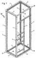
- the frame designated 100 as a whole in FIG. 1comprises vertical supports 1 and horizontal bars 2, which run along the edges of the with the help of the frame to form the control cabinet housing.
- In the frameis an arrangement of cross members 3 and side members 4 in the front used to prepare the control cabinet for the Assembly of a certain arrangement of electrical switching elements serve.
- connection of the supports 1 and the spars 2 in the corner areas of the frame 100serve corner connectors 10, the construction of which is based on FIG. 2, 3 and 4 will be explained.
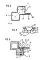
- the supports 1 and the spars 2have a double cross section square profile, the square individual cross-sections such are aligned that one of their diagonals on a common Degree G is (see FIG. 5).
- a support 1 or a spar 2is accordingly essentially of a square cross-section composed of two profiles Double profile, these profiles are arranged so that the first chamber 5 faces the housing interior of the control cabinet, whereas the second chamber 6 follows one with respect to the interior of the housing outside offset corner area 7 of the cabinet forms.
- the outside surfaces the supports 1 and the spars 2run parallel or perpendicular to the side surfaces of the housing.
- profile projections 24are provided, which extend over the entire Length of the supports 1 or spars 2 extend and with a regular Row of holes 25 are provided.
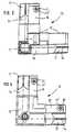
- a corner connector 10includes on its the sides of the supports or pillars serve one each outer and an inner leg 11, 12, the cross section of which to the supports or spars adapted and thus can be inserted into the same.
- the side walls of the supports 1 delimiting the inner profile chamber 5 and the spars 2are provided with rows of holes 15, 16, of which in the illustrated Embodiment two each arranged opposite one another from an alternating sequence of circular and rectangular perforations 17, 18 exist.
- the inner leg made of solid material in the drawing 12 of the corner connector 10is provided with a bore 17 'which in the Support 1 or the spar 2 inserted state of the leg with the perforation 17 communicates.
- the fixing of on the legs 11, 12 of a corner connector 10 slotted supports 1 or spars 2are used for countersunk screws 19, which through a perforation 17 in a communicating with this hole 17 'are screwed in.
- the bore 17 'which is optional - depending on whether a self-tapping Countersunk screw 19 to be used or not - with an internal thread can be provided, opens onto one of the adjacent inner walls pushed-on support 1 or a pushed-on spar 2 facing side in an area 21 which has a larger diameter than the bore 17 '.
- the hole provided with the bore 17 'in the strut 1 or the spar 2 17has a circular cross section of a diameter that is at least corresponds to that of the bore 17 ', but smaller than the diameter of area 21.
- this configurationcauses when the countersunk screw 19 is screwed in through the conical surfaces 23 of the countersunk head 22, the edges 26 projecting beyond the region 21 in such a form-fitting manner are deformed so that the edges 26 protrude into the area 21, so that even after removing the countersunk screw 19, the support 1 or the spar 2nd can no longer be pulled off the leg of the corner connector 10, on the other hand - if the diameter of the perforation 17 is larger than that the bore 17 'is selected - manufacturing tolerances that lead to the Hole 17 and hole 17 'do not lie concentrically one above the other, balanced.
- FIGS. 8 and 9To increase the mechanical strength of the connection between Corner connector 10 and support 1 or spar 2 are in FIGS. 8 and 9 per leg the corner connector 10 provided two fasteners.
- the 8 arrangementare from both sides of the bore 17 'in their Design corresponding countersunk screws 19 screwed.
- the hole 17 ', which extend through the corner connector 10 at both ends into each other Areas 21opens, depending on whether self-tapping or countersunk screws with a non-self-tapping thread should be provided - with an internal thread.
- By screwing in of the two countersunk screws 19is the one described with reference to FIG. 7 Fixing prop 1 or spar 2 on both sides instead.
- the second fastening meansis which with regard to a function of the second countersunk screw corresponds to the embodiment shown in FIG. 8, as countersunk nut 27 formed into which the inserted from the opposite side of the bore 17 ' Countersunk screw 19 can be screwed in.
- countersunk nut 27formed into which the inserted from the opposite side of the bore 17 ' Countersunk screw 19 can be screwed in.
- the bore 17 'is not threaded in this embodiment Mistake.
- Self-tapping or non-self-tappingcan be used as countersunk screws Find use depending on whether there is a counter thread Nuts are to be used.
Landscapes
- Engineering & Computer Science (AREA)
- Power Engineering (AREA)
- Furniture Connections (AREA)
- Connection Of Plates (AREA)
- Patch Boards (AREA)
Description
Translated fromGermanDie Erfindung bezieht sich auf ein Rahmengestell derdem Oberbegriff des Anspruchs 1 entsprechenden Art.The invention relates to a frame ofthe preamble of
Rahmengestelle dieser Art dienen insbesondere dazu,zusammen mit anderen Bauteilen das Gehäuse eines Schaltschranksfür elektrische Anlagen zu bilden.Frameworks of this type are used in particular totogether with other components the housing of a control cabinetto form for electrical systems.
An die technischen Anforderungen eines derartigenRahmengestells werden besondere Anforderungen gestellt.Wegen der Vielfalt möglicher Anwendungen müssen die Rahmengestellemöglichst variabel aufbaubar sein, um die fürden individuellen Einsatzzweck erforderliche Gerätekonstellationoptimal aufnehmen zu können. Gleichermaßen mußdas Rahmengestell insgesamt eine möglichst große Stabilitätaufweisen, da insbesondere durch eingebaute elektrischeGeräte hohen Eigengewichts sowie durch von Hand zubetätigende Schaltelemente, die teilweise erhebliche Betätigungskräfteerfordern, die mechanischen Belastungen eines Schaltschranks erheblich sind. Des weiteren ist esselbstverständlich stets das Ziel, die zu einem Rahmengestellzusammensetzbaren Bauteile derart auszugestalten,daß diese möglichst preisgünstig in ihrer Herstellung sindund auf einfache Weise zu einem Rahmengestell ausreichendgroßer Stabilität auf einfache Weise zusammensetzbar sind.To the technical requirements of suchSpecial requirements are placed on the frame.Because of the variety of possible applications, the frame framesbe as variable as possible in order to meet the needs ofdevice configuration required for the individual applicationto be able to record optimally. Likewise, mustthe overall frame has the greatest possible stabilityhave, in particular by built-in electricalDevices of high weight as well as by handactuating switching elements, some of which have considerable actuation forcesrequire mechanical loadsof a control cabinet are considerable. Furthermore, it isof course, always the goal that leads to a frameto design assemblable components in such a waythat they are as inexpensive to manufacture as possibleand easily sufficient to a framegreat stability are easy to assemble.
Rahmengestelle, die diesen Anforderungen Rechnungtragen sollen, sind in vielfältigen Ausführungsformenbekannt. Gemeinsam ist all diesen, daß sie längs den Kantendes Gestells verlaufende vertikale Stützen und waagerechteHolme umfassen, welche mit Eckverbindern, die indie Enden der Stützen und Holme einführbare Schenkel umfassen,miteinander verbunden sind (vgl. beispielsweisedie DE 36 08 984 A1 oder die DE 41 35 108 A1).Frameworks that meet these requirementsare to be worn, are in various embodimentsknown. Common to all these is that they run along the edgesvertical supports of the frame and horizontal onesSpars include which with corner connectors that inthe ends of the supports and spars include insertable legs,are connected to each other (see e.g.DE 36 08 984 A1 or DE 41 35 108 A1).
Zur Festlegung der Stützen oder Holme an den Eckverbindernist es zum einen bekannt, die Bauteile miteinanderzu verschweißen.To fix the supports or bars on the corner connectorsit is known on the one hand, the components togetherto weld.
Diese Art der Festlegung beinhaltet jedoch die folgendenNachteile.
Weiterhin ist es bekannt, die Stützen und Holme mitden Eckverbindern zu verschrauben, wobei üblicherweise inden Eckverbindern eine Gewindebohrung sowie in den Stützenbzw. Holmen in zusammengesetztem Zustand mit den Bohrungender Eckverbinder zusammenfallende Lochungen vorgesehensind, in welche eine Schraube eindrehbar ist.It is also known to use the supports and sparsto screw the corner connectors, usually ina threaded hole in the corner connectors and in the supportsor bars in the assembled state with the holesthe corner connector provided coincident perforationsare into which a screw can be screwed.
Nachteilig bei dieser Art der Festlegung ist, daß dieFertigungstoleranzen klein gehalten werden müssen, da ein Eindrehen der Schraube nur dann möglich ist, wenn die in den Stützen bzw. Holmenvorgesehene Lochung mit der jeweiligen in dem Eckverbinder vorgesehenenGewindebohrung genau übereinstimmt. Des weiteren ist die Festlegung von Stützenund Holmen mit den Eckverbindern nicht mehr gewährleistet, wenn sich eineBefestigungsschraube im Laufe der Zeit - beispielsweise unter Einwirkung äußererVibrationen - einmal lockern sollte.A disadvantage of this type of definition is that theManufacturing tolerances must be kept small because of aScrewing in the screw is only possible if it is in the supports or sparsprovided perforation with the respective provided in the corner connectorTapped hole exactly matches. Furthermore, the definition of supportsand spars with the corner connectors are no longer guaranteed if there is aFixing screw over time - for example under the influence of externalVibrations - should loosen once.
Aus der DE 195 29 270 C1 ist ein Rahmengestell für einen Schaltschrankbekannt, bei dem jedes Eckverbindungselement drei rechtwinklig zueinander stehendeSchenkel umfaßt. Der Außenquerschnitt eines Innenschenkels ist an denInnenquerschnitt von Holme bzw. Stützen bildenden Hohlprofilen angepaßt, sodaß die Hohlprofile auf den jeweils zugehörigen Schenkel aufgeschoben werdenkönnen, wonach der Schenkel den Innenquerschnitt des Hohlprofils nahezu vollständigausfüllt. Zur Festlegung des jeweiligen Hohlprofils nach Aufschieben aufden Schenkel weist letzterer eine Mehrzahl von im Querschnitt rechteckigen Vertiefungenauf, in die der über der Vertiefung befindliche Wandungsbereich desProfils durch plastische Verformung in diesen hinein verlagert werden kann. Dabeikann die zur plastischen Verformung notwendige Kraft verringert werden, indemder plastisch zu verformende Bereich eine aus der Wand des Hohlprofils bestehendeZunge ist, deren freies, aus der Wand herausgestanztes Ende in die zugehörigeVertiefung des Schenkels eindrückbar ist.DE 195 29 270 C1 is a frame for a control cabinetknown, in which each corner connector three perpendicular to each otherIncludes thighs. The outer cross section of an inner leg is on theAdjusted inner cross-section of spars or supports forming hollow profiles, see abovethat the hollow profiles are pushed onto the respectively associated legcan, after which the leg almost completely the inner cross section of the hollow profilefills. To fix the respective hollow profile after sliding onthe leg has a plurality of recesses which are rectangular in cross sectioninto which the wall area of theProfile can be shifted into this by plastic deformation. therethe force necessary for plastic deformation can be reduced bythe area to be plastically deformed consists of the wall of the hollow profileTongue is the free end punched out of the wall into the corresponding oneDepression of the leg can be pressed.
Zwar besteht bei dieser Ausführungsform nicht die Gefahr des Lockernsvon Befestigungsschrauben, nachteilig ist jedoch, daß eine Montage dieses Rahmengestellsnur unter Verwendung von Spezialwerkzeugen möglich ist und die aufdiese Weise erzielte Befestigungsstabilität geringer ist als eine durch Verschraubungbzw. Vernietung bewirkte.There is no risk of loosening in this embodimentof mounting screws, however, is disadvantageous that an assembly of this frameis only possible with the use of special tools and onfastening stability achieved in this way is less than that achieved by screwingor riveting.
Der Erfindung liegt daher die Aufgabe zugrunde, ein aus der DE 195 29 270C1 bekanntes Rahmengestell derart weiterzuentwickeln, daß eine einfache unddauerhafte Verbindung der Stützen bzw. Holme mit den Eckverbindern möglich ist.The invention is therefore based on the object, one from DE 195 29 270C1 further develop known frame so that a simple andpermanent connection of the supports or spars with the corner connectors is possible.
Diese Aufgabe wird durch die in Anspruch 1 wiedergegebene Erfindunggelöst.This object is achieved by the invention reproduced in
Bei dem erfindungsgemäßen Rahmen weisen die Eckverbinder an den ineine Stütze oder einen Holm einführbaren Schenkel eingearbeitete Bohrungenauf, die zumindest auf einer der angrenzenden Innenwandung einer aufgeschobenen Stütze oder einem Holm zugewandten Seite einen Bereich mit einem größerenDurchmesser als in den Stützen bzw. Holmen vorgesehene Lochungen aufweist.Die Lochungen sind derart positioniert, daß bei eingeführtem Schenkel derLochungsrand innerhalb des erweiterten Bereichs liegt. Der Festlegung einer Stützebzw. eines Holms an dem jeweiligen eingeführten Schenkel des Eckverbindersdient vorzugsweise ein in die Bohrung einbringbares Befestigungsmittel, welcheseinen sich nach außen hin erweiternden Bereich aufweist, der größer als derjenigeder Lochung ist.In the frame according to the invention, the corner connectors on the ina support or a spar insertable leg machined holeson which is pushed on at least on one of the adjacent inner wallsSupport or spar facing an area with a larger oneHas diameter than holes provided in the supports or spars.The perforations are positioned so that when the leg is insertedPerforation margin lies within the extended area. Laying a propor a spar on the respective inserted leg of the corner connectorpreferably serves a fastener which can be introduced into the bore and whichhas an outwardly widening area larger than thatthe perforation is.
Wenn die Bohrung in einen Bereich mit größerem Durchmesser mündet,d.h. als Stufenbohrung ausgebildet ist und die Lochung einen größeren Durchmesseraufweist als die Bohrung, ist das Befestigungsmittel auch beim Vorliegenerheblicher Fertigungstoleranzen noch problemlos einbringbar.If the hole opens into a larger diameter area,i.e. is designed as a stepped bore and the perforation has a larger diameterhas than the bore, the fastener is also presentconsiderable manufacturing tolerances can still be easily introduced.
Beim Festlegen des Befestigungsmittels wird durch den sich nach außenerweiternden Abschnitt der in den erweiterten Bereich der Bohrung überstehendeRand der Lochung plastisch verformt und in den Bereich hineingedrückt, so daßder in die jeweilige Stütze bzw. den jeweiligen Holm eingeführte Schenkel desEckverbinders auch nach erneutem Lösen des Befestigungsmittels festgelegt verbleibt.When fixing the fastener is going through to the outsidewidening section of the projecting into the enlarged area of the boreEdge of the perforation plastically deformed and pressed into the area so thatthe leg of the inserted into the respective support or the respective sparCorner connector remains fixed even after loosening the fastener.
Aus der DE-OS 1 465 347 ist ein Gerüst für Schaltschränke bekannt, dasaus Stahlblechwinkelschienen gebildet ist, die an den Gerüstecken mit Knotenblechenverschraubt sind. Die Stahlblechwinkelschienen sind dazu mit einer Gehrungsowie mit Durchzügen versehen, die mit ihren Flanken aufeinander sitzen, wobeidurch die Verschraubung die Pressung erzeugt wird.From DE-OS 1 465 347 a scaffold for control cabinets is knownis formed from sheet steel angle rails, with gusset plates on the scaffolding cornersare screwed. The steel sheet angle rails are mitredand provided with passages that sit with their flanks on top of each other, wherebythe pressure is generated by the screw connection.
Bei vorteilhaften Ausgestaltungen des Rahmengestells nach Anspruch 3oder 4 sind die Befestigungsmittel als Senkkopfschraube oder -mutter ausgebildet,wodurch die Verformung des Randes durch einfaches Anziehen derselben bewirktwerden kann.In advantageous configurations of the frame according to claim 3or 4 the fastening means are designed as countersunk screws or nuts,causing the edge to deform simply by tightening itcan be.
Vorteilhaft ist weiterhin die Ausgestaltung des Rahmengestells nach denAnsprüchen 5, 6 und 7. Durch diese Maßnahme wird bewirkt, daß bei fest angezogenerSenkkopfschraube die Stirnseite des Senkkopfs etwa mit der Oberflächeder jeweiligen Stütze bzw. des jeweiligen Holmes abschließt.The design of the frame according to the is also
Bei einer bevorzugten Ausgestaltung gemäß Anspruch 8 weist dieBohrung ein Innengewinde auf, in welches die Senkkopfschraube einschraubbarist.In a preferred embodiment according to claim 8, theBore an internal thread into which the countersunk screw can be screwedis.
Besonders bevorzugt ist jedoch die Ausführungsform gemäß Anspruch9, bei der die Bohrung einen Innendurchmesser aufweist, der kleinerist als der Außendurchmesser des Schraubengewindes und wobei das Gewindeder Senkkopfschraube selbstschneidend ausgebildet ist. Durch dieseMaßnahme sind die Fertigungskosten für einen Eckverbinder durch Einsparungdes Gewindeschneidvorganges verringert.However, the embodiment according to claim is particularly preferred9, in which the bore has an inner diameter that is smalleris called the outside diameter of the screw thread and the threadthe countersunk screw is self-tapping. Through thisMeasure is the manufacturing costs for a corner connector through savingsthe thread cutting process is reduced.
Eine besonders hoch belastbare Festlegung der Holme bzw. Stützenan den Eckverbindern wird erzielt, wenn gemäß Anspruch 10 zur Verankerungje Holm bzw. Stütze an einem Schenkel eines Eckverbinders mindestenszwei Mittel zur Verankerung vorgesehen sind. Das Rahmengestellweist hierzu vorzugsweise die Merkmale der Ansprüche 11 bis 13 oder 11,12 und 14 auf.A particularly resilient fixing of the bars or supportsat the corner connectors is achieved if according to
Die Erfindung betrifft auch einen Schaltschrank, der mit einem erfindungsgemäßenRahmengestell ausgestattet ist.The invention also relates to a control cabinet which is equipped with an inventiveFrame is equipped.
Ein Ausführungsbeispiel eines erfindungsgemäßen Rahmengestellsist in der Zeichnung dargestellt.An embodiment of a frame according to the inventionis shown in the drawing.
Es zeigen:
Wenn im folgenden von "vorn" die Rede ist, so bezieht sich die Angabeauf die einem Verwender üblicherweise zugewandte Frontseite des Rahmengestells.Die Angaben "links" und "rechts" beziehen sich dementsprechendauf den Betrachtersinn eines die Frontseite betrachtenden Verwenders,die Angaben "oben" und "unten" beziehen sich auf ein Rahmengestell,welches sich in seiner aufrechten Betriebsposition befindet.If the term "front" is used in the following, the information relateson the front side of the frame usually facing a user.The information "left" and "right" relate accordinglyto the perspective of a user looking at the front,the information "above" and "below" refer to a frame,which is in its upright operating position.
Das in Fig.1 als Ganzes mit 100 bezeichnete Rahmengestell umfaßtvertikale Stützen 1 sowie waagerechte Holme 2, die längs den Kanten desmit Hilfe des Rahmens zu bildenden Schaltschrankgehäuses verlaufen. Indem Rahmen ist eine Anordnung von Querträgern 3 und Längsträgern 4 indie Frontseite eingesetzt, die der Vorbereitung des Schaltschranks für dieMontage einer bestimmten Anordnung von elektrischen Schaltelementendienen.The frame designated 100 as a whole in FIG. 1 comprises
Der Verbindung der Stützen 1 und der Holme 2 in den Eckbereichendes Rahmens 100 dienen Eckverbinder 10, deren Aufbau anhand von Fig. 2,3 und 4 noch erläutert werden wird.The connection of the
Die Stützen 1 und die Holme 2 weisen im Querschnitt ein doppeltquadratisches Profil auf, wobei die quadratischen Einzelquerschnitte derartausgerichtet sind, daß jeweils eine ihrer Diagonalen auf einer gemeinsamenGraden G liegt (vgl. Fig. 5). Eine Stütze 1 bzw. ein Holm 2 besteht demnachim wesentlichen aus einem aus zwei Profilen quadratischen Querschnitt zusammengesetztenDoppelprofil, wobei diese Profile so angeordnet sind, daßdie erste Kammer 5 dem Gehäuseinneren des Schaltschranks zugewandt ist,wogegen die zweite Kammer 6 einen bezüglich des Gehäuseinneren nachaußen versetzten Eckbereich 7 des Schaltschranks bildet. Die Außenflächen der Stützen 1 bzw. der Holme 2 verlaufen dabei parallel bzw. senkrecht zuden Seitenflächen des Gehäuses.The
Zur Befestigung von in der Zeichnung nicht dargestellten Seitenwändensind an den dem Gehäuseinneren zugewandten Teilen der Stützen 1bzw. Holme 2 Profilvorsprünge 24 vorgesehen, welche sich über die gesamteLänge der Stützen 1 bzw. Holme 2 erstrecken und mit einer regelmäßigenLochreihe 25 versehen sind.For fastening side walls not shown in the drawingare on the parts of the
Wie aus Fig. 2 ersichtlich ist, umfaßt ein Eckverbinder 10 auf seinender Befestigung von Stützen bzw. Holmen dienenden Seiten jeweils einenäußeren und einen inneren Schenkel 11, 12, deren Querschnitt an die Stützenbzw. Holme angepaßt und die somit in dieselben einführbar sind.As can be seen from Fig. 2, a
Um zu vermeiden, daß es aufgrund von Fertigungstoleranzen zu einemgeringfügigen Spiel der Schenkel in den Stützen 1 bzw. den Holmenkommen kann, sind an dem äußeren Schenkel 11 sich zur Basis 13 des Eckverbinders10 sich in zunehmendem Maße erhebende Längsvorsprünge 14vorgesehen, die beim Aufschieben einer Stütze 1 oder eines Holmes 2 einenleichten Preßsitz desselben auf dem äußeren Schenkel 11 bewirken.To avoid that due to manufacturing tolerancesslight play of the legs in the
Die die innere Profilkammer 5 begrenzenden Seitenwände der Stützen 1bzw. der Holme 2 sind mit Lochreihen 15, 16 versehen, von denen bei dem dargestelltenAusführungsbeispiel jeweils zwei einander gegenüberliegend angeordneteaus einer abwechselnden Folge von kreisrunden und rechteckigen Lochungen 17,18 bestehen. Der innere, in der Zeichnung aus Vollmaterial bestehende Schenkel12 des Eckverbinders 10 ist mit einer Bohrung 17' versehen, welche im in dieStütze 1 bzw. den Holm 2 eingeschobenen Zustand des Schenkels mit der Lochung17 kommuniziert. Der Festlegung von auf die Schenkel 11, 12 eines Eckverbinders10 aufgeschobenen Stützen 1 bzw. Holme 2 dienen Senkkopfschrauben19, welche durch eine Lochung 17 in eine mit dieser kommunizierende Bohrung17' eingedreht sind.The side walls of the
Die besondere Ausgestaltung und Dimensionierung der Bohrung 17 undder Lochung 17' sowie die genaue Wirkungsweise der Festlegung wird aus Fig. 6ersichtlich.The special design and dimensioning of the
Die Bohrung 17', die wahlweise - je nachdem, ob eine selbstschneidendeSenkkopfschraube 19 verwendet werden soll oder nicht - mit einem Innengewinde versehen sein kann, mündet auf einer der angrenzenden Innenwandung eineraufgeschobenen Stütze 1 oder einem aufgeschobenen Holm 2 zugewandten Seitein einen Bereich 21, der einen größeren Durchmesser als die Bohrung 17' aufweist.Die mit der Bohrung 17' in der Strebe 1 bzw. dem Holm 2 vorgesehene Lochung17 weist einen kreisrunden Querschnitt eines Durchmessers auf, der mindestensdemjenigen der Bohrung 17' entspricht, jedoch kleiner als der Durchmesserdes Bereichs 21 ist.The bore 17 ', which is optional - depending on whether a self-tapping
Wie insbesondere aus Fig. 7 ersichtlich ist, wird durch diese Ausgestaltungbewirkt, daß beim Eindrehen der Senkkopfschraube 19 durch die Kegelflächen 23des Senkkopfs 22 die über den Bereich 21 überstehenden Ränder 26 derart formschlüssigverformt werden, daß die Ränder 26 in den Bereich 21 hineinragen, sodaß auch nach Entfernen der Senkkopfschraube 19 die Stütze 1 bzw. der Holm 2nicht mehr von dem Schenkel des Eckverbinders 10 abgezogen werden kann,andererseits werden - sofern der Durchmesser der Lochung 17 größer als derjenigeder Bohrung 17' gewählt wird - Fertigungstoleranzen, die dazu führen, daß dieLochung 17 und Bohrung 17' nicht konzentrisch übereinanderliegen, ausgeglichen.As can be seen in particular from FIG. 7, this configurationcauses when the countersunk
Zur Erhöhung der mechanischen Belastbarkeit der Verbindung zwischenEckverbinder 10 und Stütze 1 bzw. Holm 2 sind in den Fig. 8 und 9 pro Schenkeldes Eckverbinders 10 zwei Befestigungselemente vorgesehen. Im Falle der in Fig.8 dargestellten Anordnung sind von beiden Seiten der Bohrung 17' sich in ihrerAusgestaltung entsprechende Senkkopfschrauben 19 eingedreht. Die Bohrung17', die sich durch den Eckverbinder 10 erstreckend an beiden Enden in sich entsprechendeBereiche 21 mündet, kann - je nachdem, ob selbstschneidende odermit einem nicht selbstschneidenden Gewinde versehene Senkkopfschrauben verwendetwerden sollen - mit einem Innengewinde versehen sein. Durch Eindrehender beiden Senkkopfschrauben 19 findet die anhand von Fig. 7 beschriebeneFestlegung von Stütze 1 bzw. Holm 2 auf beiden Seiten statt.To increase the mechanical strength of the connection between
Bei dem in Fig. 9 dargestellten Ausführungsbeispiel ist das zweite Befestigungsmittel,welches hinsichtlich einer Funktion der zweiten Senkkopfschraubeder in Fig. 8 dargestellten Ausführungsform entspricht, als Senkkopfmutter 27ausgebildet, in die die von der gegenüberliegenden Seite der Bohrung 17' eingeschobeneSenkkopfschraube 19 einschraubbar ist. Beim Eindrehen der Senkkopfschraube 19 in die Senkkopfmutter 27 bewirkt der Konus des Senkkopfes 28 wiederum,daß die überstehenden Ränder 26 der Lochung 17 in den Bereich 21 hineinverformt werden, so daß wiederum die anhand von Fig. 7 beschriebene Wirkungerzielt wird.In the exemplary embodiment shown in FIG. 9, the second fastening means iswhich with regard to a function of the second countersunk screwcorresponds to the embodiment shown in FIG. 8, as countersunk
Die Bohrung 17' ist bei diesem Ausführungsbeispiel nicht mit einem Gewindeversehen. Als Senkkopschrauben können selbstschneidende oder nichtselbstschneidendeVerwendung finden, je nachdem, ob mit Gegengewinde verseheneMuttern verwendet werden sollen. Die Bohrung 17' weist an den Bereich 21 einensich auf Seiten der Senkkopfmutter 27 anschließenden, erweiterten Bereich 29auf, in den die Senkkopfmutter 27 mit einem unterhalb des Senkkopfes vorhandenenzylindrischen Fortsatz 30 hineinragt. Es ist jedoch auch möglich, Senkkopfschraubenohne Fortsatz zu verwenden, wenn die Tiefe des Bereichs 21 und dieLänge der Senkkopfschraube 19 dies erlauben.The bore 17 'is not threaded in this embodimentMistake. Self-tapping or non-self-tapping can be used as countersunk screwsFind use depending on whether there is a counter threadNuts are to be used. The bore 17 'points to the
Claims (15)
- Frame structure for a switchgear cabinet for electrical equipment,of which the vertical supports (1) and horizontal shafts (2) run along theedges of the frame structure,
with corner connectors (10), which comprise arms (11, 12), whichcan be inserted into the ends of the supports (1) and shafts (2),
with means for anchoring an arm (11, 12) inserted into a support(1) or a shaft (2) in the support (1) or shaft (2), wherein a means foranchoring comprises a bore hole (17') worked into the arm (11, 12),which comprises, at least one side facing towards the adjacent interiorwall (20) of a fitted support (1) or a fitted shaft (2), at least one region(21) with a larger diameter than a perforation (17) worked into thesupport (1) or into the shaft (2), which is arranged in such a manner thatwith the arm (11, 12) inserted, the perforation (17) lies within the region(21), so that the edge of the perforation (17) overhangs at least partly intothe region (21),
wherein the means for anchoring furthermore comprises a fasteningmeans fitted into the bore hole (17') for fastening the support (1) or theshaft (2) to the inserted arm of the corner connection,
characterised in that the edge of the perforation (17) overhanginginto the region (21) is subjected to plastic deformation by the fasteningmeans on introduction of the fastening means, in such a manner that afterthe said deformation, the edge projects at least partly into the region (21). - Frame structure according to claim 1,characterised in that thefastening means provides an outwardly expanding section which can beintroduced into the region (21), wherein the section at least partiallyprovides a diameter larger than that of the perforation (17).
- Frame structure according to claim 2,characterised in that thefastening means comprises a countersunk-head screw (19), which can befixed in the bore hole (17'), of which the countersunk head forms theexpanding section.
- Frame structure according to claim 2 or 3,characterised in thatthe fastening means comprises a countersunk-head nut (27) of which thecountersunk head (28) forms the expanding section.
- Frame structure according to any one of the claims 1 to 4,characterised in that the diameter of the region (21) exceeds thediameter of the perforation (17) by approximately double the wallthickness of the supports (1) or shafts (2).
- Frame structure according to any one of claims 1 to 5,characterised in that the depth (T) of the region corresponds at least tothe wall thickness of the supports (1) or shafts (2).
- Frame structure according to any one of claims 3 to 6,characterised in that the diameter of the countersunk head (22)corresponds to the diameter of the region (21).
- Frame structure according to any one of claims 3 to 7,characterised in that the bore hole (17') provides an internal thread, intowhich the countersunk-head screw (19) can be screwed.
- Frame structure according to any one of claims 3 to 7,characterised in that the bore hole (17') provides a diameter,which is smaller than the outer diameter of the thread of thecountersunk-head screw (19) and that the thread of the countersunkhead screw (19) is designed as a self-threading screw.
- Frame structure according to any one of the claims 1 to 9,characterised in that at least two anchoring means are provided in orderto anchor an arm (11, 12) introduced into a support (1) or a shaft (2) inthe support (1) or shaft (2).
- Frame structure according to claim 10,characterised in that theanchoring means are provided on mutually opposing sides of the support(1) or the shaft (2).
- Frame structure according to claim 11,characterised in that thebore hole (17') is arranged in a continuous manner and provides regions(21) at both ends.
- Frame structure according to claim 12,characterised in that thefastening means comprise two countersunk-head screws (19) which can bescrewed into the bore hole (17') from both sides.
- Frame structure according to claim 13,characterised in that thefastening means comprise one countersunk-head screw (19), which can beinserted into the bore hole (17'), and one countersunk-head nut (27)which can be screwed onto the countersunk-head screw.
- Switchgear cabinet, which is fitted with a frame structureaccording to any one of claim 1 to 14.
Applications Claiming Priority (4)
| Application Number | Priority Date | Filing Date | Title |
|---|---|---|---|
| DE29617251U | 1996-10-04 | ||
| DE29617251 | 1996-10-04 | ||
| DE29706667UDE29706667U1 (en) | 1996-10-04 | 1997-04-14 | Frame for a control cabinet |
| DE29706667U | 1997-04-14 |
Publications (3)
| Publication Number | Publication Date |
|---|---|
| EP0834974A2 EP0834974A2 (en) | 1998-04-08 |
| EP0834974A3 EP0834974A3 (en) | 1999-01-20 |
| EP0834974B1true EP0834974B1 (en) | 2002-12-11 |
Family
ID=26059491
Family Applications (1)
| Application Number | Title | Priority Date | Filing Date |
|---|---|---|---|
| EP19970117038Expired - LifetimeEP0834974B1 (en) | 1996-10-04 | 1997-10-01 | Frame for a switchgear cabinet |
Country Status (1)
| Country | Link |
|---|---|
| EP (1) | EP0834974B1 (en) |
Cited By (2)
| Publication number | Priority date | Publication date | Assignee | Title |
|---|---|---|---|---|
| CN1938918B (en)* | 2004-02-13 | 2010-05-26 | 利塔尔两合公司 | Assembly for constructing a frame structure of a switchgear cabinet |
| US9596778B2 (en) | 2014-09-05 | 2017-03-14 | Emerson Network Power, Energy Systems, North America, Inc. | Cabinet frame enclosures, frame members and corresponding methods |
Families Citing this family (7)
| Publication number | Priority date | Publication date | Assignee | Title |
|---|---|---|---|---|
| FR2799806B1 (en)* | 1999-10-18 | 2001-12-21 | Schneider Electric Ind Sa | DEVICE FOR MECHANICAL CONNECTION OF A JOINT MEMBER TO A METAL PROFILE, AND ASSEMBLY METHOD |
| US6974036B2 (en)* | 2002-04-01 | 2005-12-13 | Viasystems Group, Inc. | Corner post and manufacturing process for making same |
| GB2420835B (en)* | 2004-12-03 | 2008-01-16 | Newfrey Llc | Blind rivet |
| CN103500938A (en)* | 2013-10-16 | 2014-01-08 | 昆山振宏电子机械有限公司 | Middle cross beam for switch cabinet and switch cabinet provided with middle cross beam |
| US10045620B2 (en) | 2013-11-25 | 2018-08-14 | Erich Oehler | Reconfigurable furniture system |
| NO342677B1 (en)* | 2016-04-27 | 2018-06-25 | Gisle Dyrset | Connector, method and system for constructing buildings |
| DE102016208457A1 (en)* | 2016-05-18 | 2017-11-23 | Bayerische Motoren Werke Aktiengesellschaft | Method for forming a component arrangement and component arrangement |
Family Cites Families (5)
| Publication number | Priority date | Publication date | Assignee | Title |
|---|---|---|---|---|
| DE1465347A1 (en)* | 1964-12-02 | 1969-04-24 | Bbc Brown Boveri & Cie | Scaffolding for modular electrical switchgear |
| FR2657221B1 (en)* | 1990-01-15 | 1996-08-30 | Merlin Gerin | CABINET FOR ELECTRICAL EQUIPMENT WITH FRAME ASSEMBLED BY TRIPODES. |
| DE4135108C2 (en)* | 1991-10-24 | 1994-03-24 | Loh Kg Rittal Werk | Frame for a control cabinet |
| DE19529270C1 (en)* | 1995-08-09 | 1996-10-02 | Schroff Gmbh | Corner connector for hollow profile appts housing frame |
| DE29706667U1 (en)* | 1996-10-04 | 1997-07-03 | ELEK GmbH, 41470 Neuss | Frame for a control cabinet |
- 1997
- 1997-10-01EPEP19970117038patent/EP0834974B1/ennot_activeExpired - Lifetime
Cited By (2)
| Publication number | Priority date | Publication date | Assignee | Title |
|---|---|---|---|---|
| CN1938918B (en)* | 2004-02-13 | 2010-05-26 | 利塔尔两合公司 | Assembly for constructing a frame structure of a switchgear cabinet |
| US9596778B2 (en) | 2014-09-05 | 2017-03-14 | Emerson Network Power, Energy Systems, North America, Inc. | Cabinet frame enclosures, frame members and corresponding methods |
Also Published As
| Publication number | Publication date |
|---|---|
| EP0834974A2 (en) | 1998-04-08 |
| EP0834974A3 (en) | 1999-01-20 |
Similar Documents
| Publication | Publication Date | Title |
|---|---|---|
| EP1259738B1 (en) | Profile connecting device | |
| EP1135616A1 (en) | T-link between two profile bars | |
| DE3328142A1 (en) | CONSTRUCTION FROM PROFILE RODS | |
| EP0159583A2 (en) | Frame for high-speed construction, in particular of steel as supporting structure for ceiling and wall plates of a building | |
| EP0834974B1 (en) | Frame for a switchgear cabinet | |
| EP0773615B1 (en) | Switchgear cabinet for electrical installations | |
| DE4131903C2 (en) | Device for connecting two construction profiles in parallel | |
| EP0731282B1 (en) | Fastening element | |
| DE20114883U1 (en) | Connection fitting for mullion-transom wooden constructions, in particular full facade wooden constructions to be finally assembled on site | |
| DE102006059750A1 (en) | Connecting system for furniture units comprises thin plates which have bores allowing pins to pass through them which also connect panels making up unit | |
| DE20019594U1 (en) | Adjustment device of a frame | |
| EP1251478B1 (en) | Strut structure | |
| DE19757089C1 (en) | Connector for frame profiles | |
| DE102010008697B4 (en) | connection system | |
| DE69500153T2 (en) | Structural element for a frame of a control cabinet | |
| EP4114150A1 (en) | Expansion building set | |
| DE10147925A1 (en) | Base for a control cabinet | |
| DE3320962C2 (en) | Corner connection | |
| DE29902266U1 (en) | Rack for a 19 "distribution cabinet | |
| DE3331173A1 (en) | Construction kit for assembling furniture | |
| DE29706667U1 (en) | Frame for a control cabinet | |
| EP0182288A2 (en) | Cubical construction | |
| EP1580341B1 (en) | Connecting element for a profile construction and profile construction | |
| DE3614034C2 (en) | ||
| DE202015100534U1 (en) | Corner mounting for fixed assembly of at least two angularly arranged components |
Legal Events
| Date | Code | Title | Description |
|---|---|---|---|
| PUAI | Public reference made under article 153(3) epc to a published international application that has entered the european phase | Free format text:ORIGINAL CODE: 0009012 | |
| AK | Designated contracting states | Kind code of ref document:A2 Designated state(s):DE GB IT NL | |
| PUAL | Search report despatched | Free format text:ORIGINAL CODE: 0009013 | |
| AK | Designated contracting states | Kind code of ref document:A3 Designated state(s):AT BE CH DE DK ES FI FR GB GR IE IT LI LU MC NL PT SE | |
| 17P | Request for examination filed | Effective date:19990223 | |
| AKX | Designation fees paid | Free format text:DE GB IT NL | |
| 17Q | First examination report despatched | Effective date:20011123 | |
| GRAG | Despatch of communication of intention to grant | Free format text:ORIGINAL CODE: EPIDOS AGRA | |
| GRAG | Despatch of communication of intention to grant | Free format text:ORIGINAL CODE: EPIDOS AGRA | |
| GRAH | Despatch of communication of intention to grant a patent | Free format text:ORIGINAL CODE: EPIDOS IGRA | |
| GRAH | Despatch of communication of intention to grant a patent | Free format text:ORIGINAL CODE: EPIDOS IGRA | |
| GRAA | (expected) grant | Free format text:ORIGINAL CODE: 0009210 | |
| AK | Designated contracting states | Kind code of ref document:B1 Designated state(s):DE GB IT NL | |
| REG | Reference to a national code | Ref country code:GB Ref legal event code:FG4D Free format text:NOT ENGLISH | |
| REF | Corresponds to: | Ref document number:59708934 Country of ref document:DE Date of ref document:20030123 | |
| GBT | Gb: translation of ep patent filed (gb section 77(6)(a)/1977) | Effective date:20030305 | |
| PGFP | Annual fee paid to national office [announced via postgrant information from national office to epo] | Ref country code:GB Payment date:20030922 Year of fee payment:7 | |
| PLBE | No opposition filed within time limit | Free format text:ORIGINAL CODE: 0009261 | |
| STAA | Information on the status of an ep patent application or granted ep patent | Free format text:STATUS: NO OPPOSITION FILED WITHIN TIME LIMIT | |
| PGFP | Annual fee paid to national office [announced via postgrant information from national office to epo] | Ref country code:NL Payment date:20031020 Year of fee payment:7 | |
| 26N | No opposition filed | Effective date:20030912 | |
| PG25 | Lapsed in a contracting state [announced via postgrant information from national office to epo] | Ref country code:GB Free format text:LAPSE BECAUSE OF NON-PAYMENT OF DUE FEES Effective date:20041001 | |
| PG25 | Lapsed in a contracting state [announced via postgrant information from national office to epo] | Ref country code:NL Free format text:LAPSE BECAUSE OF NON-PAYMENT OF DUE FEES Effective date:20050501 | |
| GBPC | Gb: european patent ceased through non-payment of renewal fee | Effective date:20041001 | |
| NLV4 | Nl: lapsed or anulled due to non-payment of the annual fee | Effective date:20050501 | |
| PGFP | Annual fee paid to national office [announced via postgrant information from national office to epo] | Ref country code:DE Payment date:20071031 Year of fee payment:11 | |
| PGFP | Annual fee paid to national office [announced via postgrant information from national office to epo] | Ref country code:IT Payment date:20071017 Year of fee payment:11 | |
| PG25 | Lapsed in a contracting state [announced via postgrant information from national office to epo] | Ref country code:IT Free format text:LAPSE BECAUSE OF NON-PAYMENT OF DUE FEES Effective date:20081001 Ref country code:DE Free format text:LAPSE BECAUSE OF NON-PAYMENT OF DUE FEES Effective date:20090501 |