EP0834792A2 - Detachable flat panel computer display and support - Google Patents
Detachable flat panel computer display and supportDownload PDFInfo
- Publication number
- EP0834792A2 EP0834792A2EP97307090AEP97307090AEP0834792A2EP 0834792 A2EP0834792 A2EP 0834792A2EP 97307090 AEP97307090 AEP 97307090AEP 97307090 AEP97307090 AEP 97307090AEP 0834792 A2EP0834792 A2EP 0834792A2
- Authority
- EP
- European Patent Office
- Prior art keywords
- display
- support
- display unit
- unit
- system unit
- Prior art date
- Legal status (The legal status is an assumption and is not a legal conclusion. Google has not performed a legal analysis and makes no representation as to the accuracy of the status listed.)
- Granted
Links
Images


Classifications
- G—PHYSICS
- G06—COMPUTING OR CALCULATING; COUNTING
- G06F—ELECTRIC DIGITAL DATA PROCESSING
- G06F1/00—Details not covered by groups G06F3/00 - G06F13/00 and G06F21/00
- G06F1/16—Constructional details or arrangements
- G—PHYSICS
- G06—COMPUTING OR CALCULATING; COUNTING
- G06F—ELECTRIC DIGITAL DATA PROCESSING
- G06F1/00—Details not covered by groups G06F3/00 - G06F13/00 and G06F21/00
- G06F1/16—Constructional details or arrangements
- G06F1/1613—Constructional details or arrangements for portable computers
- G06F1/1615—Constructional details or arrangements for portable computers with several enclosures having relative motions, each enclosure supporting at least one I/O or computing function
- G06F1/1616—Constructional details or arrangements for portable computers with several enclosures having relative motions, each enclosure supporting at least one I/O or computing function with folding flat displays, e.g. laptop computers or notebooks having a clamshell configuration, with body parts pivoting to an open position around an axis parallel to the plane they define in closed position
- G—PHYSICS
- G06—COMPUTING OR CALCULATING; COUNTING
- G06F—ELECTRIC DIGITAL DATA PROCESSING
- G06F1/00—Details not covered by groups G06F3/00 - G06F13/00 and G06F21/00
- G06F1/16—Constructional details or arrangements
- G06F1/1601—Constructional details related to the housing of computer displays, e.g. of CRT monitors, of flat displays
- G—PHYSICS
- G06—COMPUTING OR CALCULATING; COUNTING
- G06F—ELECTRIC DIGITAL DATA PROCESSING
- G06F1/00—Details not covered by groups G06F3/00 - G06F13/00 and G06F21/00
- G06F1/16—Constructional details or arrangements
- G06F1/1613—Constructional details or arrangements for portable computers
- G06F1/1633—Constructional details or arrangements of portable computers not specific to the type of enclosures covered by groups G06F1/1615 - G06F1/1626
- G06F1/1637—Details related to the display arrangement, including those related to the mounting of the display in the housing
- G06F1/1654—Details related to the display arrangement, including those related to the mounting of the display in the housing the display being detachable, e.g. for remote use
- G—PHYSICS
- G06—COMPUTING OR CALCULATING; COUNTING
- G06F—ELECTRIC DIGITAL DATA PROCESSING
- G06F2200/00—Indexing scheme relating to G06F1/04 - G06F1/32
- G06F2200/16—Indexing scheme relating to G06F1/16 - G06F1/18
- G06F2200/161—Indexing scheme relating to constructional details of the monitor
- G06F2200/1612—Flat panel monitor
- Y—GENERAL TAGGING OF NEW TECHNOLOGICAL DEVELOPMENTS; GENERAL TAGGING OF CROSS-SECTIONAL TECHNOLOGIES SPANNING OVER SEVERAL SECTIONS OF THE IPC; TECHNICAL SUBJECTS COVERED BY FORMER USPC CROSS-REFERENCE ART COLLECTIONS [XRACs] AND DIGESTS
- Y10—TECHNICAL SUBJECTS COVERED BY FORMER USPC
- Y10S—TECHNICAL SUBJECTS COVERED BY FORMER USPC CROSS-REFERENCE ART COLLECTIONS [XRACs] AND DIGESTS
- Y10S248/00—Supports
- Y10S248/917—Video display screen support
- Y10S248/918—Ancillary device support associated with a video display screen
- Y—GENERAL TAGGING OF NEW TECHNOLOGICAL DEVELOPMENTS; GENERAL TAGGING OF CROSS-SECTIONAL TECHNOLOGIES SPANNING OVER SEVERAL SECTIONS OF THE IPC; TECHNICAL SUBJECTS COVERED BY FORMER USPC CROSS-REFERENCE ART COLLECTIONS [XRACs] AND DIGESTS
- Y10—TECHNICAL SUBJECTS COVERED BY FORMER USPC
- Y10S—TECHNICAL SUBJECTS COVERED BY FORMER USPC CROSS-REFERENCE ART COLLECTIONS [XRACs] AND DIGESTS
- Y10S248/00—Supports
- Y10S248/917—Video display screen support
- Y10S248/919—Adjustably orientable video screen support
- Y10S248/921—Plural angular
Definitions
- This inventionrelates generally to portable computers with flat panel displays, and more particularly, to a detachable flat panel display and support.
- the personal computer and computer work stationare popular computer system architectures available in many different configurations having any of several different processors (e.g., 80386, 80486, 586, PENTIUMTM, PowerPCTM, Alpha) and operating systems (e.g., DOS, Windows 95, Windows NT, UNIX, MAC-OS, OS/2).
- processorse.g., 80386, 80486, 586, PENTIUMTM, PowerPCTM, Alpha
- operating systemse.g., DOS, Windows 95, Windows NT, UNIX, MAC-OS, OS/2).
- Different categories by case sizeinclude desktop computer, laptop computer, notebook computer and palm-top or hand-held computer.
- the laptop, notebook, and palm-top or hand-held computersalso are referred to as portable computers.
- the desktop computertypically includes a system unit, a display and a keyboard.
- the system unitincludes the essential circuitry such as a motherboard with central processing unit, a power supply, and data storage devices (e.g., hard disk drive, floppy disk drive optical disk drive).
- data storage devicese.g., hard disk drive, floppy disk drive optical disk drive.
- display and keyboardtypically are physically distinct units.
- a portable computeris a popular configuration enabling increased mobility for a user.
- the motherboard, display and keyboardare integrated into a common case in a portable configuration.
- the notebook computertypically has a display housing and a keyboard housing permanently attached via a hinged relationship.
- a flat panel displayis mounted within the display housing.
- a keyboard, motherboard, data storage unit(s), expansion slot, and I/O portare mounted in the keyboard housing.
- a conventional notebook computeris approximately the size of a standard sheet of paper (e.g., 21.6 cm by 27.9 cm; or in English units - 8.5 inches by 11.0 inches). The thickness of such a notebook computer typically is 4.5 cm to 6.0 cm.
- One of the benefits of the notebook computer caseis that the computer is readily transportable. To use the computer one simply unlatches the display housing from the keyboard housing, rotates the display housing into an open position, and turns on the computer.
- the integral nature of the display, keyboard and main circuitryallows for improved transportability.
- One of the ergonomic shortcomings of a notebook computer caseis that the user cannot define independent positions for the keyboard and the display.
- the same feature that improves transportabilityposes an ergonomic shortcoming.
- one can set the computerso that the distance between a user's wrists and upper body is comfortable for keyboard entry.
- a comfortable viewing positionis to have the viewer's eyeline perpendicular to the display screen.
- the userrotates the display to be perpendicular to the eyeline.
- the display screentypically is angled relative to the computer base at 30° to 45°.
- a notebook computerhas a detachable display and stand.
- the detachable displayincludes an integral support/stand for supporting the display apart from a main system unit of the notebook computer.
- a separate height adjustable standis used to support the detached display.
- the notebook computerincludes a system unit and a display unit.
- the system unithouses the keyboard, central processing unit and mass storage device(s).
- the display unitis a detachable flat panel display unit foldable relative to the system unit between an open position for viewing the display panel and a closed position at which the display panel is held to the system unit.
- the display unitincludes a display housing, a flat panel display and a support.
- the flat panel displayis mounted to the display housing and defines a viewing plane.
- the supportis hinged to the display housing and defines a support plane.
- the display unitrests upon the support when detached from the system unit.
- the display housingrotates relative to the support to define an adjustable angle between the viewing plane and the support plane.
- a structure for locking the display unit to the system unitis present.
- the display unitcannot be detached from the system unit while locked.
- the display unitis operational and rotatable between the open position and closed position while locked.
- the display unitcannot achieve the closed position while the display unit is unlocked.
- a separate display standis used with the detachable display.
- the display standincludes a base, a receiving portion at which the display unit attaches to the display stand, and an arm between the base and receiving portion.
- the basedefines a support plane.
- the armrotates relative to the support plane to define an adjustable height for viewing the display unit.
- a cableis included to maintain signal communication between the display unit and the system unit. The orientation of the display unit viewing plane is adjustable relative to the display stand.
- One advantage of the inventionis that a user can independently define positions for a notebook computer keyboard and display so as to improve ergonomic comfort, without compromising computer transportability. Another advantage is that a more convenient location of the display is achieved for giving presentations, while still be able to operate the computer. An advantage regarding the separate stand embodiment is that the user can adjust the viewing height of the detached display.
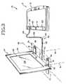
- Figs. 1-3show a notebook computer 10, 10', 10'' according to three alternative embodiments of this invention.
- the notebook computer 10, 10', 10''includes a system unit 12 and a detachable display unit 14, 14', 14''.
- the system unit 12includes a housing 16, a keyboard 18, a motherboard with central processing unit (not shown), a pointing device 20, a clicking device 21, and a mass storage device (not shown).
- the system unit 12also includes any one or more of the following: one or more expansion slots, various I/O ports, and a fax/modem or other peripheral device embodied in a plug-in PC card.
- Each display unit 14, 14', 14''includes a flat panel display 22, a display housing 24 and an integral support.
- the system unit 12 and display unit 14reside on a common or separate surface S.
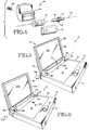
- a planar support 26extends the length of the display housing 24 and is rotatably coupled to the display housing 24.
- two spaced supports 30are rotatably coupled to the display housing 24.
- the planar support 26 and the two spaced supports 30each fold down and/or out from the display housing 24.
- two supports 34are coupled to a bottom edge of the display housing and rotate relative to a plane of the display unit with multiple degrees of freedom.
- a cable 38, fiberoptic 40 or other communication link(e.g., infrared) provides a signal path between the system unit 12 and the detached display unit 14, 14', 14''.
- the support 26includes an extension 42 and a pair of hinges 44.
- the hinges 44are located at the lower edge 52 of the display housing 24.
- the extension 42rotates out and down from the display housing 24 toward the surface S.
- the extension 42serves as a base defining a support plane 50 of sufficient length and width to stabilize the display unit 14 when detached and set up for use.
- the extension 42is formed of molded plastic, and extends the length of the display housing 24 and a width of at least one half the height of the display housing 24.
- the hinges 44are located away from the bottom edge 52, preferably within the area between the top edge 64 and mid-height, inclusive of the display housing 24.
- the extension 42rotates out from the bottom edge 52 defining a leg.
- the support plane 50then is along the length of the leg. In either embodiment the angle between the support plane 50 and a viewing plane defined by the display panel 22 is adjustable.
- the supports 30include a pair of extensions 66 and the respective hinges 44.
- the hinges 44are located at the lower edge 52 of the display housing extension.
- the extensions 66rotate out and down from the display housing 24 toward the surface S.
- the extensions 66define a support plane 50.
- the legs 66are located sufficiently apart and of sufficient length to stabilize the display unit 14 when detached and set up for use.
- the extensions 66are formed of molded plastic, are spread the length of the display housing 24, and have a length at least one half the height of the display housing 24.
- the hinges 44are located away from the bottom edge 52, preferably within the area between the top edge 64 and mid-height, inclusive of the display housing 24.
- the extensions 66rotate out from the bottom edge 52 defining a pair of legs.
- the support plane 50then is along the length of the legs. In either embodiment the angle between the support plane 50 and a viewing plane defined by the display panel 22 is adjustable.
- Each support hinge 44allows for movement of an extension (42/66) in one degree of freedom relative to the display housing 24. There is sufficient resistance to motion in the support hinge 44, however, to maintain a fixed angular relationship between the support plane 50 and the viewing plane under the weight of the display housing 24 and panel 22.
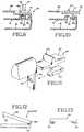
- Fig. 4shows an exploded view of the support hinge 44.
- Each hinge 44includes a plastic tube 70 fitted between a cap 72 and a hinge housing 74.
- a pin 76protrudes from the display housing 24 and mates to the tube 70 to define an axis of rotation 78 for the support 26/30.
- a spring 77abuts the plastic tube 70 at spring end 79. The end 79 is in fixed relationship to the tube 70, moving with the tube 70 (see Figs. 4 and 12). More specifically, the spring provides resistance countering the weight of the display housing 24 and panel 22.
- the pin 76also serves as a connecting link joining the support 26/30 to the display housing 24.
- a screw 80holds the cap 72 and tube
- each support 34includes a planar extension 81 and a coupling mechanism 82.
- the coupling mechanism 82allow movement of an extension 81 in multiple degrees of freedom relative to the display housing 24.
- the coupling mechanismincludes a ball joint.
- the two extensions 81have a length accumulating to the approximate length of the display housing 24.
- the ball joints 82have sufficient frictional resistance to maintain the display housing 24 and panel 22 in a fixed position relative to the extensions 81 under the weight of the housing 24 and panel 22.
- Each extension 81is movable about a first axis 89 which is parallel to the bottom edge 52 of the display housing 24.
- One extension 81also is movable about a second axis 91 orthogonal to the first axis 89.
- the other extension 81is movable about a third axis 93 parallel to the second axis 91 and orthogonal to the first axis 89.
- the axes of rotation 89, 91, 93are variable.
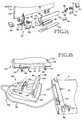
- Figs. 5-8depict the detachment of the display unit 14, 14', 14'' from the system unit 12 according to an embodiment of this invention.
- the display unit 14, 14', 14''while attached to the system unit 12, rotates about an axis 84 between an open position (shown) and a closed position. In the closed position the display panel 22 is flat against the system unit 12 at keyboard 18.
- a latch or other mechanism 69secures the display unit 14 in the closed position (not shown) to prevent the display unit 14 from opening during travel.
- the notebook computers 10, 10', 10''includes locking mechanisms 86/86' for preventing detachment of the display unit 14, 14', 14'' from the system unit 12.
- the locking mechanisms 86, 86'have a locked position and an unlocked position.
- the notebook computer 10, 10', 10''is stored in the closed position with the locking mechanisms 86/86' in the locked position.
- To detach the display unit 14, 14', 14'' the notebook computerfirst is opened rotating the display unit out of the closed position away from the system unit 12 as shown in Fig. 5.
- the locking mechanisms 86/86'are slid from the locked position into the unlocked position as shown in Fig. 6.
- the display unit 14, 14', 14''then is detached from the system unit 12 as shown in Figs. 7 or 8.
- connection between edge connectors 116 and 126 of the display unit and system unit, respectivelyis separated, and the connection between posts 98 of the display unit 14, 14', 14'' and openings 122 in the system unit 12 are separated (best seen in Fig. 8).
- Figs. 9 and 10show one embodiment of the locking mechanism 86.
- Each locking mechanism 86includes a planar portion 87, a hook portion 90 protruding from the planar portion 87, and a ridge 160.
- the planar portion 87fits to an area of a frame 88.
- the locking mechanismslides within the frame 88 by pushing or pulling on the ridge 160 or planar portion 87. In doing so, the hooked portion 90 is moved into or out of engagement.
- Fig. 9shows the locking mechanism 86 in the locked position with the hooked portion 90 engaging a ridge 92 of the keyboard housing 16.
- the locking mechanism 86 and frame 88are part of the display unit (as shown in Figs. 3 and 7).
- the keyboard housing 16When pulling the display unit away from the system unit 12 the keyboard housing 16 abuts the hooked portion 90 preventing detachment. By moving the locking mechanism 86 into the unlocked position the hooked portion 90 moves out of engagement with the keyboard housing ridge 92 as shown in Fig. 10. When pulling the display unit away from the system unit 12 the hooked portion 90 clears the ridge 92 allowing detachment.
- Fig. 11shows an alternative embodiment of the locking mechanism 86'.
- the locking mechanism 86' and frame 88are part of the system unit 12 (as shown in fig. 8).
- the locking mechanism 86'includes the planar portion 87 and ridge 160 of the Fig. 8 mechanism 86.
- a hooked portion 90'also is included.
- the hooked portion 90'hooks an opening 100 in the post 98 of the display unit.
- the hooked portion 90'extends away from the planar portion 87 so as to align with the opening 100.
- the hooked portion 90'engages the post 98 at opening 100.
- the post 98is held within opening 122 by the hooked portion 90' preventing detachment.
- the hooked portion 90'moves out of engagement with the post 98 as shown in Fig. 11.
- the post 98clears the hooked portion 90' allowing detachment.
- the locking mechanismsprovide a visual indication of whether the display unit is locked or unlocked while attached to the system unit.
- the planar portion 87extends beyond the sides of the system unit 12 when in the unlocked position (see Figs. 6-8). When in the locked position the planar portions 87 do not extend beyond such edges. Thus, the protruding planar portions 87 provide a visual indication of the locked and unlocked positions.
- the position of the ridge 160lines up to one marker for the locked position and another marker for the unlocked position.
- the planar portion 87has a portion of differing color from the rest of the locking mechanism. When in the locked position such differing color is hidden beneath frame 88. When unlocked such differing color is exposed within the frame 88 perceivable to a user.
- the locking mechanism and ridge 160protrude to one height when in the locked position and another height when in the unlocked position.
- the hooked portion 90 of the locking mechanism 86slides along a shelf 99 of the keyboard housing 16. When slid into the locked position the hooked portion 90 slides off the shelf 99 allowing the locking mechanism 86 to assume a first height relative to the system unit 12. While in the unlocked position the hooked portion 90 is on the shelf causing the locking mechanism 86 to assume a second height relative to the system unit. The second height is higher than the first height. While at the second height the ridge 160 of the locking mechanism 86 prevents the display unit from folding completely flush to the system unit.
- Fig. 13shows locking mechanisms 86 in the locked position relative to the display unit 24. In the locked positions, the ridge 160 is inward from the display screen border where there is sufficient clearance for the display unit to achieve the closed position without being blocked by the locking mechanisms 86.
- the locking mechanisms 86are part of the extensions 81 of the respective supports 34.
- the frame 88is formed in two parts and is embodied by the extensions 81. While attached to the system unit 12, the extensions 81 of the supports 34 extend in a common line and reside in a common plane. Once the display unit 14'' is detached it is put into use by rotating the extensions 81 out of the common line to define separate supports 34 as shown in Fig. 3. The supports are applied to a surface S bringing them into a common support plane 50. The display panel 22 which defines a viewing plane 104 then is oriented at a desired angle relative to the support plane 50. Such angle is adjustable.
- the extensions 81have rotational components about the first axis 89 (see Fig. 3).
- one extensionalso has a rotational component about a second axis 91, while the other extension has a rotational component about the third axis 93.
- the locking mechanisms 86'prevent the display unit from closing when in the unlocked position in the same manner as the locking mechanisms 86 (as per Figs. 12 and 13).
- Each display unit 14, 14', 14''also includes a display hinge 110 for rotating the display unit relative to the system unit while attached to the system unit 12.
- Fig. 14shows an exploded view of the display housing hinge 110.
- the display hinge 110includes a first elongated member 112 and face plate 114.
- a pair of tubes 115 and an electrical edge connector 116are positioned within the elongated member 112.
- the edge connector 116protrudes through the face plate 114.
- the elongated member 112, face plate 114 and edge connector 116remain in fixed orientation relative to the system unit 12 while attached.
- An indentation 113occurs along the length of the elongated member 112. Referring to Figs. 1, 2 and 14 the display unit 24 rotates relative to the hinge 110 into the indentation 113.
- the indentation 113serves to extend the display unit angular position range.
- the display unit 24is able to be rotated further backward into the indentation 113.
- the display hinge 110also include housings 118 integral to the display housing 24.
- the housings 118are spaced apart along the bottom edge 52 of the display housing 24 by a length equal to the length of the elongated member 112.
- Within each housing 118are two pins 76, 83 and two springs 77, 85.
- a cap 120covers the pins and springs within the housing 118.
- the pins 76extend to engage the tubes 70 of the support hinges 44.
- the pins 83extend to engage the tubes 115.
- the frame 88 supporting the locking mechanisms 86are fixed relative to the elongated member 112 and move with the elongated member 112.
- One or more plug connectionshold the display unit to the system unit 12 while attached.
- two posts 98protrude from the face plate 114 of the display hinge 110. These posts 98 mate to openings 122 in the system unit 12.
- a pin 83is hollow to received a flexible circuit 95 or cable electrically linking the edge connector 116 to the display panel 22.
- the flexible circuit 95extends through the pin 83 into the housing 118 up into the display housing 24.
- the edge connector 116mates to an edge connector 126 at the system unit 12 when the display unit is attached to the system unit 12 to provide electrical communication between the display unit 14, 14', 14'' and the system unit 12. While detached, a signal communication link between the display unit 14, 14', 14'' and system unit 12 is established via a cable 38.
- the cable 38couples to the edge connector 116 with an edge connector 128 and to edge connector 128 with an edge connector 130.
- a cableextends from the system unit 12 to the display unit 14, 14', 14'' while the display unit is detached.
- a fiberoptic connection 40is established.
- Such connection 40includes one or more fiberoptics 132 and flexible cable portions 134.
- the fiberoptics 132extend from the system unit 12 to the display unit 14, 14', 14'' (see Fig. 3).
- a permanent or detachable connectionis established at !he display hinge 110 in place of the edge connector 116.
- the fiber optics 132are held by clips 113 within a groove 111 of the system unit while the display is attached to the system unit.
- the fiber optic connectiondefines the signal path between the display unit 14, 14', 14'' and the system unit 12 regardless of whether the display unit is attached or detached.
- a cableextends from the system unit 12 an infrared communication link is established between the display unit and system unit 12.
- the cable 38is removed.
- the supports 34then are rotated back into a common line parallel to the lower edge 52 of the display housing 24.
- the supports 34also are oriented into a common plane. Further, the supports are positioned with the locking mechanisms 86 pointing out toward the side edges of the display housing 24.
- the posts 98 of the display unit 14''then are plugged back into the openings 122 of the system unit.
- the edge connector 116is mated to the edge connector 126.
- the fiber optics 132are folded as the display unit is moved toward the system unit.
- the supports 34are oriented in the common line and common plane as described above.
- the supports 34 and fiberoptics 132then are inserted into the recess 111.
- the fiberoptics 132are snapped into clips 113 which hold the fiberoptics 132 in place.
- the fiberoptic signal pathis removable and the display reconnected without fiberoptics.
- the locking mechanisms 86then are moved into the locked position.
- the display unit 14''is now attached.
- the computer 10''can then be stowed or operated with the attached display.
- the cable 38is removed and the extension 42/66 are folded to the display unit.
- the display unit 14, 14'then is plugged into the system unit 12.
- the edge connector 116is mated to the edge connector 126.
- the posts 98are mated to the openings 112.
- the fiberoptics 132are stowed as described above for display unit 14''.
- the display unit 14, 14'is now attached and operational. It is preferred that the display unit next be locked to the system unit. This is achieved by moving the locking mechanisms 86/86' to the locked position. Once locked, the display unit is closed to the system unit. As described above, the computer cannot be closed with the display unit latched to the system unit via latch 69 unless the locking mechanisms 86/86' are moved to the locked position.
- Figs. 15 and 16show a separate stand 136 which is not integral to a notebook computer.
- the notebook computerincludes a system unit 12 as previously described, along with a detachable display unit 140.
- the display unit 140is embodied by a display unit 14, 14', 14'' embodiment as previously described. In some embodiments the display unit 140 does not include the integral support 26/30/34.
- the separate stand 136includes a base 142, an arm 144 and a connection interface 146.
- the standalso includes a cable 38 having edge connectors 128, 130 at opposing ends.
- the display unit 140plugs into the connection interface 146 via posts 98.
- the posts 98are received into respective openings 148 at the connection interface 146.
- the edge connector 116 of the display unit 140mates to the edge connector 128 of the stand 136.
- the connection interface 146defines an elongated surface 150.
- the display unit 140is rotatable relative to the connection interface 46 via the display hinge 110.
- the display hinge 110defines a pivot axis 152 (see Fig. 16) allowing a user to define the orientation of the viewing plane of the display unit 140.
- the arm 144is rotatable about an axis 156 relative to the stand base 142.
- the armis movable between a first position in which the connection interface 46 is closest to the base 142 to a second position at which the connection interface 146 is removed from the base 142.
- Rotation of the arm 144adjusts the height of the display unit 140.
- the axis 156is defined by a hinge 158.
- the hinge 158includes like components as the display hinge components 83, 85, and 115.
- the hinge 158 springs(e.g., 85) provide sufficient resistance to maintain the arm at a fixed position under the weight of the display unit 140.
- the baseis of varying shape and size.
- the base 142is of sufficient size to prevent the stand 136 from tipping under the weight of the display stand 140.
- One advantage of the inventionis that a user can independently define positions for a notebook computer keyboard and display so as to improve ergonomic comfort, without compromising computer transportability.
- An advantage regarding the separate stand embodiment,is that the user can adjust the viewing height of the detached display.
Landscapes
- Engineering & Computer Science (AREA)
- Theoretical Computer Science (AREA)
- Computer Hardware Design (AREA)
- General Engineering & Computer Science (AREA)
- Physics & Mathematics (AREA)
- Human Computer Interaction (AREA)
- General Physics & Mathematics (AREA)
- Mathematical Physics (AREA)
- Devices For Indicating Variable Information By Combining Individual Elements (AREA)
- Casings For Electric Apparatus (AREA)
Abstract
Description
Claims (5)
- A portable computer (10), comprising:a system unit (12) having a keyboard (18);a flat panel display unit (14) removably attached to the system unit, the display unitfolding relative to the system unit between an open position for viewing a display panel (22) of thedisplay unit and a closed position at which the display panel is held to the system unit, wherein thedisplay unit comprises a display housing (24), the display panel (22) and a support (26/30/34), theflat panel display mounted to the display housing and defining a viewing plane (104), the supporthinged to the display housing and defining a support plane (50); and wherein the display unit restsupon the support when detached from the system unit, the display housing rotating relative to thesupport to define an angle between the viewing plane and the support plane; andmeans (86) for locking the display unit to the system unit; wherein the display unitis undetachable from the system unit while locked; and wherein the display unit is rotatable relativeto the system unit while locked; andmeans (160) for preventing the display unit from achieving a closed position whenthe display unit is unlocked relative to the system unit.
- The portable computer of claim 1, further comprising means (86) forindicating whether the display unit is locked or unlocked when attached to the system unit.
- The portable computer of claim 2, in which the indicating means comprisesthe preventing means.
- The portable computer of claim 1, in which the support (30/34) comprises afirst support (66/81) and a second support (66/81), the first support and second support beingindependently rotatable relative to the viewing plane (104), the first support and second supportdefining the support plane (50) when supporting the display unit, the first support and secondsupport rotatable about a common first axis (89) to define the support plane, the first supportrotatable about a second axis (91) for rotating within the support plane, the second supportrotatable about a third axis (93) for rotating within the support plane.
- A display stand (136) for supporting a detachable display (140) of aportable computer (10), the portable computer having a system unit (12) and the detachable displayunit (140), the display unit foldable relative to the system unit between an open position forviewing a display panel (22) of the display unit and a closed position at which the display panel isheld to the system unit, the stand comprising:a base (142) upon which the display stand rests, the base defining a support plane;means (146) for receiving the display unit when detached from the system unit;an arm (144) located between the base and receiving means, the arm rotatablerelative to the support plane to define an adjustable height for viewing the display unit; andmeans (38) for maintaining signal communication between the display unit and thesystem unit.
Applications Claiming Priority (2)
| Application Number | Priority Date | Filing Date | Title |
|---|---|---|---|
| US725527 | 1996-10-03 | ||
| US08/725,527US5805415A (en) | 1996-10-03 | 1996-10-03 | Detachable flat panel computer display and support |
Publications (3)
| Publication Number | Publication Date |
|---|---|
| EP0834792A2true EP0834792A2 (en) | 1998-04-08 |
| EP0834792A3 EP0834792A3 (en) | 1998-06-24 |
| EP0834792B1 EP0834792B1 (en) | 2001-12-05 |
Family
ID=24914905
Family Applications (1)
| Application Number | Title | Priority Date | Filing Date |
|---|---|---|---|
| EP97307090AExpired - LifetimeEP0834792B1 (en) | 1996-10-03 | 1997-09-12 | Detachable flat panel computer display and support |
Country Status (8)
| Country | Link |
|---|---|
| US (1) | US5805415A (en) |
| EP (1) | EP0834792B1 (en) |
| JP (1) | JP3859320B2 (en) |
| KR (1) | KR100491933B1 (en) |
| CN (2) | CN1252554C (en) |
| DE (1) | DE69708821T2 (en) |
| SG (1) | SG67972A1 (en) |
| TW (1) | TW444155B (en) |
Cited By (18)
| Publication number | Priority date | Publication date | Assignee | Title |
|---|---|---|---|---|
| FR2782400A1 (en)* | 1998-08-03 | 2000-02-18 | Source Dev | Portable computer having a flat screen that can be packed away in a briefcase has two operation modes, one where the screen flips down from its briefcase compartment and the other where it is used as a stand-alone flat screen |
| EP1031911A1 (en)* | 1999-02-23 | 2000-08-30 | Sharp Kabushiki Kaisha | Data processing apparatus with detachable keyboard |
| GB2352534A (en)* | 1999-03-09 | 2001-01-31 | Charles Richard Webster | Laptop computer with removable screen |
| EP0965905A3 (en)* | 1998-06-15 | 2003-05-14 | Samsung Electronics Co., Ltd. | Assembly structure of display of electronic appliance |
| EP1085397A3 (en)* | 1999-09-14 | 2003-08-27 | SAMSUNG ELECTRONICS Co. Ltd. | Display connection structure of electronic appliance |
| US6628506B2 (en) | 2001-07-24 | 2003-09-30 | Hewlett-Packard Development Company, L.P. | Multifunctional foldable computer |
| WO2003025724A3 (en)* | 2001-09-14 | 2003-12-31 | Nicholas J Pappas | Multipurpose computer display system |
| DE10101108B4 (en)* | 2000-04-14 | 2004-05-06 | Acer Inc. | Flat panel display unit with an attachable computer and information device |
| KR100462590B1 (en)* | 1998-06-15 | 2004-12-20 | 삼성전자주식회사 | Structure for coupling display of electronic device |
| US6873521B2 (en) | 2001-07-24 | 2005-03-29 | Hewlett-Packard Development Company, L.P. | Multiple environment foldable computer |
| GB2381990B (en)* | 2001-11-05 | 2005-09-21 | Nec Corp | Foldable electronic device |
| GB2418270A (en)* | 2004-09-15 | 2006-03-22 | Tatung Co Ltd | Detachable wireless display system |
| EP1461947A4 (en)* | 2001-12-31 | 2008-07-02 | Toshio Hayakawa | Multimedia system incorporating portable computer, television, and cellular phone |
| EP2111716A4 (en)* | 2007-11-20 | 2011-02-23 | Lg Electronics Inc | SUPPORT APPARATUS FOR A DISPLAY DEVICE |
| US7981663B2 (en) | 2006-01-13 | 2011-07-19 | Roche Diagnostics Operations, Inc. | Group of reagent carriers that is combined to form a composite |
| WO2015088520A3 (en)* | 2013-12-11 | 2015-09-17 | Hewlett-Packard Development Company, L.P. | Retractable structure for a computing device |
| US9342111B2 (en) | 2013-11-29 | 2016-05-17 | Wistron Corporation | Electronic device having supporting mechanism |
| CN110073309A (en)* | 2016-10-14 | 2019-07-30 | 卢卡·杰拉尔迪 | Modular computing system |
Families Citing this family (77)
| Publication number | Priority date | Publication date | Assignee | Title |
|---|---|---|---|---|
| KR200239035Y1 (en)* | 1997-10-07 | 2001-11-22 | 윤종용 | Handheld Computer with Detachable Keyboard and Thin Film Display |
| US6556435B1 (en) | 1997-10-31 | 2003-04-29 | Hewlett-Packard Company | Adjustable height docking station and computing device for use therewith |
| US6982702B1 (en)* | 1998-06-12 | 2006-01-03 | Hewlett-Packard Development Company, L.P. | Portable computer system |
| US6118663A (en)* | 1998-06-12 | 2000-09-12 | Fan; Yu-Han | Multi-configuration modular computer |
| US6816145B1 (en)* | 1998-07-22 | 2004-11-09 | Silicon Graphics, Inc. | Large area wide aspect ratio flat panel monitor having high resolution for high information content display |
| US6263391B1 (en)* | 1998-09-24 | 2001-07-17 | Adaptec, Inc. | Modular bus bridge |
| US6028764A (en)* | 1998-09-28 | 2000-02-22 | Intel Corporation | Portable computer with separable screen |
| WO2000028510A2 (en)* | 1998-11-12 | 2000-05-18 | Thomas Cies | Z-configuration structure for computers, scanners, and communications and video devices |
| JP3540187B2 (en)* | 1999-02-25 | 2004-07-07 | シャープ株式会社 | Display device |
| US6198625B1 (en)* | 1999-06-03 | 2001-03-06 | Micron Electronics, Inc. | Hinge assembly for a portable computer |
| DE29910884U1 (en)* | 1999-06-28 | 1999-09-16 | First International Computer Inc., Taipeh/T'ai-Pei | Notebook computer with a connection structure for signal lines of a liquid crystal display device |
| USD436760S1 (en) | 1999-07-08 | 2001-01-30 | Rocky Lee Dow | Ergonomic notebook stand |
| US6223393B1 (en) | 1999-07-09 | 2001-05-01 | International Business Machines Corporation | Redundant hinge element for a notebook computer |
| US6233138B1 (en) | 1999-07-16 | 2001-05-15 | Evergreen Innovations, L.L.C. | Telescoping pivot hinge for computer display |
| JP2001051752A (en) | 1999-08-10 | 2001-02-23 | Nec Corp | Portable personal computer loading camera |
| US6433791B2 (en)* | 1999-08-10 | 2002-08-13 | Smar Research Corporation | Displaceable display arrangement |
| US6266241B1 (en) | 1999-09-29 | 2001-07-24 | Hewlett-Packard Company | Notebook computer with ergonomic stand |
| US20050035950A1 (en)* | 1999-10-19 | 2005-02-17 | Ted Daniels | Portable input device for computer |
| US6437973B1 (en)* | 2000-04-18 | 2002-08-20 | Hewlett-Packard Company | Modular mechanism for movable display |
| KR100636120B1 (en)* | 2000-04-29 | 2006-10-18 | 삼성전자주식회사 | Display coupling structure of electronic products |
| KR100611966B1 (en)* | 2000-05-18 | 2006-08-11 | 삼성전자주식회사 | Display coupling structure of electronic products |
| US6381128B1 (en) | 2000-07-17 | 2002-04-30 | Russel G. Kramer | Ergonomic portable computer |
| US6919864B1 (en)* | 2000-07-27 | 2005-07-19 | Avaya Technology Corp. | Display monitor |
| US6512670B1 (en)* | 2000-10-05 | 2003-01-28 | International Business Machines Corporation | Detachable displays or portable devices |
| USD451306S1 (en) | 2000-10-20 | 2001-12-04 | Rock Solid Solutions | Portable computer stand |
| US20020140690A1 (en)* | 2001-03-30 | 2002-10-03 | Gamsaragan Edward V. | Computer with communicating separable computing display subsystem |
| JP4075335B2 (en)* | 2001-04-11 | 2008-04-16 | 松下電器産業株式会社 | Electronics |
| KR100427191B1 (en)* | 2001-07-05 | 2004-04-17 | (주)아이디에스테크놀로지 | LCD display apparatus |
| US6963487B2 (en)* | 2001-10-25 | 2005-11-08 | Hewlett-Packard Development Company, L.P. | Pedestal computer docking station |
| US20040155861A1 (en)* | 2002-05-30 | 2004-08-12 | Jackson Iii Robert P. | Portable display monitor |
| US7046213B2 (en)* | 2002-06-05 | 2006-05-16 | Ibm | Apparatus and method for direct manipulation of electronic information |
| JP4122183B2 (en)* | 2002-06-28 | 2008-07-23 | クラリオン株式会社 | Display unit control device |
| US20040048674A1 (en)* | 2002-09-09 | 2004-03-11 | Intec, Inc. | Video display unit for video game console |
| TW569086B (en)* | 2002-09-27 | 2004-01-01 | Quanta Comp Inc | Combinational device of notebook computer |
| TW594126B (en)* | 2002-10-03 | 2004-06-21 | Wistron Corp | Liquid crystal display panel and notebook computer having the same |
| US6987666B2 (en)* | 2003-03-26 | 2006-01-17 | Dell Products L.P. | Flat panel monitor stand |
| TWM250194U (en)* | 2003-04-16 | 2004-11-11 | Aopen Inc | Cover applied to a computer with a display |
| US20040228077A1 (en)* | 2003-04-16 | 2004-11-18 | Hall Rick S. | Height adjustable computer monitor and document holder |
| KR100534125B1 (en)* | 2003-12-10 | 2005-12-08 | 삼성전자주식회사 | Portable computer |
| US6989987B1 (en)* | 2004-02-06 | 2006-01-24 | Marqueta Wilson | Reconfigurable computer monitor |
| US20050202879A1 (en)* | 2004-03-09 | 2005-09-15 | Intec, Inc. | Detachable display for video console |
| WO2005119404A1 (en)* | 2004-06-01 | 2005-12-15 | Beech Technology Incorporated | Portable, folding and separable multi-display computing system |
| US7471506B2 (en)* | 2004-09-22 | 2008-12-30 | Hewlett-Packard Development Company, L.P. | Method and system of a portable computer with a detachable display |
| US7540806B2 (en)* | 2005-01-10 | 2009-06-02 | Wms Gaming Inc. | Releasable display mounting system and method |
| TWM275445U (en)* | 2005-01-31 | 2005-09-11 | Inventec Multimedia & Telecom | Multimedia display device having detachable display panel |
| KR100730717B1 (en)* | 2005-05-10 | 2007-06-21 | 삼성전자주식회사 | Portable computer with detachable display |
| KR100676820B1 (en)* | 2005-05-23 | 2007-02-01 | 삼성전자주식회사 | Portable computer with detachable display |
| US8794579B2 (en) | 2005-06-03 | 2014-08-05 | Steelcase, Inc. | Support arm assembly |
| KR100607679B1 (en)* | 2005-07-07 | 2006-08-01 | 삼성전자주식회사 | Portable computer |
| KR100653072B1 (en)* | 2005-08-23 | 2006-12-01 | 삼성전자주식회사 | Display device |
| TWI275305B (en)* | 2005-09-13 | 2007-03-01 | Benq Corp | Flat panel display device |
| US7215538B1 (en)* | 2005-10-18 | 2007-05-08 | Shaofen Chen | Portable computer with multi-sectioned arms to support display position adjustment and multiple configurations |
| US7974084B2 (en)* | 2005-10-18 | 2011-07-05 | Computer Ergotech, Llc | Multi-sectioned arms for portable electronic devices |
| US8089750B2 (en)* | 2005-10-18 | 2012-01-03 | Computer Ergotech, Llc | Multi-sectioned arms for portable electronic devices |
| US7656652B2 (en)* | 2005-11-09 | 2010-02-02 | George Moser | Portable computer with reconfigurable display |
| KR100849563B1 (en)* | 2006-06-13 | 2008-07-31 | 엘지전자 주식회사 | Supporting apparatus for display |
| US20080165479A1 (en)* | 2007-01-05 | 2008-07-10 | Juen-Tien Peng | Display Screen Used in Game Machine |
| JP2009069523A (en)* | 2007-09-13 | 2009-04-02 | Sony Corp | Display device |
| US20090122019A1 (en)* | 2007-11-12 | 2009-05-14 | Dell Products L.P. | Display For Information Handling System |
| GB201009952D0 (en)* | 2010-05-11 | 2010-07-21 | Hu Do Ltd | Hinge development |
| US9316346B2 (en) | 2010-06-09 | 2016-04-19 | Colebrook Bosson Saunders (Products) Limited | Support system |
| US9074721B2 (en) | 2010-06-09 | 2015-07-07 | Alex Lau | Support system |
| US8956061B2 (en) | 2010-07-07 | 2015-02-17 | Cervantes Mobile | Compact keyboard and cradle |
| USD684982S1 (en) | 2010-08-11 | 2013-06-25 | Colebrook Bosson Saunders (Products) Limited | Display support with indicator window |
| TWI476738B (en) | 2010-09-07 | 2015-03-11 | Ind Tech Res Inst | Flexible display panel and assembly method thereof |
| US9001504B2 (en) | 2010-12-28 | 2015-04-07 | Google Inc. | Moveable display portion of a computing device |
| US9207711B2 (en) | 2011-07-22 | 2015-12-08 | Hewlett-Packard Development Company, L.P. | Display stand with cable routing underpass |
| TWI489249B (en)* | 2012-08-08 | 2015-06-21 | Wistron Corp | Portable electronic device and housing structure |
| US9477262B2 (en) | 2012-09-10 | 2016-10-25 | Google Inc. | Moveable display portion of a computing device including a clutch mechanism |
| USD700600S1 (en) | 2012-09-10 | 2014-03-04 | Google Inc. | Display and base portion of a computing device |
| US9494976B2 (en)* | 2012-09-11 | 2016-11-15 | Logitech Europe S.A. | Protective cover for a tablet computer |
| US9766661B2 (en) | 2013-07-30 | 2017-09-19 | Intel Corporation | Stacking detachable tablet |
| US9354670B2 (en)* | 2013-08-26 | 2016-05-31 | General Electric Company | Apparatus and method for pivot attachment |
| US9690332B2 (en)* | 2013-10-09 | 2017-06-27 | Kabushiki Kaisha Toshiba | Electronic device, combining device, and detaching method |
| US9740240B1 (en) | 2016-03-21 | 2017-08-22 | Google Inc. | Base with rotating mount that increases friction of rotation when portable computing device is placed onto mount |
| CN110069099A (en)* | 2019-03-28 | 2019-07-30 | 山东超越数控电子股份有限公司 | A kind of hinge connector and computer |
| CN114253350B (en)* | 2020-09-21 | 2023-12-08 | 华为技术有限公司 | Electronic equipment |
Family Cites Families (16)
| Publication number | Priority date | Publication date | Assignee | Title |
|---|---|---|---|---|
| AU594385B2 (en)* | 1986-03-20 | 1990-03-08 | Wang Laboratories, Inc. | Display attachment apparatus |
| JPH061422B2 (en)* | 1988-09-22 | 1994-01-05 | インターナショナル・ビジネス・マシーンズ・コーポレーション | Electronics with keyboard |
| US5144290A (en)* | 1988-10-31 | 1992-09-01 | Kabushiki Kaisha Toshiba | Display unit attachment device |
| US4978949A (en)* | 1989-03-06 | 1990-12-18 | Dynabook Technologies Corporation | Locking mechanism and support legs for removable display assembly |
| US5196993A (en)* | 1989-03-06 | 1993-03-23 | Unisys Corp. | Removable stand alone display for laptop computer |
| US5100098A (en)* | 1989-06-12 | 1992-03-31 | Grid Systems Corporation | Stand and handle for hand held computer |
| US4964018A (en)* | 1989-10-05 | 1990-10-16 | Tektronix, Inc. | Multi-purpose display module system for an electronic instrument |
| US5128829A (en)* | 1991-01-11 | 1992-07-07 | Health Innovations, Inc. | Hinge and stand for hand-held computer unit |
| CN2103831U (en)* | 1991-07-12 | 1992-05-06 | 马希光 | separate portable computer |
| US5247285A (en)* | 1992-03-06 | 1993-09-21 | Everex Systems, Inc. | Standup portable personal computer with detachable wireless keyboard and adjustable display |
| CA2110189C (en)* | 1992-11-30 | 1999-06-15 | Kaori Honjo | A notebook type information processing apparatus having input function with pen |
| USD358374S (en) | 1992-12-14 | 1995-05-16 | International Business Machines Corporation | Portable personal computer |
| US5375076A (en)* | 1993-09-10 | 1994-12-20 | Compaq Computer Corporation | Combined notepad and notebook computer |
| KR960006917Y1 (en)* | 1993-11-29 | 1996-08-12 | 삼성전자 주식회사 | Hinge lock on computer |
| WO1995024007A1 (en)* | 1994-03-02 | 1995-09-08 | Lane Jeffrey P | Modular, reconfigurable devices |
| US5582373A (en)* | 1994-10-24 | 1996-12-10 | Hewlett-Packard Company | Support structure with fold-away arms |
- 1996
- 1996-10-03USUS08/725,527patent/US5805415A/ennot_activeExpired - Lifetime
- 1997
- 1997-03-04SGSG1997000643Apatent/SG67972A1/enunknown
- 1997-04-29TWTW086105627Apatent/TW444155B/ennot_activeIP Right Cessation
- 1997-09-12DEDE69708821Tpatent/DE69708821T2/ennot_activeExpired - Lifetime
- 1997-09-12EPEP97307090Apatent/EP0834792B1/ennot_activeExpired - Lifetime
- 1997-09-22JPJP25716797Apatent/JP3859320B2/ennot_activeExpired - Lifetime
- 1997-09-29CNCNB031365140Apatent/CN1252554C/ennot_activeExpired - Fee Related
- 1997-09-29CNCN97119215Apatent/CN1114856C/ennot_activeExpired - Fee Related
- 1997-10-01KRKR1019970050736Apatent/KR100491933B1/ennot_activeExpired - Fee Related
Cited By (25)
| Publication number | Priority date | Publication date | Assignee | Title |
|---|---|---|---|---|
| EP0965905A3 (en)* | 1998-06-15 | 2003-05-14 | Samsung Electronics Co., Ltd. | Assembly structure of display of electronic appliance |
| KR100462590B1 (en)* | 1998-06-15 | 2004-12-20 | 삼성전자주식회사 | Structure for coupling display of electronic device |
| EP1418488A1 (en)* | 1998-06-15 | 2004-05-12 | Samsung Electronics Co., Ltd. | Assembly structure of display of electronic appliance |
| FR2782400A1 (en)* | 1998-08-03 | 2000-02-18 | Source Dev | Portable computer having a flat screen that can be packed away in a briefcase has two operation modes, one where the screen flips down from its briefcase compartment and the other where it is used as a stand-alone flat screen |
| EP1031911A1 (en)* | 1999-02-23 | 2000-08-30 | Sharp Kabushiki Kaisha | Data processing apparatus with detachable keyboard |
| US6593859B1 (en) | 1999-02-23 | 2003-07-15 | Sharp Kabushiki Kaisha | Data processing apparatus |
| GB2352534A (en)* | 1999-03-09 | 2001-01-31 | Charles Richard Webster | Laptop computer with removable screen |
| EP1085397A3 (en)* | 1999-09-14 | 2003-08-27 | SAMSUNG ELECTRONICS Co. Ltd. | Display connection structure of electronic appliance |
| DE10101108B4 (en)* | 2000-04-14 | 2004-05-06 | Acer Inc. | Flat panel display unit with an attachable computer and information device |
| US6873521B2 (en) | 2001-07-24 | 2005-03-29 | Hewlett-Packard Development Company, L.P. | Multiple environment foldable computer |
| US6654234B2 (en)* | 2001-07-24 | 2003-11-25 | Hewlett-Packard Development Company, L.P. | Multifunctional foldable computer |
| US6628506B2 (en) | 2001-07-24 | 2003-09-30 | Hewlett-Packard Development Company, L.P. | Multifunctional foldable computer |
| US7129931B2 (en) | 2001-09-14 | 2006-10-31 | Pappas Nicholas J | Multipurpose computer display system |
| WO2003025724A3 (en)* | 2001-09-14 | 2003-12-31 | Nicholas J Pappas | Multipurpose computer display system |
| GB2381990B (en)* | 2001-11-05 | 2005-09-21 | Nec Corp | Foldable electronic device |
| EP1461947A4 (en)* | 2001-12-31 | 2008-07-02 | Toshio Hayakawa | Multimedia system incorporating portable computer, television, and cellular phone |
| GB2418270A (en)* | 2004-09-15 | 2006-03-22 | Tatung Co Ltd | Detachable wireless display system |
| US7981663B2 (en) | 2006-01-13 | 2011-07-19 | Roche Diagnostics Operations, Inc. | Group of reagent carriers that is combined to form a composite |
| EP2111716A4 (en)* | 2007-11-20 | 2011-02-23 | Lg Electronics Inc | SUPPORT APPARATUS FOR A DISPLAY DEVICE |
| KR101424269B1 (en)* | 2007-11-20 | 2014-07-31 | 엘지전자 주식회사 | Mounting apparatus for flat display device |
| US9342111B2 (en) | 2013-11-29 | 2016-05-17 | Wistron Corporation | Electronic device having supporting mechanism |
| WO2015088520A3 (en)* | 2013-12-11 | 2015-09-17 | Hewlett-Packard Development Company, L.P. | Retractable structure for a computing device |
| US11360522B2 (en) | 2013-12-11 | 2022-06-14 | Hewlett-Packard Development Comany, L.P. | Retractable structure for a computing device |
| CN110073309A (en)* | 2016-10-14 | 2019-07-30 | 卢卡·杰拉尔迪 | Modular computing system |
| CN110073309B (en)* | 2016-10-14 | 2024-02-06 | 卢卡·杰拉尔迪 | modular computing system |
Also Published As
| Publication number | Publication date |
|---|---|
| US5805415A (en) | 1998-09-08 |
| CN1515992A (en) | 2004-07-28 |
| CN1114856C (en) | 2003-07-16 |
| SG67972A1 (en) | 1999-10-19 |
| KR19980032456A (en) | 1998-07-25 |
| TW444155B (en) | 2001-07-01 |
| DE69708821D1 (en) | 2002-01-17 |
| EP0834792A3 (en) | 1998-06-24 |
| EP0834792B1 (en) | 2001-12-05 |
| CN1178939A (en) | 1998-04-15 |
| DE69708821T2 (en) | 2002-04-11 |
| CN1252554C (en) | 2006-04-19 |
| KR100491933B1 (en) | 2005-08-05 |
| JP3859320B2 (en) | 2006-12-20 |
| JPH10124186A (en) | 1998-05-15 |
Similar Documents
| Publication | Publication Date | Title |
|---|---|---|
| US5805415A (en) | Detachable flat panel computer display and support | |
| US7277275B2 (en) | Portable computer having adjustable display | |
| KR100652783B1 (en) | Apparatus for automatically adjusting an angle of image unit for information processing equipment | |
| US5899421A (en) | Stand for a portable computer | |
| US6437973B1 (en) | Modular mechanism for movable display | |
| US7283355B2 (en) | Portable computer | |
| EP1628191B1 (en) | Portable Computer | |
| US7221562B2 (en) | Portable computer | |
| US6302612B1 (en) | Pivotally extensible display device | |
| US5915661A (en) | Collapsible desk stand for portable computer | |
| US5822185A (en) | Ergonomic docking station for a portable computer | |
| CA2392105C (en) | Computer display screen system and adjustable screen mount, and swinging screens therefor | |
| US20090167634A1 (en) | Systems having detachable twin display monitors | |
| WO2000039493A1 (en) | Computer display screen system and adjustable screen mount, and swinging screens therefor | |
| US20050270731A1 (en) | Computer docking system | |
| KR100690908B1 (en) | Image unit automatic adjustment device of information processing equipment | |
| KR0114809Y1 (en) | Portable computer system and combination structure of output apparatus |
Legal Events
| Date | Code | Title | Description |
|---|---|---|---|
| PUAI | Public reference made under article 153(3) epc to a published international application that has entered the european phase | Free format text:ORIGINAL CODE: 0009012 | |
| AK | Designated contracting states | Kind code of ref document:A2 Designated state(s):DE FR GB | |
| AX | Request for extension of the european patent | Free format text:AL;LT;LV;RO;SI | |
| PUAL | Search report despatched | Free format text:ORIGINAL CODE: 0009013 | |
| AK | Designated contracting states | Kind code of ref document:A3 Designated state(s):AT BE CH DE DK ES FI FR GB GR IE IT LI LU MC NL PT SE | |
| AX | Request for extension of the european patent | Free format text:AL;LT;LV;RO;SI | |
| 17P | Request for examination filed | Effective date:19980812 | |
| AKX | Designation fees paid | Free format text:DE FR GB | |
| RBV | Designated contracting states (corrected) | Designated state(s):DE FR GB | |
| 17Q | First examination report despatched | Effective date:20000922 | |
| GRAG | Despatch of communication of intention to grant | Free format text:ORIGINAL CODE: EPIDOS AGRA | |
| RAP1 | Party data changed (applicant data changed or rights of an application transferred) | Owner name:HEWLETT-PACKARD COMPANY, A DELAWARE CORPORATION | |
| GRAG | Despatch of communication of intention to grant | Free format text:ORIGINAL CODE: EPIDOS AGRA | |
| GRAH | Despatch of communication of intention to grant a patent | Free format text:ORIGINAL CODE: EPIDOS IGRA | |
| GRAG | Despatch of communication of intention to grant | Free format text:ORIGINAL CODE: EPIDOS AGRA | |
| GRAH | Despatch of communication of intention to grant a patent | Free format text:ORIGINAL CODE: EPIDOS IGRA | |
| GRAH | Despatch of communication of intention to grant a patent | Free format text:ORIGINAL CODE: EPIDOS IGRA | |
| GRAA | (expected) grant | Free format text:ORIGINAL CODE: 0009210 | |
| AK | Designated contracting states | Kind code of ref document:B1 Designated state(s):DE FR GB | |
| REG | Reference to a national code | Ref country code:GB Ref legal event code:IF02 | |
| REF | Corresponds to: | Ref document number:69708821 Country of ref document:DE Date of ref document:20020117 | |
| PLBE | No opposition filed within time limit | Free format text:ORIGINAL CODE: 0009261 | |
| STAA | Information on the status of an ep patent application or granted ep patent | Free format text:STATUS: NO OPPOSITION FILED WITHIN TIME LIMIT | |
| 26N | No opposition filed | ||
| PGFP | Annual fee paid to national office [announced via postgrant information from national office to epo] | Ref country code:DE Payment date:20100929 Year of fee payment:14 | |
| PGFP | Annual fee paid to national office [announced via postgrant information from national office to epo] | Ref country code:GB Payment date:20110926 Year of fee payment:15 Ref country code:FR Payment date:20111005 Year of fee payment:15 | |
| REG | Reference to a national code | Ref country code:GB Ref legal event code:732E Free format text:REGISTERED BETWEEN 20120329 AND 20120404 | |
| GBPC | Gb: european patent ceased through non-payment of renewal fee | Effective date:20120912 | |
| REG | Reference to a national code | Ref country code:FR Ref legal event code:ST Effective date:20130531 | |
| PG25 | Lapsed in a contracting state [announced via postgrant information from national office to epo] | Ref country code:DE Free format text:LAPSE BECAUSE OF NON-PAYMENT OF DUE FEES Effective date:20130403 Ref country code:GB Free format text:LAPSE BECAUSE OF NON-PAYMENT OF DUE FEES Effective date:20120912 | |
| PG25 | Lapsed in a contracting state [announced via postgrant information from national office to epo] | Ref country code:FR Free format text:LAPSE BECAUSE OF NON-PAYMENT OF DUE FEES Effective date:20121001 | |
| REG | Reference to a national code | Ref country code:DE Ref legal event code:R119 Ref document number:69708821 Country of ref document:DE Effective date:20130403 |