EP0834097B1 - Head gear display system - Google Patents
Head gear display systemDownload PDFInfo
- Publication number
- EP0834097B1 EP0834097B1EP96935773AEP96935773AEP0834097B1EP 0834097 B1EP0834097 B1EP 0834097B1EP 96935773 AEP96935773 AEP 96935773AEP 96935773 AEP96935773 AEP 96935773AEP 0834097 B1EP0834097 B1EP 0834097B1
- Authority
- EP
- European Patent Office
- Prior art keywords
- head gear
- lenses
- eye
- display system
- wearer
- Prior art date
- Legal status (The legal status is an assumption and is not a legal conclusion. Google has not performed a legal analysis and makes no representation as to the accuracy of the status listed.)
- Expired - Lifetime
Links
- 230000003287optical effectEffects0.000claimsdescription76
- 230000000007visual effectEffects0.000claimsdescription40
- 238000003384imaging methodMethods0.000claims1
- 210000003128headAnatomy0.000description36
- 238000000576coating methodMethods0.000description6
- 230000003595spectral effectEffects0.000description5
- 230000005540biological transmissionEffects0.000description4
- 238000010586diagramMethods0.000description3
- 238000013459approachMethods0.000description2
- 239000000835fiberSubstances0.000description2
- 230000007935neutral effectEffects0.000description2
- 238000012546transferMethods0.000description2
- 230000004075alterationEffects0.000description1
- 239000006117anti-reflective coatingSubstances0.000description1
- 239000011248coating agentSubstances0.000description1
- 239000000470constituentSubstances0.000description1
- 238000012937correctionMethods0.000description1
- 230000001419dependent effectEffects0.000description1
- 239000003623enhancerSubstances0.000description1
- 230000002708enhancing effectEffects0.000description1
- 239000011521glassSubstances0.000description1
- 239000004973liquid crystal related substanceSubstances0.000description1
- 239000000463materialSubstances0.000description1
- 238000000034methodMethods0.000description1
- 239000010409thin filmSubstances0.000description1
- 238000012549trainingMethods0.000description1
Images


Classifications
- G—PHYSICS
- G02—OPTICS
- G02B—OPTICAL ELEMENTS, SYSTEMS OR APPARATUS
- G02B27/00—Optical systems or apparatus not provided for by any of the groups G02B1/00 - G02B26/00, G02B30/00
- G02B27/01—Head-up displays
- G02B27/017—Head mounted
- G02B27/0172—Head mounted characterised by optical features
- G—PHYSICS
- G02—OPTICS
- G02B—OPTICAL ELEMENTS, SYSTEMS OR APPARATUS
- G02B27/00—Optical systems or apparatus not provided for by any of the groups G02B1/00 - G02B26/00, G02B30/00
- G02B27/01—Head-up displays
- G02B27/0101—Head-up displays characterised by optical features
- G02B2027/011—Head-up displays characterised by optical features comprising device for correcting geometrical aberrations, distortion
Definitions
- the present inventionrelates in general to head gear display systems which provide visual information to the wearer of the head gear display system simultaneously with an external scene in the eye of the wearer's field of view.
- Head gear display systemssometimes referred to as “helmet display systems”, “head mounted displays”, and “head-up display systems”, and the like, are those which generally allow for the simultaneous viewing of visual information and/or images generated by a computer or other source, together with, and/or superimposed on, a direct viewing of an external scene are well-known.
- Such head gear display systemsfind utility in many areas, such as training, machine control, or entertainment. Such systems have found particular utility in military applications where information must be supplied to vehicle operators and weapons controllers. Aircraft pilots find such systems useful to furnish information relating to aircraft operation, weather radar presentations, maps, weapons aiming, and other such information as would be useful or desirable in their flight mission.
- the visual information or visual imagesare superimposed on an optical combiner mounted on the head gear, sometimes a helmet visor, in view of the eye of the wearer, i.e., the observer's line of sight.
- These visual imagesmay be derived from a variety of display sources including cathode ray tubes, fiber optic displays, flat screen liquid crystal or electroluminescent devices, some including image enhancers, and even photographic projectors operating with an appropriate optical relay system, all of which may supply the observer with visual information.
- U.S. Patent Number 3,787,109issued to Vizenor, disclosed a display where a helmet was provided with a pair of paraboloidal visors, serving as an optical see-through combiner or mirror, with a partially reflective coating on the inner surface as the primary optical element in reflecting the display source image from the visor to the eye of the observer.
- U.S. Patent Number 4,465,347discloses a system in which the image is derived from a telescopic optical system which projects the image on an inner surface of the visor. The visual image is reflected to a planar mirror on the helmet and to the visor again where it is directed into the eye of the viewer and it appears to be part of an external scene.
- a substantially more complex helmet displayis disclosed in U.S. Patent Number 4,361,384, issued to Bosserman.
- Disclosedis a device which combines a thin film flat panel display and a wafer diode image intensifier tube.
- a plurality of semi-transparent optical systemsdirect the visual image from the flat panel display into the eye of the observer.
- the image intensifierusing some of the same optics, also directs a visual image into the eye where it can be super-imposed over the images received from the external scene as observed through the visor.
- the observerthus views the exterior through both the visor and the flat panel display images.
- the visorfor reflecting purposes, may be holographic, toric, aspherical, or spherical.
- U.S. Patent Number 4,026,641issued to Bosserman et al, discloses a head gear display system including a fiber optic bundle having a toric convex object surface which serves as an optical transfer device to transfer visual information from the auxiliary display to the toric convex object surface.
- the visual imageis directed towards a toric optical combiner which serves to direct the visual image toward the eye of the wearer of the head gear display system.
- U.S. Patent Number 5,436,765issued to Togino discloses a head mounted display apparatus which enabled observation at a field angle of 40 degrees or more and provided an image which was flat and clear as far as the peripheries thereof.
- WO Patent Number 95-10062issued to Chen et al., discloses a head gear display system having forward and rear lenses which are independently decentered and angularly tilted to increase the degrees of freedom available for reducing aberrations to provide a significant increase in the display's field of view.
- prior art head gear display systemsemploy generally an on-axis optical system (i.e. symmetrically arranged around the central optical axis, sometimes folded), including optical elements internally employed for a projection system for projecting the visual image onto a head gear visor which serves as an optical combiner.
- U.S. Patent Number 4,968,117describes employment of an aspheric combiner with a complex projection system, including prisms and a series of optical elements, whose optical axis is off-axis relative to the exit images from a prism face.
- the optical system disclosedillustrates an optical relay system and following scheme for collimating the visual image toward the eye of the wearer of the head gear display system.
- An object of the present inventionis to provide a head gear display system which provides greater eye relief than prior art systems.
- a head gear display systemfor simultaneously superimposing visual information and an external scene in the observer's field of view.
- the head gear display systemis intended to be attached to head gear which is , adapted to be mounted on an observer's head.
- the head gear display systemincludes a display source for generating a visual image to display visual information.
- the display system in accordance with the present inventionfurther comprises a pair of lenses and an optical combiner configured for collimating the visual image toward the eye of the wearer of the head gear display system.
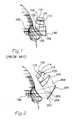
- Figure 1illustrates a prior art head gear display system showing the relative positions of a display source, an optical projection system, and wearer's eye position.
- Figure 2is a head gear display system in accordance with the present invention.
- Figure 3is a diagram illustrating the relationship of the optical components employed in the head gear display system in accordance with the present invention.
- Figure 4is a diagram illustrating the optical rays of the visual image from source to the eye resulting from employment of the optical components illustrated in Figures 2 and 3.
- Figure 5is an illustration generally depicting an observed visual image resulting from the head gear display system in accordance with the present invention.
- Figure 6is an illustration generally depicting an observed visual image resulting from an on-axis head gear display system of the prior art.
- Figure 1illustrates an on-axis optical configuration known in the art and similar to, but not exactly like, that described in U.S. patent 5,303,085, issued to Rallison.
- the head gear display systemgenerally comprises a display source 110, an optical projection system including lens 120 and beam splitter 130, serving to project visual information onto optical combiner means 140, serving as a see-through combiner and also possibly serving as the helmet visor for viewing an external scene.
- the aforesaid constituent components of the head gear display system of the prior artare generally mounted to head gear (not shown). All of the optical components as illustrated in Figure 1 of the prior art are on-axis optical elements. That is, they are symmetrically arranged around the central or optical axis of the optical components, shown folded as illustrated.
- the head gear display system as illustrated in Figure 1operates in the following manner.
- the display source 110for example, a miniature flat panel display source, includes an image surface 112, defining an image plane 114 having a central image reference axis 116 perpendicular to image plane 114.
- Light rays from the visual image emanating from the image plane 114pass first through lens 120, normally employed as a field flattner. In turn, light rays travel to a partially reflecting beam splitter 130 where they are reflected toward partially reflecting surface 142 of optical combiner 140. In turn, these rays are reflected off the partially reflecting surface 142 back toward beam splitter 130, and passing therethrough toward the observer's eye 150, i.e., the wearer of the head gear display system.
- the optical coatings of beam splitter 130 and combiner 140employed in this on-axis mechanization, are likely to be constructed in accordance with one of two possible schemes.
- one approachis to use neutral density coatings with 50% reflection (and therefore 50% transmission) for both beam splitters 130 and combiner 140.
- the other approachis to use narrow spectral band coatings with high reflection coefficient within a spectral band (centered on the spectral output of the display source if it is monochrome, or multiple spectral bands if it is a color display).
- a loss of light transmission efficiencyresults from the multiple rays bouncing off each of the beam splitters and combiner surfaces.
- the transmission lossis not as great, but is still significant, and the color shift of the external scene as viewed by the observer may be objectionable. However, it too contains three reflections in the complete light path (i.e. two reflections off the beam splitter and one reflection off the see-through combiner).
- Figure 2illustrates a head gear display system employing an off-axis optical configuration in accordance with the present invention.
- a display source 110providing an image surface 112 defining an image plane 114 and central image reference axis 116.
- An optical projection systemis provided by way of spherical lenses 220 and 240 for projecting the visual image onto an optical see-through or partially reflective optical combiner 250 through which the observer may view an external scene and simultaneously view the projected visual image provided by the display source.
- Optical combiner 250includes an observer's surface side 252 being generally 50% reflective, and an external scene surface side 254, opposite side 252, generally having anti-reflective coating thereon.
- the projection system of the preferred embodiment of the present inventionemploys only the eccentric portions of lenses 220 and 240 illustrated in Figure 2. This is particularly illustrated in the diagram of Figure 3 which illustrates a side view of complete symmetric spherical lenses 320 and 340 from which the core lenses 220 and 240 would be cut, respectively. Figure 3 further illustrates the optical relationships between the optical components employed in accordance with the present invention.
- FIG. 3again shown is the image plane 114 of the display source and the central image reference axis 116.
- the central lens axis 322 of spherical lens 320is aligned with the central lens axis 342 of spherical lens 340.
- Lenses 320 and 340are oriented such that their respective central lens axes are both decentered and tilted by the angle ⁇ relative to the central image reference axis 116.
- the central axis 256 of the optical combiner 250is decentered and tilted by an angle ⁇ relative to the central lens axes of lenses 320 and 340.
- Figure 4illustrates the optical rays projecting from the image plane 114 successively through core cut lenses 220 and 240, and reflected from the observer's surface side 252 of optical combiner 250 toward the observer's eye 150.
- the simple optical systemcomprised of a pair of lenses and an optical combiner in accordance with the present invention provides a collimating optical system for producing a virtual image at the observer's eye.
- combiner 250is configured as an aspherically shaped toroid, and lenses 220 and 240 which are preferably spherically shaped.
- lenses 220 and 240which are preferably spherically shaped.
- the radii of curvature, thickness, aspheric and spheric coefficients, the chosen optical material, and the relative spacing therebetween, of these optical componentsmust be so selected and arranged to achieve the intended collimation of the virtual image onto the observer's eye. Therefore, the dimensions and orientation of the optical components illustrated in Figure 3 are only exemplary, and other combinations are, of course, possible as known to those skilled in the art.
- the simple optical system illustrated in the Figuresmay be varied within the level of skill in the art, all of which are intended to be in within the scope of the present invention.
- the core cuts of lenses 220 and 240 from lenses 320 and 340, respectivelymay be either spheric or aspheric.
- Toric optical combiner 250(which could be spheric) is aspheric in accordance with the present invention.
- the configuration as illustrated in Figure 2employs only one reflecting surface between the wearer's eye and the external scene (external scene being seen through the see-through combiner 250).
- optical power of the display source visual imageis only reduced by 50% due to the optical combiner 250 beam splitter function achieved by the see-through combiner 250.
- employment of the present inventionimproves light efficiency by as high as a factor of four. This implies that the power required by the display source 110 may be reduced by 75% of that used in the prior art using on-axis optical mechanizations. This is of paramount importance for head gear display systems since if power dissipation is reduced, then the weight needed for heat sink structure is reduced, both of which are of particular importance for battery operated portable systems.
- a second advantage of the present inventionis that it provides additional eye relief compared to the prior art shown in Figure 1. This is so, since eye relief, of course, is defined as the distance between the user's eye and the closest optical elements of the head gear display system. This is of particular importance for those that wear eye glasses to have as much eye relief as is practical.
- eye reliefin a comparison between the prior art of Figure 1 and that of Figure 2, there is greater eye relief in the present invention as compared to the prior art because the optical mechanization of the prior art requires the beam splitter between the eye and the see-through combiner. Whereas in the present invention, the optical combiner is in an unobstructed view of the observer's eye thereby enhancing eye relief.
- Off-axis optical mechanization in accordance with the present inventionmay generally result in an optically distorted image as particularly illustrated in Figure 5 as compared to the optical distortion of a prior art on-axis mechanization as illustrated in Figure 6.
- the off-axis distortion resulting from employment of the optical mechanization in accordance with the present inventionmay be corrected by way of at least two techniques.
- the distortionmay be corrected electronically in the display drive electronics by computing the location of the imagery or symbology in accordance with the predicted distortion pattern similar to that shown in Figure 5 (i.e. predistorting the visual image so that the off-axis mechanization results in being less distorted). Accordingly, when the predistorted visual image generated by the display source has been projected by the optical elements as illustrated, the observer may see the desired non-distorted imagery and/or symbology.
- a second scheme for distortion correctionis to physically alter the image plane of the display means such that after the visual image is projected through the off-axis optical elements, the observer sees generally a normal distortionless visual image.
- the radii of curvature of the aspheric toroid 250employed as the see-through optical combiner 250, are substantially dependent upon there spatial relationships, and particularly the see-through combiner 250--namely, the distance between the observer's eye 150 and the combiner 250 as attached to a particular head gear or helmet.
- the radius of curvature of the optical lenses 220 and 240are equally affected by the configuration, and therefore details thereof have not been described herein and are well understood in the art.
- the radii curvature of the see-through optical combiner 250is selected such that the display appears to be located at infinity as viewed by the observer.
Landscapes
- Physics & Mathematics (AREA)
- General Physics & Mathematics (AREA)
- Optics & Photonics (AREA)
- Lenses (AREA)
Description
Claims (6)
- A head gear display system, intended to be mounted to head gear, forprojecting visual information toward the eye (150) of the wearer of said head gear displaysystem, the head gear display system comprising:one aspheric toricly shaped reflective surface (250) spatially located between theeye of the wearer of the head gear display system and an external scene,said aspheric toricly shaped reflective surface (250) having a centraloptical axis (256) associated therewith;display source means (110) for generating a visual image to provide visualinformation at a display surface (112), and where associated with saiddisplay surface (112) is an image plane (114) and a central imagereference axis (116) perpendicular to said image plane (114); andan optical system arranged between said display source means and said reflective surface and constituted bytwo lenses, namely a first lens (220) and a second lens (240), said first andsecond lenses (220, 240) spatially positioned such that said visual imagepasses successively through said first and second lenses (220, 240) andimpinges on said aspheric toricly shaped reflective surface (250), saidfirst and second lenses (220, 240) each having a central optical axis (322,342) associated therewith and arranged such that said central optical axis(322) of said first lens (220) is aligned with said central optical lens axis(342) of said second lens (340), and said central optical axis (322, 342)of said first and second lenses (220, 240) are both not coaxial and tiltedby an angle α relative to said central image reference axis (116); andsaid aspheric toricly shaped reflective surface (250) is partially reflective andpartially transmissive, and is spatially oriented such that said centraloptical axis (256) associated therewith is tilted by an angle β and notcoaxial relative to said central optical axes (322, 342) of said first andsecond lenses (220, 240), and said aspheric toricly shaped reflectivesurface (250) is configured to reflect, at least in part, said impingingvisual image, thereon, toward the eye of the wearer of said head geardisplay system, said display source means, said reflective surface and said optical system being arranged so that only theeccentric portions of the first and second lenses (220, 240) extendingfrom the central optical axis (322, 342) away from the eye of the wearer are optically operative in imaging said visual image toward the wearer's eye, wherein said eccentric portions of said first and second lenses (320, 340) in combination with said aspheric toricly shaped reflective surface (250) collimate saidvisual image toward said eye of the wearer.
- The head gear display system of claim 1 wherein said first and secondlenses (320, 340) are spherical lenses.
- The head gear display system of claim 1 wherein said display sourcemeans (110) is a flat panel display (110).
- The head gear display system of claim 3 wherein said flat panel display(110) provides a visual image which is intentionally distorted, so as to diminish anyoptical image distortion, as observed by the wearer's eye, resulting from said visualimage passing through said first and second lenses (220, 240) and reflecting from saidaspheric toricly shaped reflective surface (250).
- The head gear display system of claim 1 wherein said aspheric toriclyshaped reflective surface (250) permits said eye of the wearer to simultaneously viewsaid visual image and said external scene.
- The head gear display system of claim 1 wherein said toricly shapedreflective surface (250) is located in an unobstructed view of said eye of the wearer.
Applications Claiming Priority (3)
| Application Number | Priority Date | Filing Date | Title |
|---|---|---|---|
| US493780 | 1995-06-22 | ||
| US08/493,780US5576887A (en) | 1995-06-22 | 1995-06-22 | Head gear display system using off-axis image sources |
| PCT/US1996/010548WO1997001123A2 (en) | 1995-06-22 | 1996-06-19 | Head gear display system |
Publications (2)
| Publication Number | Publication Date |
|---|---|
| EP0834097A2 EP0834097A2 (en) | 1998-04-08 |
| EP0834097B1true EP0834097B1 (en) | 2001-08-08 |
Family
ID=23961684
Family Applications (1)
| Application Number | Title | Priority Date | Filing Date |
|---|---|---|---|
| EP96935773AExpired - LifetimeEP0834097B1 (en) | 1995-06-22 | 1996-06-19 | Head gear display system |
Country Status (6)
| Country | Link |
|---|---|
| US (1) | US5576887A (en) |
| EP (1) | EP0834097B1 (en) |
| JP (1) | JPH11508373A (en) |
| DE (1) | DE69614387T2 (en) |
| IL (1) | IL122309A (en) |
| WO (1) | WO1997001123A2 (en) |
Cited By (3)
| Publication number | Priority date | Publication date | Assignee | Title |
|---|---|---|---|---|
| US9223139B2 (en) | 2013-02-15 | 2015-12-29 | Google Inc. | Cascading optics in optical combiners of head mounted displays |
| US10120194B2 (en) | 2016-01-22 | 2018-11-06 | Corning Incorporated | Wide field personal display |
| US10976551B2 (en) | 2017-08-30 | 2021-04-13 | Corning Incorporated | Wide field personal display device |
Families Citing this family (38)
| Publication number | Priority date | Publication date | Assignee | Title |
|---|---|---|---|---|
| US5303085A (en) | 1992-02-07 | 1994-04-12 | Rallison Richard D | Optically corrected helmet mounted display |
| US5742264A (en)* | 1995-01-24 | 1998-04-21 | Matsushita Electric Industrial Co., Ltd. | Head-mounted display |
| JPH09146038A (en)* | 1995-09-20 | 1997-06-06 | Olympus Optical Co Ltd | Video display device |
| US6204974B1 (en) | 1996-10-08 | 2001-03-20 | The Microoptical Corporation | Compact image display system for eyeglasses or other head-borne frames |
| CA2307877C (en) | 1997-10-30 | 2005-08-30 | The Microoptical Corporation | Eyeglass interface system |
| US6008946A (en)* | 1997-11-07 | 1999-12-28 | Honeywell, Inc. | Ambient light display illumination for a head-mounted display |
| IL132142A0 (en)* | 1998-02-06 | 2001-03-19 | Rodenstock Prazisionsoptil Gmb | Observation or mirroring device |
| DE19809711C1 (en)* | 1998-02-06 | 1999-11-18 | Rodenstock Praezisionsoptik Gm | Optical viewing device for head-up display or helmet-mounted display e.g. for aircraft pilot |
| US6078427A (en)* | 1998-12-01 | 2000-06-20 | Kaiser Electro-Optics, Inc. | Smooth transition device for area of interest head-mounted display |
| US6576924B1 (en)* | 1999-02-12 | 2003-06-10 | Semiconductor Energy Laboratory Co., Ltd. | Semiconductor device having at least a pixel unit and a driver circuit unit over a same substrate |
| US6798579B2 (en)* | 1999-04-27 | 2004-09-28 | Optical Products Development Corp. | Real imaging system with reduced ghost imaging |
| US6598976B2 (en)* | 2001-09-05 | 2003-07-29 | Optical Products Development Corp. | Method and apparatus for image enhancement and aberration corrections in a small real image projection system, using an off-axis reflector, neutral density window, and an aspheric corrected surface of revolution |
| US6935747B2 (en)* | 1999-04-27 | 2005-08-30 | Optical Products Development | Image enhancement and aberration corrections in a small real image projection system |
| US6147807A (en)* | 1999-05-04 | 2000-11-14 | Honeywell, Inc. | High brightness see-through head-mounted display |
| US6724354B1 (en) | 1999-06-21 | 2004-04-20 | The Microoptical Corporation | Illumination systems for eyeglass and facemask display systems |
| HK1046036A1 (en) | 1999-06-21 | 2002-12-20 | The Microoptical Corporation | Eyeglass display lens system employing off-axis optical design |
| US7158096B1 (en) | 1999-06-21 | 2007-01-02 | The Microoptical Corporation | Compact, head-mountable display device with suspended eyepiece assembly |
| WO2000079329A1 (en) | 1999-06-21 | 2000-12-28 | The Microoptical Corporation | Display device with eyepiece assembly and display on opto-mechanical support |
| JP4666723B2 (en) | 1999-07-06 | 2011-04-06 | 株式会社半導体エネルギー研究所 | Method for manufacturing semiconductor device |
| KR100388392B1 (en)* | 2000-10-05 | 2003-06-25 | (주)디오컴 | Head Set of Head Mounted Display |
| GB0105854D0 (en)* | 2001-03-09 | 2001-04-25 | Seos Displays Ltd | Apparatus for improving the collimation quality of a collimated display |
| KR100403079B1 (en)* | 2001-03-10 | 2003-10-30 | 엘지전자 주식회사 | The apparatus of the see-through type head mounted display |
| US7313246B2 (en) | 2001-10-06 | 2007-12-25 | Stryker Corporation | Information system using eyewear for communication |
| DE10310602A1 (en)* | 2003-03-11 | 2004-09-23 | Olympus Biosystems Gmbh | Optical device for optical object examination device has imaging device with mirror providing astigmatic image and pivoted optical component for imaging error reduction |
| GB2415266A (en)* | 2004-06-19 | 2005-12-21 | Francis * Snape Richard | Head up display |
| US7450310B2 (en)* | 2005-05-03 | 2008-11-11 | Optical Research Associates | Head mounted display devices |
| EP1792225A4 (en)* | 2004-09-01 | 2010-07-28 | Optical Res Associates | Compact head mounted display devices with tilted/decentered lens element |
| US20070279541A1 (en)* | 2005-06-29 | 2007-12-06 | Nano Loa, Inc. | Method of driving liquid crystal display device |
| US20070177275A1 (en)* | 2006-01-04 | 2007-08-02 | Optical Research Associates | Personal Display Using an Off-Axis Illuminator |
| US7499217B2 (en)* | 2006-03-03 | 2009-03-03 | University Of Central Florida Research Foundation, Inc. | Imaging systems for eyeglass-based display devices |
| US11640050B2 (en)* | 2011-10-19 | 2023-05-02 | Epic Optix Inc. | Microdisplay-based head-up display system |
| US8786846B2 (en) | 2012-07-05 | 2014-07-22 | Matvey Lvovskiy | Method for determination of head position relative to rectangular axes for observer equipped with head-mounted module |
| RU2540135C1 (en)* | 2014-01-09 | 2015-02-10 | Открытое акционерное общество "Научно-производственное объединение "Государственный институт прикладной оптики" (ОАО "НПО ГИПО") | Imaging system |
| JP6424552B2 (en) | 2014-10-02 | 2018-11-21 | セイコーエプソン株式会社 | Image display device |
| CN106896496B (en)* | 2015-10-30 | 2019-11-08 | 洪维毅 | Field-curvature virtual image display system |
| CN105717643A (en)* | 2016-04-13 | 2016-06-29 | 中山联合光电科技股份有限公司 | A reflective virtual reality optical system |
| CN108986619A (en)* | 2018-08-29 | 2018-12-11 | 天津天堰科技股份有限公司 | A kind of medical training mechanism |
| KR102796870B1 (en) | 2020-05-28 | 2025-04-17 | 삼성전자주식회사 | Holographic display apparatus |
Family Cites Families (18)
| Publication number | Priority date | Publication date | Assignee | Title |
|---|---|---|---|---|
| US3059519A (en)* | 1956-09-05 | 1962-10-23 | Austin N Stanton | Headgear mounted cathode ray tube and binocular viewing device |
| US3787109A (en)* | 1972-06-28 | 1974-01-22 | Honeywell Inc | Inside helmet sight apparatus |
| GB1533859A (en)* | 1975-04-29 | 1978-11-29 | Elliott Bros | Headgear incorporating optical display systems |
| US4026641A (en)* | 1975-12-30 | 1977-05-31 | The United States Of America As Represented By The Secretary Of The Army | Toric reflector display |
| GB1527049A (en)* | 1976-06-18 | 1978-10-04 | Pilkington Perkin Elmer Ltd | Head-up displays |
| US4361384A (en)* | 1980-06-27 | 1982-11-30 | The United States Of America As Represented By The Secretary Of The Army | High luminance miniature display |
| US4465347A (en)* | 1982-11-15 | 1984-08-14 | The United States Of America As Represented By The Secretary Of The Air Force | Helmet mounted telescope |
| US4968117A (en)* | 1983-09-02 | 1990-11-06 | Hughes Aircraft Company | Graded index asperhic combiners and display system utilizing same |
| US5035474A (en)* | 1984-04-16 | 1991-07-30 | Hughes Aircraft Company | Biocular holographic helmet mounted display |
| US4755023A (en)* | 1986-10-27 | 1988-07-05 | Kaiser Aerospace And Electronics Corporation | Headgear mounted display visor |
| US4950567A (en)* | 1988-01-15 | 1990-08-21 | E. I. Du Pont De Nemours And Company | Holographic optical combiners for head-up displays |
| FR2662894B1 (en)* | 1990-06-01 | 1995-11-17 | Thomson Csf | DEVICE FOR VIEWING SIMULATED IMAGES FOR A HELMET. |
| US5151722A (en)* | 1990-11-05 | 1992-09-29 | The Johns Hopkins University | Video display on spectacle-like frame |
| IL99420A (en)* | 1991-09-05 | 2000-12-06 | Elbit Systems Ltd | Helmet mounted display |
| US5303085A (en)* | 1992-02-07 | 1994-04-12 | Rallison Richard D | Optically corrected helmet mounted display |
| JP3155360B2 (en)* | 1992-07-27 | 2001-04-09 | オリンパス光学工業株式会社 | Visual display device |
| US5499139A (en)* | 1993-10-01 | 1996-03-12 | Hughes Aircraft Company | Ultra-wide field of view, broad spectral band helmet visor display optical system |
| US5416876A (en)* | 1994-01-28 | 1995-05-16 | Hughes Training, Inc. | Fiber optic ribbon subminiature display for head/helmet mounted display |
- 1995
- 1995-06-22USUS08/493,780patent/US5576887A/ennot_activeExpired - Lifetime
- 1996
- 1996-06-19JPJP9503905Apatent/JPH11508373A/ennot_activeCeased
- 1996-06-19WOPCT/US1996/010548patent/WO1997001123A2/enactiveIP Right Grant
- 1996-06-19DEDE69614387Tpatent/DE69614387T2/ennot_activeExpired - Fee Related
- 1996-06-19EPEP96935773Apatent/EP0834097B1/ennot_activeExpired - Lifetime
- 1996-06-19ILIL12230996Apatent/IL122309A/ennot_activeIP Right Cessation
Cited By (4)
| Publication number | Priority date | Publication date | Assignee | Title |
|---|---|---|---|---|
| US9223139B2 (en) | 2013-02-15 | 2015-12-29 | Google Inc. | Cascading optics in optical combiners of head mounted displays |
| US10120194B2 (en) | 2016-01-22 | 2018-11-06 | Corning Incorporated | Wide field personal display |
| US10649210B2 (en) | 2016-01-22 | 2020-05-12 | Corning Incorporated | Wide field personal display |
| US10976551B2 (en) | 2017-08-30 | 2021-04-13 | Corning Incorporated | Wide field personal display device |
Also Published As
| Publication number | Publication date |
|---|---|
| DE69614387D1 (en) | 2001-09-13 |
| IL122309A (en) | 2001-01-11 |
| IL122309A0 (en) | 1998-04-05 |
| US5576887A (en) | 1996-11-19 |
| WO1997001123A2 (en) | 1997-01-09 |
| WO1997001123A3 (en) | 1997-02-27 |
| DE69614387T2 (en) | 2002-05-23 |
| EP0834097A2 (en) | 1998-04-08 |
| JPH11508373A (en) | 1999-07-21 |
Similar Documents
| Publication | Publication Date | Title |
|---|---|---|
| EP0834097B1 (en) | Head gear display system | |
| EP0284389B1 (en) | Helmet mounted display systems | |
| US6147807A (en) | High brightness see-through head-mounted display | |
| US5035474A (en) | Biocular holographic helmet mounted display | |
| US5257094A (en) | Helmet mounted display system | |
| US5309169A (en) | Visor display with fiber optic faceplate correction | |
| US5991087A (en) | Non-orthogonal plate in a virtual reality or heads up display | |
| US5619377A (en) | Optically corrected helmet mounted display | |
| US5822127A (en) | Low-cost light-weight head-mounted virtual-image projection display with low moments of inertia and low center of gravity | |
| US4026641A (en) | Toric reflector display | |
| US4218111A (en) | Holographic head-up displays | |
| US5418584A (en) | Retroreflective array virtual image projection screen | |
| US6097543A (en) | Personal visual display | |
| EP0179124B1 (en) | Binocular holographic helmet mounted display | |
| WO1991004508A2 (en) | Helmet mounted display | |
| US5838490A (en) | Head mounted display system using mangin mirror combiner | |
| EP0579506A1 (en) | Helmet-mounted biocular display system | |
| EP4296745A1 (en) | Optical device and method | |
| GB2619969A (en) | Optical device and method | |
| GB2619968A (en) | Optical device and method | |
| GB2619967A (en) | Optical device and method | |
| WO2000014585A1 (en) | Display system |
Legal Events
| Date | Code | Title | Description |
|---|---|---|---|
| PUAI | Public reference made under article 153(3) epc to a published international application that has entered the european phase | Free format text:ORIGINAL CODE: 0009012 | |
| 17P | Request for examination filed | Effective date:19971017 | |
| AK | Designated contracting states | Kind code of ref document:A2 Designated state(s):DE FR GB | |
| 17Q | First examination report despatched | Effective date:19990722 | |
| GRAG | Despatch of communication of intention to grant | Free format text:ORIGINAL CODE: EPIDOS AGRA | |
| GRAG | Despatch of communication of intention to grant | Free format text:ORIGINAL CODE: EPIDOS AGRA | |
| GRAH | Despatch of communication of intention to grant a patent | Free format text:ORIGINAL CODE: EPIDOS IGRA | |
| GRAH | Despatch of communication of intention to grant a patent | Free format text:ORIGINAL CODE: EPIDOS IGRA | |
| GRAA | (expected) grant | Free format text:ORIGINAL CODE: 0009210 | |
| AK | Designated contracting states | Kind code of ref document:B1 Designated state(s):DE FR GB | |
| REF | Corresponds to: | Ref document number:69614387 Country of ref document:DE Date of ref document:20010913 | |
| PG25 | Lapsed in a contracting state [announced via postgrant information from national office to epo] | Ref country code:DE Free format text:LAPSE BECAUSE OF FAILURE TO SUBMIT A TRANSLATION OF THE DESCRIPTION OR TO PAY THE FEE WITHIN THE PRESCRIBED TIME-LIMIT Effective date:20011109 | |
| REG | Reference to a national code | Ref country code:GB Ref legal event code:IF02 | |
| ET | Fr: translation filed | ||
| PLBE | No opposition filed within time limit | Free format text:ORIGINAL CODE: 0009261 | |
| STAA | Information on the status of an ep patent application or granted ep patent | Free format text:STATUS: NO OPPOSITION FILED WITHIN TIME LIMIT | |
| 26N | No opposition filed | ||
| PGFP | Annual fee paid to national office [announced via postgrant information from national office to epo] | Ref country code:GB Payment date:20050506 Year of fee payment:10 | |
| PGFP | Annual fee paid to national office [announced via postgrant information from national office to epo] | Ref country code:FR Payment date:20050602 Year of fee payment:10 | |
| PGFP | Annual fee paid to national office [announced via postgrant information from national office to epo] | Ref country code:DE Payment date:20050630 Year of fee payment:10 | |
| PG25 | Lapsed in a contracting state [announced via postgrant information from national office to epo] | Ref country code:GB Free format text:LAPSE BECAUSE OF NON-PAYMENT OF DUE FEES Effective date:20060619 | |
| GBPC | Gb: european patent ceased through non-payment of renewal fee | Effective date:20060619 | |
| REG | Reference to a national code | Ref country code:FR Ref legal event code:ST Effective date:20070228 | |
| PG25 | Lapsed in a contracting state [announced via postgrant information from national office to epo] | Ref country code:FR Free format text:LAPSE BECAUSE OF NON-PAYMENT OF DUE FEES Effective date:20060630 | |
| P01 | Opt-out of the competence of the unified patent court (upc) registered | Effective date:20230525 |