EP0830562B1 - Magnetic location system with adaptive feedback control - Google Patents
Magnetic location system with adaptive feedback controlDownload PDFInfo
- Publication number
- EP0830562B1 EP0830562B1EP96917933AEP96917933AEP0830562B1EP 0830562 B1EP0830562 B1EP 0830562B1EP 96917933 AEP96917933 AEP 96917933AEP 96917933 AEP96917933 AEP 96917933AEP 0830562 B1EP0830562 B1EP 0830562B1
- Authority
- EP
- European Patent Office
- Prior art keywords
- sensor
- field
- coil
- sensors
- fields
- Prior art date
- Legal status (The legal status is an assumption and is not a legal conclusion. Google has not performed a legal analysis and makes no representation as to the accuracy of the status listed.)
- Expired - Lifetime
Links
- 230000003044adaptive effectEffects0.000title1
- 238000000034methodMethods0.000claimsdescription20
- 238000004364calculation methodMethods0.000claimsdescription11
- 230000005355Hall effectEffects0.000claimsdescription3
- 230000004907fluxEffects0.000claimsdescription2
- 238000005070samplingMethods0.000claimsdescription2
- 230000001771impaired effectEffects0.000claims2
- 230000003247decreasing effectEffects0.000claims1
- 230000000977initiatory effectEffects0.000claims1
- 230000005540biological transmissionEffects0.000abstract1
- 239000000523sampleSubstances0.000description25
- 239000011159matrix materialSubstances0.000description13
- 239000003550markerSubstances0.000description9
- 238000013459approachMethods0.000description7
- 238000003384imaging methodMethods0.000description7
- 230000003321amplificationEffects0.000description6
- 230000006870functionEffects0.000description6
- 238000003199nucleic acid amplification methodMethods0.000description6
- 230000008569processEffects0.000description6
- 230000004044responseEffects0.000description6
- 230000008859changeEffects0.000description5
- 238000006243chemical reactionMethods0.000description5
- 230000035945sensitivityEffects0.000description5
- 238000013519translationMethods0.000description5
- 230000008901benefitEffects0.000description4
- 238000012937correctionMethods0.000description3
- 238000012544monitoring processMethods0.000description3
- 230000009466transformationEffects0.000description3
- 238000004422calculation algorithmMethods0.000description2
- 238000013461designMethods0.000description2
- 238000010586diagramMethods0.000description2
- 238000001914filtrationMethods0.000description2
- 238000002595magnetic resonance imagingMethods0.000description2
- 238000012546transferMethods0.000description2
- 101100480514Caenorhabditis elegans tag-53 geneProteins0.000description1
- 239000004020conductorSubstances0.000description1
- 230000008878couplingEffects0.000description1
- 238000010168coupling processMethods0.000description1
- 238000005859coupling reactionMethods0.000description1
- 238000009795derivationMethods0.000description1
- 230000005672electromagnetic fieldEffects0.000description1
- 230000007613environmental effectEffects0.000description1
- 238000002594fluoroscopyMethods0.000description1
- 230000036541healthEffects0.000description1
- 230000006872improvementEffects0.000description1
- 230000005865ionizing radiationEffects0.000description1
- 239000000463materialSubstances0.000description1
- 238000012067mathematical methodMethods0.000description1
- 238000012545processingMethods0.000description1
- 230000000750progressive effectEffects0.000description1
- 239000007787solidSubstances0.000description1
- 238000000844transformationMethods0.000description1
- 230000001131transforming effectEffects0.000description1
Images


Classifications
- A—HUMAN NECESSITIES
- A61—MEDICAL OR VETERINARY SCIENCE; HYGIENE
- A61B—DIAGNOSIS; SURGERY; IDENTIFICATION
- A61B5/00—Measuring for diagnostic purposes; Identification of persons
- A61B5/06—Devices, other than using radiation, for detecting or locating foreign bodies ; Determining position of diagnostic devices within or on the body of the patient
- A61B5/061—Determining position of a probe within the body employing means separate from the probe, e.g. sensing internal probe position employing impedance electrodes on the surface of the body
- A61B5/062—Determining position of a probe within the body employing means separate from the probe, e.g. sensing internal probe position employing impedance electrodes on the surface of the body using magnetic field
- A—HUMAN NECESSITIES
- A61—MEDICAL OR VETERINARY SCIENCE; HYGIENE
- A61B—DIAGNOSIS; SURGERY; IDENTIFICATION
- A61B5/00—Measuring for diagnostic purposes; Identification of persons
- A61B5/06—Devices, other than using radiation, for detecting or locating foreign bodies ; Determining position of diagnostic devices within or on the body of the patient
- A61B5/061—Determining position of a probe within the body employing means separate from the probe, e.g. sensing internal probe position employing impedance electrodes on the surface of the body
- A61B5/064—Determining position of a probe within the body employing means separate from the probe, e.g. sensing internal probe position employing impedance electrodes on the surface of the body using markers
- G—PHYSICS
- G01—MEASURING; TESTING
- G01B—MEASURING LENGTH, THICKNESS OR SIMILAR LINEAR DIMENSIONS; MEASURING ANGLES; MEASURING AREAS; MEASURING IRREGULARITIES OF SURFACES OR CONTOURS
- G01B7/00—Measuring arrangements characterised by the use of electric or magnetic techniques
- G01B7/004—Measuring arrangements characterised by the use of electric or magnetic techniques for measuring coordinates of points
- A—HUMAN NECESSITIES
- A61—MEDICAL OR VETERINARY SCIENCE; HYGIENE
- A61B—DIAGNOSIS; SURGERY; IDENTIFICATION
- A61B34/00—Computer-aided surgery; Manipulators or robots specially adapted for use in surgery
- A61B34/20—Surgical navigation systems; Devices for tracking or guiding surgical instruments, e.g. for frameless stereotaxis
- A61B2034/2046—Tracking techniques
- A61B2034/2051—Electromagnetic tracking systems
Definitions
- the present inventionrelates to systems for determining the location and/or orientation of objects in space by detecting magnetic fields.
- Various systemshave been proposed for detecting the position and/or orientation of an object using magnetic or electromagnetic fields. These systems typically employ field transmitters, such as electromagnet coils, disposed at known locations in a fixed reference frame and a sensor, such as a coil or other transducer mounted to the object to be located. Each transmitter projects a field varying in space in a fixed frame of reference. The pattern of variation in space for each transmitter is different than the pattern for each other transmitter. For example the transmitters may be identical to one another but disposed at different locations or in different orientations. The field patterns of the transmitters are thus displaced or rotated relative to one another and relative to the fixed frame of reference.
- field transmitterssuch as electromagnet coils
- a sensorsuch as a coil or other transducer mounted to the object to be located.
- Each transmitterprojects a field varying in space in a fixed frame of reference.
- the pattern of variation in space for each transmitteris different than the pattern for each other transmitter.
- the transmittersmay be identical to one another but disposed at different locations
- the sensor on the objectdetects the parameters of the field prevailing at the location of the object as, for example, the magnitude and/or direction of the field at the object or the magnitudes of individual components of the field at the object in one or more preselected directions.
- the transmittersmay be actuated in a predetermined sequence so that at any time only one transmitter is active and therefore the field prevailing at the object is only the field contributed by one transmitter, plus a background field due to the Earth's magnetic field and other environmental sources.
- the transmitterscan be driven at different frequencies so that components of the signal from the sensor varying at different frequencies represent contributions to the field at the object from different transmitters.
- a computer systemcalculates the position and orientation of the sensor, and hence the position of the object bearing the sensor, in the fixed frame of reference of the transmitters.
- the object to be locatedcarries the transmitter or transmitters, whereas a plurality of sensors are disposed at various locations or orientations in the fixed frame of reference. The location and/or orientation of the object is deduced from signals representing the parameters of the field prevailing at the various sensors.
- Systems of this general natureare disclosed in United States Patents 4,849,692 ; 4,642,786 ; 4,710,708 ; 4,613,866 and 4,945,305 .
- Systems according to this general designcan be used to provide a three-dimensional spatial input capability for a computer.
- Another system of this natureis disclosed in International Patent publication WO94/04938 .
- the object to be locatedmay be a medical endoscope.
- Such a systemmay include a sensor mounted on the tip of an endoscope, so that the location and/or orientation of the endoscope tip can be determined while the sensor is disposed inside the body of a medical patient.
- the '938 publicationcontemplates an arrangement in which plural transmitting coils are actuated simultaneously to "steer" the direction of the resulting field and thereby align the field with the sensor.
- the '938 publicationcharacterizes this arrangement as undesirable.
- Other systems for locating medical instrumentssuch as endoscopes and catheters based upon transmitted fields are disclosed in United States Patent No. 5,042,486 ; 5,099,845 ; 5,211,165 ; 5,251,635 ; 5,253,647 ; 5,255,680 ; 5,265,610 and 5,391,199 .
- Systems of this naturetypically have used fields having strength which varies as the third power, or a higher power, of distance from the transmitter. There is, accordingly, a very large variation in the strength of each field from location to location.
- the field strengthmay vary through many orders of magnitude from one end of the sensing volume to another.
- US 4,652,820discloses a combined magnetic sensor and actuator device for applying a magnetic force to a magnetizable body and for sensing the distance between the device and the magnetizable body.
- the apparatusincludes a low frequency electric current source, a high electric current source, a detector and a magnetizable pole piece which interacts with a body provided on a shaft.
- the low frequency current sourceprovides an actuating signal which maintains the shaft at a desired position or moves it in a desired manner.
- High frequency current source and detectorare utilized to detect the position of the shaft.
- WO 92/05543discloses servo control systems for controlling the head positioning actuators in storage devices such as disk drives.
- One aspect of the present inventionprovides apparatus for determining position including field generating means for producing a plurality of magnetic fields.
- the field generating meansis arranged to provide such fields having parameters, such as field strength and/or field direction, varying with location within a sensing volume according to known patterns of variation.
- the pattern of variation for each fieldis different than the pattern of variation for each other field.
- the field generating meansincludes a plurality of transmitting coils
- the coilsare disposed at different locations and/or different orientations relative to the sensing volume.
- Apparatus according to this aspect of the inventionalso includes at least one sensor adapted to detect one or more parameters of the field prevailing at the sensor when the sensor is at an unknown location within the sensing volume, and to provide one or more sensor signals representing such detected parameters.
- the senormay include a sensor body and a plurality of component sensors disposed on the sensor body, each component sensor being operative to measure the magnitude of a magnetic field component in a preselected local direction relative to the sensor body to provide a component sensor signal representing that particular component of the field prevailing at the sensor.
- the apparatusfurther includes calculation means for calculating the location of the sensor, the orientation of the sensor or both based upon the sensor signals and upon the unknown patterns of variation of the fields.
- the apparatusalso includes feedback control means for adjusting the field generating means to alter the known pattern of variation of at least one of the fields responsive to the sensor signals, to the calculated location of the sensor or both so as to maintain the detected parameters of the altered field at the sensor within a preselected range.
- the feedback control meanscan be arranged to increase the strength of the field transmitted by a particular transmitter when the sensor is remote from such transmitter, and to decrease the strength of the field emitted by that transmitter when the sensor is close to the transmitter.
- the parameters of the field detected at the location of the sensorwill always lie within a relatively narrow range of values. Because the transmitted field is altered in a known manner, the position and/or orientation of the sensor can still be calculated, simply by using the altered field as the basis for calculation. For example, where the feedback control means increases the current flowing to an electromagnetic coil, the parameters used in the calculation to represent the strength of the field emitted from that particular coil are adjusted accordingly.
- Apparatuscan maintain the detected field parameters at the sensor location, such as the magnitude of the field at such location, within a relatively narrow range even where the field strength varies with a power of distance greater than the first power as, for example, where the field strength varies with the third power of distance from the coil.
- the systemtherefore can provide good signal to noise ratio, even with a very small sensor.
- a plurality of individual coilsmay be disclosed at various locations beneath a patient receiving bed, or on one side of the bed.
- apparatuscan utilize any type of sensor, it has additional advantages when used with magnetoresistive sensors or other sensors which can lose accuracy when exposed to very high magnetic fields. Because the field is maintained within a relatively narrow range, the sensors are not exposed to fields which would impair their accuracy.
- the feedback control systemis actuated to maintain the parameters of the field at each sensor within the narrowest attainable range of values. Thus, the feedback control maintains the field parameters at the sensor at substantially constant values.
- the transmitted fieldsare altered in a known manner, and the disposition of the sensor can still be calculated by using the altered fields as the basis for calculation.
- a further aspect of the present inventionprovides apparatus including at least one transmitter adapted for mounting to the object to be located and also including a plurality of sensors disposed adjacent a sensing volume.
- the apparatusincludes calculation means for determining a calculated location of the transmitter based upon signals from the sensors and upon the known pattern of variation of the field at the transmitter.
- feedback control meansare provided for adjusting the field generating means to alter the known pattern of variation of field sent by the at least one transmitter in response to the sensor signal, to the calculated location of the transmitter or both so as to maintain the parameters of the field from the at least one transmitter prevailing at each sensor within a preselected range.
- This arrangementis similar to the arrangement discussed above, except that the transmitter or transmitters are disposed on the object to be located whereas the sensors are located in the fixed frame of reference of the sensing volume.
- the transmitterwhen the transmitter is close to the sensor, or where the orientations of the transmitter and sensor favor strong coupling between the transmitted field and the sensor, the strength of the field is reduced. If the transmitter is relatively far from the sensor, or in a unfavorable orientation, the control means increases the strength of the transmitted field.
- a further aspect of the inventionprovides apparatus for sensing the disposition of an object--its position, orientation or both--in a frame of reference.
- Apparatus according to this aspect of the inventionincludes transmitter means including at least one transmitter for providing a field and sensor means including at least one sensor for sensing one or more parameters of a field prevailing at each such sensor and providing one or more sensor signals indicative of such parameters.
- the transmitter means and said sensor meanscooperatively define a plurality of transmitter-sensor pairs, each including one transmitter and one sensor as elements of the pair, one element of each such pair being disposed on the object and the other element of each such pair being disposed at a known disposition in said frame of reference.
- each transmitter-sensor pairis disposed at a different position or orientation than the corresponding element of the other pairs.
- the apparatusfurther includes calculation means for determining the disposition of said object based upon said sensor signals feedback control means for adjusting said transmitting means responsive to said sensor signals to thereby maintain at least one of said sensor signals within a preselected range.
- Apparatus in accordance with one embodiment of the present inventionincludes three generally helical transmitter coils 10 disposed in a common plane. Coils 10 are mounted in fixed position in the frame of reference of patient receiving bed 12. That frame of reference is denoted by a Cartesian coordinate system X, Y, Z as shown in Fig. 1 .
- a patient Pmay be positioned on the patient receiving bed.
- the axes 11 of the coilsare parallel to one another.
- a patient receiving bed 12extends just above the plane of coil 10.
- the apparatusfurther includes an object or probe 14.
- the probeis adapted to be inserted into a medical instrument such as a catheter 16 and positioned at a desired location in the catheter, such as at the distal tip of the catheter or at another location along the length of the catheter.
- Probe 14has mounted thereon a sensor 18.
- Sensor 18includes three component sensors 20, 22 and 24 adapted to sense components of the magnetic field in mutually orthogonal local directions X', Y' and Z'. That is, component sensor 20 is sensitive to magnetic fields directed in direction X', but largely insensitive to fields in directions Y' and Z', whereas sensor 22 is sensitive only to fields in direction Y' and sensor 24 is sensitive to fields in direction Z'. These sensors are adapted to provide separate sensor signals representing the separate components.
- Sensor 18may be a solid state sensor of the type described in the aforementioned International Patent Publication WO95/09562 .
- each of the component sensorsmay include a generally planar magnetically sensitive film, such as a magneto-resistive film or a Hall effect sensing film. Each such film may be sensitive to fields directed normal to the plane of the film.
- sensor 18may include an array of miniature coils, the axes of the coils being oriented orthogonal to one another. Although these represent the preferred sensors, essentially any other magnetically sensitive device may be employed as, for example, magneto-optical sensors and flux gate magnetometers.
- Command unit 28( Fig. 3 ) includes an input amplification and analog to digital (“A/D") conversion section 30 adapted to receive the individual signals from component sensors 20, 22 and 24 of sensor 18, amplify the same and convert the same to digital form.
- the amplification and A/D conversion unit 30may also include other conventional signal processing devices such as analog or digital band pass filtering and noise rejection devices and signal averagers.
- Command unit 28further includes a computation unit 32.
- Computation unit 32may be implemented as a programmed general purpose computer. As further discussed below, the position computation unit is arranged to compute the disposition of sensor 18, and hence the disposition of the object or probe 14 at the catheter tip from the sensor signals.
- the term "disposition" of an elementrefers to the position of the element, the orientation of the element or both.
- the computation unitis arranged to calculate the position of sensor 18, the orientation of the sensor, or, preferably, both position and orientation.
- Command unit 28may be linked to a display device (not shown) for providing a human intelligible representation of the position of the probe or object 14.
- human intelligible representationmay be provided either as numerical information presenting the position and/or orientation of object 14 in the X, Y, Z coordinate system or, preferably, as a pictorial representation of the object and of the associated catheter superposed on a pictorial representation of the patient .
- Command unit 28further includes a control unit 34.
- Control unit 34is linked by output lines 36, 38 and 40 to three separate coil drivers 42, 44 and 46.
- Each coil driveris linked to a separate one of transmitter coils 10.
- Each coil driveris adapted to send a direct current through the associated transmit coil 10.
- Each coil driveris arranged to control the amplitude of such current, and to turn the current on or off, in response to control signals received from control unit 34.
- the control unitis arranged to signal the coil drivers to provide currents to their respective transmit coils in alternating sequence, so that coil 10a receives current while coils 10b and 10c are inactive; coil 10b receives current while coils 10a and 10c are inactive and coil 10c receives current while coils 10a and 10b are inactive.
- the control unitreceives data from amplification and conversion section 30 and, as further discussed below, actuates the coil drivers to vary the amplitude of the current to each coil.
- the control unitmay include conventional interface devices such as digital to analog converters or bus interface units so that the output of the control unit is compatible with the control input of each coil driver.
- the control unitis illustrated separately from the other logical units of command unit 28, it should be appreciated that the control unit may share physical elements of the command unit and other elements.
- the processor of the computermay serve both as an element of the position computation unit and as an element of the control unit, executing functions appropriate to the different units at different times.
- an catheter 16is advanced into the body of a patient P.
- the probe 14 with sensor 18 thereonis disposed at the tip of the catheter.
- the catheter tipis disposed at an unknown location somewhere above the plane of coils 10.
- Control unit 34actuates the coil drivers in sequence, using an initial or default value for the current amplitude to be provided to each coil 10.
- Amplification and conversion unit 30samples the signal from each of the component sensors 20, 22 and 24 at a preselected time after the beginning of current flow through each coil. For example, at a preselected time after the beginning of current flow through transmit coil 10a, unit 30 takes a sample of the signal from each of component sensors 20, 22 and 24, and converts the same to digital format.
- Command unit 28then calculates a total field magnitude based upon these individual signals.
- the total field magnitudeis:
- ( k 20 ⁇ S 20 ⁇ ) 2 + ( k 22 ⁇ S 22 ⁇ ) 2 + ( k 24 ⁇ S 24 ⁇ ) 2 where:
- the systemactuates coils 10b and 10c in order, using the default current strength.
- the systemcomputes the magnitude of the total field vector prevailing at the sensor during actuation of coil 10b and independently computes the magnitude of the total field vector prevailing at the sensor during actuation of coil 10c.
- the control unitdetermines whether or not all of the field magnitudes are within a preselected range of magnitudes.
- This preselected rangeis chosen to lie within the optimum operating range of sensor 18.
- the minimum field magnitudeis selected to lie well above the noise threshold of the system and above the minimum sensitivity level of the sensor, where the maximum field level is selected to lie well below the maximum limit of linearity of the sensor, and well below the maximum field which the sensor can tolerate without loss of accuracy.
- the preselected range of field magnitudesmay be from about 1.0 to about 2.5 Gauss. With typical Hall effect sensors, which are most accurate when used with fields over about 30 Gauss, the preselected range will be above about 30 Gauss. If the three field vector magnitudes observed during actuation of the three units 10a, 10b and 10c all lie within the preselected range, than the system proceeds to calculate the position and orientation of sensor 18, and hence the position and orientation of probe 14 and the associated tip 16 of the catheter using conventional position finding algorithms.
- the mathematical methods disclosed in United States Patent 4,710,708 for finding positions using a multiple transmitting or receiving stations and a multi-axis sensorcan be employed.
- the magnitude of the fields in each of the local or sensor directions X', Y', Z' represented by each of the component sensor signals from each of the component sensors 20, 22 and 24is a function of the overall strength of the field from the coil (also referred to as the magnetic dipole moment of the coil), the distance from the particular coil to the sensor and the sensor rotation angles, i.e., the angles between the local directions X', Y' and Z' and the coil frame of reference directions X, Y and Z.
- control unit 34changes the field strength of the coil or coils associated with the out-of-range field strength. For example, where probe 14 and sensor 18 are relatively close to coil 10a, the total field magnitude detected when coil 10a is actuated will be above the preselected range. Control unit 34 therefore will command coil driver 42 to reduce the current to coil 10a on the next actuation cycle. Conversely, if the probe and sensor are relatively far from coil 10c, the field magnitude sensed during actuation of coil 10c with the default of current value will be below the preselected range. Control unit 34 therefore will instruct coil driver 46 to increase the current to coil 10c on the next actuation cycle.
- the coil driversmay be arranged to vary the overall field strength or dipole moment of each coil stepwise, as by varying the current stepwise.
- Each increase or decrease commanded by control unit 34may be one step.
- the control unitcan calculate an increase or decrease proportional to the degree to which the total field magnitude deviates from a target value within the preselected range.
- a relatively large changecan be made when the field magnitude is far outside of the range, whereas a smaller change can be employed when the field magnitude is close to the range or within the range.
- the correction processcontinues until all field strengths are within the preselected range, whereupon the system calculates position and orientation. After the system finds values of coil currents which produce field magnitudes within the range, subsequent actuation cycles use these currents.
- the position of the catheter tip, and hence the position of probe 14 and sensor 18may change. Any such change may bring one or more of the field magnitudes outside of the preselected range, whereupon the system will readjust the currents to the coils once again.
- the feedback control unitreadjusts the currents to the coils, the altered values of current are translated into new values for field strengths from the individual coils which are used in the aforementioned position determining equations.
- the systemassures that the sensor is always exposed to a field having a magnitude within the preselected range wherever the sensor is placed within a sensing volume 50 extending over a preselected region above the plane of coils 10.
- the exact size of sensing volume 50will depend upon the breadth of the preselected field magnitude range and the dynamic range of coil drivers 42, 44 and 46, i.e., the degree to which the coil drivers can vary the currents.
- sensing volume 50within which the sensor will receive fields within the preselected field magnitude range from all coils will also depend upon the positions of the coils. However, for a typical system having three coils spaced at vertices of an equilateral triangle with sides about 40 cm long, the sensing volume includes a region extending upwardly about 60 cm from the plane of the coils. At the plane of the coils, the sensing volume extends about 20 cm beyond the equilateral triangle bounded by the coils.
- each fiducial markermay include a sensor body 52, a tag 53 and a sensor 54 of the same type as sensor 18 releasably connected to the sensor body.
- the amplification and converson unit 30is connected to each of these additional sensors in the same manner as to sensor 18.
- the tag of each sensormay be affixed to the body of the patient, and an image of the patient may be acquired using any imaging method which will show the desired structures of the patient's body and which will also show the tags 53 as, for example, magnetic resonance imaging (MRI), X-ray, CAT scanning or the like.
- the tagsare constructed to facilitate imaging in the desired imaging method.
- MRImagnetic resonance imaging
- the tagmay be radioopaque
- the tagmay include a material which has magnetic resonance response readily distinguishable from that of bodily tissue.
- the imageis acquired prior to use of the catheter and probe discussed above.
- the sensors 54typically are not present in the imaging step.
- the sensor bodies 54 and sensors of the fiducial markersare attached to the patient's body at the positions of the tags.
- sensor signals from sensor 18 on the probe in the catheterare acquired concurrently with signals from the sensor 52 on the fiducial markers.
- the systemdetermines the location and orientation of sensor 54, and hence of fiducial markers 52 using magnetic fields from coils 10 in the same manner as the system determines the position and orientation of sensor 18 and probe 14.
- the acquired position and orientation of the fiducial markers 52can be used to register the previously acquired image of the patient with the position and orientation data for sensor 18 and probe 14.
- the position and orientation data for the sensor 18 and probe 14are displayed as a pictorial image of the catheter tip 16 on a screen
- the position and orientation of fiducial markers, as determined by the magnetic field locating methodcan also be displayed.
- the previously acquired image datamay be displayed as a pictorial representation of the patient's structures and that representation will also include a picture of the tags 53.
- the previously acquired images of the tagsare brought into registration with the images of the fiducial markers derived from magnetic location by transforming one or the other image until the picture of the tags in the previously acquired image overlies the representation of the fiducial marker in the magnetically acquired image.
- Such registrationcan be achieved by manually adjusting inputs to an image display system while visually matching the displayed images, as described in the aforementioned '562 International Publication. or else by automatic calculation of the transformation and rotation parameters necessary to bring the images into registration.
- Such parameterscan be calculated by equating the positions of three or more fiducial marker sensors in the magnetic location frame of reference (the X,Y,Z coordinates of Fig. 1 ) with the positions of the tags 53 in the image frame of reference as modified by a matrix of unknown rotations a further matrix of unknown transformations.
- the resulting matrix equationyields an overdetermined system of nonlinear equations which include the rotation angles and transformation distances.
- the coilsmay be operated in separate cycles so as to provide each sensor with fields having magnitudes in the preselected range appropriate for the sensor.
- control unit 34may actuate the coil drivers 42, 44 and 46, and hence transmitting coils 10, in first, second, third and fourth cycles.
- the signals from sensor 18are acquired and the signals from sensors 54 of the fiducial markers are ignored.
- the coilcurrently is adjusted to yield field magnitudes at sensor 18 within the preselected range as discussed above.
- the signals from the sensor 54a of a first fiducial markerare acquired, the signals from sensor 18 and the other fiducial marker sensors 54b, 54c are ignored and the coil currents are adjusted to provide a field magnitude at sensor 54a within its preselected range.
- the signals from sensor 54bare acquired whereas the other signals are ignore; in the fourth cycle, the signals from sensor 54c are acquired and others are ignored.
- the cyclesmay be sequential, with the entirety of a first cycle being performed before the entirety of a second cycle.
- the cyclesmay also be interspersed with one another.
- coil driver 42can be actuated first to provide a current appropriate to yield the proper field at the first sensor 18 and then can be actuated to provide the appropriate fields at the fiducial marker sensors 54a, 54b and 54c in succession, followed by a similar multiple actuation of the other coils.
- the number of cyclesmay be less than the number of sensors.
- the currents used on a given cyclemay be adjusted to provide fields within the desired range of magnitude for one sensor.
- Signals from other sensorcan be acquired during this cycle, although such other sensor may encounter a field outside the preselected range.
- the coil currentsare fixed for some cycles and adjusted for others. For example, where numerous fiducial markers are employed, it may be possible to achieve acceptable registration accuracy using fixed coil currents to provide the fields when data is acquired from the fiducial markers, whereas the coil currents may be adjusted in the manner discussed above when data is acquired from the sensor in the active device or catheter.
- Certain sensorstend to lose accuracy when exposed to magnetic fields above a predetermined maximum. For example, certain magneto-resistive sensors temporarily lose accuracy if exposed to magnetic fields above about 4 Gauss. Where such sensors are employed in a multi-sensor system, the system should have appropriate provisions to avoid exposing sensors to excessive fields. For example, if sensor 54a is disposed close to coil 10b, whereas sensor 18 is disposed remote from coil 10b, sensor 54a may be exposed to extremely high field levels if the system adjusts the current in coil 10b to the level required to generate the appropriate field at sensor 18. To avoid this condition, the data from all sensors can be acquired during all of the cycles, and control unit 34 can be arranged to increase coil currents in a progressive manner over several cycles when an increase is required.
- the data from sensors which are not used for position monitoring on a particular cyclecan be used to inhibit further increases if the field at the nominally unused sensor is approaching dangerous levels.
- the systemmay terminate such increases if the field magnitude at second sensor 54a during the reading cycle associated with first sensor 18 reaches the maximum level allowed at the second sensor. If this condition occurs while the field level at first sensor 18 is still below the preselected range, the system may display an error message or else may attempt to calculate position and orientation based on out-of-range sensor signal, or both. Alternatively, if the accuracy of the sensor can be restored, the data from the nominally unused sensors can be used to initiate restoration.
- certain magnetoresistive sensorsuse a biasing magnetic field. If exposed to excessive fields, such sensors can be reset and restored to accuracy after the excess field is removed by adjusting a bias magnetic field applied within the sensor.
- the command unitmay be arranged to trigger the reset process for one sensor if it is exposed to excess field during a cycle associated with another sensor.
- each coilcan be actuated with a driving current having a different carrier frequency, and such actuation can be substantially continuous.
- the signals from sensor 18will include components varying at the different carrier frequencies, which can be segregated by analog or digital filtering methods.
- the signals from component sensor 20, 22 and 24 varying at the carrier frequency of coil 10acan be used to calculate the total field magnitude attributable to coil 10a. That value in turn can be used to trigger feedback control unit 34 to adjust the current to coil 10a.
- the currents in the other coilscan be adjusted in similar manner using the components varying at their respective carrier frequencies.
- the frequency division multiplexing approachcan be extended to multiple sensors.
- each coilcan be driven at a multiple carrier frequencies, equal to the number of sensors, the carrier frequencies for each coil being different from one another and different from all of the other carrier frequencies for all of the other coils.
- the components in the signals from the first sensor varying at the respective first carrier frequenciescan be detected and the strength of the coil currents at the respective first carrier frequencies can be adjusted accordingly, so that the field magnitudes at the first carrier frequencies prevailing at sensor 18 will be within the desired range. In this stage of the process, the components varying at the other carrier frequencies are ignored.
- the processis reversed with respect the fiducial marker sensor 54a.
- This approachcan be extended to greater numbers of sensors.
- the frequency multiplexing and time multiplexing approachescan be combined.
- each coilcan be driven at only one carrier frequency.
- first sensor 18is actuated and the components varying at all of the carrier frequencies are monitored.
- the coil currentsare adjusted accordingly to bring the fields at each carrier frequency into the desired range.
- the second sensor 54a(the first fiducial marker sensor) is used and the coil currents are adjusted in the same manner, and so on with the other fiducial marker sensors.
- the coil currents, and hence the strengths of the fields from the individual transmitterscan be adjusted to bring the field components detected by each individual component sensor to within a preselected range.
- each coilis adjusted separately with respect to each component sensor.
- the current to transmit coil 10ais adjusted to bring the individual sensor signal from component sensor 20, representing the field component magnitude in the local X' direction, into a preselected range.
- the signals from the other component sensors 22 and 24are disregarded.
- coil 10ais readjusted to bring the field component in the wide prime direction into a preselected range and thus bring the signal from Y prime direction component sensor 22 into the optimum range.
- the same coil 10athen brings the field component in local direction Z' into a preselected range, and the signal from the prime direction component section 24 is monitored. This sequence of operations is then repeated again for each of the other transmitter coils.
- This approachcan be extended to plural sensors, each having plural component sensors.
- the systemkeeps track of the coil current magnitudes used to produce the fields since by each component sensor.
- the coil currentis reflected in the coil dipole moment (overall field strength) terms of the simultaneous equations.
- the local direction associated with a particular component sensoris orthogonal, or nearly orthogonal, to the direction of the field produced by a particular coil at the sensor, it may be impossible to bring the component in that local direction into the preselected range without either exceeding the current capacity of the coil driver or producing a total field so strong as to impair one of the other sensors.
- at least one of the other component sensorswill receive a component having a magnitude in the preselected range of magnitudes.
- the signal from all of the component sensorsmay be monitored during a cycle associated with a particular component sensor.
- the maximum current applied to the coilmay be limited to avoid exposing any other unused component sensor to an excessive field component in its sensing direction.
- the preselected range of magnitudes for the field component in any particular directionis narrowed to include only a single preselected value, preferably within the optimum range of accuracy of the particular component sensor.
- the feedback control systemthus operates to adjust the coil currents until the field component magnitude is at such single value.
- the position and orientationare calculated in the same way as discussed above.
- This varianthas the advantage that nonlinearity in the component sensor response cannot affect the accuracy of the system. Provided that it is known that a particular reading from the sensor corresponds to the preselected value of field component magnitude, deviation from a linear relationship between component magnitude and sensor reading at other values of the component magnitude will not impair the accuracy of the system.
- Off-axis sensitivitythe transfer function or relationship between field component magnitude along the sensitive axis of a particular component sensor and the reading from that component sensor varies when a strong field component orthogonal to such axis is present. Off-axis sensitivity can be corrected by using the readings from two component sensors to evaluate the magnitude of the field perpendicular to the sensitive axis of the third component sensor, and using that magnitude to determine a correction factor to be applied to the reading from the third component sensor.
- amplification and conversion unit 30samples the data from each component sensor at a preselected delay time after the inception of the current.
- the command unitadjusts the delay time from inception of the current to sampling depending upon the current applied in a particular actuation. After inception of the current, the current gradually rises to its steady state value, and hence the overall field strength or dipole moment likewise rises gradually.
- the changing fieldinduces eddy currents in electrically conductive materials which may be present in or near the sensing volume. These currents induce additional magnetic fields, which can induce erroneous sensor readings.
- the eddy currentsdecay when the rate of change in the field slows, as the field approaches its steady state value.
- the delay timeshould be long enough for the current to rise to an appreciable portion of its steady state value, and long enough for eddy currents to dissipate sufficiently that they do not cause appreciable errors. The required delay time is less with smaller field magnitudes.
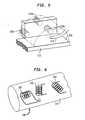
- the system illustrated schematically in Figs. 5 and 6is similar to that discussed above, except that the roles of the transmitter and sensors are reversed. That is, the probe or object 114 to be tracked is equipped with a transmitters 118 incorporating three miniature coils 120, 122 and 124 disposed on mutually orthogonal axes. These are linked to a control system and coil drivers (not shown) similar to those discussed above with reference to Fig. 3 .
- the fixed reference frame systemhas three undirectional sensors 110a, 110b and 110c mounted in fixed position relative to the patient receiving bed 112. The sensors are mounted in a common plane. The common plane of the sensors extends generally vertically on one side of the patient receiving bed. The sensing volume 150 extends outwardly from the common plane of the sensors, above the patient receiving bed.
- This systemcan be used in essentially the same manner as the system discussed above.
- the current delivered to each coil, and hence the dipole moment of the transmitted field associated with each coilis adjusted so that the magnitude of the field component in the sensing direction of each sensor prevailing at each sensor is within a preselected range of magnitudes.
- the transmitting coils 10 of Fig. 1can be disposed in a vertical plane arrangement as illustrated for the sensors in Fig. 5 .
- the number of transmitters and sensorscan be varied.
- the systemmay include a sensor having three mutually orthogonal sensing axes and a set of three mutually orthogonal transmitting coils having a common center in the fixed frame of reference.
- the systemmay include a single uniaxial transmitting coil on the object to be located and three sets of sensors on the affixed frame of reference, each such sensor set incorporating three receiving coils or component sensors adapted to detect fields in a mutually orthogonal direction.
- the reciprocal arrangementwith three sets of mutually orthogonal transmitting coils and a single uniaxial sensor on the object to be tracked --is also usable.
- the sensors and transmittersshould define a plurality of transmitter-receiver pairs, each including one element on the object and one element on the fixed frame of reference.
- the systemadjusts the output of the transmitters in response to the calculated disposition of the object being tracked, rather than directly in response to the component signals or total field magnitude signal.
- the systemcan initially operate with the default of current values; derive an initial reading of the position and orientation of the object and then use that initially determined position and orientation to calculate the desired setting for each coil to achieve the desired field levels at the sensor. Such desired setting is selected to yield the field within the desired magnitude range at the object, assuming that the object has the position and orientation found in the initial reading.
- the so-calculated coil currentsare utilized and the process is repeated.
- the systemcan store a lookup table listing the appropriate coil currents for various combinations of object position and orientation. Using the initially determined position and orientation, the system retrieves appropriate coil-current values from the lookup table for use in the next cycle.
- the senoris associated with a catheter.
- the same systemcan be used with other medical instruments as, for example, endoscopes and surgical instruments.
- the systemcan also be applied to determine the disposition of objects other than medical instruments. For example, it can be used in tracking an input device for a computer.
- the inventioncan be applied in the medical and surgical fields as well as in the health care industry.
- Appendix ACalculation of Position and Orientation
- the magnetic field detected by a sensoris a function of the position and orientation of the sensor.
- field generator coilsare stimulated sequentially.
- [sensor]designates a particular sensor and [coil] designates a particular transmitter coil.
- e le l ⁇ 11 e l ⁇ 12 e l ⁇ 13 e l ⁇ 21 e l ⁇ 22 e l ⁇ 23 e l ⁇ 31 e l ⁇ 32 e l ⁇ 33
- e pe p ⁇ 11 e p ⁇ 12 e p ⁇ 13 e p ⁇ 21 e p ⁇ 22 e p ⁇ 23 e p ⁇ 31 e p ⁇ 32 p ⁇ 33
- e ne n ⁇ 11 e n ⁇ 12 e n ⁇ 13 e n ⁇ 21 e n ⁇ 22 e n ⁇ 23
- the theoretical magnetic field for an orthogonal system generated at sensor position pointing to e l [i] directioncan be expressed as: f coil ⁇ i ⁇ x y z ⁇ ⁇ ⁇ (detail abbreviated), where f is a known function, and includes a dipole moment term having magnitude proportional to the current flow in the particular coil.
- a well-known non-linear least squares equation solvercan be applied to solve the above equations and find probe position x, y, z and orientation ⁇ , ⁇ , ⁇ .
- Appendix BRegistration of Fiducial Markers
- the registration procedureis to find rotation angles ⁇ , ⁇ , ⁇ and space translation x, y, z by solving the above 9 equations.
- the rotation matrix R and translation matrix Tcan be applied to subsequent positions obtained, including the positions of the of the sensor associated with the catheter.
Landscapes
- Life Sciences & Earth Sciences (AREA)
- Health & Medical Sciences (AREA)
- Engineering & Computer Science (AREA)
- Physics & Mathematics (AREA)
- Animal Behavior & Ethology (AREA)
- General Health & Medical Sciences (AREA)
- Pathology (AREA)
- Biomedical Technology (AREA)
- Heart & Thoracic Surgery (AREA)
- Medical Informatics (AREA)
- Molecular Biology (AREA)
- Surgery (AREA)
- Human Computer Interaction (AREA)
- Biophysics (AREA)
- Public Health (AREA)
- Veterinary Medicine (AREA)
- General Physics & Mathematics (AREA)
- Measurement Of Length, Angles, Or The Like Using Electric Or Magnetic Means (AREA)
- Feedback Control In General (AREA)
- Geophysics And Detection Of Objects (AREA)
- Endoscopes (AREA)
- Arrangements For Transmission Of Measured Signals (AREA)
- Radar Systems Or Details Thereof (AREA)
- Near-Field Transmission Systems (AREA)
Abstract
Description
- The present invention relates to systems for determining the location and/or orientation of objects in space by detecting magnetic fields.
- Various systems have been proposed for detecting the position and/or orientation of an object using magnetic or electromagnetic fields. These systems typically employ field transmitters, such as electromagnet coils, disposed at known locations in a fixed reference frame and a sensor, such as a coil or other transducer mounted to the object to be located. Each transmitter projects a field varying in space in a fixed frame of reference. The pattern of variation in space for each transmitter is different than the pattern for each other transmitter. For example the transmitters may be identical to one another but disposed at different locations or in different orientations. The field patterns of the transmitters are thus displaced or rotated relative to one another and relative to the fixed frame of reference. The sensor on the object detects the parameters of the field prevailing at the location of the object as, for example, the magnitude and/or direction of the field at the object or the magnitudes of individual components of the field at the object in one or more preselected directions. The transmitters may be actuated in a predetermined sequence so that at any time only one transmitter is active and therefore the field prevailing at the object is only the field contributed by one transmitter, plus a background field due to the Earth's magnetic field and other environmental sources. Alternatively, the transmitters can be driven at different frequencies so that components of the signal from the sensor varying at different frequencies represent contributions to the field at the object from different transmitters. Based upon the detected parameters of the fields from the individual transmitters, and the known pattern of variation of the field from each transmitter, a computer system calculates the position and orientation of the sensor, and hence the position of the object bearing the sensor, in the fixed frame of reference of the transmitters. In a variant of this system, the object to be located carries the transmitter or transmitters, whereas a plurality of sensors are disposed at various locations or orientations in the fixed frame of reference. The location and/or orientation of the object is deduced from signals representing the parameters of the field prevailing at the various sensors.
- Systems of this general nature are disclosed in United States Patents
4,849,692 ;4,642,786 ;4,710,708 ;4,613,866 and4,945,305 . Systems according to this general design can be used to provide a three-dimensional spatial input capability for a computer. Another system of this nature is disclosed in International Patent publicationWO94/04938 5,042,486 ;5,099,845 ;5,211,165 ;5,251,635 ;5,253,647 ;5,255,680 ;5,265,610 and5,391,199 . - Systems of this nature typically have used fields having strength which varies as the third power, or a higher power, of distance from the transmitter. There is, accordingly, a very large variation in the strength of each field from location to location. In a medical device locating system, adapted to detect the location of the sensor anywhere within a sensing volume having dimensions on the order of 0.5 to 1.0 m, the field strength may vary through many orders of magnitude from one end of the sensing volume to another. When the sensor and the object to be located happen to be near a particular transmitter, they will receive an extremely strong field, whereas when the sensor and object are at the end of the sensing volume remote from the particular transmitter, they will receive only a very weak field from that transmitter. This requires a sensor with a very substantial dynamic range, capable of accurately monitoring very strong and very weak fields. That, in turn, poses stringent demands on the design of the sensor and may require a larger sensor. Moreover, the signal to noise ratio is poor when monitoring a very weak field and the accuracy of the system is accordingly less than optimum in these conditions. Both of these considerations are particularly important in systems for medical applications, where the sensor must be small to fit inside a medical device such as a catheter or endoscope. Although such systems can provide useful results, further improvement would be desirable. The same problems arise in systems using a coil or other transmitter on the object to be located and plural sensors in the fixed frame of reference. Here again, a particular sensor will be exposed either to a very strong field or a very weak field depending on whether the transmitter is adjacent to or remote from the sensor in question.
- Commonly assigned, United States Patent
5,558,091 discloses a solution to these problems. Certain preferred embodiments according to the '091 patent include electromagnets which are operable to generate a plurality of different magnetic fields. Each field has at least one component with a non-zero magnitude that is either constant, linear or nearly linear with respect to distance in a particular direction within a sensing volume. Such an arrangement provides less variation in field magnitude throughout the sensing volume than a comparable arrangement in which the field strength varies as the third or higher power of distance. Thus, with the quasi-linear fields, the difference between minimum and maximum field within a given sensing volume is substantially smaller. This substantially alleviates the problems discussed above. However, it is not always convenient to use the particular coil arrangements which provide such quasi-linearly varying fields. US 4,652,820 discloses a combined magnetic sensor and actuator device for applying a magnetic force to a magnetizable body and for sensing the distance between the device and the magnetizable body. The apparatus includes a low frequency electric current source, a high electric current source, a detector and a magnetizable pole piece which interacts with a body provided on a shaft. The low frequency current source provides an actuating signal which maintains the shaft at a desired position or moves it in a desired manner. High frequency current source and detector are utilized to detect the position of the shaft.WO 92/05543 - One aspect of the present invention provides apparatus for determining position including field generating means for producing a plurality of magnetic fields. The field generating means is arranged to provide such fields having parameters, such as field strength and/or field direction, varying with location within a sensing volume according to known patterns of variation. The pattern of variation for each field is different than the pattern of variation for each other field. For example, where the field generating means includes a plurality of transmitting coils, the coils are disposed at different locations and/or different orientations relative to the sensing volume. Apparatus according to this aspect of the invention also includes at least one sensor adapted to detect one or more parameters of the field prevailing at the sensor when the sensor is at an unknown location within the sensing volume, and to provide one or more sensor signals representing such detected parameters. For example, the sensor may include a sensor body and a plurality of component sensors disposed on the sensor body, each component sensor being operative to measure the magnitude of a magnetic field component in a preselected local direction relative to the sensor body to provide a component sensor signal representing that particular component of the field prevailing at the sensor. The apparatus further includes calculation means for calculating the location of the sensor, the orientation of the sensor or both based upon the sensor signals and upon the unknown patterns of variation of the fields. The apparatus also includes feedback control means for adjusting the field generating means to alter the known pattern of variation of at least one of the fields responsive to the sensor signals, to the calculated location of the sensor or both so as to maintain the detected parameters of the altered field at the sensor within a preselected range. For example, where the field generating means includes a plurality of transmitters disposed adjacent the sensing volume, the feedback control means can be arranged to increase the strength of the field transmitted by a particular transmitter when the sensor is remote from such transmitter, and to decrease the strength of the field emitted by that transmitter when the sensor is close to the transmitter. Thus, the parameters of the field detected at the location of the sensor will always lie within a relatively narrow range of values. Because the transmitted field is altered in a known manner, the position and/or orientation of the sensor can still be calculated, simply by using the altered field as the basis for calculation. For example, where the feedback control means increases the current flowing to an electromagnetic coil, the parameters used in the calculation to represent the strength of the field emitted from that particular coil are adjusted accordingly.
- Apparatus according to this aspect of the present invention can maintain the detected field parameters at the sensor location, such as the magnitude of the field at such location, within a relatively narrow range even where the field strength varies with a power of distance greater than the first power as, for example, where the field strength varies with the third power of distance from the coil. The system therefore can provide good signal to noise ratio, even with a very small sensor. Moreover, there is no need for any particular coil configuration to produce a linear or quasi-linear field. For example, in a medical application, a plurality of individual coils may be disclosed at various locations beneath a patient receiving bed, or on one side of the bed.
- Although apparatus according to this aspect of the invention can utilize any type of sensor, it has additional advantages when used with magnetoresistive sensors or other sensors which can lose accuracy when exposed to very high magnetic fields. Because the field is maintained within a relatively narrow range, the sensors are not exposed to fields which would impair their accuracy. In a further variant of the invention, the feedback control system is actuated to maintain the parameters of the field at each sensor within the narrowest attainable range of values. Thus, the feedback control maintains the field parameters at the sensor at substantially constant values. Here again, the transmitted fields are altered in a known manner, and the disposition of the sensor can still be calculated by using the altered fields as the basis for calculation.
- A further aspect of the present invention (not claimed) provides apparatus including at least one transmitter adapted for mounting to the object to be located and also including a plurality of sensors disposed adjacent a sensing volume. The apparatus according to this aspect of the invention includes calculation means for determining a calculated location of the transmitter based upon signals from the sensors and upon the known pattern of variation of the field at the transmitter. Here again, feedback control means are provided for adjusting the field generating means to alter the known pattern of variation of field sent by the at least one transmitter in response to the sensor signal, to the calculated location of the transmitter or both so as to maintain the parameters of the field from the at least one transmitter prevailing at each sensor within a preselected range. This arrangement is similar to the arrangement discussed above, except that the transmitter or transmitters are disposed on the object to be located whereas the sensors are located in the fixed frame of reference of the sensing volume. Here again, when the transmitter is close to the sensor, or where the orientations of the transmitter and sensor favor strong coupling between the transmitted field and the sensor, the strength of the field is reduced. If the transmitter is relatively far from the sensor, or in a unfavorable orientation, the control means increases the strength of the transmitted field. This arrangement provides advantages similar to those discussed above.
- A further aspect of the invention (not claimed) provides apparatus for sensing the disposition of an object--its position, orientation or both--in a frame of reference. Apparatus according to this aspect of the invention includes transmitter means including at least one transmitter for providing a field and sensor means including at least one sensor for sensing one or more parameters of a field prevailing at each such sensor and providing one or more sensor signals indicative of such parameters. The transmitter means and said sensor means cooperatively define a plurality of transmitter-sensor pairs, each including one transmitter and one sensor as elements of the pair, one element of each such pair being disposed on the object and the other element of each such pair being disposed at a known disposition in said frame of reference. Typically, at least one element of each transmitter-sensor pair is disposed at a different position or orientation than the corresponding element of the other pairs. The apparatus further includes calculation means for determining the disposition of said object based upon said sensor signals feedback control means for adjusting said transmitting means responsive to said sensor signals to thereby maintain at least one of said sensor signals within a preselected range.
- Further aspects of the present invention provide methods of determining position and/or orientation wherein the operation of field generating means is altered by feedback control based upon the signals from the sensor, or from the calculated location of the sensor of the transmitter, to maintain the parameters of each field to be detected by each sensor within a preselected range.
- Other objects, features and advantages of the present invention will be more readily apparent from the detailed description of the preferred embodiments set forth below, taken in conjunction with the accompanying drawings.
Figure 1 is a diagrammatic prospective view depicting portions of apparatus in accordance with one embodiment of the invention.Figure 2 is a fragmentary, diagrammatic prospective view depicting a portion of the apparatus illustrated inFig. 1 .Figure 3 is a functional block diagram depicting further portions of the apparatus depicted inFigs. 1 and 2 .Figure 4 is a block diagram depicting certain steps in methods according to embodiments of the invention.Figures 5 and 6 (not claimed) are a diagrammatic perspective view depicting portions of apparatus in accordance with a further embodiment.- Apparatus in accordance with one embodiment of the present invention includes three generally helical transmitter coils 10 disposed in a common plane.
Coils 10 are mounted in fixed position in the frame of reference ofpatient receiving bed 12. That frame of reference is denoted by a Cartesian coordinate system X, Y, Z as shown inFig. 1 . A patient P may be positioned on the patient receiving bed. Theaxes 11 of the coils are parallel to one another. Apatient receiving bed 12 extends just above the plane ofcoil 10. The apparatus further includes an object orprobe 14. The probe is adapted to be inserted into a medical instrument such as acatheter 16 and positioned at a desired location in the catheter, such as at the distal tip of the catheter or at another location along the length of the catheter.Probe 14 has mounted thereon asensor 18.Sensor 18 includes threecomponent sensors component sensor 20 is sensitive to magnetic fields directed in direction X', but largely insensitive to fields in directions Y' and Z', whereassensor 22 is sensitive only to fields in direction Y' andsensor 24 is sensitive to fields in direction Z'. These sensors are adapted to provide separate sensor signals representing the separate components.Sensor 18 may be a solid state sensor of the type described in the aforementioned International Patent PublicationWO95/09562 sensor 18 may include an array of miniature coils, the axes of the coils being oriented orthogonal to one another. Although these represent the preferred sensors, essentially any other magnetically sensitive device may be employed as, for example, magneto-optical sensors and flux gate magnetometers. Component sensors cable 26, with separate leads for each sensor, to acommand unit 28. Command unit 28 (Fig. 3 ) includes an input amplification and analog to digital ("A/D")conversion section 30 adapted to receive the individual signals fromcomponent sensors sensor 18, amplify the same and convert the same to digital form. The amplification and A/D conversion unit 30 may also include other conventional signal processing devices such as analog or digital band pass filtering and noise rejection devices and signal averagers.Command unit 28 further includes acomputation unit 32.Computation unit 32 may be implemented as a programmed general purpose computer. As further discussed below, the position computation unit is arranged to compute the disposition ofsensor 18, and hence the disposition of the object or probe 14 at the catheter tip from the sensor signals. As used in this disclosure, the term "disposition" of an element refers to the position of the element, the orientation of the element or both. Thus, the computation unit is arranged to calculate the position ofsensor 18, the orientation of the sensor, or, preferably, both position and orientation.Command unit 28 may be linked to a display device (not shown) for providing a human intelligible representation of the position of the probe orobject 14. Such human intelligible representation may be provided either as numerical information presenting the position and/or orientation ofobject 14 in the X, Y, Z coordinate system or, preferably, as a pictorial representation of the object and of the associated catheter superposed on a pictorial representation of the patient .Command unit 28 further includes acontrol unit 34.Control unit 34 is linked byoutput lines separate coil drivers coil 10. Each coil driver is arranged to control the amplitude of such current, and to turn the current on or off, in response to control signals received fromcontrol unit 34. The control unit is arranged to signal the coil drivers to provide currents to their respective transmit coils in alternating sequence, so thatcoil 10a receives current whilecoils coil 10b receives current whilecoils coil 10c receives current whilecoils conversion section 30 and, as further discussed below, actuates the coil drivers to vary the amplitude of the current to each coil. The control unit may include conventional interface devices such as digital to analog converters or bus interface units so that the output of the control unit is compatible with the control input of each coil driver. Also, although the control unit is illustrated separately from the other logical units ofcommand unit 28, it should be appreciated that the control unit may share physical elements of the command unit and other elements. For example, where the command unit incorporates a general purpose computer, the processor of the computer may serve both as an element of the position computation unit and as an element of the control unit, executing functions appropriate to the different units at different times.- In a method according to one aspect of the invention, an
catheter 16 is advanced into the body of a patient P. Theprobe 14 withsensor 18 thereon is disposed at the tip of the catheter. The catheter tip is disposed at an unknown location somewhere above the plane ofcoils 10.Control unit 34 actuates the coil drivers in sequence, using an initial or default value for the current amplitude to be provided to eachcoil 10. Amplification andconversion unit 30 samples the signal from each of thecomponent sensors coil 10a,unit 30 takes a sample of the signal from each ofcomponent sensors Command unit 28 then calculates a total field magnitude based upon these individual signals. The total field magnitude is:
where: - B10a is the magnitude of the magnetic field vector at
sensor 18 at the time thatcoil 10a is actuated; - K20 is a sensitivity factor relating the signal strength from
sensor 20 to the magnetic field component along axis X'; - S20 is the signal strength from
sensor 20 during the actuation; and - K22, S22 and K24 and S24 are similar sensitivity constants and signal strengths for the
other sensors - In like manner, the system actuates
coils coil 10b and independently computes the magnitude of the total field vector prevailing at the sensor during actuation ofcoil 10c. - As shown in
Fig. 4 , after detecting the component signals and calculating the total field magnitude prevailing at the sensor during actuation of each coil, the control unit determines whether or not all of the field magnitudes are within a preselected range of magnitudes. This preselected range is chosen to lie within the optimum operating range ofsensor 18. Thus, the minimum field magnitude is selected to lie well above the noise threshold of the system and above the minimum sensitivity level of the sensor, where the maximum field level is selected to lie well below the maximum limit of linearity of the sensor, and well below the maximum field which the sensor can tolerate without loss of accuracy. For a typical magneto-resistive sensor, which is most accurate and repeatable when used with fields of less than about 4 Gauss, the preselected range of field magnitudes may be from about 1.0 to about 2.5 Gauss. With typical Hall effect sensors, which are most accurate when used with fields over about 30 Gauss, the preselected range will be above about 30 Gauss. If the three field vector magnitudes observed during actuation of the threeunits sensor 18, and hence the position and orientation ofprobe 14 and the associatedtip 16 of the catheter using conventional position finding algorithms. For example, the mathematical methods disclosed in United States Patent4,710,708 for finding positions using a multiple transmitting or receiving stations and a multi-axis sensor can be employed. Briefly, the magnitude of the fields in each of the local or sensor directions X', Y', Z' represented by each of the component sensor signals from each of thecomponent sensors probe 14 and of the distal tip of the catheter. - If one or more of the field magnitudes is out of the preselected range, the system does not calculate the position and orientation. Instead, control
unit 34 changes the field strength of the coil or coils associated with the out-of-range field strength. For example, whereprobe 14 andsensor 18 are relatively close tocoil 10a, the total field magnitude detected whencoil 10a is actuated will be above the preselected range.Control unit 34 therefore will commandcoil driver 42 to reduce the current tocoil 10a on the next actuation cycle. Conversely, if the probe and sensor are relatively far fromcoil 10c, the field magnitude sensed during actuation ofcoil 10c with the default of current value will be below the preselected range.Control unit 34 therefore will instructcoil driver 46 to increase the current tocoil 10c on the next actuation cycle. The coil drivers may be arranged to vary the overall field strength or dipole moment of each coil stepwise, as by varying the current stepwise. Each increase or decrease commanded bycontrol unit 34 may be one step. Alternatively, the control unit can calculate an increase or decrease proportional to the degree to which the total field magnitude deviates from a target value within the preselected range. Thus, a relatively large change can be made when the field magnitude is far outside of the range, whereas a smaller change can be employed when the field magnitude is close to the range or within the range. The correction process continues until all field strengths are within the preselected range, whereupon the system calculates position and orientation. After the system finds values of coil currents which produce field magnitudes within the range, subsequent actuation cycles use these currents. During operation, as the physician utilizescatheter 16, the position of the catheter tip, and hence the position ofprobe 14 andsensor 18 may change. Any such change may bring one or more of the field magnitudes outside of the preselected range, whereupon the system will readjust the currents to the coils once again. - As the feedback control unit readjusts the currents to the coils, the altered values of current are translated into new values for field strengths from the individual coils which are used in the aforementioned position determining equations. In this manner, the system assures that the sensor is always exposed to a field having a magnitude within the preselected range wherever the sensor is placed within a
sensing volume 50 extending over a preselected region above the plane ofcoils 10. The exact size ofsensing volume 50 will depend upon the breadth of the preselected field magnitude range and the dynamic range ofcoil drivers sensing volume 50 within which the sensor will receive fields within the preselected field magnitude range from all coils will also depend upon the positions of the coils. However, for a typical system having three coils spaced at vertices of an equilateral triangle with sides about 40 cm long, the sensing volume includes a region extending upwardly about 60 cm from the plane of the coils. At the plane of the coils, the sensing volume extends about 20 cm beyond the equilateral triangle bounded by the coils. - In the description set forth above, only one sensor is employed to determine the position and location of only one object. However, plural objects and plural sensors may be utilized. As described in the aforementioned International Publication
WO95/09562 sensor body 52, atag 53 and a sensor 54 of the same type assensor 18 releasably connected to the sensor body. The amplification andconverson unit 30 is connected to each of these additional sensors in the same manner as tosensor 18. The tag of each sensor may be affixed to the body of the patient, and an image of the patient may be acquired using any imaging method which will show the desired structures of the patient's body and which will also show thetags 53 as, for example, magnetic resonance imaging (MRI), X-ray, CAT scanning or the like. Thus, the tags are constructed to facilitate imaging in the desired imaging method. Where X-ray imaging is used, the tag may be radioopaque; where MRI imaging is used, the tag may include a material which has magnetic resonance response readily distinguishable from that of bodily tissue. Ordinarily, the image is acquired prior to use of the catheter and probe discussed above. The sensors 54 typically are not present in the imaging step. After the imaging step, the sensor bodies 54 and sensors of the fiducial markers are attached to the patient's body at the positions of the tags. When the catheter is employed, sensor signals fromsensor 18 on the probe in the catheter are acquired concurrently with signals from thesensor 52 on the fiducial markers. The system determines the location and orientation of sensor 54, and hence offiducial markers 52 using magnetic fields fromcoils 10 in the same manner as the system determines the position and orientation ofsensor 18 andprobe 14. The acquired position and orientation of thefiducial markers 52 can be used to register the previously acquired image of the patient with the position and orientation data forsensor 18 andprobe 14. For example, where the position and orientation data for thesensor 18 andprobe 14 are displayed as a pictorial image of thecatheter tip 16 on a screen, the position and orientation of fiducial markers, as determined by the magnetic field locating method can also be displayed. The previously acquired image data may be displayed as a pictorial representation of the patient's structures and that representation will also include a picture of thetags 53. The previously acquired images of the tags are brought into registration with the images of the fiducial markers derived from magnetic location by transforming one or the other image until the picture of the tags in the previously acquired image overlies the representation of the fiducial marker in the magnetically acquired image. Such registration can be achieved by manually adjusting inputs to an image display system while visually matching the displayed images, as described in the aforementioned '562 International Publication. or else by automatic calculation of the transformation and rotation parameters necessary to bring the images into registration. Such parameters can be calculated by equating the positions of three or more fiducial marker sensors in the magnetic location frame of reference (the X,Y,Z coordinates ofFig. 1 ) with the positions of thetags 53 in the image frame of reference as modified by a matrix of unknown rotations a further matrix of unknown transformations. As further described in Appendix B, the resulting matrix equation yields an overdetermined system of nonlinear equations which include the rotation angles and transformation distances. When the images are properly registered, the position of the catheter tip is displayed in true location and orientation relative to the patient's internal structures. In similar fashion, a greater number of fiducial markers, or more than one medical instrument may be located. - In a system using multiple sensors, such as
sensors 18 and 54, the coils may be operated in separate cycles so as to provide each sensor with fields having magnitudes in the preselected range appropriate for the sensor. For example,control unit 34 may actuate thecoil drivers sensor 18 are acquired and the signals from sensors 54 of the fiducial markers are ignored. During the first cycle, the coil currently is adjusted to yield field magnitudes atsensor 18 within the preselected range as discussed above. During the second cycle, the signals from thesensor 54a of a first fiducial marker are acquired, the signals fromsensor 18 and the otherfiducial marker sensors sensor 54a within its preselected range. In the third cycle, the signals fromsensor 54b are acquired whereas the other signals are ignore; in the fourth cycle, the signals fromsensor 54c are acquired and others are ignored. The cycles may be sequential, with the entirety of a first cycle being performed before the entirety of a second cycle. The cycles may also be interspersed with one another. For example,coil driver 42 can be actuated first to provide a current appropriate to yield the proper field at thefirst sensor 18 and then can be actuated to provide the appropriate fields at thefiducial marker sensors - Certain sensors tend to lose accuracy when exposed to magnetic fields above a predetermined maximum. For example, certain magneto-resistive sensors temporarily lose accuracy if exposed to magnetic fields above about 4 Gauss. Where such sensors are employed in a multi-sensor system, the system should have appropriate provisions to avoid exposing sensors to excessive fields. For example, if
sensor 54a is disposed close tocoil 10b, whereassensor 18 is disposed remote fromcoil 10b,sensor 54a may be exposed to extremely high field levels if the system adjusts the current incoil 10b to the level required to generate the appropriate field atsensor 18. To avoid this condition, the data from all sensors can be acquired during all of the cycles, andcontrol unit 34 can be arranged to increase coil currents in a progressive manner over several cycles when an increase is required. The data from sensors which are not used for position monitoring on a particular cycle can be used to inhibit further increases if the field at the nominally unused sensor is approaching dangerous levels. Thus, if the system is in the process of progressively increasing the coil current incoil 10b to provide an adequate field level atsensor 18, the system may terminate such increases if the field magnitude atsecond sensor 54a during the reading cycle associated withfirst sensor 18 reaches the maximum level allowed at the second sensor. If this condition occurs while the field level atfirst sensor 18 is still below the preselected range, the system may display an error message or else may attempt to calculate position and orientation based on out-of-range sensor signal, or both. Alternatively, if the accuracy of the sensor can be restored, the data from the nominally unused sensors can be used to initiate restoration. For example, certain magnetoresistive sensors use a biasing magnetic field. If exposed to excessive fields, such sensors can be reset and restored to accuracy after the excess field is removed by adjusting a bias magnetic field applied within the sensor. The command unit may be arranged to trigger the reset process for one sensor if it is exposed to excess field during a cycle associated with another sensor. - In the foregoing discussion, the coils are driven alternately in a time-multiplexed arrangement. Frequency domain multiplexing can also be employed. Thus, each coil can be actuated with a driving current having a different carrier frequency, and such actuation can be substantially continuous. The signals from
sensor 18 will include components varying at the different carrier frequencies, which can be segregated by analog or digital filtering methods. Thus, the signals fromcomponent sensor coil 10a can be used to calculate the total field magnitude attributable tocoil 10a. That value in turn can be used to triggerfeedback control unit 34 to adjust the current tocoil 10a. The currents in the other coils can be adjusted in similar manner using the components varying at their respective carrier frequencies. The frequency division multiplexing approach can be extended to multiple sensors. For example, each coil can be driven at a multiple carrier frequencies, equal to the number of sensors, the carrier frequencies for each coil being different from one another and different from all of the other carrier frequencies for all of the other coils. The components in the signals from the first sensor varying at the respective first carrier frequencies can be detected and the strength of the coil currents at the respective first carrier frequencies can be adjusted accordingly, so that the field magnitudes at the first carrier frequencies prevailing atsensor 18 will be within the desired range. In this stage of the process, the components varying at the other carrier frequencies are ignored. The process is reversed with respect thefiducial marker sensor 54a. This approach can be extended to greater numbers of sensors. Also, the frequency multiplexing and time multiplexing approaches can be combined. Thus, each coil can be driven at only one carrier frequency. During a first cycle,first sensor 18 is actuated and the components varying at all of the carrier frequencies are monitored. The coil currents are adjusted accordingly to bring the fields at each carrier frequency into the desired range. During a second cycle, thesecond sensor 54a (the first fiducial marker sensor) is used and the coil currents are adjusted in the same manner, and so on with the other fiducial marker sensors. - In a further variant, the coil currents, and hence the strengths of the fields from the individual transmitters, can be adjusted to bring the field components detected by each individual component sensor to within a preselected range. In such a system, each coil is adjusted separately with respect to each component sensor. In a first cycle, the current to transmit
coil 10a is adjusted to bring the individual sensor signal fromcomponent sensor 20, representing the field component magnitude in the local X' direction, into a preselected range. During this cycle, the signals from theother component sensors coil 10a is readjusted to bring the field component in the wide prime direction into a preselected range and thus bring the signal from Y primedirection component sensor 22 into the optimum range. Thesame coil 10a then brings the field component in local direction Z' into a preselected range, and the signal from the primedirection component section 24 is monitored. This sequence of operations is then repeated again for each of the other transmitter coils. This approach can be extended to plural sensors, each having plural component sensors. Here again, the system keeps track of the coil current magnitudes used to produce the fields since by each component sensor. The coil current is reflected in the coil dipole moment (overall field strength) terms of the simultaneous equations. - Where the local direction associated with a particular component sensor is orthogonal, or nearly orthogonal, to the direction of the field produced by a particular coil at the sensor, it may be impossible to bring the component in that local direction into the preselected range without either exceeding the current capacity of the coil driver or producing a total field so strong as to impair one of the other sensors. In this instance, however, at least one of the other component sensors will receive a component having a magnitude in the preselected range of magnitudes. In this variant, the signal from all of the component sensors may be monitored during a cycle associated with a particular component sensor. The maximum current applied to the coil may be limited to avoid exposing any other unused component sensor to an excessive field component in its sensing direction.
- In a further variant of this approach, the preselected range of magnitudes for the field component in any particular direction is narrowed to include only a single preselected value, preferably within the optimum range of accuracy of the particular component sensor. The feedback control system thus operates to adjust the coil currents until the field component magnitude is at such single value. The position and orientation are calculated in the same way as discussed above. This variant has the advantage that nonlinearity in the component sensor response cannot affect the accuracy of the system. Provided that it is known that a particular reading from the sensor corresponds to the preselected value of field component magnitude, deviation from a linear relationship between component magnitude and sensor reading at other values of the component magnitude will not impair the accuracy of the system.
- Certain field sensors exhibit so-called "off-axis sensitivity". That is, the transfer function or relationship between field component magnitude along the sensitive axis of a particular component sensor and the reading from that component sensor varies when a strong field component orthogonal to such axis is present. Off-axis sensitivity can be corrected by using the readings from two component sensors to evaluate the magnitude of the field perpendicular to the sensitive axis of the third component sensor, and using that magnitude to determine a correction factor to be applied to the reading from the third component sensor.
- In the system described above, when the coils are driven with direct current, amplification and
conversion unit 30 samples the data from each component sensor at a preselected delay time after the inception of the current. In a variant of this system, the command unit adjusts the delay time from inception of the current to sampling depending upon the current applied in a particular actuation. After inception of the current, the current gradually rises to its steady state value, and hence the overall field strength or dipole moment likewise rises gradually. The changing field induces eddy currents in electrically conductive materials which may be present in or near the sensing volume. These currents induce additional magnetic fields, which can induce erroneous sensor readings. The eddy currents decay when the rate of change in the field slows, as the field approaches its steady state value. The delay time should be long enough for the current to rise to an appreciable portion of its steady state value, and long enough for eddy currents to dissipate sufficiently that they do not cause appreciable errors. The required delay time is less with smaller field magnitudes. - The system illustrated schematically in
Figs. 5 and 6 is similar to that discussed above, except that the roles of the transmitter and sensors are reversed. That is, the probe or object 114 to be tracked is equipped with atransmitters 118 incorporating threeminiature coils Fig. 3 . The fixed reference frame system has threeundirectional sensors patient receiving bed 112. The sensors are mounted in a common plane. The common plane of the sensors extends generally vertically on one side of the patient receiving bed. Thesensing volume 150 extends outwardly from the common plane of the sensors, above the patient receiving bed. - This system can be used in essentially the same manner as the system discussed above. Here again, the current delivered to each coil, and hence the dipole moment of the transmitted field associated with each coil is adjusted so that the magnitude of the field component in the sensing direction of each sensor prevailing at each sensor is within a preselected range of magnitudes.
- Numerous combinations and variations of the features discussed above can be utilized without departing from the present invention. By way of example, the transmitting coils 10 of
Fig. 1 can be disposed in a vertical plane arrangement as illustrated for the sensors inFig. 5 . Also, the number of transmitters and sensors can be varied. For example, as disclosed in the aforementioned International PublicationWO94/04938 - In a further variant, the system adjusts the output of the transmitters in response to the calculated disposition of the object being tracked, rather than directly in response to the component signals or total field magnitude signal. Thus, the system can initially operate with the default of current values; derive an initial reading of the position and orientation of the object and then use that initially determined position and orientation to calculate the desired setting for each coil to achieve the desired field levels at the sensor. Such desired setting is selected to yield the field within the desired magnitude range at the object, assuming that the object has the position and orientation found in the initial reading. On the next cycle, the so-calculated coil currents are utilized and the process is repeated. In a variant of this approach, the system can store a lookup table listing the appropriate coil currents for various combinations of object position and orientation. Using the initially determined position and orientation, the system retrieves appropriate coil-current values from the lookup table for use in the next cycle.
- In the embodiments discussed above, the sensor is associated with a catheter. The same system can be used with other medical instruments as, for example, endoscopes and surgical instruments. The system can also be applied to determine the disposition of objects other than medical instruments. For example, it can be used in tracking an input device for a computer.
- As these and other variations and combinations of the features described above can be utilized without departing from the invention, the foregoing description of the preferred embodiments should be taken by way of illustration rather than by way of limitation of the invention as defined by the claims.
- The invention can be applied in the medical and surgical fields as well as in the health care industry.
- Provided that we know the physical configuration of the field generator (transmitter) which is fixed in position during operation, the magnetic field detected by a sensor is a function of the position and orientation of the sensor. In our system field generator coils are stimulated sequentially. The field sensed by a sensor (3 component sensors per probe) can be expressed in terms of position in x, y, z and orientation α, β, γ (roll, pitch and yaw respectively) i.e.:

- Where [sensor] designates a particular sensor and [coil] designates a particular transmitter coil.
- If the real field the sensor measures when [coil] is on is B'[sensor][coil], then theoretically,

i.e.
- Since we have 3 sensors and 3 coils, the total equations are 9 with 6 unknowns (x, y, z for probe space location, α, β, γ for its orientation). By applying non-linear least square method, we can find unique x, y, z, α, β, γ for the probe.
- Above shows the general ideal of the algorithm. In detail:
- Assume the orthogonal X,Y,Z reference coordinate system (magnetic location Cartesian coordinate) is described by matrix

the probe's orthogonal system is:
and, since the three sensors on probe may not be orthogonal to each other, their non-orthogonal axes can described as:
a transfer matrix T[i][j] which is to be used in later on calculation can be obtained from:
∀i,j ∈ {1,2,3}
another matrix ortho_OV[i][j] which is to be used also can be defined as:
since we use roll(α), pitch(β), yaw(γ) to define probe orientation, ortho_OV[i][j] can be also described by:


orthogonal vector matrix can therefore be calculated by matrix multiplication of previous defined matrix T and orhto_OV:
- The theoretical magnetic field for an orthogonal system generated at sensor position pointing toel
[i] direction can be expressed as:
(detail abbreviated), wheref is a known function, and includes a dipole moment term having magnitude proportional to the current flow in the particular coil. - After non_orthogonality correction (sensors may not be perpendicular to each other), the magnetic field sensor measures should be:

- Assume the real field sensor detected when coil is on isB'[sensor][coil], then:

therefore, the 9 equations to be solved for x, y, z, α, β, γ, are:


- A well-known non-linear least squares equation solver can be applied to solve the above equations and find probe position x, y, z and orientation α, β, γ.
- We know the coordinates of three fiducial points in image data (MR etc.) coordinate system (image position):
- {(Mx1, My1, Mz1), (Mx2, My2, Mz2), (Mx3, My3, Mz3)}
- and the coordinates of the same three fiducal points in the X,Y,Z, coordinate system of the fixed frame of reference of the magnetic locating apparatus:
- {(Px1, Py1, Pz1), (Px2, Py2, Pz2), (Px3, Py3, Pz3)}
- fiducial points {(x1, y1, z1), (x2, y2, z2), (x3, y3, z3)} can be formed by {(a1, b1, c1), (a2, b2, c2), (a3, b3, c3)} through rotation R and translation T. The rotation matrix R is:

where - The translation matrix T is:

- The relationship between image position and magnetic location apparatus frame of reference position is:

or
- This forms 9 single equations:

with 6 unknowns: α, β, γ for rotation angles, x, y, z for space translation. - The registration procedure is to find rotation angles α, β, γ and space translation x, y, z by solving the above 9 equations.
- In pseudo-code, the registration procedure is:

- The rotation matrix R and translation matrix T can be applied to subsequent positions obtained, including the positions of the of the sensor associated with the catheter.


Claims (17)
- Apparatus for determining position comprising:(a) field generating means (10) for producing a plurality of magnetic fields, each said field having parameters varying with location within a sensing volume (50) according to a known pattern of variation, said patterns of variation being different for different ones of said fields;(b) at least one sensor (18) adapted to detect one or more of said parameters of said fields generated by said field generating means prevailing at such sensor when said sensor is at an unknown location within said sensing volume and to provide one or more sensor signals representing said one or more parameters;(c) calculation means (32) for determining a calculated location of said sensor based upon said sensor signals and said known patterns of variation; and(d) feedback control means (34) for adjusting said field generating means to alter said known pattern of variation of at least one of said fields responsive to said sensor signals, said calculated location, or both, so as to maintain said parameters of each such altered field prevailing at said sensor within a preselected range.
- Apparatus as claimed in claim 1 wherein said field generating means is operative to provide DC magnetic fields within said sensing volume.
- Apparatus as claimed in claim 2 wherein said field generating means includes a plurality of coils (10, 120, 122, 124) and means for intermittently actuating each said coil (34, 42, 44, 46) with a direct current, said feedback control means includes means for altering the magnitude of each said direct current, and wherein said calculation means includes means for sampling the signals from each sensor when a delay time has elapsed after commencement of each said intermittent actuation, said feedback control means further including means for varying the delay time for each actuation in accordance with the magnitude of the current applied in such actuation so as to reduce the delay time when lesser currents are employed and increase the delay time when greater currents are employed.
- Apparatus as claimed in claim 1 wherein said field generating means is operative to provide AC magnetic fields within said sensing volume.
- Apparatus as claimed in claim 1 wherein each said sensor has maximum accuracy within a preselected optimum operational range for each said parameter and said preselected range for each said parameter substantially corresponds to said optimum operational range.
- Apparatus as claimed in claim 1 wherein said preselected range for each said parameter consists of a single value, and wherein said feedback control means is operative to maintain each said parameter of the field at each sensor substantially at said single value.
- Apparatus as claimed in claim 1 wherein said field generating means includes a plurality of transmitters (10) disposed adjacent said sensing volume.
- Apparatus as claimed in claim 7 wherein each said transmitter is operative to radiate a field having magnitude decreasing with rn where r is distance from the transmitter and n is a number greater than 1.
- Apparatus as claimed in claim 1 further comprising a sensor body (18), said at least one sensor including a plurality of component sensors (20, 22, 24) disposed on said sensor body, each said component sensor being operative to measure the magnitude of a magnetic field component in a preselected local direction relative to the sensor body.
- Apparatus as claimed in claim 9 wherein said field generating means includes a plurality of transmitters (10) disposed at spaced-apart locations adjacent said sensing volume, said feedback control means being operative to adjust each said transmitter to transmit a plurality of fields so that for each said field, the magnitude of a component of such field in the local direction of one said component sensor will be within a preselected range.
- Apparatus as claimed in claim 10 wherein each said component sensor is a Hall effect sensor, a magnetoresistive sensor, a magnetooptical sensor or a flux gate magnetometer.
- Apparatus as claimed in claim 1 wherein each said sensor includes a coil and wherein said field generating means is arranged to provide AC fields in said sensing volume.
- Apparatus as claimed in claim 1 wherein said field generating means includes a plurality of transmitters disposed at spaced-apart locations on one side of a reference plane and wherein said sensing volume extends to the other side of said reference plane.
- Apparatus as claimed in claim 13 wherein said transmitters are disposed substantially in a common plane.
- Apparatus as claimed in claim 1 wherein said at least one sensor includes a plurality of sensors, and wherein said sensors can be impaired by exposure to fields having components above a predetermined threshold magnitude, and wherein said feedback control means includes means for controlling said field generating means to assure that no sensor is exposed to a field component having magnitude above its threshold value.
- Apparatus as claimed in claim 1 wherein said at least one sensor includes a plurality of sensors and wherein said sensors can be impaired by exposure to fields having components above a predetermined threshold magnitude but can be restored after such exposure upon application of a reset routine, said feedback control means including means for initiating such reset routine in the event of such exposure.
- A method of determining the disposition of an object in a frame of reference comprising the steps of:(a) providing one or more magnetic fields each having a known pattern of variation with respect to said frame of reference;(b) sensing one or more parameters of said one or more magnetic fields prevailing at said object to provide one or more sensor signals indicative of said one or more parameters;(c) calculating the disposition of said object in said frame of reference based upon said sensor signals and said known pattern or patterns of variation; and(d) altering said known pattern of variation of at least one of said one or more magnetic fields responsive to said sensor signals, said calculated disposition, or both, so as to maintain said parameters of each such altered field prevailing at said object within a preselected range.
Applications Claiming Priority (3)
| Application Number | Priority Date | Filing Date | Title |
|---|---|---|---|
| US476380 | 1995-06-07 | ||
| US08/476,380US5729129A (en) | 1995-06-07 | 1995-06-07 | Magnetic location system with feedback adjustment of magnetic field generator |
| PCT/US1996/008411WO1996041119A1 (en) | 1995-06-07 | 1996-06-03 | Magnetic location system with adaptive feedback control |
Publications (3)
| Publication Number | Publication Date |
|---|---|
| EP0830562A1 EP0830562A1 (en) | 1998-03-25 |
| EP0830562A4 EP0830562A4 (en) | 2001-08-22 |
| EP0830562B1true EP0830562B1 (en) | 2009-07-29 |
Family
ID=23891603
Family Applications (1)
| Application Number | Title | Priority Date | Filing Date |
|---|---|---|---|
| EP96917933AExpired - LifetimeEP0830562B1 (en) | 1995-06-07 | 1996-06-03 | Magnetic location system with adaptive feedback control |
Country Status (10)
| Country | Link |
|---|---|
| US (1) | US5729129A (en) |
| EP (1) | EP0830562B1 (en) |
| JP (1) | JP3351796B2 (en) |
| CN (1) | CN1133864C (en) |
| AT (1) | ATE438078T1 (en) |
| AU (1) | AU692398B2 (en) |
| DE (1) | DE69637978D1 (en) |
| DK (1) | DK0830562T3 (en) |
| ES (1) | ES2330060T3 (en) |
| WO (1) | WO1996041119A1 (en) |
Cited By (4)
| Publication number | Priority date | Publication date | Assignee | Title |
|---|---|---|---|---|
| WO2019005699A1 (en)* | 2017-06-28 | 2019-01-03 | Auris Health, Inc. | Electromagnetic field generator alignment |
| US11324558B2 (en) | 2019-09-03 | 2022-05-10 | Auris Health, Inc. | Electromagnetic distortion detection and compensation |
| US12145278B2 (en) | 2017-10-05 | 2024-11-19 | Auris Health, Inc. | Robotic system with indication of boundary for robotic arm |
| US12220189B2 (en) | 2014-10-09 | 2025-02-11 | Auris Health, Inc. | Systems and methods for aligning an elongate member with an access site |
Families Citing this family (438)
| Publication number | Priority date | Publication date | Assignee | Title |
|---|---|---|---|---|
| FR2652928B1 (en) | 1989-10-05 | 1994-07-29 | Diadix Sa | INTERACTIVE LOCAL INTERVENTION SYSTEM WITHIN A AREA OF A NON-HOMOGENEOUS STRUCTURE. |
| US5603318A (en) | 1992-04-21 | 1997-02-18 | University Of Utah Research Foundation | Apparatus and method for photogrammetric surgical localization |
| AU675077B2 (en)* | 1992-08-14 | 1997-01-23 | British Telecommunications Public Limited Company | Position location system |
| DE69531994T2 (en) | 1994-09-15 | 2004-07-22 | OEC Medical Systems, Inc., Boston | SYSTEM FOR POSITION DETECTION BY MEANS OF A REFERENCE UNIT ATTACHED TO A PATIENT'S HEAD FOR USE IN THE MEDICAL AREA |
| US5829444A (en)* | 1994-09-15 | 1998-11-03 | Visualization Technology, Inc. | Position tracking and imaging system for use in medical applications |
| US6690963B2 (en) | 1995-01-24 | 2004-02-10 | Biosense, Inc. | System for determining the location and orientation of an invasive medical instrument |
| US5592939A (en) | 1995-06-14 | 1997-01-14 | Martinelli; Michael A. | Method and system for navigating a catheter probe |
| AU720441B2 (en) | 1996-02-15 | 2000-06-01 | Biosense, Inc. | Catheter with lumen |
| ES2241037T3 (en) | 1996-02-15 | 2005-10-16 | Biosense Webster, Inc. | PRECISE DETERMINATION OF THE POSITION OF ENDOSCOPES. |
| CA2246332C (en) | 1996-02-15 | 2009-04-14 | Biosense, Inc. | Catheter based surgery |
| US6618612B1 (en) | 1996-02-15 | 2003-09-09 | Biosense, Inc. | Independently positionable transducers for location system |
| AU706052B2 (en) | 1996-02-15 | 1999-06-10 | Biosense, Inc. | Movable transmit or receive coils for location system |
| IL125755A (en) | 1996-02-15 | 2003-05-29 | Biosense Inc | Catheter calibration and usage monitoring system |
| WO1997029710A1 (en) | 1996-02-15 | 1997-08-21 | Biosense, Inc. | Medical probes with field transducers |
| AU709081B2 (en) | 1996-02-15 | 1999-08-19 | Biosense, Inc. | Medical procedures and apparatus using intrabody probes |
| EP0886757B1 (en)* | 1996-02-27 | 2005-05-25 | Biosense Webster, Inc. | Location system with field actuation sequences |
| US6177792B1 (en) | 1996-03-26 | 2001-01-23 | Bisense, Inc. | Mutual induction correction for radiator coils of an objects tracking system |
| JP4183753B2 (en)* | 1996-05-06 | 2008-11-19 | バイオセンス・ウェブスター・インコーポレイテッド | Radiator calibration |
| US6296613B1 (en) | 1997-08-22 | 2001-10-02 | Synthes (U.S.A.) | 3D ultrasound recording device |
| US5997473A (en)* | 1996-09-06 | 1999-12-07 | Olympus Optical Co., Ltd. | Method of locating a coil which consists of determining the space occupied by a source coil generating a magnetic field |
| US5935061A (en)* | 1997-01-03 | 1999-08-10 | Biosense, Inc. | Obstetrical instrument system and method |
| US6314310B1 (en) | 1997-02-14 | 2001-11-06 | Biosense, Inc. | X-ray guided surgical location system with extended mapping volume |
| ES2247685T3 (en)* | 1997-02-25 | 2006-03-01 | Biosense Webster, Inc. | TORAX THERAPY EQUIPMENT GUIDED BY IMAGE. |
| US7107103B2 (en)* | 1997-02-26 | 2006-09-12 | Alfred E. Mann Foundation For Scientific Research | Full-body charger for battery-powered patient implantable device |
| US5879297A (en) | 1997-05-08 | 1999-03-09 | Lucent Medical Systems, Inc. | System and method to determine the location and orientation of an indwelling medical device |
| US6263230B1 (en)* | 1997-05-08 | 2001-07-17 | Lucent Medical Systems, Inc. | System and method to determine the location and orientation of an indwelling medical device |
| US6129668A (en)* | 1997-05-08 | 2000-10-10 | Lucent Medical Systems, Inc. | System and method to determine the location and orientation of an indwelling medical device |
| WO1999003060A1 (en)* | 1997-07-08 | 1999-01-21 | Koninklijke Philips Electronics N.V. | Input device |
| GB9717574D0 (en)* | 1997-08-19 | 1997-10-22 | Flying Null Ltd | Catheter location |
| DE19736030A1 (en)* | 1997-08-20 | 1999-02-25 | Philips Patentverwaltung | Method for navigation of a magnetic object and MR arrangement |
| US6226548B1 (en)* | 1997-09-24 | 2001-05-01 | Surgical Navigation Technologies, Inc. | Percutaneous registration apparatus and method for use in computer-assisted surgical navigation |
| US6201387B1 (en) | 1997-10-07 | 2001-03-13 | Biosense, Inc. | Miniaturized position sensor having photolithographic coils for tracking a medical probe |
| US6147480A (en)* | 1997-10-23 | 2000-11-14 | Biosense, Inc. | Detection of metal disturbance |
| GB2331807B (en)* | 1997-11-15 | 2002-05-29 | Roke Manor Research | Catheter tracking system |
| US6021343A (en) | 1997-11-20 | 2000-02-01 | Surgical Navigation Technologies | Image guided awl/tap/screwdriver |
| IL122578A (en)* | 1997-12-12 | 2000-08-13 | Super Dimension Ltd | Wireless six-degree-of-freedom locator |
| US6348058B1 (en) | 1997-12-12 | 2002-02-19 | Surgical Navigation Technologies, Inc. | Image guided spinal surgery guide, system, and method for use thereof |
| US6073043A (en)* | 1997-12-22 | 2000-06-06 | Cormedica Corporation | Measuring position and orientation using magnetic fields |
| US20030036746A1 (en) | 2001-08-16 | 2003-02-20 | Avi Penner | Devices for intrabody delivery of molecules and systems and methods utilizing same |
| US6223066B1 (en)* | 1998-01-21 | 2001-04-24 | Biosense, Inc. | Optical position sensors |
| US6223065B1 (en)* | 1998-04-15 | 2001-04-24 | Medrad, Inc. | Automatic coil element selection in large MRI coil arrays |
| US6064905A (en)* | 1998-06-18 | 2000-05-16 | Cordis Webster, Inc. | Multi-element tip electrode mapping catheter |
| ES2304794T3 (en) | 1998-06-22 | 2008-10-16 | Ao Technology Ag | PAREO OF LOCATION THROUGH LOCALIZATION SCREWS. |
| WO2000010456A1 (en) | 1998-08-02 | 2000-03-02 | Super Dimension Ltd. | Intrabody navigation system for medical applications |
| US6477400B1 (en) | 1998-08-20 | 2002-11-05 | Sofamor Danek Holdings, Inc. | Fluoroscopic image guided orthopaedic surgery system with intraoperative registration |
| US6511417B1 (en)* | 1998-09-03 | 2003-01-28 | Olympus Optical Co., Ltd. | System for detecting the shape of an endoscope using source coils and sense coils |
| US6373240B1 (en) | 1998-10-15 | 2002-04-16 | Biosense, Inc. | Metal immune system for tracking spatial coordinates of an object in the presence of a perturbed energy field |
| JP4452868B2 (en)* | 1998-11-12 | 2010-04-21 | 独立行政法人産業技術総合研究所 | Measurement method in magnetic motion capture device |
| IT1302900B1 (en)* | 1998-12-04 | 2000-10-10 | Riccardo Fenici | AMAGNETIC CATHETER FOR THE SINGLE-CATHETER REGISTRATION OF MULTIPLE SINGLE-PHASE ACTION POTENTIALS, LOCABLE THREE-DIMENSIONALLY AND |
| WO2000037955A2 (en)* | 1998-12-23 | 2000-06-29 | Jakab Peter D | Magnetic resonance scanner with electromagnetic position and orientation tracking device |
| US6230038B1 (en)* | 1999-02-01 | 2001-05-08 | International Business Machines Corporation | Imaging of internal structures of living bodies by sensing implanted magnetic devices |
| US6556695B1 (en) | 1999-02-05 | 2003-04-29 | Mayo Foundation For Medical Education And Research | Method for producing high resolution real-time images, of structure and function during medical procedures |
| US7590441B2 (en)* | 1999-03-11 | 2009-09-15 | Biosense, Inc. | Invasive medical device with position sensing and display |
| US7549960B2 (en)* | 1999-03-11 | 2009-06-23 | Biosense, Inc. | Implantable and insertable passive tags |
| US7575550B1 (en) | 1999-03-11 | 2009-08-18 | Biosense, Inc. | Position sensing based on ultrasound emission |
| US7174201B2 (en)* | 1999-03-11 | 2007-02-06 | Biosense, Inc. | Position sensing system with integral location pad and position display |
| US7558616B2 (en)* | 1999-03-11 | 2009-07-07 | Biosense, Inc. | Guidance of invasive medical procedures using implantable tags |
| CA2367271C (en) | 1999-03-17 | 2008-12-16 | Synthes (U.S.A.) | System and method for ligament graft placement |
| US6498477B1 (en)* | 1999-03-19 | 2002-12-24 | Biosense, Inc. | Mutual crosstalk elimination in medical systems using radiator coils and magnetic fields |
| US6470207B1 (en) | 1999-03-23 | 2002-10-22 | Surgical Navigation Technologies, Inc. | Navigational guidance via computer-assisted fluoroscopic imaging |
| AU766981B2 (en) | 1999-04-20 | 2003-10-30 | Ao Technology Ag | Device for the percutaneous obtainment of 3D-coordinates on the surface of a human or animal organ |
| US6491699B1 (en) | 1999-04-20 | 2002-12-10 | Surgical Navigation Technologies, Inc. | Instrument guidance method and system for image guided surgery |
| WO2000068637A1 (en)* | 1999-04-23 | 2000-11-16 | Sentec Limited | Catheter device |
| AU768975B2 (en)* | 1999-05-03 | 2004-01-15 | Ao Technology Ag | Position detector with auxiliary means for detecting the direction of the gravity vector |
| US9833167B2 (en) | 1999-05-18 | 2017-12-05 | Mediguide Ltd. | Method and system for superimposing virtual anatomical landmarks on an image |
| US9572519B2 (en) | 1999-05-18 | 2017-02-21 | Mediguide Ltd. | Method and apparatus for invasive device tracking using organ timing signal generated from MPS sensors |
| US6233476B1 (en)* | 1999-05-18 | 2001-05-15 | Mediguide Ltd. | Medical positioning system |
| US7778688B2 (en) | 1999-05-18 | 2010-08-17 | MediGuide, Ltd. | System and method for delivering a stent to a selected position within a lumen |
| US6773393B1 (en)* | 1999-08-05 | 2004-08-10 | Olympus Optical Co., Ltd. | Apparatus and method for detecting and displaying form of insertion part of endoscope |
| US6427079B1 (en)* | 1999-08-09 | 2002-07-30 | Cormedica Corporation | Position and orientation measuring with magnetic fields |
| US7037258B2 (en)* | 1999-09-24 | 2006-05-02 | Karl Storz Imaging, Inc. | Image orientation for endoscopic video displays |
| US6546271B1 (en) | 1999-10-01 | 2003-04-08 | Bioscience, Inc. | Vascular reconstruction |
| US6235038B1 (en) | 1999-10-28 | 2001-05-22 | Medtronic Surgical Navigation Technologies | System for translation of electromagnetic and optical localization systems |
| US8239001B2 (en) | 2003-10-17 | 2012-08-07 | Medtronic Navigation, Inc. | Method and apparatus for surgical navigation |
| US7366562B2 (en) | 2003-10-17 | 2008-04-29 | Medtronic Navigation, Inc. | Method and apparatus for surgical navigation |
| US11331150B2 (en) | 1999-10-28 | 2022-05-17 | Medtronic Navigation, Inc. | Method and apparatus for surgical navigation |
| US6381485B1 (en) | 1999-10-28 | 2002-04-30 | Surgical Navigation Technologies, Inc. | Registration of human anatomy integrated for electromagnetic localization |
| AU1240801A (en) | 1999-10-28 | 2001-05-08 | Enterprise Medical Technology, Inc. | Coil structures and methods for generating magnetic fields |
| US6379302B1 (en) | 1999-10-28 | 2002-04-30 | Surgical Navigation Technologies Inc. | Navigation information overlay onto ultrasound imagery |
| US6493573B1 (en) | 1999-10-28 | 2002-12-10 | Winchester Development Associates | Method and system for navigating a catheter probe in the presence of field-influencing objects |
| US6499488B1 (en) | 1999-10-28 | 2002-12-31 | Winchester Development Associates | Surgical sensor |
| US6474341B1 (en) | 1999-10-28 | 2002-11-05 | Surgical Navigation Technologies, Inc. | Surgical communication and power system |
| US8644907B2 (en) | 1999-10-28 | 2014-02-04 | Medtronic Navigaton, Inc. | Method and apparatus for surgical navigation |
| US6747539B1 (en) | 1999-10-28 | 2004-06-08 | Michael A. Martinelli | Patient-shielding and coil system |
| EP1244385B1 (en)* | 1999-12-15 | 2006-06-14 | Super Dimension Ltd. | Device for applying energy to a target |
| WO2001061554A1 (en)* | 2000-02-21 | 2001-08-23 | Liang Ting Peng | A method and system for browsing the knowledge of automatic manage personal network knowledge |
| US6725080B2 (en) | 2000-03-01 | 2004-04-20 | Surgical Navigation Technologies, Inc. | Multiple cannula image guided tool for image guided procedures |
| US6615155B2 (en) | 2000-03-09 | 2003-09-02 | Super Dimension Ltd. | Object tracking using a single sensor or a pair of sensors |
| US6535756B1 (en) | 2000-04-07 | 2003-03-18 | Surgical Navigation Technologies, Inc. | Trajectory storage apparatus and method for surgical navigation system |
| US7321677B2 (en)* | 2000-05-09 | 2008-01-22 | Paieon Inc. | System and method for three-dimensional reconstruction of an artery |
| US7085400B1 (en) | 2000-06-14 | 2006-08-01 | Surgical Navigation Technologies, Inc. | System and method for image based sensor calibration |
| US6484118B1 (en) | 2000-07-20 | 2002-11-19 | Biosense, Inc. | Electromagnetic position single axis system |
| US8489176B1 (en) | 2000-08-21 | 2013-07-16 | Spectrum Dynamics Llc | Radioactive emission detector equipped with a position tracking system and utilization thereof with medical systems and in medical procedures |
| US8565860B2 (en) | 2000-08-21 | 2013-10-22 | Biosensors International Group, Ltd. | Radioactive emission detector equipped with a position tracking system |
| US8036731B2 (en)* | 2001-01-22 | 2011-10-11 | Spectrum Dynamics Llc | Ingestible pill for diagnosing a gastrointestinal tract |
| US8909325B2 (en) | 2000-08-21 | 2014-12-09 | Biosensors International Group, Ltd. | Radioactive emission detector equipped with a position tracking system and utilization thereof with medical systems and in medical procedures |
| US7826889B2 (en)* | 2000-08-21 | 2010-11-02 | Spectrum Dynamics Llc | Radioactive emission detector equipped with a position tracking system and utilization thereof with medical systems and in medical procedures |
| US8055329B2 (en)* | 2001-01-22 | 2011-11-08 | Spectrum Dynamics Llc | Ingestible device for radioimaging of the gastrointestinal tract |
| US20040087877A1 (en)* | 2000-08-23 | 2004-05-06 | Besz William John | Catheter locator apparatus and method of use |
| US7139418B2 (en)* | 2000-09-25 | 2006-11-21 | Z-Kat, Inc. | Fluoroscopic registration artifact with optical and/or magnetic markers |
| US7024248B2 (en)* | 2000-10-16 | 2006-04-04 | Remon Medical Technologies Ltd | Systems and methods for communicating with implantable devices |
| ATE493070T1 (en)* | 2000-10-18 | 2011-01-15 | Paieon Inc | SYSTEM FOR POSITIONING A DEVICE IN A TUBULAR ORGAN |
| US6337627B1 (en)* | 2000-10-27 | 2002-01-08 | International Business Machines Corporation | System of providing medical treatment |
| US6662034B2 (en) | 2000-11-15 | 2003-12-09 | Stereotaxis, Inc. | Magnetically guidable electrophysiology catheter |
| US20030009094A1 (en)* | 2000-11-15 | 2003-01-09 | Segner Garland L. | Electrophysiology catheter |
| US6820614B2 (en)* | 2000-12-02 | 2004-11-23 | The Bonutti 2003 Trust -A | Tracheal intubination |
| GB0031287D0 (en)* | 2000-12-21 | 2001-01-31 | Oxford Instr Ltd | Magnetic field generating system and method |
| US20020103430A1 (en)* | 2001-01-29 | 2002-08-01 | Hastings Roger N. | Catheter navigation within an MR imaging device |
| DE10105592A1 (en) | 2001-02-06 | 2002-08-08 | Achim Goepferich | Placeholder for drug release in the frontal sinus |
| US8214015B2 (en)* | 2001-02-06 | 2012-07-03 | Medtronic Vascular, Inc. | In vivo localization and tracking of tissue penetrating catheters using magnetic resonance imaging |
| FI113564B (en) | 2001-03-19 | 2004-05-14 | Elekta Neuromag Oy | Determination of object position |
| WO2002078513A2 (en)* | 2001-03-30 | 2002-10-10 | Augmentech, Inc. | Patient incontinence/position monitoring apparatus and method of use thereof |
| US6724923B2 (en)* | 2001-04-13 | 2004-04-20 | Ge Medical Systems Global Technology Co., Llc | Automatic coil selection of multi-receiver MR data using fast prescan data analysis |
| US6792303B2 (en) | 2001-05-11 | 2004-09-14 | Scimed Life Systems, Inc. | Apparatus for improved sensor accuracy |
| US6636757B1 (en) | 2001-06-04 | 2003-10-21 | Surgical Navigation Technologies, Inc. | Method and apparatus for electromagnetic navigation of a surgical probe near a metal object |
| JP2003008101A (en)* | 2001-06-20 | 2003-01-10 | Ricoh Co Ltd | Tunnel magnetoresistive element and azimuth detecting system using the element |
| US8126241B2 (en)* | 2001-10-15 | 2012-02-28 | Michael Zarkh | Method and apparatus for positioning a device in a tubular organ |
| JP2003180697A (en)* | 2001-12-18 | 2003-07-02 | Olympus Optical Co Ltd | Ultrasonic diagnostic equipment |
| US7020512B2 (en)* | 2002-01-14 | 2006-03-28 | Stereotaxis, Inc. | Method of localizing medical devices |
| DE10203371A1 (en)* | 2002-01-29 | 2003-08-07 | Siemens Ag | Intravascular catheter with magnetic component in tip, allows magnetic field generated to be varied after introducing catheter into patient |
| US6947786B2 (en) | 2002-02-28 | 2005-09-20 | Surgical Navigation Technologies, Inc. | Method and apparatus for perspective inversion |
| US6990368B2 (en) | 2002-04-04 | 2006-01-24 | Surgical Navigation Technologies, Inc. | Method and apparatus for virtual digital subtraction angiography |
| ATE275882T1 (en)* | 2002-04-16 | 2004-10-15 | Brainlab Ag | MARKER FOR AN INSTRUMENT AND METHOD FOR LOCALIZING A MARKER |
| US7998062B2 (en) | 2004-03-29 | 2011-08-16 | Superdimension, Ltd. | Endoscope structures and techniques for navigating to a target in branched structure |
| US6975896B2 (en)* | 2002-05-23 | 2005-12-13 | Koninklijke Philips Electronics N.V. | Fiducial markers for MRI |
| US7248914B2 (en)* | 2002-06-28 | 2007-07-24 | Stereotaxis, Inc. | Method of navigating medical devices in the presence of radiopaque material |
| US6892090B2 (en) | 2002-08-19 | 2005-05-10 | Surgical Navigation Technologies, Inc. | Method and apparatus for virtual endoscopy |
| US8317816B2 (en) | 2002-09-30 | 2012-11-27 | Acclarent, Inc. | Balloon catheters and methods for treating paranasal sinuses |
| US20040116807A1 (en)* | 2002-10-17 | 2004-06-17 | Roni Amrami | Blood vessels wall imaging catheter |
| US20040204646A1 (en)* | 2002-11-04 | 2004-10-14 | V-Target Technologies Ltd. | Intracorporeal-imaging head |
| EP1573495B1 (en)* | 2002-11-04 | 2009-11-04 | Spectrum Dynamics LLC | Apparatus and methods for imaging and attenuation correction |
| US7697972B2 (en) | 2002-11-19 | 2010-04-13 | Medtronic Navigation, Inc. | Navigation system for cardiac therapies |
| US7599730B2 (en) | 2002-11-19 | 2009-10-06 | Medtronic Navigation, Inc. | Navigation system for cardiac therapies |
| US7945309B2 (en)* | 2002-11-22 | 2011-05-17 | Biosense, Inc. | Dynamic metal immunity |
| US6776246B1 (en) | 2002-12-11 | 2004-08-17 | The Charles Machine Works, Inc. | Apparatus and method for simultaneously locating a fixed object and tracking a beacon |
| US7201236B1 (en) | 2002-12-11 | 2007-04-10 | The Charles Machine Works, Inc. | Apparatus and method for tracking multiple signal emitting objects |
| US9248003B2 (en)* | 2002-12-30 | 2016-02-02 | Varian Medical Systems, Inc. | Receiver used in marker localization sensing system and tunable to marker frequency |
| US7660623B2 (en) | 2003-01-30 | 2010-02-09 | Medtronic Navigation, Inc. | Six degree of freedom alignment display for medical procedures |
| US7542791B2 (en) | 2003-01-30 | 2009-06-02 | Medtronic Navigation, Inc. | Method and apparatus for preplanning a surgical procedure |
| US7270634B2 (en)* | 2003-03-27 | 2007-09-18 | Koninklijke Philips Electronics N.V. | Guidance of invasive medical devices by high resolution three dimensional ultrasonic imaging |
| US7400136B2 (en)* | 2003-04-22 | 2008-07-15 | Koninklijke Philips Electronics N.V. | Multiscale localization procedure |
| US7570791B2 (en) | 2003-04-25 | 2009-08-04 | Medtronic Navigation, Inc. | Method and apparatus for performing 2D to 3D registration |
| US7974680B2 (en)* | 2003-05-29 | 2011-07-05 | Biosense, Inc. | Hysteresis assessment for metal immunity |
| US7433728B2 (en) | 2003-05-29 | 2008-10-07 | Biosense, Inc. | Dynamic metal immunity by hysteresis |
| DE102004034444A1 (en)* | 2003-07-18 | 2005-02-03 | Pentax Corp. | Endoscope capsule for digestive tract investigations has power coupling coils at different angles to provide stable output and orientation information |
| JP2005052637A (en)* | 2003-07-18 | 2005-03-03 | Pentax Corp | Capsule type device and capsule type device drive control system |
| EP1654704A2 (en)* | 2003-07-21 | 2006-05-10 | Paieon Inc. | Method and system for identifying an optimal image within a series of images that depict a moving organ |
| US7321228B2 (en)* | 2003-07-31 | 2008-01-22 | Biosense Webster, Inc. | Detection of metal disturbance in a magnetic tracking system |
| US7313430B2 (en)* | 2003-08-28 | 2007-12-25 | Medtronic Navigation, Inc. | Method and apparatus for performing stereotactic surgery |
| EP2316328B1 (en) | 2003-09-15 | 2012-05-09 | Super Dimension Ltd. | Wrap-around holding device for use with bronchoscopes |
| EP2113189B1 (en) | 2003-09-15 | 2013-09-04 | Covidien LP | System of accessories for use with bronchoscopes |
| WO2005031635A1 (en)* | 2003-09-25 | 2005-04-07 | Paieon, Inc. | System and method for three-dimensional reconstruction of a tubular organ |
| US7835778B2 (en) | 2003-10-16 | 2010-11-16 | Medtronic Navigation, Inc. | Method and apparatus for surgical navigation of a multiple piece construct for implantation |
| US7840253B2 (en) | 2003-10-17 | 2010-11-23 | Medtronic Navigation, Inc. | Method and apparatus for surgical navigation |
| US7684849B2 (en)* | 2003-12-31 | 2010-03-23 | Calypso Medical Technologies, Inc. | Marker localization sensing system synchronized with radiation source |
| US20050154284A1 (en)* | 2003-12-31 | 2005-07-14 | Wright J. N. | Method and system for calibration of a marker localization sensing array |
| US20050154280A1 (en)* | 2003-12-31 | 2005-07-14 | Wright J. N. | Receiver used in marker localization sensing system |
| US7966058B2 (en)* | 2003-12-31 | 2011-06-21 | General Electric Company | System and method for registering an image with a representation of a probe |
| US20050154279A1 (en)* | 2003-12-31 | 2005-07-14 | Wenguang Li | System and method for registering an image with a representation of a probe |
| US20050154282A1 (en)* | 2003-12-31 | 2005-07-14 | Wenguang Li | System and method for registering an image with a representation of a probe |
| US20050154285A1 (en)* | 2004-01-02 | 2005-07-14 | Neason Curtis G. | System and method for receiving and displaying information pertaining to a patient |
| US20050154286A1 (en)* | 2004-01-02 | 2005-07-14 | Neason Curtis G. | System and method for receiving and displaying information pertaining to a patient |
| US8571881B2 (en) | 2004-11-09 | 2013-10-29 | Spectrum Dynamics, Llc | Radiopharmaceutical dispensing, administration, and imaging |
| US9470801B2 (en) | 2004-01-13 | 2016-10-18 | Spectrum Dynamics Llc | Gating with anatomically varying durations |
| WO2007054935A2 (en)* | 2005-11-09 | 2007-05-18 | Spectrum Dynamics Llc | Dynamic spect camera |
| US7968851B2 (en) | 2004-01-13 | 2011-06-28 | Spectrum Dynamics Llc | Dynamic spect camera |
| US8586932B2 (en) | 2004-11-09 | 2013-11-19 | Spectrum Dynamics Llc | System and method for radioactive emission measurement |
| WO2008010227A2 (en) | 2006-07-19 | 2008-01-24 | Spectrum Dynamics Llc | Imaging protocols |
| WO2006051531A2 (en)* | 2004-11-09 | 2006-05-18 | Spectrum Dynamics Llc | Radioimaging |
| WO2006054296A2 (en)* | 2004-11-17 | 2006-05-26 | Spectrum Dynamics Llc | Methods of detecting prostate cancer |
| CN1981210A (en)* | 2004-01-13 | 2007-06-13 | 光谱动力学有限责任公司 | Multi-dimensional image reconstruction |
| US8764725B2 (en) | 2004-02-09 | 2014-07-01 | Covidien Lp | Directional anchoring mechanism, method and applications thereof |
| US8046050B2 (en)* | 2004-03-05 | 2011-10-25 | Biosense Webster, Inc. | Position sensing system for orthopedic applications |
| US8046049B2 (en) | 2004-02-23 | 2011-10-25 | Biosense Webster, Inc. | Robotically guided catheter |
| US7751866B2 (en)* | 2004-03-08 | 2010-07-06 | Olympus Corporation | Detecting system of position and posture of capsule medical device |
| US20050209524A1 (en)* | 2004-03-10 | 2005-09-22 | General Electric Company | System and method for receiving and storing information pertaining to a patient |
| US20050228251A1 (en)* | 2004-03-30 | 2005-10-13 | General Electric Company | System and method for displaying a three-dimensional image of an organ or structure inside the body |
| US20050222509A1 (en)* | 2004-04-02 | 2005-10-06 | General Electric Company | Electrophysiology system and method |
| US20050228252A1 (en)* | 2004-04-02 | 2005-10-13 | General Electric Company | Electrophysiology system and method |
| US8146400B2 (en) | 2004-04-21 | 2012-04-03 | Acclarent, Inc. | Endoscopic methods and devices for transnasal procedures |
| US20060004323A1 (en) | 2004-04-21 | 2006-01-05 | Exploramed Nc1, Inc. | Apparatus and methods for dilating and modifying ostia of paranasal sinuses and other intranasal or paranasal structures |
| US7361168B2 (en) | 2004-04-21 | 2008-04-22 | Acclarent, Inc. | Implantable device and methods for delivering drugs and other substances to treat sinusitis and other disorders |
| US9101384B2 (en) | 2004-04-21 | 2015-08-11 | Acclarent, Inc. | Devices, systems and methods for diagnosing and treating sinusitis and other disorders of the ears, Nose and/or throat |
| US8894614B2 (en) | 2004-04-21 | 2014-11-25 | Acclarent, Inc. | Devices, systems and methods useable for treating frontal sinusitis |
| US7410480B2 (en)* | 2004-04-21 | 2008-08-12 | Acclarent, Inc. | Devices and methods for delivering therapeutic substances for the treatment of sinusitis and other disorders |
| US8747389B2 (en) | 2004-04-21 | 2014-06-10 | Acclarent, Inc. | Systems for treating disorders of the ear, nose and throat |
| US8764729B2 (en) | 2004-04-21 | 2014-07-01 | Acclarent, Inc. | Frontal sinus spacer |
| US7462175B2 (en) | 2004-04-21 | 2008-12-09 | Acclarent, Inc. | Devices, systems and methods for treating disorders of the ear, nose and throat |
| US20060063973A1 (en) | 2004-04-21 | 2006-03-23 | Acclarent, Inc. | Methods and apparatus for treating disorders of the ear, nose and throat |
| US7654997B2 (en) | 2004-04-21 | 2010-02-02 | Acclarent, Inc. | Devices, systems and methods for diagnosing and treating sinusitus and other disorders of the ears, nose and/or throat |
| US20070167682A1 (en) | 2004-04-21 | 2007-07-19 | Acclarent, Inc. | Endoscopic methods and devices for transnasal procedures |
| US8702626B1 (en) | 2004-04-21 | 2014-04-22 | Acclarent, Inc. | Guidewires for performing image guided procedures |
| US20110004057A1 (en)* | 2004-04-21 | 2011-01-06 | Acclarent, Inc. | Systems and methods for transnasal dilation of passageways in the ear, nose or throat |
| US10188413B1 (en) | 2004-04-21 | 2019-01-29 | Acclarent, Inc. | Deflectable guide catheters and related methods |
| US8932276B1 (en) | 2004-04-21 | 2015-01-13 | Acclarent, Inc. | Shapeable guide catheters and related methods |
| US9351750B2 (en) | 2004-04-21 | 2016-05-31 | Acclarent, Inc. | Devices and methods for treating maxillary sinus disease |
| US7803150B2 (en) | 2004-04-21 | 2010-09-28 | Acclarent, Inc. | Devices, systems and methods useable for treating sinusitis |
| US20190314620A1 (en) | 2004-04-21 | 2019-10-17 | Acclarent, Inc. | Apparatus and methods for dilating and modifying ostia of paranasal sinuses and other intranasal or paranasal structures |
| US8864787B2 (en) | 2004-04-21 | 2014-10-21 | Acclarent, Inc. | Ethmoidotomy system and implantable spacer devices having therapeutic substance delivery capability for treatment of paranasal sinusitis |
| US20070208252A1 (en) | 2004-04-21 | 2007-09-06 | Acclarent, Inc. | Systems and methods for performing image guided procedures within the ear, nose, throat and paranasal sinuses |
| US9399121B2 (en) | 2004-04-21 | 2016-07-26 | Acclarent, Inc. | Systems and methods for transnasal dilation of passageways in the ear, nose or throat |
| US7419497B2 (en) | 2004-04-21 | 2008-09-02 | Acclarent, Inc. | Methods for treating ethmoid disease |
| US9554691B2 (en) | 2004-04-21 | 2017-01-31 | Acclarent, Inc. | Endoscopic methods and devices for transnasal procedures |
| US7559925B2 (en) | 2006-09-15 | 2009-07-14 | Acclarent Inc. | Methods and devices for facilitating visualization in a surgical environment |
| US9089258B2 (en) | 2004-04-21 | 2015-07-28 | Acclarent, Inc. | Endoscopic methods and devices for transnasal procedures |
| US7720521B2 (en)* | 2004-04-21 | 2010-05-18 | Acclarent, Inc. | Methods and devices for performing procedures within the ear, nose, throat and paranasal sinuses |
| US7567834B2 (en) | 2004-05-03 | 2009-07-28 | Medtronic Navigation, Inc. | Method and apparatus for implantation between two vertebral bodies |
| JP4009617B2 (en)* | 2004-05-26 | 2007-11-21 | オリンパス株式会社 | Position relation detection apparatus and position relation detection system |
| EP1778957A4 (en) | 2004-06-01 | 2015-12-23 | Biosensors Int Group Ltd | OPTIMIZING THE MEASUREMENT OF RADIOACTIVE EMISSIONS IN SPECIFIC BODY STRUCTURES |
| EP1766550A2 (en) | 2004-06-01 | 2007-03-28 | Spectrum Dynamics LLC | Methods of view selection for radioactive emission measurements |
| US20050272972A1 (en)* | 2004-06-07 | 2005-12-08 | Iddan Gavriel J | Method, system and device for suction biopsy |
| JP5030392B2 (en)* | 2004-06-14 | 2012-09-19 | オリンパス株式会社 | Medical device position detection system and medical device guidance system |
| US20080039688A1 (en)* | 2004-08-30 | 2008-02-14 | Olympus Corporation | Body-insertable apparatus system |
| US8050738B2 (en)* | 2004-08-30 | 2011-11-01 | Olympus Corporation | Position detecting apparatus using the magnetic field direction of the earth's magnetic field |
| WO2006025400A1 (en) | 2004-08-30 | 2006-03-09 | Olympus Corporation | Position sensor and introduction-into-subject system |
| JP4560359B2 (en)* | 2004-09-13 | 2010-10-13 | オリンパス株式会社 | Position detection apparatus, in-subject introduction system, and position detection method |
| US20060064133A1 (en) | 2004-09-17 | 2006-03-23 | Cardiac Pacemakers, Inc. | System and method for deriving relative physiologic measurements using an external computing device |
| US20060074285A1 (en)* | 2004-09-24 | 2006-04-06 | Paieon Inc. | Apparatus and method for fusion and in-operating-room presentation of volumetric data and 3-D angiographic data |
| US7636595B2 (en) | 2004-10-28 | 2009-12-22 | Medtronic Navigation, Inc. | Method and apparatus for calibrating non-linear instruments |
| US9943274B2 (en) | 2004-11-09 | 2018-04-17 | Spectrum Dynamics Medical Limited | Radioimaging using low dose isotope |
| US9316743B2 (en) | 2004-11-09 | 2016-04-19 | Biosensors International Group, Ltd. | System and method for radioactive emission measurement |
| US8615405B2 (en) | 2004-11-09 | 2013-12-24 | Biosensors International Group, Ltd. | Imaging system customization using data from radiopharmaceutical-associated data carrier |
| US8423125B2 (en) | 2004-11-09 | 2013-04-16 | Spectrum Dynamics Llc | Radioimaging |
| WO2008059489A2 (en) | 2006-11-13 | 2008-05-22 | Spectrum Dynamics Llc | Radioimaging applications of and novel formulations of teboroxime |
| US7813808B1 (en) | 2004-11-24 | 2010-10-12 | Remon Medical Technologies Ltd | Implanted sensor system with optimized operational and sensing parameters |
| JP4749703B2 (en)* | 2004-12-01 | 2011-08-17 | オリンパス株式会社 | Endoscope insertion shape detection device |
| US7930014B2 (en)* | 2005-01-11 | 2011-04-19 | Volcano Corporation | Vascular image co-registration |
| EP1844351A4 (en) | 2005-01-13 | 2017-07-05 | Biosensors International Group, Ltd. | Multi-dimensional image reconstruction and analysis for expert-system diagnosis |
| US7976518B2 (en) | 2005-01-13 | 2011-07-12 | Corpak Medsystems, Inc. | Tubing assembly and signal generator placement control device and method for use with catheter guidance systems |
| DE102005002944A1 (en)* | 2005-01-18 | 2006-07-27 | Charité - Universitätsmedizin Berlin (Charité) | Endoscopic marking agent as well as instruments for application and detection of the marking agent as well as for operative fixation of the marked tissue area |
| US7372276B2 (en)* | 2005-02-16 | 2008-05-13 | Goldak, Inc. | Digital locating system and device for underground object detection |
| US20060241397A1 (en)* | 2005-02-22 | 2006-10-26 | Assaf Govari | Reference pad for position sensing |
| WO2006090472A1 (en)* | 2005-02-25 | 2006-08-31 | Olympus Corporation | Device to be introduced into subject, and radio-type system for acquiring information inside subject |
| US8295577B2 (en) | 2005-03-31 | 2012-10-23 | Michael Zarkh | Method and apparatus for guiding a device in a totally occluded or partly occluded tubular organ |
| US7672781B2 (en)* | 2005-06-04 | 2010-03-02 | Microstrain, Inc. | Miniaturized wireless inertial sensing system |
| US8951225B2 (en) | 2005-06-10 | 2015-02-10 | Acclarent, Inc. | Catheters with non-removable guide members useable for treatment of sinusitis |
| WO2007002685A2 (en) | 2005-06-24 | 2007-01-04 | Volcano Corporation | Co-registration of graphical image data representing three-dimensional vascular features |
| US8644910B2 (en) | 2005-07-19 | 2014-02-04 | Biosensors International Group, Ltd. | Imaging protocols |
| US8837793B2 (en) | 2005-07-19 | 2014-09-16 | Biosensors International Group, Ltd. | Reconstruction stabilizer and active vision |
| EP1908011B1 (en)* | 2005-07-19 | 2013-09-04 | Spectrum Dynamics LLC | Reconstruction stabilizer and active vision |
| US8784336B2 (en) | 2005-08-24 | 2014-07-22 | C. R. Bard, Inc. | Stylet apparatuses and methods of manufacture |
| US7742815B2 (en)* | 2005-09-09 | 2010-06-22 | Cardiac Pacemakers, Inc. | Using implanted sensors for feedback control of implanted medical devices |
| US7835784B2 (en) | 2005-09-21 | 2010-11-16 | Medtronic Navigation, Inc. | Method and apparatus for positioning a reference frame |
| US8114113B2 (en) | 2005-09-23 | 2012-02-14 | Acclarent, Inc. | Multi-conduit balloon catheter |
| US7711406B2 (en)* | 2005-11-23 | 2010-05-04 | General Electric Company | System and method for detection of electromagnetic radiation by amorphous silicon x-ray detector for metal detection in x-ray imaging |
| US7902816B2 (en)* | 2005-12-15 | 2011-03-08 | Koninklijke Philips Electronics N.V. | Electromagnetic tracking method and apparatus for compensation of metal artifacts using modular arrays of reference sensors |
| US8204500B2 (en) | 2005-12-28 | 2012-06-19 | Starhome Gmbh | Optimal voicemail deposit for roaming cellular telephony |
| US20070161888A1 (en)* | 2005-12-30 | 2007-07-12 | Sherman Jason T | System and method for registering a bone of a patient with a computer assisted orthopaedic surgery system |
| US7525309B2 (en)* | 2005-12-30 | 2009-04-28 | Depuy Products, Inc. | Magnetic sensor array |
| US8862200B2 (en)* | 2005-12-30 | 2014-10-14 | DePuy Synthes Products, LLC | Method for determining a position of a magnetic source |
| US20070167741A1 (en)* | 2005-12-30 | 2007-07-19 | Sherman Jason T | Apparatus and method for registering a bone of a patient with a computer assisted orthopaedic surgery system |
| US9168102B2 (en) | 2006-01-18 | 2015-10-27 | Medtronic Navigation, Inc. | Method and apparatus for providing a container to a sterile environment |
| US20090105779A1 (en)* | 2006-03-08 | 2009-04-23 | Ascension Technology Corporation | Lead Tracking Of Implantable Cardioverter-Defibrillator (ICD) And Cardiac Resynchronization Therapy (CRT) Devices |
| US7535228B2 (en)* | 2006-03-21 | 2009-05-19 | Radiation Monitoring Devices, Inc. | Sensor array for nuclear magnetic resonance imaging systems and method |
| US8112292B2 (en) | 2006-04-21 | 2012-02-07 | Medtronic Navigation, Inc. | Method and apparatus for optimizing a therapy |
| US8894974B2 (en)* | 2006-05-11 | 2014-11-25 | Spectrum Dynamics Llc | Radiopharmaceuticals for diagnosis and therapy |
| US20070265526A1 (en)* | 2006-05-11 | 2007-11-15 | Assaf Govari | Low-profile location pad |
| US8190389B2 (en) | 2006-05-17 | 2012-05-29 | Acclarent, Inc. | Adapter for attaching electromagnetic image guidance components to a medical device |
| US7601966B2 (en) | 2006-06-28 | 2009-10-13 | Spectrum Dynamics Llc | Imaging techniques for reducing blind spots |
| EP2298151B1 (en)* | 2006-06-29 | 2012-06-06 | Olympus Medical Systems Corporation | Capsule medical device and capsule medical device system |
| US7955268B2 (en)* | 2006-07-21 | 2011-06-07 | Cardiac Pacemakers, Inc. | Multiple sensor deployment |
| FR2904427B1 (en)* | 2006-07-25 | 2010-08-20 | Univ Poitiers | SYSTEM AND METHOD FOR THREE-DIMENSIONAL LOCATION OF AN OBJECT IN A VOLUME |
| US8197494B2 (en)* | 2006-09-08 | 2012-06-12 | Corpak Medsystems, Inc. | Medical device position guidance system with wireless connectivity between a noninvasive device and an invasive device |
| US9820688B2 (en) | 2006-09-15 | 2017-11-21 | Acclarent, Inc. | Sinus illumination lightwire device |
| US20080086051A1 (en)* | 2006-09-20 | 2008-04-10 | Ethicon Endo-Surgery, Inc. | System, storage medium for a computer program, and method for displaying medical images |
| US20080077440A1 (en)* | 2006-09-26 | 2008-03-27 | Remon Medical Technologies, Ltd | Drug dispenser responsive to physiological parameters |
| US7769422B2 (en)* | 2006-09-29 | 2010-08-03 | Depuy Products, Inc. | Apparatus and method for monitoring the position of an orthopaedic prosthesis |
| US8660635B2 (en) | 2006-09-29 | 2014-02-25 | Medtronic, Inc. | Method and apparatus for optimizing a computer assisted surgical procedure |
| US7794407B2 (en) | 2006-10-23 | 2010-09-14 | Bard Access Systems, Inc. | Method of locating the tip of a central venous catheter |
| US8388546B2 (en) | 2006-10-23 | 2013-03-05 | Bard Access Systems, Inc. | Method of locating the tip of a central venous catheter |
| EP3260042B1 (en) | 2006-11-10 | 2020-07-15 | Covidien LP | Adaptive navigation technique for navigating a catheter through a body channel or cavity |
| WO2008075362A2 (en)* | 2006-12-20 | 2008-06-26 | Spectrum Dynamics Llc | A method, a system, and an apparatus for using and processing multidimensional data |
| US8068648B2 (en)* | 2006-12-21 | 2011-11-29 | Depuy Products, Inc. | Method and system for registering a bone of a patient with a computer assisted orthopaedic surgery system |
| US8439687B1 (en) | 2006-12-29 | 2013-05-14 | Acclarent, Inc. | Apparatus and method for simulated insertion and positioning of guidewares and other interventional devices |
| US20080167639A1 (en)* | 2007-01-08 | 2008-07-10 | Superdimension Ltd. | Methods for localized intra-body treatment of tissue |
| US20080319307A1 (en)* | 2007-06-19 | 2008-12-25 | Ethicon Endo-Surgery, Inc. | Method for medical imaging using fluorescent nanoparticles |
| US8457718B2 (en)* | 2007-03-21 | 2013-06-04 | Ethicon Endo-Surgery, Inc. | Recognizing a real world fiducial in a patient image data |
| US8155728B2 (en)* | 2007-08-22 | 2012-04-10 | Ethicon Endo-Surgery, Inc. | Medical system, method, and storage medium concerning a natural orifice transluminal medical procedure |
| US20080221434A1 (en)* | 2007-03-09 | 2008-09-11 | Voegele James W | Displaying an internal image of a body lumen of a patient |
| US8821376B2 (en)* | 2007-03-12 | 2014-09-02 | David Tolkowsky | Devices and methods for performing medical procedures in tree-like luminal structures |
| US20080234544A1 (en)* | 2007-03-20 | 2008-09-25 | Ethicon Endo-Sugery, Inc. | Displaying images interior and exterior to a body lumen of a patient |
| US8081810B2 (en)* | 2007-03-22 | 2011-12-20 | Ethicon Endo-Surgery, Inc. | Recognizing a real world fiducial in image data of a patient |
| US8118757B2 (en) | 2007-04-30 | 2012-02-21 | Acclarent, Inc. | Methods and devices for ostium measurement |
| US8485199B2 (en) | 2007-05-08 | 2013-07-16 | Acclarent, Inc. | Methods and devices for protecting nasal turbinate during surgery |
| JP2010530769A (en)* | 2007-06-14 | 2010-09-16 | カーディアック ペースメイカーズ, インコーポレイテッド | Body pressure measuring device and method |
| EP2192855B1 (en)* | 2007-07-09 | 2020-03-25 | Covidien LP | Patent breathing modeling |
| CN101808566B (en)* | 2007-09-25 | 2012-02-29 | 奥林巴斯医疗株式会社 | Position detection device |
| US8905920B2 (en) | 2007-09-27 | 2014-12-09 | Covidien Lp | Bronchoscope adapter and method |
| DE102007047021B4 (en)* | 2007-10-01 | 2011-07-28 | Siemens AG, 80333 | Arrangement for transmitting magnetic resonance signals |
| US8521253B2 (en) | 2007-10-29 | 2013-08-27 | Spectrum Dynamics Llc | Prostate imaging |
| US8849382B2 (en) | 2007-11-26 | 2014-09-30 | C. R. Bard, Inc. | Apparatus and display methods relating to intravascular placement of a catheter |
| US10751509B2 (en) | 2007-11-26 | 2020-08-25 | C. R. Bard, Inc. | Iconic representations for guidance of an indwelling medical device |
| US9636031B2 (en) | 2007-11-26 | 2017-05-02 | C.R. Bard, Inc. | Stylets for use with apparatus for intravascular placement of a catheter |
| US9649048B2 (en) | 2007-11-26 | 2017-05-16 | C. R. Bard, Inc. | Systems and methods for breaching a sterile field for intravascular placement of a catheter |
| US8781555B2 (en) | 2007-11-26 | 2014-07-15 | C. R. Bard, Inc. | System for placement of a catheter including a signal-generating stylet |
| ES2465915T3 (en)* | 2007-11-26 | 2014-06-09 | C.R. Bard, Inc. | Integrated system for intravascular catheter placement |
| US10449330B2 (en) | 2007-11-26 | 2019-10-22 | C. R. Bard, Inc. | Magnetic element-equipped needle assemblies |
| US9521961B2 (en) | 2007-11-26 | 2016-12-20 | C. R. Bard, Inc. | Systems and methods for guiding a medical instrument |
| US10524691B2 (en) | 2007-11-26 | 2020-01-07 | C. R. Bard, Inc. | Needle assembly including an aligned magnetic element |
| US10206821B2 (en) | 2007-12-20 | 2019-02-19 | Acclarent, Inc. | Eustachian tube dilation balloon with ventilation path |
| US8478382B2 (en) | 2008-02-11 | 2013-07-02 | C. R. Bard, Inc. | Systems and methods for positioning a catheter |
| WO2009102613A2 (en)* | 2008-02-11 | 2009-08-20 | Cardiac Pacemakers, Inc. | Methods of monitoring hemodynamic status for ryhthm discrimination within the heart |
| US8369960B2 (en)* | 2008-02-12 | 2013-02-05 | Cardiac Pacemakers, Inc. | Systems and methods for controlling wireless signal transfers between ultrasound-enabled medical devices |
| US8926511B2 (en)* | 2008-02-29 | 2015-01-06 | Biosense Webster, Inc. | Location system with virtual touch screen |
| US8457916B2 (en)* | 2008-03-10 | 2013-06-04 | Koninklijke Philips Electronics N.V. | Method and device for calibrating a magnetic induction tomography system |
| US8182432B2 (en) | 2008-03-10 | 2012-05-22 | Acclarent, Inc. | Corewire design and construction for medical devices |
| WO2009122273A2 (en)* | 2008-04-03 | 2009-10-08 | Superdimension, Ltd. | Magnetic interference detection system and method |
| US8218846B2 (en) | 2008-05-15 | 2012-07-10 | Superdimension, Ltd. | Automatic pathway and waypoint generation and navigation method |
| EP2297673B1 (en) | 2008-06-03 | 2020-04-22 | Covidien LP | Feature-based registration method |
| US8218847B2 (en) | 2008-06-06 | 2012-07-10 | Superdimension, Ltd. | Hybrid registration method |
| US8932207B2 (en) | 2008-07-10 | 2015-01-13 | Covidien Lp | Integrated multi-functional endoscopic tool |
| RU2500337C2 (en) | 2008-07-30 | 2013-12-10 | Аккларент, Инк. | Device and methods of identifying orifice of paranasal sinus |
| US9901714B2 (en)* | 2008-08-22 | 2018-02-27 | C. R. Bard, Inc. | Catheter assembly including ECG sensor and magnetic assemblies |
| US20100057157A1 (en) | 2008-08-28 | 2010-03-04 | Assaf Govari | Pacemaker with position sensing |
| BRPI0919195A2 (en) | 2008-09-18 | 2019-09-24 | Acclarent Inc | Methods and Apparatus for the Treatment of Ear, Nose, and Throat Disorders |
| US8165658B2 (en) | 2008-09-26 | 2012-04-24 | Medtronic, Inc. | Method and apparatus for positioning a guide relative to a base |
| US8437833B2 (en) | 2008-10-07 | 2013-05-07 | Bard Access Systems, Inc. | Percutaneous magnetic gastrostomy |
| WO2010042291A1 (en)* | 2008-10-10 | 2010-04-15 | Cardiac Pacemakers, Inc. | Systems and methods for determining cardiac output using pulmonary artery pressure measurements |
| US8632470B2 (en) | 2008-11-19 | 2014-01-21 | Cardiac Pacemakers, Inc. | Assessment of pulmonary vascular resistance via pulmonary artery pressure |
| US8283921B2 (en)* | 2008-11-26 | 2012-10-09 | General Electric Company | Magnetoresistance sensors for position and orientation determination |
| US8358128B2 (en)* | 2008-11-28 | 2013-01-22 | General Electric Company | Surgical navigation system with magnetoresistance sensors |
| US8483800B2 (en)* | 2008-11-29 | 2013-07-09 | General Electric Company | Surgical navigation enabled imaging table environment |
| US8175681B2 (en) | 2008-12-16 | 2012-05-08 | Medtronic Navigation Inc. | Combination of electromagnetic and electropotential localization |
| US20100241155A1 (en) | 2009-03-20 | 2010-09-23 | Acclarent, Inc. | Guide system with suction |
| US8337397B2 (en) | 2009-03-26 | 2012-12-25 | Intuitive Surgical Operations, Inc. | Method and system for providing visual guidance to an operator for steering a tip of an endoscopic device toward one or more landmarks in a patient |
| US10004387B2 (en) | 2009-03-26 | 2018-06-26 | Intuitive Surgical Operations, Inc. | Method and system for assisting an operator in endoscopic navigation |
| US8435290B2 (en) | 2009-03-31 | 2013-05-07 | Acclarent, Inc. | System and method for treatment of non-ventilating middle ear by providing a gas pathway through the nasopharynx |
| US7978742B1 (en) | 2010-03-24 | 2011-07-12 | Corning Incorporated | Methods for operating diode lasers |
| US20100249571A1 (en)* | 2009-03-31 | 2010-09-30 | General Electric Company | Surgical navigation system with wireless magnetoresistance tracking sensors |
| US8611984B2 (en) | 2009-04-08 | 2013-12-17 | Covidien Lp | Locatable catheter |
| DE102009021026A1 (en)* | 2009-05-13 | 2010-11-18 | Siemens Aktiengesellschaft | Position determination of body matrix coils in MR systems |
| FR2946154B1 (en)* | 2009-05-26 | 2011-07-01 | Commissariat Energie Atomique | DETECTION METHOD AND DETECTOR DETECTOR, METHOD AND SYSTEM FOR LOCALIZATION USING THE SAME. |
| US20100305427A1 (en)* | 2009-06-01 | 2010-12-02 | General Electric Company | Long-range planar sensor array for use in a surgical navigation system |
| US9532724B2 (en) | 2009-06-12 | 2017-01-03 | Bard Access Systems, Inc. | Apparatus and method for catheter navigation using endovascular energy mapping |
| JP5795576B2 (en) | 2009-06-12 | 2015-10-14 | バード・アクセス・システムズ,インコーポレーテッド | Method of operating a computer-based medical device that uses an electrocardiogram (ECG) signal to position an intravascular device in or near the heart |
| US20100324378A1 (en)* | 2009-06-17 | 2010-12-23 | Tran Binh C | Physiologic signal monitoring using ultrasound signals from implanted devices |
| US8338788B2 (en) | 2009-07-29 | 2012-12-25 | Spectrum Dynamics Llc | Method and system of optimized volumetric imaging |
| EP2464407A4 (en) | 2009-08-10 | 2014-04-02 | Bard Access Systems Inc | Devices and methods for endovascular electrography |
| US8494613B2 (en) | 2009-08-31 | 2013-07-23 | Medtronic, Inc. | Combination localization system |
| US8494614B2 (en) | 2009-08-31 | 2013-07-23 | Regents Of The University Of Minnesota | Combination localization system |
| WO2011044421A1 (en)* | 2009-10-08 | 2011-04-14 | C. R. Bard, Inc. | Spacers for use with an ultrasound probe |
| US8173446B2 (en)* | 2009-12-21 | 2012-05-08 | General Electric Company | Method of producing an integrated micromagnet sensor assembly |
| JP5650248B2 (en) | 2010-02-01 | 2015-01-07 | コビディエン エルピー | Region expansion algorithm |
| WO2011097312A1 (en) | 2010-02-02 | 2011-08-11 | C.R. Bard, Inc. | Apparatus and method for catheter navigation and tip location |
| EP2383056B1 (en)* | 2010-04-28 | 2016-11-30 | Nemak Dillingen GmbH | Method and apparatus for a non contact metal sensing device |
| DE102010021255B4 (en)* | 2010-05-21 | 2018-02-15 | Siemens Healthcare Gmbh | Electromagnetic position measurement with multi-frequency probe |
| DE102010021654A1 (en)* | 2010-05-26 | 2011-12-01 | Siemens Aktiengesellschaft | Position measurement of an object with active marker |
| EP4122385A1 (en) | 2010-05-28 | 2023-01-25 | C. R. Bard, Inc. | Insertion guidance system for needles and medical components |
| EP2912999B1 (en) | 2010-05-28 | 2022-06-29 | C. R. Bard, Inc. | Apparatus for use with needle insertion guidance system |
| US10582834B2 (en) | 2010-06-15 | 2020-03-10 | Covidien Lp | Locatable expandable working channel and method |
| CN103228219B (en) | 2010-08-09 | 2016-04-27 | C·R·巴德股份有限公司 | Support and Covering Structures for Ultrasound Probe Heads |
| BR112013002431B1 (en) | 2010-08-20 | 2021-06-29 | C.R. Bard, Inc | SYSTEM FOR RECONFIRMING THE POSITION OF A CATHETER INSIDE A PATIENT |
| US9155492B2 (en) | 2010-09-24 | 2015-10-13 | Acclarent, Inc. | Sinus illumination lightwire device |
| US8801693B2 (en) | 2010-10-29 | 2014-08-12 | C. R. Bard, Inc. | Bioimpedance-assisted placement of a medical device |
| US8380289B2 (en) | 2010-11-18 | 2013-02-19 | Robert D. Zellers | Medical device location systems, devices and methods |
| US8391956B2 (en) | 2010-11-18 | 2013-03-05 | Robert D. Zellers | Medical device location systems, devices and methods |
| RU2609203C2 (en) | 2011-07-06 | 2017-01-30 | Си.Ар. Бард, Инк. | Determination and calibration of needle length for needle guidance system |
| US20130030363A1 (en) | 2011-07-29 | 2013-01-31 | Hansen Medical, Inc. | Systems and methods utilizing shape sensing fibers |
| USD699359S1 (en) | 2011-08-09 | 2014-02-11 | C. R. Bard, Inc. | Ultrasound probe head |
| USD724745S1 (en) | 2011-08-09 | 2015-03-17 | C. R. Bard, Inc. | Cap for an ultrasound probe |
| US9028441B2 (en) | 2011-09-08 | 2015-05-12 | Corpak Medsystems, Inc. | Apparatus and method used with guidance system for feeding and suctioning |
| US20130303944A1 (en) | 2012-05-14 | 2013-11-14 | Intuitive Surgical Operations, Inc. | Off-axis electromagnetic sensor |
| US9452276B2 (en) | 2011-10-14 | 2016-09-27 | Intuitive Surgical Operations, Inc. | Catheter with removable vision probe |
| US9387048B2 (en) | 2011-10-14 | 2016-07-12 | Intuitive Surgical Operations, Inc. | Catheter sensor systems |
| US10238837B2 (en) | 2011-10-14 | 2019-03-26 | Intuitive Surgical Operations, Inc. | Catheters with control modes for interchangeable probes |
| US9211107B2 (en) | 2011-11-07 | 2015-12-15 | C. R. Bard, Inc. | Ruggedized ultrasound hydrogel insert |
| CA2856519C (en)* | 2011-11-22 | 2020-11-03 | Ascension Technology Corporation | Tracking a guidewire |
| CN102495129A (en)* | 2011-11-23 | 2012-06-13 | 北京理工大学 | Adjustable magnetic pumping array detecting method for metal damage and adjustable magnetic actuated array detecting device for same |
| US9510772B2 (en) | 2012-04-10 | 2016-12-06 | Cardionxt, Inc. | System and method for localizing medical instruments during cardiovascular medical procedures |
| US10383765B2 (en) | 2012-04-24 | 2019-08-20 | Auris Health, Inc. | Apparatus and method for a global coordinate system for use in robotic surgery |
| EP2861153A4 (en) | 2012-06-15 | 2016-10-19 | Bard Inc C R | Apparatus and methods for detection of a removable cap on an ultrasound probe |
| US20140051985A1 (en)* | 2012-08-17 | 2014-02-20 | Tailin Fan | Percutaneous nephrolithotomy target finding system |
| CN104602626B (en)* | 2012-08-28 | 2018-03-02 | 皇家飞利浦有限公司 | Interventional guidance system with integrated tracking setup |
| CN102973235A (en)* | 2012-11-27 | 2013-03-20 | 深圳市资福技术有限公司 | Capsule endoscope and direction control device thereof |
| CN102973234B (en)* | 2012-11-27 | 2015-07-08 | 深圳市资福技术有限公司 | Detection device of capsule endoscope |
| US9057600B2 (en) | 2013-03-13 | 2015-06-16 | Hansen Medical, Inc. | Reducing incremental measurement sensor error |
| US10188831B2 (en) | 2013-03-14 | 2019-01-29 | Angiodynamics, Inc. | Systems and methods for catheter tip placement using ECG |
| US9854991B2 (en) | 2013-03-15 | 2018-01-02 | Medtronic Navigation, Inc. | Integrated navigation array |
| US9433437B2 (en) | 2013-03-15 | 2016-09-06 | Acclarent, Inc. | Apparatus and method for treatment of ethmoid sinusitis |
| US9271663B2 (en) | 2013-03-15 | 2016-03-01 | Hansen Medical, Inc. | Flexible instrument localization from both remote and elongation sensors |
| US9629684B2 (en) | 2013-03-15 | 2017-04-25 | Acclarent, Inc. | Apparatus and method for treatment of ethmoid sinusitis |
| US9014851B2 (en) | 2013-03-15 | 2015-04-21 | Hansen Medical, Inc. | Systems and methods for tracking robotically controlled medical instruments |
| WO2015002097A1 (en)* | 2013-07-02 | 2015-01-08 | オリンパスメディカルシステムズ株式会社 | Medical instrument |
| EP3035843B1 (en) | 2013-08-22 | 2021-11-03 | AFTx, Inc. | Methods, systems, and apparatus for identification and characterization of rotors associated with atrial fibrillation |
| US9474466B2 (en)* | 2013-12-23 | 2016-10-25 | Biosense Webster (Israel) Ltd. | Low-profile location pad for magnetic-based intra-body probe tracking system |
| WO2015120256A2 (en) | 2014-02-06 | 2015-08-13 | C.R. Bard, Inc. | Systems and methods for guidance and placement of an intravascular device |
| US20150282734A1 (en) | 2014-04-08 | 2015-10-08 | Timothy Schweikert | Medical device placement system and a method for its use |
| US10952593B2 (en) | 2014-06-10 | 2021-03-23 | Covidien Lp | Bronchoscope adapter |
| US9754367B2 (en) | 2014-07-02 | 2017-09-05 | Covidien Lp | Trachea marking |
| CN106659453B (en) | 2014-07-02 | 2020-05-26 | 柯惠有限合伙公司 | System and method for segmenting lungs |
| US9603668B2 (en) | 2014-07-02 | 2017-03-28 | Covidien Lp | Dynamic 3D lung map view for tool navigation inside the lung |
| AU2015283946B2 (en) | 2014-07-02 | 2019-09-12 | Covidien Lp | Real-time automatic registration feedback |
| US9770216B2 (en) | 2014-07-02 | 2017-09-26 | Covidien Lp | System and method for navigating within the lung |
| CN106232010B (en) | 2014-07-02 | 2020-03-31 | 柯惠有限合伙公司 | System and method for detecting trachea |
| US20160000414A1 (en) | 2014-07-02 | 2016-01-07 | Covidien Lp | Methods for marking biopsy location |
| US10588541B2 (en)* | 2014-07-15 | 2020-03-17 | General Electric Company | Magnetic tracker system and method for use for surgical navigation |
| US11226211B2 (en) | 2014-09-08 | 2022-01-18 | Texas Instruments Incorporated | Inductive position detection |
| US10869650B2 (en) | 2014-11-06 | 2020-12-22 | Covidien Lp | System for tracking and imaging a treatment probe |
| US10973584B2 (en) | 2015-01-19 | 2021-04-13 | Bard Access Systems, Inc. | Device and method for vascular access |
| US10426555B2 (en) | 2015-06-03 | 2019-10-01 | Covidien Lp | Medical instrument with sensor for use in a system and method for electromagnetic navigation |
| WO2016210325A1 (en) | 2015-06-26 | 2016-12-29 | C.R. Bard, Inc. | Connector interface for ecg-based catheter positioning system |
| US10986990B2 (en) | 2015-09-24 | 2021-04-27 | Covidien Lp | Marker placement |
| US10709352B2 (en) | 2015-10-27 | 2020-07-14 | Covidien Lp | Method of using lung airway carina locations to improve ENB registration |
| US9962134B2 (en) | 2015-10-28 | 2018-05-08 | Medtronic Navigation, Inc. | Apparatus and method for maintaining image quality while minimizing X-ray dosage of a patient |
| WO2017117596A1 (en)* | 2016-01-03 | 2017-07-06 | Boston Scientific Scimed Inc. | Coils and coil assemblies that are radio-translucent |
| US11000207B2 (en) | 2016-01-29 | 2021-05-11 | C. R. Bard, Inc. | Multiple coil system for tracking a medical device |
| US10413272B2 (en) | 2016-03-08 | 2019-09-17 | Covidien Lp | Surgical tool with flex circuit ultrasound sensor |
| US10478254B2 (en) | 2016-05-16 | 2019-11-19 | Covidien Lp | System and method to access lung tissue |
| WO2018013341A1 (en)* | 2016-07-15 | 2018-01-18 | St. Jude Medical, Cardiology Division, Inc. | Methods and systems for generating smoothed images of an elongate medical device |
| US10418705B2 (en) | 2016-10-28 | 2019-09-17 | Covidien Lp | Electromagnetic navigation antenna assembly and electromagnetic navigation system including the same |
| US10638952B2 (en) | 2016-10-28 | 2020-05-05 | Covidien Lp | Methods, systems, and computer-readable media for calibrating an electromagnetic navigation system |
| US10792106B2 (en) | 2016-10-28 | 2020-10-06 | Covidien Lp | System for calibrating an electromagnetic navigation system |
| US10615500B2 (en) | 2016-10-28 | 2020-04-07 | Covidien Lp | System and method for designing electromagnetic navigation antenna assemblies |
| US10722311B2 (en) | 2016-10-28 | 2020-07-28 | Covidien Lp | System and method for identifying a location and/or an orientation of an electromagnetic sensor based on a map |
| US10517505B2 (en) | 2016-10-28 | 2019-12-31 | Covidien Lp | Systems, methods, and computer-readable media for optimizing an electromagnetic navigation system |
| US10751126B2 (en) | 2016-10-28 | 2020-08-25 | Covidien Lp | System and method for generating a map for electromagnetic navigation |
| US10446931B2 (en) | 2016-10-28 | 2019-10-15 | Covidien Lp | Electromagnetic navigation antenna assembly and electromagnetic navigation system including the same |
| WO2018118520A1 (en)* | 2016-12-19 | 2018-06-28 | Boston Scientific Scimed Inc. | Distortion suppression in electromagnetic tracking systems |
| US20180220927A1 (en)* | 2017-02-06 | 2018-08-09 | Boston Scientific Scimed Inc. | Electromagnetic navigation system with magneto-resistive sensors and application-specific integrated circuits |
| US10874327B2 (en) | 2017-05-19 | 2020-12-29 | Covidien Lp | Systems and methods for tracking and imaging a treatment probe having an integrated sensor |
| JP6256962B1 (en) | 2017-06-21 | 2018-01-10 | 朝日インテック株式会社 | Magnetic orientation / position measuring device |
| US10016900B1 (en) | 2017-10-10 | 2018-07-10 | Auris Health, Inc. | Surgical robotic arm admittance control |
| US11219489B2 (en) | 2017-10-31 | 2022-01-11 | Covidien Lp | Devices and systems for providing sensors in parallel with medical tools |
| WO2019094530A2 (en) | 2017-11-08 | 2019-05-16 | Teleflex Medical Incorporated | Wireless medical device navigation systems and methods |
| US11065064B2 (en) | 2017-11-14 | 2021-07-20 | Biosense Webster (Israel) Ltd. | Calibration of a rigid ENT tool |
| US11224392B2 (en) | 2018-02-01 | 2022-01-18 | Covidien Lp | Mapping disease spread |
| US11422207B2 (en) | 2018-09-27 | 2022-08-23 | Apple Inc. | Configurable AC/DC sensor readout architecture |
| US11199425B2 (en) | 2018-09-27 | 2021-12-14 | Apple Inc. | Dynamic current control of a transmitter for magnetic proximity sensing |
| US10992079B2 (en) | 2018-10-16 | 2021-04-27 | Bard Access Systems, Inc. | Safety-equipped connection systems and methods thereof for establishing electrical connections |
| US11138485B2 (en)* | 2018-11-01 | 2021-10-05 | Emanate Wireless, Inc. | Usage, condition and location tag and system |
| US20220202309A1 (en)* | 2019-04-01 | 2022-06-30 | King Abdullah University Of Science And Technology | Positioning of a subcutateous device and method |
| US20200333409A1 (en)* | 2019-04-19 | 2020-10-22 | St. Jude Medical, Cardiology Division, Inc. | Magnetic reference sensor with reduced sensitivity to magnetic distortions |
| IT201900011526A1 (en)* | 2019-07-11 | 2021-01-11 | Scuola Superiore Di Studi Univ E Di Perfezionamento Santanna | System for the localization and magnetic locomotion of an endoscopic capsule |
| US12089902B2 (en) | 2019-07-30 | 2024-09-17 | Coviden Lp | Cone beam and 3D fluoroscope lung navigation |
| CA3210881A1 (en) | 2019-09-26 | 2021-03-26 | Ascension Technology Corporation | Reconfigurable transmitter array for electromagnetic tracking systems |
| US20210330390A1 (en)* | 2020-04-22 | 2021-10-28 | Medtronic Navigation, Inc. | System and method for navigation |
| CA3149712A1 (en) | 2021-03-04 | 2022-09-04 | Ascension Technology Corporation | Magnetic position measurement system with interference reduction |
| US12369981B2 (en) | 2023-02-07 | 2025-07-29 | Depuy Ireland Unlimited Company | Systems and methods for bone model registration with adaptive soft tissue thickness |
Family Cites Families (21)
| Publication number | Priority date | Publication date | Assignee | Title |
|---|---|---|---|---|
| US4317078A (en) | 1979-10-15 | 1982-02-23 | Ohio State University Research Foundation | Remote position and orientation detection employing magnetic flux linkage |
| US4710708A (en)* | 1981-04-27 | 1987-12-01 | Develco | Method and apparatus employing received independent magnetic field components of a transmitted alternating magnetic field for determining location |
| US4652820A (en)* | 1983-03-23 | 1987-03-24 | North American Philips Corporation | Combined position sensor and magnetic motor or bearing |
| US4613866A (en)* | 1983-05-13 | 1986-09-23 | Mcdonnell Douglas Corporation | Three dimensional digitizer with electromagnetic coupling |
| US4642786A (en)* | 1984-05-25 | 1987-02-10 | Position Orientation Systems, Ltd. | Method and apparatus for position and orientation measurement using a magnetic field and retransmission |
| US4849692A (en)* | 1986-10-09 | 1989-07-18 | Ascension Technology Corporation | Device for quantitatively measuring the relative position and orientation of two bodies in the presence of metals utilizing direct current magnetic fields |
| US4945305A (en)* | 1986-10-09 | 1990-07-31 | Ascension Technology Corporation | Device for quantitatively measuring the relative position and orientation of two bodies in the presence of metals utilizing direct current magnetic fields |
| US5073744A (en)* | 1989-05-01 | 1991-12-17 | Interstate Electronics Corp. | Method and apparatus for dynamic magnetic field neutralization |
| CN1049287A (en)* | 1989-05-24 | 1991-02-20 | 住友电气工业株式会社 | The treatment conduit |
| US5013987A (en)* | 1989-07-18 | 1991-05-07 | Seiko Instruments Inc. | Control system for magnetic bearing |
| EP0419729A1 (en)* | 1989-09-29 | 1991-04-03 | Siemens Aktiengesellschaft | Position finding of a catheter by means of non-ionising fields |
| US5253647A (en)* | 1990-04-13 | 1993-10-19 | Olympus Optical Co., Ltd. | Insertion position and orientation state pickup for endoscope |
| DE69130762T2 (en)* | 1990-09-18 | 1999-09-09 | Rodime Plc | DIGITAL SERVO CONTROL FOR A DISK DRIVE |
| US5211165A (en)* | 1991-09-03 | 1993-05-18 | General Electric Company | Tracking system to follow the position and orientation of a device with radiofrequency field gradients |
| US5265610A (en)* | 1991-09-03 | 1993-11-30 | General Electric Company | Multi-planar X-ray fluoroscopy system using radiofrequency fields |
| US5255680A (en)* | 1991-09-03 | 1993-10-26 | General Electric Company | Automatic gantry positioning for imaging systems |
| US5251635A (en)* | 1991-09-03 | 1993-10-12 | General Electric Company | Stereoscopic X-ray fluoroscopy system using radiofrequency fields |
| JP3204542B2 (en)* | 1992-07-24 | 2001-09-04 | 株式会社東芝 | Magnetic field source measurement device |
| AU675077B2 (en)* | 1992-08-14 | 1997-01-23 | British Telecommunications Public Limited Company | Position location system |
| US5391199A (en)* | 1993-07-20 | 1995-02-21 | Biosense, Inc. | Apparatus and method for treating cardiac arrhythmias |
| US5558091A (en)* | 1993-10-06 | 1996-09-24 | Biosense, Inc. | Magnetic determination of position and orientation |
- 1995
- 1995-06-07USUS08/476,380patent/US5729129A/ennot_activeExpired - Lifetime
- 1996
- 1996-06-03AUAU60312/96Apatent/AU692398B2/ennot_activeExpired
- 1996-06-03EPEP96917933Apatent/EP0830562B1/ennot_activeExpired - Lifetime
- 1996-06-03ATAT96917933Tpatent/ATE438078T1/ennot_activeIP Right Cessation
- 1996-06-03WOPCT/US1996/008411patent/WO1996041119A1/enactiveApplication Filing
- 1996-06-03DKDK96917933Tpatent/DK0830562T3/enactive
- 1996-06-03JPJP50102297Apatent/JP3351796B2/ennot_activeExpired - Lifetime
- 1996-06-03ESES96917933Tpatent/ES2330060T3/ennot_activeExpired - Lifetime
- 1996-06-03CNCNB961944560Apatent/CN1133864C/ennot_activeExpired - Lifetime
- 1996-06-03DEDE69637978Tpatent/DE69637978D1/ennot_activeExpired - Lifetime
Cited By (7)
| Publication number | Priority date | Publication date | Assignee | Title |
|---|---|---|---|---|
| US12220189B2 (en) | 2014-10-09 | 2025-02-11 | Auris Health, Inc. | Systems and methods for aligning an elongate member with an access site |
| WO2019005699A1 (en)* | 2017-06-28 | 2019-01-03 | Auris Health, Inc. | Electromagnetic field generator alignment |
| AU2018292284B2 (en)* | 2017-06-28 | 2023-03-23 | Auris Health, Inc. | Electromagnetic field generator alignment |
| US12145278B2 (en) | 2017-10-05 | 2024-11-19 | Auris Health, Inc. | Robotic system with indication of boundary for robotic arm |
| US11324558B2 (en) | 2019-09-03 | 2022-05-10 | Auris Health, Inc. | Electromagnetic distortion detection and compensation |
| US11864848B2 (en) | 2019-09-03 | 2024-01-09 | Auris Health, Inc. | Electromagnetic distortion detection and compensation |
| US12257006B2 (en) | 2019-09-03 | 2025-03-25 | Auris Health, Inc. | Electromagnetic distortion detection and compensation |
Also Published As
| Publication number | Publication date |
|---|---|
| DK0830562T3 (en) | 2009-11-30 |
| ES2330060T3 (en) | 2009-12-03 |
| AU6031296A (en) | 1996-12-30 |
| US5729129A (en) | 1998-03-17 |
| DE69637978D1 (en) | 2009-09-10 |
| CN1186549A (en) | 1998-07-01 |
| AU692398B2 (en) | 1998-06-04 |
| EP0830562A1 (en) | 1998-03-25 |
| CN1133864C (en) | 2004-01-07 |
| JP3351796B2 (en) | 2002-12-03 |
| EP0830562A4 (en) | 2001-08-22 |
| JPH11506831A (en) | 1999-06-15 |
| WO1996041119A1 (en) | 1996-12-19 |
| ATE438078T1 (en) | 2009-08-15 |
Similar Documents
| Publication | Publication Date | Title |
|---|---|---|
| EP0830562B1 (en) | Magnetic location system with adaptive feedback control | |
| EP0886757B1 (en) | Location system with field actuation sequences | |
| EP2264475B1 (en) | Magnetic determination of position and orientation | |
| US8249689B2 (en) | Coil arrangement for electromagnetic tracking method and system | |
| EP0836413B1 (en) | System for navigating a catheter probe | |
| CA2220250C (en) | Magnetic location system with adaptive feedback control | |
| AU746410B2 (en) | Magnetic determination of position and orientation | |
| HK1072983A (en) | Magnetic determination of position and orientation | |
| HK1099580A (en) | Magnetic determination of position and orientation |
Legal Events
| Date | Code | Title | Description |
|---|---|---|---|
| PUAI | Public reference made under article 153(3) epc to a published international application that has entered the european phase | Free format text:ORIGINAL CODE: 0009012 | |
| 17P | Request for examination filed | Effective date:19971111 | |
| AK | Designated contracting states | Kind code of ref document:A1 Designated state(s):AT BE CH DE DK ES FI FR GB GR IE IT LI LU MC NL PT SE | |
| A4 | Supplementary search report drawn up and despatched | Effective date:20010705 | |
| AK | Designated contracting states | Kind code of ref document:A4 Designated state(s):AT BE CH DE DK ES FI FR GB GR IE IT LI LU MC NL PT SE | |
| RIC1 | Information provided on ipc code assigned before grant | Free format text:7G 01B 7/14 A, 7G 01B 7/004 B | |
| 17Q | First examination report despatched | Effective date:20071011 | |
| GRAP | Despatch of communication of intention to grant a patent | Free format text:ORIGINAL CODE: EPIDOSNIGR1 | |
| RIC1 | Information provided on ipc code assigned before grant | Ipc:G01B 7/004 20060101ALI20090113BHEP Ipc:G01B 5/06 20060101AFI20090113BHEP | |
| GRAS | Grant fee paid | Free format text:ORIGINAL CODE: EPIDOSNIGR3 | |
| GRAA | (expected) grant | Free format text:ORIGINAL CODE: 0009210 | |
| AK | Designated contracting states | Kind code of ref document:B1 Designated state(s):AT BE CH DE DK ES FI FR GB GR IE IT LI LU MC NL PT SE | |
| REG | Reference to a national code | Ref country code:GB Ref legal event code:FG4D | |
| REG | Reference to a national code | Ref country code:CH Ref legal event code:EP | |
| REG | Reference to a national code | Ref country code:IE Ref legal event code:FG4D | |
| REF | Corresponds to: | Ref document number:69637978 Country of ref document:DE Date of ref document:20090910 Kind code of ref document:P | |
| REG | Reference to a national code | Ref country code:CH Ref legal event code:NV Representative=s name:ARNOLD & SIEDSMA AG | |
| REG | Reference to a national code | Ref country code:CH Ref legal event code:PFA Owner name:BIOSENSE WEBSTER, INC. Free format text:BIOSENSE, INC.#220 BELLE MEADE ROAD#SETAUKET, NY 11733 (US) -TRANSFER TO- BIOSENSE WEBSTER, INC.#3333 DIAMOND CANYON ROAD#DIAMOND BAR, CA 91765 (US) | |
| REG | Reference to a national code | Ref country code:SE Ref legal event code:TRGR | |
| RAP2 | Party data changed (patent owner data changed or rights of a patent transferred) | Owner name:BIOSENSE WEBSTER, INC. | |
| REG | Reference to a national code | Ref country code:DK Ref legal event code:T3 | |
| REG | Reference to a national code | Ref country code:ES Ref legal event code:FG2A Ref document number:2330060 Country of ref document:ES Kind code of ref document:T3 | |
| NLS | Nl: assignments of ep-patents | Owner name:BIOSENSE WEBSTER, INC. Effective date:20091029 | |
| PG25 | Lapsed in a contracting state [announced via postgrant information from national office to epo] | Ref country code:AT Free format text:LAPSE BECAUSE OF FAILURE TO SUBMIT A TRANSLATION OF THE DESCRIPTION OR TO PAY THE FEE WITHIN THE PRESCRIBED TIME-LIMIT Effective date:20090729 | |
| NLT2 | Nl: modifications (of names), taken from the european patent patent bulletin | Owner name:BIOSENSE WEBSTER, INC. Effective date:20091118 | |
| PG25 | Lapsed in a contracting state [announced via postgrant information from national office to epo] | Ref country code:PT Free format text:LAPSE BECAUSE OF FAILURE TO SUBMIT A TRANSLATION OF THE DESCRIPTION OR TO PAY THE FEE WITHIN THE PRESCRIBED TIME-LIMIT Effective date:20091129 | |
| PLBE | No opposition filed within time limit | Free format text:ORIGINAL CODE: 0009261 | |
| STAA | Information on the status of an ep patent application or granted ep patent | Free format text:STATUS: NO OPPOSITION FILED WITHIN TIME LIMIT | |
| REG | Reference to a national code | Ref country code:GB Ref legal event code:732E Free format text:REGISTERED BETWEEN 20100603 AND 20100609 | |
| 26N | No opposition filed | Effective date:20100503 | |
| PG25 | Lapsed in a contracting state [announced via postgrant information from national office to epo] | Ref country code:GR Free format text:LAPSE BECAUSE OF FAILURE TO SUBMIT A TRANSLATION OF THE DESCRIPTION OR TO PAY THE FEE WITHIN THE PRESCRIBED TIME-LIMIT Effective date:20091030 | |
| PG25 | Lapsed in a contracting state [announced via postgrant information from national office to epo] | Ref country code:MC Free format text:LAPSE BECAUSE OF NON-PAYMENT OF DUE FEES Effective date:20100630 | |
| PGFP | Annual fee paid to national office [announced via postgrant information from national office to epo] | Ref country code:FI Payment date:20110610 Year of fee payment:16 | |
| PG25 | Lapsed in a contracting state [announced via postgrant information from national office to epo] | Ref country code:LU Free format text:LAPSE BECAUSE OF NON-PAYMENT OF DUE FEES Effective date:20100603 | |
| PG25 | Lapsed in a contracting state [announced via postgrant information from national office to epo] | Ref country code:FI Free format text:LAPSE BECAUSE OF NON-PAYMENT OF DUE FEES Effective date:20120603 | |
| REG | Reference to a national code | Ref country code:FR Ref legal event code:PLFP Year of fee payment:20 | |
| PGFP | Annual fee paid to national office [announced via postgrant information from national office to epo] | Ref country code:CH Payment date:20150612 Year of fee payment:20 Ref country code:ES Payment date:20150512 Year of fee payment:20 Ref country code:DE Payment date:20150527 Year of fee payment:20 Ref country code:DK Payment date:20150610 Year of fee payment:20 Ref country code:SE Payment date:20150611 Year of fee payment:20 Ref country code:GB Payment date:20150603 Year of fee payment:20 | |
| PGFP | Annual fee paid to national office [announced via postgrant information from national office to epo] | Ref country code:FR Payment date:20150608 Year of fee payment:20 Ref country code:IE Payment date:20150609 Year of fee payment:20 Ref country code:NL Payment date:20150609 Year of fee payment:20 Ref country code:BE Payment date:20150612 Year of fee payment:20 | |
| PGFP | Annual fee paid to national office [announced via postgrant information from national office to epo] | Ref country code:IT Payment date:20150625 Year of fee payment:20 | |
| REG | Reference to a national code | Ref country code:DE Ref legal event code:R071 Ref document number:69637978 Country of ref document:DE | |
| REG | Reference to a national code | Ref country code:NL Ref legal event code:MK Effective date:20160602 | |
| REG | Reference to a national code | Ref country code:DK Ref legal event code:EUP Effective date:20160603 | |
| REG | Reference to a national code | Ref country code:CH Ref legal event code:PL | |
| REG | Reference to a national code | Ref country code:GB Ref legal event code:PE20 Expiry date:20160602 | |
| REG | Reference to a national code | Ref country code:IE Ref legal event code:MK9A | |
| PG25 | Lapsed in a contracting state [announced via postgrant information from national office to epo] | Ref country code:GB Free format text:LAPSE BECAUSE OF EXPIRATION OF PROTECTION Effective date:20160602 | |
| REG | Reference to a national code | Ref country code:SE Ref legal event code:EUG | |
| REG | Reference to a national code | Ref country code:ES Ref legal event code:FD2A Effective date:20160926 | |
| PG25 | Lapsed in a contracting state [announced via postgrant information from national office to epo] | Ref country code:IE Free format text:LAPSE BECAUSE OF EXPIRATION OF PROTECTION Effective date:20160603 | |
| PG25 | Lapsed in a contracting state [announced via postgrant information from national office to epo] | Ref country code:ES Free format text:LAPSE BECAUSE OF EXPIRATION OF PROTECTION Effective date:20160604 |