EP0829172B1 - Cellular cordless telecommunication system with isdn connection - Google Patents
Cellular cordless telecommunication system with isdn connectionDownload PDFInfo
- Publication number
- EP0829172B1 EP0829172B1EP96919599AEP96919599AEP0829172B1EP 0829172 B1EP0829172 B1EP 0829172B1EP 96919599 AEP96919599 AEP 96919599AEP 96919599 AEP96919599 AEP 96919599AEP 0829172 B1EP0829172 B1EP 0829172B1
- Authority
- EP
- European Patent Office
- Prior art keywords
- cordless
- telecommunications
- base station
- channel
- cellular
- Prior art date
- Legal status (The legal status is an assumption and is not a legal conclusion. Google has not performed a legal analysis and makes no representation as to the accuracy of the status listed.)
- Expired - Lifetime
Links
Images


Classifications
- H—ELECTRICITY
- H04—ELECTRIC COMMUNICATION TECHNIQUE
- H04Q—SELECTING
- H04Q11/00—Selecting arrangements for multiplex systems
- H04Q11/04—Selecting arrangements for multiplex systems for time-division multiplexing
- H04Q11/0428—Integrated services digital network, i.e. systems for transmission of different types of digitised signals, e.g. speech, data, telecentral, television signals
- H04Q11/0435—Details
- H04Q11/0471—Terminal access circuits
- H—ELECTRICITY
- H04—ELECTRIC COMMUNICATION TECHNIQUE
- H04B—TRANSMISSION
- H04B7/00—Radio transmission systems, i.e. using radiation field
- H04B7/24—Radio transmission systems, i.e. using radiation field for communication between two or more posts
- H04B7/26—Radio transmission systems, i.e. using radiation field for communication between two or more posts at least one of which is mobile
- H04B7/2662—Arrangements for Wireless System Synchronisation
- H04B7/2671—Arrangements for Wireless Time-Division Multiple Access [TDMA] System Synchronisation
- H04B7/2678—Time synchronisation
- H04B7/2687—Inter base stations synchronisation
- H04B7/269—Master/slave synchronisation
- H—ELECTRICITY
- H04—ELECTRIC COMMUNICATION TECHNIQUE
- H04M—TELEPHONIC COMMUNICATION
- H04M1/00—Substation equipment, e.g. for use by subscribers
- H04M1/72—Mobile telephones; Cordless telephones, i.e. devices for establishing wireless links to base stations without route selection
- H04M1/725—Cordless telephones
- H04M1/733—Cordless telephones with a plurality of base stations connected to a plurality of lines
- H—ELECTRICITY
- H04—ELECTRIC COMMUNICATION TECHNIQUE
- H04Q—SELECTING
- H04Q11/00—Selecting arrangements for multiplex systems
- H04Q11/04—Selecting arrangements for multiplex systems for time-division multiplexing
- H04Q11/0428—Integrated services digital network, i.e. systems for transmission of different types of digitised signals, e.g. speech, data, telecentral, television signals
- H04Q11/0435—Details
- H04Q11/0457—Connection protocols
- H—ELECTRICITY
- H04—ELECTRIC COMMUNICATION TECHNIQUE
- H04B—TRANSMISSION
- H04B7/00—Radio transmission systems, i.e. using radiation field
- H04B7/24—Radio transmission systems, i.e. using radiation field for communication between two or more posts
- H04B7/26—Radio transmission systems, i.e. using radiation field for communication between two or more posts at least one of which is mobile
- H04B7/2662—Arrangements for Wireless System Synchronisation
- H04B7/2671—Arrangements for Wireless Time-Division Multiple Access [TDMA] System Synchronisation
- H04B7/2678—Time synchronisation
- H04B7/2687—Inter base stations synchronisation
- H04B7/2693—Centralised synchronisation, i.e. using external universal time reference, e.g. by using a global positioning system [GPS] or by distributing time reference over the wireline network
- H—ELECTRICITY
- H04—ELECTRIC COMMUNICATION TECHNIQUE
- H04J—MULTIPLEX COMMUNICATION
- H04J3/00—Time-division multiplex systems
- H04J3/02—Details
- H04J3/06—Synchronising arrangements
- H04J3/0635—Clock or time synchronisation in a network
- H04J3/0638—Clock or time synchronisation among nodes; Internode synchronisation
- H—ELECTRICITY
- H04—ELECTRIC COMMUNICATION TECHNIQUE
- H04M—TELEPHONIC COMMUNICATION
- H04M2250/00—Details of telephonic subscriber devices
- H04M2250/08—Details of telephonic subscriber devices home cordless telephone systems using the DECT standard
- H—ELECTRICITY
- H04—ELECTRIC COMMUNICATION TECHNIQUE
- H04Q—SELECTING
- H04Q2213/00—Indexing scheme relating to selecting arrangements in general and for multiplex systems
- H04Q2213/098—Mobile subscriber
- H—ELECTRICITY
- H04—ELECTRIC COMMUNICATION TECHNIQUE
- H04Q—SELECTING
- H04Q2213/00—Indexing scheme relating to selecting arrangements in general and for multiplex systems
- H04Q2213/13098—Mobile subscriber
- H—ELECTRICITY
- H04—ELECTRIC COMMUNICATION TECHNIQUE
- H04Q—SELECTING
- H04Q2213/00—Indexing scheme relating to selecting arrangements in general and for multiplex systems
- H04Q2213/13106—Microprocessor, CPU
- H—ELECTRICITY
- H04—ELECTRIC COMMUNICATION TECHNIQUE
- H04Q—SELECTING
- H04Q2213/00—Indexing scheme relating to selecting arrangements in general and for multiplex systems
- H04Q2213/13202—Network termination [NT]
- H—ELECTRICITY
- H04—ELECTRIC COMMUNICATION TECHNIQUE
- H04Q—SELECTING
- H04Q2213/00—Indexing scheme relating to selecting arrangements in general and for multiplex systems
- H04Q2213/13209—ISDN
- H—ELECTRICITY
- H04—ELECTRIC COMMUNICATION TECHNIQUE
- H04Q—SELECTING
- H04Q2213/00—Indexing scheme relating to selecting arrangements in general and for multiplex systems
- H04Q2213/1322—PBX
- H—ELECTRICITY
- H04—ELECTRIC COMMUNICATION TECHNIQUE
- H04Q—SELECTING
- H04Q2213/00—Indexing scheme relating to selecting arrangements in general and for multiplex systems
- H04Q2213/1326—Consultation call, broker's call, call hold, toggling
- H—ELECTRICITY
- H04—ELECTRIC COMMUNICATION TECHNIQUE
- H04Q—SELECTING
- H04Q2213/00—Indexing scheme relating to selecting arrangements in general and for multiplex systems
- H04Q2213/1328—Call transfer, e.g. in PBX
- H—ELECTRICITY
- H04—ELECTRIC COMMUNICATION TECHNIQUE
- H04Q—SELECTING
- H04Q2213/00—Indexing scheme relating to selecting arrangements in general and for multiplex systems
- H04Q2213/13282—Call forward, follow-me, call diversion
- H—ELECTRICITY
- H04—ELECTRIC COMMUNICATION TECHNIQUE
- H04Q—SELECTING
- H04Q2213/00—Indexing scheme relating to selecting arrangements in general and for multiplex systems
- H04Q2213/13299—Bus
- H—ELECTRICITY
- H04—ELECTRIC COMMUNICATION TECHNIQUE
- H04Q—SELECTING
- H04Q2213/00—Indexing scheme relating to selecting arrangements in general and for multiplex systems
- H04Q2213/1332—Logic circuits
- H—ELECTRICITY
- H04—ELECTRIC COMMUNICATION TECHNIQUE
- H04Q—SELECTING
- H04Q2213/00—Indexing scheme relating to selecting arrangements in general and for multiplex systems
- H04Q2213/13322—Integrated circuits
- H—ELECTRICITY
- H04—ELECTRIC COMMUNICATION TECHNIQUE
- H04Q—SELECTING
- H04Q2213/00—Indexing scheme relating to selecting arrangements in general and for multiplex systems
- H04Q2213/1336—Synchronisation
- H—ELECTRICITY
- H04—ELECTRIC COMMUNICATION TECHNIQUE
- H04Q—SELECTING
- H04Q2213/00—Indexing scheme relating to selecting arrangements in general and for multiplex systems
- H04Q2213/298—Loop or ring system
- H—ELECTRICITY
- H04—ELECTRIC COMMUNICATION TECHNIQUE
- H04W—WIRELESS COMMUNICATION NETWORKS
- H04W36/00—Hand-off or reselection arrangements
- H04W36/16—Performing reselection for specific purposes
- H04W36/18—Performing reselection for specific purposes for allowing seamless reselection, e.g. soft reselection
- H—ELECTRICITY
- H04—ELECTRIC COMMUNICATION TECHNIQUE
- H04W—WIRELESS COMMUNICATION NETWORKS
- H04W48/00—Access restriction; Network selection; Access point selection
- H04W48/16—Discovering, processing access restriction or access information
Definitions
- the inventionrelates to a cellular cordless telecommunication system according to the preamble of the claims 1 to 3.
- the currently most powerful cordless telecommunications systemis based on the DECT standard ( D igital E nhanced (formerly: E uropean) C ordless T elecommunications; cf. (1) : Schlunikationstechnik Electronics 42 (Jan./Feb. 1992), No.1, Berlin; U. Pilger: "Structure of the DECT standard”; pages 23 to 29 in connection with the ETSI publication ETS 300175-1 ... October 9, 1992; (2) : Siemens Components 31 (1993), No. 6; S. Althammer and D. Brückmann: "Highly optimized IC's for DECT cordless phones", pages 215 to 218; (3) : telcom report 16 (1993), No.
- the present inventionis not based on the TDMA transmission method limited. So the invention extends also on systems described in the document TIB-RO9067 (5) -P.
- Bauer-Trocheris"UMTS integrator for the mobile Communication - an outlook on the cellular landscape the year 2000 ", report on the conference” European mobile communications, 5th annual meeting of the German and European mobile communications industry, FIBA Congresses, Kunststoff February 24th to 26th, 1993 " are listed.
- the DECT-specific cordless telephone systemis a digital one System that according to Figure 1 (cf. tec 2/93 - The technical Ascom magazine "Paths to universal mobile telecommunications", Pages 35 to 42) in the private sector (e.g. house, Apartment, garden, etc.) in the small public area (e.g. Companies, office buildings etc.) and used as a telepoint application can be.
- This basic structurecan be expanded in accordance with the DECT standard in such a way that up to twelve such mobile parts MT are assigned to a single base station BS.
- FIGURE 2shows such a cordless telephone system STS, in which a DECT base station BS uses a DECT air interface designed for the frequency range between 1.88 and 1.90 GHz and a maximum of 12 connections according to the TDMA / FDMA / TDD method ( T. ime D ivision M ultiple A ccess / F requency D ivision M ultiple A ccess / T ime D ivision D uplex) can be set up parallel to DECT handsets MT1 ... MT12.
- the connectionscan be internal and / or external.
- two handsets registered at the base station BSe.g. B. the handset MT2 and the handset MT3, communicate with each other.
- the base station BSis connected to a telecommunications network TKN, for example in a line-bound form via a telecommunication connection unit TAE or a private branch exchange NStA with a line-bound telecommunications network or in accordance with WO 95/05040 in wireless form as a repeater station with a higher-level telecommunications network .
- TKNtelecommunications network
- TAEtelecommunication connection unit
- NStAprivate branch exchange
- NStAline-bound telecommunications network
- WO 95/05040in wireless form as a repeater station with a higher-level telecommunications network.
- the base station BShas - as in the case of the Gigaset 951 (Siemens cordless telephone, see telcom Report 16, (1993) Issue 1, pages 26 and 27 - only one connection to the telecommunication connection unit TAE or the private branch exchange NStA, only an external one can If the base station BS has two connections to the telecommunications network TKN, as in the case of the Gigaset 952 (Siemens cordless telephone; see telcom Report 16, (1993), number 1, pages 26 and 27), then in addition to the external connection to the mobile part MT1, a further external connection is possible from a line-bound telecommunication terminal TKE connected to the base station BS In principle, it is also conceivable that a second mobile part, for example the mobile part MT12, instead of the telecommunication terminal TKE the second connection for uses
- the cordless telephone system of FIGURE 2is preferably in the private area shown in FIGURE 1.
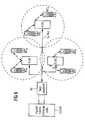
- FIG 2In the public small area - according to Figure 1 - may be operated according to FIG 2 as a cellular system to a private branch exchange PABX (P Rivat A utomatic B ranch E Xchange) a plurality of such telephone systems cordless, said PABX more base stations A-BS, B Controls BS, C-BS and possibly supports a handover from one base station to another.
- FIGURE 1also shows six mobile parts MT a ... MT f which are assigned to the three base stations A-BS, B-BS, C-BS.
- a cellular cordless telephone systemhas been created, in which the telecommunication connection is usually routed via the base station A-BS, B-BS, C-BS to which the handset MT a ... MT f maintains the best radio contact .
- FIGURE 3shows on the basis of the publication "Telecommunications Electronics 42 (1992) Jan./Feb., No. 1, Berlin, DE; U. Pilger: "Structure of the DECT standard", pages 23 to 29 in connection with ETS 300 175-1 ... 9, October 1992 " the TDMA structure of the STS DECT system.
- the DECT systemis a hybrid system with regard to multiple access methods, in accordance with the FDMA principle on ten frequencies in the frequency band between 1.88 and 1.90 GHz radio messages after the TDMA principle according to FIG 3 in a predetermined time Sequence from the base station BS to the handset MT and from the handset MT are sent to the base station BS (duplex operation) can.
- the time sequenceis a multi-time frame MZR determines that occurs every 160 ms and the 16th Has time frame ZR, each with a duration of 10 ms.
- time frame ZRare based on base station BS and handset MT separately transmit information that one in DECT standard defined C, M, N, P, Q channel concern. Become in a time frame ZR information for several of these Transmit channels, so the transmission takes place after a Priority list with M> C> N and P> N.
- Each of the 16 Time frame ZR of the multi-time frame MZRis in turn subdivided in 24 time slots ZS, each with a duration of 417 ⁇ s, of which 12 time slots ZS (time slots 0 ...
- time slots ZStime slots 12 ... 23
- mobile unit MT ⁇ base station BSare determined.
- time slots ZSaccording to the DECT standard information with a bit length of Transfer 480 bits.
- 32 bitsare used as synchronization information in a SYNC field and 388 bits as Transfer useful information in a D field.
- the remaining 60 Bitsare used as additional information in a Z field and as Transfer protection information in a "Guard-Time" field.
- the 388 bits of the D field transmitted as useful informationare subdivided into a 64-bit A field 320 bit long B field and a 4 bit long "X-CRC" word.
- the 64 bit long A fieldconsists of an 8 bit long data header (Header), a 40 bit data record with data for the C, Q, M, N, P channels and a 16 bit long "A-CRC" word together.
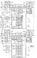
- FIGURE 4shows, starting from the publication Siemens Components 31 (1993), No. 6, pages 215 to 218; S. Althammer, D. Brückmann: "Highly optimized ICs for DECT cordless phones" the basic circuit structure of the base station BS and the handset MT.
- the base station BS and the mobile part MTthen have a radio part FKT with an antenna ANT assigned for transmitting and receiving radio signals, a signal processing device SVE and a central control ZST, which are connected to one another in the manner shown.
- the known devicessuch as transmitter SE, EM receiver and synthesizer SYN and a Feld Starmeß worn RSSI (R adio S ignal S trength ndicator I) being contained in substantially connected in a known manner.
- a coding / decoding device CODECis included in the signal processing device SVE.
- the central control ZSThas a microprocessor ⁇ P for the base station BS as well as for the mobile part MT with an according to the OSI / ISO layer model (cf. (1) : Struktursability - Irish Mathematics Jg. 48, 2/1995, pages 102 to 11 ; (2) : ETSI publication ETS 300175-1 ...
- the signal control part SSTis in the base station BS and T ime S witch C ontroller TSC and in the handset MT as B urst M ode C ontroller BMC formed.
- the main difference between the two signal control parts TSC, BMCis that the base station-specific signal control part TSC takes on additional switching functions (switch functions) compared to the mobile part-specific signal control part BMC.
- the signal control parts TSC, BMCeach contain a counting device ZE with a bit, time slot and time frame counter.
- FIGURE 4The circuit structure described in FIGURE 4 is used in the Base station BS and the handset MT according to their function in the DECT system according to FIGURE 2 by additional functional units added.
- the base station BSis via the signal processing device SVE and the telecommunications connection unit TAE or the private branch exchange with the telecommunications network TKN connected.
- the base station BScan have one Have user interface (dashed lines in FIGURE 4 Functional units) which e.g. from one as a keyboard trained input device EE, one as a display trained display device AE, one as a handset Speech / hearing device designed with MIF microphone and HK hearing capsule SHE and a TRK ringer.
- the mobile part MThas the option at the base station BS Possible user interface with the associated user interface belonging to the controls described above.
- the PABXlike the base station BS in the private sector with the wireline public telephone network PSTN (P ublic S witched T elephone N etwork) connected.
- PSTNpublic telephone network
- EP-0466736 B1is a cordless telephone system with a Private branch exchange known for building a cellular cordless telecommunications system performance features of the private branch exchange.
- a resulting increase in the interferencecan be with TDMA transmission method on which the DECT cordless telephone system is based be met.
- the TDMA procedureis just a time slot for the actual transmission second hand; the remaining eleven time slots can be used for measurements be used.
- Thisallows an alternative frequency / time slot pair be determined on which the connection can be switched.
- the DECT standardsees this in accordance with the communication technology Electronics 42 (Jan./Feb. 1992), No. 1, Berlin; U. Pilger: "Structure of the DECT standard”; Page 28, point 3.2.6 provides that the handset independently in the event of deterioration the transmission quality of the existing telecommunication connection due to the transmission quality Indicating indicators (e.g. signal field strength, CRC values etc.) parallel to the existing connection a second telecommunication connection builds up.
- Indicating indicatorse.g. signal field strength, CRC values etc.
- EP-0 529 359 A2is a private branch exchange with an integrated Handset known, with which can be operated via base stations, cordless devices can be controlled.
- the Private branch exchangehas freely configurable interface modules for this on.
- a central control unitis used for control for all switching and feature control tasks and a subordinate control unit for connection establishment / termination control the cordless end devices.
- the control units and the interface modulesare connected to each other via a BUS system.
- the object underlying the inventionis a to build cellular cordless telecommunications system that the realization of a variety of features, e.g. B. Synchronization, roaming, handover, internal connections, holding, Consultation, handover etc. of the cellular cordless telecommunication system without an additional wire connection between the cordless base stations of the cellular cordless telecommunication system enables.
- B. Synchronization, roaming, handover, internal connections, holding, Consultation, handover etc.of the cellular cordless telecommunication system without an additional wire connection between the cordless base stations of the cellular cordless telecommunication system enables.
- a first embodiment for realizing the "Handover" and other features, such as roamimg, hold, Questions, etc.,is based on FIGURE 1 using the FIGURES 5 and 6 explained.
- FIGURES 5 and 6The use of digital cordless devices in the form of a simple multi-cell solution can be as shown in FIGURES 5 and 6 are made.
- FIGURE 6illustrates the connection of cordless base stations via a network termination NT (N etwork T ermination) to a digital local exchange DOVST.
- NTNetwork etwork T ermination
- each S 0 busUp to eight cordless base stations can be connected to each S 0 bus, which are distributed as cheaply as possible within the radio range to be covered, taking into account the range of the S 0 bus (approx. 150 m).
- a mobile terminal(cordless subscriber) can be within of the network covered by radio cells move freely and both establish connections and receive calls.
- the handsetprovides the connection to the strongest base station who then takes over the conversation exclusively. With a going The cheapest base station is called automatically selected the handset and established the connection via this.
- a manual handover between two radio cells during a callis possible according to the principle of the Umsteckens on the bus by the feature TP (T erminal P ortability).
- the handsetdetermines that the range has been exceeded, the subscriber receives a warning signal that prompts him to take action. It sends a signal to the current base station, which in turn sends a request for the feature TP to the exchange (digital local exchange DOVST) or the Hicom private branch exchange PABX.
- the handsetthen sends a signal to the bass station with the best reception, which then takes over the call.
- the connectionis transferred to the new base station without triggering the B channel.
- the radio connectionmay be interrupted briefly during this process. To minimize the interruption time, the base stations should be operated synchronized. In the overlap area of several radio cells, constant switching is prevented by a sufficiently large hysteresis.
- An inquiry from an active callcan be made by initiating the Euro ISDN feature CH ( C all H old) and then dialing the desired number ("external" or "internal”).
- the CH featurecauses the current call to be put on hold, which can be coming or going.
- the B channel used up to nowis released for other actions of the initiating subscriber (accepting pending calls, establishing a further connection), which also enables a query or brokering.
- a handover before or after reporting a third terminalis through the Euro-ISDN feature ECT (E xplicit C all T ransfer) specified, but a launch date of this feature is not yet determined at the time. However, the preparation or implementation of this feature makes sense for future use.
- ECTE xplicit C all T ransfer
- a first exemplary embodiment for establishing the synchronization of the base stations on the S 0 bus and a second exemplary embodiment for realizing the "handover" of the cordless telephones on the S 0 busare explained with reference to FIGS. 7 and 8 in conjunction with FIGS. 2 to 6.
- a small multi-cell DECT cordless telecommunication systemis described, the base stations of which are connected by an ISDN S 0 bus as in the first exemplary embodiment.
- the systemoffers an increased range without additional cabling and can forward external calls almost without interruption if the user changes between the radio cells (base stations).
- the area of overlap of the radio fields of the base stationsneed not include the base stations themselves.
- the number of handsets in the entire telecommunications systemis increased. No further connection of calls within the radio cell of a base station (internal connection) is provided.
- the synchronicity of the base stations A-BS, B-BS, C-BSenables the mobile part MT c to select the base station A-BS, B-BS, C-BS that is most favorable in terms of radio technology for a connection, while the existing connection continues is held and without additional hardware is required in the MT c handset.
- a connection changecan be prepared in the background and carried out in a very short time. In a fully asynchronous system, the mobile part MT c would have to search almost all time slots (one time slot after the other) of the base stations A-BS, B-BS, C-BS arranged in the system after a connection loss.
- the base stations A-BS, B-BS, C-BShave the same reference clock available.
- This clockis jittery (max. ⁇ 7% of a bit period of 5.2 ⁇ s), but the long-term stability corresponds to that of the network node (max. ⁇ 10 -7 if the subscriber exchange is idle; min. ⁇ 10 -11 if the Subscriber exchange is synchronized by the reference clock).
- the frame clock of the DECT system (slave)is adapted to the ISDN clock (master) using a stuff bit method.
- a 10 ms frameis extended or shortened by half a bit period (1/2 x 868 ns).
- the DECT frames of the base stations A-BS, B-BS, C-BS on the S 0 busare now frequency-synchronized, but their phase position is indefinite and can differ from one another by a maximum of 5 ms (see FIGURE 7). To compensate for this 5 ms using stuffing bits, approx. 115 s would be required. After dismantling ISDN layer 1, the oscillators of the base stations A-BS, B-BS, C-BS drift away from each other. If one assumes that additional measures (e.g.
- DTCXOdigital temperature-compensated oscillator
- phase synchronism between the DECT base stations A-BS, B-BS, C-BS involved in the overall systemcan only be reached with the help of the S 0 bus in a sufficiently short time, and cannot be maintained for a significant time after the connection has been triggered can.
- the synchronism of the DECT framescan be dispensed with if the mobile part MT c completes its 10 ms time slot according to the dummy bearer provided by the DECT standard of another base station - in the present case the base station A-BS - searches. As can be seen from FIGURE 7, all other time slots apart from one time slot can be recorded. The concealment of a time slot by one's own base station - in this case the base station B-BS - does not matter if the base stations A-BS, B-BS, C-BS involved in the overall system determine the timing of the dummy bearer from a statistical point of view to change.
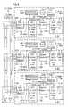
- the base stations A-BS, B-BS, C-BSeach have the circuit structure shown in principle in FIG. 8.
- the circuit structureessentially consists of the following modules or function blocks, a radio-technical function block consisting of a DECT radio section and DECT signal processing section FFB, a speech module SB, an ASIC module for data coupling into the B channel DEB, an ISDN layer 1 Module ISB with a transmission stage SES and a reception stage EMS as well as an additional receiver ZEM, which are connected in series in the order given between the antenna and the S 0 bus and which are controlled by a microprocessor MIP. Analogous to the microprocessor ⁇ P according to FIG. 4, the microprocessor MIP again contains a program module PGM with the implementation of the ISO / OSI layer model.
- the transmitting station A-BS, B-BS, C-BSreplaces the last bit (LSB) of a PCM octet with its signaling data for data transmission according to the "bit-stealing method" mentioned above.
- the other base stations A-BS, B-BS, C-BS involved in the overall systemreceive this information via the additional receiver ZEM (FIGURE 8), which is connected in parallel to its own S 0 transmission stage SES, without the specification of the ISDN layer -2 of the S 0 bus is violated (FIGURE 8).
- This methodoffers synchronous simplex data transmission with a maximum of 8000 baud, which is bought by a deterioration in the signal-to-noise ratio (theoretically by 6 dB) in the B-channel.
- the disturbances of the call connectionare kept within limits if, on the one hand, the data clock rate on e.g. B. 2000 baud is reduced, so only the last bit (LSB) of every fourth octet is used.
- a data packet with a length of 64 bytes (8 byte start flag, 52 byte data, 2 byte fuse, 2 byte stop flag)can be transmitted at 2000 baud in 256 ms. This short transmission time only slightly deteriorates the subjective transmission quality in the B channel.
- the base station B-BSnow uses a B-channel signaling to share the call data [TEI, RFPI ( R adio F ixed P art I dentity), IPUI ( I nternational P ortable U ser I dentity), B-Kanal etc.] other base stations A-BS, C-BS with.
- TEITerm Evolution
- RFPIR adio F ixed P art I dentity
- IPUII nternational P ortable U ser I dentity
- the mobile unit MT csearches in the background for dummy bearers from the other base stations A-BS, C-BS involved in the system. If the connection to the base station B-BS breaks or one of the other base stations A-BS, C-BS offers better radio field connections, the mobile part MT c "logs in" at this base station A-BS, C-BS. On the basis of the previously transmitted data, this base station A-BS, C-BS can re-assign its B channel to this mobile part MT c and switch it through virtually without delay. The base station B-BS blocks B-channel access after the loss of the mobile part MT c .
- the trigger commandis transmitted from the mobile part MT c to the base station A-BS, C-BS, which in turn transmits it to the base station B-BS via B-channel data.
- the base station B-BSthen triggers the connection via the D channel. This can be read by the base station A-BS, C-BS on the basis of the known TE number of the base station B-BS by evaluating the "release" of the exchange as a command.
- the operatorestablishes the call connection using the D-channel procedure with the base station B-BS. This can be done from the base station A-BS, C-BS based on the known TE number of the base station B-BS can be read by the "Release" of the Mediation is considered a command.
- the base station B-BSdoes not get any within a waiting period Message from one of the other base stations A-BS, C-BS via the B-channel signaling and clears the connection.
- the ISDN Layer 2must be able to process three different TE numbers in the direction of reception.
- the mobile part MT cmust be able to search for further base stations in the connection state.
- the analog part of the additional receiver ZEMcan be realized by a differential amplifier and a comparator. The rest of the signal processing is done digitally. Since critical tasks such as the regeneration of the S 0 clock continue to be derived from the ISDN layer 1 module ISB, which has an adaptive reception stage, this simple receiver should also have a range over the S 0 bus from 150 to 200 m depending on the cable type.
- the main part of the implementationis carried out by the system software, so that the system can be manufactured inexpensively.
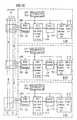
- FIGURE 9A second exemplary embodiment for establishing the synchronization of the base stations on the S 0 bus is explained with reference to FIGURE 9 in conjunction with FIGURES 2 to 6.
- the timing of the DECT system according to FIGURE 1 with the base stations A-BS, B-BS, C-BSis structured by the 10ms time frame ZR according to FIGURE 4 and by the 160ms multi-time frame MZR.
- an existing RF connection from a base station - for example the base station B-BS -be transferred to one of the other base stations A-BS, C-BS, because e.g. B. the mobile part MT c leaves the radio area of the base station B-BS, it is necessary that the base stations A-BS, B-BS, C-BS synchronize their clocks (frames) with each other.
- the base stations A-BS, B-BS, C-BSare connected by a common ISDN S 0 bus, that the synchronization of the base stations A-BS, B-BS, C-BS via the S 0 bus takes place and that the base stations A-BS, B-BS, C-BS based on FIG. 4 each have the circuit structure shown in principle in FIG. 9.
- the circuit structureessentially consists of the following modules or function blocks, a radio-technical function block consisting of a DECT radio section and DECT signal processing section FFB, a speech module SB, an ASIC module for data coupling into the B channel DEB, an ISDN layer 1 -Bod ISB with a transmission stage SES and a reception stage EMS, which are connected in series in the order specified between the antenna and the S 0 bus and which are controlled by a microprocessor MIP.
- the microprocessor MIPagain contains a program module PGM with the implementation of the ISO / OSI layer model.
- a synchronization signature generator SSGSYNC signature generator
- a memory module RAMare provided, which are connected in series in the order mentioned between the ISDN layer 1 module ISB and the microprocessor MIP.
- the base stations A-BS, B-BSobserved, C-BS the D-channel [in receiving direction ,, network termination NT (N etwork T ermination) ⁇ TE (T erminal e ndpoint) "].
- NTNetwork etwork T ermination
- TET erminal e ndpoint
- synchronization signatureCRC word + counter value
- the synchronization signaturesare continuously generated and stored in the ring memory RAM, which is a list (Signature table) of the signatures e.g. the last 5 seconds represents.
- This listis in all base stations A-BS, B-BS, C-BS is created almost synchronously, since the ISDN layer 1 in all base stations A-BS, B-BS, C -BS (terminal equipment TE) is started up at the same time (ISDN regulation).
- the base stations A-BS, B-BS, C-BSTo synchronize the base stations A-BS, B-BS, C-BS the last synchronization signature through the B channel or as packet data in the D channel to the base station A-BS, B-BS, C-BS transmitted with synchronization request.
- the base station A-BS, B-BS, C-BS with synchronization requestuses the 16 bit long CRC word to get the corresponding counter value in their list to find. From the difference between your own meter and the transmitted value results in the correction value for the DECT frame.
- a third exemplary embodiment for realizing the "handover" of the cordless telephones on the S 0 bus and a third exemplary embodiment for establishing the synchronization of the base stations on the S 0 busare explained with reference to FIGURES 10 to 15.
- a methodis described below by means of which the radio frame synchronization of base stations is possible which, for example, is locally connected to the S 0 bus of an ISDN base connection.
- the basic functions of the S 0 buscontain a function which fulfills the aspect a) and which is assumed here that, in principle, it should also meet the specific requirements of the synchronization problem dealt with here with regard to the time window.
- the S 0 buscontains an echo function as the basis for coordinating the access of connected stations to the D channel.
- the network termination NTrepresents the transition between 4-wire operation on the S 0 bus and 2-wire operation on the connection line to the telecommunications network and sends each of a device on the D-channel (base station) received bit back to the devices (base stations) as a so-called E bit in the E channel.
- the delay in the signal path between the transmission of a bit in the D channel and its reception as an echo in the E channel of the S 0 buscorresponds to the time of 2 bits (approx. 10 ⁇ s). This delay can also be compensated for in the application at hand [see points a) and b)].
- the e-channeldoes not have the disadvantage i). Under certain circumstances the disadvantage b) occur with the E channel if the E bit in similar form would be used for other purposes.
- the D channelAs for sending the synchronization message from the base station A-BS (MASTER station) the D channel is used must the synchronization signal also the basic conventions for the Meet Layer 2 message frames.
- FIGURE 13in connection with the publication: news electronics, Berlin; "Interfaces of Telecommunications" Part 4; 41 (1991), No. 6, pages 220 to 222 and 42 (1992), No. 1, pages 19 and 20], which is essentially characterized by a yet to be fixed SAPI-octet (S ervice A ccess P oint I dentifier).
- the SAPI codemust be from the responsible international standardization institutions ETSI and ITU (formerly CCITT) the value range reserved today.
- an application-specific SAPI valuecould be defined become. But it could also be such a value for local Applications, e.g. how to define the present. in the latter case can discriminate against other applications made according to known methods within the data field become.
- the layer 2 conventionallows a data field of max. 260 Octets.
- the synchronization signalcan therefore be a period of time up to approx. 130 ms, i.e. cover many radio frames.
- the receiving-side evaluation of the transmitted data backup informationdoes not appear to be necessary in the E-channel, since the S 0 bus itself is to be regarded as sufficiently reliable and there are no procedural measures other than "reading in” by the MASTER station and its reaction.
Landscapes
- Engineering & Computer Science (AREA)
- Computer Networks & Wireless Communication (AREA)
- Signal Processing (AREA)
- Mobile Radio Communication Systems (AREA)
Abstract
Description
Translated fromGermanDie Erfindung bezieht sich auf ein zellulares Schnurlos-Telekommunikationssystemgemäß dem Oberbegriff der Patentansprüche1 bis 3.The invention relates to a cellular cordless telecommunication systemaccording to the preamble of the
Das gegenwärtig leistungsfähigste Schnurlos-Telekommunikationssystembasiert auf dem DECT-Standard (DigitalEnhanced(früher:European)CordlessTelecommunications; vgl.(1):Nachrichtentechnik Elektronik 42 (Jan./Feb. 1992), No.1, Berlin;U. Pilger: "Struktur des DECT-Standards"; Seiten 23 bis29in Verbindung mit der ETSI-Publikation ETS 300175-1...9,Oktober 1992;(2): Siemens Components 31 (1993), No. 6; S.Althammer und D. Brückmann: "Hochoptimierte IC's für DECT-Schnurlostelefone",Seiten 215 bis 218;(3): telcom report 16(1993), No. 1, J.H. Koch: "Digitaler Komfort für schnurloseTelekommunikation - DECT-Standard eröffnet neue Nutzungssgebiete",Seiten 26 und 27), das Funknachrichten u. a. nach demTDMA-Verfahren (TimeDivisionMultipleAccess) überträgt.The currently most powerful cordless telecommunications system is based on the DECT standard (D igitalE nhanced (formerly:E uropean)C ordlessT elecommunications; cf.(1) : Kommunikationstechnik Electronics 42 (Jan./Feb. 1992), No.1, Berlin; U. Pilger: "Structure of the DECT standard"; pages 23 to 29in connection with the ETSI publication ETS 300175-1 ... October 9, 1992;(2) : Siemens Components 31 (1993), No. 6; S. Althammer and D. Brückmann: "Highly optimized IC's for DECT cordless phones", pages 215 to 218;(3) : telcom report 16 (1993), No. 1, JH Koch: "Digital convenience for cordless telecommunications - DECT -Standard opens up new areas of use ", pages 26 and 27), which transmits radio messages using the TDMA method (T imeD ivisionM ultipleA ccess).
Die vorliegende Erfindung ist jedoch nicht auf das TDMA-Übertragungsverfahrenbeschränkt. So erstreckt sich die Erfindungauch auf solche Systeme, die in der Druckschrift TIB-RO9067(5)-P.Bauer-Trocheris: "UMTS-Integrator für die mobileKommunikation - ein Ausblick auf die Mobilfunklandschaft nachdem Jahr 2000", Bericht über die Tagung "Europäischer Mobilfunk,5. Jahrestreffen der deutschen und europäischen Mobilfunkbranche,FIBA Kongresse, München 24. bis 26. Feb. 1993"aufgeführt sind.However, the present invention is not based on the TDMA transmission methodlimited. So the invention extendsalso on systems described in the document TIB-RO9067 (5) -P.Bauer-Trocheris: "UMTS integrator for the mobileCommunication - an outlook on the cellular landscapethe year 2000 ", report on the conference" European mobile communications,5th annual meeting of the German and European mobile communications industry,FIBA Congresses, Munich February 24th to 26th, 1993 "are listed.
Das DECT-spezifische Schnurlos-Telefonsystem ist ein digitalesSystem, das gemäß Figur 1 (vgl. tec 2/93 - Das technischeMagazin von Ascom "Wege zur universellen mobilen Telekommunikation",Seiten 35 bis 42) im privaten Bereich (z. B. Haus,Wohnung, Garten etc.) im öffentlichen Kleinbereich (z. B. Firmen, Bürohäuser etc.) und als Telepoint-Anwendung eingesetztwerden kann.The DECT-specific cordless telephone system is a digital oneSystem that according to Figure 1 (cf.
Das Schnurlos-Telefonsystem besteht in seiner Grundstrukturaus einer Basisstation BS (FP=FixedPart mit FT=FixedTermination)und einem mit der Basisstation BS telekommunikationsfähigenMobilteil MT (PP=PortablePart mit PT=PortableTermination). Diese Grundstruktur kann gemäß dem DECT-Standardderart erweitert werden, daß bis zu zwölf solcherMobilteile MT einer einzigen Basisstation BS zugeordnet werden.In its basic structure, the cordless telephone system consists of a base station BS (FP =F ixedP art with FT =F ixedT ermination) and a mobile part MT (PP =P ortableP art with PT =P ortableT ermination) that is telecommunications-capable with the base station BS ). This basic structure can be expanded in accordance with the DECT standard in such a way that up to twelve such mobile parts MT are assigned to a single base station BS.
FIGUR 2 zeigt ein solches Schnurlos-Telefonsystem STS, beidem an einer DECT-Basisstation BS über eine für den Frequenzbereichzwischen 1,88 und 1,90 GHz ausgelegte DECT-Luftschnittstellemaximal 12 Verbindungen nach demTDMA/FDMA/TDD-Verfahren (TimeDivisionMultipleAccess/FrequencyDivisionMultipleAccess/TimeDivisionDuplex)parallel zu DECT-Mobilteilen MT1...MT12 aufgebaut werden. DieZahl 12 ergibt sich aus einer Anzahl "k" von für den Duplex-betriebeines DECT-Systems zur Verfügung stehenden Zeitschlitzenbzw. Telekommunikationskanälen (k = 12). Die Verbindungenkönnen dabei intern und/oder extern sein. Bei einerinternen Verbindung können zwei an der Basisstation BS registrierteMobilteile, z. B. das Mobilteil MT2 und das MobilteilMT3, miteinander kommunizieren. Für den Aufbau einer externenVerbindung ist die Basisstation BS mit einem TelekommunikationsnetzTKN, z.B. in leitungsgebundener Form über eineTelekommunikationsanschlußeinheit TAE bzw. eine NebenstellenanlageNStA mit einem leitungsgebundenen Telekommunikationsnetzoder gemäß der WO 95/05040 in drahtloser Form als Repeaterstationmit einem übergeordneten Telekommunikationsnetz,verbunden. Bei der externen Verbindung kann man mit einemMobilteil, z. B. mit dem Mobilteil MT1, über die BasisstationBS, die Telekommunikationsanschlußeinheit TAE bzw.Nebenstellenanlage NStA mit einem Teilnehmer in dem TelekommunikationsnetzTKN kommunizieren. Besitzt die Basisstation BS - wie im Fall des Gigaset 951 (Siemens Schnurlostelefon,vgl. telcom Report 16, (1993) Heft 1, Seiten 26 und 27 - nureinen Anschluß zu der Telekommunikationsanschlußeinheit TAEbzw. der Nebenstellenanlage NStA, so kann nur eine externeVerbindung aufgebaut werden. Hat die Basisstation BS - wie imFall des Gigaset 952 (Siemens Schnurlostelefon; vgl. telcomReport 16, (1993), Heft 1, Seiten 26 und 27) - zwei Anschlüssezu dem Telekommunikationsnetz TKN, so ist zusätzlich zuder externen Verbindung mit dem Mobilteil MT1 eine weitereexterne Verbindung von einem an die Basisstation BS angeschlossenenleitungsgebundenen Telekommunikationsendgerät TKEmöglich. Dabei ist es prinzipiell auch vorstellbar, daß einzweites Mobilteil, z. B. das Mobilteil MT12, anstelle des TelekommunikationsendgerätesTKE den zweiten Anschluß für eineexterne Verbindung nutzt. Während die Mobilteile MT1...MT12mit einer Batterie oder einem Akkumulator betrieben werden,ist die als schnurlose Klein-Vermittlungsanlage ausgebildeteBasisstation BS über ein Netzanschlußgerät NAG an ein SpannungsnetzSPN angeschlossen.FIGURE 2 shows such a cordless telephone system STS, in which a DECT base station BS uses a DECT air interface designed for the frequency range between 1.88 and 1.90 GHz and a maximum of 12 connections according to the TDMA / FDMA / TDD method (T. imeD ivisionM ultipleA ccess /F requencyD ivisionM ultipleA ccess /T imeD ivisionD uplex) can be set up parallel to DECT handsets MT1 ... MT12. The
Das Schnurlos-Telefonsystem nach FIGUR 2 wird vorzugsweise indem privaten Bereich gemäß FIGUR 1 eingesetzt.The cordless telephone system of FIGURE 2 is preferably inthe private area shown in FIGURE 1.
Im öffentlichen Kleinbereich - gemäß FIGUR 1 - können mehreresolcher Schnurlos-Telefonsysteme nach FIGUR 2 als ein zellularesSystem an einer Nebenstellenanlage PABX (PrivatAutomaticBranchEXchange) betrieben werden, wobei die NebenstellenanlagePABX mehrere Basisstationen A-BS, B-BS, C-BS steuertund gegebenenfalls ein Handover von einer Basisstation zueiner anderen unterstützt. In FIGUR 1 sind weiterhin sechsMobilteile MTa...MTf dargestellt, die den drei BasisstationenA-BS, B-BS, C-BS zugeordnet sind. Auf diese Weise ist einzellulares Schnurlos-Telefonsystem entstanden, bei der dieTelekommunikationsverbindung in der Regel über diejenige BasisstationA-BS, B-BS, C-BS geführt wird, zu dem das MobilteilMTa...MTf den besten Funkkontakt unterhält.In the public small area - according to Figure 1 - may be operated according to FIG 2 as a cellular system to a private branch exchange PABX(P RivatA utomaticB ranchE Xchange) a plurality of such telephone systems cordless, said PABX more base stations A-BS, B Controls BS, C-BS and possibly supports a handover from one base station to another. FIGURE 1 also shows six mobile parts MTa ... MTf which are assigned to the three base stations A-BS, B-BS, C-BS. In this way, a cellular cordless telephone system has been created, in which the telecommunication connection is usually routed via the base station A-BS, B-BS, C-BS to which the handset MTa ... MTf maintains the best radio contact .
FIGUR 3 zeigt in Anlehnung an die Druckschrift"Nachrichtentechnik Elektronik 42 (1992) Jan./Feb., Nr. 1,Berlin, DE; U. Pilger: "Struktur des DECT-Standards", Seiten23 bis 29 in Verbindung mit ETS 300 175-1...9, Oktober 1992"die TDMA-Struktur des DECT-Systems STS. Das DECT-System istein bezüglich der Vielfachzugriffsverfahren hybrides System,bei dem nach dem FDMA-Prinzip auf zehn Frequenzen im Frequenzbandzwischen 1,88 und 1,90 GHz Funknachrichten nach demTDMA-Prinzip gemäß FIGUR 3 in einer vorgegebenen zeitlichenAbfolge von der Basisstation BS zum Mobilteil MT und vom MobilteilMT zur Basisstation BS (Duplex-Betrieb) gesendet werdenkönnen. Die zeitliche Abfolge wird dabei von einem Multi-ZeitrahmenMZR bestimmt, der alle 160 ms auftritt und der 16Zeitrahmen ZR mit jeweils einer Zeitdauer von 10 ms aufweist.In diesen Zeitrahmen ZR werden nach Basisstation BS und MobilteilMT getrennt Informationen übertragen, die einen imDECT-Standard definierten C-,M-,N-,P-,Q-Kanal betreffen. Werdenin einem Zeitrahmen ZR Informationen für mehrere dieserKanäle übertragen, so erfolgt die Übertragung nach einerPrioritätenliste mit M > C > N und P > N. Jeder der 16Zeitrahmen ZR des Multi-Zeitrahmens MZR unterteilt sich wiederumin 24 Zeitschlitze ZS mit jeweils einer Zeitdauer von417 µs, von denen 12 Zeitschlitze ZS (Zeitschlitze 0 ... 11)für die Übertragungsrichtung "Basisstation BS → MobilteilMT" und weitere 12 Zeitschlitze ZS (Zeitschlitze 12 ... 23)für die Übertragungsrichtung ,,Mobilteil MT → BasisstationBS" bestimmt sind. In jedem dieser Zeitschlitze ZS werdennach dem DECT-Standard Informationen mit einer Bitlänge von480 Bit übertragen. Von diesen 480 Bit werden 32 Bit als Synchronisationsinformationin einem SYNC-Feld und 388 Bit alsNutzinformation in einem D-Feld übertragen. Die restlichen 60Bit werden als Zusatzinformationen in einem Z-Feld und alsSchutzinformationen in einem Feld "Guard-Time" übertragen.Die als Nutzinformationen übertragenen 388 Bit des D-Feldesunterteilen sich wiederum in ein 64 Bit langes A-Feld, ein320 Bit langes B-Feld und ein 4 Bit langes "X-CRC"-Wort. Das64 Bit lange A-Feld setzt sich aus einem 8 Bit langen Datenkopf (Header), einem 40 Bit langen Datensatz mit Daten fürdie C-,Q-,M-,N-,P-Kanäle und einem 16 Bit langen "A-CRC"-Wortzusammen.FIGURE 3 shows on the basis of the publication"Telecommunications Electronics 42 (1992) Jan./Feb., No. 1,Berlin, DE; U. Pilger: "Structure of the DECT standard", pages23 to 29 in connection with ETS 300 175-1 ... 9, October 1992 "the TDMA structure of the STS DECT system. The DECT system isa hybrid system with regard to multiple access methods,in accordance with the FDMA principle on ten frequencies in the frequency bandbetween 1.88 and 1.90 GHz radio messages after theTDMA principle according to FIG 3 in a predetermined timeSequence from the base station BS to the handset MT and from the handsetMT are sent to the base station BS (duplex operation)can. The time sequence is a multi-time frameMZR determines that occurs every 160 ms and the 16thHas time frame ZR, each with a duration of 10 ms.In this time frame ZR are based on base station BS and handsetMT separately transmit information that one inDECT standard defined C, M, N, P, Q channel concern. Becomein a time frame ZR information for several of theseTransmit channels, so the transmission takes place after aPriority list with M> C> N and P> N. Each of the 16Time frame ZR of the multi-time frame MZR is in turn subdividedin 24 time slots ZS, each with a duration of417 µs, of which 12 time slots ZS (
FIGUR 4 zeigt ausgehend von der Druckschrift Siemens Components31 (1993), Heft 6, Seiten 215 bis 218; S. Althammer, D.Brückmann: "Hochoptimierte IC's für DECT-Schnurlostelefone"den prinzipiellen Schaltungsaufbau der Basisstation BS unddes Mobilteils MT. Die Basisstation BS und das Mobilteil MTweisen danach ein Funkteil FKT mit einer zum Senden und Empfangenvon Funksignalen zugeordneten Antenne ANT, eine SignalverarbeitungseinrichtungSVE und eine Zentrale SteuerungZST auf, die in der dargestellten Weise miteinander verbundensind. In dem Funkteil FKT sind im wesentlichen die bekanntenEinrichtungen wie Sender SE, Empfänger EM und Synthesizer SYNsowie eine Feldstärkemeßeinrichtung RSSI (RadioSignalStrengthIndicator) enthalten, die in bekannter Weise miteinanderverbunden sind. In der SignalverarbeitungseinrichtungSVE ist u.a. eine Kodier-/Dekodiereinrichtung CODEC enthalten.Die Zentrale Steuerung ZST weist sowohl für die BasisstationBS als für das Mobilteil MT einen Mikroprozessor µPmit einem nach dem OSI/ISO-Schichtenmodell (vgl.(1): Unterrichtsblätter- Deutsche Telekom Jg. 48, 2/1995, Seiten 102bis 11;(2): ETSI-Publikation ETS 300175-1...9, Oktober 1992)aufgebauten Programmodul PGM, einen Signalsteuerungsteil SSTund einen Digitalen Signalprozessor DSP auf, die in der dargestelltenWeise miteinander verbunden sind. Von den imSchichtenmodell definierten Schichten sind nur die unmittelbarfür die Basisstation BS und das Mobilteil MT wesentlichenersten vier Schichten dargestellt. Das SignalsteuerungsteilSST ist in der Basisstation BS alsTimeSwitchController TSCund in dem Mobilteil MT alsBurstModeController BMC ausgebildet.Der wesentliche Unterschied zwischen den beiden SignalsteuerungsteilenTSC, BMC besteht darin, daß der basisstationsspezifischeSignalsteuerungsteil TSC gegenüber demmobilteilspezifischen Signalsteuerungsteil BMC zusätzlichVermittlungsfunktionen (Switch-Funktionen) übernimmt. Die Signalsteuerungsteile TSC, BMC enthalten jeweils eine ZähleinrichtungZE mit einem Bit-, Zeitschlitz- und Zeitrahmenzähler.FIGURE 4 shows, starting from the publication Siemens Components 31 (1993), No. 6, pages 215 to 218; S. Althammer, D. Brückmann: "Highly optimized ICs for DECT cordless phones" the basic circuit structure of the base station BS and the handset MT. The base station BS and the mobile part MT then have a radio part FKT with an antenna ANT assigned for transmitting and receiving radio signals, a signal processing device SVE and a central control ZST, which are connected to one another in the manner shown. In the radio part FKT the known devices such as transmitter SE, EM receiver and synthesizer SYN and a Feldstärkemeßeinrichtung RSSI(R adioS ignalS trength ndicatorI) being contained in substantially connected in a known manner. A coding / decoding device CODEC is included in the signal processing device SVE. The central control ZST has a microprocessor µP for the base station BS as well as for the mobile part MT with an according to the OSI / ISO layer model (cf.(1) : Unterrichtsblätter - Deutsche Telekom Jg. 48, 2/1995, pages 102 to 11 ;(2) : ETSI publication ETS 300175-1 ... 9, October 1992) built program module PGM, a signal control part SST and a digital signal processor DSP, which are interconnected in the manner shown. Of the layers defined in the layer model, only the first four layers that are essential for the base station BS and the mobile part MT are shown. The signal control part SST is in the base station BS andT imeS witchC ontroller TSC and in the handset MT asB urstM odeC ontroller BMC formed. The main difference between the two signal control parts TSC, BMC is that the base station-specific signal control part TSC takes on additional switching functions (switch functions) compared to the mobile part-specific signal control part BMC. The signal control parts TSC, BMC each contain a counting device ZE with a bit, time slot and time frame counter.
Die prinzipielle Funktionsweise der vorstehend aufgeführtenSchaltungseinheiten ist beispielsweise in der vorstehend zitiertenDruckschrift Siemens Components 31 (1993), Heft 6,Seiten 215 bis 218 beschrieben.The principle of operation of the aboveCircuit units is, for example, in that cited abovePublication Siemens Components 31 (1993), No. 6,Pages 215 to 218.
Der beschriebene Schaltungsaufbau nach FIGUR 4 wird bei derBasisstation BS und dem Mobilteil MT gemäß deren Funktion indem DECT-System nach FIGUR 2 durch zusätzliche Funktionseinheitenergänzt.The circuit structure described in FIGURE 4 is used in theBase station BS and the handset MT according to their function inthe DECT system according to FIGURE 2 by additional functional unitsadded.
Die Basisstation BS ist über die SignalverarbeitungseinrichtungSVE und der Telekommunikationsanschlußeinheit TAE bzw.der Nebenstellenanlage NStA mit dem TelekommunikationsnetzTKN verbunden. Als Option kann die Basisstation BS noch eineBedienoberfläche aufweisen (in FIGUR 4 gestrichelt eingezeichneteFunktionseinheiten), die z.B. aus einer als Tastaturausgebildeten Eingabeeinrichtung EE, einer als Displayausgebildeten Anzeigeeinrichtung AE, einer als Handapparatmit Mikrofon MIF und Hörkapsel HK ausgebildeten Sprech/HöreinrichtungSHE sowie einer Tonrufklingel TRK betsteht.The base station BS is via the signal processing deviceSVE and the telecommunications connection unit TAE orthe private branch exchange with the telecommunications networkTKN connected. As an option, the base station BS can have oneHave user interface (dashed lines in FIGURE 4Functional units) which e.g. from one as a keyboardtrained input device EE, one as a displaytrained display device AE, one as a handsetSpeech / hearing device designed with MIF microphone and HK hearing capsuleSHE and a TRK ringer.
Das Mobilteil MT weist die bei der Basisstation BS als Optionmögliche Bedienoberfläche mit den zu dieser Bedienoberflächegehörenden vorstehend beschriebenen Bedienelementen auf.The mobile part MT has the option at the base station BSPossible user interface with the associated user interfacebelonging to the controls described above.
Die Nebenstellenanlage PABX gemäß FIGUR 1 ist wie die BasisstationBS im privaten Bereich mit dem leitungsgebundenen öffentlichenTelefonnetz PSTN (PublicSwitchedTelephoneNetwork)verbunden. Auf diese Weise kann jedermann durch die Anschaffungeiner Schnurlos-Telekommunikationsanlage, bestehendaus der Nebenstellenanlage PABX und den an dieser angeschlossenenSchnurlos-Telefonen A-BS, B-BS, C-BS, MTa...MTf zu seinemeigenen Netzbetreiber werden.The PABX according to FIGURE 1, like the base station BS in the private sector with the wireline public telephone network PSTN(P ublicS witchedT elephoneN etwork) connected. In this way, anyone can become their own network operator by purchasing a cordless telecommunications system consisting of the PABX private branch exchange and the cordless telephones A-BS, B-BS, C-BS, MTa ... MTf connected to it .
Aus der EP-0466736 B1 ist ein Schnurlos-Telefonsystem mit einerNebenstellenanlage bekannt, bei dem für den Aufbau eineszellularen Schnurlos-Telekommunikationssystems Leistungsmerkmaleder Nebenstellenanlage ausgenutzt werden.From EP-0466736 B1 is a cordless telephone system with aPrivate branch exchange known for building acellular cordless telecommunications system performance featuresof the private branch exchange.
Um auf eine Netz-Koordination von Schnurlostelefonen nach Figur1 verzichten zu können, ist gemäß dem DECT-Standard dasDynamicChannelAllocation-Verfahren (DCA-Verfahren) vorgesehen.Wenn z. B. eine DECT-Verbindung aufgebaut wird, wirddiejenige Frequenz und dasjenige Zeitfenster mit der geringstenInterferenz gesucht. Die Höhe (Stärke) der Interferenzhängt vorrangig davon ab, ob
Eine sich hieraus ergebende Erhöhung der Interferenz kann mitdem DECT-Schnurlostelefonsystem zugrundegelegten TDMA-Übertragungsverfahrenbegegnet werden. Nach dem TDMA-Verfahrenwird lediglich ein Zeitschlitz für die eigentliche Übertragunggebraucht; die übrigen elf Zeitschlitze können für Messungenverwendet werden. Dadurch kann ein alternatives Frequenz/Zeitschlitzpaarermittelt werden, auf das die Verbindungumgeschaltet werden kann. Dies geschieht im Rahmeneiner adaptiven Kanalzuweisung gemäß dem DECT-Standard (vgl.Nachrichtentechnik Elektronik 42 (Jan./Feb. 1992), No. 1,Berlin; U. Pilger: "Struktur des DECT-Standards"; Seite 28,Punkt 3.2.6) durch ein "Connection-Handover" (Intra-CellHandover).A resulting increase in the interference can be withTDMA transmission method on which the DECT cordless telephone system is basedbe met. According to the TDMA procedureis just a time slot for the actual transmissionsecond hand; the remaining eleven time slots can be used for measurementsbe used. This allows an alternative frequency / time slot pairbe determined on which the connectioncan be switched. This happens in the framean adaptive channel assignment according to the DECT standard (cf.Telecommunications Electronics 42 (Jan./Feb. 1992), No. 1,Berlin; U. Pilger: "Structure of the DECT standard"; Page 28,Point 3.2.6) through a "connection handover" (intra-cellHandover).
Neben diesem "Intra-Cell Handover" ist noch das "Inter-CellHandover" bzw. das seamless Handover zu nennen, das ebenfallsim Rahmen der DECT-spezifischen adaptiven Kanalzuweisung möglichist.In addition to this "intra-cell handover" is the "inter-cellHandover "or to call the seamless handover, that toopossible as part of the DECT-specific adaptive channel assignmentis.
Um nun insbesondere das bei zellularen drahtlosen Telekommunikationssystemenregelmäßig auftretende "Inter-Cell Hand-over"-Problemin den Griff zu bekommen, muß das für solchezellularen Funk-Telekommunikationssysteme vorgesehene mobileFunkempfangsgerät (Mobilteil) zu jedem Zeitpunkt einer aktivenTelekommunikationsverbindung zu einem (quasi)stationärenFunksendegerät (Basisstation) in der Lage sein, bedingt durcheinen Zellenwechsel innerhalb des zellularen Funksystems dieBasisstation zu wechseln (Aufbau einer Telekommunikationsverbindungzu einer anderen Basisstation) und dabei die bereitsbestehende aktive Telekommunikationsverbindung unterbrechungsfrei(seamless) an die andere Basisstation weiterzureichen(seamless Handover).Especially now in the case of cellular wireless telecommunication systems"Inter-cell hand-over" problem that occurs regularlyTo get a grip on that must be for suchcellular mobile telecommunication systems provided mobileRadio receiving device (handset) at any time an activeTelecommunication connection to a (quasi) stationaryRadio transmitter (base station) to be able to due toa cell change within the cellular radio systemChange base station (establishing a telecommunications connectionto another base station) while doing soexisting active telecommunications connection without interruption(seamlessly) to the other base station(seamless handover).
Der DECT-Standard sieht hierfür gemäß der Druckschrift NachrichtentechnikElektronik 42 (Jan./Feb. 1992), No. 1, Berlin;U. Pilger: "Struktur des DECT-Standards"; Seite 28, Punkt3.2.6 vor, daß das Mobilteil selbständig bei einer Verschlechterungder Übertragungsqualität der bestehenden Telekommunikationsverbindungaufgrund von die Übertragungsqualitätangebenden Indikatoren (z. B. Signalfeldstärke, CRC-Werteetc.) parallel zu der bestehenden Verbindung eine zweite Telekommunikationsverbindungaufbaut. Bei dieser "Inter-CellHandover"-Prozedur wird die Tatsache, daß DECT-Mobilteile imRahmen der dynamischen, dezentralisierten Kanalzuweisung(DCA-Verfahren) ständig über den Status der in der momentanenUmgebung verfügbaren Kanäle informiert sind, derart ausgenutzt,daß die zweite Verbindung aufgrund des Eintrages ineine Kanalliste aufgebaut wird.The DECT standard sees this in accordance with the communication technologyElectronics 42 (Jan./Feb. 1992), No. 1, Berlin;U. Pilger: "Structure of the DECT standard"; Page 28, point3.2.6 provides that the handset independently in the event of deteriorationthe transmission quality of the existing telecommunication connectiondue to the transmission qualityIndicating indicators (e.g. signal field strength, CRC valuesetc.) parallel to the existing connection a second telecommunication connectionbuilds up. With this "Inter-CellHandover "procedure is the fact that DECT handsets in theFramework of dynamic, decentralized channel allocation(DCA procedure) constantly on the status of the currentChannels available to the environment are informed,that the second connection due to the entry ina channel list is built.
Ein unterbrechungsfreies Handover ist mit der vorstehendenProzedur nur dann möglich, wenn das Mobilteil sich in einemzellularen Funksystem mit synchronisierten Basisstationen befindet.In einem solchen synchronen zellularen Funksystemkann das Mobilteil dann zusätzlich zu der bereits bestehendenTelekommunikationsverbindung zu einer Basisstation (Ursprungs-Basisstation)mindestens eine weitere Verbindung zu einer anderen Basisstation in einer anderen Funkzelle aufbauen,ohne dabei die Synchronität zur Ursprungs-Basisstation zuverlieren. Ein solches synchrones zellulares Funksystem kannaber nur mit erheblichem Systemaufwand (Kabel- oder Funksynchronisation)realisiert werden.An uninterrupted handover is with the aboveProcedure only possible if the handset is in onecellular radio system located with synchronized base stations.In such a synchronous cellular radio systemthe handset can then be added to the existing oneTelecommunication connection to a base station (source base station)at least one more connection toset up another base station in another radio cell,without synchronizing with the original base stationto lose. Such a synchronous cellular radio system canbut only with considerable system effort (cable or radio synchronization)will be realized.
Aus der US-5,388,102 ist eine Anordnung zum Synchronisiereneiner Vielzahl von Basisstationen eines drahtlosen Telekommunikationssystemsbekannt, die über ISDN-Basisanschlüsse aneine Vermittlungseinrichtung angeschlossen sind. Im Hinblickauf die Handover-Problematik in drahtlosen Telekommunikationssystemenist es zweckmäßig, wenn die in dem Telekommunikationssystemangeordneten Basisstationen untereinander synchronisiertsind. Zur Synchronisierung der Basisstationenwird deshalb ein Synchronisationssignal (Synchronisiernachricht)von der Vermittlungseinrichtung an die einzelnenBasisstationen im Rahmen eines zwischen der Vermittlungseinrichtungund den Basisstationen ablaufenden Kommunikationsprotokollsübertragen. Für den in der bekannten Anordnungverwendeten ISDN-Basisanschluß als Übertragungsmedium zwischender Vermittlungseinrichtung und den Basisstationen wirdbeispielsweise das S- oder M-Bit der ISDN-Datenstruktur alsTräger des Synchronisationssignals benutzt.An arrangement for synchronization is known from US Pat. No. 5,388,102a multiplicity of base stations of a wireless telecommunication systemknown that over ISDN basic connectionsa switching device is connected. With regardon the handover problem in wireless telecommunication systemsit is useful if the in the telecommunications systemarranged base stations synchronized with each otherare. To synchronize the base stationsis therefore a synchronization signal (synchronization message)from the switching facility to the individualBase stations as part of a between the switching centerand the communication protocol running on the base stationstransfer. For the in the known arrangementused ISDN base connection as a transmission medium betweenthe switching center and the base stationsfor example, the S or M bit of the ISDN data structure asCarrier of the synchronization signal used.
Aus der EP-0 529 359 A2 ist eine Nebenstellenanlage mit integriertemMobilteil bekannt, mit der über Basisstationen bedienbare,schnurlose Endgeräte gesteuert werden können. DieNebenstellenanlage weist hierzu frei konfigurierbare Schnittstellenmoduleauf. Zur Steuerung ist eine Zentralsteuereinheitfür alle Vermittlungs- und Leistungsmerkmalsteuerungsaufgabenund eine untergeordnete Steuereinheit zur Verbindungsaufbau-/abbausteuerungder schnurlosen Endgeräte vorgesehen.Die Steuereinheiten und die Schnittstellenmodule sindüber ein BUS-System miteinander verbunden. Mit der bekanntenNebenstellenanlage ist es ferner möglich, daß jedes schnurloseEndgerät überall innerhalb der Funkreichweite der Basisstationenerreichbar ist und daß bei einem Funkbereichswechsel des schnurlosen Endgerätes von einer Basisstation zu eineranderen Basisstation die bestehende Verbindung, gesteuertdurch die untergeordnete Steuereinheit, weitergereicht werdenkann.EP-0 529 359 A2 is a private branch exchange with an integratedHandset known, with which can be operated via base stations,cordless devices can be controlled. ThePrivate branch exchange has freely configurable interface modules for thison. A central control unit is used for controlfor all switching and feature control tasksand a subordinate control unit for connection establishment / termination controlthe cordless end devices.The control units and the interface modules areconnected to each other via a BUS system. With the knownPrivate branch exchange it is also possible that each cordlessTerminal anywhere within the radio range of the base stationscan be reached and that when there is a change in radio rangeof the cordless terminal from one base station to oneother base station controls the existing connectionby the subordinate control unitcan.
Die der Erfindung zugrundeliegende Aufgabe besteht darin, einzellulares Schnurlos-Telekommunikationssystem aufzubauen, dasdie Realisierung einer Vielzahl von Leistungsmerkmalen, z. B.Synchronisierung, Roaming, Handover, Internverbindungen, Halten,Rückfrage, Übergabe etc., des zellularen Schnurlos-Telekommunikationssystemsohne eine zusätzliche Drahtverbindungzwischen den Schnurlos-Basisstationen des zellularen Schnurlos-Telekommunikationssystemsermöglicht.The object underlying the invention is ato build cellular cordless telecommunications system thatthe realization of a variety of features, e.g. B.Synchronization, roaming, handover, internal connections, holding,Consultation, handover etc. of the cellular cordless telecommunication systemwithout an additional wire connectionbetween the cordless base stations of the cellular cordless telecommunication systemenables.
Diese Aufgabe wird ausgehend von dem in dem Oberbegriff derPatentansprüche 1 bis 3 definierten zellularen Schnurlos-Telekommunikationssystemsdurch die kennzeichnenden Merkmale der Patentansprüche1 bis 3 gelöst.This task is based on that in the preamble of
Vorteilhafte Weiterbildungen der Erfindung sind in den Unteransprüchenangegeben.Advantageous developments of the invention are in the subclaimsspecified.
Ein erstes Ausführungsbeispiel zur Realisierung des"Handover" und weiterer Leistungsmerkmale, wie Roamimg, Halten,Rückfragen etc., wird ausgehend von FIGUR 1 anhand derFIGUREN 5 und 6 erläutert.A first embodiment for realizing the"Handover" and other features, such as roamimg, hold,Questions, etc., is based on FIGURE 1 using theFIGURES 5 and 6 explained.
Die Benutzung von digitalen Schnurlos-Endgeräten in Form einereinfachen Mehrzellenlösung kann gemäß der Darstellung inden FIGUREN 5 und 6 vorgenommen werden.The use of digital cordless devices in the form of asimple multi-cell solution can be as shown inFIGURES 5 and 6 are made.
FIGUR 5 zeigt den Anschluß der Schnurlos-Basisstationen über
FIGUR 6 zeigt den Anschluß der Schnurlos-Basisstationen übereinen Netzabschluß NT (NetworkTermination) an eine DigitaleOrtsvermittlungsstelle DOVST.FIGURE 6 illustrates the connection of cordless base stations via a network termination NT(N etworkT ermination) to a digital local exchange DOVST.
An jeden S0-Bus können bis zu acht Schnurlos-Basisstationenangeschlossen werden, die innerhalb des abzudeckenden Funkbereichsunter Berücksichtigung der Reichweite des S0-Bus (ca.150 m) zur Erreichung einer Flächendeckung möglichst günstigverteilt werden.Up to eight cordless base stations can be connected to each S0 bus, which are distributed as cheaply as possible within the radio range to be covered, taking into account the range of the S0 bus (approx. 150 m).
Im Euro-ISDN-Standard (vgl. Nachrichtentechnik Elektronik,Berlin, 44(1994) Heft 1, Seiten 16 bis 18) ist es allgemein -bei einem S0-Busanschluß über die MSN (MultipleSubscriberNumber) - möglich, den an einen S0-Bus angeschlossenen Endgerätenunterschiedliche Rufnummern zuzuteilen. Diese Rufnummernfür die einzelnen Geräte können sowohl komplett voneinanderverschieden sein als auch nur die n-letzten Stellen derRufnummer umfassen, wobei n ≥ 1 sein kann. Hierbei ist esmöglich, einem Endgerät auch mehrere Mehrfachnummern (MNS)zuzuteilen. Jede angeschlossene Basisstation kann über mehrerebzw. alle vorhandenen Mehrfachnummern (MNS) erreicht werden.An jeder Basisstation sind zudem alle EndgerätekennungenTEI (TerminalEndpointIdentifier) der Mobilteile durch einmaligeAnmeldung aller Mobilteile bekannt und den verschiedenenMehrfachnummern eindeutig zugeordnet.In the Euro-ISDN standard (cf. Nachrichtenentechnik Elektronik, Berlin, 44 (1994)
Zur Zeit ist die Anzahl der möglichen Mehrfachrufnummern beider DBP Telekom zunächst auf m = 10 (NDL m = 8) beschränkt.Beim Anschluß an der Hicom-Nebenstellenanlage (PABX) sind dieMobilteile über die Durchwahlnummer des S0-Bus und eine daranangehängte einstellige Pseudo-MSN erreichbar, wobei nur dieseletzte Ziffer an den Bus gegeben und dort ausgewertet wird.Dabei ist die "0" im allgemeinen für die Anwahl aller angeschlossenen Endgeräte reserviert und die Ziffern "1" bis "8"für die einzelnen Endgeräte. Bei Anlagenanschluß mit mehr alseinem S0-Bus wäre auch ein größerer Wert für m denkbar (z. B.2-stellig), da nur die Basisstationen die MSN auswerten. Indiesem Fall müßte sichergestellt sein, daß die Basisstationenauf die Gesamtzahl der vergebenen MSN`s einstellbar sind.At the moment the number of possible multiple phone numbers at DBP Telekom is initially limited to m = 10 (NDL m = 8). When connecting to the Hicom private branch exchange (PABX), the handsets can be reached via the extension number of the S0 bus and a single-digit pseudo-MSN attached to it, whereby only this last digit is sent to the bus and evaluated there. The "0" is generally reserved for the selection of all connected devices and the numbers "1" to "8" for the individual devices. If the system was connected to more than one S0 bus, a larger value for m would also be conceivable (e.g. 2 digits), since only the base stations evaluate the MSN. In this case it should be ensured that the base stations can be set to the total number of MSNs assigned.
Eine mobile Endstelle (Schnurlos-Teilnehmer) kann sich innerhalbdes durch Funkzellen abgedeckten Netzes frei bewegen undsowohl Verbindungen aufbauen als auch Rufe empfangen.A mobile terminal (cordless subscriber) can be withinof the network covered by radio cells move freely andboth establish connections and receive calls.
Bei einem kommenden Ruf werten alle Basisstationen die kommendeMSN aus und senden einen Ruf für das gewünschte Mobilteilmit der entsprechenden Endgerätekennung TEI. Das gerufeneMobilteil stellt die Verbindung zur stärksten Basisstationher, die dann das Gespräch exklusiv übernimmt. Bei einem gehendenRuf wird die günstigste Basisstation automatisch durchdas Mobilteil gewählt und über diese die Verbindung aufgebaut.With an incoming call, all base stations evaluate the coming oneMSN and send a call for the desired handsetwith the corresponding terminal device identifier TEI. The calledThe handset provides the connection to the strongest base stationwho then takes over the conversation exclusively. With a goingThe cheapest base station is called automaticallyselected the handset and established the connection via this.
Bei einem Anschluß hinter der Hicom-Nebenstellenanlage (PABX)mit mehr als einem S0-Bus erhalten bei einem ankommenden Ruffür ein Mobilteil ebenfalls alle Basisstationen Signalisierungen(Rufzuordnung durch die Hicom-Nebenstellenanlage) undrufen das gewünschte Mobilteil. Die erste Station, die dasMobilteil erreicht, erhält das Gespräch. Dadurch kann ein Mobilteilauch in den Funkbereichen unterschiedlicher S0-Busselokalisiert werden.If there is a connection behind the Hicom private branch exchange (PABX) with more than one S0 bus, when there is an incoming call for a handset, all base stations also receive signaling (call assignment by the Hicom private branch exchange) and call the desired handset. The first station that reaches the handset receives the call. This means that a handset can also be located in the radio areas of different S0 buses.
Ein manuelles Handover zwischen zwei Funkzellen während einesGesprächs (Intercell Handover) ist nach dem Prinzip des Umsteckensam Bus durch das Leistungsmerkmal TP (TerminalPortability)möglich. Bei Feststellen einer Reichweitenüberschreitung durch das Mobilteil erhält der Teilnehmer einWarnsignal, das ihn zu einer Aktion auffordert. Er sendet einSignal an die aktuelle Basisstation, die wiederum eine Anforderungfür das Merkmal TP an das Amt (Digitale OrtsvermittlungsstelleDOVST) bzw. die Hicom-Nebenstellenanlage PABXschickt. Das Mobilteil sendet anschließend ein Signal zu derempfangsmäßig besten Bassisstation, die dann das Gesprächübernimmt. Die Verbindung wird dabei ohne Auslösen des B-Kanalsan die neue Basisstation übergeben. Während diesesVorgangs kann es je nach Umschaltdauer der Basisstationen zueiner kurzen Unterbrechung der Funkverbindung kommen. Um dieUnterbrechungszeit zu minimieren, sollten die Basisstationensynchronisiert betrieben werden. Im Überlappungsbereich mehrererFunkzellen wird ein ständiges Umschalten durch eineausreichend große Hysterese unterbunden.A manual handover between two radio cells during a call (intercell handover) is possible according to the principle of the Umsteckens on the bus by the feature TP(T erminalP ortability). If the handset determines that the range has been exceeded, the subscriber receives a warning signal that prompts him to take action. It sends a signal to the current base station, which in turn sends a request for the feature TP to the exchange (digital local exchange DOVST) or the Hicom private branch exchange PABX. The handset then sends a signal to the bass station with the best reception, which then takes over the call. The connection is transferred to the new base station without triggering the B channel. Depending on the switching time of the base stations, the radio connection may be interrupted briefly during this process. To minimize the interruption time, the base stations should be operated synchronized. In the overlap area of several radio cells, constant switching is prevented by a sufficiently large hysteresis.
Aus Sicht des Amtes besteht kein Unterschied zwischen Extern-und Internverbindung. Internverbindungen zwischen unterschiedlichenBasisstationen an einem Bus sind daher nur alsExternverbindung über das Amt möglich. Internverbindungen innerhalbdes Funkbereichs einer Basisstation werden über dieserealisiert unabhängig vom Amt realisiert.From the Office's point of view, there is no difference between externaland internal connection. Internal connections between differentBase stations on a bus are therefore only asExternal connection possible via the office. Internal connections withinof the radio range of a base station are via thisrealized independently of the office.
Eine Rückfrage aus einem aktiven Gespräch heraus kann durchEinleiten des Euro-ISDN-Leistungsmerkmals CH (CallHold) undanschließender Wahl der gewünschten Nummer ("extern" oder"intern") erfolgen. Das Merkmal CH bewirkt ein Halten des aktuellenGesprächs, wobei dieses kommend oder gehend seinkann. Der bisher benutzte B-Kanal wird dabei für andere Aktionendes einleitenden Teilnehmers freigegeben (Annahme ankopfenderRufe, Herstellen einer weiteren Verbindung), wodurchauch eine Rückfrage oder Makeln möglich wird.An inquiry from an active call can be made by initiating the Euro ISDN feature CH (C allH old) and then dialing the desired number ("external" or "internal"). The CH feature causes the current call to be put on hold, which can be coming or going. The B channel used up to now is released for other actions of the initiating subscriber (accepting pending calls, establishing a further connection), which also enables a query or brokering.
Eine Übergabe vor bzw. nach Melden einer dritten Endstelleist durch das Euro-ISDN-Leistungsmerkmal ECT (ExplicitCallTransfer) spezifiziert, jedoch ist ein Einführungstermin diesesLeistungsmerkmals zur Zeit noch nicht festgelegt. DieVorbereitung bzw. Realisierung dieses Merkmals ist jedochsinnvoll für einen zukünftigen Einsatz.A handover before or after reporting a third terminal is through the Euro-ISDN feature ECT(E xplicitC allT ransfer) specified, but a launch date of this feature is not yet determined at the time. However, the preparation or implementation of this feature makes sense for future use.
Ein erstes Ausführungsbeispiel zur Herstellung der Synchronisationder Basisstationen am S0-Bus und ein zweites Ausführungsbeispielzur Realisierung des "Handover" der Schnurlostelefoneam S0-Bus werden anhand der FIGUREN 7 und 8 in Verbindungmit den FIGUREN 2 bis 6 erläutert.A first exemplary embodiment for establishing the synchronization of the base stations on the S0 bus and a second exemplary embodiment for realizing the "handover" of the cordless telephones on the S0 bus are explained with reference to FIGS. 7 and 8 in conjunction with FIGS. 2 to 6.
Es wird ein kleines mehrzelliges DECT-Schnurlostelekommunikationssystembeschrieben, dessen Basisstationen wie bei demersten Ausführungsbeispiel durch einen ISDN-S0-Bus verbundensind. Das System bietet dabei ohne zusätzliche Verkabelungeine Erhöhung der Reichweite und kann externe Gespräche nahezuunterbrechungsfrei weiterreichen, wenn der Benutzer zwischenden Funkzellen (Basisstationen) wechselt. Der Überlappungsbereichder Funkfelder der Basisstationen muß nichtdie Basisstationen selbst einschließen. Außerdem wird die Anzahlder Mobilteile in dem gesamten Telekommunikationssystemerhöht. Eine Weiterverbindung von Gesprächen innerhalb derFunkzelle einer Basisstation (Internverbindung) ist nichtvorgesehen.A small multi-cell DECT cordless telecommunication system is described, the base stations of which are connected by an ISDN S0 bus as in the first exemplary embodiment. The system offers an increased range without additional cabling and can forward external calls almost without interruption if the user changes between the radio cells (base stations). The area of overlap of the radio fields of the base stations need not include the base stations themselves. In addition, the number of handsets in the entire telecommunications system is increased. No further connection of calls within the radio cell of a base station (internal connection) is provided.
Durch die Synchronität der Basisstationen A-BS, B-BS, C-BSwird es dem Mobilteil MTc ermöglicht, die jeweils funktechnischgünstigste Basisstation A-BS, B-BS, C-BS für eine Verbindungauszuwählen, während die bestehende Verbindung weitergehalten wird und ohne daß im Mobilteil MTc ein zusätzlicherHardware-Aufwand erforderlich ist. Ein Verbindungswechselkann im Hintergrund vorbereitet und in sehr kurzer Zeitdurchgeführt werden. In einem voll asynchronen System würdedas Mobilteil MTc nach Verbindungsverlust fast alle Zeitschlitze(einen Zeitschlitz nach dem anderen) der in dem System angeordneten Basisstationen A-BS, B-BS, C-BS absuchenmüssen.The synchronicity of the base stations A-BS, B-BS, C-BS enables the mobile part MTc to select the base station A-BS, B-BS, C-BS that is most favorable in terms of radio technology for a connection, while the existing connection continues is held and without additional hardware is required in the MTc handset. A connection change can be prepared in the background and carried out in a very short time. In a fully asynchronous system, the mobile part MTc would have to search almost all time slots (one time slot after the other) of the base stations A-BS, B-BS, C-BS arranged in the system after a connection loss.
Nach Aufbau der ISDN-Schicht-1 des S0-Bus steht den BasisstationenA-BS, B-BS, C-BS der gleiche Referenztakt zur Verfügung.Dieser Takt ist zwar jitterbehaftet (max. ± 7 % einerBitperiode von 5,2 µs), aber die Langzeitstabilität entsprichtder des Netzknotens (max. ± 10-7, wenn die Teilnehmervermittlungsstellefrei läuft; min. ± 10-11, wenn dieTeilnehmervermittlungsstelle durch den Bezugstakt synchronisiertwird). Durch ein Stopfbitverfahren wird der Rahmentaktdes DECT-Systems (Slave) an den ISDN-Takt (Master) angepaßt.Ein 10 ms-Rahmen wird hierbei um eine halbe Bitperiode (1/2 x868 ns) verlängert oder verkürzt. Die DECT-Rahmen der BasisstationenA-BS, B-BS, C-BS am S0-Bus sind nun zwar frequenzsynchronisiert,aber ihre Phasenlage ist unbestimmt und kannum maximal 5 ms voneinander abweichen (vgl. FIGUR 7). Um diese5 ms durch Stopfbits auszugleichen, würden ca. 115 s benötigtwerden. Nach Abbau der ISDN-Schicht 1 driften die Oszillatorender Basisstationen A-BS, B-BS, C-BS voneinander weg.Geht man davon aus, daß durch zusätzliche Maßnahmen (z. B.durch einen digitalen temperaturkompensierten OszillatorDTCXO) die Stabilität um eine Größenordnung von den in derDECT-Spezifikation (Standard) geforderten 5 ppm auf 0,5 ppmverbessert wird, würden die DECT-Stationen A-BS, B-BS, C-BStrotzdem bereits nach 1,7 s asynchron werden. Dabei wird einVersatz von einem Bit als Asynchronität betrachtet.After the
Dies zeigt, daß eine Phasensynchronität zwischen den am Gesamtsystembeteiligten DECT-Basisstationen A-BS, B-BS, C-BSnur mit Hilfe des S0-Bus weder in hinreichend kurzer Zeit erreichbarist noch für eine nennenswerte Zeit nach der Verbindungsauslösungaufrechterhalten werden kann.This shows that phase synchronism between the DECT base stations A-BS, B-BS, C-BS involved in the overall system can only be reached with the help of the S0 bus in a sufficiently short time, and cannot be maintained for a significant time after the connection has been triggered can.
Bei bestehender Frequenzsynchronität der Basisstationen A-BS,B-BS, C-BS kann auf die Synchronität der DECT-Rahmen verzichtetwerden, wenn das Mobilteil MTc seinen vollen 10 ms-Zeitschlitz nach im DECT-Standard vorgesehenen Dummy-Bearereiner anderen Basisstation - im vorliegenden Fall der BasisstationA-BS - absucht. Wie aus der FIGUR 7 entnommen werdenkann, können bis auf einen Zeitschlitz alle anderen Zeitschlitzeerfaßt werden. Die Verdeckung eines Zeitschlitzesdurch die eigene Basisstation - im vorliegenden Fall die BasisstationB-BS - fällt dann nicht ins Gewicht, wenn die amGesamtsystem beteiligten Basisstationen A-BS, B-BS, C-BS dieZeitlage des Dummy-Bearer nach statistischen Gesichtspunktenändern.If the base stations A-BS, B-BS, C-BS have frequency synchronism, the synchronism of the DECT frames can be dispensed with if the mobile part MTc completes its 10 ms time slot according to the dummy bearer provided by the DECT standard of another base station - in the present case the base station A-BS - searches. As can be seen from FIGURE 7, all other time slots apart from one time slot can be recorded. The concealment of a time slot by one's own base station - in this case the base station B-BS - does not matter if the base stations A-BS, B-BS, C-BS involved in the overall system determine the timing of the dummy bearer from a statistical point of view to change.
Die Übertragung von Daten zwischen den DECT-Basisstationen A-BBS,B-BS, C-BS erfolgt über das letzte Bit (LSB =LastSignificantBit) eines aktiven B-Kanals nach der "Bit-Stealing-Methode".Die Basisstationen A-BS, B-BS, C-BS haben ausgehendvon FIGUR 4 jeweils den in FIGUR 8 prinzipiell dargestelltenSchaltungsaufbau. Der Schaltungsaufbau besteht dabei im wesentlichenaus folgenden Bausteinen bzw. Funktionsblöcken,einem funktechnischen Funktionsblock aus DECT-Funkteil undDECT-Signalverarbeitungsteil FFB, einem Sprachbaustein SB,einem als ASIC ausgebildeten Baustein zur Dateneinkopplung inden B-Kanal DEB, einem ISDN-Schicht-1-Baustein ISB mit einerSendestufe SES und einer Empfangsstufe EMS sowie einem ZusatzempfängerZEM, die in der angegebenen Reihenfolge zwischender Antenne und dem S0-Bus in Serie geschaltet sind unddie von einem Mikroprozessor MIP gesteuert werden. Der MikroprozessorMIP enthält analog zu dem Mikroprozessor µP nachFIGUR 4 wieder ein Programmodul PGM mit der Realisierung desISO/OSI-Schichtenmodells.The transfer of data between the DECT base stations A-BBS, BBS, C-BS takes place via the last bit (LSB =L astS ignificantB it) an active B-channel according to the "bit-stealing method". Starting from FIG. 4, the base stations A-BS, B-BS, C-BS each have the circuit structure shown in principle in FIG. 8. The circuit structure essentially consists of the following modules or function blocks, a radio-technical function block consisting of a DECT radio section and DECT signal processing section FFB, a speech module SB, an ASIC module for data coupling into the B channel DEB, an
Für die Datenübertragung nach der vorstehend erwähnten "Bit-Stealing-Methode"ersetzt die sendende Station A-BS, B-BS, C-BSdas letzte Bit (LSB) eines PCM-Oktetts durch ihre Signalisierungsdaten.Die anderen am Gesamtsystem beteiligten BasisstationenA-BS, B-BS, C-BS empfangen diese Information über den Zusatzempfänger ZEM (FIGUR 8), der zu ihrer eigenen S0-SendestufeSES parallel geschaltet wird, ohne daß die Spezifikationder ISDN-Schicht-2 des S0-Bus verletzt wird (FIGUR8). Diese Methode bietet eine synchrone Simplex-Datenübertragungmit maximal 8000 Baud, die durch eine Verschlechterungdes Störabstandes (theoretisch um 6 dB) im B-Kanalerkauft wird. Die Störungen der Gesprächsverbindungwerden in Grenzen gehalten, wenn zum einen die Datentaktrateauf z. B. 2000 Baud reduziert wird, also nur noch das letzteBit (LSB) jedes vierten Oktetts benutzt werden. Es wird einÜbertragungsverfahren ähnlich dem HDLC-Verfahren (HighDataLinkControl) verwendet. Ein Datenpaket von 64 Byte Länge (8Byte Startflag, 52 Byte Daten, 2 Byte Sicherung, 2 Byte Stopflag)kann bei 2000 Baud in 256 ms übertragen werden. Diesekurze Übertragungszeit verschlechtert die subjektive Übertragungsqualitätim B-Kanal nur unwesentlich.The transmitting station A-BS, B-BS, C-BS replaces the last bit (LSB) of a PCM octet with its signaling data for data transmission according to the "bit-stealing method" mentioned above. The other base stations A-BS, B-BS, C-BS involved in the overall system receive this information via the additional receiver ZEM (FIGURE 8), which is connected in parallel to its own S0 transmission stage SES, without the specification of the ISDN layer -2 of the S0 bus is violated (FIGURE 8). This method offers synchronous simplex data transmission with a maximum of 8000 baud, which is bought by a deterioration in the signal-to-noise ratio (theoretically by 6 dB) in the B-channel. The disturbances of the call connection are kept within limits if, on the one hand, the data clock rate on e.g. B. 2000 baud is reduced, so only the last bit (LSB) of every fourth octet is used. There is a transfer method similar to the HDLC-process(H ighD ataL ink ontrolC) was used. A data packet with a length of 64 bytes (8 byte start flag, 52 byte data, 2 byte fuse, 2 byte stop flag) can be transmitted at 2000 baud in 256 ms. This short transmission time only slightly deteriorates the subjective transmission quality in the B channel.
Das Mobilteil MTc hat sich bei der Basisstation B-BS"eingeloggt" und baut über den D-Kanal der Basisstation B-BSein Externgespräch mit einem B-Teilnehmer auf. Aus Sicht derVermittlungseinrichtung ist der B-Kanal, über den das Gesprächgeführt wird, einer bestimmten TE-Nummer (TEI =TerminalEndpointIdentifier) dieses S0-Bus zugeordnet. Diese Zuordnungkönnte nur durch Leistungsmerkmale der Vermittlung(Terminal Portability; vgl. erstes Ausführungsbeispiel) geändertwerden. Die Basisstation B-BS teilt nun über eine B-Kanal-Signalisierungdie Gesprächsdaten [TEI, RFPI (RadioFixedPartIdentity), IPUI (InternationalPortableUserIdentity),B-Kanal etc.] den anderen Basisstationen A-BS, C-BSmit.The mobile unit MTc has “logged in” at the base station B-BS and is setting up an external call with a B subscriber via the D channel of the base station B-BS. From the viewpoint of the switching device is the B-channel, the call is routed via the assigned0 bus a certain number TE (TEI =T erminalE ndpoint dentifierI) of this S. This assignment could only be changed by performance features of the exchange (terminal portability; cf. first exemplary embodiment). The base station B-BS now uses a B-channel signaling to share the call data [TEI, RFPI (R adioF ixedP artI dentity), IPUI (I nternationalP ortableU serI dentity), B-Kanal etc.] other base stations A-BS, C-BS with.
Während des Gespräches sucht das Mobilteil MTc im Hintergrundnach Dummy-Bearer der anderen am System beteiligten BasisstationenA-BS, C-BS. Reißt die Verbindung zur Basisstation B-BSab oder bietet eine der anderen Basisstationen A-BS, C-BSbessere Funkfeldverbindungen, so "loggt" sich das MobilteilMTc bei dieser Basisstation A-BS, C-BS ein. Anhand der vorherübermittelten Daten kann diese Basisstation A-BS, C-BS diesemMobilteil MTc ihren B-Kanal wiederzuordnen und quasi verzögerungslosdurchschalten. Die Basisstation B-BS sperrt nachVerlust des Mobilteils MTc den B-Kanalzugriff.During the call, the mobile unit MTc searches in the background for dummy bearers from the other base stations A-BS, C-BS involved in the system. If the connection to the base station B-BS breaks or one of the other base stations A-BS, C-BS offers better radio field connections, the mobile part MTc "logs in" at this base station A-BS, C-BS. On the basis of the previously transmitted data, this base station A-BS, C-BS can re-assign its B channel to this mobile part MTc and switch it through virtually without delay. The base station B-BS blocks B-channel access after the loss of the mobile part MTc .
Das Auslösekommando wird vom Mobilteil MTc zur BasisstationA-BS, C-BS übertragen, die es wiederum per B-Kanal-Daten zurBasisstation B-BS überträgt. Die Basisstation B-BS löst dannüber den D-Kanal die Verbindung aus. Dies kann von der BasisstationA-BS, C-BS anhand der bekannten TE-Nummer der BasisstationB-BS mitgelesen werden, indem das "Release" der Vermittlungals Kommando gewertet wird.The trigger command is transmitted from the mobile part MTc to the base station A-BS, C-BS, which in turn transmits it to the base station B-BS via B-channel data. The base station B-BS then triggers the connection via the D channel. This can be read by the base station A-BS, C-BS on the basis of the known TE number of the base station B-BS by evaluating the "release" of the exchange as a command.
Die Vermittlung baut per D-Kanal-Prozedur die Gesprächsverbindungmit der Basisstation B-BS ab. Dies kann von der BasisstationA-BS, C-BS anhand der bekannten TE-Nummer der BasisstationB-BS mitgelesen werden, indem das "Release" derVermittlung als Kommando gewertet wird.The operator establishes the call connection using the D-channel procedurewith the base station B-BS. This can be done from the base stationA-BS, C-BS based on the known TE number of the base stationB-BS can be read by the "Release" of theMediation is considered a command.
Die Basisstation B-BS bekommt innerhalb einer Karenzzeit keineMeldung von einer der anderen Basisstationen A-BS, C-BSüber die B-Kanal-Signalisierung und baut die Verbindung ab.The base station B-BS does not get any within a waiting periodMessage from one of the other base stations A-BS, C-BSvia the B-channel signaling and clears the connection.
Die ISDN-Schicht-2 muß in der Lage sein, drei verschiedeneTE-Nummern in Empfangsrichtung zu verarbeiten. Das MobilteilMTc muß im Verbindungszustand in der Lage sein, nach weiterenBasisstationen zu suchen. Der Analogteil des ZusatzempfängersZEM kann durch einen Differenzverstärker und einen Komparatorrealisiert werden. Die restliche Signalverarbeitung erfolgtdigital. Da kritische Aufgaben, wie das Regenerieren des S0-Taktesweiterhin von dem ISDN-Schicht-1-Baustein ISB abgeleitetwerden, der über eine adaptive Empfangsstufe verfügt,sollte auch mit diesem einfachen Empfänger eine Reichweiteüber den S0-Bus von 150 bis 200 m je nach Kabeltyp realisiertwerden können. Der Hauptteil der Realisierung wird durch dieSystemsoftware getragen, so daß das System kostengünstig hergestelltwerden kann.The
Beim Aufbau oder einer späteren Erweiterung des Gesamtsystemsmuß zwischen den Basisstationen und Mobilteilen ein Datenaustauschstattfinden (RFPI, IPUI, etc. gemäß DECT-Standard).Dieser Aufwand und die damit verbundenen Fehlermöglichkeitenkönnen verringert werden, wenn die Basisstationen des Systemsdiese Daten bei einer Änderung über die B-Kanal-Signalisierungden am S0-Bus angeschlossenen Basisstationen mitteilen.Diese Daten können dann von den Basisstationen in die Mobilteilekopiert werden. Zur Konfiguration des Gesamtsystems(genauer: Anmeldung anderer Basisstationen und Mobilteile)reicht es also aus, wenn von jeder Basisstation ein Externgesprächgeführt wird.When setting up or later expanding the overall system, data exchange must take place between the base stations and mobile units (RFPI, IPUI, etc. according to the DECT standard). This effort and the associated error possibilities can be reduced if the base stations of the system communicate this data to the base stations connected to the S0 bus in the event of a change via the B-channel signaling. This data can then be copied from the base stations to the handsets. To configure the entire system (more precisely: registering other base stations and handsets), it is therefore sufficient if an external call is made from each base station.
Ein zweites Ausführungsbeispiel zur Herstellung der Synchronisationder Basisstationen am S0-Bus wird anhand der FIGUR 9in Verbindung mit den FIGUREN 2 bis 6 erläutert.A second exemplary embodiment for establishing the synchronization of the base stations on the S0 bus is explained with reference to FIGURE 9 in conjunction with FIGURES 2 to 6.
Das Timing des DECT-Systems nach FIGUR 1 mit den BasissstationenA-BS, B-BS, C-BS wird durch den 10ms-Zeitrahmen ZRnach FIGUR 4 und durch den 160ms-Multi-Zeitrahmen MZR strukturiert.Soll eine bestehende HF-Verbindung von einer Basisstation- z.B. die Basisstation B-BS - auf eine der anderenBasisstationen A-BS, C-BS umgelegt werden, weil z. B. das MobilteilMTc den Funkbereich der Basisstation B-BS verläßt,ist es erforderlich, daß die Basisstationen A-BS, B-BS, C-BSihre Takte (Rahmen) miteinander synchronisieren.The timing of the DECT system according to FIGURE 1 with the base stations A-BS, B-BS, C-BS is structured by the 10ms time frame ZR according to FIGURE 4 and by the 160ms multi-time frame MZR. Should an existing RF connection from a base station - for example the base station B-BS - be transferred to one of the other base stations A-BS, C-BS, because e.g. B. the mobile part MTc leaves the radio area of the base station B-BS, it is necessary that the base stations A-BS, B-BS, C-BS synchronize their clocks (frames) with each other.
Durch diese Maßnahme ist es möglich, eine HF-Verbindung zwischenBasisstationen, die keine Funkverbindung miteinanderhaben, zu übergeben, ohne daß es für den Benutzer zu spürbarenStörungen kommt.This measure makes it possible to establish an HF connection betweenBase stations that have no radio connection with each otherhave to pass without being felt by the userInterference comes.
Im weiteren wird davon ausgegangen, daß die Basisstationen A-BS,B-BS, C-BS durch einen gemeinsamen ISDN- S0-Bus verbundensind, daß die Synchronisation der Basisstationen A-BS, B-BS,C-BS über den S0-Bus erfolgt und daß die Basisstationen A-BS,B-BS, C-BS ausgehend von FIGUR 4 jeweils den in FIGUR 9 prinzipielldargestellten Schaltungsaufbau haben.It is further assumed that the base stations A-BS, B-BS, C-BS are connected by a common ISDN S0 bus, that the synchronization of the base stations A-BS, B-BS, C-BS via the S0 bus takes place and that the base stations A-BS, B-BS, C-BS based on FIG. 4 each have the circuit structure shown in principle in FIG. 9.
Der Schaltungsaufbau besteht dabei im wesentlichen aus folgendenBausteinen bzw. Funktionsblöcken, einem funktechnischenFunktionsblock aus DECT-Funkteil und DECT-SignalverarbeitungsteilFFB, einem Sprachbaustein SB, einemals ASIC ausgebildeten Baustein zur Dateneinkopplung in denB-Kanal DEB, einem ISDN-Schicht-1-Baustein ISB mit einer SendestufeSES und einer Empfangsstufe EMS, die in der angegebenenReihenfolge zwischen der Antenne und dem S0-Bus in Seriegeschaltet sind und die von einem Mikroprozessor MIP gesteuertwerden. Der Mikroprozessor MIP enthält analog zu dem MikroprozessorµP nach FIGUR 4 wieder ein Programmodul PGM mitder Realisierung des ISO/OSI-Schichtenmodells. Darüber hinaussind noch ein Synchronisationssignatur-Generator SSG (SYNC-Signatur-Generator)und ein Speicherbaustein RAM vorgesehen,die in der genannten Reihenfolge zwischen dem ISDN-Schicht-1-Baustein ISB und dem Mikroprozessor MIP in Serie geschaltetsind.The circuit structure essentially consists of the following modules or function blocks, a radio-technical function block consisting of a DECT radio section and DECT signal processing section FFB, a speech module SB, an ASIC module for data coupling into the B channel DEB, an ISDN layer 1 -Bod ISB with a transmission stage SES and a reception stage EMS, which are connected in series in the order specified between the antenna and the S0 bus and which are controlled by a microprocessor MIP. Analogous to the microprocessor µP according to FIG. 4, the microprocessor MIP again contains a program module PGM with the implementation of the ISO / OSI layer model. In addition, a synchronization signature generator SSG (SYNC signature generator) and a memory module RAM are provided, which are connected in series in the order mentioned between the
Bisher wurde die Synchronisation - wie bereits eingangs erwähnt- über eine separate Verkabelung zwischen den Basisstationenerreicht.So far, the synchronization - as already mentioned at the beginning- via separate cabling between the base stationsreached.
Nach Aufbau der ISDN-Schicht-1 im ISDN-Schicht-1-Baustein ISBbeobachten die Basisstationen A-BS, B-BS, C-BS den D-Kanal inEmpfangsrichtung [Richtung ,,Netzabschluß NT (NetworkTermination)→ Endeinrichtung TE (TerminalEndpoint)"]. Nachdem einStart-Flag (Oktett 01111110) erkannt wurde, wird aus den nunfolgenden 32 Bits (oder mehr), ohne weitere Diskriminierung,ein 16 Bit langes CRC-Wort gebildet (CycleRedundancyCheck).After construction of the
Weiterhin wird bei Beginn eines DECT-Multi-Zeitrrahmens MZRein Zähler gestartet, der nach Bildung des CRC-Wortes angehaltenund dessen Zählerwert ausgelesen wird.Furthermore, at the beginning of a DECT multi-time frame MZRstarted a counter that stopped after the formation of the CRC wordand its counter value is read out.
Auf diese Weise wid eine Synchronisationssignatur (Synchronisationssignatur= CRC-Wort + Zählerwert) generiert, die dasDECT-Timing mit dem S0-Bus-Timing verknüpft.In this way, a synchronization signature (synchronization signature = CRC word + counter value) is generated, which links the DECT timing with the S0 bus timing.
Die Synchronisationssignaturen werden fortlaufend erzeugt undin dem Ringspeicher RAM abgelegt, der eine Liste(Signaturtabelle) der Signaturen z.B. der letzten 5 Sekundendarstellt. Diese Liste wird in allen Basisstationen A-BS, B-BS,C-BS quasi synchron erstellt, da die ISDN-Schicht-1 inallen Basisstationen A-BS, B-BS, C -BS (Endeinrichtungen TE)gleichzeitig hochgefahren wird (ISDN-Vorschrift).The synchronization signatures are continuously generated andstored in the ring memory RAM, which is a list(Signature table) of the signatures e.g. the last 5 secondsrepresents. This list is in all base stations A-BS, B-BS,C-BS is created almost synchronously, since the
Zur Synchronisation der Basisstationen A-BS, B-BS, C-BS wirddie letzte Synchronisationssignatur durch den B-Kanal oderals Paketdaten im D-Kanal zur Basisstation A-BS, B-BS, C-BSmit Synchronisationswunsch übertragen. Die Basisstation A-BS,B-BS, C-BS mit Synchronisationswunsch benutzt das 16 Bit langeCRC-Wort, um in ihrer Liste den entsprechenden Zählerwert zu finden. Aus der Differenz zwischen eigenem Zähler und demübermittelten Wert ergibt sich der Korrekturwert für denDECT-Rahmen.To synchronize the base stations A-BS, B-BS, C-BSthe last synchronization signature through the B channel oras packet data in the D channel to the base station A-BS, B-BS, C-BStransmitted with synchronization request. The base station A-BS,B-BS, C-BS with synchronization request uses the 16 bit longCRC word to get the corresponding counter value in their listto find. From the difference between your own meter and thetransmitted value results in the correction value for theDECT frame.
Ein drittes Ausführungsbeispiel zur Realisierung des"Handover" der Schnurlostelefone am S0-Bus und ein drittesAusführungsbeispiel zur Herstellung der Synchronisation derBasisstationen am S0-Bus werden anhand der FIGUREN 10 bis 15erläutert.A third exemplary embodiment for realizing the "handover" of the cordless telephones on the S0 bus and a third exemplary embodiment for establishing the synchronization of the base stations on the S0 bus are explained with reference to FIGURES 10 to 15.
- Allgemeine ProblemstellungFolgende Konfiguration mit dem Telekommunikationsnetz wirdbehandelt:
- Die Basisstationen A-BS, B-BS, C-BS zwischen denen dasHandover stattfinden kann, sind an denselben S0-Bus einesBasisanschlusses des ISDN (IntegratedServicesDigitalNetwork; vgl. Druckschrift "Nachrichtentechnik Elektronik,Berlin 45,Teil: 1 bis 10,T1: (1991) Heft 3, Seiten99 bis 102;T2: (1991) Heft 4, Seiten 138 bis 143;T3:(1991) Heft 5, Seiten 179 bis 182 und Heft 6, Seiten 219bis 220;T4: (1991) Heft 6, Seiten 220 bis 222 und (1992)Heft 1, Seiten 19 bis 20;T5: (1992) Heft 2, Seiten 59bis 62 und (1992) Heft 3, Seiten 99 bis 102;T6: (1992)Heft 4, Seiten 150 bis 153;T7: (1992) Heft 6, Seiten 238bis 241;T8: (1993) Heft 1, Seiten 29 bis 33;T9: (1993)Heft 2, Seiten 95 bis 97 und (1993) Heft 3, Seiten 129bis 135;T10: (1993) Heft 4, Seiten 187 bis190;")angeschlossen (FIGUREN 5 und 6).
- An der Schnittstelle zum S0-Bus werden nur solche Grundfunktionenvorausgesetzt, die derzeit an der Schnittstelleund im Telekommunikationsnetz verfügbar sind. Die Basisstationen A-BS, B-BS, C-BS haben ausgehend vonFIGUR 4 jeweils den in FIGUR 10 prinzipiell dargestelltenSchaltungsaufbau. Der Schaltungsaufbau besteht dabeiim wesentlichen aus folgenden Bausteinen bzw. Funktionsblöcken,einem funktechnischen Funktionsblock aus DECT-Funkteilund DECT-Signalverarbeitungsteil FFB, einemSprachbaustein SB, einem als ASIC ausgebildeten Bausteinzur Dateneinkopplung in den B-Kanal DEB sowie einemISDN-Schicht-1-Baustein ISB mit einer Sendestufe SES undeiner Empfangsstufe EMS, die in der angegebenen Reihenfolgezwischen der Antenne und dem S0-Bus in Serie geschaltetsind und die von einem Mikroprozessor MIP gesteuertwerden. Der Mikroprozessor MIP enthält analog zudem Mikroprozessor µP nach FIGUR 4 wieder ein ProgrammodulPGM mit der Realisierung des ISO/OSI-Schichtenmodells.
- Die Anschaltung der Basisstationen A-BS, B-BS, C-BS anden S0-Bus kann gemäß der FIGUREN 11 und 12 auf unterschiedlicheWeise, insbesondere auf der Basis unterschiedlicherArchitekturmodelle erfolgen. Für FIGUR 12gilt dabei beispielsweise:
- 1 ○ Schnittstellenanpassung zur Aufbereitung von E-Bits derart,daß Verwendung durch Standard HDLC-Empfänger (HighDataLinkControl) möglich [vgl. FIGUR 13 in Verbindungmit der Druckschrift: Nachrichtentechnik Elektronik,Berlin; "Schnittstellen der Telekommunkation" Teil 4;41(1991),Heft 6, Seiten 220 bis 222 und 42(1992), Heft1, Seiten 19 und 20].
- 2 ○ HDLC-Hardwarefunktion: Empfangsseitig mit Schnittstelleüber Mikroprozessor-Bus zum Software-Teil im Mikroprozessor.
- 3 ○ Hardware-Ausweitung zur Rahmensynchronisierung mit definiertenEchtzeitverhalten. Dabei ist es auch möglich,direkt auf das E-Bit aufzusetzen. Es werden alle Funktionenohne Unterstützung des Mikrocontrollers abgewikkelt.Wesentliche Basisfunktionen von HDLC sind:
- HDLC-Rahmensynchronisierung
- Ausblendung der Einfügungsbits
- CRC-Behandlung
- Auswertung SAPI/TEI [vgl. FIGUR 13 in Verbindung mitder Druckschrift: Nachrichtentechnik Elektronik, Berlin;"Schnittstellen der Telekommunkation" Teil 4;41(1991),Heft 6, Seiten 220 bis 222 und 42(1992), Heft1, Seiten 19 und 20].
- ggf. Auswertung des Info-Feldes [vgl. FIGUR 13 in Verbindungmit der Druckschrift: Nachrichtentechnik Elektronik,Berlin; "Schnittstellen der Telekommunkation"Teil 4; 41(1991),Heft 6, Seiten 220 bis 222 und42(1992), Heft 1, Seiten 19 und 20].
- 4 ○ Schicht-1-Funktionen
Hier ist die Erzeugung eines zusätzlichen Signales Tvorstellbar, mit dem die Schicht 1-Funktion meldet, daßein zu sendender D-Kanal-Frame den Zugriff zum S0-Buserhalten hat und gesendet wird. Dabei wird die Erkennungund Prüfung der eigenen gesendeten Information beim Mithörenim E-Kanal. Diese Funktion könnte aber auch direktauf dem E-Bit selbst aufbauen und in 1) und/oder 3) implementiertwerden.
- The base stations A-BS, B-BS, C-BS can between which held the handover,0 bus are in the same S a base terminal of the ISDN(IntegratedServicesDigital Network;. Cf. publication "Nachrichtentechnik Elektronik, Berlin 45 ,P art: 1 to 10,T 1: (1991)
Heft 3, pages 99 to 102;T 2: (1991)Heft 4, pages 138 to 143;T 3: (1991)Heft 5, pp 179-182 andBook 6, pages 219 to 220;T 4: (1991)Book 6, pages 220 to 222 and (1992)Book 1, pages 19 to 20;T 5: (1992)Book 2, pages 59 to 62 and (1992)Book 3, pages 99 to 102;T 6: (1992)Book 4, pages 150 to 153;T 7: (1992)Book 6, pages 238 to 241;T 8: (1993)Book 1, pages 29 to 33;T 9: (1993)issue 2, pages 95 to 97 and (1993)issue 3, pages 129 to 135;T 10: (1993)issue 4, pages 187 to 190; ") connected (FIGURES 5 and 6). - Only basic functions that are currently available at the interface and in the telecommunications network are required at the interface to the S0 bus. Starting from FIG. 4, the base stations A-BS, B-BS, C-BS each have the circuit structure shown in principle in FIG. 10. The circuit structure essentially consists of the following modules or function blocks, a radio-technical function block consisting of a DECT radio section and DECT signal processing section FFB, a speech module SB, an ASIC module for data coupling into the B channel DEB and an ISDN layer 1 -Bod ISB with a transmission stage SES and a reception stage EMS, which are connected in series in the order specified between the antenna and the S0 bus and which are controlled by a microprocessor MIP. Analogous to the microprocessor µP according to FIG. 4, the microprocessor MIP again contains a program module PGM with the implementation of the ISO / OSI layer model.
- The base stations A-BS, B-BS, C-BS can be connected to the S0 bus in accordance with FIGURES 11 and 12 in different ways, in particular on the basis of different architecture models. For FIGURE 12 the following applies, for example:
- 1 ○ interface adaptation for the preparation of E-bits such that use by standard HDLC-receiver(H ighD ataLC ontrol ink) is possible [cp. FIGURE 13 in connection with the publication: news electronics, Berlin; "Interfaces of Telecommunications"
Part 4; 41 (1991),volume 6, pages 220 to 222 and 42 (1992),volume 1, pages 19 and 20]. - 2 ○ HDLC hardware function: Receiving side with interface via microprocessor bus to the software part in the microprocessor.
- 3 ○ Hardware expansion for frame synchronization with defined real-time behavior. It is also possible to use the E-Bit directly. All functions are handled without the support of the microcontroller. The essential basic functions of HDLC are:
- HDLC frame synchronization
- Hiding the insertion bits
- CRC treatment
- SAPI / TEI evaluation [cf. FIGURE 13 in connection with the publication: news electronics, Berlin; "Interfaces of Telecommunications"
Part 4; 41 (1991),volume 6, pages 220 to 222 and 42 (1992),volume 1, pages 19 and 20]. - If necessary, evaluation of the info field [cf. FIGURE 13 in connection with the publication: news electronics, Berlin; "Interfaces of Telecommunications"
Part 4; 41 (1991),volume 6, pages 220 to 222 and 42 (1992),volume 1, pages 19 and 20].
- 4 ○
Layer 1 functions
Here, the generation of an additional signal T is conceivable, with which thelayer 1 function reports that a D-channel frame to be transmitted has received access to the S0 bus and is being transmitted. The detection and checking of your own transmitted information when listening in the E-channel. This function could also be built directly on the E-Bit itself and implemented in 1) and / or 3).
Bei der betrachteten Konfiguration wird davon ausgegangen,daß die DECT-Struktur einschließlich der Handover-Funktionerhalten bleibt.The configuration under consideration assumesthat the DECT structure including the handover functionpreserved.
Die Handover-Funktion ist Bestandteil der Mobilitätsfunktionenin der drahtlosen Telekommunikation. Als "Handover" wirdhier folgende Funktion betrachtet:
Daraus ergibt sich für die Basisstationen B-BS, A- BS am S0-Busfolgendes:
- Lösungsprinzipien
- Lokale QuerkommunikationZur Verwendung vorgeschlagen wird gemäß FIGUR 14 ein Informationskanalbestehend aus dem D-Kanal (Sende- und Empfangsrichtung)und dem E-Kanal (Echo-D-Kanal) [vgl. II.Verfahrenzur Rahmensynchronisierung der Luftschnittstelle" von DECT-Basisstationenüber den S0
-Bus der ISDN-Netzschnittstelle ].Dabei wird zusätzlich die dort erwähnte erweiterte Nutzbarkeitzugrundegelegt. Der E-Kanal ist ein Kanal, auf dem diein dem Netzabschluß NT durch eine Echofunktion veränderte D-Kanalinformationübertragen wird.- Jede Basisstation A-BS, B-BS erhält neben einer SendeeinrichtungSED und einer Empfangseinrichtung EED für den D-Kanalauch am E-Kanal eine Empfangseinrichtung EEE, dieidentische Grundfunktionen wie die am D-Kanal hat, alsoden üblichen Format-Konventionen der HDLC-Protokolle genügt.
FIGUR 14 zeigt ein Prinzipschaltbild dieser Konfiguration. - Format, Adressen
- Basis für die Querkommunikation ist das Format "UnumberedInformation Frame" (UI-Rahmen) nach den Konventionen desD-Kanal-Schicht-2-Protokolls (LAP-D) [vgl.
FIGUR 13 inVerbindung mit der Druckschrift: Nachrichtentechnik Elektronik,Berlin; "Schnittstellen der Telekommunkation"Teil 4; 41(1991),Heft 6, Seiten 220 bis 222 und 42(1992),Heft 1, Seiten 19 und 20]. - SAPI (ServiceAccessPointIdentifier)
- Bei Standardisierungsgremien (z.B. ITU, ETSI) aus dem reserviertenBereich in Standards zu definieren (muß mitTelekommunikationsnetz kompatibel sein).
- TEI (TerminalEndpointIdentifier) : Wert: 127 dec
- Weitere anwendungsspezifische Adressen: Im Datenfeld desUI-Rahmen. Dieser kann damit im Grundsatz physikalisch an alle Basisstationen A-BS, B-BS, C-BS gesendet werden(broadcasting). Selektivität kann soweit erforderlichnach anwendungsspezifischen Gesichtspunkten gestaltetwerden.
- Basis für die Querkommunikation ist das Format "UnumberedInformation Frame" (UI-Rahmen) nach den Konventionen desD-Kanal-Schicht-2-Protokolls (LAP-D) [vgl.
- Fehlersicherung, Behebung
Redundanz und Fehlererkennung entsprechen der LAP-D-Konvention.Darauf aufbauend wird für die Fehlerbehebungnachstehend skizziertes Verfahren vorgeschlagen. UnterBerücksichtigung des lokalen Charakters des Übertragungswegesim S0-Bus wird dabei folgendes angenommen:- Das Faktum "Frame richtig/falsch empfangen" wird von allenBasisstationen A-BS, B-BS, C-BS gleichsinning erkannt.Daraus folgt, daß auch die jeweils im D-Kanal sendendeBasisstation A-BS, B-BS, C-BS selbst im E-Kanal das Faktum"richtig/falsch" erkennen kann. Gegebenenfalls kannsie eine Wiederholung der Übertragung anstoßen, ohne daßexplizite Quittierung durch die empfangenden Baisstationennötig ist. Zur Identifizierung solcher lokal gesendetenUI-Rahmen sind die Basisstationen A-BS, B-BS deshalbim sendeseitigen D-Kanal mit einer Teileinrichtung ausgerüstet,die definitiv erkennt, wenn ein solcher UI-Rahmenden Zugriff zum D-Kanal erhalten hat und übertragen wird.Damit kann ein solcher Rahmen unter Echtzeitbedingungenaus der Folge aller im D-Kanal gesendeten Rahmen selektivherausgefiltert und analysiert werden.Die zeitliche Zuordnung Senden/Empfangen wird durch dengegebenen festen Bitversatz in der Echofunktion "D-Kanal→ E-Kanal" ermöglicht.
- Sonstige Funktionen
Die Empfänger am E-Kanal können auch zusätzlich mit einerTeileinrichtung versehen werden, die eine Echtzeitanalysedes Rahmeninhaltes während des Einlaufes des Bitstromeserlaubt. Wurde ein Rahmen fehlerfrei empfangen, liegendamit unmittelbar nach Rahmenende Schaltkriterien fürkürzest mögliche Reaktionen vor. Zur Reaktionszeitverkürzungbei längeren Rahmen kann auch eine abschnittweise Zwischensicherung bei der sendenden Basisstation und denempfangenden Basisstationen vorgesehen werden.
- Jede Basisstation A-BS, B-BS erhält neben einer SendeeinrichtungSED und einer Empfangseinrichtung EED für den D-Kanalauch am E-Kanal eine Empfangseinrichtung EEE, dieidentische Grundfunktionen wie die am D-Kanal hat, alsoden üblichen Format-Konventionen der HDLC-Protokolle genügt.
- Verfahren zur Übergabe/Übernahme der VerbindungAufbauend auf dielokale Querkommunikation enthält das Verfahrenweiterhin folgende Prozedurschritte:
- a)
- Nach Erkennung einer Handover-Anforderung des bestimmtenMobilteils MTc (identifiziert durch seine Kennung) sendetdie Basisstation A-BS ein Telegramm mit folgendem Inhalt:
- Absender: Adresse A-BS
- Empfänger: Alle Basisstationen
- Kommando: Handover-Anforderung
- MTc -Identität: Es wird davon ausgegangen, daß das MobilteilMTc nur eine Verbindung hat. Andernfalls müssen dieVerbindungen zusätzlich identifiziert werden.
- Die Basisstation B-BS (steuert die Verbindung mit dem MobilteilMTc) erkennt die Identität des Mobilteils MTc.
- Nach Erkennung einer Handover-Anforderung des bestimmtenMobilteils MTc (identifiziert durch seine Kennung) sendetdie Basisstation A-BS ein Telegramm mit folgendem Inhalt:
- b) Die Basisstation B-BS übergibt dann in einem selektivenTelegramm an die Basisstation A-BS alle aktuellen relevantenParameter wie:
- ISDN-Schicht 2: TEI, Laufnummernvariable, Prozeßzustand
- ISDN-Schicht 3: B-Kanal, Callreferenz, Rufzustand
- DECT-Schicht 3: Transaktion-Identifizierung, Rufzustand.
- c)
- Die Basisstation A-BS installiert nach Empfang entsprechendsynchrone interne Steuerungsprozesse und startetdie Analyse von Protokollaktivitäten am D-Kanal und ander DECT-Schnittstelle. Die Basisstation A-BS bleibt aberzunächst weiter passiv.
- Die Basisstation A-BS bestätigt den Verfahrensschritt c)mit einem selektiven Bestätigungstelegramm an die BasissstationB-BS.
- d) Fallverzweigung:
- d1) Hat die Basisstation B-BS zwischenzeitlich keine dieseverbindung betreffende Protokollaktivität des Telekommunikationsnetzes empfangen oder des Mobilteils MTc erkannt,wird die Übergabe der Initiative zur Weiterführungder Verbindung in einem selektiven Telegramm an die BasisstationA-BS bestätigt.
- d2)
- Wird zwischenzeitlich aufgrund von TEI-Managementaktioneneine Erneuerung des TEI für die ISDN-Schicht-2 Verbindungund deren Wiederaufbau erforderlich, führt die BasisstationB-BS diese Aktion durch und storniert und aktualisiertdie entsprechenen Parameter bei der Basisstation A-BSnach Verfahrensschritt b).
- Fortsetzung: Schritte c), dl) usw.
- d3) Wird zwischenzeitlich eine andere Schicht-2 Informationdiese Verbindung betreffend im D-Kanal empfangen (auchbereits von der Basisstation A-BS erkennbar), reagiertdie Basisstation B-BS mit dem verfahrensschritt d1). DieBbasisstation A-BS führt die Prozedur dann fort.Anmerkung: Es wird davon ausgegangen, daß die Übergabe"Basisstation B-BS → Basisstation A-BS" normalerweiseinnerhalb der gegebenen Überwachungszeiten der ISDN-Schicht-2ablaufen kann. Anderenfalls reagiert das Telekommunikationsnetznach Ablauf des Timers mit entsprechenden"Recovery-Prozeduren" innerhalb deren Verlauf dieÜbergabe auf jeden Fall definitiv abgeschlossen seindürfte.
- d4) Löst das Mobilteil MTc die Verbindung aus, führt die BasisstationB-BS diese Aktion zu Ende und storniert denÜbergabevorgang mit einem selektiven Telegramm an die BasisstationA-BS.
- d5) Behandlung von Kollisionen
- Der Verfahrensschritt dl) kann im Prinzip mit Aktivitäten,wie in den Verfahrensschritten d2) - d4) behandelt,im Detail-Zeitablauf kollidieren, da sich Vorgänge imEcho-D-Kanal mit Empfangsvorgängen im D-Kanal zeitlichüberlappen können.
- Folgendes gilt zur Konfliktauflösung:
- Die Basisstation B-BS wird passiv, wenn die Übergabequittungan die Bbasisstation A-BS zur Aussendung im D-Kanalan die unterlagerten Steuerungskomplexe übergeben wurde,auch wenn die Quittung tatsächlich noch nicht oder nochnicht vollständig übertragen wurde. Die Basisstation A-BSwird erst aktiv, wenn diese Quittung richtig empfangenwurde.
- Das Telekommunikationsnetz wird ausstehende Schicht-2Prozedurschritte im Rahmen der "Schicht-2-Recovery-Prozeduren"wiederholt anstoßen. Die durch die Übergabelatenzentstehende Totzeit erscheint damit überbrückbar.
- In verbleibenden Ausnahmefällen wird es zum Abbau derVerbindung kommen.
- Umschaltung des NutzkanalsFür die Übergabe der Benutzung des zugewiesenen B-Kanales vonder Basisstation B-BS an die Basisstation A-BS gelten folgendeGesichtspunkte:
- Die Umschaltung der Sprachverbindung soll möglichst unterbrechungsfreisein, ein wahrnehmbares "Klick" erscheintvertretbar.
- Bei überlappender Einspeisung durch die Basisstation B-BSund die Basisstation A-BS (im Prinzip denkbar, da B-Kanalfrüh bei der Basisstation A-BS bekannt ist) ist zu beachten,daß beide Basisstationen A-BS, B-BS identische PCM-Wortein identische B-Kanal-Zeitschlitze einordnen müssen.Andernfalls kommt es zu nichtlinearer Signalüberlagerung,da eine "0" am S0-Bus eine "1" physikalisch überschreibt.Das kann, insbesondere über mehrere S0-Rahmenhinweg, zu einer Störung führen, die unangenehmer seindürfte als eine kurze Unterbrechung.
- Lokale QuerkommunikationZur Verwendung vorgeschlagen wird gemäß FIGUR 14 ein Informationskanalbestehend aus dem D-Kanal (Sende- und Empfangsrichtung)und dem E-Kanal (Echo-D-Kanal) [vgl. II.Verfahrenzur Rahmensynchronisierung der Luftschnittstelle" von DECT-Basisstationenüber den S0
- Solution principles
- Local cross communication According to FIG. 14, an information channel consisting of the D channel (send and receive direction) and the E channel (echo D channel) is proposed for use [cf. II.Procedure for frame synchronization of the air interface "of DECT base stations via the S0
-Bus of the ISDN network interface ]. The additional usability mentioned there is also taken as a basis. The E channel is a channel on which the D channel information changed in the network termination NT by an echo function is transmitted.- In addition to a transmitting device SED and a receiving device EED for the D channel, each base station A-BS, B-BS also receives a receiving device EEE on the E channel, which has identical basic functions to those on the D channel, that is, the usual format -Conventions of the HDLC protocols are sufficient. FIGURE 14 shows a schematic diagram of this configuration.
- Format, addresses
- Basis for cross-communication is the format"U numberedI nformation Frame" (UI) frame according to the conventions of the D-
channel layer 2 protocol (LAP-D) [see FIG. FIGURE 13 in connection with the publication: news electronics, Berlin; "Interfaces of Telecommunications"Part 4; 41 (1991),volume 6, pages 220 to 222 and 42 (1992),volume 1, pages 19 and 20]. - SAPI(S erviceA ccessP oint dentifierI)
- For standardization bodies (e.g. ITU, ETSI) to be defined in the reserved area in standards (must be compatible with the telecommunications network).
- TEI (T erminalE ndpointI dentifier): Value: 127 dec
- Further application-specific addresses: In the data field of the UI frame. In principle, this can be physically sent to all base stations A-BS, B-BS, C-BS (broadcasting). If necessary, selectivity can be designed according to application-specific criteria.
- Basis for cross-communication is the format"U numberedI nformation Frame" (UI) frame according to the conventions of the D-
- Error protection, remedy
Redundancy and error detection comply with the LAP-D convention. Based on this, the procedure outlined below is proposed for troubleshooting. Taking into account the local character of the transmission route in the S0 bus, the following is assumed:- The fact "frame received correctly / incorrectly" is recognized by all base stations A-BS, B-BS, C-BS in the same direction. It follows that the base station A-BS, B-BS, C-BS transmitting in the D-channel can also recognize the fact "right / wrong" in the E-channel. If necessary, it can initiate a retransmission of the transmission without the need for explicit acknowledgment by the receiving base stations. To identify such locally transmitted UI frames, the base stations A-BS, B-BS are therefore equipped in the transmission-side D channel with a sub-device which definitely recognizes when such a UI frame has received access to the D channel and is being transmitted . Such a frame can thus be selectively filtered out and analyzed from the sequence of all frames sent in the D channel under real-time conditions. The temporal assignment of send / receive is made possible by the given fixed bit offset in the echo function "D-channel → E-channel".
- Other functions
The receivers on the E channel can also be provided with a sub-device that allows real-time analysis of the frame content during the entry of the bit stream. If a frame was received without errors, switching criteria for the shortest possible reactions are immediately available after the frame ends. To shorten the response time in the case of longer frames, a section-by-section intermediate backup can also be provided at the sending base station and the receiving base stations.
- Procedure for transferring / accepting the connection Building onlocal cross-communication , the procedure also contains the following proceduralsteps :
- a)
- After detection of a handover request by the specific mobile part MTc (identified by its identifier), the base station A-BS sends a telegram with the following content:
- Sender: address A-BS
- Receiver: All base stations
- Command: handover request
- MTc identity: It is assumed that the MTc handset has only one connection. Otherwise, the connections must also be identified.
- The base station B-BS (controls the connection with the mobile part MTc ) recognizes the identity of the mobile part MTc .
- After detection of a handover request by the specific mobile part MTc (identified by its identifier), the base station A-BS sends a telegram with the following content:
- b) The base station B-BS then transfers all current relevant parameters in a selective telegram to the base station A-BS, such as:
- ISDN layer 2: TEI, sequence number variable, process status
- ISDN layer 3: B channel, call reference, call status
- DECT layer 3: transaction identification, call status.
- c)
- After receipt, the base station A-BS installs corresponding synchronous internal control processes and starts the analysis of protocol activities on the D channel and on the DECT interface. The base station A-BS remains passive for the time being.
- The base station A-BS confirms step c) with a selective confirmation telegram to the base station B-BS.
- d) Case branching:
- d1) If the base station B-BS has in the meantime not received any protocol activity relating to this connection of the telecommunications network or has recognized the mobile part MTc , the transfer of the initiative to continue the connection is confirmed in a selective telegram to the base station A-BS.
- d2)
- If a renewal of the TEI for the
ISDN layer 2 connection and its re-establishment is necessary in the meantime due to TEI management actions, the base station B-BS carries out this action and cancels and updates the corresponding parameters at the base station A-BS after method step b) . - Continued: steps c), dl) etc.
- If a renewal of the TEI for the
- d3) If in the meantime another
layer 2 information relating to this connection is received in the D channel (also already recognizable by the base station A-BS), the base station B-BS reacts with method step d1). The base station A-BS then continues the procedure.Note : It is assumed that the transfer of "base station B-BS → base station A-BS" can normally take place within the given monitoring times ofISDN layer 2. Otherwise, the telecommunications network reacts after the timer has expired with appropriate "recovery procedures" within which the transfer should definitely be completed. - d4) If the mobile part MTc triggers the connection, the base station B-BS completes this action and cancels the transfer process with a selective telegram to the base station A-BS.
- d5) handling of collisions
- In principle, method step dl) can collide with activities as treated in method steps d2) - d4) in the detailed time sequence, since processes in the echo D channel can overlap in time with reception processes in the D channel.
- The following applies to conflict resolution:
- The base station B-BS becomes passive if the transfer receipt to the base station A-BS has been transferred to the lower-level control complexes for transmission in the D channel, even if the receipt has actually not yet been transmitted or has not yet been completely transmitted. The base station A-BS only becomes active when this acknowledgment has been received correctly.
- The telecommunications network will repeatedly initiate
outstanding layer 2 procedure steps as part of the "layer 2 recovery procedures". The dead time resulting from the transfer latency thus appears to be bridgeable. - In the remaining exceptional cases, the connection will be terminated.
- Switching the user channel The following aspects apply to the transfer of the use of the assigned B channel from the base station B-BS to the base station A-BS:
- Switching the voice connection should be as uninterrupted as possible, a perceptible "click" seems justifiable.
- If the base station B-BS and the base station A-BS overlap infeed (in principle conceivable since the B channel is known early on at the base station A-BS), it should be noted that both base stations A-BS, B-BS have identical PCMs -Words must be classified in identical B-channel time slots. Otherwise there is a nonlinear signal overlay, since a "0" on the S0 bus physically overwrites a "1". This can lead to a disturbance, particularly across several S0 frames, which is likely to be more unpleasant than a brief interruption.
- Local cross communication According to FIG. 14, an information channel consisting of the D channel (send and receive direction) and the E channel (echo D channel) is proposed for use [cf. II.Procedure for frame synchronization of the air interface "of DECT base stations via the S0
Folgende Möglichkeiten bestehen:
Drahtlose, zellenorientierte Telekommunikationssysteme wieDECT-Systeme arbeiten nach folgendem Prinzip:
- Innerhalb einer Funkzelle bestimmt die Basisstation aufder "Luftschnittstelle" zu den mit ihr kommunizierendenMobilstationen den Zeitmultiplexrahmen und damit die relativezeitliche Lage der Zeitschlitze, die in den Frequenzbändernzum Informationsaustausch verbindungsindividuellbelegt werden. Basisstationen sind im Prinzip bezüglichder im Betrieb verwendeten Phasenlage des Rahmentaktesvoneinander unabhängig.
- Within a radio cell, the base station on the "air interface" to the mobile stations communicating with it determines the time-division multiplex frame and thus the relative temporal position of the time slots which are occupied in the frequency bands for the exchange of information for each connection. In principle, base stations are independent of one another with regard to the phase position of the frame clock used in operation.
Eine gegenseitige Synchronisierung ist nicht ausgeschlossen.Die zu wählenden Verfahren bleiben den konkreten Anwendungenüberlassen.A mutual synchronization is not excluded.The methods to be chosen remain the specific applicationsleft.
Die Rahmensynchronisierung der Luftschnittstellen verschiedenenBasisstationen kann aus folgenden Gründen erforderlichwerden:
Lokale DECT-Systeme sind zur globalen Kommunikation über dieBasisstation an übergeordnete Telekommunikationsnetze wie z.B. das PSTN oder ISDN (IntegratedServicesDigitalNetwork;vgl. Druckschrift "Nachrichtentechnik Elektronik, Berlin 45,Teil: 1 bis 10,T1: (1991) Heft 3, Seiten 99 bis 102;T2:(1991) Heft 4, Seiten 138 bis 143;T3: (1991) Heft 5, Seiten179 bis 182 und Heft 6, Seiten 219 bis 220;T4: (1991) Heft6, Seiten 220 bis 222 und (1992) Heft 1, Seiten 19 bis 20;T5: (1992) Heft 2, Seiten 59 bis 62 und (1992) Heft 3, Seiten99 bis 102;T6: (1992) Heft 4, Seiten 150 bis 153;T7: (1992)Heft 6, Seiten 238 bis 241;T8: (1993) Heft 1, Seiten 29 bis33;T9: (1993) Heft 2, Seiten 95 bis 97 und (1993) Heft 3,Seiten 129 bis 135;T10: (1993) Heft 4, Seiten 187 bis 190;")oder vergleichbare private Netze angeschlossen. Sofern eineSynchronisierung erforderlich wird, liegt es bei deren Konzipierungnahe, die vorgegebene Schnittstelle zum Netz sofernmöglich mit einzubeziehen. Für Lösungen dieser Art gilt imGrundsatz, daß die Kompatibilität mit Schnittstelle und dendarauf aufbauenden Systemfunktionen gewahrt bleiben muß.Local DECT systems are for global communication via the base station to higher-level telecommunications networks such. For example, the PSTN or ISDN(IntegratedServicesDigital Network; cf. publication "Nachrichtentechnik Elektronik, Berlin 45,P art:. 1 to 10,T 1: (1991)
Nachfolgend wird ein Verfahren beschrieben, mittels dessendie Funkrahmen-Synchronisierung von Basisstationen möglichist, die z.B. lokal an den S0-Bus eines ISDN-Basisanschlussesangeschlossen sind.A method is described below by means of which the radio frame synchronization of base stations is possible which, for example, is locally connected to the S0 bus of an ISDN base connection.
Grundsätzliche Voraussetzungen für eine Synchronisierungsind:
Die Grundfunktionen des S0-Busses enthalten eine Funktion,die den Aspekt a) erfüllt und von der hier vermutet wird, daßsie im Prinzip auch quantitativ den spezifischen Anforderungendes hier behandelten Synchronisierungsproblems bezüglichdes Zeitfensters genügen dürfte.The basic functions of the S0 bus contain a function which fulfills the aspect a) and which is assumed here that, in principle, it should also meet the specific requirements of the synchronization problem dealt with here with regard to the time window.
Der S0-Bus enthält als Basis für die Koordinierung von Zugriffenangeschlossener Stationen zum D-Kanal eine Echofunktion.Der Netzabschluß NT (NetworkTermination) stellt denÜbergang zwischen 4-Draht-Betrieb am S0-Bus und 2-Draht-Betriebauf der Anschlußleitung zum Telekommunikationsnetzher und sendet jedes im D-Kanal von einem Gerät(Basisstation) empfangene Bit u. a. als sogenanntes E-Bit imE-Kanal zu den Geräten (Basisstationen ) zurück.The S0 bus contains an echo function as the basis for coordinating the access of connected stations to the D channel. The network termination NT(N etworkT ermination) represents the transition between 4-wire operation on the S0 bus and 2-wire operation on the connection line to the telecommunications network and sends each of a device on the D-channel (base station) received bit back to the devices (base stations) as a so-called E bit in the E channel.
Soweit bekannt und in handelsüblichen Bauteilen integriert,wird diese Funktion heute ausschließlich für diese Zugriffssteuerungin schnittstellennaher Schicht-1-Hardware internverwendet und ist bis auf Ausnahmen für andere zusätzlicheAnwendungen nicht zugänglich.As far as known and integrated in commercially available components,this function is used exclusively for this access controlin interface-near
Die Verzögerung im Signalweg zwischen Aussenden eines Bits imD-Kanal und dessen Empfang als Echo im E-Kanal des S0-Bussesentspricht der Zeit von 2 Bits (ca. 10 µs). Diese Verzögerungkann in der hier vorliegenden Anwendung auch kompensiert werden[siehe Punkte a) und b)].The delay in the signal path between the transmission of a bit in the D channel and its reception as an echo in the E channel of the S0 bus corresponds to the time of 2 bits (approx. 10 µs). This delay can also be compensated for in the application at hand [see points a) and b)].
Das S0-Bus-Rahmenformat enthält auch andere Bits, die hypothetischfür eine Reflektion durch den Netzabschluß NT verwendbarwären. Gegenüber dem Weg "D-Kanal → E-Kanal" bestehenjedoch folgende prinzipiellen Nachteile:
Der E-Kanal hat den Nachteil i) nicht. Unter Umständen kannder Nachteil b) beim E-Kanal auftreten, falls das E-Bit inähnlicher Form für andere Zwecke genutzt würde.The e-channel does not have the disadvantage i). Under certain circumstancesthe disadvantage b) occur with the E channel if the E bit insimilar form would be used for other purposes.
Da für das Senden der Synchronisiernachricht von der BasisstationA-BS (MASTER-Station) der D-Kanal verwendet wird, mußdas Synchronisiersignal auch die Basiskonventionen für denSchicht-2-Nachrichtenrahmen erfüllen.As for sending the synchronization message from the base stationA-BS (MASTER station) the D channel is used mustthe synchronization signal also the basic conventions for the
Vorgeschlagen wird hier die Verwendung eines sogenannten UI-Rahmens(UnumberedInformation) des D-Kanal-Schicht-2-Protokolls(LAP-D) [vgl. FIGUR 13 in Verbindung mit derDruckschrift: Nachrichtentechnik Elektronik, Berlin;"Schnittstellen der Telekommunkation" Teil 4; 41(1991),Heft6, Seiten 220 bis 222 und 42(1992), Heft 1, Seiten 19 und20], der im wesentlichen durch ein noch festzulegendes SAPI-Octett(ServiceAccessPointIdentifier) gekennzeichnet ist.The use of a so-called UI-frame(U numberedI nformation) of the D-
Der SAPI-Code muß von den zuständigen internationalen StandardisierungsinstitutionenETSI und ITU (früher CCITT) ausdem heute reservierten Wertebereich festgelegt werden.The SAPI code must be from the responsible international standardization institutionsETSI and ITU (formerly CCITT)the value range reserved today.
Im Prinzip könnte ein anwendungsspezifischer SAPI-Wert definiertwerden. Es könnte aber auch ein solcher Wert für lokaleAnwendungen, z.B.wie die vorliegende definiert werden. Imletzteren Fall kann die Diskriminierung von anderen Anwendungen nach bekannten Verfahren innerhalb des Datenfeldes vorgenommenwerden.In principle, an application-specific SAPI value could be definedbecome. But it could also be such a value for localApplications, e.g. how to define the present. in thethe latter case can discriminate against other applicationsmade according to known methods within the data fieldbecome.
Die Schicht-2-Konvention erlaubt ein Datenfeld von max. 260Octetts. Das Synchronisiersignal kann damit einen Zeitraumbis zu ca. 130 ms, d.h. viele Funkrahmen überdecken. Alszeitlich eng begrenzter auslösender Triggerzeitpunkt bietetsich das Ende des Schicht-2-Rahmens an, in dem die Synchronisierungvorher aktiviert wurde oder sonstige vereinbarteOctetts oder Bits im Datenfeld.The
Die empfangsseitige Auswertung der gesendeten Datensicherungsinformationerscheint im E-Kanal nicht erforderlich, dader S0-Bus selbst als ausreichend betriebssicher anzusehenist sowie keine prozeduralen Maßnahmen außer dem "Mitlesen"durch die MASTER-Station und deren Reaktion vorgesehen sind.The receiving-side evaluation of the transmitted data backup information does not appear to be necessary in the E-channel, since the S0 bus itself is to be regarded as sufficiently reliable and there are no procedural measures other than "reading in" by the MASTER station and its reaction.
Claims (35)
- Cellular cordless telecommunications systemhavingcharacterized in that(a) a large number of cordless base stations (A-BS,B-BS, C-BS) which are arranged in radio cells inthe cellular cordless telecommunications system andare connected to a wire-based switching centre(DOVST, PABX) for intercellular telecommunicationsor telecommunications between cells,(a1) the switching centre (DOVST, PABX) having at leastone S0 interface (NT), and(a2) the cordless base stations (A-BS, B-BS, C-BS) eachhaving means (FFB, SB, DEB, MIP, PGM, ISB, AE, ZEM)for producing an intercellular telecommunicationslink or a telecommunications link between cellswith an S0 transmitting stage (SES, SED) constructedin accordance with the ISO/OSI layer model and withan S0 receiving stage (EMS, EED, EEE) in accordancewith the ISO/OSI layer model, which stages areconnected to the S0 interface (NT) via an S0 bushaving two B channels and one D channel,(b) at least one cordless mobile unit (MTa...MTf) whichis capable of telecommunications with the cordlessbase stations (A-BS, B-BS, C-BS),(c) the cordless base stations (A-BS, B-BS, C-BS), in amaster-slave configuration comprising a mastercordless base station (A-BS) and at least one slave cordless base station (B-BS, C-BS), are connectedto the S0 interface (NT) of the switching centre(DOVST, PABX),(d) the master cordless base station (A-BS) and theslave cordless base station or stations (B-BS,C-BS) are designed in terms of the means (FFB, SB,DEB, MIP, PGM, ISB, AE, ZEM) in such a manner that,once layer 1 of the S0 transmitting stage (SES, SED)and of the S0 receiving stage (EMS, EED, EEE) hasbeen set up in accordance with the ISO/OSI layermodel,a synchronization message is transmitted (in thecourse of local intercommunication) between thecordless base stations (A-BS, B-BS, C-BS) connectedto the S0 interface (NT), on the S0 bus from themaster cordless base station (A-BS) to the slavecordless base station or stations (B-BS, C-BS).
- Cellular cordless telecommunications systemhavingcharacterized in that(a) a large number of cordless base stations (A-BS,B-BS, C-BS) which are arranged in radio cells inthe cellular cordless telecommunications system andare connected to a wire-based switching centre(DOVST, PABX) for intercellular telecommunicationsor telecommunications between cells,(a1) the switching centre (DOVST, PABX) having at leastone S0 interface (NT), and(a2) the cordless base stations (A-BS, B-BS, C-BS) eachhaving means (FFB, SB, DEB, MIP, PGM, ISB, AE, ZEM)for producing an intercellular telecommunicationslink or a telecommunications link between cellswith an S0 transmitting stage (SES, SED) constructedin accordance with the ISO/OSI layer model and withan S0 receiving stage (EMS, EED, EEE) in accordancewith the ISO/OSI layer model, which stages areconnected to the S0 interface (NT) via an S0 bus having two B channels and one D channel,(b) at least one cordless mobile unit (MTa...MTf) whichis capable of telecommunications with the cordlessbase stations (A-BS, B-BS, C-BS),(c) the switching centre (DOVST, PABX) is designed in amanner which is comparable with the Euro-ISDNStandard,(d) the cordless base stations (A-BS, B-BS, C-BS) in amaster-slave configuration comprising a mastercordless base station (B-BS) and at least one slavecordless base station (A-BS, C-BS), are connectedto the S0 interface (NT) of the switching centre(DOVST, PABX), a first radio link being set upbetween the master cordless base station (B-BS) anda first cordless mobile unit (Mtc) as atelecommunications link in the course ofintercellular telecommunications ortelecommunications between cells,(e) the first cordless mobile unit (MTc) is designed insuch a manner that a second radio link to a secondcordless base station (A-BS) is set up in the backgroundand is intended to be used as a telecommunicationslink in the course of intercellulartelecommunications or telecommunications betweencells,(f) the switching centre (DOVST, PABX) has the servicefeature "terminal portability",(g) the means (FFB, SB, DEB, MIP, PGM, ISB, AE, ZEM)for producing the intercellular telecommunicationslink or telecommunications link between cells aswell as the switching centre (DOVST, PABX) aredesigned in such a manner that, if the radioquality of the second radio link is better than orequal to the radio quality of the first radio link,the service feature "terminal portability", which is available in the switching centre (DOVST, PABX),is used such that the second radio link serves as anew telecommunications link in the course of theintercellular telecommunications or telecommunicationsbetween cells.
- Cellular cordless telecommunications systemhavingcharacterized in that(a) a large number of cordless base stations (A-BS,B-BS, C-BS) which are arranged in radio cells inthe cellular cordless telecommunications system andare connected to a wire-based switching centre(DOVST, PABX) for intercellular telecommunicationsor telecommunications between cells,(a1) the switching centre (DOVST, PABX) having at leastone So interface (NT), and(a2) the cordless base stations (A-BS, B-BS, C-BS) eachhaving means (FFB, SB, DEB, MIP, PGM, ISB, AE, ZEM)for producing an intercellular telecommunicationslink or a telecommunications link between cellswith an S0 transmitting stage (SES, SED) constructedin accordance with the ISO/OSI layer model and withan S0 receiving stage (EMS, EED, EEE) in accordancewith the ISO/OSI layer model, which stages areconnected to the S0 interface (NT) via an S0 bushaving two B channels and one D channel,(b) at least one cordless mobile unit (MTa...MTf) whichis capable of telecommunications with the cordlessbase stations (A-BS, B-BS, C-BS),(c) the cordless base stations (A-BS, B-BS, C-BS) in amaster-slave configuration comprising a mastercordless base station (B-BS) and at least one slavecordless base station (A-BS, C-BS), are connectedto the S0 interface (NT) of the switching centre(DOVST, PABX), a first radio link being set upbetween the master cordless base station (B-BS) and a first cordless mobile unit (MTc) in the course ofintercellular telecommunications or telecommunicationsbetween cells,(d) the first cordless mobile unit (MTc) is designed insuch a manner that a second radio link to a secondcordless base station (A-BS) is set up in the backgroundand is used as a telecommunications link inthe course of intercellular telecommunications ortelecommunications between cells,(e) the master cordless base station (B-BS) and theslave cordless base station or stations (A-BS,C-BS) are designed in terms of the means (FFB, SB,DEB, MIP, PGM, ISB, AE, ZEM) in such a manner thata handover-relevant message is transmitted in thecourse of local intercommunication between thecordless base stations (A-BS, B-BS, C-BS) connectedto the S0 interface (NT), on the S0 bus from themaster cordless base station (B-BS) to the slavecordless base station or stations (A-BS, C-BS).
- Cellular cordless telecommunications systemaccording to Claim 1,characterized in that
the means (FFB, SB, DEB, MIP, PGM, ISB, AE, ZEM) of theslave cordless base stations (B-BS, C-BS) are designedin such a manner that the received synchronizationmessage is evaluated, and the slave cordless basestation (B-BS, C-BS) can be synchronized abruptly orcontinuously to the master cordless base station (A-BS),after this evaluation. - Cellular cordless telecommunications systemaccording to Claim 1 or 4,characterized in that
the master cordless base station (A-BS) of the cordlessbase stations (A-BS, B-BS, C-BS) connected to the S0interface (NT) is that for which (after setting up layer1 on the basis of an intercellular telecommunicationsrequest) further layers of the S0 transmitting stage(SES, SED) and of the S0 receiving stage (EMS, EED, EEE) are set up first in accordance with the ISO/OSI layermodel. - Cellular cordless telecommunications systemaccording to Claims 1, 4 or 5characterized in that
the master cordless base station (A-BS) is designed interms of the means (FFB, SB, DEB, MIP, PGM, ISB, AE,ZEM) in such a manner that the synchronization messagetransmitted by the master cordless base station (A-BS)is also received and evaluated by it. - Cellular cordless telecommunications systemaccording to one of Claims 1 or 4 to 6,characterized inthat
the synchronization message is transmitted in the Dchannel of the S0 bus and subsequently, in accordancewith an echo function implemented in the S0 interface(NT), in an E channel. - Cellular cordless telecommunications systemaccording to one of Claims 1 or 4 to 7,characterized inthat
the synchronization message is transmitted in the Bchannel of the S0 bus, which B channel is used forintercellular telecommunications or telecommunicationsbetween cells, in that wanted data transmitted in the Bchannel are replaced to a predetermined extent by thesynchronization message. - Cellular cordless telecommunications systemaccording to one of Claims 1 or 4 to 8,characterized inthat
the synchronization message is transmitted in the Dchannel of the S0 bus in the form of packet data. - Cellular cordless telecommunications systemaccording to Claim 7,characterized in that
the synchronization message is contained in the datafield of a data frame in accordance with the LAP-Dprotocol. - Cellular cordless telecommunications system according to Claim 8,characterized in that
the wanted data transmitted in the B channel arereplaced by the synchronization message to the extentthat the transmission quality in the B channel isreduced only insignificantly by a reduction in thesignal-to-noise ratio in the B channel. - Cellular cordless telecommunications systemaccording to Claim 11,characterized in that
the last bit of every fourth PCM octet of the wanteddata transmitted in the B channel is in each casereplaced by the synchronization message. - Cellular cordless telecommunications systemaccording to Claim 9, 11 or 12,characterized in that
the synchronization message is transmitted in the Bchannel in a data packet which, in terms of the packetstructure, is similar to an HDLC data packet. - Cellular cordless telecommunications systemaccording to Claim 8 or 11 to 13,characterized in that
the means (FFB, SB, DEB, MIP, PGM, ISB, AE, ZEM) have areceiving device (ZEM) which is connected to the S0 busin parallel with S0 transmitting stage (SES, SED). - Cellular cordless telecommunications systemaccording to one of Claims 1 or 4 to 14,characterizedin that
the means (FFB, SB, DEB, MIP, PGM, ISB, AE, ZEM) forreception and for evaluation of the transmittedsynchronization message are designed in such a mannerthat the synchronization message is identified and atrigger signal is derived from the synchronizationmessage in "real time". - Cellular cordless telecommunications systemaccording to one of Claims 1 or 4 to 15,characterizedin that
the means (FFB, SB, DEB, MIP, PGM, ISB, AE, ZEM) aredesigned in such a manner that, for each cordless basestation (A-BS, B-BS, C-BS) connected to the S0 interface (NT), once or continuously,(a) a first data set is identified which initiatestransmission of a data frame in accordance with theLAP-D protocol,(b) a bus-related data word is produced from a seconddata set in the data frame, following the firstdata set, in accordance with a predeterminedgeneration rule which is predetermined in astandard manner for all the cordless base stations(A-BS, B-BS, C-BS),(c) the base-station-specific time interval between thestarting time of a radio time frame which occurscyclically for channel related cordlesstransmission in the radio cell and the time ofproduction of the bus-related data word is detectedin the form of a base-station-specific, radio-relateddata word,(d) a base-station-specific synchronization signatureis formed from the bus-related data word and fromthe base-station-specific, radio-related data word,is stored and links the S0 bus timing to the base-station-specificradio timing. - Cellular cordless telecommunications systemaccording to Claim 16,characterized in that
the generation rule is based on the polynomial divisionused to form CRC values. - Cellular cordless telecommunications systemaccording to Claim 16 or 17,characterized in that
the synchronization message is formed as a master synchronizationsignature, which corresponds to the synchronizationsignature of the master cordless basestation (A-BS). - Cellular cordless telecommunications systemaccording to Claim 18,characterized in that
the means (FFB, SB, DEB, MIP, PGM, ISB, AE, ZEM) forproducing the intercellular telecommunications link are designed in such a manner that(a) a radio-related master data word which is transmittedwith the received master synchronizationsignature is compared with the corresponding radio-relateddata word stored in the receiving slavecordless base station (B-BS, C-BS),(b) if a difference is found between the data word tobe compared, the starting time of the radio timeframe indicated by the radio-related data word ofthe receiving slave cordless based station iscorrected in a corresponding manner to thedifference found. - Cellular cordless telecommunications systemaccording to one of Claims 1 or 4 to 19,characterizedin that
the switching centre (DOVST, PABX) is designed in amanner which is comparable to the Euro-ISDN Standard. - Cellular cordless telecommunications systemaccording to Claim 20,characterized in that(a) the cordless base stations (A-BS, B-BS, C-BS) in amaster-slave configuration comprising a mastercordless base station (B-BS) and at least one slavecordless base station (A-BS, C-BS), are connectedto the S0 interface (NT) of the switching centre(DOVST, PABX), a first radio link being set upbetween the master cordless base station (B-BS) anda first cordless mobile unit (MTc) in the course ofintercellular telecommunications or telecommunicationsbetween cells,(b) the first cordless mobile unit (MTc) is designed insuch a manner that a second radio link to a secondcordless base station (A-BS) is set up in the backgroundand is intended to be used as a telecommunicationslink in the course of intercellular telecommunicationsor telecommunications between cells,(c) the switching centre (DOVST, PABX) has the service feature "terminal portability",(d) the means (FFB, SB, DEB, MIP, PGM, ISB, AE, ZEM)for producing the intercellular telecommunicationslink or telecommunications link between cells aswell as the switching centre (DOVST, PABX) aredesigned in such a manner that, if the radioquality of the second radio link is better than orequal to the radio quality of the first radio link,the service feature "terminal portability", whichis available in the switching centre (DOVST, PABX),is used such that the second radio link serves as anew telecommunications link in the course of theintercellular telecommunications or telecommunicationsbetween cells.
- Cellular cordless telecommunications systemaccording to Claim 1 or 4 to 19,characterized in that(a) the cordless base stations (A-BS, B-BS, C-BS) in amaster-slave configuration comprising a mastercordless base station (B-BS) and at least one slavecordless base station (A-BS, C-BS), are connectedto the S0 interface (NT) of the switching centre(DOVST, PABX), a first radio link being set upbetween the master cordless station (B-BS) and thefirst cordless mobile unit (MTc) in the course ofintercellular telecommunications or telecommunicationsbetween cells,(b) the first cordless mobile unit (MTc) is designed insuch a manner that a second radio link to thesecond cordless base station (A-BS) is set up inthe background and is intended to be used as atelecommunications link in the course ofintercellular telecommunications ortelecommunications between cells,(c) the master cordless base station (B-BS) and theslave cordless base station or stations (A-BS,C-BS) are designed in terms of the means (FFB, SB, DEB, MIP, PGM, ISB, AE, ZEM) in such manner that ahandover-relevant message is transmitted in thecourse of local intercommunication between thecordless base stations (A-BS, B-BS, C-BS) connectedto the S0 interface (NT), on the S0 bus from themaster cordless base station (B-BS) to the slavecordless base station or stations (A-BS, C-BS).
- Cellular cordless telecommunications systemaccording to Claim 22,characterized in that
the master cordless base station (B-BS) is designed interms of the means (FFB, SB, DEB, MIP, PGM, ISB, AE,ZEM) in such a manner that the message transmitted bythe master cordless base station (B-BS) is also receivedand evaluated by it. - Cellular cordless telecommunications systemaccording to Claim 22 or 23,characterized in that
the message is transmitted in the D channel of the Sobus () and subsequently, in accordance with an echofunction implemented in the S0 interface (NT), in an Echannel. - Cellular cordless telecommunications systemaccording to one of Claims 22 to 24,characterized inthat
the message is transmitted in the B channel of the S0bus, which B channel is used for intercellular telecommunicationsor telecommunications between cells, in thatwanted data transmitted in the B channel are replaced toa predetermined extent by the message. - Cellular cordless telecommunications systemaccording to one of Claims 22 to 25,characterized inthat
the message is transmitted in the D channel of the S0bus in the form of packet data. - Cellular cordless telecommunications systemaccording to Claim 24,characterized in that
the message is contained in the data field of a data frame in accordance with the LAP-D protocol. - Cellular cordless telecommunications systemaccording to Claim 25,characterized in that
the wanted data transmitted in the B channel arereplaced by the message to the extent that thetransmission quality in the B channel is reduced onlyinsignificantly by a reduction in the signal-to-noiseratio in the B channel. - Cellular cordless telecommunications systemaccording to Claim 28,characterized in that
the last bit of every fourth PCM octet of the wanteddata transmitted in the B channel is in each casereplaced by the message. - Cellular cordless telecommunications systemaccording to Claim 25, 26 or 29,characterized in that
the message is transmitted in the B channel in a datapacket which, in terms of the packet structure, issimilar to an HDLC data packet. - Cellular cordless telecommunications systemaccording to Claim 25 or 28 to 30,characterized in that
the means (FFB, SB, DEB, MIP, PGM, ISB, AE, ZEM) have areceiving device (ZEM) which is connected to the S0 busin parallel with S0 transmitting stage (SES, SED). - Cellular cordless telecommunications systemaccording to one of Claims 22 to 31,characterized inthat
the means (FFB, SB, DEB, MIP, PGM, ISB, AE, ZEM) forreception and for evaluation of the transmitted messageare designed in such a manner that handover-relevantinformation transmitted with the message is identified,and is used for virtually interruption-free handover, in"real time". - Cellular cordless telecommunications systemaccording to Claim 32,characterized in that
the handover relevant information containstelecommunications-specific identifiers, in particular the identifiers TEI, RFPI, IPUI, B channel etc. - Cellular cordless telecommunications systemaccording to one of Claims 1 to 33,characterized inthat
the switching centre (DOVST, PABX) is designed as adigital local switching centre (DVOST) with an upstreamnetwork termination (NT). - Cellular cordless telecommunications systemaccording to one of Claims 1 to 33,characterized inthat
the switching centre (DOVST, PABX) is designed as aprivate branch exchange (PABX).
Applications Claiming Priority (3)
| Application Number | Priority Date | Filing Date | Title |
|---|---|---|---|
| DE19519966 | 1995-05-31 | ||
| DE19519966 | 1995-05-31 | ||
| PCT/DE1996/000933WO1996038990A2 (en) | 1995-05-31 | 1996-05-29 | Cellular cordless telecommunication system with isdn connection |
Publications (2)
| Publication Number | Publication Date |
|---|---|
| EP0829172A2 EP0829172A2 (en) | 1998-03-18 |
| EP0829172B1true EP0829172B1 (en) | 1999-09-22 |
Family
ID=7763327
Family Applications (1)
| Application Number | Title | Priority Date | Filing Date |
|---|---|---|---|
| EP96919599AExpired - LifetimeEP0829172B1 (en) | 1995-05-31 | 1996-05-29 | Cellular cordless telecommunication system with isdn connection |
Country Status (9)
| Country | Link |
|---|---|
| US (1) | US6226515B1 (en) |
| EP (1) | EP0829172B1 (en) |
| JP (1) | JPH10506775A (en) |
| CN (1) | CN1185885A (en) |
| AR (1) | AR002160A1 (en) |
| AU (1) | AU5810696A (en) |
| DE (1) | DE59603171D1 (en) |
| ES (1) | ES2138349T3 (en) |
| WO (1) | WO1996038990A2 (en) |
Cited By (1)
| Publication number | Priority date | Publication date | Assignee | Title |
|---|---|---|---|---|
| DE102004057380A1 (en)* | 2004-11-26 | 2006-06-01 | Te.Inter.Com Gmbh | Telecommunications facility, e.g. for ISDN communication, has communications units to produce links to service provider and series of interfaces |
Families Citing this family (87)
| Publication number | Priority date | Publication date | Assignee | Title |
|---|---|---|---|---|
| DE19536587C2 (en) | 1995-09-29 | 1999-07-29 | Siemens Ag | Method for synchronizing base stations of a wireless multi-cell telecommunications system and base station of a wireless multi-cell telecommunications system |
| DE19616239C2 (en)* | 1996-04-15 | 2001-04-19 | Deutsche Telephonwerk Kabel | Method for connecting base stations of a cordless communication system to an ISDN private branch exchange |
| GB2321827B (en) | 1997-01-31 | 2001-06-13 | Ericsson Telefon Ab L M | Telecommunications system |
| DE19712047A1 (en)* | 1997-03-21 | 1998-09-24 | Deutsche Telephonwerk Kabel | Method for transferring a bidirectional radio connection and arrangement |
| DE19738340C2 (en) | 1997-09-02 | 2001-03-15 | Siemens Ag | Roaming of mobile parts in at least partially asynchronous wireless telecommunication networks, especially DECT networks |
| DE19740561A1 (en)* | 1997-09-15 | 1999-03-18 | Siemens Ag | Subscription method especially for DECT system |
| DE19741175A1 (en)* | 1997-09-18 | 1999-03-25 | Siemens Ag | Intercell handover method for DECT system connected to ISDN |
| DE19747369A1 (en)* | 1997-10-27 | 1999-05-06 | Siemens Ag | Transmission channel estimation in telecommunication systems with wireless telecommunication |
| US6119008A (en)* | 1997-10-30 | 2000-09-12 | Northern Telecom Limited | Flexible multiple subscriber radio access system |
| AT411121B (en)* | 1998-04-20 | 2003-09-25 | Siemens Ag Oesterreich | METHOD FOR CONTROLLING A DIGITAL SYSTEM |
| JP3292702B2 (en)* | 1998-12-22 | 2002-06-17 | 株式会社バーテックススタンダード | Setting method of transmission / reception frequency in radio control device |
| GB9905372D0 (en)* | 1999-03-10 | 1999-05-05 | Univ Strathclyde | Mobile communications network |
| SE514264C2 (en)* | 1999-05-07 | 2001-01-29 | Ericsson Telefon Ab L M | A communication system |
| EP1063792B1 (en)* | 1999-06-14 | 2006-12-27 | TRT Lucent Technologies (SA) | Synchronisation system for a dect telecommunications network |
| EP1061673A1 (en)* | 1999-06-14 | 2000-12-20 | TRT Lucent Technologies (SA) | Synchronization system for a DECT communication network |
| KR100293956B1 (en)* | 1999-06-24 | 2001-06-15 | 윤종용 | Sychronous control method of digital european cordless telephone |
| KR100298494B1 (en)* | 1999-09-10 | 2001-11-07 | 서평원 | Signaling Protocol Method for External Hand-over of DECT Line Card in the Private Branch Exchange |
| DE10034686A1 (en) | 1999-09-13 | 2001-03-22 | Siemens Ag | Arrangement for transmitting information between two communication devices |
| EP1107622B1 (en)* | 1999-12-10 | 2006-03-22 | Lucent Technologies Inc. | Mobile radio system with synchronised handover |
| NO316627B1 (en)* | 2000-01-12 | 2004-03-15 | Ericsson Telefon Ab L M | Private cordless WAP system |
| US6483827B1 (en)* | 2000-02-03 | 2002-11-19 | Eads Defence And Security Networks | Dect-based radio station |
| US6430395B2 (en)* | 2000-04-07 | 2002-08-06 | Commil Ltd. | Wireless private branch exchange (WPBX) and communicating between mobile units and base stations |
| US6993359B1 (en)* | 2000-04-28 | 2006-01-31 | Cisco Technology, Inc. | Method and apparatus for inter-cell handover in wireless networks using multiple protocols |
| US7469142B2 (en)* | 2000-04-28 | 2008-12-23 | Cisco Technology, Inc. | Method and apparatus for inter-cell handover in wireless networks using multiple protocols |
| DE10021842A1 (en)* | 2000-05-05 | 2001-11-22 | Eberhard Herter | Cellular mobile radio network includes present lines of existing telephone subscriber terminal network that connect base stations with switching center and supply power to base station from central battery of switching center |
| GB0014480D0 (en)* | 2000-06-15 | 2000-08-09 | Pace Micro Tech Plc | Digital enhanced cordless telecommunication system synchronisation |
| US7016325B2 (en)* | 2001-01-18 | 2006-03-21 | Strix Systems, Inc. | Link context mobility method and system for providing such mobility, such as a system employing short range frequency hopping spread spectrum wireless protocols |
| US20030119490A1 (en) | 2001-02-26 | 2003-06-26 | Jahangir Mohammed | Wireless communications handset for facilitating licensed and unlicensed wireless communications, and method of operation |
| US7308263B2 (en)* | 2001-02-26 | 2007-12-11 | Kineto Wireless, Inc. | Apparatus for supporting the handover of a telecommunication session between a licensed wireless system and an unlicensed wireless system |
| EP1391100A4 (en)* | 2001-05-02 | 2009-03-11 | Strix Systems Inc | Wireless base station neighbor discovery in a communication system employing a short-range frequency hopping scheme |
| US7151757B2 (en)* | 2001-05-02 | 2006-12-19 | Strix Systems, Inc. | Wireless base station to base station synchronization in a communication system, such as a system employing a short-range frequency hopping or time division duplex scheme |
| US7194010B2 (en)* | 2001-05-02 | 2007-03-20 | Strix Systems, Inc. | Wireless base station to base station synchronization in a communication system, such as a system employing a short range frequency hopping or time division duplex scheme |
| KR100430614B1 (en)* | 2001-08-23 | 2004-05-10 | (주)씨앤에스 테크놀로지 | Private automatic branch exchange system using bluetooth access point |
| DE10142392A1 (en)* | 2001-08-30 | 2003-03-20 | Philips Corp Intellectual Pty | Digital home network and method for assigning wireless devices to base stations |
| US7805161B1 (en) | 2002-06-03 | 2010-09-28 | Sprint Spectrum L.P. | Virtual visitor location register for a wireless local area network |
| US7787572B2 (en) | 2005-04-07 | 2010-08-31 | Rambus Inc. | Advanced signal processors for interference cancellation in baseband receivers |
| US7885644B2 (en) | 2002-10-18 | 2011-02-08 | Kineto Wireless, Inc. | Method and system of providing landline equivalent location information over an integrated communication system |
| US7349698B2 (en)* | 2002-10-18 | 2008-03-25 | Kineto Wireless, Inc. | Registration messaging in an unlicensed mobile access telecommunications system |
| US7369859B2 (en)* | 2003-10-17 | 2008-05-06 | Kineto Wireless, Inc. | Method and system for determining the location of an unlicensed mobile access subscriber |
| US7634269B2 (en)* | 2002-10-18 | 2009-12-15 | Kineto Wireless, Inc. | Apparatus and method for extending the coverage area of a licensed wireless communication system using an unlicensed wireless communication system |
| US7565145B2 (en)* | 2002-10-18 | 2009-07-21 | Kineto Wireless, Inc. | Handover messaging in an unlicensed mobile access telecommunications system |
| US7640008B2 (en)* | 2002-10-18 | 2009-12-29 | Kineto Wireless, Inc. | Apparatus and method for extending the coverage area of a licensed wireless communication system using an unlicensed wireless communication system |
| US7606190B2 (en) | 2002-10-18 | 2009-10-20 | Kineto Wireless, Inc. | Apparatus and messages for interworking between unlicensed access network and GPRS network for data services |
| KR20070044072A (en) | 2002-10-18 | 2007-04-26 | 키네토 와이어리즈 인코포레이션 | Apparatus and method for extending coverage area of licensed wireless communication system using unlicensed wireless communication system |
| US7873015B2 (en) | 2002-10-18 | 2011-01-18 | Kineto Wireless, Inc. | Method and system for registering an unlicensed mobile access subscriber with a network controller |
| US7953423B2 (en)* | 2002-10-18 | 2011-05-31 | Kineto Wireless, Inc. | Messaging in an unlicensed mobile access telecommunications system |
| US7471655B2 (en)* | 2003-10-17 | 2008-12-30 | Kineto Wireless, Inc. | Channel activation messaging in an unlicensed mobile access telecommunications system |
| US7299060B1 (en) | 2002-12-10 | 2007-11-20 | Sprint Spectrum L.P. | Method and system for wireless bridging |
| US6990356B2 (en)* | 2003-01-08 | 2006-01-24 | Vtech Telecommunications, Limited | Cordless telephone system with wireless expansion peripherals |
| US9042371B1 (en) | 2003-04-10 | 2015-05-26 | Rpx Clearinghouse Llc | Integrating telephone lines with packet connections |
| EP1668828B1 (en)* | 2003-08-15 | 2008-10-01 | Research in Motion Limited | Apparatus, and an associated method, for preserving service quality levels during hand-off in a radio communication system |
| US20080132207A1 (en)* | 2003-10-17 | 2008-06-05 | Gallagher Michael D | Service access control interface for an unlicensed wireless communication system |
| US7283822B2 (en)* | 2003-10-17 | 2007-10-16 | Kineto Wireless, Inc. | Service access control interface for an unlicensed wireless communication system |
| US7272397B2 (en)* | 2003-10-17 | 2007-09-18 | Kineto Wireless, Inc. | Service access control interface for an unlicensed wireless communication system |
| EP1714412B1 (en)* | 2004-02-05 | 2008-06-11 | Koninklijke Philips Electronics N.V. | Mehtod and apparatus for synchronization over 802.3af |
| DE102004010182B3 (en) | 2004-03-02 | 2005-07-21 | Siemens Ag | Detecting radio coverage in multi-cell mobile radio system involves successively switching all base stations into measurement mode, measuring respective field strengths of locally adjacent base stations in normal mode |
| US20050239496A1 (en)* | 2004-04-14 | 2005-10-27 | Nortel Networks Limited | Mobile terminal with wired and wireless network interfaces |
| US7957348B1 (en) | 2004-04-21 | 2011-06-07 | Kineto Wireless, Inc. | Method and system for signaling traffic and media types within a communications network switching system |
| US8041385B2 (en) | 2004-05-14 | 2011-10-18 | Kineto Wireless, Inc. | Power management mechanism for unlicensed wireless communication systems |
| US7940746B2 (en) | 2004-08-24 | 2011-05-10 | Comcast Cable Holdings, Llc | Method and system for locating a voice over internet protocol (VoIP) device connected to a network |
| US20060239277A1 (en)* | 2004-11-10 | 2006-10-26 | Michael Gallagher | Transmitting messages across telephony protocols |
| WO2006086756A2 (en)* | 2005-02-09 | 2006-08-17 | Kineto Wireless Inc. | Unlicensed mobile access network (uman) system and method |
| US7933598B1 (en) | 2005-03-14 | 2011-04-26 | Kineto Wireless, Inc. | Methods and apparatuses for effecting handover in integrated wireless systems |
| US7756546B1 (en) | 2005-03-30 | 2010-07-13 | Kineto Wireless, Inc. | Methods and apparatuses to indicate fixed terminal capabilities |
| US7843900B2 (en) | 2005-08-10 | 2010-11-30 | Kineto Wireless, Inc. | Mechanisms to extend UMA or GAN to inter-work with UMTS core network |
| US7515575B1 (en) | 2005-08-26 | 2009-04-07 | Kineto Wireless, Inc. | Intelligent access point scanning with self-learning capability |
| US8165086B2 (en) | 2006-04-18 | 2012-04-24 | Kineto Wireless, Inc. | Method of providing improved integrated communication system data service |
| US7852817B2 (en)* | 2006-07-14 | 2010-12-14 | Kineto Wireless, Inc. | Generic access to the Iu interface |
| US20080039086A1 (en)* | 2006-07-14 | 2008-02-14 | Gallagher Michael D | Generic Access to the Iu Interface |
| US7912004B2 (en)* | 2006-07-14 | 2011-03-22 | Kineto Wireless, Inc. | Generic access to the Iu interface |
| US20080076425A1 (en)* | 2006-09-22 | 2008-03-27 | Amit Khetawat | Method and apparatus for resource management |
| US7995994B2 (en)* | 2006-09-22 | 2011-08-09 | Kineto Wireless, Inc. | Method and apparatus for preventing theft of service in a communication system |
| US8204502B2 (en) | 2006-09-22 | 2012-06-19 | Kineto Wireless, Inc. | Method and apparatus for user equipment registration |
| US20080076392A1 (en)* | 2006-09-22 | 2008-03-27 | Amit Khetawat | Method and apparatus for securing a wireless air interface |
| US8036664B2 (en)* | 2006-09-22 | 2011-10-11 | Kineto Wireless, Inc. | Method and apparatus for determining rove-out |
| US8073428B2 (en) | 2006-09-22 | 2011-12-06 | Kineto Wireless, Inc. | Method and apparatus for securing communication between an access point and a network controller |
| US8102799B2 (en)* | 2006-10-16 | 2012-01-24 | Assa Abloy Hospitality, Inc. | Centralized wireless network for multi-room large properties |
| US8019331B2 (en)* | 2007-02-26 | 2011-09-13 | Kineto Wireless, Inc. | Femtocell integration into the macro network |
| WO2009039318A1 (en)* | 2007-09-18 | 2009-03-26 | Kineto Wireless, Inc. | Method and system for supporting large number of data paths in an integrated communication system |
| US20090262702A1 (en)* | 2008-04-18 | 2009-10-22 | Amit Khetawat | Method and Apparatus for Direct Transfer of RANAP Messages in a Home Node B System |
| US20100041387A1 (en)* | 2008-08-15 | 2010-02-18 | Amit Khetawat | Method and Apparatus for Inter Home Node B Cell Update Handling |
| CN102083193B (en)* | 2009-11-30 | 2016-09-28 | 中兴通讯股份有限公司 | The synchronous method of network node and system in tdd systems |
| US9265073B2 (en) | 2010-05-21 | 2016-02-16 | Kineto Wireless, Llc | System and method for dual mode communication |
| EP2670203B1 (en)* | 2012-06-01 | 2019-11-20 | DSP Group Ltd. | System and method for dect ule paging and broadcast |
| WO2014016705A2 (en) | 2012-07-27 | 2014-01-30 | Assa Abloy Ab | Setback controls based on out-of-room presence information |
| EP2878114B1 (en) | 2012-07-27 | 2020-06-03 | Assa Abloy Ab | Presence-based credential updating |
| CN111586595B (en)* | 2020-04-30 | 2024-02-09 | 河北仟兴科技有限公司 | Relay repeater networking communication system |
Family Cites Families (8)
| Publication number | Priority date | Publication date | Assignee | Title |
|---|---|---|---|---|
| DE4128811A1 (en)* | 1991-08-30 | 1993-03-04 | Standard Elektrik Lorenz Ag | EXTENSION SYSTEM |
| US5327433A (en)* | 1991-08-30 | 1994-07-05 | Adtran Corporation | Digital tandem channel unit interface for telecommunications network |
| US5309440A (en)* | 1991-09-06 | 1994-05-03 | Kokusai Denshin Denwa Kabushiki Kaisha | ISDN user-network interface system |
| US5398249A (en) | 1992-05-14 | 1995-03-14 | Industrial Technology Research Institute | System for providing simultaneous multiple circuit-switched type communications on an ISDN basic rate interface |
| GB9302975D0 (en)* | 1993-02-15 | 1993-03-31 | Shaye Communications Ltd | Improvements relating to duplex communications systems |
| DE4315621A1 (en) | 1993-05-11 | 1994-11-17 | Sel Alcatel Ag | Interface arrangement for connecting base stations to a private branch exchange |
| ATE192623T1 (en) | 1993-06-22 | 2000-05-15 | Siemens Telecom Networks | SYSTEM AND METHOD FOR USING ISDN EKTS TECHNOLOGY FOR CELLULAR MOBILE SYSTEMS |
| US5388102A (en)* | 1993-07-01 | 1995-02-07 | At&T Corp. | Arrangement for synchronizing a plurality of base stations |
- 1996
- 1996-05-29JPJP8536099Apatent/JPH10506775A/enactivePending
- 1996-05-29USUS08/952,608patent/US6226515B1/ennot_activeExpired - Fee Related
- 1996-05-29DEDE59603171Tpatent/DE59603171D1/ennot_activeExpired - Fee Related
- 1996-05-29EPEP96919599Apatent/EP0829172B1/ennot_activeExpired - Lifetime
- 1996-05-29CNCN96194286Apatent/CN1185885A/enactivePending
- 1996-05-29ESES96919599Tpatent/ES2138349T3/ennot_activeExpired - Lifetime
- 1996-05-29WOPCT/DE1996/000933patent/WO1996038990A2/enactiveIP Right Grant
- 1996-05-29AUAU58106/96Apatent/AU5810696A/ennot_activeAbandoned
- 1996-05-31ARARP960102819Apatent/AR002160A1/enunknown
Cited By (1)
| Publication number | Priority date | Publication date | Assignee | Title |
|---|---|---|---|---|
| DE102004057380A1 (en)* | 2004-11-26 | 2006-06-01 | Te.Inter.Com Gmbh | Telecommunications facility, e.g. for ISDN communication, has communications units to produce links to service provider and series of interfaces |
Also Published As
| Publication number | Publication date |
|---|---|
| EP0829172A2 (en) | 1998-03-18 |
| JPH10506775A (en) | 1998-06-30 |
| WO1996038990A3 (en) | 1997-01-23 |
| AR002160A1 (en) | 1998-01-07 |
| ES2138349T3 (en) | 2000-01-01 |
| WO1996038990A2 (en) | 1996-12-05 |
| US6226515B1 (en) | 2001-05-01 |
| CN1185885A (en) | 1998-06-24 |
| AU5810696A (en) | 1996-12-18 |
| DE59603171D1 (en) | 1999-10-28 |
Similar Documents
| Publication | Publication Date | Title |
|---|---|---|
| EP0829172B1 (en) | Cellular cordless telecommunication system with isdn connection | |
| EP0829176B1 (en) | Mobile radiotelehpone for handover without interruption between unsynchronised base stations | |
| EP0712561B1 (en) | Local isdn radio transmission system | |
| EP0667078B1 (en) | Process for combining transmitter-receiver pairs of a cordless communications system to form a communicating unit | |
| DE69530644T2 (en) | Call forwarding for mobile phone | |
| DE3609395C3 (en) | Digital telephone system | |
| EP0624995A1 (en) | Interface arrangement for connecting base stations to a private branch exchange | |
| DE3888583T2 (en) | METHOD FOR CONTROLLING THE CONNECTION OF WIRELESS TELEPHONES. | |
| DE4240249C1 (en) | Switching device and method for a radio telephony system with the character of a local or branch exchange | |
| DE19816935A1 (en) | Decentralized handover of mobile devices | |
| DE19738354B4 (en) | A method of synchronizing synchronous information of each base station in a cordless telephone system | |
| DE2340136C1 (en) | Radio transmission system | |
| EP0688139A2 (en) | Device for extending the operating range of a digital cordless telephone system | |
| DE1491977B2 (en) | SATELLITE MESSAGE TRANSFER SYSTEM WITH ANY ACCESS | |
| EP0544100B1 (en) | Method for enabling controlled listening-in to cordless telephone | |
| EP1091551B1 (en) | Method for operating a switching device using different signalling protocols | |
| DE19610777A1 (en) | Data transmission in the voice channel of DECT systems | |
| AU682742B2 (en) | Co-ordinating access to a bus | |
| DE2848931C2 (en) | Circuit arrangement for subscriber stations | |
| EP0667077B1 (en) | Process for managing a multitude of mobile stations that are registered in a base station in a cordless communications system | |
| DE10330860B4 (en) | Radio network and procedures for its operation | |
| DE69112530T2 (en) | Radio link architecture for wireless communication systems. | |
| EP0164312A1 (en) | Method for the remote programming of at least one station code in a radio station, and radio station for the application of the method | |
| EP0968620B1 (en) | Device for transferring a bi-directional radio link | |
| DE69534650T2 (en) | Private radio communication system |
Legal Events
| Date | Code | Title | Description |
|---|---|---|---|
| PUAI | Public reference made under article 153(3) epc to a published international application that has entered the european phase | Free format text:ORIGINAL CODE: 0009012 | |
| 17P | Request for examination filed | Effective date:19971120 | |
| AK | Designated contracting states | Kind code of ref document:A2 Designated state(s):DE ES FR GB IT | |
| GRAG | Despatch of communication of intention to grant | Free format text:ORIGINAL CODE: EPIDOS AGRA | |
| GRAG | Despatch of communication of intention to grant | Free format text:ORIGINAL CODE: EPIDOS AGRA | |
| GRAH | Despatch of communication of intention to grant a patent | Free format text:ORIGINAL CODE: EPIDOS IGRA | |
| 17Q | First examination report despatched | Effective date:19990209 | |
| GRAH | Despatch of communication of intention to grant a patent | Free format text:ORIGINAL CODE: EPIDOS IGRA | |
| GRAA | (expected) grant | Free format text:ORIGINAL CODE: 0009210 | |
| AK | Designated contracting states | Kind code of ref document:B1 Designated state(s):DE ES FR GB IT | |
| REF | Corresponds to: | Ref document number:59603171 Country of ref document:DE Date of ref document:19991028 | |
| ET | Fr: translation filed | ||
| ITF | It: translation for a ep patent filed | ||
| GBT | Gb: translation of ep patent filed (gb section 77(6)(a)/1977) | Effective date:19991125 | |
| REG | Reference to a national code | Ref country code:ES Ref legal event code:FG2A Ref document number:2138349 Country of ref document:ES Kind code of ref document:T3 | |
| PLBE | No opposition filed within time limit | Free format text:ORIGINAL CODE: 0009261 | |
| STAA | Information on the status of an ep patent application or granted ep patent | Free format text:STATUS: NO OPPOSITION FILED WITHIN TIME LIMIT | |
| 26N | No opposition filed | ||
| REG | Reference to a national code | Ref country code:GB Ref legal event code:IF02 | |
| PGFP | Annual fee paid to national office [announced via postgrant information from national office to epo] | Ref country code:GB Payment date:20020509 Year of fee payment:7 | |
| PGFP | Annual fee paid to national office [announced via postgrant information from national office to epo] | Ref country code:ES Payment date:20020523 Year of fee payment:7 | |
| PGFP | Annual fee paid to national office [announced via postgrant information from national office to epo] | Ref country code:FR Payment date:20020528 Year of fee payment:7 | |
| PGFP | Annual fee paid to national office [announced via postgrant information from national office to epo] | Ref country code:DE Payment date:20020722 Year of fee payment:7 | |
| PG25 | Lapsed in a contracting state [announced via postgrant information from national office to epo] | Ref country code:GB Free format text:LAPSE BECAUSE OF NON-PAYMENT OF DUE FEES Effective date:20030529 | |
| PG25 | Lapsed in a contracting state [announced via postgrant information from national office to epo] | Ref country code:ES Free format text:LAPSE BECAUSE OF NON-PAYMENT OF DUE FEES Effective date:20030530 | |
| PG25 | Lapsed in a contracting state [announced via postgrant information from national office to epo] | Ref country code:DE Free format text:LAPSE BECAUSE OF NON-PAYMENT OF DUE FEES Effective date:20031202 | |
| GBPC | Gb: european patent ceased through non-payment of renewal fee | Effective date:20030529 | |
| PG25 | Lapsed in a contracting state [announced via postgrant information from national office to epo] | Ref country code:FR Free format text:LAPSE BECAUSE OF NON-PAYMENT OF DUE FEES Effective date:20040130 | |
| REG | Reference to a national code | Ref country code:FR Ref legal event code:ST | |
| REG | Reference to a national code | Ref country code:ES Ref legal event code:FD2A Effective date:20030530 | |
| PG25 | Lapsed in a contracting state [announced via postgrant information from national office to epo] | Ref country code:IT Free format text:LAPSE BECAUSE OF NON-PAYMENT OF DUE FEES Effective date:20050529 |