EP0828353A2 - Registration method and apparatus in mobile communication system - Google Patents
Registration method and apparatus in mobile communication systemDownload PDFInfo
- Publication number
- EP0828353A2 EP0828353A2EP97306954AEP97306954AEP0828353A2EP 0828353 A2EP0828353 A2EP 0828353A2EP 97306954 AEP97306954 AEP 97306954AEP 97306954 AEP97306954 AEP 97306954AEP 0828353 A2EP0828353 A2EP 0828353A2
- Authority
- EP
- European Patent Office
- Prior art keywords
- user terminal
- signals
- location
- store
- criteria
- Prior art date
- Legal status (The legal status is an assumption and is not a legal conclusion. Google has not performed a legal analysis and makes no representation as to the accuracy of the status listed.)
- Withdrawn
Links
Images


Classifications
- H—ELECTRICITY
- H04—ELECTRIC COMMUNICATION TECHNIQUE
- H04B—TRANSMISSION
- H04B7/00—Radio transmission systems, i.e. using radiation field
- H04B7/14—Relay systems
- H04B7/15—Active relay systems
- H04B7/185—Space-based or airborne stations; Stations for satellite systems
- H04B7/1853—Satellite systems for providing telephony service to a mobile station, i.e. mobile satellite service
- H04B7/18545—Arrangements for managing station mobility, i.e. for station registration or localisation
- H—ELECTRICITY
- H04—ELECTRIC COMMUNICATION TECHNIQUE
- H04Q—SELECTING
- H04Q2213/00—Indexing scheme relating to selecting arrangements in general and for multiplex systems
- H04Q2213/13098—Mobile subscriber
- H—ELECTRICITY
- H04—ELECTRIC COMMUNICATION TECHNIQUE
- H04Q—SELECTING
- H04Q2213/00—Indexing scheme relating to selecting arrangements in general and for multiplex systems
- H04Q2213/13109—Initializing, personal profile
- H—ELECTRICITY
- H04—ELECTRIC COMMUNICATION TECHNIQUE
- H04Q—SELECTING
- H04Q2213/00—Indexing scheme relating to selecting arrangements in general and for multiplex systems
- H04Q2213/13176—Common channel signaling, CCS7
- H—ELECTRICITY
- H04—ELECTRIC COMMUNICATION TECHNIQUE
- H04Q—SELECTING
- H04Q2213/00—Indexing scheme relating to selecting arrangements in general and for multiplex systems
- H04Q2213/13213—Counting, timing circuits
- H—ELECTRICITY
- H04—ELECTRIC COMMUNICATION TECHNIQUE
- H04Q—SELECTING
- H04Q2213/00—Indexing scheme relating to selecting arrangements in general and for multiplex systems
- H04Q2213/13333—Earth satellites
Definitions
- This inventionrelates to communications with a mobile user, and in particular to such communications in which the link to the mobile user is via a satellite or satellites.
- US 4189675proposes a satellite communications method and apparatus for communicating with mobile users using a satellite in a predetermined orbit.
- EP 0562374 and EP 0568778are believed to describe the "Iridium" proposed satellite cellular mobile communication system.
- GB-A-2295296 and WO-A-96/16488describe a satellite communications network and in particular the ground segment thereof.
- GSMGlobal System for Mobile communications
- HLRshome location registers
- VLRsvisitor location registers
- Subscriber data on a given user and/or user terminalis stored in a specific HLR for that user.
- Each mobile switching centre (MSC) associated with a particular geographical areahas an associated VLR, in which are temporarily stored details necessary for call management of all users currently thought to be within the area of that MSC.
- a mobile terminalscans the broadcast common control channels (BCCHs) originating from all base stations (BSCs) within its reception, and attempts to register with one.
- BCCHsbroadcast common control channels
- BSCsbase stations
- the registrationtakes the form of an exchange of validation data, as described in "Security aspects and the implementation in the GSM-system", Peter C.J. van der Arend, page 4a, Digital Cellular Radio Conference (DCRC) Conference Proceedings, 12-14 October 1988, published by Deutche Farbpost, France Telecom and Fernuniversitate.
- DCRCDigital Cellular Radio Conference
- the mobile terminalidentifies itself by transmitting its identity number (IMSI), and the mobile switching centre (MSC) receiving the identification signal from the mobile signals the home location register (HLR) of the mobile and receives authentication data which is stored in the visiting location register (VLR).
- IMSIidentity number
- MSCmobile switching centre
- the MSCthen sends an authentication request signal to the mobile together with a random number, and the mobile uses the random number together with an individual stored subscriber authentication key to calculate a signed response (SRES) which is transmitted back to the MSC.
- SRESsigned response
- the MSCcompares the signed response with the security data including a signed response which was supplied by the HLR and, if the two match, the mobile terminal is registered as being within the area of the VLR and MSC. On registration, the identity of the VLR is stored in the HLR for the mobile terminal.
- the HLRis accessed to determine the VLR where the mobile is registered and calls are then routed to the MSC associated with that VLR.
- BCCHsbroadcast control channels
- LAIlocation area identifier
- the exchange of authentication datais repeated, and if the mobile terminal is authenticated the new location area indicator is written into the VLR.
- the VLRcontinually maintains an indication of which area (and, more specifically, which cell) the mobile terminal is within.
- a mobile terminalmay also move between the areas of two different VLRs.
- each land earth stationmay issue a location area identifier signal which is carried by spot beams of satellites within the area, or each spot beam of each satellite may carry a location area identifier.
- the mobile terminalperforms periodic re-registration or location updating using a timer with a time out over a range of between 6 minutes and 25 hours 30 minutes, the time out being set in accordance with a parameter which is optionally transmitted in the BCCH.
- the timer valueis reset after each signalling activity on the radio path.
- the current timer valueis stored in non-volatile memory when the mobile station powers down. On restoring power, the time starts running again from the value stored in the memory.
- the present inventionprovides a method of operating a user terminal to provide mobility management in a communications system in which the user terminal registers data concerning its location in a remote management store, the method including: monitoring signals received from the communications system in relation to predetermined criteria, and upon the monitored signals not meeting the criteria for more than a predetermined time (T2), transmitting from the user terminal, signals for updating the location of the user terminal registered in the management store, when said monitored signals again meet said criteria.
- T2predetermined time
- a corresponding terminalis also provided.
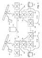
- a satellite communications networkcomprises mobile user terminal equipment 2a,2b; orbiting relay satellites 4a,4b; satellite earth station nodes 6a,6b; satellite system gateway stations 8a,8b; public switched telecommunications networks 10a,10b; and fixed telecommunications terminal equipment 12a,12b.
- Interconnecting the satellite system gateways 8a,8b with the earth station nodes 6a,6b, and interconnecting the nodes 6a,6b with each other,is a dedicated ground-based network comprising channels 14a,14b,14c.
- the satellites 4, earth station nodes 6 and lines 14make up the infrastructure of the satellite communications network, for communication with the mobile terminals 2, and accessible through the gateway stations 8.
- a terminal location database station 15is connected, via a signalling link 60 (e.g. within the channels 14 of the dedicated network) to the gateway station and earth stations 6.
- the PSTNs 10a,10bcomprise, typically, local exchanges 16a,16b to which the fixed terminal equipment 12a,12b is connected via local loops 18a,18b; and international switching centres 20a,20b connectable one to another via transnational links 21 (for example, satellite links or subsea optical fibre cable links).
- transnational links 21for example, satellite links or subsea optical fibre cable links.
- the PSTNs 10a,10b and fixed terminal equipment 12a,12be.g. telephone instruments
- Each mobile terminal apparatusis in communication with a satellite 4 via a full duplex channel (in this embodiment) comprising a downlink channel and an uplink channel, for example (in each case) a TDMA time slot on a particular frequency allocated on initiation of a call, as disclosed in UK patent applications GB 2288913 and GB 2293725.
- the satellites 4 in this embodimentare non geostationary, and thus, periodically, there is handover from one satellite 4 to another.
- a handsetAs shown. Details of the handsets 2a,2b etc do not form part of the present invention, but they may comprise handsets similar to those presently available for use with the GSM system, comprising a digital coder/decoder 30, together with conventional microphone 36, loudspeaker 34, battery 40, control processor (e.g. microprocessor) 35 and keypad components 38, and a radio frequency (RF) interface 32 and antenna 31 suitable for satellite communications.
- a display 39for example a liquid crystal display
- a 'smart card' reader receiving a smart card storing user informationmay be present. Further details are disclosed in our earlier UK application GB 9611411.1 filed on 31 May 1996.
- the coder/decoder (codec) 30 in this embodimentcomprises a low bit rate coder, generating a speech bit stream at around 3.6 kilobits per second, together with a channel coder applying error correcting encoding, to generate an encoded bit stream at a rate of 4.8 kilobits per second.
- the low bit rate codermay, for example, be a linear predictive coder such as a multipulse predictive coder (MPLPC) a code book excited linear predictive coder (CELP), a residual excited linear predictive coder (RELP) or a multiband excitation coder.
- MPLPCmultipulse predictive coder
- CELPcode book excited linear predictive coder
- RELPresidual excited linear predictive coder
- multiband excitation coderAlternatively, it may employ some form of waveform coding such as subband coding.
- the error protection encoding appliedmay employ block codes, BCCH codes, Reed-Solomon codes, turbo codes or convolutional codes.
- the codec 30likewise comprises a corresponding channel decoder (e.g. using Viterbi or soft decision coding) and speech decoder.
- the earth station nodes 6are arranged for communication with the satellites.
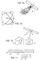
- Each earth station node 6comprises, as shown in Figure 3, a conventional satellite earth station 22 consisting of at least one satellite tracking antenna 24 arranged to track at least one moving satellite 4, RF power amplifiers 26a for supplying a signal to the antenna 24, and 26b for receiving a signal from the antenna 24; and a control unit 28 for storing the satellite ephemeris data, controlling the steering of the antenna 24, and effecting any control of the satellite 4 that may be required (by signalling via the antenna 24 to the satellite 4).
- a conventional satellite earth station 22consisting of at least one satellite tracking antenna 24 arranged to track at least one moving satellite 4, RF power amplifiers 26a for supplying a signal to the antenna 24, and 26b for receiving a signal from the antenna 24; and a control unit 28 for storing the satellite ephemeris data, controlling the steering of the antenna 24, and effecting any control of the satellite 4 that may be required (by signalling via the antenna 24 to the satellite 4).
- the earth station node 6further comprises a mobile satellite switching centre 42 comprising a network switch 44 connected to the trunk links 14 forming part of the dedicated network.
- a multiplexer 46is arranged to receive switched calls from the switch 44 and multiplex them into a composite signal for supply to the amplifier 26 via a low bit-rate voice codec 50.
- the earth station node 6comprises a local store 48 storing details of each mobile terminal equipment 2a within the area served by the satellite 4 with which the node 6 is in communication.
- the local store 48stores, amongst other things, the ID number (e.g. international national mobile subscriber identity or IMSI) of the mobile terminal 2; the status (e.g. local or global) of the terminal; the last known geographical position of the terminal; the satellite 4 through which communication with the mobile terminal is to be attempted and the beam within that satellite; an indication of whether the terminal is or is not available for communication; and an indication of the home gateway 8 of the terminal.
- IMSIinternational national mobile subscriber identity
- the statuse.g. local or global
- the last known geographical position of the terminalthe satellite 4 through which communication with the mobile terminal is to be attempted and the beam within that satellite
- an indication of whether the terminal is or is not available for communicatione.g. authentication data
- other datae.g. authentication data
- the gateway stations 8a,8bcomprise, in this embodiment, commercially available mobile switch centres (MSCs) of the type used in digital mobile cellular radio systems such as GSM systems. They could alternatively comprise a part of an international or other exchange forming one of the PSTNs 10a,10b operating under software control to interconnect the networks 10 with the satellite system trunk lines 14.
- MSCsmobile switch centres
- the gateway stations 8comprise a switch 70 arranged to interconnect incoming PSTN lines from the PSTN 10 with dedicated service lines 14 connected to one or more Earth station nodes 6, under control of a control unit 72.
- the control unit 72is capable of communicating with the data channel 60 connected to the database station 15 via a signalling unit 74, and is arranged to generate data messages in some suitable format (e.g. as packets or ATM cells).
- the satellite system trunk lines 14comprise, in this embodiment, high quality leased lines meeting acceptable minimum criteria for signal degradation and delay. In this embodiment, all the lines 14 comprise terrestrial links.
- the trunk lines 14are preferably dedicated lines, so that the lines 14 form a separate set of physical channels to the networks 10. However, the use of virtual circuits through the networks 10 is not excluded.
- the global database station 15comprises a digital data store 54, a signalling circuit 56, a processor 58 interconnected with the signalling circuit 56 and the store 54, and a signalling link 60 interconnecting the database station 15 with the gateway stations 8 and Earth stations 6 making up satellite system network, for signalling or data message communications.
- the store 54contains, for every subscriber terminal apparatus 2, a record showing the current status of the terminal 2 (whether it is "local” or “global” as will be disclosed in greater detail below); authentication data unique to each mobile terminal for validating the mobile terminal; the "home” gateway station 8 with which the apparatus is registered (to enable billing and other data to be collected at a single point) and the currently active Earth station node 6 with which the apparatus 2 is in communication via the satellite 4.
- the contents of the storeare indicated in Figure 6a.
- the signalling unit 56 and processorare arranged to receive interrogating data messages, via the signalling circuit 60 (which may be a packet switched connection), from gateways 8 or nodes 6, comprising data identifying one of the mobile terminals 2 (for example, the telephone number of the equipment 2), and the processor 58 is arranged to search the store 54 for the status and active earth station node 6 of the terminal 2 and to transmit these in a reply message via the data line 60.
- the signalling circuit 60which may be a packet switched connection
- the processor 58is arranged to search the store 54 for the status and active earth station node 6 of the terminal 2 and to transmit these in a reply message via the data line 60.
- the satellites 4a,4bcomprise generally conventional communications satellites, and may be as disclosed in GB 2288913. Each satellite 4 is arranged to generate an array of beams covering a footprint beneath the satellite, each beam including a number of different frequency channels and time slots, as described in GB 2293725 and illustrated in Figure 7a.
- the satelliteOn each beam, the satellite therefore transmits a set of downlink frequencies.
- the downlink frequencies on adjacent beamsare different, so as to permit frequency re-use between beams.
- Each beamtherefore acts somewhat in the manner of a cell of a conventional terrestrial cellular system.
- each downlink frequencycarries a plurality of time division channels, so that each mobile terminal 2 communicates on a channel comprising a given time slot in a given frequency.
- each beamthere is also provided a common broadcast control channel (equivalent to the broadcast common control channel or BCCH of the GSM system) which occupies at least one of the frequencies for each beam; the frequencies used by the broadcast control channels of the beams are stored within each mobile terminal 2 which is arranged to scan these frequencies repeatedly.
- a common broadcast control channel(equivalent to the broadcast common control channel or BCCH of the GSM system) which occupies at least one of the frequencies for each beam; the frequencies used by the broadcast control channels of the beams are stored within each mobile terminal 2 which is arranged to scan these frequencies repeatedly.
- each broadcast control channel 200comprises interleaved synchronisation periods 202 (labelled “S") and broadcast data periods 204 (labelled “B”).
- Sinterleaved synchronisation periods
- Bbroadcast data periods
- mobile terminals 2are able to acquire time and frequency synchronisation with the broadcast control channel (and hence the other communications channels) prior to reading the broadcast data 204.
- the broadcast dataincludes, amongst other things, a field 206 containing a time value T1 specifying a re-registration interval (as in the GSM system, specified as a number of 6 minute increments) ; and a location area identifier field 208 indicating the number of the beam. For example, there may be 61, 121 or 163 beams each carrying a respective number. The number of the satellite may also be indicated within the location area identifier 208.
- the satellites 4aare arranged in a constellation in sufficient numbers and suitable orbits to cover a substantial area of the globe (preferably to give global coverage) .
- 10 (or more) satellitesmay be provided in two mutually orthogonal intermediate earth orbits (or more)which may be circular, at an altitude of, for example, 10,500 kilometres (6 hour orbits) as shown in Figure 7b.
- equally, however, larger numbers of lower satellitesmay be used, as disclosed in EP 0365885, or other publications relating to the Iridium system, for example.
- each earth station node 6is connectable to gateways 8 on the continent, whilst having in view one or more satellites 4.
- gateways 8there are a significantly larger number of gateways 8 than of earth station nodes 6; on the order of one per country (i.e. over a hundred in total). For larger countries, several gateways 8 may be provided, at different geographical locations, or (where several network operators are permitted in the country) one per PSTN for different PSTN's. Smaller countries may share gateways 8. Gateways 8 may also be provided from terrestrial cellular networks.
- a customer mobile terminal apparatus 2may be registered with one of two distinct statuses; "local” in which the mobile terminal apparatus is permitted only to communicate through one local area, or part of the satellite system network, and "global”, which entitles the apparatus to communicate through any part of the satellite system network.
- the status of each apparatus 2(i.e. "local” or “global") is stored in the record held for the apparatus 2 concerned in the stores 54 and 48.
- the mobile terminal apparatus 2performs an automatic registration process, of the kind well known in the art of cellular terrestrial communications, on various occasions.
- the registration processincludes the broadcasting of a signal identifying the mobile terminal 2 on a common hailing or signalling frequency (such as the BCCH uplink).
- the transmitted signalis picked up by one or more satellites 4. Under normal circumstances, the signal is picked up by multiple satellites 4 and forwarded to the earth station node or nodes 6 with which the satellites 4 are in communication.
- the location updating process itselfis generally similar to that performed within the GSM system, but for clarity a brief description will be given with reference to Figures 8a and 8b.
- a step 1002the control processor 35 of the mobile terminal 2 transmits a location update request signal, which is relayed by at least one satellite 4 to at least one earth station 6.
- the location update requestincludes an ID code indicating the mobile terminal (equivalent to the international mobile subscriber identity (IMSI) or temporary mobile subscriber identity (TMSI) used in the GSM system) and further includes the location area identifer (LAI) received by the mobile terminal 2 on the broadcast control channel (BCCH) to which it has synchronised.
- IMSIinternational mobile subscriber identity
- TMSItemporary mobile subscriber identity
- LAIlocation area identifer
- the earth station 6receives, in a step 1102, the location update request and reads the Doppler shift and relative arrival time of the signal via the or each satellite 4 in a step 1104.
- the earth station node 6determines whether the ID number of the mobile terminal is held within the local store 48.
- the earth station node 6signals to the database station 15 via the signalling link 16 to request details of the mobile terminal.
- the database station 15accesses the database 54 thereof and supplies data concerning the mobile terminal, including in particular authentication data, to the earth station node 6 (step 1108).
- the earth station nodereceives the authentication data in step 1110 and stores the data within the database 48 in step 1112.
- the earth station node 6reads the stored authentication data which comprises, conveniently, the same data as is used in GSM; namely a triplet comprising a random number (RAND); an individual terminal key (K i ) and a signed response (SRES) created by enciphering the random number using a predetermined algorithm (A3) utilising the individual terminal key K i .
- RANDrandom number
- K iindividual terminal key
- SRESsigned response
- the random numberis then transmitted (step 1116) via the satellite 4 to the mobile terminal 2, at which ( Figure 8a, step 1004) it is received.
- step 1006the mobile terminal 2 (which has stored therein the individual terminal key K i and the algorithm A3) uses the received random number to calculate the signed response (SRES) which is then transmitted back to the earth station node 6 via the satellite 4 in step 1008.
- SRESsigned response
- the earth station node 6On receipt thereof ( Figure 8b, step 1118) the earth station node 6 compares the received response with the signed response (SRES) it received from the central database station 15 in step 1120, and if the two do not match then service to the mobile terminal is discontinued, on the assumption that it is not authentic.
- SRESsigned response
- the earth station nodecalculates the rough terrestrial position of the mobile terminal apparatus 2 using the differential arrival times and/or Doppler shifts in the received signal, and knowledge of which beams of which satellites 4 the signal was received through. The position is then stored in the database 48 in step 1124.
- step 1010it is determined (step 1010) whether the authentication has validated the mobile terminal and, if so, normal operation of the terminal continues. If not, the terminal may, for example, indicate on the display 39 that service has been refused.
- the earth station node 6also determines with which satellite 4 and beam to communicate with the mobile terminal 2, and stores the identities of satellite and beam in the database 48.
- the mobile terminal 2scans the communication frequency range, and acquires, at some point, a broadcast control channel (BCCH) of a beam of a satellite 4 (step 1200). Within the signal are recurring, repeated transmissions of a location area indicator (LAI) 208 and a location update interval (T1) 206, both substantially in the multiplexed format known from GSM systems (see Figure 11). Both the LAI and T1 are decoded by the terminal 2 and the update interval T1 is stored (step 1202).
- BCCHbroadcast control channel
- the mobile terminal 2monitors (step 1204) the received control channel (BCCH) continually. Whilst the BCCH is continually available, on each signalling contact received at the mobile terminal 2 from the earth station node 6 via the satellite 4, the control processor 35 resets a first interval timer which forms part of the processor 35.
- BCCHreceived control channel
- the timercontinually counts upwards after each such reset.
- step 1206the processor 35 examines the count on the first timer and determines whether the period T1 has lapsed.
- step 1208the processor determines from the received location area identifier 208 whether a new BCCH has been received. If so, or if the time T1 has expired, in step 1210 the mobile terminal 2 performs the location update process of Figure 8a.
- step 1204the processor 35 resets a second interval timer (again, forming part of the processor 35), which likewise counts continually upwards from each reset.
- Loss of the BCCHmay be due to a deep fade on the radio transmission path or to movement into the area of another satellite, or it may be due to the movement of the user into a building 100 as shown in Figure 10, or to temporary blockage such as a building or other physical obstacle. In such cases, however, the user is very often only temporarily blocked because he or she may move back out of the building or from behind the blockage, or the fade may pass with time.
- step 1212the mobile terminal 2 continually scans the available downlink frequency bands, and on re-acquisition of a broadcast control channel (BCCH), in step 1214, the control processor 35 reads the second timer and determines whether a predetermined time T2 has elapsed. If not, the processor 35 proceeds to execute steps 1206 as described above.
- BCCHbroadcast control channel
- the predetermined time T2is typically of the order of an hour (but could vary, for example, between 15 minutes and 4 hours, or even beyond these limits). Usually, the predetermined time T2 will not be below 5 minutes. With a time period of this order, temporary blockages caused by, for example, driving through a tunnel or passing past a tall block of buildings will have no effect on the location updating operation of the mobile terminal 2.
- step 1214it is determined that the predetermined period T2 has elapsed since the last time at which the mobile terminal 2 was in contact with the earth station node 6, the processor 35 proceeds to step 1210 to perform a location update as described above in relation to Figure 8a.
- the mobile terminal 2On re-acquiring a control channel signal after having been out of contact for more than the predetermined time T2, the mobile terminal 2 immediately attempts to re-register with the land earth station 6, rather than waiting until the elapsing of the first time out period T1.
- a timer(which is continually reset after each registration signal received from a given mobile station 2) is periodically examined (step 1300) and, when the count of the timer exceeds the predetermined registration period T1, in step 1302 the earth station node 6 removes the record of the mobile terminal from the local database station 48, and (step 1304) signals via the signalling channel 60 to the database station 15 that the mobile terminal is unavailable.
- the status of the mobile terminal recordmay be set to "unavailable" and this may be signalled to the database station 15.
- step 1400the unavailability signal is received from the earth station node 6 and in step 1402 it is determined whether the earth station node 6 transmitting the unavailability message is registered as the current active earth station node. If so, the status of the user is set at step 1404 to "unavailable". If not, e.g. because the user has registered elsewhere already) the message is ignored.
- the time out period T1is typically of the order of 24 hours, or may be even longer. Recording the mobile terminal as being unavailable, or deregistering the mobile terminal, or deleting the mobile terminal from the local area store records, advantageously reduces the usage of signalling channels and satellite power in fruitless attempts to reach the mobile terminal, when it may be switched off, inactive through loss of power, located in an inaccessible location or physically transported to a different area.
- the provision of the predetermined time delay T2acts as a filter, allowing the terminal to register or location update only after significant outages (likely to correspond to occasions where unsuccessful contacts with the mobile might have been attempted) have occurred.
- the mobileBy registering immediately after a significant outage, however, the mobile is immediately available in the event that stored messages for the mobile are held within the network and can receive these without delay.
- callsare routed via the satellite and the active earth station, then via the ground network to the gateway station 8 nearest to the terrestrial user.
- the dial numbers allocated to mobile usersmay have "International" prefixes followed by a code corresponding to the satellite service network. Alternatively, they could have a national prefix followed by a regional code assigned to the satellite service.
- Calls between one mobile user and anotherare carried out by directing the signal via a first satellite link down to the active earth station node of the first mobile user, via the ground network to the active earth station node of the second mobile user (which may be, but is not necessarily, the same as that of the first) and then via a second satellite link (which may, but does not need to be via the same satellite) to the second mobile user.
- the earth station 6After the active node data stored in the database station 15 has been used to direct an incoming call to the active earth station node 6 for a given destination mobile terminal, the earth station 6 examines the database 48 to determine the most recently recorded position for the mobile terminal and the most recently recorded satellite and beam.
- a signal(equivalent to the paging signal of GSM) is sent on the downlink control channel (BCCH) on the identified beam of the identified satellite.
- BCCHdownlink control channel
- the earth station node 6examines the position stored in respect of the mobile terminal 2 within the database 48, and determines whether another beam and/or another satellite is also geometrically able to reach the user terminal 6; if so, the paging signal is repeated on the or each such beam and satellite until such contact is made.
- the store 54acts somewhat in the manner of the Home Location Register (HLR) of a GSM terrestrial cellular system, and the store 48 in the manner of the Visiting Location Register (VLR) of GSM; commercially available HLR and/or VLR equipment may therefore be employed for these components, modified as necessary.
- HLRHome Location Register
- VLRVisit Location Register
- the satellite communications systemcorresponds to that of the first embodiment, but with the addition of a messaging centre 300.
- the database station 15routes the call (voice, data or fax) to the messaging centre 300, where it is stored, and records a "message waiting" flag.
- the database station 15sets up a call from the messaging centre 300 to the user so as to forward the message immediately to the user on re-registration thereof with the network.
- a fixed time interval T2is stored at each mobile terminal 2.
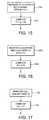
- the broadcast data is 204is expanded as shown in Figure 13 to include an additional field 210 containing a value for T2.
- Each terminal 2is arranged to read the value of T2 and to store it for subsequent use.
- each earth station node 6is able to control the interval at which re-registration is attempted, and hence to control the frequency at which location updating is performed.
- Earth station nodes which are carrying heavy signalling trafficmay thereby increase the period T2 (and hence reduce the frequency of location updating) to reduce the signalling load.
- each mobile terminalis arranged to calculate the time interval T2 as a fraction of the time interval T1 (for example, 4% or 5% of the value of T1).
- the calculated value of T2is stored at step 1205.
- a downlink control channelmay be provided at periodic intervals, so as to allow the mobile terminal 2 to avoid monitoring transmissions for much of the time.
- the mobile terminals 2, the outage duration timecan be surmised by monitoring the number of such paging contacts which should have been received but were not thus received.
- a user terminalmay include a location updating condition corresponding to either the elapsing of the aforementioned predetermined time T2, or the absence of a predetermined number of paging signals, or to some weighted combination of the two.
- the interval T2 forming the predetermined criterion for location updatingmay be calculated by the processor 35 of the mobile terminal 2 in dependence upon the reacquired received signal strength.
- mobile terminal 2may be configured so that the processor 35, at step 1502 measures the re-acquired BCCH signal strength X, and at step 1504 computes the interval T2 as a linear function a+bX, where a and b are constants, so that when the broadcast channel is re-acquired at a relatively low strength immediate location updating is performed.
- the processor 35 of the mobile terminal 2 at step 1602monitors the rate Y at which the control channel is acquired and lost over time.
- de-registrationis performed after the elapse of a predetermined time interval T1.
- de-registrationmay instead be performed on the basis of a predetermined criterion based on other factors.
- the predetermined criterion for de-registrationmay correspond to a predetermined number of failures Z to set up a call to the mobile terminal 2, monitored at step 1702. It may correspond to a combination (for example a weighted linear sum) of a predetermined time T1 and a predetermined number of call failures, as shown at step 1704.
- the numbers of satellites and satellite orbits indicatedare purely exemplary. Smaller numbers of geostationary satellites, or satellites in higher altitude orbits, could be used; or larger numbers of low earth orbit (LEO) satellites could be used. Equally, different numbers of satellites in intermediate orbits could be used.
- LEOlow earth orbit
- TDMAtime division multiple access
- FDMAfrequency division multiple access
- SCPCsingle channel per carrier
- the term “mobile”has been used in the foregoing description to denote the terminals 2, it should be understood that this term is not restricted to handheld or hand-portable terminals, but includes, for example, terminals to be mounted on marine vessels or aircraft, or in terrestrial vehicles. Equally, it is possible to practice the invention with some of the terminals 2 being completely immobile.
- the gateways 8may in fact be comprised within an ISC or exchange or mobile switching centre (MSC) by providing additional operating control programmes performing the function of the gateway.
- MSCmobile switching centre
- the term "global"is used, and it is preferred that the satellite system should cover all or a substantial part of the globe, the invention extends also to similar systems with more restricted coverage (for example of one or more continents).
Landscapes
- Engineering & Computer Science (AREA)
- Physics & Mathematics (AREA)
- Astronomy & Astrophysics (AREA)
- Aviation & Aerospace Engineering (AREA)
- General Physics & Mathematics (AREA)
- Computer Networks & Wireless Communication (AREA)
- Signal Processing (AREA)
- Mobile Radio Communication Systems (AREA)
- Radio Relay Systems (AREA)
- Monitoring And Testing Of Transmission In General (AREA)
Abstract
Description
This invention relates to communications with amobile user, and in particular to such communicationsin which the link to the mobile user is via asatellite or satellites.
US 4189675 proposes a satellite communicationsmethod and apparatus for communicating with mobileusers using a satellite in a predetermined orbit.
EP 0562374 and EP 0568778 are believed todescribe the "Iridium" proposed satellite cellularmobile communication system.
An alternative description of the "Iridium"proposals is given in the paper "The Iridium (TM)system personal communications anytime, any place"J.E. Hatlelid and L. Casey, Proceedings of the ThirdInternational Mobile Satellite Conference IMC 93, 16-18June 1993, pages 285-290.
An alternative proposed satellite cellular systemis described in "The Globalstar Mobile SatelliteSystem for Worldwide Personal Communications", R.A.Weideman, pages 291-296 of the Conference Proceedingsmentioned above. Two alternative access networkschemes, invented by the author of that paper, and believed to have been proposed for use in the proposedGlobalstar system, are described in EP 0536921 andEP 0506255.
GB-A-2295296 and WO-A-96/16488 describe asatellite communications network and in particular theground segment thereof.
Various terrestrial digital cellularcommunications systems are known or proposed. Ofthese, the GSM system is widely known.
In the GSM system, as in other cellular systems,in order to be able to direct incoming calls to auser, it is necessary to be aware of the location ofthe user (so called "mobility management"). In GSM,this is achieved by the provision of two layers ofdatabases; so called "home location registers" (HLRs),and so called "visiting location registers" (VLRs),and by registration and location updating signallingprocesses.
Subscriber data on a given user and/or userterminal is stored in a specific HLR for that user.Each mobile switching centre (MSC) associated with aparticular geographical area has an associated VLR, inwhich are temporarily stored details necessary forcall management of all users currently thought to bewithin the area of that MSC.
Initially, a mobile terminal scans the broadcast common control channels (BCCHs) originating from allbase stations (BSCs) within its reception, andattempts to register with one. The registration takesthe form of an exchange of validation data, asdescribed in "Security aspects and the implementationin the GSM-system", Peter C.J. van der Arend,page 4a,Digital Cellular Radio Conference (DCRC) ConferenceProceedings, 12-14 October 1988, published by DeutcheBundespost, France Telecom and Fernuniversitate.
Specifically, the mobile terminal identifiesitself by transmitting its identity number (IMSI), andthe mobile switching centre (MSC) receiving theidentification signal from the mobile signals the homelocation register (HLR) of the mobile and receivesauthentication data which is stored in the visitinglocation register (VLR).
The MSC then sends an authentication requestsignal to the mobile together with a random number,and the mobile uses the random number together with anindividual stored subscriber authentication key tocalculate a signed response (SRES) which istransmitted back to the MSC.
The MSC then compares the signed response withthe security data including a signed response whichwas supplied by the HLR and, if the two match, themobile terminal is registered as being within the area of the VLR and MSC. On registration, the identity ofthe VLR is stored in the HLR for the mobile terminal.
Subsequently, when incoming calls arrive for themobile terminal, the HLR is accessed to determine theVLR where the mobile is registered and calls are thenrouted to the MSC associated with that VLR.
Even in idle or "sleep" mode, mobile terminalswill continually or periodically scan the broadcastcontrol channels (BCCHs) which they can receive. EachBCCH of a cell carries, amongst other data, a locationarea identifier (LAI) indicating an individual cell ora group of cells within a certain area. When a newlocation area indicator is detected (indicating thatthe mobile terminal has moved into a new area), themobile terminal transmits a location update requestindicating the new LAI.
The exchange of authentication data is repeated,and if the mobile terminal is authenticated the newlocation area indicator is written into the VLR.
Thus, the VLR continually maintains an indicationof which area (and, more specifically, which cell) themobile terminal is within.
A mobile terminal may also move between the areasof two different VLRs.
Similar issues will arise in relation tosatellite communications systems; see, for example, the paper "Study on network issues of medium earthorbit satellite communications systems"; Araki et al,Proceedings of the Third International MobileSatellite Conference IMSC 1993 (JPL publication 93-009),pages 529-534, published by Jet PropulsionLaboratories (1993). In that paper it is describedhow either each land earth station may issue alocation area identifier signal which is carried byspot beams of satellites within the area, or each spotbeam of each satellite may carry a location areaidentifier.
In the GSM system, there is also a signallingprocedure to secure periodic registration from mobilestations, to maintain information on the status ofmobile stations.
The mobile terminal performs periodic re-registrationor location updating using a timer witha time out over a range of between 6 minutes and 25hours 30 minutes, the time out being set in accordancewith a parameter which is optionally transmitted inthe BCCH. The timer value is reset after eachsignalling activity on the radio path. The currenttimer value is stored in non-volatile memory when themobile station powers down. On restoring power, thetime starts running again from the value stored in thememory.
The frequency of such registration updatesaffects the accuracy with which the position of themobile terminal is known, which is important insetting up calls to or from the user. However, everyre-registration or location update uses user terminaland satellite battery power, both of which arepotentially scarce resources. Furthermore, theoverhead of signalling traffic uses scarce networkchannel resources without generating revenue.
Accordingly, the present invention provides amethod of operating a user terminal to providemobility management in a communications system inwhich the user terminal registers data concerning itslocation in a remote management store, the methodincluding: monitoring signals received from thecommunications system in relation to predeterminedcriteria, and upon the monitored signals not meetingthe criteria for more than a predetermined time (T2),transmitting from the user terminal, signals forupdating the location of the user terminal registeredin the management store, when said monitored signalsagain meet said criteria.
A corresponding terminal is also provided.
Other aspects and preferred embodiments of theinvention are as described or claimed hereafter, withadvantages which will be apparent from the following.
Embodiments of the invention will now bedescribed, by way of example only, with reference tothe accompanying drawings, in which:
Referring to Figure 1, a satellite communicationsnetwork according to this embodiment comprises mobileuser terminal equipment relaysatellites earth station nodes system gateway stations telecommunications networks telecommunications terminal equipment
Interconnecting thesatellite system gateways earth station nodes nodes network comprising channels satellites 4,earth station nodes 6andlines 14 make up the infrastructure of thesatellite communications network, for communicationwith themobile terminals 2, and accessible throughthegateway stations 8.
A terminallocation database station 15 isconnected, via a signalling link 60 (e.g. within thechannels 14 of the dedicated network) to the gatewaystation andearth stations 6.
ThePSTNs localexchanges terminalequipment international switching centres PSTNs terminalequipment
Each mobile terminal apparatus is incommunication with asatellite 4 via a full duplexchannel (in this embodiment) comprising a downlinkchannel and an uplink channel, for example (in eachcase) a TDMA time slot on a particular frequencyallocated on initiation of a call, as disclosed in UKpatent applications GB 2288913 and GB 2293725. Thesatellites 4 in this embodiment are non geostationary, and thus, periodically, there is handover from onesatellite 4 to another.
Referring to Figure 2, the mobile terminalequipment of Figure 1 is shown.
One suitable form is a handset, as shown.Details of thehandsets decoder 30,together withconventional microphone 36,loudspeaker 34,battery 40, control processor (e.g.microprocessor) 35 andkeypad components 38, and aradio frequency (RF)interface 32 andantenna 31suitable for satellite communications. Preferably adisplay 39 (for example a liquid crystal display) isalso provided. A 'smart card' reader receiving asmart card storing user information may be present.Further details are disclosed in our earlier UKapplication GB 9611411.1 filed on 31 May 1996.
The coder/decoder (codec) 30 in this embodimentcomprises a low bit rate coder, generating a speechbit stream at around 3.6 kilobits per second, togetherwith a channel coder applying error correctingencoding, to generate an encoded bit stream at a rateof 4.8 kilobits per second. The low bit rate coder may, for example, be a linear predictive coder such asa multipulse predictive coder (MPLPC) a code bookexcited linear predictive coder (CELP), a residualexcited linear predictive coder (RELP) or a multibandexcitation coder. Alternatively, it may employ someform of waveform coding such as subband coding.
The error protection encoding applied may employblock codes, BCCH codes, Reed-Solomon codes, turbocodes or convolutional codes. Thecodec 30 likewisecomprises a corresponding channel decoder (e.g. usingViterbi or soft decision coding) and speech decoder.
Theearth station nodes 6 are arranged forcommunication with the satellites.
Eachearth station node 6 comprises, as shown inFigure 3, a conventionalsatellite earth station 22consisting of at least onesatellite tracking antenna 24 arranged to track at least one movingsatellite 4,RF power amplifiers 26a for supplying a signal to theantenna antenna 24; and acontrol unit 28 for storing thesatellite ephemeris data, controlling the steering oftheantenna 24, and effecting any control of thesatellite 4 that may be required (by signalling viatheantenna 24 to the satellite 4).
Theearth station node 6 further comprises a mobilesatellite switching centre 42 comprising anetwork switch 44 connected to the trunk links 14forming part of the dedicated network. Amultiplexer 46 is arranged to receive switched calls from theswitch 44 and multiplex them into a composite signalfor supply to the amplifier 26 via a low bit-ratevoice codec 50. Finally, theearth station node 6comprises alocal store 48 storing details of eachmobile terminal equipment 2a within the area served bythesatellite 4 with which thenode 6 is incommunication.
Referring to Figure 6b, thelocal store 48stores, amongst other things, the ID number (e.g.international national mobile subscriber identity orIMSI) of themobile terminal 2; the status (e.g. localor global) of the terminal; the last knowngeographical position of the terminal; thesatellite 4 through which communication with the mobile terminalis to be attempted and the beam within that satellite;an indication of whether the terminal is or is notavailable for communication; and an indication of thehome gateway 8 of the terminal. Naturally, other data(e.g. authentication data) may also be stored.
Referring to Figure 4, thegateway stations PSTNs networks 10 with the satellite systemtrunk lines 14.
Thegateway stations 8 comprise aswitch 70arranged to interconnect incoming PSTN lines from thePSTN 10 withdedicated service lines 14 connected toone or moreEarth station nodes 6, under control of acontrol unit 72. The control unit 72 is capable ofcommunicating with thedata channel 60 connected tothedatabase station 15 via asignalling unit 74, andis arranged to generate data messages in some suitableformat (e.g. as packets or ATM cells).
Also provided in thegateway stations 8 is astore 76 storing billing, service and otherinformation relating to thosemobile terminals 2 forwhich thegateway station 8 is the home gatewaystation. Data is written to thestore 76 by thecontrol unit 72 after being received via thesignalling unit 74 orswitch 70, from thePSTN 10 ortheEarth station nodes 6 making up the satellitenetwork.
The satellitesystem trunk lines 14 comprise, in this embodiment, high quality leased lines meetingacceptable minimum criteria for signal degradation anddelay. In this embodiment, all thelines 14 compriseterrestrial links. Thetrunk lines 14 are preferablydedicated lines, so that thelines 14 form a separateset of physical channels to thenetworks 10. However,the use of virtual circuits through thenetworks 10 isnot excluded.
Referring to Figure 5 theglobal database station 15 comprises adigital data store 54, asignallingcircuit 56, aprocessor 58 interconnected with thesignalling circuit 56 and thestore 54, and asignalling link 60 interconnecting thedatabasestation 15 with thegateway stations 8 andEarthstations 6 making up satellite system network, forsignalling or data message communications.
Thestore 54 contains, for everysubscriberterminal apparatus 2, a record showing the currentstatus of the terminal 2 (whether it is "local" or"global" as will be disclosed in greater detailbelow); authentication data unique to each mobileterminal for validating the mobile terminal; the"home"gateway station 8 with which the apparatus isregistered (to enable billing and other data to becollected at a single point) and the currently activeEarth station node 6 with which theapparatus 2 is incommunication via thesatellite 4. The contents ofthe store are indicated in Figure 6a.
The signallingunit 56 and processor are arrangedto receive interrogating data messages, via thesignalling circuit 60 (which may be a packet switchedconnection), fromgateways 8 ornodes 6, comprisingdata identifying one of the mobile terminals 2 (forexample, the telephone number of the equipment 2), andtheprocessor 58 is arranged to search thestore 54for the status and activeearth station node 6 of theterminal 2 and to transmit these in a reply messagevia thedata line 60.
Thesatellites satellite 4 is arrangedto generate an array of beams covering a footprintbeneath the satellite, each beam including a number ofdifferent frequency channels and time slots, asdescribed in GB 2293725 and illustrated in Figure 7a.
On each beam, the satellite therefore transmitsa set of downlink frequencies. The downlinkfrequencies on adjacent beams are different, so as topermit frequency re-use between beams. Each beamtherefore acts somewhat in the manner of a cell of a conventional terrestrial cellular system.
In this embodiment each downlink frequencycarries a plurality of time division channels, so thateachmobile terminal 2 communicates on a channelcomprising a given time slot in a given frequency.
Within each beam there is also provided a commonbroadcast control channel (equivalent to the broadcastcommon control channel or BCCH of the GSM system)which occupies at least one of the frequencies foreach beam; the frequencies used by the broadcastcontrol channels of the beams are stored within eachmobile terminal 2 which is arranged to scan thesefrequencies repeatedly.
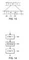
Referring to Figure 11, eachbroadcast controlchannel 200 comprises interleaved synchronisationperiods 202 (labelled "S") and broadcast data periods204 (labelled "B"). Thus,mobile terminals 2 are ableto acquire time and frequency synchronisation with thebroadcast control channel (and hence the othercommunications channels) prior to reading thebroadcast data 204.
The broadcast data includes, amongst otherthings, afield 206 containing a time value T1specifying a re-registration interval (as in the GSMsystem, specified as a number of 6 minute increments) ;and a locationarea identifier field 208 indicating the number of the beam. For example, there may be 61,121 or 163 beams each carrying a respective number.The number of the satellite may also be indicatedwithin thelocation area identifier 208.
Thesatellites 4a are arranged in a constellationin sufficient numbers and suitable orbits to cover asubstantial area of the globe (preferably to giveglobal coverage) . For example 10 (or more) satellitesmay be provided in two mutually orthogonalintermediate earth orbits (or more)which may becircular, at an altitude of, for example, 10,500kilometres (6 hour orbits) as shown in Figure 7b.Equally, however, larger numbers of lower satellitesmay be used, as disclosed in EP 0365885, or otherpublications relating to the Iridium system, forexample.
With the number of satellites mentioned below,there may typically be 12earth station nodes 6, twofor each continent. In this manner, eachearthstation node 6 is connectable togateways 8 on thecontinent, whilst having in view one ormoresatellites 4.
In this embodiment there are a significantlylarger number ofgateways 8 than ofearth stationnodes 6; on the order of one per country (i.e. over a hundred in total). For larger countries,severalgateways 8 may be provided, at different geographicallocations, or (where several network operators arepermitted in the country) one per PSTN for differentPSTN's. Smaller countries may sharegateways 8.Gateways 8 may also be provided from terrestrialcellular networks.
A customer mobileterminal apparatus 2 may beregistered with one of two distinct statuses; "local"in which the mobile terminal apparatus is permittedonly to communicate through one local area, or part ofthe satellite system network, and "global", whichentitles the apparatus to communicate through any partof the satellite system network.
The status of each apparatus 2 (i.e. "local" or"global") is stored in the record held for theapparatus 2 concerned in thestores
The operation will now be described in greaterdetail.
The mobileterminal apparatus 2 performs anautomatic registration process, of the kind well knownin the art of cellular terrestrial communications, onvarious occasions. As is conventional, theregistration process includes the broadcasting of asignal identifying themobile terminal 2 on a common hailing or signalling frequency (such as the BCCHuplink).
The transmitted signal is picked up by one ormore satellites 4. Under normal circumstances, thesignal is picked up bymultiple satellites 4 andforwarded to the earth station node ornodes 6 withwhich thesatellites 4 are in communication.
The location updating process itself is generallysimilar to that performed within the GSM system, butfor clarity a brief description will be given withreference to Figures 8a and 8b.
Referring to Figure 8a, in astep 1002 thecontrol processor 35 of themobile terminal 2transmits a location update request signal, which isrelayed by at least onesatellite 4 to at least oneearth station 6.
The location update request includes an ID codeindicating the mobile terminal (equivalent to theinternational mobile subscriber identity (IMSI) ortemporary mobile subscriber identity (TMSI) used inthe GSM system) and further includes the location areaidentifer (LAI) received by themobile terminal 2 onthe broadcast control channel (BCCH) to which it hassynchronised.
Referring to Figure 8b, theearth station 6receives, in astep 1102, the location update request and reads the Doppler shift and relative arrival timeof the signal via the or eachsatellite 4 in astep 1104.
In astep 1106, theearth station node 6determines whether the ID number of the mobileterminal is held within thelocal store 48.
If details of the mobile terminal are not alreadystored in thedatabase 48, theearth station node 6signals to thedatabase station 15 via the signallinglink 16 to request details of the mobile terminal.
Thedatabase station 15 accesses thedatabase 54thereof and supplies data concerning the mobileterminal, including in particular authentication data,to the earth station node 6 (step 1108). The earthstation node receives the authentication data instep 1110 and stores the data within thedatabase 48 instep 1112.
Instep 1114, theearth station node 6 reads thestored authentication data which comprises,conveniently, the same data as is used in GSM; namelya triplet comprising a random number (RAND); anindividual terminal key (Ki) and a signed response(SRES) created by enciphering the random number usinga predetermined algorithm (A3) utilising theindividual terminal key Ki.
The random number is then transmitted (step 1116) via thesatellite 4 to themobile terminal 2, at which(Figure 8a, step 1004) it is received.
Instep 1006, the mobile terminal 2 (which hasstored therein the individual terminal key Ki and thealgorithm A3) uses the received random number tocalculate the signed response (SRES) which is thentransmitted back to theearth station node 6 via thesatellite 4 instep 1008.
On receipt thereof (Figure 8b, step 1118) theearth station node 6 compares the received responsewith the signed response (SRES) it received from thecentral database station 15 instep 1120, and if thetwo do not match then service to the mobile terminalis discontinued, on the assumption that it is notauthentic.
If the two do match, then instep 1122, the earthstation node calculates the rough terrestrial positionof the mobileterminal apparatus 2 using thedifferential arrival times and/or Doppler shifts inthe received signal, and knowledge of which beams ofwhichsatellites 4 the signal was received through.The position is then stored in thedatabase 48 instep 1124.
At themobile terminal 2, it is determined (step1010) whether the authentication has validated themobile terminal and, if so, normal operation of the terminal continues. If not, the terminal may, forexample, indicate on thedisplay 39 that service hasbeen refused.
Theearth station node 6 also determines withwhichsatellite 4 and beam to communicate with themobile terminal 2, and stores the identities ofsatellite and beam in thedatabase 48.
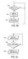
Referring to Figure 9, the conditions under whichlocation updating is performed will now be describedin greater detail.
Initially, themobile terminal 2 scans thecommunication frequency range, and acquires, at somepoint, a broadcast control channel (BCCH) of a beam ofa satellite 4 (step 1200). Within the signal arerecurring, repeated transmissions of a location areaindicator (LAI) 208 and a location update interval(T1) 206, both substantially in the multiplexed formatknown from GSM systems (see Figure 11). Both the LAIand T1 are decoded by theterminal 2 and the updateinterval T1 is stored (step 1202).
Themobile terminal 2 monitors (step 1204) thereceived control channel (BCCH) continually. Whilstthe BCCH is continually available, on each signallingcontact received at themobile terminal 2 from theearth station node 6 via thesatellite 4, thecontrolprocessor 35 resets a first interval timer which forms part of theprocessor 35.
The timer continually counts upwards after eachsuch reset.
Periodically (step 1206), theprocessor 35examines the count on the first timer and determineswhether the period T1 has lapsed.
If not (step 1208), the processor determines fromthe receivedlocation area identifier 208 whether anew BCCH has been received. If so, or if the time T1has expired, instep 1210 themobile terminal 2performs the location update process of Figure 8a.
If, instep 1204, the BCCH is determined not tobe available, theprocessor 35 resets a secondinterval timer (again, forming part of the processor35), which likewise counts continually upwards fromeach reset.
Loss of the BCCH may be due to a deep fade on theradio transmission path or to movement into the areaof another satellite, or it may be due to the movementof the user into abuilding 100 as shown in Figure 10,or to temporary blockage such as a building or otherphysical obstacle. In such cases, however, the useris very often only temporarily blocked because he orshe may move back out of the building or from behindthe blockage, or the fade may pass with time.
Instep 1212, themobile terminal 2 continually scans the available downlink frequency bands, and onre-acquisition of a broadcast control channel (BCCH),instep 1214, thecontrol processor 35 reads thesecond timer and determines whether a predeterminedtime T2 has elapsed. If not, theprocessor 35proceeds to executesteps 1206 as described above.
The predetermined time T2 is typically of theorder of an hour (but could vary, for example, between15 minutes and 4 hours, or even beyond these limits).Usually, the predetermined time T2 will not be below5 minutes. With a time period of this order,temporary blockages caused by, for example, drivingthrough a tunnel or passing past a tall block ofbuildings will have no effect on the location updatingoperation of themobile terminal 2.
Where, instep 1214, it is determined that thepredetermined period T2 has elapsed since the lasttime at which themobile terminal 2 was in contactwith theearth station node 6, theprocessor 35proceeds to step 1210 to perform a location update asdescribed above in relation to Figure 8a.
Thus, on re-acquiring a control channel signalafter having been out of contact for more than thepredetermined time T2, themobile terminal 2immediately attempts to re-register with thelandearth station 6, rather than waiting until the elapsing of the first time out period T1.
Referring to Figure 9b, at theearth station node 6, a timer (which is continually reset after eachregistration signal received from a given mobilestation 2) is periodically examined (step 1300) and,when the count of the timer exceeds the predeterminedregistration period T1, instep 1302 theearth stationnode 6 removes the record of the mobile terminal fromthelocal database station 48, and (step 1304) signalsvia the signallingchannel 60 to thedatabase station 15 that the mobile terminal is unavailable.Alternatively, the status of the mobile terminalrecord may be set to "unavailable" and this may besignalled to thedatabase station 15.
At thedatabase station 15, referring to Figure9c, instep 1400 the unavailability signal is receivedfrom theearth station node 6 and instep 1402 it isdetermined whether theearth station node 6transmitting the unavailability message is registeredas the current active earth station node. If so, thestatus of the user is set atstep 1404 to"unavailable". If not, e.g. because the user hasregistered elsewhere already) the message is ignored.
The time out period T1 is typically of the orderof 24 hours, or may be even longer. Recording themobile terminal as being unavailable, or deregistering the mobile terminal, or deleting themobile terminal from the local area store records,advantageously reduces the usage of signallingchannels and satellite power in fruitless attempts toreach the mobile terminal, when it may be switchedoff, inactive through loss of power, located in aninaccessible location or physically transported to adifferent area.
It will thus be seen that the above describedembodiment, on the one hand, enables the avoidance ofwasted resources by attempts to contact uncontactablemobile terminals. On the other hand, mobile batterypower and network resources are also conserved by theavoidance of automatic re-registration after everyoutage (i.e. every occasion on which contact with thenetwork is lost).
The provision of the predetermined time delay T2acts as a filter, allowing the terminal to register orlocation update only after significant outages (likelyto correspond to occasions where unsuccessful contactswith the mobile might have been attempted) haveoccurred.
By registering immediately after a significantoutage, however, the mobile is immediately availablein the event that stored messages for the mobile areheld within the network and can receive these without delay.
The processes of routing calls to and from mobileterminal apparatus 2 are generally described inGB-A-2295296 or WO96/16488, both of which are herebyincorporated fully by reference. Briefly, for a localuser outside its area, a call placed to the user orfrom the user is referred to thedatabase station 15which determines that the user is outside of its areaand thereafter does not process the call. For a localuser which is inside its area, in the preferredembodiment described in the above referenced Britishand International application, calls to or from theuser are set up over the satellite link, via theactive earth station 6, the ground network, and theinternational public switch telephone network (PSTN)from thenearest gateway 8 to the terrestrial user.
For global users, calls are routed via thesatellite and the active earth station, then via theground network to thegateway station 8 nearest to theterrestrial user.
The dial numbers allocated to mobile users mayhave "International" prefixes followed by a codecorresponding to the satellite service network.Alternatively, they could have a national prefixfollowed by a regional code assigned to the satellite service.
Calls between one mobile user and another arecarried out by directing the signal via a firstsatellite link down to the active earth station nodeof the first mobile user, via the ground network tothe active earth station node of the second mobileuser (which may be, but is not necessarily, the sameas that of the first) and then via a second satellitelink (which may, but does not need to be via the samesatellite) to the second mobile user.
After the active node data stored in thedatabasestation 15 has been used to direct an incoming call tothe activeearth station node 6 for a givendestination mobile terminal, theearth station 6examines thedatabase 48 to determine the mostrecently recorded position for the mobile terminal andthe most recently recorded satellite and beam.
A signal (equivalent to the paging signal of GSM)is sent on the downlink control channel (BCCH) on theidentified beam of the identified satellite. If noresponse is received from themobile terminal 2, theearth station node 6 examines the position stored inrespect of themobile terminal 2 within thedatabase 48, and determines whether another beam and/or anothersatellite is also geometrically able to reach theuserterminal 6; if so, the paging signal is repeated on the or each such beam and satellite until such contactis made.
Thestore 54 acts somewhat in the manner of theHome Location Register (HLR) of a GSM terrestrialcellular system, and thestore 48 in the manner of theVisiting Location Register (VLR) of GSM; commerciallyavailable HLR and/or VLR equipment may therefore beemployed for these components, modified as necessary.
Referring to Figure 12, in the second embodimentthe satellite communications system corresponds tothat of the first embodiment, but with the addition ofamessaging centre 300.
When an attempt is made to place a call to a userwhose status is recorded as unavailable, thedatabasestation 15 routes the call (voice, data or fax) to themessaging centre 300, where it is stored, and recordsa "message waiting" flag.
When the status of the user next changes to"available", thedatabase station 15 sets up a callfrom themessaging centre 300 to the user so as toforward the message immediately to the user on re-registrationthereof with the network.
In the first embodiment, a fixed time interval T2is stored at eachmobile terminal 2. In this embodiment, however, the broadcast data is 204 isexpanded as shown in Figure 13 to include anadditional field 210 containing a value for T2. Eachterminal 2 is arranged to read the value of T2 and tostore it for subsequent use. Thus, eachearth stationnode 6 is able to control the interval at which re-registrationis attempted, and hence to control thefrequency at which location updating is performed.Earth station nodes which are carrying heavysignalling traffic may thereby increase the period T2(and hence reduce the frequency of location updating)to reduce the signalling load.
The third embodiment has the disadvantages thatit is not fully compatible with the GSM signallingformat, and that additional capacity on the downlinkbroadcast control channel is required. Accordingly,in this embodiment, as shown asstep 1203 in Figure 14each mobile terminal is arranged to calculate the timeinterval T2 as a fraction of the time interval T1 (forexample, 4% or 5% of the value of T1). The calculatedvalue of T2 is stored atstep 1205. Thus, when underexceptional circumstancesearth station nodes 6 wishto reduce the frequency of re-registration, they canalter the value of the interval T1 to make it longer.This requires no modifications to the GSM signalling protocols.
The above embodiments describe a continuousdownlink transmission channel. However, in othermobile communications systems, rather than provide acontinuously monitored downlink signal, a downlinkcontrol channel may be provided at periodic intervals,so as to allow themobile terminal 2 to avoidmonitoring transmissions for much of the time.
In this case, themobile terminals 2, the outageduration time can be surmised by monitoring the numberof such paging contacts which should have beenreceived but were not thus received.
This embodiment may be combined with the firstembodiment in systems where both a common broadcastchannel and continuous paging messages are provided;thus, a user terminal may include a location updatingcondition corresponding to either the elapsing of theaforementioned predetermined time T2, or the absenceof a predetermined number of paging signals, or tosome weighted combination of the two.
In the above described embodiments, detection ofpresence or absence of a broadcast channel isemployed. However, it is also possible to take intoaccount the received signal strength of the broadcast channel. Thus, for example, where the broadcastchannel is lost and then re-acquired, the interval T2forming the predetermined criterion for locationupdating may be calculated by theprocessor 35 of themobile terminal 2 in dependence upon the reacquiredreceived signal strength.
For example, as shown in Figure 15,mobileterminal 2 may be configured so that theprocessor 35,atstep 1502 measures the re-acquired BCCH signalstrength X, and atstep 1504 computes the interval T2as a linear function a+bX, where a and b areconstants, so that when the broadcast channel is re-acquiredat a relatively low strength immediatelocation updating is performed.
This may be useful where it is assumed that a lowre-acquisition strength corresponds to a likelihoodthat the broadcast channel may shortly be lost again.
In the preceding embodiments, no account is takenof the history of signal loss and acquisition. Inthis embodiment, however, as shown in Figure 16, theprocessor 35 of themobile terminal 2 atstep 1602monitors the rate Y at which the control channel isacquired and lost over time. The period T2 is computedas a function of the rate Y, i.e. T2 = f(Y). If, forexample, the control channel has been lost for 10 successive intervals over the previous hour then thetime interval T2 may be reduced by a predeterminedincrement, so as to increase the likelihood of re-registration.
In the above described embodiments, de-registrationis performed after the elapse of apredetermined time interval T1. However, de-registrationmay instead be performed on the basis ofa predetermined criterion based on other factors.
For example, as shown in Figure 17 thepredetermined criterion for de-registration maycorrespond to a predetermined number of failures Z toset up a call to themobile terminal 2, monitored atstep 1702. It may correspond to a combination (forexample a weighted linear sum) of a predetermined timeT1 and a predetermined number of call failures, asshown atstep 1704.
Naturally, this embodiment and all the otherabove described embodiments may be combined in anydesired sub-combinations.
It will be clear from the foregoing that theabove described embodiment is merely one way ofputting the invention into effect. Many otheralternatives will be apparent to the skilled person and are within the scope of the present invention.
For example, the numbers of satellites andsatellite orbits indicated are purely exemplary.Smaller numbers of geostationary satellites, orsatellites in higher altitude orbits, could be used;or larger numbers of low earth orbit (LEO) satellitescould be used. Equally, different numbers ofsatellites in intermediate orbits could be used.
Although TDMA has been mentioned as a suitableaccess protocol, the present invention is fullyapplicable to other access protocols, such as codedivision multiple access (CDMA) or frequency divisionmultiple access (FDMA) or even single channel percarrier (SCPC).
Equally, whilst the principles of the presentinvention are envisaged above as being applied tosatellite communication systems, the possibility ofthe extension of the invention to othercommunications systems (e.g. digital terrestrialcellular systems such as GSM) is not excluded.
Although, for the sake of convenience, the term"mobile" has been used in the foregoing description todenote theterminals 2, it should be understood thatthis term is not restricted to handheld or hand-portableterminals, but includes, for example,terminals to be mounted on marine vessels or aircraft, or in terrestrial vehicles. Equally, it is possibleto practice the invention with some of theterminals 2 being completely immobile.
Instead of providing a singlecentral databasestation 15 storing details of allterminal equipment 2, similar details could be stored at thehome gateway 8 for all terminal equipment to register with thathome gateway 8.
In the foregoing, thegateways 8 may in fact becomprised within an ISC or exchange or mobileswitching centre (MSC) by providing additionaloperating control programmes performing the functionof the gateway.
In the foregoing, dedicated ground networks lineshave been described, and are preferred. However, useof PSTN or PLMN links is not excluded where, forexample, leased lines are unavailable or wheretemporary additional capacity is required to cope withtraffic conditions.
It will naturally be clear that the stores withinthegateways 8 need not be physically co-located withother components thereof, provided they are connectedvia a signalling link.
Whilst, in the foregoing, the term "global" isused, and it is preferred that the satellite systemshould cover all or a substantial part of the globe, the invention extends also to similar systems withmore restricted coverage (for example of one or morecontinents).
It will be understood that the geographicallocations of the various components of the inventionare not important, and that different parts of thesystem of the above embodiments may be provided indifferent national jurisdictions. For the avoidanceof doubt, the present invention extends to any part orcomponent of telecommunications apparatus or systemswhich contributes to the inventive concept.
The foregoing, and all other variants,embodiments, modifications or improvements to theinvention are intended to be comprised within thepresent invention.
Claims (32)
- A method of operating a user terminal to providemobility management in a communications system inwhich the user terminal registers data concerning itslocation in a remote management store, the methodincluding:monitoring signals received from thecommunications system in relation to predeterminedcriteria, andupon the monitored signals not meeting thecriteria for more than a predetermined time (T2),transmitting from the user terminal, signals forupdating the location of the user terminal registeredin the management store, when said monitored signalsagain meet said criteria.
- A method according to claim 1, wherein themonitoring includes monitoring the acquisition andloss of reception of a given channel (BCCH) broadcastfrom the communications system.
- A method according to claim 1 or 2 in which themonitoring comprises monitoring the received signalquality on the given channel (BCCH).
- A method according to claim 1 or 2 in which themonitoring comprises monitoring the received signalstrength of the given channel (BCCH).
- A method according to claim 1 or 2 in which themonitoring comprises monitoring the rate at whichlosses of the given channel (BCCH) occur over time.
- A method according to any preceding claim, inwhich the monitoring comprises monitoring theoccurrence of a received sequence of paging signals.
- A method according to any preceding claimincluding periodically transmitting from the userterminal, signals for updating the location of theuser terminal as registered in the management store,after a predetermined location update interval (T1).
- A method according to claim 7 wherein saidlocation update interval (T1) is longer than saidpredetermined time (T2).
- A method according to any preceding claimincluding transmitting from the user terminal, signalsfor updating the location of the user terminal asregistered in the management store, in response to signals (BCCH, LAI) received from the satellite thatindicate a change in the terminal's location.
- A method of mobility management in acommunications system wherein a user terminal (2) isoperated according to any preceding claim such thatthe user terminal registers data concerning itslocation in a remote management store.
- A method according to claim 11 further comprisingcausing the management store to indicateunavailability of the user terminal (2) if noregistration of data concerning its location occurswithin a given time (T1).
- A method according to claim 11 or 12 in which thecommunications system is a satellite communicationssystem including one or more satellites (4).
- A method according to claim 13 in which thesystem includes a constellation of satellites in non-geostationaryorbits.
- A method according to claim 14 in which thesatellites are medium earth orbits.
- A method according to claim 15 in which theorbits are 6 hour orbits.
- A method according to any one of claims 10 to 15in which there are provided a plurality of saidmanagement stores (48) each associated with acorresponding switching node (6), including storingthe stores (48) data relating to more than one saiduser terminal (2) in a service area for the respectiveswitching node (6).
- A method according to claim 16 in which there isprovided at least one home store (54), and the methodincluding storing information relating to the userterminal in the home store (2) regardless of thelocation of that user terminal.
- A method according to claim 17 including storingin the home store (54), information relating toidentity of the switching node (6) within the servicearea of which the user terminal (2) is located, inrelation to the or each user terminal (2).
- A method according to any of claims 17 to 19 inwhich the or each management store (48) is arranged tostore data defining the approximate position on the earth's surface of a user terminal (2).
- User terminal apparatus (2) for a mobilecommunications system, said apparatus being arrangedto operate within the method of any preceding claim.
- A user terminal to provide mobility management ina communications system in which the user terminalregisters data concerning its location in a remotemanagement store, including:a monitoring device operative to monitor signalsreceived from the communications system in relation topredetermined criteria, anda transmitter operative to transmit, upon themonitored signals not meeting the criteria for morethan a predetermined time (T2), signals for updatingthe location of the user terminal registered in themanagement store, when said monitored signals againmeet said criteria.
- A user terminal according to claim 21 includinga timer for timing said predetermined time (T2)
- A user terminal according to claim 21 or 22wherein the monitoring device is operative to monitorthe acquisition and loss of reception of a given channel (BCCH) broadcast from the communicationssystem.
- A user terminal according to any one of claims 22to 23 in which the monitoring comprises monitoring thereceived signal quality on the given channel (BCCH).
- A user terminal according to claim 21 or 22wherein the monitoring device is operative to monitorthe received signal strength of the given channel(BCCH).
- A user terminal according to claim 21 or 22wherein the monitoring device is operative to monitorthe rate at which losses of the given channel (BCCH)occur over time.
- A user terminal according to claim 21 or 22wherein the monitoring device is operative to monitorthe occurrence of a received sequence of pagingsignals.
- A user terminal according to any one of claims 21to 27 wherein the transmitter is operative totransmit periodically from the user terminal, signalsfor updating the location of the user terminal as registered in the management store, after apredetermined location update interval (T1).
- A user terminal according to claim 28 includinga timer for defining said location update interval(T1) to be longer than said predetermined time (T2).
- A mobile satellite communications systemcomprising at least one mobile terminal (2), at leastone ground station (6), at least one relay satellite(4) interconnecting said user terminal (2) and saidground station (6), and a management store (48)associated with said ground station (6), in which theuser terminal (2) is configured to initiateregistration signalling with said store (48),characterised in that the user terminal (2) isarranged to initiate said registration signalling whenreception conditions relating to a downlink channelrelayed via said satellite (4) become unsatisfactoryover a given time not less than a predeterminedminimum value and then return to a satisfactorycondition.
- A method of operating a user terminal to providemobility management in a communications system inwhich the user terminal registers data concerning its location in a remote management store, the methodincluding:monitoring signals received in a given channelfrom the communications system in relation topredetermined criteria,timing the duration of periods when the monitoredsignals do not meet the criteria, andtransmitting from the user terminal, signalsfor updating the location of the user terminalregistered in the management store, when saidmonitored signals in said channel again meet saidcriteria, in response to the timed duration for whichthe monitored signals do not meet the criteria, beingnot less than a predetermined time (T2).
- A method of operating a user terminal to providemobility management in a communications system inwhich the user terminal registers data concerning itslocation in a remote management store, the methodincluding:monitoring signals received in a given channelfrom the communications system in relation topredetermined criteria, andupon the monitored signals not meeting thecriteria, transmitting from the user terminal, signalsfor updating the location of the user terminal registered in the management store, when saidmonitored signals in said channel again meet saidcriteria.
Applications Claiming Priority (2)
| Application Number | Priority Date | Filing Date | Title |
|---|---|---|---|
| GB9618737AGB2317303B (en) | 1996-09-09 | 1996-09-09 | Communications apparatus and method |
| GB9618737 | 1996-09-09 |
Publications (2)
| Publication Number | Publication Date |
|---|---|
| EP0828353A2true EP0828353A2 (en) | 1998-03-11 |
| EP0828353A3 EP0828353A3 (en) | 1999-01-13 |
Family
ID=10799609
Family Applications (1)
| Application Number | Title | Priority Date | Filing Date |
|---|---|---|---|
| EP97306954AWithdrawnEP0828353A3 (en) | 1996-09-09 | 1997-09-08 | Registration method and apparatus in mobile communication system |
Country Status (4)
| Country | Link |
|---|---|
| US (1) | US6201967B1 (en) |
| EP (1) | EP0828353A3 (en) |
| JP (1) | JPH10164647A (en) |
| GB (1) | GB2317303B (en) |
Cited By (9)
| Publication number | Priority date | Publication date | Assignee | Title |
|---|---|---|---|---|
| WO1999057821A1 (en)* | 1998-05-01 | 1999-11-11 | Ericsson, Inc. | Methods for determining registration at a satellite communications system and related user terminals and systems |
| EP0964531A1 (en)* | 1998-06-12 | 1999-12-15 | ICO Services Ltd. | Cell selection in a mobile satellite system using time delay and Doppler shifts to determine the position of the user |
| WO1999060810A3 (en)* | 1998-05-20 | 1999-12-29 | Inmarsat Ltd | Satellite communication method and apparatus |
| WO2000019639A1 (en)* | 1998-09-30 | 2000-04-06 | Qualcomm Incorporated | Apparatus and method for sending common information on common data channels |
| WO2000033483A1 (en)* | 1998-11-30 | 2000-06-08 | Hughes Electronics Corporation | A method for implementing a terminal-to-terminal call with an optimal use of radio resources in a mobile satellite system |
| US7177939B2 (en)* | 1999-05-14 | 2007-02-13 | Cingular Wireless Ii, Llc | Aircraft data communications services for users |
| US7194523B2 (en) | 1998-09-09 | 2007-03-20 | Cingular Wireless Ii, Llc | Method and apparatus for data communication utilizing the North American Terrestrial System |
| CN103763017A (en)* | 2014-01-17 | 2014-04-30 | 航天数字传媒有限公司 | Data receiving method for user terminal of satellite |
| US11533103B2 (en) | 2021-01-07 | 2022-12-20 | Hughes Network Systems, Llc | Compensation for attenuation of carrier power by a transmission path |
Families Citing this family (109)
| Publication number | Priority date | Publication date | Assignee | Title |
|---|---|---|---|---|
| GB2319696B (en)* | 1996-11-20 | 2001-08-01 | Internat Mobile Satellite Orga | Communication method and apparatus |
| FI105638B (en)* | 1997-05-14 | 2000-09-15 | Nokia Networks Oy | Method for assessing the capacity requirement in different parts of a cellular radio system |
| US6738621B1 (en)* | 1997-12-05 | 2004-05-18 | Koninklijke Kpn N.V. | Exchange of communication traffic in a satellite communication system |
| US7293107B1 (en)* | 1998-10-09 | 2007-11-06 | Netmotion Wireless, Inc. | Method and apparatus for providing mobile and other intermittent connectivity in a computing environment |
| US6507926B1 (en)* | 1999-03-16 | 2003-01-14 | Trw Inc. | Mitigation of false co-channel uplink reception in a processing satellite communication system using stagger |
| US7174127B2 (en) | 1999-08-10 | 2007-02-06 | Atc Technologies, Llc | Data communications systems and methods using different wireless links for inbound and outbound data |
| US20030149986A1 (en)* | 1999-08-10 | 2003-08-07 | Mayfield William W. | Security system for defeating satellite television piracy |
| EP1316233B1 (en)* | 2000-08-02 | 2011-10-05 | ATC Technologies, LLC | Coordinated frequency reuse of a terrestrial and a satellite system. |
| US8265637B2 (en)* | 2000-08-02 | 2012-09-11 | Atc Technologies, Llc | Systems and methods for modifying antenna radiation patterns of peripheral base stations of a terrestrial network to allow reduced interference |
| US6859652B2 (en)* | 2000-08-02 | 2005-02-22 | Mobile Satellite Ventures, Lp | Integrated or autonomous system and method of satellite-terrestrial frequency reuse using signal attenuation and/or blockage, dynamic assignment of frequencies and/or hysteresis |
| US7558568B2 (en)* | 2003-07-28 | 2009-07-07 | Atc Technologies, Llc | Systems and methods for modifying antenna radiation patterns of peripheral base stations of a terrestrial network to allow reduced interference |
| US6898441B1 (en)* | 2000-09-12 | 2005-05-24 | Lucent Technologies Inc. | Communication system having a flexible transmit configuration |
| US7792488B2 (en)* | 2000-12-04 | 2010-09-07 | Atc Technologies, Llc | Systems and methods for transmitting electromagnetic energy over a wireless channel having sufficiently weak measured signal strength |
| US7603117B2 (en)* | 2001-09-14 | 2009-10-13 | Atc Technologies, Llc | Systems and methods for terrestrial use of cellular satellite frequency spectrum |
| US7623859B2 (en)* | 2001-09-14 | 2009-11-24 | Atc Technologies, Llc | Additional aggregate radiated power control for multi-band/multi-mode satellite radiotelephone communications systems and methods |
| US8270898B2 (en)* | 2001-09-14 | 2012-09-18 | Atc Technologies, Llc | Satellite-band spectrum utilization for reduced or minimum interference |
| US7890098B2 (en)* | 2001-09-14 | 2011-02-15 | Atc Technologies, Llc | Staggered sectorization for terrestrial reuse of satellite frequencies |
| US7218931B2 (en)* | 2001-09-14 | 2007-05-15 | Atc Technologies, Llc | Satellite radiotelephone systems providing staggered sectorization for terrestrial reuse of satellite frequencies and related methods and radiotelephone systems |
| US7181161B2 (en)* | 2001-09-14 | 2007-02-20 | Atc Technologies, Llc | Multi-band/multi-mode satellite radiotelephone communications systems and methods |
| US7006789B2 (en)* | 2001-09-14 | 2006-02-28 | Atc Technologies, Llc | Space-based network architectures for satellite radiotelephone systems |
| US6785543B2 (en) | 2001-09-14 | 2004-08-31 | Mobile Satellite Ventures, Lp | Filters for combined radiotelephone/GPS terminals |
| US7062267B2 (en)* | 2001-09-14 | 2006-06-13 | Atc Technologies, Llc | Methods and systems for modifying satellite antenna cell patterns in response to terrestrial reuse of satellite frequencies |
| US7113778B2 (en)* | 2001-09-14 | 2006-09-26 | Atc Technologies, Llc | Aggregate radiated power control for multi-band/multi-mode satellite radiotelephone communications systems and methods |
| US6999720B2 (en)* | 2001-09-14 | 2006-02-14 | Atc Technologies, Llc | Spatial guardbands for terrestrial reuse of satellite frequencies |
| US7447501B2 (en)* | 2001-09-14 | 2008-11-04 | Atc Technologies, Llc | Systems and methods for monitoring selected terrestrially used satellite frequency signals to reduce potential interference |
| US7593724B2 (en)* | 2001-09-14 | 2009-09-22 | Atc Technologies, Llc | Systems and methods for terrestrial reuse of cellular satellite frequency spectrum in a time-division duplex mode |
| US7664460B2 (en) | 2001-09-14 | 2010-02-16 | Atc Technologies, Llc | Systems and methods for terrestrial reuse of cellular satellite frequency spectrum in a time-division duplex and/or frequency-division duplex mode |
| US7155340B2 (en)* | 2001-09-14 | 2006-12-26 | Atc Technologies, Llc | Network-assisted global positioning systems, methods and terminals including doppler shift and code phase estimates |
| US7792069B2 (en)* | 2001-09-14 | 2010-09-07 | Atc Technologies, Llc | Systems and methods for terrestrial reuse of cellular satellite frequency spectrum using different channel separation technologies in forward and reverse links |
| US7603081B2 (en)* | 2001-09-14 | 2009-10-13 | Atc Technologies, Llc | Radiotelephones and operating methods that use a single radio frequency chain and a single baseband processor for space-based and terrestrial communications |
| US6856787B2 (en) | 2002-02-12 | 2005-02-15 | Mobile Satellite Ventures, Lp | Wireless communications systems and methods using satellite-linked remote terminal interface subsystems |
| US7593691B2 (en)* | 2002-02-12 | 2009-09-22 | Atc Technologies, Llc | Systems and methods for controlling a level of interference to a wireless receiver responsive to a power level associated with a wireless transmitter |
| US6937857B2 (en)* | 2002-05-28 | 2005-08-30 | Mobile Satellite Ventures, Lp | Systems and methods for reducing satellite feeder link bandwidth/carriers in cellular satellite systems |
| US7436848B1 (en) | 2002-07-17 | 2008-10-14 | Sprint Spectrum L.P. | Method for mobile node registration management |
| US20040080412A1 (en)* | 2002-10-26 | 2004-04-29 | Smith Mark T. | Location requests by a network device |
| US7092708B2 (en)* | 2002-12-12 | 2006-08-15 | Atc Technologies, Llc | Systems and methods for increasing capacity and/or quality of service of terrestrial cellular and satellite systems using terrestrial reception of satellite band frequencies |
| US20040125396A1 (en)* | 2002-12-19 | 2004-07-01 | James Burke | System and method for routing voice/video/fax mail |
| US7421342B2 (en)* | 2003-01-09 | 2008-09-02 | Atc Technologies, Llc | Network-assisted global positioning systems, methods and terminals including doppler shift and code phase estimates |
| US7444170B2 (en)* | 2003-03-24 | 2008-10-28 | Atc Technologies, Llc | Co-channel wireless communication methods and systems using nonsymmetrical alphabets |
| US7203490B2 (en)* | 2003-03-24 | 2007-04-10 | Atc Technologies, Llc | Satellite assisted push-to-send radioterminal systems and methods |
| US6879829B2 (en)* | 2003-05-16 | 2005-04-12 | Mobile Satellite Ventures, Lp | Systems and methods for handover between space based and terrestrial radioterminal communications, and for monitoring terrestrially reused satellite frequencies at a radioterminal to reduce potential interference |
| US20040240525A1 (en)* | 2003-05-29 | 2004-12-02 | Karabinis Peter D. | Wireless communications methods and apparatus using licensed-use system protocols with unlicensed-use access points |
| US7340213B2 (en)* | 2003-07-30 | 2008-03-04 | Atc Technologies, Llc | Intra- and/or inter-system interference reducing systems and methods for satellite communications systems |
| US8670705B2 (en)* | 2003-07-30 | 2014-03-11 | Atc Technologies, Llc | Additional intra-and/or inter-system interference reducing systems and methods for satellite communications systems |
| US20050041619A1 (en)* | 2003-08-22 | 2005-02-24 | Karabinis Peter D. | Wireless systems, methods and devices employing forward- and/or return-link carriers having different numbers of sub-band carriers |
| US7113743B2 (en) | 2003-09-11 | 2006-09-26 | Atc Technologies, Llc | Systems and methods for inter-system sharing of satellite communications frequencies within a common footprint |
| KR101049422B1 (en) | 2003-09-23 | 2011-07-15 | 에이티씨 테크놀로지즈, 엘엘씨. | System and method for mobility management in overlay satellite and terrestrial communication system |
| US7974227B1 (en)* | 2003-12-02 | 2011-07-05 | Thomas Stanley Seay | Relayed signal communications |
| US20060161626A1 (en)* | 2003-12-05 | 2006-07-20 | Cardina Donald M | Systems and methods for management and delivery of messages in a centralized notification system |
| US8380186B2 (en) | 2004-01-22 | 2013-02-19 | Atc Technologies, Llc | Satellite with different size service link antennas and radioterminal communication methods using same |
| US7418236B2 (en)* | 2004-04-20 | 2008-08-26 | Mobile Satellite Ventures, Lp | Extraterrestrial communications systems and methods including ancillary extraterrestrial components |
| US8655398B2 (en)* | 2004-03-08 | 2014-02-18 | Atc Technologies, Llc | Communications systems and methods including emission detection |
| US7453920B2 (en) | 2004-03-09 | 2008-11-18 | Atc Technologies, Llc | Code synchronization in CDMA satellite wireless communications system using uplink channel detection |
| US7933552B2 (en)* | 2004-03-22 | 2011-04-26 | Atc Technologies, Llc | Multi-band satellite and/or ancillary terrestrial component radioterminal communications systems and methods with combining operation |
| US7606590B2 (en)* | 2004-04-07 | 2009-10-20 | Atc Technologies, Llc | Satellite/hands-free interlock systems and/or companion devices for radioterminals and related methods |
| US7636566B2 (en)* | 2004-04-12 | 2009-12-22 | Atc Technologies, Llc | Systems and method with different utilization of satellite frequency bands by a space-based network and an ancillary terrestrial network |
| US20050239399A1 (en)* | 2004-04-21 | 2005-10-27 | Karabinis Peter D | Mobile terminals and set top boxes including multiple satellite band service links, and related systems and methods |
| US8265549B2 (en)* | 2004-05-18 | 2012-09-11 | Atc Technologies, Llc | Satellite communications systems and methods using radiotelephone |
| US20050260984A1 (en)* | 2004-05-21 | 2005-11-24 | Mobile Satellite Ventures, Lp | Systems and methods for space-based use of terrestrial cellular frequency spectrum |
| WO2006012348A2 (en)* | 2004-06-25 | 2006-02-02 | Atc Technologies, Llc | Method and system for frequency translation on-board a communications satellite |
| WO2006020793A2 (en) | 2004-08-11 | 2006-02-23 | Atc Technologies, Llc | System for reduction of interference between different communications system |
| US7639981B2 (en)* | 2004-11-02 | 2009-12-29 | Atc Technologies, Llc | Apparatus and methods for power control in satellite communications systems with satellite-linked terrestrial stations |
| US20060094420A1 (en)* | 2004-11-02 | 2006-05-04 | Karabinis Peter D | Multi frequency band/multi air interface/multi spectrum reuse cluster size/multi cell size satellite radioterminal communicaitons systems and methods |
| AU2005307841B2 (en)* | 2004-11-16 | 2010-03-25 | Atc Technologies, Llc | Satellite communications systems, components and methods for operating shared satellite gateways |
| US7747229B2 (en)* | 2004-11-19 | 2010-06-29 | Atc Technologies, Llc | Electronic antenna beam steering using ancillary receivers and related methods |
| US7454175B2 (en)* | 2004-12-07 | 2008-11-18 | Atc Technologies, Llc | Broadband wireless communications systems and methods using multiple non-contiguous frequency bands/segments |
| US8594704B2 (en) | 2004-12-16 | 2013-11-26 | Atc Technologies, Llc | Location-based broadcast messaging for radioterminal users |
| JP4833994B2 (en)* | 2004-12-28 | 2011-12-07 | エルジー エレクトロニクス インコーポレイティド | Idle mode operation method in wireless connection system |
| WO2006073893A2 (en)* | 2005-01-05 | 2006-07-13 | Atc Technologies, Llc | Adaptive beam forming with multi-user detection and interference reduction in satellite communiation systems and methods |
| US7596111B2 (en)* | 2005-01-27 | 2009-09-29 | Atc Technologies, Llc | Satellite/terrestrial wireless communications systems and methods using disparate channel separation codes |
| US7620394B2 (en)* | 2005-02-22 | 2009-11-17 | Atc Technologies, Llc | Reusing frequencies of a fixed and/or mobile communications system |
| US7636546B2 (en)* | 2005-02-22 | 2009-12-22 | Atc Technologies, Llc | Satellite communications systems and methods using diverse polarizations |
| US7738837B2 (en)* | 2005-02-22 | 2010-06-15 | Atc Technologies, Llc | Satellites using inter-satellite links to create indirect feeder link paths |
| US7756490B2 (en)* | 2005-03-08 | 2010-07-13 | Atc Technologies, Llc | Methods, radioterminals, and ancillary terrestrial components for communicating using spectrum allocated to another satellite operator |
| US7587171B2 (en)* | 2005-03-09 | 2009-09-08 | Atc Technologies, Llc | Reducing interference in a wireless communications signal in the frequency domain |
| US7796986B2 (en) | 2005-03-11 | 2010-09-14 | Atc Technologies, Llc | Modification of transmission values to compensate for interference in a satellite down-link communications |
| US7627285B2 (en)* | 2005-03-14 | 2009-12-01 | Atc Technologies, Llc | Satellite communications systems and methods with distributed and/or centralized architecture including ground-based beam forming |
| WO2006099501A1 (en)* | 2005-03-15 | 2006-09-21 | Atc Technologies, Llc | Methods and systems providing adaptive feeder links for ground based beam forming and related systems and satellites |
| WO2006099443A1 (en)* | 2005-03-15 | 2006-09-21 | Atc Technologies, Llc | Intra-system and/or inter-system reuse of feeder link frequencies including interference suppression systems and methods |
| US7453396B2 (en)* | 2005-04-04 | 2008-11-18 | Atc Technologies, Llc | Radioterminals and associated operating methods that alternate transmission of wireless communications and processing of global positioning system signals |
| US7817967B2 (en)* | 2005-06-21 | 2010-10-19 | Atc Technologies, Llc | Communications systems including adaptive antenna systems and methods for inter-system and intra-system interference reduction |
| US7970345B2 (en)* | 2005-06-22 | 2011-06-28 | Atc Technologies, Llc | Systems and methods of waveform and/or information splitting for wireless transmission of information to one or more radioterminals over a plurality of transmission paths and/or system elements |
| US7907944B2 (en)* | 2005-07-05 | 2011-03-15 | Atc Technologies, Llc | Methods, apparatus and computer program products for joint decoding of access probes in a CDMA communications system |
| US8190114B2 (en) | 2005-07-20 | 2012-05-29 | Atc Technologies, Llc | Frequency-dependent filtering for wireless communications transmitters |
| US7623867B2 (en)* | 2005-07-29 | 2009-11-24 | Atc Technologies, Llc | Satellite communications apparatus and methods using asymmetrical forward and return link frequency reuse |
| US7461756B2 (en)* | 2005-08-08 | 2008-12-09 | Plastipak Packaging, Inc. | Plastic container having a freestanding, self-supporting base |
| MX2008001707A (en)* | 2005-08-09 | 2008-11-10 | Atc Tech Llc | Satellite communications systems and methods using substantially co-located feeder link antennas. |
| WO2007047370A2 (en) | 2005-10-12 | 2007-04-26 | Atc Technologies, Llc | Systems, methods and computer program products for mobility management in hybrid satellite/terrestrial wireless communications systems |
| US7979024B2 (en)* | 2006-01-20 | 2011-07-12 | Atc Technologies, Llc | Systems and methods for satellite forward link transmit diversity using orthagonal space coding |
| US8705436B2 (en)* | 2006-02-15 | 2014-04-22 | Atc Technologies, Llc | Adaptive spotbeam broadcasting, systems, methods and devices for high bandwidth content distribution over satellite |
| US8923850B2 (en) | 2006-04-13 | 2014-12-30 | Atc Technologies, Llc | Systems and methods for controlling base station sectors to reduce potential interference with low elevation satellites |
| US7751823B2 (en)* | 2006-04-13 | 2010-07-06 | Atc Technologies, Llc | Systems and methods for controlling a level of interference to a wireless receiver responsive to an activity factor associated with a wireless transmitter |
| US9014619B2 (en) | 2006-05-30 | 2015-04-21 | Atc Technologies, Llc | Methods and systems for satellite communications employing ground-based beam forming with spatially distributed hybrid matrix amplifiers |
| US8169955B2 (en)* | 2006-06-19 | 2012-05-01 | Atc Technologies, Llc | Systems and methods for orthogonal frequency division multiple access (OFDMA) communications over satellite links |
| US8526941B2 (en)* | 2006-06-29 | 2013-09-03 | Atc Technologies, Llc | Apparatus and methods for mobility management in hybrid terrestrial-satellite mobile communications systems |
| JP4829347B2 (en)* | 2006-08-01 | 2011-12-07 | テレフオンアクチーボラゲット エル エム エリクソン(パブル) | Method and apparatus for collecting user activity in a communication system |
| US8031646B2 (en)* | 2007-05-15 | 2011-10-04 | Atc Technologies, Llc | Systems, methods and devices for reusing spectrum of another operator |
| US8064824B2 (en)* | 2007-07-03 | 2011-11-22 | Atc Technologies, Llc | Systems and methods for reducing power robbing impact of interference to a satellite |
| US7978135B2 (en)* | 2008-02-15 | 2011-07-12 | Atc Technologies, Llc | Antenna beam forming systems/methods using unconstrained phase response |
| JP2009270929A (en)* | 2008-05-07 | 2009-11-19 | Sony Corp | Navigation apparatus and method of acquiring ephemeris data |
| US8433241B2 (en) | 2008-08-06 | 2013-04-30 | Atc Technologies, Llc | Systems, methods and devices for overlaid operations of satellite and terrestrial wireless communications systems |
| US8193975B2 (en) | 2008-11-12 | 2012-06-05 | Atc Technologies | Iterative antenna beam forming systems/methods |
| US8339308B2 (en)* | 2009-03-16 | 2012-12-25 | Atc Technologies Llc | Antenna beam forming systems, methods and devices using phase adjusted least squares beam forming |
| US8520561B2 (en)* | 2009-06-09 | 2013-08-27 | Atc Technologies, Llc | Systems, methods and network components that provide different satellite spot beam return carrier groupings and reuse patterns |
| MX2012002210A (en) | 2009-09-28 | 2012-03-19 | Atc Tech Llc | Systems and methods for adaptive interference cancellation beamforming. |
| US10110288B2 (en)* | 2009-11-04 | 2018-10-23 | Atc Technologies, Llc | Frequency division duplex (FDD) return link transmit diversity systems, methods and devices using forward link side information |
| US8274925B2 (en)* | 2010-01-05 | 2012-09-25 | Atc Technologies, Llc | Retaining traffic channel assignments for satellite terminals to provide lower latency communication services |
| CN111398999A (en)* | 2020-03-25 | 2020-07-10 | 中国科学院微小卫星创新研究院 | User terminal and search and rescue system based on low-orbit communication constellation |
| CN111934752B (en)* | 2020-09-22 | 2021-02-05 | 北京盛安同力科技开发有限公司 | Dynamic network access method and device based on covert satellite communication system |
Family Cites Families (17)
| Publication number | Priority date | Publication date | Assignee | Title |
|---|---|---|---|---|
| US4189675A (en) | 1978-05-30 | 1980-02-19 | Nasa | Satellite personal communications system |
| US5379448A (en)* | 1991-08-05 | 1995-01-03 | International Business Machines | Load balancing in a digital communications network using radio links |
| US5526404A (en)* | 1991-10-10 | 1996-06-11 | Space Systems/Loral, Inc. | Worldwide satellite telephone system and a network coordinating gateway for allocating satellite and terrestrial gateway resources |
| US5329574A (en)* | 1992-02-26 | 1994-07-12 | Motorola, Inc. | Method for improving telephone resource access in a communication system network |
| US5249181A (en) | 1992-03-25 | 1993-09-28 | Motorola, Inc. | Call processing using logical channel assignments |
| US5343512A (en) | 1992-03-27 | 1994-08-30 | Motorola, Inc. | Call setup method for use with a network having mobile end users |
| CA2134395A1 (en)* | 1993-11-26 | 1995-05-27 | Keith Andrew Olds | Method and apparatus for management of automatically initiated communication |
| EP0662758B1 (en)* | 1994-01-11 | 2000-11-29 | Ericsson Inc. | Position registration for cellular satellite communication systems |
| US5732359A (en)* | 1994-05-13 | 1998-03-24 | Westinghouse Electric Corporation | Mobile terminal apparatus and method having network inter-operability |
| GB2295296A (en)* | 1994-11-18 | 1996-05-22 | Int Maritime Satellite Organiz | Mobile satellite communications system |
| JPH08168074A (en)* | 1994-12-15 | 1996-06-25 | Nec Corp | Position management system for moving body communication |
| US5845206A (en)* | 1995-03-24 | 1998-12-01 | Virtual Geosatellite Holdings, Inc. | Elliptical satellite system which emulates the characteristics of geosynchronous satellites |
| US5815809A (en)* | 1996-04-16 | 1998-09-29 | Amsc Subsidiary Corporation | Mobile earth terminal communication device providing voice, data, facsimile, and/or roaming communication features |
| GB9518805D0 (en)* | 1995-09-14 | 1995-11-15 | At & T Wireless Communicat | Improvements relating to a telecommunication system |
| US6041234A (en)* | 1996-04-25 | 2000-03-21 | Nokia Mobile Phones Limited | Method and apparatus for registering a radio telephone subscriber unit wherein the subscriber unit remains tuned to the registering channel after successful registration |
| US5890679A (en)* | 1996-09-26 | 1999-04-06 | Loral Aerospace Corp. | Medium earth orbit communication satellite system |
| US5943621A (en)* | 1997-07-24 | 1999-08-24 | Northern Telecom Limited | Method and apparatus for tracking mobile stations in a wireless communications system |
- 1996
- 1996-09-09GBGB9618737Apatent/GB2317303B/ennot_activeExpired - Lifetime
- 1997
- 1997-09-08EPEP97306954Apatent/EP0828353A3/ennot_activeWithdrawn
- 1997-09-09USUS08/926,072patent/US6201967B1/ennot_activeExpired - Lifetime
- 1997-09-09JPJP9244498Apatent/JPH10164647A/enactivePending
Cited By (18)
| Publication number | Priority date | Publication date | Assignee | Title |
|---|---|---|---|---|
| WO1999057821A1 (en)* | 1998-05-01 | 1999-11-11 | Ericsson, Inc. | Methods for determining registration at a satellite communications system and related user terminals and systems |
| AU749045B2 (en)* | 1998-05-01 | 2002-06-20 | Ericsson Inc. | Methods for determining registration at a satellite communications system and related user terminals and systems |
| US6418314B2 (en) | 1998-05-01 | 2002-07-09 | Ericsson Inc. | Methods for determining registration at a satellite communications system and related user terminals and systems |
| WO1999060810A3 (en)* | 1998-05-20 | 1999-12-29 | Inmarsat Ltd | Satellite communication method and apparatus |
| EP0964531A1 (en)* | 1998-06-12 | 1999-12-15 | ICO Services Ltd. | Cell selection in a mobile satellite system using time delay and Doppler shifts to determine the position of the user |
| US10291313B2 (en) | 1998-09-09 | 2019-05-14 | At&T Mobility Ii Llc | Method and apparatus for data communication utilizing the North American terrestrial system |
| US8495240B2 (en) | 1998-09-09 | 2013-07-23 | At&T Mobility Ii Llc | Method and apparatus for data communication utilizing the North American terrestrial system |
| US7194523B2 (en) | 1998-09-09 | 2007-03-20 | Cingular Wireless Ii, Llc | Method and apparatus for data communication utilizing the North American Terrestrial System |
| AU761720B2 (en)* | 1998-09-30 | 2003-06-05 | Qualcomm Incorporated | Apparatus and method for sending common information on common data channels |
| WO2000019639A1 (en)* | 1998-09-30 | 2000-04-06 | Qualcomm Incorporated | Apparatus and method for sending common information on common data channels |
| US6353738B1 (en) | 1998-11-30 | 2002-03-05 | Hughes Electronics Corporation | Method for implementing a terminal-to-terminal call with an optimal use of radio resources in a mobile satellite system |
| WO2000033483A1 (en)* | 1998-11-30 | 2000-06-08 | Hughes Electronics Corporation | A method for implementing a terminal-to-terminal call with an optimal use of radio resources in a mobile satellite system |
| US7177939B2 (en)* | 1999-05-14 | 2007-02-13 | Cingular Wireless Ii, Llc | Aircraft data communications services for users |
| US8250221B2 (en) | 1999-05-14 | 2012-08-21 | At&T Mobility Ii Llc | Aircraft data communications services for users |
| US8578037B2 (en) | 1999-05-14 | 2013-11-05 | At&T Mobility Ii Llc | Aircraft data services |
| CN103763017A (en)* | 2014-01-17 | 2014-04-30 | 航天数字传媒有限公司 | Data receiving method for user terminal of satellite |
| US11533103B2 (en) | 2021-01-07 | 2022-12-20 | Hughes Network Systems, Llc | Compensation for attenuation of carrier power by a transmission path |
| US11770183B2 (en) | 2021-01-07 | 2023-09-26 | Hughes Network Systems, Llc | Compensation for attenuation of carrier power by a transmission path |
Also Published As
| Publication number | Publication date |
|---|---|
| JPH10164647A (en) | 1998-06-19 |
| GB9618737D0 (en) | 1996-10-23 |
| GB2317303B (en) | 1998-08-26 |
| US6201967B1 (en) | 2001-03-13 |
| EP0828353A3 (en) | 1999-01-13 |
| GB2317303A (en) | 1998-03-18 |
Similar Documents
| Publication | Publication Date | Title |
|---|---|---|
| US6201967B1 (en) | Communications apparatus and method | |
| US6324405B1 (en) | Communications apparatus and method for mobile platforms having a plurality of users | |
| EP0792543B1 (en) | Mobile satellite communications system with local and global network | |
| US6256497B1 (en) | Interworking between telecommunications networks | |
| US7457269B1 (en) | Collision avoidance of rach signals in a TDMA satellite communication system | |
| US7133377B1 (en) | Data multiplexing for diversity operation | |
| US20020123347A1 (en) | High margin notification method and apparatus | |
| WO2002063892A2 (en) | Dual-mode methods, systems, and terminals providing reduced mobile terminal registrations | |
| EP1032236A1 (en) | Improved congestion control using access classes | |
| EP1041738A1 (en) | Doppler correction for a high-speed mobile station in a satellite mobile telephone system | |
| US6337977B1 (en) | Roving voice mail | |
| WO2002017671A1 (en) | Improved congestion control using access classes | |
| EP0996242B1 (en) | Random access in TDMA mobile telephone system | |
| US6968189B1 (en) | Neighboring cell list generation in a mobile satellite communication system | |
| JPH10327095A (en) | Communication method and communication equipment | |
| EP1021002A1 (en) | Link control for diversity operation | |
| EP1041741A1 (en) | Radio link timeout | |
| EP1061670A1 (en) | Method of registering a satellite telephony terminal | |
| EP0984567A1 (en) | Broadcast scheme in communication cells | |
| EP0915576A1 (en) | Transmission of notification signals to user terminals in a telecommunications network | |
| EP0862282A1 (en) | Method of providing a voice mail service for mobile subscribers in a telephone network | |
| EP0948183A1 (en) | Selective call forwarding on dropout | |
| EP0936830A1 (en) | Forced location updating | |
| WO2002005457A1 (en) | Link control for diversity operation | |
| EP1041739A1 (en) | Idle mode cell selection |
Legal Events
| Date | Code | Title | Description |
|---|---|---|---|
| PUAI | Public reference made under article 153(3) epc to a published international application that has entered the european phase | Free format text:ORIGINAL CODE: 0009012 | |
| AK | Designated contracting states | Kind code of ref document:A2 Designated state(s):DE FI FR GB NL SE | |
| AX | Request for extension of the european patent | Free format text:AL;LT;LV;RO;SI | |
| PUAL | Search report despatched | Free format text:ORIGINAL CODE: 0009013 | |
| AK | Designated contracting states | Kind code of ref document:A3 Designated state(s):AT BE CH DE DK ES FI FR GB GR IE IT LI LU MC NL PT SE | |
| AX | Request for extension of the european patent | Free format text:AL;LT;LV;RO;SI | |
| 17P | Request for examination filed | Effective date:19990208 | |
| AKX | Designation fees paid | Free format text:DE FI FR GB NL SE | |
| STAA | Information on the status of an ep patent application or granted ep patent | Free format text:STATUS: THE APPLICATION HAS BEEN WITHDRAWN | |
| 18W | Application withdrawn | Effective date:20021130 |