EP0826128B1 - Automatic lubricant-dispensing device - Google Patents
Automatic lubricant-dispensing deviceDownload PDFInfo
- Publication number
- EP0826128B1 EP0826128B1EP96914917AEP96914917AEP0826128B1EP 0826128 B1EP0826128 B1EP 0826128B1EP 96914917 AEP96914917 AEP 96914917AEP 96914917 AEP96914917 AEP 96914917AEP 0826128 B1EP0826128 B1EP 0826128B1
- Authority
- EP
- European Patent Office
- Prior art keywords
- piston
- switch
- housing
- cylinder
- lubricant
- Prior art date
- Legal status (The legal status is an assumption and is not a legal conclusion. Google has not performed a legal analysis and makes no representation as to the accuracy of the status listed.)
- Expired - Lifetime
Links
- 238000004880explosionMethods0.000claimsabstractdescription7
- 239000000314lubricantSubstances0.000claimsdescription85
- 238000007789sealingMethods0.000claimsdescription21
- 230000004913activationEffects0.000claimsdescription20
- 238000011156evaluationMethods0.000claimsdescription5
- 238000001514detection methodMethods0.000claimsdescription3
- 239000012780transparent materialSubstances0.000claimsdescription3
- 230000006870functionEffects0.000claimsdescription2
- XLYOFNOQVPJJNP-UHFFFAOYSA-NwaterSubstancesOXLYOFNOQVPJJNP-UHFFFAOYSA-N0.000claimsdescription2
- 230000009849deactivationEffects0.000claims1
- 230000005284excitationEffects0.000claims1
- 238000005259measurementMethods0.000claims1
- 230000000149penetrating effectEffects0.000claims1
- 239000007921spraySubstances0.000claims1
- 238000005461lubricationMethods0.000description8
- 239000004033plasticSubstances0.000description8
- 239000003381stabilizerSubstances0.000description8
- 230000001419dependent effectEffects0.000description4
- 238000004519manufacturing processMethods0.000description4
- 230000036961partial effectEffects0.000description4
- 238000004064recyclingMethods0.000description4
- 230000001960triggered effectEffects0.000description4
- 230000003213activating effectEffects0.000description3
- 230000008859changeEffects0.000description3
- 238000013461designMethods0.000description3
- 229910001369BrassInorganic materials0.000description2
- 230000008901benefitEffects0.000description2
- 230000005540biological transmissionEffects0.000description2
- 239000010951brassSubstances0.000description2
- 238000010276constructionMethods0.000description2
- 230000007547defectEffects0.000description2
- 238000010586diagramMethods0.000description2
- 239000007788liquidSubstances0.000description2
- ORQBXQOJMQIAOY-UHFFFAOYSA-NnobeliumChemical compound[No]ORQBXQOJMQIAOY-UHFFFAOYSA-N0.000description2
- 230000002829reductive effectEffects0.000description2
- XEEYBQQBJWHFJM-UHFFFAOYSA-NIronChemical group[Fe]XEEYBQQBJWHFJM-UHFFFAOYSA-N0.000description1
- 230000015572biosynthetic processEffects0.000description1
- 230000007423decreaseEffects0.000description1
- 230000003247decreasing effectEffects0.000description1
- 238000011161developmentMethods0.000description1
- 230000018109developmental processEffects0.000description1
- 238000004870electrical engineeringMethods0.000description1
- 238000005538encapsulationMethods0.000description1
- 230000007613environmental effectEffects0.000description1
- 238000000605extractionMethods0.000description1
- 239000012530fluidSubstances0.000description1
- 239000011521glassSubstances0.000description1
- 230000003993interactionEffects0.000description1
- 230000007774longtermEffects0.000description1
- 230000001050lubricating effectEffects0.000description1
- 238000012423maintenanceMethods0.000description1
- 238000012806monitoring deviceMethods0.000description1
- 230000003287optical effectEffects0.000description1
- 239000010453quartzSubstances0.000description1
- 230000009467reductionEffects0.000description1
- 239000005871repellentSubstances0.000description1
- 230000002441reversible effectEffects0.000description1
- 239000000565sealantSubstances0.000description1
- 238000000926separation methodMethods0.000description1
- VYPSYNLAJGMNEJ-UHFFFAOYSA-Nsilicon dioxideInorganic materialsO=[Si]=OVYPSYNLAJGMNEJ-UHFFFAOYSA-N0.000description1
- 230000006641stabilisationEffects0.000description1
- 238000011105stabilizationMethods0.000description1
- 239000003351stiffenerSubstances0.000description1
- 238000012360testing methodMethods0.000description1
- 230000036962time dependentEffects0.000description1
- 238000012549trainingMethods0.000description1
Images


Classifications
- F—MECHANICAL ENGINEERING; LIGHTING; HEATING; WEAPONS; BLASTING
- F16—ENGINEERING ELEMENTS AND UNITS; GENERAL MEASURES FOR PRODUCING AND MAINTAINING EFFECTIVE FUNCTIONING OF MACHINES OR INSTALLATIONS; THERMAL INSULATION IN GENERAL
- F16N—LUBRICATING
- F16N11/00—Arrangements for supplying grease from a stationary reservoir or the equivalent in or on the machine or member to be lubricated; Grease cups
- F16N11/08—Arrangements for supplying grease from a stationary reservoir or the equivalent in or on the machine or member to be lubricated; Grease cups with mechanical drive, other than directly by springs or weights
- F—MECHANICAL ENGINEERING; LIGHTING; HEATING; WEAPONS; BLASTING
- F16—ENGINEERING ELEMENTS AND UNITS; GENERAL MEASURES FOR PRODUCING AND MAINTAINING EFFECTIVE FUNCTIONING OF MACHINES OR INSTALLATIONS; THERMAL INSULATION IN GENERAL
- F16N—LUBRICATING
- F16N2230/00—Signal processing
- F16N2230/02—Microprocessor; Microcomputer
Definitions
- the inventionrelates to a device for automatic lubricant dispensing a piston arranged in a cylinder and an associated piston Drive means.
- a devicefor automatic lubricant dispensing a piston arranged in a cylinder and an associated piston Drive means.
- Such a deviceis from DE-PS-43 21 452 and DE-U-92 14 096 known. While a solution is proposed in DE-PS-43 21 452, when the lubricant is pressed directly out of the cylinder by means of a pressure piston is, i.e. the lubricant is located directly in the cylinder, is at the solution according to DE-U-92 14 096 proposed a lubricant pack in the Insert cylinder and press out using a piston.
- the lubricatoris only activated by adjusting the Donation time with a staggering at the desired interval by electronic Control activated, which is particularly disadvantageous when the lubricator is housed in places that are difficult to access and a Hardly allow setting the donation time.
- the training of Means to adjust the dispensing time for the devicedue to its frequent single use little economical.
- the device according to the inventionis splash-proof Has a switch that meets the international standard ID 65.
- the Splash protectionis provided by an appropriate seal on the switch achieved, which also the entire facility for automatic Lubricant is explosion-proof. After activating the switch is a switch off of the facility only by switching off the energy supply possible.
- the preferred avoidance of a switch-off functionis unproblematic, because the automatic lubricator is almost never switched off must be, but due to a preset amount of lubricant per day or other unit of time remains in operation until all Lubricant has been expelled from the cylinder.
- the switchis preferably designed as a cylindrical pin with a Snap contact disk trained contact means interacts.
- the snap contact discis on a circuit board together with the other electrical components arranged to control the lubricant delivery.
- the snap contact discpoints a dome-like convex cross-sectional shape while the facility is still open is not activated.
- the snap contact discis opposite the on switch, which in an opening of the housing wall of the device is arranged. If the as Activation pin trained switch pressed into the housing, so presses front part of the activation pin or the switch the convex shape of the Snap contact disc in a concave shape and the contact disc bent in this way, which is made electrically conductive, simultaneously touches two below the Contact disc arranged contacts through which the device when contacting is started.
- the activation pinpreferably has two circumferential projections which are in a distance corresponding to the wall thickness of the housing to each other. At One of the protrusions lies on the outside and the other protrusion is not activated inside the housing. When activated, the outside is Projection pressed through the opening of the housing until the former outside lying projection is on the inside and a return movement of the activation pin prevented from the housing. Sealant below the Head of the activation pin are arranged after pushing the Activation pin on the outside of the housing and seal the inside of the housing towards the outside of the housing. Another seal of the housing is achieved by the projection on the inside of the housing inner wall lies.
- the switchis preferably in a recess in the housing of the device arranged and thus does not project beyond the outer circumference of the Lubricator.
- the inventionis also based on the finding that a piston with a Cross-section convex shape is very easy to manufacture and also in the edge area does not tend to release the gap between the piston and the cylinder.
- the lines of the pistonwhich is convex in cross section, can be used a sealing body is preferably received in a one-piece sealing lip at high pressure in the cylinder automatically against the inner wall of the cylinder and the piston rim is pressed and thus for a very good seal worries.
- the devicehas a microprocessor and a associated memory and the device by means of this a certain quantity delivery per time can be preset, which is determined by the The switch can only be triggered.
- the Cylinder wallat least partially made of a transparent material, so that the Silhouette of the piston or the sealing body can be seen from the outside.
- a scaling in the form of alphanumeric or abstract charactersare provided so that an accurate Estimation of the emptying of the lubricant in the cylinder can be given can.
- Such a display deviceis very simple to manufacture and in Reading and beyond that very accurate. Especially when the cylinder wall is out Is plastic, the transparency or transparency of the entire Produce cylinder wall very easily.
- a stepper motorwhich Drives the piston inside the cylinder of the lubricator.
- the advantagelies especially in the fact that a stepper motor is suitable for the purpose according to the invention can be controlled better because it is dependent on electrical signals, e.g. B. from a number of electrical impulses, accurate to the degree and thus against temperature influences responds more independently than with z. B. DC motors the case is.
- the use of a stepper motorthus allows a simpler overall Control of the drive from a control board, which is primarily a pulse counter and has a device which, depending on the present electrical impulses control the step size of the motor. That way can also cause the stepping motor to be switched off when the piston up to the cylinder's output area.
- stepper motor control pulsesis given to a memory, and as soon as this number is reached, the stepper motor or the lubricator is switched off.
- a switch-off device for the stepper motorfrom a comparator or a control unit with a comparison program, which is the number of pulses already set with the stored maximum number of pulses compares and depending on this a control signal to the stepper motor passes on and a further movement of the stepper motor by a certain Releases the number of steps or switches it off.
- a pulse / control signal generatorcan serve as the pulse generating device, which time-dependent, e.g. B. 10 impulses per day or depending on the needs of lubricating machine unit generates pulses so that machine-independent Operation of the stepper motor and thus the piston within a certain Unit of time experiences a certain step deflection and with machine-bound Control of the pulse generator the required number of pulses on demand generated.
- time-dependente.g. B. 10 impulses per day or depending on the needs of lubricating machine unit generates pulses so that machine-independent Operation of the stepper motor and thus the piston within a certain Unit of time experiences a certain step deflection and with machine-bound Control of the pulse generator the required number of pulses on demand generated.
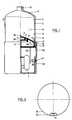
- Fig. 1shows an electrically operated automatic lubricator with a electric motor drive, which has a feed rod 2 or a spindle drives a piston 3.
- a battery 1is used to power the drive.
- the type and design of the drive itselfis comparable to that in DE-PS-43 21 452 or DE-U-92 14 096 disclosed solutions.
- the piston 3is within a Cylinder 4, the lubricant 6 or another in its interior 5 absorbs liquid or gaseous medium.
- a Outlet 8is provided for dispensing the lubricant or the liquid medium.
- the pistonhas a convex shape 9 in cross section, which is the shape of the Cylinder in the cylinder head area 7 is adjusted accordingly.
- a spindle plate 10On the back the Piston on a spindle plate 10 to which the spindle 2 for propelling the piston attacks.
- the spindle plateextends over a portion of the back of the Piston and is via one or more webs 11 with the piston crown 12 of the Piston 3 connected and also centered via a centering element 104.
- a gap 15is formed, which moves the piston 3 within of the cylinder 4 enables.
- the gapis so small that the lubricant can pass through through the gap is not possible.
- To improve the seallies on the piston rim 13 over the gap 15 as a sealing body 16 a one-piece Sealing lip 17 on the piston rim.
- the sealing lip 17rises from Piston rim to the inner wall of the cylinder, so that when there is strong pressure in the interior 5 of the cylinder 4, the sealing lip 17 on the cylinder inner wall 14 and on the Piston 3 is pressed.
- the housing 18 and the cylinder 4are detachable, e.g. through a thread, with each other connected. This allows the emptied cylinder to be separated from that Housing and at the same time the locking of a filled cylinder by one Housing 18 after the piston 3 has returned to its initial position. If the cylinder is permanently connected to the housing, it is possible to move on Removal of a reverse movement lock, which occurs when the automatic Lubricator returns the piston to its original position prevented by pouring lubricant into the cylinder through the outlet opening 8 to refill the automatic lubricator and ready for use.
- an empty cylindercan be used can be easily replaced with a newly filled cylinder and the empty one The cylinder can then be recycled.
- the different Principles and possibilities of the recyclability of individual components of the automatic lubricatorwill be described later.
- the lubricant dispenser in the housing 18has a circuit board 20 on which a for example as an ASIC microprocessor 54 and memory and further control devices are arranged to drive the piston accordingly to control.
- a for example as an ASIC microprocessor 54 and memory and further control devicesare arranged to drive the piston accordingly to control.
- the electronicsare preset by storing the corresponding values that the automatic lubricator per unit time, e.g. a day, one certain amount of lubricant, e.g. 2 or 4 g.
- This preset Deliveryis triggered by the switch and can then only by switching off the supply voltage one arranged in the device Battery. Usually, however, a shutdown is not necessary and the lubricator works until it is completely empty.
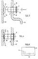
- FIG. 2shows a top view of the rear part of the lubricator. It can be seen that the switch 21, which is explained in more detail below is in a recess 22 of the circular cylindrical housing 18 and thus does not project beyond the outer circumference 24 of the housing 18. The switch is now on 21 protected within the housing shape and offers no contact surface for the Lubricant protruding objects.
- Fig. 3is an enlarged section of the switch 21 and its interaction shown with a contact means 25 in the non-activated state.
- the The switchconsists of a cylindrical pin 26 which is in an opening 27 of the Housing 18 is inserted.
- the pinhas a pin head 28, the diameter of which is larger than the diameter of the opening 27.
- Below the pin headis a Sealing ring 29 arranged.
- the cylindrical part of the pin 26has two projections 30 and 31 which are beveled in one direction, the distance between them corresponds to each other the wall thickness of the housing 18. Through the circumferential Projections 30 and 31, the diameter of which is larger than that of the opening 27 a pre-fixation of the pin 26 in the housing wall is achieved.
- the pin 26can be inserted into the housing 18 from the outside are, however, as soon as the second projection 31 is inserted through the opening 27 has been, the switch 21 can only be applied with great force pull out of opening 27.
- a snap contact disc 23assigned, which in the non-active state via a convex or dome-like Has curvature 32 of a metallic plate, below the two contacts 34 are located, the conductive connection of which triggers a switch-on of the device.
- FIG. 4shows the activation of the lubricant dispenser after the pin 26 has been pressed in shown in the housing 18.
- the curved part 32 of the snap contact disk 25is pressed down so far that the snap contact disk touches the contacts 34 lying beneath it at the same time and thus establishes an electrical connection between the two contacts 34. If the pin 26 is then removed, it remains in contact and thus when switching on the lubricator or in an alternative embodiment is the snap contact disc again in that shown in Fig. 3 Starting position can be moved back and thus decouples the electrical parts for the drive of the automatic lubricator from the energy supply.
- the second projection 30 of the pin 26 within the Housing 18is located and prevents pulling out of the switch 21. At the same time it also seals the interior of the lubricator outside and inside against the outside of the lubricator. For another seal provides the seal 29, which between the pin head 28 and the outer wall of the housing 18 is pressed.
- splash protectionas well as explosion protection is achieved because the inside the housing is sealed against external influences as well Exterior of the housing against occurring faults e.g. Sparking or electrical flashovers is shielded. Such protection is special then necessary if such a lubricator is used in the mine where the triggering of explosions must be prevented.
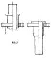
- Fig. 5shows on the left a - single or multi-stage - telescopic spindle with driven Gear in the extended state, while on the right the telescopic spindle up is extended to the maximum stop.
- the use of a telescopic spindle for Propulsion of the pistonsaves a lot of space and places above it is also a very precise means of propelling the piston, because dealing with a Let the telescopic spindle adjust even the smallest length changes.
- a pressure sensorcoupled to the microprocessor 36 to provide the the when a certain pressure in the cylinder is exceeded The device switches off until the pressure is below a specified value has dropped.
- a pressure sensor 36can, as shown, within the Cylinder 4 can also be used in the rear area of the housing 18, when the pressure sensor can measure the force acting on the piston.
- the pressure sensor 36is arranged on the vertex of the piston 3, so that it protrude into the outlet area 8 of the cylinder when the piston is advanced can also remove the last residues of the lubricant from the outlet area to press.
- the entire cylinder or only a part of itis for reading the piston jacking transparent, i.e. transparent, trained. This is particularly easy then achieve if the cylinder is made of plastic or glass.
- the Cylinder in the transparent area along its main axisa scaling in shape from alphanumeric characters or abstract characters like simple dashes having. It may be very advantageous that the distance a certain amount of lubricant delivery between the scaling characters corresponds and a corresponding assignment of the amount of lubricant dispensed on the distance between the scaling characters on the housing is documented. Thus, the viewer can quickly see the amount of lubricant dispensed determine or a statement about the amount of lubricant still available to meet. The smaller the distance between the scaling characters, the more accurate the estimate.
- the submission notificationis particularly accurate when A scaling symbol is assigned to the set delivery quantity per unit of time is.
- the piston rim 13 or the sealing lip 17is provided in a striking color design, so that there is a very clearly visible difference between the piston rim 13 and the sets transparent material. It can be used to record the reading more quickly under certain circumstances it may also be advisable to use a consecutive number to make counting easier.
- a replaceable batterycan be used to supply the lubricant with energy or an accumulator can be used, but also a network-dependent one Power supply.
- a stepper motor 55as the drive, of the depending on supplied electrical pulses or signals Spindle 2 or the piston 3 drives.
- the circuit board 20a pulse / control signal generator 53 is provided, which within a certain Unit of time generates a certain number of electrical pulses / control signals and feeds these signals to a control evaluation unit 54 of the stepping motor 55. 7-.
- a control or a driveis thereby achieved which is independent of external influences and above all the disadvantages of a temperature dependency, which is given regularly in DC drives, is avoided in principle.
- a counter evaluation unit in the control evaluation unit 54is provided, which is delivered to the stepper motor Control pulses counts, buffered in a volatile memory RAM, and with a predetermined value "maximum pulse number", which in a non-volatile Memory ROM is stored, compares.
- the "maximum number of pulses"corresponds the maximum propulsion of the piston 3 in the cylinder when the piston hits the inner wall of the cylinder touched in the cylinder head area 7.
- the evaluation unitcompares the number of control pulses delivered with the value "maximum pulse number” and the control unit 54 switches when the number of control pulses counted corresponds to the number of the stored "maximum pulse number", the stepper motor. If the number of control pulses counted is below the "maximum pulse number" lies, the propulsion of the spindle or the piston around the given Control pulse corresponding step size released.
- the lubricator with a corresponding display unit 50 in the form a display as shown in Fig. 6, provided or connectedthe Number of counts emitted and thus a measure of those emitted Lubricant quantity or a measure of the remaining lubricant quantity is displayed there in absolute numbers (e.g. 1225) or as a percentage (e.g. 12.5%) and / or in relation to the total number (1225/5000), so that the user of the The lubricator is always very precise about the piston deflection and the Lubricant quantity delivered or still remaining in the lubricator can inform.
- the displaycan also be done in such a way that the display 50 two has different types of alphanumeric or abstract characters, namely a first group of characters consisting of a number of first characters 51 exists, the number of the first characters of the output to the stepper motor Number of control pulses is proportional and and from a second group of characters consists of a second number 52 of characters, the Number of the first 51 and second 52 characters of the number of the total possible control pulses is proportional and therefore a measure of the total amount of lubricant.
- Such an incremental display especially with a stepper motor as incremental Driveis very simple and accurate in terms of absolute display and absolute finest changes in the amount of lubricant dispensed or the amount of residual lubricant.
- acan be used instead of a pressure sensor
- Current consumption monitoring devicecan be provided, which, as soon as a previously programmed maximum motor current consumption exceeded is switched off, the electronics and thus the lubricator.
- the displayallows a very precise indication of the amount of lubricant dispensed in absolute numbers, d. H. in ml per unit of time, which also gives the machine maintenance staff more information about the Condition and wear of the machine to be lubricated is maintained. This eases under Under certain circumstances, the decision-making about the continued operation of the lubrication Machine unit or the replacement of certain units, in short face failure.
- Both machine-dependent control of the automatic lubricatoris provided that the lubricator contactlessly by means of a magnetic switch is activated or deactivated.
- a magnetic switchon the board 20 attached so that it is as close as possible to the wall of the housing cover located.
- a coilis attached to the housing cover, which at Current flow switches the magnetic switch inside the case and the drive activated or deactivated. If there is no voltage on the coil, it will Drive system deactivated. If the coil is under tension, it will Drive system activated.
- the voltage signals supplied to the coilare from the machine unit to be lubricated and the non-contact control of the drive allows mechanical decoupling between live Lines outside the housing from the inside of the housing and avoids thus possible flashover voltages. This is an effective one Explosion and water protection of the automatic lubricator guaranteed.
- the coilpreferably cast in plastic with an iron core, is designed that with a simple handle in a designated recess of the Housing can be pressed in and thus comparable to the pin 21 within the contour of the housing lies.
- the automatic lubricatoris completely empty, there are two basic alternatives for the continued use of the automatic lubricator. On the other hand, it is therefore advantageous to only replace the components which are subject to heavy loads and can be replaced inexpensively can. This is e.g. the cylinder, the housing 18 and the piston 5, which at detachable connection with the drive and the electronic control parts, e.g. the circuit board 20, separated from it after the lubricant has been emptied, and one targeted plastic recycling.
- the cylinder, the housing 18 and the piston 5which at detachable connection with the drive and the electronic control parts, e.g. the circuit board 20, separated from it after the lubricant has been emptied, and one targeted plastic recycling.
- a switchable backstopis provided for the piston, which, when refilling the cylinder, causes the piston to move into its original starting position allowed. Then the cylinder can be filled by filling lubricant into the cylinder through the outlet opening 8 take place, with the filling of the cylinder at the same time the piston in his Starting position is pushed back.
- FIG. 8ashows the bottom view of a piston 3 with corresponding strut and stiffeners 57 to prevent the piston from deforming upon start-up counteract.
- the pressure inside the lubricantcan be at 4 bar and more, such stiffening elements 57 expedient.
- the pistonis equipped with an O-ring 58 to ensure a good one Sealing between the cylinder interior and the cylinder wall guarantee.
- FIG. 8bshows a side view of the piston 3 with a groove 59 for the O-ring 58.
- FIG. 8cshows an enlarged cross-sectional view from the piston according to FIG. 8b, with the previously described stiffening elements 57, the groove 59 for the O-ring 58 and sealing body 16 located on the piston side as part of the piston.
- the sealing bodiesseal the cylinder space from the housing.
- Fig. 8dshows once again an overall cross section through the piston with the Stiffening element 57 for centering the plate 10.
- the motor for propelling the pistonis preferably a DC motor 90, which is controlled by electronics.
- the rotation the motor shaft (not shown)is via the gear 91, which is preferably is designed as a gear transmission, geared down, for. B. in a ratio of 1: 6221.
- the Lubricant dispenseris supplied with energy by means of the battery 1, the batteries preferably consisting of three alkaline mignon cells. 11a- exist, which are packed side by side in a hosiery tube, are connected in series and are completely wired with a plug contact. The During assembly, the plug only has to be attached to the electronics Plug socket are plugged (not shown).
- Threaded bushin the last gear of the gearbox.
- Threaded bushingis a thread or Feed rod 2.
- the pitch of the threadis very small and is preferably 0.5 mm. So if the engine turns 6221 times, so the last gear has made a full turn and the feed or Threaded rod 2 and thus also the piston 3 a travel of 0.5 mm traveled. Furthermore, on the first driven gear of the gear 91 bad reflecting area attached.
- buttons on the electronicsThere are buttons on the electronics, two sockets - 2-pin for battery, 6 pin for motor and sensor -, a microprocessor, a time quartz and various Resistances. These parts are equipped with SMD.
- the bad already mentioned reflective areae.g. B. a black, matte plastic sticker, which is considerable reflected less well than the brass of the gear.
- an optical infrared sensoris installed into the gear. This sensor consists of a transmitter and a receiver. The electronics are now accurate specified how often a signal from sensor must come to the entire To have completed the travel. Then the system switches on time after the preset runtime.
- Testshave determined how long it takes at 4 bar cylinder pressure, to get X signals from the sensor. This describes the "worst case”. are The system switches in this predetermined time if the X signals were not recognized since either there is a technical defect (engine, battery, transmission or sensor), or the pressure has exceeded 4 bar (engine speed decreases).
- Two resistorsare attached to the electronics to preset the run times. Because there are four positions where these resistors are attached there are four different options, the four different terms mean, e.g. B. 1, 3, 6, or 12 months.
- the control deviceis predefined that in 12-month operation approximately every 6th Hours to be lubricated in order to achieve a one-shift operation To ensure lubrication point supply. So with a 12-month donor a pressure builds up in the cylinder every 6 hours. Because the duration of the pressure build-up is always the same, the different terms differ only in that the break between donations is different. A 6 month donor runs every 3 hours, a 3-month donor every 90 minutes, a 1-month donor every 30 minutes. This is advantageous because it is important for a short term the impulses to come as shortly as possible in order to create a permanent Coming up to pressure as close as possible. With long terms, this is of secondary importance Importance.
- the activation pinis pre-pressed into the cover as previously described. The user presses this activation pin all the way into the housing of the lubricant dispenser the system is activated.
- the identification to the user which default setting for the using the lubricatoris programmed by marking the Activation pin, e.g. B. by a color marking.
- the sensorAfter activation, the sensor is automatically adjusted first. There the electronics specify the time in which X signals come from the sensor the intensity of the sensor is changed until the receiver received this signal optimally. This is done by making 1 6 different Settings of the sensor current gives what is a change in brightness of the Transmitter means. If the intensity of the transmitter is too high, it may be that the black sticker reflecting the infrared ray. If the intensity is too low, it could it also doesn't reflect the brass of the gear. This automatic adjustment of the sensor takes about 4 seconds. Should not be the default during this time Number of signals are detected, the system runs again for 4 seconds without to adjust again. If the system switches off after 4 seconds, the sensor works optimally, the system is OK. But the system is running There is no defect at all or for 8 seconds.
- the amount of lubricantis dispensed according to the teaching of DE-U-9214096 a predetermined setting affects the duration of the lubricant delivery.
- a predetermined settingaffects the duration of the lubricant delivery.
- an open-loop controlIn the described according to the invention Lubricator, on the other hand, the amount of lubricant is direct, and not monitored over a period of time. This is the volume of lubricant dispensed measured via the electronics described above and the lubricant supply after delivery of a predetermined volume - this corresponds to the corresponding one Feed path stopped. The volume of lubricant dispensed is therefore about the number of engine revolutions or signal pulses measured. It is a closed control loop that is differs significantly from the open-loop control DE-U-9214096.
- FIG. 9shows a further basic illustration of the lubricant dispensing device according to the invention with batteries 1 for power supply, a feed rod 2, which is driven by a motor 90 and in which a gear 91, preferably a reduction gear between the feed rod 2 and the Motor 90 is arranged.
- the feed rodis connected to the piston 3, which within a cylinder 4 with a transparent cylinder wall arranged previously described integrated scale.
- the operational state after the lubricator is manufacturedis the Dispensing opening 8 with one with the cylinder wall or the dispensing opening 8 provided integrally connected cap 92. Before using the Lubricator, the cap 92 must be separated, for. B. by To cut.
- the delivery area of the cylinderis on the outside with a External thread 93 provided in a lubrication point with corresponding internal thread to be screwed in.
- the closure cap 92preferably projects beyond the external thread in its outer circumference 93, so that screwing the external thread into a lubrication point only after removing the cap is possible.
- Such an embodimentis shown in Figs. 10, 12a and 12b.
- 10is also a Thread 100 shown, which for screwing with a corresponding Counter thread of the housing - see Fig. 11a- serves.
- the cylinder after screwing to the housingcan no longer be detached from it.
- One of the cylinder wall-repellent border 101serves for better sealing and Fixing the screw cap.
- FIG. 11ashows, in a further embodiment, the housing part 18 of the lubricant dispensing device, in the batteries 1, the control electronics board 20 and the other drive parts are housed.
- the control board 20is located in a guide 95 for mechanical stabilization of the board.
- the leadership 95consists preferably of a groove 96 formed in the housing 18
- An internal thread 110connects to the cylinder with the lubricant see which one with the external thread 100 - see Fig. 10- of the cylinder 4 is connectable.
- FIG. 11bshows, in a further embodiment, the housing part 18 of the lubricant dispensing device, in the batteries 1, the control electronics board 20 and the other drive parts are housed.
- the control board 20is located in a guide 95 for mechanical stabilization of the board.
- the leadership 95consists preferably of a groove 96 formed in the housing 18
- An internal thread 110connects to the cylinder with the lubricant see which one with the external thread 100 - see Fig. 10- of the cylinder 4
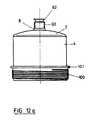
- FIG. 12ashows the cylinder of the lubricant dispenser in a further plan view with scaling marks applied so that the user can fill the level the lubricant dispenser can be seen.
- Fig. 12bshows again that the cap 92 is a larger one Has outer diameter than the external thread 93, so that screwing of the external thread into a lubrication point only after the Cap 92 is possible, which with the dispensing area of the lubricator is integrally connected.
- FIG. 13shows a stabilizer element 102 with an opening 103, which has a Internal thread 104 for receiving the lubricator with its external thread 93 is provided.
- the stabilizer elementcan be on an external thread Lubrication point are screwed on and on the other side the lubricant dispenser take up.
- Lubrication pointare screwed on and on the other side the lubricant dispenser take up.
- the stabilizer elementconsists of an elastic medium
- the can also Lubricant dispensercan be screwed directly to the lubrication point and the stabilizer element is then compressed and thus ensures a stable Location of the lubricant dispenser to the lubrication point.
Landscapes
- General Engineering & Computer Science (AREA)
- Engineering & Computer Science (AREA)
- Mechanical Engineering (AREA)
- Coating Apparatus (AREA)
- Lubrication Of Internal Combustion Engines (AREA)
- Actuator (AREA)
- General Details Of Gearings (AREA)
- Reciprocating Pumps (AREA)
- Auxiliary Devices For Machine Tools (AREA)
- Presses And Accessory Devices Thereof (AREA)
- Hydraulic Motors (AREA)
- Spray Control Apparatus (AREA)
- Feeding, Discharge, Calcimining, Fusing, And Gas-Generation Devices (AREA)
- Lubricants (AREA)
Abstract
Description
Translated fromGermanDie Erfindung betrifft eine Einrichtung zur automatischen Schmierstoffabgabe miteinem in einem Zylinder angeordneten Kolben und einem damit verbundenenAntriebsmittel. Eine solche Einrichtung ist aus der DE-PS-43 21 452 bzw. DE-U-9214 096 bekannt. Während in DE-PS-43 21 452 eine Lösung vorgeschlagen wird,bei der Schmiermittel mittels eines Druckkolbens aus dem Zylinder direkt gedrücktwird, sich also das Schmiermittel unmittelbar selbst im Zylinder befindet, wird beider Lösung nach DE-U-92 14 096 vorgeschlagen, eine Schmiermittelpackung in denZylinder einzusetzen und mittels eines Kolbens auszupressen.The invention relates to a device for automatic lubricant dispensinga piston arranged in a cylinder and an associated pistonDrive means. Such a device is from DE-PS-43 21 452 and DE-U-9214 096 known. While a solution is proposed in DE-PS-43 21 452,when the lubricant is pressed directly out of the cylinder by means of a pressure pistonis, i.e. the lubricant is located directly in the cylinder, is atthe solution according to DE-U-92 14 096 proposed a lubricant pack in theInsert cylinder and press out using a piston.
Den beiden bekannten Lösungen haften mehrere Nachteile an. So besteht derNachteil der Lösung nach DE-PS-43 21 452 besonders darin, daß beim Herausdrückendes Schmierstoffes aus dem Zylinder der Kolben aufgrund seinergeometrischen Form sehr unterschiedlich beansprucht wird und dazu neigt, amäußeren Rand, der der Zylinderinnenwandung gegenüberliegt, leicht wegzukippenbzw. einen Spalt zwischen dem Kolben und der Zylinderinnenwandung entstehenzu lassen, durch den Schmierstoff in den Bereich des Antriebs gelangen kann. Injedem Fall sind die in dieser Druckschrift vorgeschlagenen Maßnahmen zurAbdichtung des Spaltes zwischen dem Kolben und der Zylinderinnenwandung völlig unzureichend. Darüber hinaus wird der Schmierstoffgeber erst durch Einstellen derSpendezeit mit einer Staffelung im gewünschten Zeitabstand durch elektronischeSteuerung aktiviert, was insbesondere dann nachteilig ist, wenn der Schmierstoffgeberan Stellen untergebracht ist, die nur schwer zugänglich sind und einEinstellen der Spendezeit kaum erlauben. Darüber hinaus ist die Ausbildung derMittel zur Einstellung der Spendezeit bei dem Gerät aufgrund ihrer häufigeneinmaligen Nutzung wenig wirtschaftlich.The two known solutions have several disadvantages. So there isDisadvantage of the solution according to DE-PS-43 21 452 especially in that when pressing outof the lubricant from the cylinder of the piston due to itgeometric shape is used very differently and tends tothe outer edge, which lies opposite the inner wall of the cylinder, can be easily tilted awayor a gap between the piston and the cylinder inner wallthrough which lubricant can get into the area of the drive. InIn any case, the measures proposed in this publication are:Sealing the gap between the piston and the cylinder inner wall completelyinsufficient. In addition, the lubricator is only activated by adjusting theDonation time with a staggering at the desired interval by electronicControl activated, which is particularly disadvantageous when the lubricatoris housed in places that are difficult to access and aHardly allow setting the donation time. In addition, the training ofMeans to adjust the dispensing time for the device due to its frequentsingle use little economical.
Bei dem aus DE-U-92 14 096.3 bekannten Schmierstoffgeber gibt es aufgrund derUnterbringung des Schmierstoffes in einer Schmiermittelpackung zwar keinDichtigkeitsproblem, jedoch kann die Schmiermittelpackung nicht vollständigentleert werden, da der Kolben im Querschnitt stufig ausgebildet ist und dieSchmiermittelpackung prinzipiell nicht vollständig entleert werden kann. Somitbleiben stets Rückstände in der Schmiermittelpackung zurück, so daß nur einesuboptimale Nutzung des gesamten Schmierstoffs in der Schmiermittelpackungerfolgt. Ferner ist es bei dem bekannten Schmierstoffgeber möglich, daß diese unterungünstigen Umweltbedingungen Explosionen verursachen.In the lubricator known from DE-U-92 14 096.3 there are due to thePlacing the lubricant in a lubricant pack does notTightness problem, however the lubricant pack cannot be completebe emptied, since the piston has a stepped cross section and theIn principle, the lubricant pack cannot be completely emptied. Consequentlyresidues always remain in the lubricant pack, so that only onesuboptimal use of all lubricant in the lubricant packhe follows. Furthermore, it is possible with the known lubricator that this underunfavorable environmental conditions cause explosions.
Es ist daher Aufgabe der vorliegenden Erfindung, bei einer Einrichtung zurautomatischen Schmierstoffabgabe mit einem in einem Zylinder angeordnetenKolben und einem damit verbundenen Antrieb die dem Stand der Technikanhaftenden Nachteile zu vermeiden.It is therefore an object of the present invention in a device forautomatic lubricant dispensing with one arranged in a cylinderPistons and an associated drive the state of the artto avoid inherent disadvantages.
Erfindungsgemäß wird dies mit einer Einrichtung zur automatischen Schmierstoffabgabenach Anspruch 1 erreicht. Vorteilhafte Weiterbildungen der Erfindungen sindin den Unteransprüchen beschrieben.According to the invention, this is done with a device for automatic lubricant dispensingreached according to
Es ist sehr vorteilhaft, wenn die erfindungsgemäße Einrichtung einen spritzwassergeschütztenEinschalter aufweist, der die internationale Norm ID 65 erfüllt. DerSpritzwasserschutz wird durch eine entsprechende Abdichtung des Einschalterserreicht, wodurch gleichzeitig auch die gesamte Einrichtung zur automatischenSchmierstoffgabe explosionsgeschützt ist. Nach der Aktivierung des Einschaltersist eine Ausschaltung der Einrichtung nur noch durch Abschaltung der Energieversorgungmöglich. Der bevorzugte Verzicht auf eine Ausschaltfunktion ist unproblematisch,weil der automatische Schmierstoffgeber praktisch nie ausgeschaltetwerden muß, sondern aufgrund einer voreingestellten Schmierstoffabgabemengepro Tag oder sonstiger Zeiteinheit solange in Betrieb bleibt, bis sämtlicherSchmierstoff aus dem Zylinder ausgegeben worden ist.It is very advantageous if the device according to the invention is splash-proofHas a switch that meets the international standard ID 65. TheSplash protection is provided by an appropriate seal on the switchachieved, which also the entire facility for automaticLubricant is explosion-proof. After activating the switchis a switch off of the facility only by switching off the energy supplypossible. The preferred avoidance of a switch-off function is unproblematic,because the automatic lubricator is almost never switched offmust be, but due to a preset amount of lubricantper day or other unit of time remains in operation until allLubricant has been expelled from the cylinder.
Der Einschalter ist vorzugsweise als zylindrischer Stift ausgeführt, der mit einem alsSprungkontaktscheibe ausgebildeten Kontaktmittel zusammenwirkt. Die Sprungkontaktscheibeist auf einer Platine zusammen mit den anderen elektrischen Bauteilenzur Steuerung der Schmierstoffabgabe angeordnet. Die Sprungkontaktscheibe weisteine kalottenähnliche konvexe Querschnittsform auf, solange die Einrichtung nochnicht aktiviert ist. Der Sprungkontaktscheibe liegt der Einschalter gegenüber, der ineiner Öffnung der Gehäusewandung der Einrichtung angeordnet ist. Wird der alsAktivierungsstift ausgebildete Einschalter in das Gehäuse eingedrückt, so drückt dervordere Teil des Aktivierungsstiftes bzw. des Einschalters die konvexe Form derSprungkontaktscheibe in eine konkave Form und die so gebogene Kontaktscheibe,welche elektrisch leitend ausgeführt ist, berührt gleichzeitig zwei unterhalb derKontaktscheibe angeordnete Kontakte, durch die die Einrichtung bei Kontaktierunggestartet wird.The switch is preferably designed as a cylindrical pin with aSnap contact disk trained contact means interacts. The snap contact discis on a circuit board together with the other electrical componentsarranged to control the lubricant delivery. The snap contact disc pointsa dome-like convex cross-sectional shape while the facility is still openis not activated. The snap contact disc is opposite the on switch, which inan opening of the housing wall of the device is arranged. If the asActivation pin trained switch pressed into the housing, so pressesfront part of the activation pin or the switch the convex shape of theSnap contact disc in a concave shape and the contact disc bent in this way,which is made electrically conductive, simultaneously touches two below theContact disc arranged contacts through which the device when contactingis started.
Vorzugsweise weist der Aktivierungsstift zwei umlaufende Vorsprünge auf, die ineinem Abstand entsprechend der Wandstärke des Gehäuses zueinanderliegen. BeiNichtaktivierung liegt einer der Vorsprünge außenseitig und der andere Vorsprunginnenseitig des Gehäuses. Bei der Aktivierung wird der außenseitig liegendeVorsprung durch die Öffnung des Gehäuses gedrückt bis der vormals außenseitigeliegende Vorsprung innenseitig liegt und eine Zurückbewegung des Aktivierungsstiftsaus dem Gehäuse heraus verhindert. Dichtungsmittel, die unterhalb desKopfes des Aktivierungsstifts angeordnet sind, liegen nach dem Hineindrücken desAktivierungstifts außenseitig am Gehäuse an und dichten das innere des Gehäusesgegen den Außenbereich des Gehäuses ab. Eine weitere Abdichtung des Gehäuseswird durch den Vorsprung erreicht, der innenseitig an der Gehäuseinnenwandungliegt.The activation pin preferably has two circumferential projections which are ina distance corresponding to the wall thickness of the housing to each other. AtOne of the protrusions lies on the outside and the other protrusion is not activatedinside the housing. When activated, the outside isProjection pressed through the opening of the housing until the former outsidelying projection is on the inside and a return movement of the activation pinprevented from the housing. Sealant below theHead of the activation pin are arranged after pushing theActivation pin on the outside of the housing and seal the inside of the housingtowards the outside of the housing. Another seal of the housingis achieved by the projection on the inside of the housing inner walllies.
Vorzugsweise ist der Einschalter in einer Vertiefung des Gehäuses der Einrichtungangeordnet und überragt somit bei Aktivierung nicht den Außenumfang desSchmierstoffgebers.The switch is preferably in a recess in the housing of the devicearranged and thus does not project beyond the outer circumference of theLubricator.
Der Erfindung liegt ferner die Erkenntnis zugrunde, daß ein Kolben mit einer imQuerschnitt konvexen Form sehr leicht herzustellen ist und auch im Randbereichnicht dazu neigt, den Spalt zwischen dem Kolben und dem Zylinder freizugeben.Vor allem aber kann durch die Linienführung des im Querschnitt konvexen Kolbensein Dichtungskörper vorzugsweise in einer einstückigen Dichtlippe aufgenommenwerden, die bei hohem Druck im Zylinder automatisch gegen die Zylinderinnenwandung und den Kolbenrand gedrückt wird und somit für eine sehr gute Abdichtungsorgt.The invention is also based on the finding that a piston with aCross-section convex shape is very easy to manufacture and also in the edge areadoes not tend to release the gap between the piston and the cylinder.Above all, however, the lines of the piston, which is convex in cross section, can be useda sealing body is preferably received in a one-piece sealing lipat high pressure in the cylinder automatically against the inner wall of the cylinderand the piston rim is pressed and thus for a very good sealworries.
Durch die Anpassung des Zylinderkopfes an die konvexe Form des Kolbens wirddarüber hinaus eine vollständige Entleerung des Schmiermittels aus der Einrichtunggewährleistet.By adapting the cylinder head to the convex shape of the pistonalso complete drainage of the lubricant from the facilityguaranteed.
Ferner ist es zweckmäßig, wenn die Einrichtung einen Mikroprozessor und einendamit verbundenen Speicher aufweist und die Einrichtung mittels dieser Mittel aufeine bestimmte Mengenabgabe pro Zeit voreinstellbar ist, welche durch denEinschalter lediglich noch ausgelöst werden kann.It is also expedient if the device has a microprocessor and aassociated memory and the device by means of thisa certain quantity delivery per time can be preset, which is determined by theThe switch can only be triggered.
Zur Beobachtung der Entleerung der erfindungsgemäßen Einrichtung ist dieZylinderwand wenigstens teilweise aus einem transparenten Material, so daß dieSilhouette des Kolbens oder des Dichtungskörpers von außen her zu sehen ist.Längs der Zylinderhauptachse ist darüber hinaus eine Skalierung in Form vonalphanumerischen oder abstrakten Zeichen vorgesehen, so daß eine genaueAbschätzung über die Entleerung des Schmierstoffes im Zylinder angegeben werdenkann. Eine solche Anzeigevorrichtung ist sehr einfach in der Herstellung und in derAblesung und darüber hinaus sehr genau. Gerade wenn die Zylinderwandung ausKunststoff ist, läßt sich die Transparenz bzw. Durchsichtigkeit der gesamtenZylinderwandung sehr einfach herstellen.To observe the emptying of the device according to the invention, theCylinder wall at least partially made of a transparent material, so that theSilhouette of the piston or the sealing body can be seen from the outside.There is also a scaling in the form ofalphanumeric or abstract characters are provided so that an accurateEstimation of the emptying of the lubricant in the cylinder can be givencan. Such a display device is very simple to manufacture and inReading and beyond that very accurate. Especially when the cylinder wall is outIs plastic, the transparency or transparency of the entireProduce cylinder wall very easily.
Zur verbesserten Ablesung ist es sinnvoll, wenn der obere Kolbenrand oder derDichtungskörper mit einer gut sichtbaren Farbe, z.B. Signalfarbe, versehen ist.For better reading, it makes sense if the top of the piston or theSealing body with a clearly visible color, e.g. Signal color, is provided.
Es kann zweckmäßig sein, die Einrichtung von Winter- auf Sommerbetriebumzuschalten und entsprechende Mengen/Zeit-Voreinstellungen in einem nichtflüchtigen Speicher zu speichern. Durch einen weiteren Schalter kann dieUmschaltung ausgelöst werden. Damit wird die optimale Schmierstoffversorgungdurch Anpassung an die üblichen Außentemperaturen zur Winter- bzw. Sommerzeiterreicht.It may be useful to set up from winter to summernot toggle and corresponding quantity / time presets in oneto store volatile memory. Another switch can be usedSwitching can be triggered. This is the optimal supply of lubricantby adapting to the usual outside temperatures in winter or summer timereached.
Als Antriebsmittel für den automatischen Schmierstoffgeber kann ein elektrischerGleichstrom- oder Wechselstrommotor dienen, wie er als solcher im Elektromaschinenbauhäufig zur Anwendung kommt.An electrical one can be used as the drive means for the automatic lubricatorDirect current or alternating current motors are used as they are in electrical engineeringis often used.
Besonders vorteilhaft ist jedoch die Verwendung eines Schrittmotors, welcher denKolben innerhalb des Zylinders des Schmierstoffgebers antreibt. Der Vorteil liegtbesonders darin, daß ein Schrittmotor sich für den erfindungsgemäßen Zweckbesser ansteuern läßt, weil er in Abhängigkeit von elektrischen Signalen, z. B. voneiner Anzahl von elektrischen Impulsen, gradgenau und somit gegenüber Temperatureinflüssenunabhängiger reagiert, als dies bei z. B. Gleichstrommotoren der Fallist. Die Verwendung eines Schrittmotors erlaubt damit eine insgesamt einfachereAnsteuerung des Antriebs von einer Steuerplatine, die vor allem eine Impulszähleinrichtungund eine Einrichtung aufweist, die in Abhängigkeit der vorliegendenelektrischen Impulse die Schrittweite des Motors steuert. Auf diese Art und Weiseläßt sich auch das Abschalten des Schrittmotors bewirken, wenn dieser den Kolbenbis in den Ausgabebereich des Zylinders gedrückt hat. Dies erfolgt dadurch, daß ineinem Speicher eine Anzahl von Schrittmotor-Steuer-Impulsen vorgegeben wird,und sobald diese Anzahl erreicht wird, der Schrittmotor bzw. der Schmierstoffgeberabgeschaltet wird. Somit besteht die Abschaltungseinrichtung des Schrittmotorsaus einem Vergleicher bzw. einer Steuereinheit mit einem Vergleichsprogramm,welches die Anzahl der bereits eingestellten Impulse mit der gespeicherten Maximal-Impulszahlvergleicht und in Abhängigkeit davon ein Steuersignal an den Schrittmotorweiterleitet und eine Weiterbewegung des Schrittmotors um eine bestimmteSchrittanzahl freigibt oder diesen abschaltet.However, it is particularly advantageous to use a stepper motor whichDrives the piston inside the cylinder of the lubricator. The advantage liesespecially in the fact that a stepper motor is suitable for the purpose according to the inventioncan be controlled better because it is dependent on electrical signals, e.g. B. froma number of electrical impulses, accurate to the degree and thus against temperature influencesresponds more independently than with z. B. DC motors the caseis. The use of a stepper motor thus allows a simpler overallControl of the drive from a control board, which is primarily a pulse counterand has a device which, depending on the presentelectrical impulses control the step size of the motor. That waycan also cause the stepping motor to be switched off when the pistonup to the cylinder's output area. This is done in thata number of stepper motor control pulses is given to a memory,and as soon as this number is reached, the stepper motor or the lubricatoris switched off. There is therefore a switch-off device for the stepper motorfrom a comparator or a control unit with a comparison program,which is the number of pulses already set with the stored maximum number of pulsescompares and depending on this a control signal to the stepper motorpasses on and a further movement of the stepper motor by a certainReleases the number of steps or switches it off.
Als Impulserzeugungseinrichtung kann ein Impuls-/Steuersignalgenerator dienen,welcher zeitabhängig, z. B. 10 Impulse pro Tag oder abhängig vom Bedarf der zuschmierenden Maschineneinheit Impulse erzeugt, so daß bei maschinenunabhängigenBetrieb der Schrittmotor und damit der Kolben innerhalb einer bestimmtenZeiteinheit eine bestimmte Schrittauslenkung erfährt und bei maschinengebundenerAnsteuerung der Impulsgenerator die nötige Anzahl von Impulsen auf Bedarferzeugt.A pulse / control signal generator can serve as the pulse generating device,which time-dependent, e.g. B. 10 impulses per day or depending on the needs oflubricating machine unit generates pulses so that machine-independentOperation of the stepper motor and thus the piston within a certainUnit of time experiences a certain step deflection and with machine-boundControl of the pulse generator the required number of pulses on demandgenerated.
Nachfolgend wird die Erfindung anhand eines Ausführungsbeispiels näher erläutert.In der Zeichnung stellen dar:
- Fig. 1
- einen Teilquerschnitt/Teilaufsicht auf eine erfindungsgemäße Einrichtungzur automatischen Schmierstoffabgabe;
- Fig. 2
- ein Querschnitt durch die Einrichtung in Fig. 1
- Fig. 3
- ein Teilausschnitt aus Fig. 1 bei Nichtaktivierung;
- Fig. 4
- ein Teilausschnitt aus Fig. 1 bei Aktivierung der Einrichtung;
- Fig. 5
- eine besondere Ausführung des Antriebs als Teleskopspindel mit getriebenemZahnrad im unausgefahrenen und ausgefahrenen Zustand;
- Fig. 6
- Darstellungsansicht einer Anzeige;
- Fig. 7
- Prinzipblockschaltbild der elektrischen Ansteuerung des Schmierstoffgebers;und
- Fig. 8a
- Unteransicht eines für den erfindungsgemäßen Schmierstoffgeberverwendeten Kolbens.
- Fig. 8b
- eine Seitenansicht des in Fig.
8a dargestellten Kolbens 3, jedoch nochohne O-Ring 58. - Fig. 8c
- Querschnittsausriß aus dem Kolben nach Fig. 8b mit den zuvor beschriebenenVersteifungselementen 57, mit einer Nut für den O-
Ring 58sowie an der Kolbenseite befindlichen Dichtungskörper 16 als Teil desKolbens 3. - Fig. 8d
- Querschnitt durch den Kolben
mit dem Versteifungselement 57 zurZentrierung derPlatte 10 - Fig. 9
- eine weitere Prinzipdarstellung des Schmierstoffgebers im Querschnitt
- Fig. 10
- Querschnitt durch den Zylinder
- Fig. 11a
- Querschnitt durch das Gehäuse
- Fig. 11b
- Querschnitt durch das Gehäuse entlang der Linie E-E in Fig. 11a
- Fig. 12a
- Aufsicht auf den Zylinder
- Fig. 12b
- Querschnittausriß gemäß 12a
- Fig. 13
- Stabilisatorelement
- Fig. 1
- a partial cross section / partial supervision of a device according to the invention for automatic lubricant delivery;
- Fig. 2
- a cross section through the device in Fig. 1st
- Fig. 3
- a partial section of Figure 1 when not activated.
- Fig. 4
- a partial section of Figure 1 when activating the device.
- Fig. 5
- a special design of the drive as a telescopic spindle with a driven gearwheel in the extended and extended state;
- Fig. 6
- Display view of an ad;
- Fig. 7
- Block diagram of the electrical control of the lubricator; and
- Fig. 8a
- Bottom view of a piston used for the lubricator according to the invention.
- Fig. 8b
- a side view of the
piston 3 shown in Fig. 8a, but still without O-ring 58th - Fig. 8c
- 8b with the previously described stiffening
elements 57, with a groove for the O-ring 58 and sealingbody 16 located on the piston side as part of thepiston 3. - Fig. 8d
- Cross section through the piston with the stiffening
element 57 for centering theplate 10 - Fig. 9
- another schematic diagram of the lubricator in cross section
- Fig. 10
- Cross section through the cylinder
- Fig. 11a
- Cross section through the housing
- Fig. 11b
- Cross section through the housing along the line EE in Fig. 11a
- Fig. 12a
- Top view of the cylinder
- Fig. 12b
- Cross-section extraction according to 12a
- Fig. 13
- Stabilizer element
Fig. 1 zeigt ein elektrisch betriebenen automatischen Schmierstoffgeber mit einemelektromotorischen Antrieb, der über eine Vorschubstange 2 oder eine Spindeleinen Kolben 3 antreibt. Zur Energieversorgung des Antriebs dient eine Batterie 1.Die Art und Ausgestaltung des Antriebs selbst ist vergleichbar der in DE-PS-43 21452 oder DE-U-92 14 096 offenbarten Lösungen. Der Kolben 3 liegt innerhalb einesZylinders 4, der in seinem Innenraum 5 ein Schmierstoff 6 oder ein anderesflüssiges oder gasförmiges Medium aufnimmt. Im Zylinderkopfbereich 7 ist einAuslaß 8 zur Abgabe des Schmierstoffes bzw. des flüssigen Mediums vorgesehen.Fig. 1 shows an electrically operated automatic lubricator with aelectric motor drive, which has a
Der Kolben weist im Querschnitt eine konvexe Form 9 auf, der die Form desZylinders im Zylinderkopfbereich 7 entsprechend angepaßt ist. Rückseitig weist derKolben eine Spindelplatte 10 auf, an die die Spindel 2 zum Vortrieb des Kolbensangreift. Die Spindelplatte erstreckt sich über einen Teilbereich der Rückseite desKolbens und ist über einen oder mehrere Stege 11 mit dem Kolbenboden 12 desKolbens 3 verbunden und ferner über ein Zentrierelement 104 zentriert.The piston has a
Zwischen dem Rand 13 des Kolbens 3 und der Zylinderinnenwandung 14 desZylinders 4, ist ein Spalt 15 ausgebildet, der ein Verfahren des Kolbens 3 innerhalbdes Zylinders 4 ermöglicht. Der Spalt ist so klein, daß ein Durchtritt des Schmierstoffesdurch den Spalt nicht möglich ist. Zur Verbesserung der Abdichtung liegtauf dem Kolbenrand 13 über dem Spalt 15 als Dichtungskörper 16 eine einstückigeDichtlippe 17 auf dem Kolbenrand auf. Die Dichtungslippe 17 erhebt sich vomKolbenrand zur Zylinderinnenwandung, so daß bei starkem Druck im Innenraum 5des Zylinders 4 die Dichtungslippe 17 an die Zylinderinnenwandung 14 und auf demKolben 3 gedrückt wird.Between the
Während der Kolben im Zylinder angeordnet ist, sind die Mittel zum Antrieb desKolbens 3 im an dem Zylinder 4 anschließenden Gehäuse 18 angeordnet, welchesden Zylinder im Überlappungsbereich 19 umfaßt.While the piston is arranged in the cylinder, the means for driving the
Das Gehäuse 18 und der Zylinder 4 sind lösbar, z.B. durch ein Gewinde, miteinanderverbunden. Dies erlaubt eine Trennung des geleerten Zylinders von demGehäuse und gleichzeitig die Arretierung eines gefüllten Zylinders von einemGehäuse 18, nachdem der Kolben 3 in seine Ausgangsstellung zurückgefahren ist.Wird der Zylinder mit dem Gehäuse unlösbar verbunden, so ist es möglich, nachAufhebung einer Rückbewegungssperre, welche bei Betrieb des automatischenSchmierstoffgebers die Rückbewegung des Kolbens in seine Ausgangsstellung verhindert, durch Einfüllen von Schmierstoff in den Zylinder über die Ausgangsöffnung8, um den automatischen Schmierstoffgeber wieder zu befüllen undbetriebsbereit zu machen.The
Ferner ist es sinnvoll, das Innenleben des Gehäuses, also Antrieb und elektrischeTeile, mit diesem lösbar zu verbinden, so daß nach dem Verbrauch des SchmierstoffsZylinder und Gehäuse, vorzugsweise auch der Kolben 3, vom Antrieb unddessen elektronischen Ansteuerungsteilen getrennt und einer gezielten Entsorgungzugeführt werden können, die vor allem dann einfach ist, wenn Gehäuse 18,Zylinder 4 als auch Kolben 3 aus Kunststoff bestehen und somit nach demVerbrauch des Schmierstoffes und der Ablösung vom Antrieb und dessenelektronischen Steuerungsteilen einem Kunststoffrecycling zugeführt werdenkönnen. Für den Neuaufbau eines neuen Schmierstoffgebers kann dann der Antriebund dessen elektronische Steuerung wiederverwendet werden, was umwelttechnischsinnvoll und wirtschaftlich sehr vorteilhaft ist aufgrund der mehrfachenBenutzbarkeit des Antriebs und dessen elektronischen Ansteuerungsteilen. Dadurchwird der Aufwand zur Herstellung des automatischen Schmierstoffgebers insgesamtverringert. Außerdem wird gemäß dem Verursacherprinzip die Entsorgung desSchmierstoffgebers demjenigen überlassen, welcher auch den Schmierstoffgeberherstellt, wodurch die Entsorgungskapazitäten bei dem Benutzer des Schmierstoffgebersverringert werden.It also makes sense to look at the inside of the housing, i.e. drive and electricalParts to be releasably connected to this so that after the consumption of the lubricantCylinder and housing, preferably also the
Sind Gehäuse und Zylinder lösbar miteinander verbunden, kann ein leerer Zylinderdurch einen neu gefüllten Zylinder einfach ausgetauscht werden und der geleerteZylinder ist dann der Kunststoffwiederverwertung zuführbar. Die unterschiedlichenPrinzipien und Möglichkeiten der Wiederverwertbarkeit einzelner Bauteile desautomatischen Schmierstoffgebers werden später beschrieben.If the housing and cylinder are detachably connected, an empty cylinder can be usedcan be easily replaced with a newly filled cylinder and the empty oneThe cylinder can then be recycled. The differentPrinciples and possibilities of the recyclability of individual components of theautomatic lubricator will be described later.
Ferner weist der Schmierstoffgeber im Gehäuse 18 eine Platine 20 auf, auf dem einbeispielsweise als ASIC ausgebildeter Mikroprozessor 54 und Speicher sowieweitere Steuerungseinrichtungen angeordnet sind, um den Antrieb des Kolbens entsprechendzu steuern.Furthermore, the lubricant dispenser in the
Die Elektronik ist durch Speicherung der entsprechenden Werte so voreingestellt,daß der automatische Schmierstoffgeber pro Zeiteinheit, z.B. pro Tag, einebestimmte Menge an Schmierstoff, z.B. 2 oder 4 g, abgibt. Diese voreingestellteAbgabe wird mittels des Einschalters ausgelöst und kann anschließend nur nochdurch Abschaltung der Versorgungsspannung einer in der Einrichtung angeordneten Batterie erfolgen. Normalerweise jedoch ist eine Abschaltung nicht notwendig undder Schmierstoffgeber arbeitet bis zur vollständigen Entleerung.The electronics are preset by storing the corresponding valuesthat the automatic lubricator per unit time, e.g. a day, onecertain amount of lubricant, e.g. 2 or 4 g. This presetDelivery is triggered by the switch and can then onlyby switching off the supply voltage one arranged in the deviceBattery. Usually, however, a shutdown is not necessary andthe lubricator works until it is completely empty.
In Fig. 2 ist eine Aufsicht auf den hinteren Teil des Schmierstoffgebers gezeigt.Dabei ist zu erkennen, daß der Einschalter 21, der nachfolgend noch näher erläutertwird, in einer Versenkung 22 des kreiszylinderischen Gehäuses 18 liegt und somitden Außenumfang 24 des Gehäuses 18 nicht überragt. Damit liegt der Einschalter21 geschützt innerhalb der Gehäuseform und bietet keine Angriffsfläche für an denSchmierstoffgeber heranragende Gegenstände.2 shows a top view of the rear part of the lubricator.It can be seen that the
In Fig. 3 ist ein vergrößerter Ausschnitt des Einschalters 21 und dessen Zusammenwirkenmit einem Kontaktmittel 25 im nichtaktivierten Zustand gezeigt. DerEinschalter besteht aus einem zylindrischen Stift 26, der in einer Öffnung 27 desGehäuses 18 steckt. Der Stift weist einen Stiftkopf 28 auf, dessen Durchmessergrößer ist als der Durchmesser der Öffnung 27. Unterhalb des Stiftkopfes ist einDichtring 29 angeordnet. Außerdem weist der zylindrische Teil des Stifts 26 zweiin einer Richtung abgeschrägte Vorsprünge 30 und 31 auf, deren Abstandzueinander der Wandstärke des Gehäuses 18 entspricht. Durch die umlaufendenVorsprünge 30 und 31, deren Durchmesser größer ist als der der Öffnung 27, wirdeine Vorfixierung des Stifts 26 in der Gehäusewandung erreicht. Durch ihreAbschrägung kann der Stift 26 von außen her in das Gehäuse 18 eingesetztwerden, sobald jedoch der zweite Vorsprung 31 durch die Öffnung 27 durchgestecktworden ist, läßt sich der Einschalter 21 nur noch unter großer Kraftaufwendungaus der Öffnung 27 herausziehen. Im Gehäuseinnenraum ist demEinschalter 21 auf der Platine 20 als Kontaktmittel 25 eine Sprungkontaktscheibe23 zugeordnet, welche im nichtaktiven Zustand über eine konvexe bzw. kalottenartigeWölbung 32 einer metallische Platte verfügt, unterhalb der zwei Kontakte34 liegen, deren leitende Verbindung eine Einschaltung der Einrichtung auslöst.In Fig. 3 is an enlarged section of the
In Fig. 4 ist die Aktivierung des Schmierstoffgebers nach Eindrücken des Stifts 26in das Gehäuse 18 gezeigt. Durch den vorderen Teil 35 des Aktivierungsstifts wirdder gewölbte Teil 32 der Sprungkontaktscheibe 25 soweit heruntergedrückt, daßdie Sprungkontaktscheibe die unter ihr liegenden Kontakte 34 gleichzeitig berührtund somit eine elektrische Verbindung zwischen den beiden Kontakten 34 herstellt.Wenn der Stift 26 danach entfernt wird, bleibt es bei der Kontaktierung und somitbei der Einschaltung des Schmierstoffgebers oder bei einer alternativen Ausführungsformist die Sprungkontaktscheibe wieder in ihre in Fig. 3 gezeigte Ausgangsstellung zurückbewegbar und entkoppelt somit die elektrischen Teile fürden Antrieb des automatischen Schmierstoffgebers von der Energieversorgung.4 shows the activation of the lubricant dispenser after the
Ferner ist zu erkennen, daß der zweite Vorsprung 30 des Stifts 26 innerhalb desGehäuses 18 liegt und ein Herausziehen des Einschalters 21 verhindert. Gleichzeitigdichtet er aber auch den Innenraum des Schmierstoffgebers nach außen und innengegen den Außenraum des Schmierstoffgebers ab. Für eine weitere Abdichtungsorgt die Dichtung 29, welche zwischen dem Stiftkopf 28 und der Außenwandungdes Gehäuses 18 gepreßt anliegt. Durch die aufgezeigten Dichtungsmaßnahmenwird ein Spritzwasserschutz als auch ein Explosionsschutz erreicht, da das Inneredes Gehäuses gegen Beeinflussungen von außen abgedichtet ist als auch dasÄußere des Gehäuses gegen auftretende Störungen z.B. Funkenschlag oderelektrische Überschläge abgeschirmt ist. Ein solcher Schutz ist besonders dannnotwendig, wenn ein solcher Schmierstoffgeber im Bergwerk eingesetzt wird, wodas Auslösen von Explosionen unbedingt verhindert werden muß.It can also be seen that the
Fig. 5 zeigt links eine - ein- oder mehrstufige - Teleskopspindel mit getriebenemZahnrad im unausgefahrenen Zustand, während rechts die Teleskopspindel biszum Maximalanschlag ausgefahren ist. Der Einsatz einer Teleskopspindel zumVortrieb des Kolbens hat eine große Platzersparnis zur Folge und stellt darüberhinaus ein sehr genaues Mittel zum Vortrieb des Kolbens dar, weil sich mit einerTeleskopspindel auch kleinste Längenänderungen einstellen lassen.Fig. 5 shows on the left a - single or multi-stage - telescopic spindle with drivenGear in the extended state, while on the right the telescopic spindle upis extended to the maximum stop. The use of a telescopic spindle forPropulsion of the piston saves a lot of space and places above itis also a very precise means of propelling the piston, because dealing with aLet the telescopic spindle adjust even the smallest length changes.
Um nicht das im Zylinder befindliche Schmiermittel aufgrund eines verringertenSchmiermittelverbrauchs, z.B. bei Abschaltung der zu schmierenden Einheit, einemzu hohen Druck durch den weiteren Vortrieb des Kolbens auszusetzen, hat es sichals sehr vorteilhaft erwiesen, einen mit dem Mikroprozessor gekoppelten Drucksensor36 vorzusehen, der bei Übersteigen eines bestimmten Drucks im Zylinder dieEinrichtung solange abschaltet, bis der Druck unter einem vorgegebenen Wertgesunken ist. Ein solcher Drucksensor 36 kann wie dargestellt innerhalb desZylinders 4 aber auch im hinteren Bereich des Gehäuses 18 eingesetzt werden,wenn der Drucksensor die auf den Kolben wirkende Kraft messen kann. Vorzugsweiseist der Drucksensor 36 auf dem Scheitelpunkt des Kolbens 3 angeordnet, sodaß er bis in den Auslaßbereich 8 des Zylinders beim Vorfahren des Kolbens ragenkann, um auch die letzten Reste des Schmierstoffs aus dem Auslaßbereich zudrücken.In order not to reduce the lubricant in the cylinder due to a reducedLubricant consumption, e.g. when the unit to be lubricated is switched off, oneThere was a risk of exposing the piston to excessive pressure due to the further advance of the pistonproved to be very advantageous, a pressure sensor coupled to the
Zur Ablesung des Kolbenvortriebs ist der gesamte Zylinder oder nur ein Teil davondurchsichtig, also transparent, ausgebildet. Dies läßt sich besonders leicht dannerreichen, wenn der Zylinder aus einem Kunststoff oder aus Glas besteht.The entire cylinder or only a part of it is for reading the piston jackingtransparent, i.e. transparent, trained. This is particularly easy thenachieve if the cylinder is made of plastic or glass.
Wird der Kolben vorgetrieben, so kann der Betrachter den Kolbenrand oder dieDichtungslippe durch das transparente Zylindergehäuse erkennen und somit eineAbschätzung über den bisherigen Schmiermittelgebrauch vornehmen.If the piston is advanced, the observer can see the piston rim or theRecognize the sealing lip through the transparent cylinder housing and thus oneMake an estimate of the lubricant used so far.
Für eine genauere Bestimmung hat es sich als sehr vorteilhaft erwiesen, wenn derZylinder im transparten Bereich längs seiner Hauptachse eine Skalierung in Formvon alphanumerischen Zeichen oder abstrakten Zeichen wie einfachen Strichenaufweist. Dabei ist es unter Umständen sehr vorteilhaft, daß dem Abstandzwischen den Skalierungszeichen eine bestimmte Menge an Schmiermittelabgabeentspricht und eine entsprechende Zuordnung der abgegebenen Schmiermittelmengezum Abstand zwischen den Skalierungszeichen auf dem Gehäusedokumentiert ist. Somit kann der Betrachter sehr schnell die abgegebene Schmiermittelmengebestimmen bzw. eine Aussage über die noch vorhandene Schmiermittelmengetreffen. Je kleiner der Abstand der Skalierungszeichen zueinander ist,um so genauer ist dabei die Abschätzung.For a more precise determination, it has proven to be very advantageous if theCylinder in the transparent area along its main axis a scaling in shapefrom alphanumeric characters or abstract characters like simple dasheshaving. It may be very advantageous that the distancea certain amount of lubricant delivery between the scaling characterscorresponds and a corresponding assignment of the amount of lubricant dispensedon the distance between the scaling characters on the housingis documented. Thus, the viewer can quickly see the amount of lubricant dispenseddetermine or a statement about the amount of lubricant still availableto meet. The smaller the distance between the scaling characters,the more accurate the estimate.
Da bei einer Voreinstellung der Schmiermittelabgabe auf z.B. 4 g pro Tag dieAbgabe stufenweise erfolgt, ist die Abgabeanzeige besonders dann genau, wennder eingestellten Abgabemenge pro Zeiteinheit ein Skalierungszeichen zugeordnetist.Since the lubricant delivery is preset to e.g. 4 g a daySubmission is gradual, the submission notification is particularly accurate whenA scaling symbol is assigned to the set delivery quantity per unit of timeis.
Zur verbesserten Ablesung der Abgabe ist es sinnvoll, wenn der Kolbenrand 13oder die Dichtungslippe 17 in einer auffälligen Farbgestaltung versehen ist, so daßsich ein sehr stark sichtbarer Unterschied zwischen dem Kolbenrand 13 und demtransparenten Material einstellt. Zur schnelleren Erfassung der Ablesung kann esunter Umständen auch zweckmäßig sein, jedes Skalierungszeichen mit einerfortlaufenden Nummer zu versehen, die das Abzählen erleichtert.For improved reading of the delivery, it is useful if the
Zur Energieversorgung des Schmiermittelgebers kann eine austauschbare Batterieoder ein Akkumulator eingesetzt werden, wie aber auch eine netzabhängigeSpannungsversorgung.A replaceable battery can be used to supply the lubricant with energyor an accumulator can be used, but also a network-dependent onePower supply.
Statt mit einer Spindel ist es natürlich auch möglich, den Vortrieb des Kolbens überein Schneckengetriebe zu erreichen, welches normalerweise einen erheblich höheren Wirkungsgrad als eine Spindel aufweist, jedoch manchmal etwas mehrPlatz benötigt.Instead of using a spindle, it is of course also possible to advance the pistonto achieve a worm gear, which is normally a significantis more efficient than a spindle, but sometimes a little moreSpace needed.
Durch die Voreinstellung der Dosierung kann auf die bei Schmiermittel bislangimmer vorgesehenen Einstellmittel zur Dosiermengenregelung verzichtet werden,was den gesamten Aufbau des Schmierstoffgebers erleichtert und eine zuverlässigereAbgabe ermöglicht.By presetting the dosage it is possible to use lubricantsprovided setting means for dosing quantity control are always dispensed with,which facilitates the overall construction of the lubricator and a more reliable oneDispensing enabled.
Es ist zweckmäßig und vorteilhaft als Antrieb einen Schrittmotor 55 zu verwenden,der in Abhängigkeit von zugeführten elektrischen Impulsen bzw. Signalen dieSpindel 2 bzw. den Kolben 3 vorantreibt. Zu diesem Zweck ist auf der Platine 20ein Impuls-/Steuersignalgeber 53 vorgesehen, welcher innerhalb einer bestimmtenZeiteinheit eine bestimmte Anzahl elektrischer Impulse/Steuersignale erzeugt unddiese Signale einer Steuer-Auswerte-Einheit 54 des Schrittmotors 55 zuführt -Fig.7-. Dadurch wird eine Ansteuerung bzw. ein Antrieb erreicht, der unabhängig vonäußeren Einflüssen ist und vor allem die Nachteile einer Temperaturabhängigkeit,die bei Gleichstromantrieben regelmäßig gegeben ist, prinzipiell vermeidet. Auch istauf diese Art und Weise die Abschaltung des Schmierstoffgebers bzw. des Schrittmotorszu erreichen, indem in der Steuer-Auswerte-Einheit 54 eine Zähler-Auswerte-Einheitvorgesehen ist, die die an den Schrittmotor abgegebenenSteuerimpulse zählt, in einem flüchtigem Speicher RAM zwischenspeichert, und miteinem vorgegebenen Wert "Impuls-Maximalzahl", welche in einem nichtflüchtigemSpeicher ROM gespeichert ist, vergleicht. Die "Impuls-Maximalanzahl" entsprichtdem maximalen Vortrieb des Kolbens 3 im Zylinder, wenn der Kolben die Zylinderinnenwandungim Zylinderkopfbereich 7 berührt. Die Auswerteinheit vergleicht danndie Zahl der abgegebenen Steuerimpulse mit dem Wert "Impuls-Maximalzahl" unddie Steuereinheit 54 schaltet dann, wenn die Anzahl der gezählten Steuerimpulseder Zahl der gespeicherten "Impuls-Maximalzahl" entspricht, den Schrittmotor ab.Wenn die Zahl der gezählten Steuerimpulse unterhalb der "Impuls-Maximalzahl"liegt, wird der Vortrieb der Spindel bzw. des Kolbens um die den abgegebeneSteuerimpuls entspechende Schrittweite freigegeben.It is expedient and advantageous to use a
Die Einschaltung der Schmierstoffabgabe als solche erfolgt wie oben bereitsbeschrieben, durch den Einschalter 21, welcher mit der Steuereinheit verbunden ist.The activation of the lubricant delivery as such takes place as abovedescribed, by the
Falls der Schmierstoffgeber mit einer entsprechenden Anzeigeeinheit 50 in Formeines Displays wie in Fig. 6 dargestellt, versehen oder verbunden ist, kann dieAnzahl der abgegebenen Zählimpulse und somit ein Maß für abgegebene Schmierstoffmenge bzw. ein Maß für die Restschmierstoffmenge dort angezeigtwerden, sei es in absoluten Zahlen, (z. B. 1225), oder prozentual (z. B. 12, 5%)und/oder im Verhältnis zur Gesamtzahl (1225/5000), so daß der Benutzer desSchmierstoffgebers sich stets sehr genau über die Kolbenauslenkung und über dieabgegebene bzw. noch verbleibende Schmierstoffmenge im Schmierstoffgeberinformieren kann.If the lubricator with a
Die Anzeige kann auch auf die Art und Weise erfolgen, daß das Display 50 zweiunterschiedliche Arten von alphanumerischen bzw. abstrakten Zeichen aufweist,nämlich eine erste Zeichengruppe, die aus einer Anzahl von ersten Zeichen 51besteht, wobei die Anzahl der ersten Zeichen der an den Schrittmotor abgegebenenAnzahl von Steuerimpulsen proportional ist und und aus einer zweiten Zeichengruppebesteht, die aus einer zweiten Anzahl 52 von Zeichen besteht, wobei dieAnzahl der ersten 51 und zweiten 52 Zeichen der Anzahl der gesamtmöglichen Steuerimpulseproportional und somit ein Maß für die gesamte Schmierstoffmenge ist.Eine solche inkrementelle Anzeige gerade bei einem Schrittmotor als inkrementellenAntrieb ist sehr einfach und genau bezüglich der absoluten Anzeige absoluter undfeinster Änderungen der abgegebenen Schmierstoffmenge bzw. der Restschmierstoffmenge.The display can also be done in such a way that the
Für die Endabschaltung des Schrittmotors kann statt eines Drucksensors eineStromaufnahmeüberwachungseinrichtung vorgesehen werden, welche, sobald einvorher einprogrammierter maximaler Stromaufnahmewert des Motors überschrittenwird, die Elektronik und somit den Schmierstoffgeber abschaltet.For the end stop of the stepper motor, a can be used instead of a pressure sensorCurrent consumption monitoring device can be provided, which, as soon as apreviously programmed maximum motor current consumption exceededis switched off, the electronics and thus the lubricator.
Bei einer maschinenabhängigen Steuerung, d. h. wenn die zu schmierendeMaschineneinheit entsprechend ihrem Schmierstoffbedarf Steuersignale an denSchmierstoffgeber abgibt, erlaubt das Display eine sehr genaue Anzeige über dieabgegebene Schmierstoffmenge in absoluten Zahlen, d. h. in ml pro Zeiteinheit,woraus das Maschinenwartungspersonal auch weitere Informationen über denZustand und Verschleiß der zu schmierenden Maschine erhält. Dies erleichtert unterUmständen die Entscheidungsfindung über den Weiterbetrieb der zu schmierendenMaschineneinheit oder die Auswechselung von bestimmten Aggregaten, die kurzvor dem Ausfall stehen.With machine-dependent control, i.e. H. if the to be lubricatedMachine signals to the machine unit according to their lubricant requirementsDispenses lubricant dispenser, the display allows a very precise indication of theamount of lubricant dispensed in absolute numbers, d. H. in ml per unit of time,which also gives the machine maintenance staff more information about theCondition and wear of the machine to be lubricated is maintained. This eases underUnder certain circumstances, the decision-making about the continued operation of the lubricationMachine unit or the replacement of certain units, in shortface failure.
Um die bei einem Gleichstrommotor abgegebene Schmierstoffmenge kontrollierenzu können, kann auch vorgesehen werden, daß sich auf einem Zahnrad desGetriebes ein als Zapfen ausgebildeter metallischer Vorsprung befindet und sich mit diesem Zahnrad mitdreht. Bei jeder Umdrehung des besagten Zahnrades führt derWeg dieses Zapfens an einer Diode oder an anderen Erkennungsmitteln vorbei, waseinen Signalimpuls auslöst. Dieses Signal wird von dem auf der Platine befindlichenMikroprozessor 54 erfaßt und einem Zähler zugeführt, welcher die von der Diodeausgelösten Signale zählt. Erreicht die von dem Zähler gezählte Signalzahl einenbestimmten Wert der einem Wert entspricht, in dem das Schmierstoffmediumkomplett herausgedrückt ist bzw. der Kolben seinen maximalen Vortrieb aufweist,schaltet der Mikroprozessor das Antriebssystem ab.Check the amount of lubricant dispensed on a DC motorto be able to be provided that on a gear ofGearbox is a metallic projection formed as a pin and withturns this gear. With each revolution of the said gear leadsPath of this pin past a diode or other detection means whattriggers a signal pulse. This signal is from the one on the
Beidermaschinenabhängigen Steuerung des automatischen Schmierstoffgebers istvorgesehen, daß der Schmierstoffgeber berührungslos mittels eines Magnetschaltersaktiviert bzw. deaktiviert wird. Dazu ist ein Magnetschalter auf der Platine20 so angebracht, daß er sich möglichst nahe an der Wandung des Gehäusedeckelsbefindet. Ferner ist eine Spule auf dem Gehäusedeckel angebracht, die beiStromfluß den Magnetschalter im Inneren des Gehäuses schaltet und den Antriebaktiviert bzw. deaktiviert. Liegt an der Spule keine Spannung an, so wird dasAntriebssystem deaktiviert. Steht die Spule unter Spannung, so wird dasAntriebssystem aktiviert. Die der Spule zugeführten Spannungssignale werden vonder zu schmierenden Maschineneinheit geliefert und die berührungslose Steuerungdes Antriebs erlaubt die mechanische Entkopplung zwischen spannungsführendenLeitungen außerhalb des Gehäuses von dem Inneren des Gehäuses und vermeidetsomit automatisch mögliche Überschlagspannungen. Dadurch ist ein wirksamerExplosions- und Wasserschutz des automatischen Schmierstoffgebers gewährleistet.Both machine-dependent control of the automatic lubricator isprovided that the lubricator contactlessly by means of a magnetic switchis activated or deactivated. There is a magnetic switch on the
Die Spule, vorzugsweise mit Eisenkern in Kunststoff eingegossen, ist so konstruiert,daß sie mit einem einfachen Handgriff in eine hierfür vorgesehene Vertiefung desGehäuses eingedrückt werden kann und somit vergleichbar dem Stift 21 innerhalbder Kontur des Gehäuses liegt. Durch die wie vorstehend beschriebene Kapselungdes Inneren des Schmierstoffgebers gegenüber dem Äußeren wird ein sehrwirksamer und kostengünstiger Explosions- und Spritzwasserschutz des automatischenSchmierstoffgebers erreicht.The coil, preferably cast in plastic with an iron core, is designedthat with a simple handle in a designated recess of theHousing can be pressed in and thus comparable to the
Ist der automatische Schmierstoffgeber völlig entleert, so ergeben sich zweiprinzipielle Alternativen zur Weiterverwendung des automatischen Schmierstoffgebers.Deshalb ist es andererseits vorteilhaft, nur die Bauteile auszutauschen,welche einer starken Belastung unterliegen und kostengünstig ersetzt werdenkönnen. Dies ist z.B. der Zylinder, das Gehäuse 18 und der Kolben 5, welche bei lösbarer Verbindung mit dem Antrieb und den elektronischen Steuerungsteilen, z.B.der Platine 20, nach der Entleerung des Schmierstoffes hiervon getrennt und einemgezielten Kunststoffrecyceln zugeführt werden.If the automatic lubricator is completely empty, there are twobasic alternatives for the continued use of the automatic lubricator.On the other hand, it is therefore advantageous to only replace the componentswhich are subject to heavy loads and can be replaced inexpensivelycan. This is e.g. the cylinder, the
Sind Gehäuse und Zylinder miteinander lösbar verbunden, so sollte eine Auflösungdieser Verbindung nur mittels eines hierzu geeigneten Sonderwerkzeugs möglichsein, um die mißbräuchliche Auftrennung von Gehäuse und Zylinder mit entsprechendenFolgen zu vermeiden.If the housing and cylinder are detachably connected to each other, then a resolution should be foundThis connection is only possible using a special tool suitable for this purposebe to the abusive separation of housing and cylinder with appropriateAvoid consequences.
Ist ferner das gesamte Innenleben des Gehäuses, insbesondere Antrieb und dieelektronischen Steuerungsbauteile, vom Gehäuse lösbar ausgebildet, so kann esauch vorteilhaft sein, wenn die Sprungkontaktscheibe nach Ablösung desAktivierungsstiftes sich in ihre wie in Fig. 3 dargestellte Ausgangsform zurückbewegenläßt mittels entsprechender Maßnahmen. Alternativ hierzu ist aber auch dieAuswechselbarkeit der eingedrückten Sprungkontaktscheibe durch eine noch nichteingedrückte Sprungkontaktscheibe möglich durch Einsetzen einer neuenSprungkontaktscheibe in eine entsprechende Fassung auf der Platine 20.Is also the entire interior of the housing, in particular drive andelectronic control components, detachable from the housing, so it canalso be advantageous if the snap contact disc after detaching theActivation pin move back to their initial shape as shown in Fig. 3leaves by means of appropriate measures. Alternatively, however, is theInterchangeability of the pressed-in snap contact disc by a not yetPressed-in snap contact disc possible by inserting a new oneSnap contact disk in a corresponding socket on the
Bei der vorstehend beschriebenen Wiederverwendung des Innenlebens desautomatischen Schmierstoffgebers werden Kunststoffteile des Zylinders und desGehäuses der Entsorgung bzw. dem Recycling zugeführt und somit automatischvon den elektrischen metallischen Teilen des Antriebssystems getrennt. DieseBaukastenweise hat große Vorteile bei der Herstellung des Schmierstoffgebers.In the above-described reuse of the inside of theautomatic lubricator are plastic parts of the cylinder andHousing for disposal or recycling and thus automaticallyseparated from the electrical metallic parts of the drive system. ThisModular construction has great advantages in the manufacture of the lubricator.
Eine weitere Alternative zur Neuinbetriebnahme des automatischen Schmierstoffgebersist die, daß eine schaltbare Rückfahrsperre für den Kolben vorgesehen ist,welche bei der Neubefüllung des Zylinders die Bewegung des Kolbens in seineursprüngliche Ausgangsstellung erlaubt. Dann kann die Befüllung des Zylindersdurch Einfüllung von Schmierstoff in den Zylinder über die Ausgangsöffnung 8erfolgen, wobei mit der Befüllung des Zylinders gleichzeitig der Kolben in seineAusgangsstellung zurückgedrängt wird.Another alternative to restarting the automatic lubricatoris that a switchable backstop is provided for the piston,which, when refilling the cylinder, causes the piston to move into itsoriginal starting position allowed. Then the cylinder can be filledby filling lubricant into the cylinder through the
Je nach Einsatzgebiet und Einsatzort ist mal die eine und mal die andere Alternativezur Wiederverwertung und Neubefüllung des automatischen Schmierstoffgebersvorteilhaft.Depending on the area of application and location, one is sometimes the otherfor recycling and refilling the automatic lubricatoradvantageous.
Fig. 8a zeigt die Unteransicht eines Kolbens 3 mit entsprechenden Verstrebungs-und Versteifungselementen 57, um einer Verformung des Kolbens bei Inbetriebnahme entgegenzuwirken. Angesichts dessen, daß der Druck im Schmierstoffinnenraumbei 4 Bar und mehr liegen kann, sind solche Versteifungselemente 57zweckmäßig. Ferner ist der Kolben mit einem O-Ring 58 ausgestattet, um eine guteAbdichtung zwischen dem Zylinderinnenraum und der Zylinderwandung zugewährleisten.8a shows the bottom view of a
Fig. 8b zeigt eine Seitenansicht des Kolbens 3 mit einer Nut 59 für den O-Ring 58.8b shows a side view of the
Fig. 8c zeigt einen vergrößerten Querschnittsausriß aus dem Kolben gemäß Fig. 8b,mit den zuvor beschriebenen Versteifungselementen 57, der Nut 59 für den O-Ring58 sowie an der Kolbenseite befindliche Dichtungskörper 16 als Teil des Kolbens.Die Dichtungskörper dichten den Zylinderraum gegenüber dem Gehäuse ab.8c shows an enlarged cross-sectional view from the piston according to FIG. 8b,with the previously described stiffening
Fig. 8d zeigt noch einmal einen Gesamtquerschnitt durch den Kolben mit demVersteifungselement 57 zur Zentrierung der Platte 10.Fig. 8d shows once again an overall cross section through the piston with the
Der Motor zum Vortrieb des Kolbens ist, wie bereits beschrieben, vorzugsweise einGleichstrommotor 90, welcher von einer Elektronik angesteuert wird. Die Rotationder Motorwelle (nicht dargestellt) wird über das Getriebe 91, welches vorzugsweiseals Zahnradgetriebe ausgeführt ist, untersetzt, z. B. in einem Verhältnis 1:6221. DieSchmierstoffabgabeeinrichtung wird mittels der Batterie 1 mit Energie versorgt,wobei die Batterien vorzugsweise aus drei alkalischen Mignonzellen -Fig. 11a-bestehen, welche nebeneinanderliegend in einem Strumpfschlauch verpackt sind,in Reihe geschaltet sind und komplett mit einem Steckkontakt verkabelt sind. DerStecker muß bei der Montage nur noch in die auf der Elektronik angebrachtenSteckbuchse gesteckt werden (nicht dargestellt).As already described, the motor for propelling the piston is preferably a
Die Rotation des Motors wird folgendermaßen in eine lineare Bewegung desKolbens umgesetzt:The rotation of the motor is transformed into a linear movement of theKolbens implemented:
In dem letzten Zahnrad des Getriebes befindet sich eine Gewindebuchse. In dieserGewindebuchse befindet sich eine gegen Rotation gesicherte Gewinde- bzw.Vorschubstange 2. Dreht sich nun das letzte Zahnrad durch Aktivierung des Motors90, wird die Gewindestange herausgedreht. Die Steigung des Gewindes ist sehrgering und beträgt vorzugsweise 0,5 mm. Dreht sich also der Motor 6221 mal, sohat das letzte Zahnrad eine ganze Umdrehung gemacht und die Vorschub- bzw. Gewindestange 2 und somit auch der Kolben 3 einen Verfahrweg von 0,5 mmzurückgelegt. Ferner ist auf dem ersten angetriebenen Zahnrad des Getriebes 91 einschlecht reflektierender Bereich angebracht.There is a threaded bush in the last gear of the gearbox. In thisThreaded bushing is a thread or
Auf der Elektronik befinden sich Taster, zwei Steckbuchsen - 2 polig für Batterie,6 polig für Motor und Sensor -, ein Mikroprozessor, ein Zeitquarz und verschiedeneWiderstände. Diese Teile sind SMD bestückt.There are buttons on the electronics, two sockets - 2-pin for battery,6 pin for motor and sensor -, a microprocessor, a time quartz and variousResistances. These parts are equipped with SMD.
Auf dem ersten angetriebenen Zahnrad befindet sich der bereits erwähnte schlechtreflektierende Bereich, z. B. ein schwarzer, matter Kunststoffaufkleber, der erheblichschlechter reflektiert, als das Messing des Zahnrads. In die über dem Zahnradliegende Getriebeplatte ist ein optischer Infrarotsensor montiert. Dieser Sensorbesteht aus einem Sender und einem Empfänger. Der Elektronik ist nun genauvorgegeben, wie oft ein Signal von Sensor kommen muß, um den gesamtenVerfahrweg absolviert zu haben. Danach schaltet das System pünktlich nach dervoreingestellten Laufzeit ab.On the first driven gear is the bad already mentionedreflective area, e.g. B. a black, matte plastic sticker, which is considerablereflected less well than the brass of the gear. Into the gearan optical infrared sensor is installed. This sensorconsists of a transmitter and a receiver. The electronics are now accuratespecified how often a signal from sensor must come to the entireTo have completed the travel. Then the system switches on time after thepreset runtime.
Durch Tests ist ermittelt worden, wie lange es bei 4 Bar Zylinderinnendruck dauert,um X-Signale vom Sensor zu bekommen. Dieses beschreibt den "Worst-Case". Sindin dieser vorgegeben Zeit die X-Signale nicht erkannt worden, schaltet das Systemab, da entweder ein technischer Defekt vorliegen muß (Motor, Batterie, Getriebeoder Sensor), oder aber der Druck von 4 Bar überstiegen worden ist (Motordrehzahlverringert sich).Tests have determined how long it takes at 4 bar cylinder pressure,to get X signals from the sensor. This describes the "worst case". areThe system switches in this predetermined time if the X signals were not recognizedsince either there is a technical defect (engine, battery, transmissionor sensor), or the pressure has exceeded 4 bar (engine speeddecreases).
Dies ist von Vorteil, da sich auch die Drehzahl während der Laufzeit ändern kannbzw. ändern wird aufgrund von Temperatur- oder Batteriespannungseinflüssen;jedoch ist gewährleistet, daß immer gleichviel Schmierstoff aus dem Zylinderherausgedrückt wird.This is advantageous because the speed can also change during the runtimeor will change due to temperature or battery voltage influences;however, it is guaranteed that there is always the same amount of lubricant from the cylinderis pushed out.
Zur Voreinstellung der Laufzeiten sind zwei Widerstände auf der Elektronik angebracht.Da es vier Positionen gibt, an denen diese Widerstände angebracht werdenkönnen, geben sich vier verschiedene Möglichkeiten, die vier verschiedene Laufzeitenbedeuten, z. B. 1, 3, 6, oder 12 Monate.Two resistors are attached to the electronics to preset the run times.Because there are four positions where these resistors are attachedthere are four different options, the four different termsmean, e.g. B. 1, 3, 6, or 12 months.
Der Steuereinrichtung ist vorgegeben, daß bei einen 12-Monatsbetrieb etwa alle 6Stunden geschmiert werden soll, um auch bei einem Einschichtbetrieb eineSchmierstellenversorgung zu gewährleisten. Bei einem 12-Monatsspender wird alsoalle 6 Stunden im Zylinder ein Druck aufgebaut. Da die Dauer des Druckaufbausimmer gleich ist, unterscheiden sich die unterschiedlichen Laufzeiten nur dadurch,daß die Pause zwischen dem Spenden unterschiedlich ist. Ein 6-Monatsspenderläuft also alle 3 Stunden an, ein 3-Monatsspender alle 90 Minuten, ein 1-Monatsspenderalle 30 Minuten. Dies ist vorteilhaft, da es bei kurzer Laufzeit wichtig ist,die Impulse möglichst kurz hintereinander zu kommen, um einem permanentenDruckaufbau möglichst nahe zu kommen. Bei langen Laufzeiten ist dies von untergeordneterBedeutung.The control device is predefined that in 12-month operation approximately every 6thHours to be lubricated in order to achieve a one-shift operationTo ensure lubrication point supply. So with a 12-month donora pressure builds up in the cylinder every 6 hours. Because the duration of the pressure build-upis always the same, the different terms differ only inthat the break between donations is different. A 6 month donorruns every 3 hours, a 3-month donor every 90 minutes, a 1-month donorevery 30 minutes. This is advantageous because it is important for a short termthe impulses to come as shortly as possible in order to create a permanentComing up to pressure as close as possible. With long terms, this is of secondary importanceImportance.
Der Aktivierungsstift ist wie vormals beschrieben in den Deckel voreingedrückt.Drückt der Benutzer diesen Aktivierungsstift ganz in das Gehäuse der Schmierstoffabgabeeinrichtunghinein, ist das System aktiviert.The activation pin is pre-pressed into the cover as previously described.The user presses this activation pin all the way into the housing of the lubricant dispenserthe system is activated.
Die Kenntlichmachung dem Benutzer gegenüber welche Voreinstellung bei dem zubenutzenden Schmierstoffgeber programmiert ist, erfolgt durch eine Markierung desAktivierungstiftes, z. B. durch eine Farbmarkierung.The identification to the user which default setting for theusing the lubricator is programmed by marking theActivation pin, e.g. B. by a color marking.
Nach der Aktivierung erfolgt zunächst eine selbsttätige Justierung des Sensors. Dader Elektronik vorgegeben ist, in welcher Zeit X-Signale vom Sensor kommenmüssen, wird die Intensität des Sensors so lange verändert, bis der Empfängerdieses Signal optimal empfangen hat. Dies erfolgt dadurch, daß es 1 6 verschiedeneEinstellungen des Sensorstroms gibt, was gleichzeitig eine Helligkeitsänderung desSenders bedeutet. Ist die Intensität des Senders zu groß, kann es sein, daß derschwarze Aufkleber den Infrarotstrahl reflektiert. Ist die Intensität zu gering, könntees auch das Messing des Zahnrads nicht reflektieren. Diese selbsttätige Justierungdes Sensors dauert ca. 4 Sekunden. Sollte in dieser Zeit nicht die vorgegebeneAnzahl von Signalen erkannt werden, läuft das System nochmals 4 Sekunden, ohnesich allerdings nochmal zu Justieren. Schaltet das System nach 4 Sekunden ab,arbeitet der Sensor optimal, das System ist in Ordnung. Läuft das System aberüberhaupt nicht oder 8 Sekunden lang, liegt ein Defekt vor.After activation, the sensor is automatically adjusted first. Therethe electronics specify the time in which X signals come from the sensorthe intensity of the sensor is changed until the receiverreceived this signal optimally. This is done by making 1 6 differentSettings of the sensor current gives what is a change in brightness of theTransmitter means. If the intensity of the transmitter is too high, it may be that theblack sticker reflecting the infrared ray. If the intensity is too low, it couldit also doesn't reflect the brass of the gear. This automatic adjustmentof the sensor takes about 4 seconds. Should not be the default during this timeNumber of signals are detected, the system runs again for 4 seconds withoutto adjust again. If the system switches off after 4 seconds,the sensor works optimally, the system is OK. But the system is runningThere is no defect at all or for 8 seconds.
Die Schmierstoffmengenabgabe wird nach der Lehre aus der DE-U-9214096 durcheine vorgegebene Einstellung der Dauer der Schmiermittelabgabe beeinflußt. Dabeihandelt es sich um eine open-loop-Steuerung. Bei dem erfindungsgemäß beschriebenenSchmierstoffgeber dagegen wird die Schmierstoffmenge direkt, und nicht über eine Zeitdauer überwacht. Dazu wird das abgegebene Schmiermittelvolumenüber die zuvor beschriebene Elektronik gemessen und die Schmiermittelzufuhrnach Abgabe eines vorgegebenen Volumens -dies entspricht dem entsprechendenVorschubweg- gestoppt. Das Volumen der abgegebenen Schmiermittelmengewird also über die Anzahl von Motorumdrehungen bzw. Signalimpulsegemessen. Es handelt sich hierbei um einen geschlossenen Regelkreis, der sichwesentlich von der open-loop-Steuerung DE-U-9214096 unterscheidet.The amount of lubricant is dispensed according to the teaching of DE-U-9214096a predetermined setting affects the duration of the lubricant delivery. Hereis an open-loop control. In the described according to the inventionLubricator, on the other hand, the amount of lubricant is direct, andnot monitored over a period of time. This is the volume of lubricant dispensedmeasured via the electronics described above and the lubricant supplyafter delivery of a predetermined volume - this corresponds to the corresponding oneFeed path stopped. The volume of lubricant dispensedis therefore about the number of engine revolutions or signal pulsesmeasured. It is a closed control loop that isdiffers significantly from the open-loop control DE-U-9214096.
Fig. 9 zeigt eine weitere Prinzipdarstellung der erfindungsgemäßen Schmierstoffabgabeeinrichtungmit Batterien 1 zur Energieversorgung, einer Vorschubstange 2,welche von einem Motor 90 vorgetrieben wird und bei dem ein Getriebe 91,vorzugsweise ein Untersetzungsgetriebe zwischen der Vorschubstange 2 und demMotor 90 angeordnet ist. Die Vorschubstange ist mit dem Kolben 3 verbunden,welcher innerhalb eines Zylinders 4 mit einer transparenten Zylinderwandung mitzuvor beschriebener integrierter Skala angeordnet. In dem Zylinder befindet sichSchmierstoff 6, welcher über eine Abgabeöffnung 8 ausgebbar ist. Im noch nichtbetriebsfertigen Zustand nach der Herstellung des Schmierstoffgebers ist dieAbgabeöffnung 8 mit einer mit der Zylinderwandung bzw. der Abgabeöffnung 8einstückig verbunden Verschlußkappe 92 versehen. Vor Ingebrauchnahme desSchmierstoffgebers muß die Verschlußkappe 92 abgetrennt werden, z. B. durchSchneiden. Ferner ist der Abgabebereich des Zylinders außenseitig mit einemAußengewinde 93 versehen, um in eine Schmierstelle mit entsprechenden Innengewindeeingeschraubt zu werden.9 shows a further basic illustration of the lubricant dispensing device according to the inventionwith
Des weiteren ist der zuvor beschriebene Einschalter 21 sowie die diesem Einschalter21 gegenüberliegende Platine 20 mit der darauf befindlichen Steuerelektronikangedeutet.Furthermore, the previously described
Vorzugsweise überragt die Verschlußkappe 92 in ihrem Außenumfang das Außengewinde93, so daß ein Einschrauben des Außengewindes in eine Schmierstelle nurnach vorheriger Ablösung der Verschlußkappe möglich ist. Eine solche Ausführungsformist in den Fig. 10, 12a und 12b dargestellt. In Fig. 10 ist ferner einGewinde 100 gezeigt, welches zur Verschraubung mit einem entsprechendenGegengewinde des Gehäuses -siehe Fig. 11a- dient. Vorzugsweise ist der Zylindernach der Verschraubung mit dem Gehäuse nicht mehr von diesem lösbar. Eine vonder Zylinderwand abweisende Umrandung 101 dient zur besseren Abdichtung undFixierung des Schraubverschlusses.The
Fig. 11a zeigt in einer weiteren Ausführungsform den Gehäuseteil 18 der Schmierstoffabgabeeinrichtung,in dem Batterien 1, die Steuerelektronikplatine 20 und dieanderen Antriebsteile untergebracht sind. Wie dargestellt liegt die Steuerplatine 20in einer Führung 95 zur mechanischen Stabilisierung der Platine. Die Führung 95besteht vorzugsweise aus einer im Gehäuse 18 ausgebildeten Nut 96. Ferner ist amVerbindungsanschluß zum Zylinder mit dem Schmierstoff ein Innengewinde 110 zusehen, welches mit dem Außengewinde 100 -siehe Fig. 10- des Zylinders 4verbindbar ist. Eine weitere Darstellung des Gehäuses 18 ist in Fig. 11b gezeigt,jedoch aus einer um 90 Grad gedrehten Perspektive.11a shows, in a further embodiment, the
Fig. 12a zeigt in einer weiteren Aufsicht den Zylinder der Schmierstoffabgabeeinrichtungmit aufgebrachten Skalierungsmarken, so daß der Benutzer den Füllstandder Schmierstoffabgabeeinrichtung ersehen kann.12a shows the cylinder of the lubricant dispenser in a further plan viewwith scaling marks applied so that the user can fill the levelthe lubricant dispenser can be seen.
Fig. 12b verdeutlicht noch einmal, daß die Verschlußkappe 92 einen größerenAußendurchmesser aufweist als das Außengewinde 93, so daß ein Einschraubendes Außengewindes in eine Schmierstelle nur nach vorheriger Ablösung derVerschlußkappe 92 möglich ist, welche mit dem Ausgabebereich des Schmierstoffgeberseinstückig verbunden ist.Fig. 12b shows again that the
Fig. 13 zeigt ein Stabilisatorelement 102 mit einer Öffnung 103, welches mit einemInnengewinde 104 zur Aufnahme des Schmierstoffgebers mit dessen Außengewinde93 versehen ist. Das Stabilisatorelement kann auf ein Außengewinde einerSchmierstelle aufgeschraubt werden und auf der anderen Seite die Schmierstoffabgabeeinrichtungaufnehmen. Durch die Konturanpassung des Stabilisatorelements102 an die Außenkante des Schmierstoffgebers wird eine formflüssige Verbindungdes Stabilisatorelemts mit ermöglicht. Durch das Stabilisatorelement kann einWegbrechen des Gewindes 93, insbesondere bei starken Vibrationen, verhindertwerden.13 shows a
Besteht das Stabilisatorelemt aus einem elastischen Medium, kann auch dieSchmierstoffabgabeeinrichtung mit der Schmierstelle direkt verschraubt werden unddas Stabilisatorelement wird dann zusammengedrückt und sorgt so für eine stabileLage der Schmierstoffabgabeeinrichtung zur Schmierstelle.If the stabilizer element consists of an elastic medium, the can alsoLubricant dispenser can be screwed directly to the lubrication point andthe stabilizer element is then compressed and thus ensures a stableLocation of the lubricant dispenser to the lubrication point.
Dem Fachmann ergibt sich aus dem zuvor Geschriebenen unmittelbar, daß bereitsjede einzelne der Maßnahmen wie der Ausbildung des Kolbens, der Abdichtungzwischen dem Kolben und dem Zylinder, der Mittel zum Einschalten des automatischen Schmierstoffgebers, der Ablesbarkeit des Kolbenvortriebs, der Mittel zurDruckfeststellung im Zylinder, usw. die aus dem Stand der Technik bekanntenautomatischen Schmierstoffgeber verbessern, und daß die einzelnen Maßnahmenauch unabhängig von den anderen Maßnahmen verwirklicht werden können, ohnedabei erfinderisch tätig zu werden.The person skilled in the art will immediately see from the above that alreadyevery single one of the measures like the formation of the piston, the sealingbetween the piston and the cylinder, the means to turn on the automaticLubricator, the readability of the piston jack, the means forPressure detection in the cylinder, etc. known from the prior artimprove automatic lubricator, and that the individual measurescan also be implemented independently of the other measures withoutto be inventive.
Claims (24)
- Apparatus for automatic lubricant delivery comprising a piston (3) arrangedin a cylinder (4) and an electric-motor drive means (1) connected thereto, and anon switch (21) for protection of the apparatus from spray or splash water and/orexplosion, said on switch (21) is arranged in an opening of a housing of theapparatus, and upon activation the outline of the on switch is arranged in adepression of the apparatus.
- Apparatus according to claim 1,
characterised in that the on switch (21) is associated with a contact means (25)and that upon activation the on switch (21) connects at least two contacts (34) ofthe contact means to each other. - Apparatus according to claim 1 or claim 2,
characterised in that the on switch (21) has sealing means (29) which preventmedia from penetrating into or issuing from the apparatus. - Apparatus according to one of the preceding claims,
characterised in that the on switch (21) is arranged in an opening (27) of thehousing (18) of the apparatus and is of a cylindrical configuration and has twoperipherally extending projections (30, 31) whose spacing relative to each otherapproximately corresponds to the wall thickness of the housing (18) and that thesecond of the projections (30) can be passed through the opening (27) in which theon switch (21) is fitted. - Apparatus according to claim 4,
characterised in that the on switch (21) does not have a switch-off function. - Apparatus according to one of the preceding claims,
characterised in that the on switch (21) is arranged in a depression (22) of thehousing (18) of the apparatus and upon activation does not project beyond theoutside periphery of the lubricant delivery apparatus. - Apparatus according to one of claim 2 to 6,
characterised in that the contact means (25) is a sprung contact disc (23) whichin the activated condition has a convex conductive plate (33) which upon activationof the on switch is pressed into a concave shape and in that case the plate (33)which is shaped in that manner simultaneously touches two mutually juxtaposedcontacts. - Apparatus according to one of the preceding claims,
characterised in that the apparatus has a microprocessor (54) and a memoryconnected thereto (RAM, ROM) and that the microprocessor is presettable to agiven quantitive delivery per time, which is triggerable by the on switch (21). - Apparatus according to claim 8,
characterised in that the microprocessor has a signal input by way of which controlsignals for switching on the lubricant delivery can be supplied from the unit to belubricated. - Apparatus according to claim 9,
characterised in that the cylinder wall at least partially comprises transparentmaterial and, along the direction of movement of the piston, it has a length scale(37) in the form of alphanumeric and/or abstract characters. - Apparatus according to claim 10,
characterised in that the piston and/or sealing bodies associated with the piston areat least partially provided with a clearly visible colour to promote readability of theposition of the piston in the cylinder. - Apparatus according to one of the preceding claims,
characterised in that the apparatus can be switched over from a winter mode ofoperation to a summer mode of operation and suitable quantity/time/presettings are stored in a non-volatile memory (ROM). - Apparatus according to one of the preceding claims 7 to 12,
characterised in that the sprung contact disc (23) is arranged on a board (20)together with the control unit (54) and the microprocessor respectively. - Apparatus according to one of the preceding claims,
characterised in that the electric-motor drive is actuable by means of a controlsignal by a control signal generator (53) and in particular is incrementally actuable. - Apparatus according to claim 14,
characterised in that the electric-motor drive (55) is connected to a control unit (54)which receives a control signal from the control signal generator (53) and that thenumber of control signals outputted to the electric-motor drive is compared to thenumber of the maximum possible stepping signals or revolution signals of theelectric-motor drive, and, in the event that the number of control signals outputtedto the electric-motor drive is at least as great as a predetermined number of controlsignals, it switches off the electric-motor drive (55). - Apparatus according to one of the preceding claims 8 to 15,
characterised in that the lubricant delivery apparatus includes a display unit (50)which is connected to the control unit (54) and from there displays numericalinformation and/or symbolic measurement information about the number of controlpulses outputted to the electric-motor drive and/or the maximum number of controlpulses to be outputted. - Apparatus according to one of the preceding claims,
characterised in that there are provided means for directly or indirectly detecting theforward feed movement of the piston and/or the movement of the electric-motordrive, that the detection means, upon the forward feed movement of the piston orupon operation of the drive, produces signal pulses which can be fed to a countingdevice, and that there are provided comparison means which compare the numberof counted signal pulses to a predetermined stored value number. - Apparatus according to claim 17,
characterised in that the comparison means are part of a control-evaluation unit(54) which switches on the drive when the number of counted signal pulsesreaches the predetermined value number. - Apparatus according to one of the preceding claims,
characterised in that the cylinder (4) and the housing (3) are releasably connectedtogether and are preferably releasable from each other only by means of a specialtool. - Apparatus according to one of the preceding claims,
characterised in that the lubricant delivery apparatus has means for contact-lessactivation of the control means and the drive respectively. - Apparatus according to claim 20,
characterised in that the means for contact-less activation of the lubricant deliveryapparatus comprises on the one hand a magnetic switch which is arranged withinthe housing (18) of the lubricant delivery apparatus, and on the other hand a unitfor exciting the magnetic switch, for example a coil, which is arranged outside thehousing of the lubricant delivery apparatus. - Apparatus according to claim 21,
characterised in that the magnetic switch excitation unit lies within the outsidecontour of the housing (18) and is electromagnetically coupled to the unit to belubricated. - Apparatus according to one of the preceding claims,
characterised in that the apparatus has a delivery region (6) with a delivery opening(8) which is closable by a cap, that the delivery region is provided on its outsidewith a screwthread (95), and that the closure cap (92) is of a larger outsidediameter than the screwthread (93). - Apparatus according to one of the preceding claims 1 to 4,
characterised in that the apparatus comprises means for contact-less deactivationof the control means and the drive respectively.
Priority Applications (1)
| Application Number | Priority Date | Filing Date | Title |
|---|---|---|---|
| DE29623670UDE29623670U1 (en) | 1995-04-15 | 1996-04-15 | Automatic lubricant dispenser |
Applications Claiming Priority (7)
| Application Number | Priority Date | Filing Date | Title |
|---|---|---|---|
| DE1995114232DE19514232A1 (en) | 1995-04-15 | 1995-04-15 | Automatic lubricant dispenser with variable dosing |
| DE19514232 | 1995-04-15 | ||
| DE19526461 | 1995-07-20 | ||
| DE19526461 | 1995-07-20 | ||
| DE19528914 | 1995-08-07 | ||
| DE19528914 | 1995-08-07 | ||
| PCT/EP1996/001577WO1996033366A1 (en) | 1995-04-15 | 1996-04-15 | Automatic lubricant-dispensing device |
Publications (3)
| Publication Number | Publication Date |
|---|---|
| EP0826128A1 EP0826128A1 (en) | 1998-03-04 |
| EP0826128B1true EP0826128B1 (en) | 2000-05-24 |
| EP0826128B2 EP0826128B2 (en) | 2005-06-01 |
Family
ID=27215051
Family Applications (1)
| Application Number | Title | Priority Date | Filing Date |
|---|---|---|---|
| EP96914917AExpired - LifetimeEP0826128B2 (en) | 1995-04-15 | 1996-04-15 | Automatic lubricant-dispensing device |
Country Status (13)
| Country | Link |
|---|---|
| US (1) | US6012551A (en) |
| EP (1) | EP0826128B2 (en) |
| JP (1) | JPH11503809A (en) |
| KR (1) | KR100371107B1 (en) |
| CN (1) | CN1185825A (en) |
| AT (1) | ATE193365T1 (en) |
| AU (1) | AU701052B2 (en) |
| CA (1) | CA2218261A1 (en) |
| DE (1) | DE59605309D1 (en) |
| ES (1) | ES2149475T5 (en) |
| NO (1) | NO974746L (en) |
| TR (1) | TR199701181T1 (en) |
| WO (1) | WO1996033366A1 (en) |
Families Citing this family (27)
| Publication number | Priority date | Publication date | Assignee | Title |
|---|---|---|---|---|
| KR100282128B1 (en)* | 1999-12-02 | 2001-02-15 | 양윤종 | Apparatus for automatically feeding lubricating oil |
| KR100282129B1 (en) | 1999-12-02 | 2001-02-15 | 양윤종 | Method for automatically feeding the lubricating oil using microcomputer |
| US6782928B2 (en)* | 2002-03-15 | 2004-08-31 | Lg.Philips Lcd Co., Ltd. | Liquid crystal dispensing apparatus having confirming function for remaining amount of liquid crystal and method for measuring the same |
| DE10360185A1 (en)† | 2003-12-20 | 2005-08-04 | Max Wyssmann | Device for targeted, controllable delivery or for sucking a liquid or a viscous mass |
| EP1756467B2 (en)* | 2004-05-06 | 2018-09-19 | Stephania Holdings Inc. | Automatic motor driven in-line piston pump lubricator |
| DE102005007144B4 (en)* | 2005-02-11 | 2008-10-02 | Jost-Werke Gmbh | Lubricating system for a fifth wheel of a towing vehicle |
| US9151443B2 (en) | 2009-02-22 | 2015-10-06 | Stephania Holdings Inc. | Fluid holder and electromechanical lubricator employing same |
| US20100217446A1 (en)* | 2009-02-22 | 2010-08-26 | Orlitzky Stephan Karl | Fluid Holder And Electromechanical Lubricator Employing Same |
| DE202010013855U1 (en)* | 2010-10-01 | 2012-01-10 | Scarpa Holding Gmbh I.Gr. | Multi-chamber container |
| US9388940B2 (en)* | 2010-11-29 | 2016-07-12 | Lincoln Industrial Corporation | Variable speed stepper motor driving a lubrication pump system |
| US9212779B2 (en)* | 2010-11-29 | 2015-12-15 | Lincoln Industrial Corporation | Pump having diagnostic system |
| US9222618B2 (en) | 2010-11-29 | 2015-12-29 | Lincoln Industrial Corporation | Stepper motor driving a lubrication pump providing uninterrupted lubricant flow |
| US9086186B2 (en) | 2011-10-14 | 2015-07-21 | Lincoln Industrial Corporation | System having removable lubricant reservoir and lubricant refilling station |
| DE102012216062B4 (en)* | 2012-09-11 | 2015-03-12 | Schaeffler Technologies Gmbh & Co. Kg | Lubricant dispenser |
| AU2013228026A1 (en)* | 2012-09-28 | 2014-04-17 | Lincoln Industrial Corporation | Variable speed stepper motor driving a lubrication pump system |
| US9671065B2 (en) | 2013-10-17 | 2017-06-06 | Lincoln Industrial Corporation | Pump having wear and wear rate detection |
| GB2536916B (en) | 2015-03-31 | 2018-09-26 | Skf Ab | Lubricating device with a control unit for operating the lubricating pump |
| EP3441997B1 (en)* | 2017-08-11 | 2019-10-02 | Sick AG | Safety switch device for safe activation/deactivation of at least one electric machine |
| US11131567B2 (en) | 2019-02-08 | 2021-09-28 | Honda Motor Co., Ltd. | Systems and methods for error detection in crankshaft tooth encoding |
| US11162444B2 (en) | 2019-02-08 | 2021-11-02 | Honda Motor Co., Ltd. | Systems and methods for a crank sensor having multiple sensors and a magnetic element |
| US11199426B2 (en) | 2019-02-08 | 2021-12-14 | Honda Motor Co., Ltd. | Systems and methods for crankshaft tooth encoding |
| US11181016B2 (en) | 2019-02-08 | 2021-11-23 | Honda Motor Co., Ltd. | Systems and methods for a crank sensor having multiple sensors and a magnetic element |
| US11408559B2 (en)* | 2019-12-30 | 2022-08-09 | Dodge Industrial, Inc. | Automatic lubricator for lubricating an object |
| US11959820B2 (en) | 2021-03-17 | 2024-04-16 | Honda Motor Co., Ltd. | Pulser plate balancing |
| DE102021129977A1 (en)* | 2021-11-17 | 2023-05-17 | Perma-Tec Gmbh & Co. Kg | lubricator |
| DE102022121637A1 (en) | 2022-08-26 | 2024-02-29 | Rebs Zentralschmiertechnik Gmbh | Airless lubricant system |
| CN120769831A (en) | 2023-01-27 | 2025-10-10 | 胜牌全球产品知识产权有限公司 | Reusable or refillable container for dispensing engine oil |
Family Cites Families (18)
| Publication number | Priority date | Publication date | Assignee | Title |
|---|---|---|---|---|
| US2770697A (en)* | 1954-04-01 | 1956-11-13 | Alfred L Kellett | Magnetic electrical switch |
| US3098907A (en)* | 1961-02-21 | 1963-07-23 | Space Components Inc | Magnetic switches |
| DE1256001B (en)* | 1964-07-21 | 1967-12-07 | Gebhard Satzinger | Automatic lubricant dispenser |
| JP2549511B2 (en)* | 1985-10-02 | 1996-10-30 | 富士写真フイルム株式会社 | Precision metering device |
| DE8900076U1 (en)† | 1988-02-29 | 1989-07-13 | A.L.M.E. Assemblaggi Lavorazioni Meccaniche Elettroniche Di Fabris Franco, Castronno, Varese | Remote control device for driveway gates, front doors, garage doors or similar. |
| ATE126339T1 (en)* | 1988-03-16 | 1995-08-15 | Max Wyssmann | LUBRICANT DISPENSER. |
| ATE71449T1 (en)* | 1988-06-01 | 1992-01-15 | Leybold Ag | METHOD OF MONITORING AN OIL LUBRICATED VACUUM PUMP. |
| GB2271391B (en)* | 1992-10-12 | 1995-08-02 | Hornche Trading Co Ltd | Automatic grease dispenser |
| DE9214096U1 (en)* | 1992-10-19 | 1992-12-17 | Hornche Trading Co., Ltd., Taoyuan, Taoyuan | Automatic lubricant dispenser |
| KR0110998Y1 (en)* | 1992-12-01 | 1997-12-22 | Hankuk Lubrication Technology | Device for supplying lubrication oil |
| EP0639696B1 (en)* | 1993-04-02 | 1998-01-21 | Yamaha Hatsudoki Kabushiki Kaisha | Method and system for lubricating an internal combustion engine |
| DE9309575U1 (en)† | 1993-06-29 | 1993-10-07 | Kozlowski, Edmund, 22399 Hamburg | Automatically dispensing lubricant or other media or suitable for metering electromechanically driven device |
| US5544493A (en)* | 1993-07-07 | 1996-08-13 | Nippondenso Co., Ltd. | Air-conditioning device for electric automobiles |
| US5381874A (en)* | 1993-10-15 | 1995-01-17 | Caterpillar Inc. | Automatic lubrication control |
| DE4401314C2 (en)* | 1994-01-19 | 1998-01-22 | Nbb Nachrichtentech Gmbh | Multi-step switch |
| DE4422407C2 (en)* | 1994-06-29 | 2001-07-05 | Perma Tec Gmbh & Co Kg | Lubricant dispenser |
| KR100189152B1 (en)* | 1996-05-06 | 1999-06-01 | 양윤종 | Lube oil automatic supply method and device using microcomputer |
| US5671825A (en)* | 1996-11-19 | 1997-09-30 | The United States Of America As Represented By The Secretary Of The Navy | Shielded bearing lubrication |
- 1995
- 1995-04-15USUS08/945,430patent/US6012551A/ennot_activeExpired - Fee Related
- 1996
- 1996-04-15TRTR97/01181Tpatent/TR199701181T1/enunknown
- 1996-04-15EPEP96914917Apatent/EP0826128B2/ennot_activeExpired - Lifetime
- 1996-04-15DEDE59605309Tpatent/DE59605309D1/ennot_activeExpired - Lifetime
- 1996-04-15CACA002218261Apatent/CA2218261A1/ennot_activeAbandoned
- 1996-04-15CNCN96194181Apatent/CN1185825A/enactivePending
- 1996-04-15WOPCT/EP1996/001577patent/WO1996033366A1/enactiveIP Right Grant
- 1996-04-15KRKR1019970707301Apatent/KR100371107B1/ennot_activeExpired - Fee Related
- 1996-04-15ATAT96914917Tpatent/ATE193365T1/ennot_activeIP Right Cessation
- 1996-04-15AUAU56880/96Apatent/AU701052B2/ennot_activeCeased
- 1996-04-15JPJP8531457Apatent/JPH11503809A/ennot_activeCeased
- 1996-04-15ESES96914917Tpatent/ES2149475T5/ennot_activeExpired - Lifetime
- 1997
- 1997-10-14NONO974746Apatent/NO974746L/ennot_activeApplication Discontinuation
Also Published As
| Publication number | Publication date |
|---|---|
| ES2149475T5 (en) | 2005-10-16 |
| WO1996033366A1 (en) | 1996-10-24 |
| ES2149475T3 (en) | 2000-11-01 |
| EP0826128B2 (en) | 2005-06-01 |
| KR19990007778A (en) | 1999-01-25 |
| TR199701181T1 (en) | 1998-02-21 |
| AU5688096A (en) | 1996-11-07 |
| US6012551A (en) | 2000-01-11 |
| EP0826128A1 (en) | 1998-03-04 |
| JPH11503809A (en) | 1999-03-30 |
| AU701052B2 (en) | 1999-01-21 |
| NO974746L (en) | 1997-12-04 |
| ATE193365T1 (en) | 2000-06-15 |
| DE59605309D1 (en) | 2000-06-29 |
| CA2218261A1 (en) | 1996-10-24 |
| NO974746D0 (en) | 1997-10-14 |
| CN1185825A (en) | 1998-06-24 |
| KR100371107B1 (en) | 2003-02-26 |
Similar Documents
| Publication | Publication Date | Title |
|---|---|---|
| EP0826128B1 (en) | Automatic lubricant-dispensing device | |
| EP0777077A1 (en) | Lubricant dispenser with electric motor controlled dispensing of lubricant to a machine | |
| EP1523637B1 (en) | Dosing device for lubricant | |
| EP0499810B1 (en) | Lubrication device for supplying a number of lubrification points of lubricant, for preference of oil particularly in a knitting machine | |
| DE29715808U1 (en) | Lubricant dispenser | |
| DE2454864A1 (en) | CONTROL FOR A HAND-OPERATED HIGH-PERFORMANCE TOOL WITH MOTOR DRIVE | |
| DE2804665A1 (en) | IMPACT TOOL AND OIL TANK FOR THIS | |
| EP0845631B1 (en) | Lubricant dispenser | |
| WO2001030484A1 (en) | Filtering apparatus for filtering compressed air | |
| DE10337143A1 (en) | Automatic lubricating device uses a magnetic reflective field drive plate driven by a dry battery to operate the lubrication process | |
| DE19627055A1 (en) | Automatic dispensing device for lubricant | |
| DE3228265C2 (en) | ||
| EP0640196B1 (en) | Device and method for supplying doses of liquid or viscous substances to a point of consumption | |
| DE102006043710B4 (en) | Device for dispensing and mixing highly viscous or pasty masses | |
| DE29918082U1 (en) | Device for the metered delivery of liquid or pasty masses | |
| DE202005012870U1 (en) | Dispenser for a paste, e.g. a lubricant, has a piston within the cylinder holding the product operated by a step motor and a plug-in control unit which is fitted to a new dispenser when an empty dispenser is discarded | |
| DE29623670U1 (en) | Automatic lubricant dispenser | |
| DE102004061447B4 (en) | Autonomous high-pressure lubrication unit | |
| DE102005016259A1 (en) | Lubricant supply device for lubrication fitting, has pulse generator to supply impulse switching signal to controller, switching controller from passive to active condition for operating electric motor | |
| EP1553857B1 (en) | Cleaning appliance for the shaving head of a razor and container therefor | |
| WO2001096045A1 (en) | Rivet positioning device | |
| DE3108836C2 (en) | Oil lubrication system, especially for knitting machines | |
| DE19514232A1 (en) | Automatic lubricant dispenser with variable dosing | |
| DE1184659B (en) | Electrically controlled central lubrication device for motor vehicles or the like. | |
| DE10216416B4 (en) | pressure switch |
Legal Events
| Date | Code | Title | Description |
|---|---|---|---|
| PUAI | Public reference made under article 153(3) epc to a published international application that has entered the european phase | Free format text:ORIGINAL CODE: 0009012 | |
| 17P | Request for examination filed | Effective date:19971103 | |
| AK | Designated contracting states | Kind code of ref document:A1 Designated state(s):AT BE CH DE DK ES FI FR GB GR IE IT LI NL PT SE | |
| RAP1 | Party data changed (applicant data changed or rights of an application transferred) | Owner name:DOEHRING, GERHARD | |
| 17Q | First examination report despatched | Effective date:19990917 | |
| GRAG | Despatch of communication of intention to grant | Free format text:ORIGINAL CODE: EPIDOS AGRA | |
| GRAG | Despatch of communication of intention to grant | Free format text:ORIGINAL CODE: EPIDOS AGRA | |
| GRAH | Despatch of communication of intention to grant a patent | Free format text:ORIGINAL CODE: EPIDOS IGRA | |
| GRAH | Despatch of communication of intention to grant a patent | Free format text:ORIGINAL CODE: EPIDOS IGRA | |
| 17Q | First examination report despatched | Effective date:19990917 | |
| GRAA | (expected) grant | Free format text:ORIGINAL CODE: 0009210 | |
| AK | Designated contracting states | Kind code of ref document:B1 Designated state(s):AT BE CH DE DK ES FI FR GB GR IE IT LI NL PT SE | |
| PG25 | Lapsed in a contracting state [announced via postgrant information from national office to epo] | Ref country code:NL Free format text:LAPSE BECAUSE OF FAILURE TO SUBMIT A TRANSLATION OF THE DESCRIPTION OR TO PAY THE FEE WITHIN THE PRESCRIBED TIME-LIMIT Effective date:20000524 Ref country code:FI Free format text:LAPSE BECAUSE OF FAILURE TO SUBMIT A TRANSLATION OF THE DESCRIPTION OR TO PAY THE FEE WITHIN THE PRESCRIBED TIME-LIMIT Effective date:20000524 | |
| REF | Corresponds to: | Ref document number:193365 Country of ref document:AT Date of ref document:20000615 Kind code of ref document:T | |
| REG | Reference to a national code | Ref country code:CH Ref legal event code:EP | |
| REG | Reference to a national code | Ref country code:IE Ref legal event code:FG4D Free format text:GERMAN | |
| REF | Corresponds to: | Ref document number:59605309 Country of ref document:DE Date of ref document:20000629 | |
| ITF | It: translation for a ep patent filed | ||
| PG25 | Lapsed in a contracting state [announced via postgrant information from national office to epo] | Ref country code:SE Free format text:LAPSE BECAUSE OF FAILURE TO SUBMIT A TRANSLATION OF THE DESCRIPTION OR TO PAY THE FEE WITHIN THE PRESCRIBED TIME-LIMIT Effective date:20000824 Ref country code:PT Free format text:LAPSE BECAUSE OF FAILURE TO SUBMIT A TRANSLATION OF THE DESCRIPTION OR TO PAY THE FEE WITHIN THE PRESCRIBED TIME-LIMIT Effective date:20000824 Ref country code:DK Free format text:LAPSE BECAUSE OF FAILURE TO SUBMIT A TRANSLATION OF THE DESCRIPTION OR TO PAY THE FEE WITHIN THE PRESCRIBED TIME-LIMIT Effective date:20000824 | |
| PG25 | Lapsed in a contracting state [announced via postgrant information from national office to epo] | Ref country code:GR Free format text:LAPSE BECAUSE OF FAILURE TO SUBMIT A TRANSLATION OF THE DESCRIPTION OR TO PAY THE FEE WITHIN THE PRESCRIBED TIME-LIMIT Effective date:20000825 | |
| REG | Reference to a national code | Ref country code:CH Ref legal event code:NV Representative=s name:ZIMMERLI, WAGNER & PARTNER AG | |
| GBT | Gb: translation of ep patent filed (gb section 77(6)(a)/1977) | Effective date:20000824 | |
| ET | Fr: translation filed | ||
| NLV1 | Nl: lapsed or annulled due to failure to fulfill the requirements of art. 29p and 29m of the patents act | ||
| REG | Reference to a national code | Ref country code:ES Ref legal event code:FG2A Ref document number:2149475 Country of ref document:ES Kind code of ref document:T3 | |
| PLBQ | Unpublished change to opponent data | Free format text:ORIGINAL CODE: EPIDOS OPPO | |
| PLAV | Examination of admissibility of opposition | Free format text:ORIGINAL CODE: EPIDOS OPEX | |
| PLBI | Opposition filed | Free format text:ORIGINAL CODE: 0009260 | |
| PLAV | Examination of admissibility of opposition | Free format text:ORIGINAL CODE: EPIDOS OPEX | |
| PLBF | Reply of patent proprietor to notice(s) of opposition | Free format text:ORIGINAL CODE: EPIDOS OBSO | |
| 26 | Opposition filed | Opponent name:PERMA-TEC GMBH & CO. KG Effective date:20010223 | |
| PLBF | Reply of patent proprietor to notice(s) of opposition | Free format text:ORIGINAL CODE: EPIDOS OBSO | |
| REG | Reference to a national code | Ref country code:GB Ref legal event code:IF02 | |
| RDAH | Patent revoked | Free format text:ORIGINAL CODE: EPIDOS REVO | |
| APAC | Appeal dossier modified | Free format text:ORIGINAL CODE: EPIDOS NOAPO | |
| APAC | Appeal dossier modified | Free format text:ORIGINAL CODE: EPIDOS NOAPO | |
| PLBP | Opposition withdrawn | Free format text:ORIGINAL CODE: 0009264 | |
| APBY | Invitation to file observations in appeal sent | Free format text:ORIGINAL CODE: EPIDOSNOBA2O | |
| RAP2 | Party data changed (patent owner data changed or rights of a patent transferred) | Owner name:PERMA-TEC GMBH & CO. KG | |
| APCA | Receipt of observations in appeal recorded | Free format text:ORIGINAL CODE: EPIDOSNOBA4O | |
| REG | Reference to a national code | Ref country code:CH Ref legal event code:PUE Owner name:PERMA-TEC GMBH & CO. KG Free format text:DOEHRING, GERHARD#BLOETTER WEG 154#45478 MUELHEIM/RUHR (DE) -TRANSFER TO- PERMA-TEC GMBH & CO. KG#HAMMELBURGER STR. 21#97717 EUERDORF (DE) | |
| APBU | Appeal procedure closed | Free format text:ORIGINAL CODE: EPIDOSNNOA9O | |
| APAA | Appeal reference recorded | Free format text:ORIGINAL CODE: EPIDOS REFN | |
| REG | Reference to a national code | Ref country code:GB Ref legal event code:732E | |
| REG | Reference to a national code | Ref country code:FR Ref legal event code:TP | |
| PGFP | Annual fee paid to national office [announced via postgrant information from national office to epo] | Ref country code:IE Payment date:20050409 Year of fee payment:10 | |
| PGFP | Annual fee paid to national office [announced via postgrant information from national office to epo] | Ref country code:CH Payment date:20050412 Year of fee payment:10 | |
| PGFP | Annual fee paid to national office [announced via postgrant information from national office to epo] | Ref country code:AT Payment date:20050414 Year of fee payment:10 | |
| PUAH | Patent maintained in amended form | Free format text:ORIGINAL CODE: 0009272 | |
| STAA | Information on the status of an ep patent application or granted ep patent | Free format text:STATUS: PATENT MAINTAINED AS AMENDED | |
| PGFP | Annual fee paid to national office [announced via postgrant information from national office to epo] | Ref country code:BE Payment date:20050509 Year of fee payment:10 | |
| 27A | Patent maintained in amended form | Effective date:20050601 | |
| AK | Designated contracting states | Kind code of ref document:B2 Designated state(s):AT BE CH DE DK ES FI FR GB GR IE IT LI NL PT SE | |
| REG | Reference to a national code | Ref country code:CH Ref legal event code:AEN Free format text:AUFRECHTERHALTUNG DES PATENTES IN GEAENDERTER FORM | |
| GBTA | Gb: translation of amended ep patent filed (gb section 77(6)(b)/1977) | ||
| APAH | Appeal reference modified | Free format text:ORIGINAL CODE: EPIDOSCREFNO | |
| REG | Reference to a national code | Ref country code:ES Ref legal event code:DC2A Date of ref document:20050705 Kind code of ref document:T5 | |
| ET3 | Fr: translation filed ** decision concerning opposition | ||
| PG25 | Lapsed in a contracting state [announced via postgrant information from national office to epo] | Ref country code:AT Free format text:LAPSE BECAUSE OF NON-PAYMENT OF DUE FEES Effective date:20060415 | |
| PG25 | Lapsed in a contracting state [announced via postgrant information from national office to epo] | Ref country code:IE Free format text:LAPSE BECAUSE OF NON-PAYMENT OF DUE FEES Effective date:20060417 | |
| PG25 | Lapsed in a contracting state [announced via postgrant information from national office to epo] | Ref country code:LI Free format text:LAPSE BECAUSE OF NON-PAYMENT OF DUE FEES Effective date:20060430 Ref country code:CH Free format text:LAPSE BECAUSE OF NON-PAYMENT OF DUE FEES Effective date:20060430 Ref country code:BE Free format text:LAPSE BECAUSE OF NON-PAYMENT OF DUE FEES Effective date:20060430 | |
| REG | Reference to a national code | Ref country code:CH Ref legal event code:PL | |
| REG | Reference to a national code | Ref country code:IE Ref legal event code:MM4A | |
| BERE | Be: lapsed | Owner name:*PERMA-TEC G.M.B.H. & CO. K.G. Effective date:20060430 | |
| PGFP | Annual fee paid to national office [announced via postgrant information from national office to epo] | Ref country code:ES Payment date:20090422 Year of fee payment:14 | |
| PGFP | Annual fee paid to national office [announced via postgrant information from national office to epo] | Ref country code:IT Payment date:20090428 Year of fee payment:14 | |
| PGFP | Annual fee paid to national office [announced via postgrant information from national office to epo] | Ref country code:GB Payment date:20090421 Year of fee payment:14 | |
| GBPC | Gb: european patent ceased through non-payment of renewal fee | Effective date:20100415 | |
| PG25 | Lapsed in a contracting state [announced via postgrant information from national office to epo] | Ref country code:IT Free format text:LAPSE BECAUSE OF NON-PAYMENT OF DUE FEES Effective date:20100415 Ref country code:GB Free format text:LAPSE BECAUSE OF NON-PAYMENT OF DUE FEES Effective date:20100415 | |
| REG | Reference to a national code | Ref country code:ES Ref legal event code:FD2A Effective date:20110718 | |
| PG25 | Lapsed in a contracting state [announced via postgrant information from national office to epo] | Ref country code:ES Free format text:LAPSE BECAUSE OF NON-PAYMENT OF DUE FEES Effective date:20110706 | |
| PGFP | Annual fee paid to national office [announced via postgrant information from national office to epo] | Ref country code:FR Payment date:20110510 Year of fee payment:16 | |
| PG25 | Lapsed in a contracting state [announced via postgrant information from national office to epo] | Ref country code:ES Free format text:LAPSE BECAUSE OF NON-PAYMENT OF DUE FEES Effective date:20100416 | |
| REG | Reference to a national code | Ref country code:FR Ref legal event code:ST Effective date:20121228 | |
| PG25 | Lapsed in a contracting state [announced via postgrant information from national office to epo] | Ref country code:FR Free format text:LAPSE BECAUSE OF NON-PAYMENT OF DUE FEES Effective date:20120430 | |
| PGFP | Annual fee paid to national office [announced via postgrant information from national office to epo] | Ref country code:DE Payment date:20130320 Year of fee payment:18 | |
| REG | Reference to a national code | Ref country code:DE Ref legal event code:R119 Ref document number:59605309 Country of ref document:DE | |
| REG | Reference to a national code | Ref country code:DE Ref legal event code:R119 Ref document number:59605309 Country of ref document:DE Effective date:20141101 | |
| PG25 | Lapsed in a contracting state [announced via postgrant information from national office to epo] | Ref country code:DE Free format text:LAPSE BECAUSE OF NON-PAYMENT OF DUE FEES Effective date:20141101 |