EP0825780A2 - Coding system - Google Patents
Coding systemDownload PDFInfo
- Publication number
- EP0825780A2 EP0825780A2EP97113971AEP97113971AEP0825780A2EP 0825780 A2EP0825780 A2EP 0825780A2EP 97113971 AEP97113971 AEP 97113971AEP 97113971 AEP97113971 AEP 97113971AEP 0825780 A2EP0825780 A2EP 0825780A2
- Authority
- EP
- European Patent Office
- Prior art keywords
- signal
- field
- blocking
- predictive
- block
- Prior art date
- Legal status (The legal status is an assumption and is not a legal conclusion. Google has not performed a legal analysis and makes no representation as to the accuracy of the status listed.)
- Granted
Links
Images


Classifications
- H—ELECTRICITY
- H04—ELECTRIC COMMUNICATION TECHNIQUE
- H04N—PICTORIAL COMMUNICATION, e.g. TELEVISION
- H04N19/00—Methods or arrangements for coding, decoding, compressing or decompressing digital video signals
- H04N19/50—Methods or arrangements for coding, decoding, compressing or decompressing digital video signals using predictive coding
- H04N19/503—Methods or arrangements for coding, decoding, compressing or decompressing digital video signals using predictive coding involving temporal prediction
- H04N19/51—Motion estimation or motion compensation
- H04N19/577—Motion compensation with bidirectional frame interpolation, i.e. using B-pictures
- H—ELECTRICITY
- H04—ELECTRIC COMMUNICATION TECHNIQUE
- H04N—PICTORIAL COMMUNICATION, e.g. TELEVISION
- H04N19/00—Methods or arrangements for coding, decoding, compressing or decompressing digital video signals
- H04N19/50—Methods or arrangements for coding, decoding, compressing or decompressing digital video signals using predictive coding
- H04N19/503—Methods or arrangements for coding, decoding, compressing or decompressing digital video signals using predictive coding involving temporal prediction
- H04N19/51—Motion estimation or motion compensation
- H—ELECTRICITY
- H04—ELECTRIC COMMUNICATION TECHNIQUE
- H04N—PICTORIAL COMMUNICATION, e.g. TELEVISION
- H04N19/00—Methods or arrangements for coding, decoding, compressing or decompressing digital video signals
- H04N19/10—Methods or arrangements for coding, decoding, compressing or decompressing digital video signals using adaptive coding
- H04N19/102—Methods or arrangements for coding, decoding, compressing or decompressing digital video signals using adaptive coding characterised by the element, parameter or selection affected or controlled by the adaptive coding
- H04N19/103—Selection of coding mode or of prediction mode
- H04N19/105—Selection of the reference unit for prediction within a chosen coding or prediction mode, e.g. adaptive choice of position and number of pixels used for prediction
- H—ELECTRICITY
- H04—ELECTRIC COMMUNICATION TECHNIQUE
- H04N—PICTORIAL COMMUNICATION, e.g. TELEVISION
- H04N19/00—Methods or arrangements for coding, decoding, compressing or decompressing digital video signals
- H04N19/10—Methods or arrangements for coding, decoding, compressing or decompressing digital video signals using adaptive coding
- H04N19/102—Methods or arrangements for coding, decoding, compressing or decompressing digital video signals using adaptive coding characterised by the element, parameter or selection affected or controlled by the adaptive coding
- H04N19/103—Selection of coding mode or of prediction mode
- H04N19/112—Selection of coding mode or of prediction mode according to a given display mode, e.g. for interlaced or progressive display mode
- H—ELECTRICITY
- H04—ELECTRIC COMMUNICATION TECHNIQUE
- H04N—PICTORIAL COMMUNICATION, e.g. TELEVISION
- H04N19/00—Methods or arrangements for coding, decoding, compressing or decompressing digital video signals
- H04N19/10—Methods or arrangements for coding, decoding, compressing or decompressing digital video signals using adaptive coding
- H04N19/102—Methods or arrangements for coding, decoding, compressing or decompressing digital video signals using adaptive coding characterised by the element, parameter or selection affected or controlled by the adaptive coding
- H04N19/119—Adaptive subdivision aspects, e.g. subdivision of a picture into rectangular or non-rectangular coding blocks
- H—ELECTRICITY
- H04—ELECTRIC COMMUNICATION TECHNIQUE
- H04N—PICTORIAL COMMUNICATION, e.g. TELEVISION
- H04N19/00—Methods or arrangements for coding, decoding, compressing or decompressing digital video signals
- H04N19/10—Methods or arrangements for coding, decoding, compressing or decompressing digital video signals using adaptive coding
- H04N19/102—Methods or arrangements for coding, decoding, compressing or decompressing digital video signals using adaptive coding characterised by the element, parameter or selection affected or controlled by the adaptive coding
- H04N19/124—Quantisation
- H—ELECTRICITY
- H04—ELECTRIC COMMUNICATION TECHNIQUE
- H04N—PICTORIAL COMMUNICATION, e.g. TELEVISION
- H04N19/00—Methods or arrangements for coding, decoding, compressing or decompressing digital video signals
- H04N19/10—Methods or arrangements for coding, decoding, compressing or decompressing digital video signals using adaptive coding
- H04N19/102—Methods or arrangements for coding, decoding, compressing or decompressing digital video signals using adaptive coding characterised by the element, parameter or selection affected or controlled by the adaptive coding
- H04N19/132—Sampling, masking or truncation of coding units, e.g. adaptive resampling, frame skipping, frame interpolation or high-frequency transform coefficient masking
- H—ELECTRICITY
- H04—ELECTRIC COMMUNICATION TECHNIQUE
- H04N—PICTORIAL COMMUNICATION, e.g. TELEVISION
- H04N19/00—Methods or arrangements for coding, decoding, compressing or decompressing digital video signals
- H04N19/10—Methods or arrangements for coding, decoding, compressing or decompressing digital video signals using adaptive coding
- H04N19/134—Methods or arrangements for coding, decoding, compressing or decompressing digital video signals using adaptive coding characterised by the element, parameter or criterion affecting or controlling the adaptive coding
- H04N19/136—Incoming video signal characteristics or properties
- H04N19/137—Motion inside a coding unit, e.g. average field, frame or block difference
- H—ELECTRICITY
- H04—ELECTRIC COMMUNICATION TECHNIQUE
- H04N—PICTORIAL COMMUNICATION, e.g. TELEVISION
- H04N19/00—Methods or arrangements for coding, decoding, compressing or decompressing digital video signals
- H04N19/10—Methods or arrangements for coding, decoding, compressing or decompressing digital video signals using adaptive coding
- H04N19/134—Methods or arrangements for coding, decoding, compressing or decompressing digital video signals using adaptive coding characterised by the element, parameter or criterion affecting or controlling the adaptive coding
- H04N19/136—Incoming video signal characteristics or properties
- H04N19/14—Coding unit complexity, e.g. amount of activity or edge presence estimation
- H—ELECTRICITY
- H04—ELECTRIC COMMUNICATION TECHNIQUE
- H04N—PICTORIAL COMMUNICATION, e.g. TELEVISION
- H04N19/00—Methods or arrangements for coding, decoding, compressing or decompressing digital video signals
- H04N19/10—Methods or arrangements for coding, decoding, compressing or decompressing digital video signals using adaptive coding
- H04N19/134—Methods or arrangements for coding, decoding, compressing or decompressing digital video signals using adaptive coding characterised by the element, parameter or criterion affecting or controlling the adaptive coding
- H04N19/146—Data rate or code amount at the encoder output
- H04N19/152—Data rate or code amount at the encoder output by measuring the fullness of the transmission buffer
- H—ELECTRICITY
- H04—ELECTRIC COMMUNICATION TECHNIQUE
- H04N—PICTORIAL COMMUNICATION, e.g. TELEVISION
- H04N19/00—Methods or arrangements for coding, decoding, compressing or decompressing digital video signals
- H04N19/10—Methods or arrangements for coding, decoding, compressing or decompressing digital video signals using adaptive coding
- H04N19/134—Methods or arrangements for coding, decoding, compressing or decompressing digital video signals using adaptive coding characterised by the element, parameter or criterion affecting or controlling the adaptive coding
- H04N19/157—Assigned coding mode, i.e. the coding mode being predefined or preselected to be further used for selection of another element or parameter
- H04N19/16—Assigned coding mode, i.e. the coding mode being predefined or preselected to be further used for selection of another element or parameter for a given display mode, e.g. for interlaced or progressive display mode
- H—ELECTRICITY
- H04—ELECTRIC COMMUNICATION TECHNIQUE
- H04N—PICTORIAL COMMUNICATION, e.g. TELEVISION
- H04N19/00—Methods or arrangements for coding, decoding, compressing or decompressing digital video signals
- H04N19/10—Methods or arrangements for coding, decoding, compressing or decompressing digital video signals using adaptive coding
- H04N19/169—Methods or arrangements for coding, decoding, compressing or decompressing digital video signals using adaptive coding characterised by the coding unit, i.e. the structural portion or semantic portion of the video signal being the object or the subject of the adaptive coding
- H04N19/17—Methods or arrangements for coding, decoding, compressing or decompressing digital video signals using adaptive coding characterised by the coding unit, i.e. the structural portion or semantic portion of the video signal being the object or the subject of the adaptive coding the unit being an image region, e.g. an object
- H04N19/172—Methods or arrangements for coding, decoding, compressing or decompressing digital video signals using adaptive coding characterised by the coding unit, i.e. the structural portion or semantic portion of the video signal being the object or the subject of the adaptive coding the unit being an image region, e.g. an object the region being a picture, frame or field
- H—ELECTRICITY
- H04—ELECTRIC COMMUNICATION TECHNIQUE
- H04N—PICTORIAL COMMUNICATION, e.g. TELEVISION
- H04N19/00—Methods or arrangements for coding, decoding, compressing or decompressing digital video signals
- H04N19/10—Methods or arrangements for coding, decoding, compressing or decompressing digital video signals using adaptive coding
- H04N19/169—Methods or arrangements for coding, decoding, compressing or decompressing digital video signals using adaptive coding characterised by the coding unit, i.e. the structural portion or semantic portion of the video signal being the object or the subject of the adaptive coding
- H04N19/17—Methods or arrangements for coding, decoding, compressing or decompressing digital video signals using adaptive coding characterised by the coding unit, i.e. the structural portion or semantic portion of the video signal being the object or the subject of the adaptive coding the unit being an image region, e.g. an object
- H04N19/176—Methods or arrangements for coding, decoding, compressing or decompressing digital video signals using adaptive coding characterised by the coding unit, i.e. the structural portion or semantic portion of the video signal being the object or the subject of the adaptive coding the unit being an image region, e.g. an object the region being a block, e.g. a macroblock
- H—ELECTRICITY
- H04—ELECTRIC COMMUNICATION TECHNIQUE
- H04N—PICTORIAL COMMUNICATION, e.g. TELEVISION
- H04N19/00—Methods or arrangements for coding, decoding, compressing or decompressing digital video signals
- H04N19/60—Methods or arrangements for coding, decoding, compressing or decompressing digital video signals using transform coding
- H04N19/61—Methods or arrangements for coding, decoding, compressing or decompressing digital video signals using transform coding in combination with predictive coding
Definitions
- the present inventionrelates to a coding system for coding a signal with high efficiency.
- a typical approach to image codingis the transform coding method wherein an image is divided into blocks, an orthogonal transform is carried out for each of the blocks, and the transform coefficients are encoded.
- interlaced scanningis used whereby an image signal of one frame is scanned twice, once in the odd field and once in the even field.
- the two fieldsscan different but complementary spaces of an image.
- the fieldshave image information at different times but there is a relatively strong correlation therebetween because the scanned lines of the two fields are alternate and adjacent.
- codingis carried out after combining the fields and dividing them into blocks when coding an image signal produced by the interlaced scanning.
- Fig. 1is a block diagram of a conventional interframe predictive coding system described, for example, in the transactions on the 3rd HDTV International Work Shop, "A Study on HDTV Signal Coding with Motion Adaptive Noise Reduction” (Vol 3, 1989).
- this systemcomprises a frame memory 21, a motion detecting section 22, a subtracter 23, a coding section 24, a local decoding section 25, an adder 26 and a multiplexing section 27.
- the encoded datais decoded at a receiving side in order to reproduce the transmitted signal.
- the motion of an object between the current field and the field of the same type of the preceding frameis detected block by block, the block consisting of a plurality of pixels of an input image signal 201 which is provided by the interlaced scanning method and formed of frames, each frame having both odd and even fields.
- the motion between odd fieldsis detected in the motion detecting section 22 by searching the block which has the most distinctive resemblance to the currently processing block among the already encoded blocks 202, adjacent to the position corresponding to the currently processing block in the odd fields stored within the frame memory 21.
- the degree of resemblanceis evaluated by using an absolute sum of differential values or a square sum of differential values of the corresponding pixels in both blocks.
- the amount of motion in both horizontal and vertical directions between the current block and the block determined to be the most similaris provided as a motion vector 203.
- the frame memory 21outputs a motion compensated prediction signal 204 corresponding to this motion vector 203.
- a prediction error signal 205 obtained in the subtracter 23 by subtracting the motion compensated prediction signal 204 from the input signal 201is applied to the coding circuit 24 in which the spatial redundancy is removed. Since low frequency components of an image signal generally occupy a greater part of the power thereof, information can be compressed by quantizing high power portions with a large number of bits and quantizing low power portions with a small number of bits. According to an example of this information compression method, the frequency conversion is carried out for an 8 x 8 pixels block by conducting an orthogonal transform such as a discrete cosine transform to scalar-quantize the transform coefficients.
- the scalar-quantized coding data 206is sent to the local decoding section 25 and to the multiplexing section 27.
- the multiplexing section 27conducts multiplexing and encoding for the coding data 206 and the motion vector 203 to output these signals to a transmission line 209.
- the local decoding circuit 25executes the inverse operation of the operation in the coding section 24, namely the inverse scalar quantization and inverse orthogonal transform to obtain a decoded error signal 207.
- the motion compensated prediction signal 204is added to the decoded error signal 207 in the adder 26 and stored in the frame memory 21 to detect motion of the odd field of the next frame.
- the motion of the even fields of the input image signal 201 with respect to the already encoded field of the frame memory 21is also detected for the coding of the motion compensated prediction error signal.
- redundancy with respect to time included in moving image signalsis removed by the motion compensated prediction coding and redundancy with respect to space is removed by the orthogonal transform.
- the conventional interframe predictive coding systemis structured to individually encode both the odd field and even field by predicting the current (present) odd field from the odd field of the already encoded frame and predicting the current even field from the even field of the already encoded frame, the encoding efficiency is low because the spatial correlation existing between the continuous fields, produced by the interlaced scanning method, is not used.
- the present inventionhas been proposed to overcome the problems in the prior art. Therefore it is an object of the present invention so provide a coding system for searching motion from both odd and even fields of the frame which is already encoded in order to predict each present field.
- a coding systemwhich individually searches the motion from both odd and even fields of the already encoded frame in order to predict the field to be encoded, the system comprising the following elements:
- the coding systemcan provide stabilized prediction efficiency regardless of motion of an object by making reference to both fields of the already encoded frame for the purpose of prediction.
- the coding systemis structured to realize adaptive prediction from the searched two kinds of motion compensated predictive signals and a plurality of predictive signals combining interpolation signals of these motion compensated predictive signals.
- the coding system as constructedutilizes a predictive signal produced by interpolating the predictive signals from both fields of the already encoded frame, motion at the intermediate point of time and space of the two fields used for the prediction can be considered. Moreover, this coding system also functions as a low-pass filter, whereby the prediction efficiency can be improved and the encoded image is stabilized.
- the coding systemexecutes the encoding, for example encoding prediction error signals, by adaptively switching the encoding operation from blocking of the pixels of only the odd field or even field of the frame for encodement to blocking of both odd and even fields for encodement, the system comprising the following elements:
- the coding system having such a structureprovides high efficiency encoding by selecting the blocking method most suitable for the encoding, i.e., blocking the pixels of only either of the odd field or event field, or blocking the pixels of both odd and even fields.
- the coding systemalso comprises a concrete selecting means for adaptively switching the block selection.
- This selecting meansincludes any one of the following selecting means:
- the coding system having such a structureenables adaptive switching of the blocking by selecting the blocking with less encoding information, the blocking with less encoding errors, or the blocking with less high frequency components included in the signal to be encoded, from the blocking of the pixels of one of only the odd or even field or the blocking of the pixels of both odd and even fields.
- FIG. 2a structural diagram of an adaptive field/frame coding system according to another embodiment of the present invention is shown.
- the systemincludes an odd field memory 28 for storing local decoded signals of odd fields, and even field memory 29 for storing local decoded signals of even fields, and interpolation section 20 for interpolating a predictive signal with motion compensated from the two fields, and a selector 21 for selecting a predictive signal which gives the optimum prediction from three signals of the signals predicted from the odd and even fields and the interpolated predictive signal.
- sections 200, 300 and 500 enclosed by a broken linerespectively denote motion detecting means, predicting error signal output means and coding means.
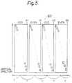
- Fig. 3shows a profile of input image signals 201 which are scanned by the interlaced scanning method, wherein the odd and even fields are alternately applied.
- Fig. 3shows the fields in the coordinates where time is plotted on the horizontal axis and vertical direction on the vertical axis.
- K1indicates an odd field of the first frame, while G1, an even field of the first frame.
- K2is an odd field of the second frame, while G2, an even field of the second frame.
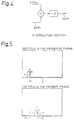
- Fig. 4is a block diagram of an example of the interpolating section 20.
- a simple arithmetic mean of the motion compensated prediction signal 204a from the inputted odd fields and the motion compensated prediction signal 204b from the inputted even fieldsis obtained and is used as an interpolation predictive signal 204c.
- Motion of the odd fields and even fields of the present frame in relation to the preceding frameis detected in units of blocks including pixels (n x m) in response to the input image signal 201 which is scanned by the interlace scanning method and includes the odd and even fields alternately.
- the motion of the odd fields between the present and the preceding framesis detected by searching, in the motion detecting section 22, the block which most resembles the currently processed block in the image signal 201 from the blocks adjacent 202a to the position corresponding to the currently encoded object in the already encoded odd fields stored within the odd field memory 28.
- Fig. 5As shown in Fig. 5, for example, it is assumed that image H1 exists within one block unit (n x m) in the preceding frame, and the image moves to position H2 from position H1 in the present input image signal.
- the motion detecting section 22outputs a motion vector 203 which indicates the block has moved horizontally to H2 from H1. In this case, since motion is not detected in the vertical direction, the motion vector 203 has the value of 0 with regard to vertical direction. The motion in the horizontal and vertical directions thus obtained is outputted as the motion vector 203.
- the odd field memory 28outputs a motion compensated prediction signal 204a corresponding to this motion vector 203.
- compensation for motion of the even fields in the preceding frameis carried out in the motion detecting section 22, by searching the block resembling the currently processed block from the adjacent blocks 202b within the even field memory 29 and outputting the result as the motion vector 203.
- the motion compensated prediction signal 204b corresponding to this motion vector 203is outputted from the even field memory 29.
- the interpolation processingis carried out in the interpolating section 20 shown in Fig. 4, by using the motion compensated prediction signals 204a and 204b to generate the interpolation predictive signal 204c, signal 204a being generated by motion compensated in accordance with the motion vector 203 and provided from the odd field memory 28, and motion compensated predictive signal 204b being generated by motion compensated in accordance with the motion vector 203 and provided from the second field memory 9.
- a predictive signal having the minimum error signal power with respect to the currently encoding object block of the input image signal 201is selected by the selector 21 from among the motion compensated prediction signal 204a obtained from the odd field, the motion compensated prediction signal 204b obtained from the even field, and the interpolated motion compensated prediction signal 204c, and then the predictive signal 210 is produced.
- Fig. 6is a diagram showing the operation explained above. It is assumed that the odd field memory 28 shown in Fig. 2 stores an odd field K1 of the preceding (previous) frame, while the even field memory 29 of Fig. 2 stores an even field G1 of the preceding frame. Here, the case where an odd field K2 and an even field G2 are included in the current (present) frame of the input image signal 201 will be discussed.
- the odd field K2is inputted, the motion compensated prediction signal 204a from the odd field K1 of the preceding frame stored in the odd field memory 28 is provided to the selector 21.
- the even field G1 of the preceding frame stored in the even field memory 29is provided to the selector 21 as the motion compensated prediction signal 204b.
- the data of K1 and G1are applied to the interpolating section 20 and the interpolation processing as shown in Fig. 4 is conducted. Thereafter, such data is supplied to the selector 21 as the motion compensated prediction signal 204c.
- the selector 21compares these three kinds of motion compensated prediction signals 204a, 204b, 204c and the input image signal 201 to select the prediction signal which has the minimum error signal power.
- the selector 21is responsive to the even field G2 of the current frame to receive the prediction signal 204a based on the odd field K1 stored in the odd field memory 28, the motion compensated prediction signal 204b based on the even field G1 stored in the even field memory 29, and the motion compensated prediction signal 204c obtained by the interpolation process on the basis of these motion compensated prediction signals 204a, 204b based on both fields, and to select the prediction signal which has the minimum error signal power.
- the interpolation sectionis provided to conduct the interpolation processing based on the motion compensated prediction signals 204a, 204b from the odd field memory 28 and even field memory 29 and thereby motion compensated prediction signal 204c is produced.
- the interpolation section 20is not used as shown in Fig. 7.
- the motion compensated prediction signalis generated in the selector 21 on the basis of the preceding odd field K1 stored in the odd field memory 28 and the preceding even field G1 stored in the even field memory 29 and the selector 21 selects the prediction signal minimizing the error signal power in these two kinds of motion compensated prediction signals 204a, 204b.
- the simple arithmetic meanhas been used for the interpolation section, but coding ensuring higher prediction efficiency can be realized by utilizing a weighted arithmetic mean taking into consideration field distance, as will be explained hereunder with reference to Fig. 8.
- Fig. 8is a block diagram of an example of the interpolation circuit 20.
- the motion compensated prediction signal 204a from the odd fieldis multiplied by a weight ⁇ based on the distance to the field to be encoded
- the motion compensated prediction signal 204b from the even fieldis multiplied by a weight ⁇ based on the distance to the field to be encoded. Thereafter, the arithmetic mean of these values is obtained and the output thereof is used as interpolation predictive signal 204c.
- the weights ⁇ and ⁇can be determined by utilizing such time differences. For example, since the odd field K1 has a time distance of 2T, the weight ⁇ is set to 1. Also, since even field G1 has a time distance of T from odd field K2, the value of weight can be increased for the field having the lesser time distance by setting the value of ⁇ to 2.
- odd field K1has a time distance of 3T from even field G2 and even field G1 has a time difference of 2T.
- istis possible to give the value of weight which is proportional to the time difference by setting ⁇ to 2 and ⁇ to 3 for weighting even field G2.
- the weights ⁇ and ⁇are determined in the interpolating section on the basis of time distance.
- the weight ⁇ to be given to the odd fieldis always set, for example, larger or smaller than weight ⁇ to be given to the even field regardless of the time distance.
- weights ⁇ and ⁇ used for the odd fieldsare different from those used for the even fields, but the weights for the odd fields may be equal to those for the even fields.
- only weights ⁇ and ⁇are used, but the weights may be determined in accordance with the other coefficients, for example, a coefficient having a quadratic function or another function having particular characteristics.
- weights ⁇ and ⁇do not have to be restricted only to one kind of value; it is possible that several kinds of weights ⁇ and ⁇ are prepared and selected in accordance with the kind of input signal or the characteristic of input signal.
- the embodiment shown in Fig. 9comprises a blocking selection section 82 for selecting between an individual blocking of a prediction error signal for the odd and even fields and a non-interlace blocking including both odd and even fields; a blocking forming section 83 for conducting the blocking in accordance with the output of the blocking selection section 82; and a blocking decomposing section 84 for decomposing the blocking to form the original field in accordance with the block selection output.
- Section 400 enclosed by a broken linedenotes blocking means and the other sections 200, 300, 500 are similar to those shown in Fig. 2.
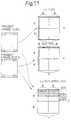
- Fig. 10is a block diagram of an example of the blocking selection section 82.
- the prediction error signal 205is stored in the oddd field memory 31 for the odd field and in the evend field memory 32 for the even field.
- the individual field blocking section 33executes the blocking including the pixels of either of the odd or even field within the block of (p pixels x q lines), and these pixels are encoded in a coding section 35.
- a non-interlace blocking section 34executes the blocking of (p pixels x q lines) included in the block by alternately arranging the pixels of both odd and even fields, and these pixels are encoded in a coding circuit 36.
- the information quantity comparing section 37compares the quantity of data encoded in the coding section 35 and the coding circuit 36, and outputs a blocking selection signal 211 indicating the blocking having the least amount of information.
- Fig. 12is a block diagram of an example of the blocking forming section 83.
- the prediction error signal 205is stored in the odd field memory 41 for the odd field and in the even field memory 42 for the even field.
- the blocking forming section 43selects the blocking of the prediction error signals stored in the odd field memory 41 and even field memory 42 from the blocking including pixels of either of the odd or even field within the block of (p pixels x q lines) and the blocking including pixels of both odd and even fields within the block of (p pixels x q lines), and then outputs the blocked prediction error signal.
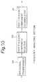
- Fig. 13is a block diagram of an example of the blocking decomposing section 84.
- the data decoded by a local decoding circuit 25is applied to the blokking decomposing section 44 in which the blocking is decomposed in accordance with the blocking selection signal 211 from the blocking selection section 82, and the decomposed block is then stored in the individual field memories 45, 46.
- the stored datais supplied as a decoded error signal 207.
- the prediction error signal 205 obtained by subtracting the prediction signal 210 from an input signal 201 in a difference circuit 23is sent to the blocking forming section 83 shown in Fig. 12 and to the blocking selection section 82 shown in Fig. 10.
- the blocking selection section 82produces the blocking selection signal 211 for selecting the blocking including the pixels of either the odd or even field in the block of (p pixels x q lines), or the blocking including the pixels of both odd and even fields in the block of (p pixels x q lines).
- the blocking forming section 83conducts individual field blocking or non-interlace blocking in units of (p x q) blocks in accordance with the blocking selection signal 211.
- the blocked signalis applied to the coding circuit 24.
- the coding section 24execute the orthogonal transform and sends the encoded data 206 which is a scalar-quantized transform coefficient to both the local decoding section 25 and the multiplexing section 28.
- the datais decomposed into the odd and even fields in the blocking decomposing section shown in Fig. 13 which decomposes the blocking into the fields in accordance with the blocking selection signal 211 in order to obtain the decoded difference signal 207.
- the local decoded signal 208 obtained by adding a predictive signal 210 to the decoded difference siganl 207 in the adder 207is stored in the first field memory 28 when it is the odd field or in the second field memory 29 when it is the even field, to detect the motion of each field of the next frame.
- the size of 16 pixels x 16 lines combining four block unitsis selected as the values of p and q in the blocking forming section.
- pn
- n16 pixels.
- q2m
- m8.
- it is possible to employ the blocking combining the odd field and even field in the blocking forming sectionit is desirable to form a block fo 16 lines including the odd and even fields.
- the blockinghas been selectedd by comparing the quantity of information generated as shown in Fig. 10, but coding based on the quality of encoding can be realized by selecting the blocking on the basis of the comparison of encoding quality as shown in Fig. 14.
- Fig. 14is a block diagram of an example of the blocking selection section 82.
- the predicting error signal 205is stored in the odd field memory 51 for the odd field and in the even field memory 52 for the even field.
- the individual field blocking section 53realizes the blocking including the pixels of either the odd field or the even field within the block of (p pixels x q lines), and the coding/decoding section 55 enables encoding/decoding.
- the non-interlace blocking section 54realizes the blocking including the pixels of both fields within the block of (p pixels x q lines), and the coding/decoding circuit 56 enables coding/decoding.
- the difference between the encoded/decoded data of the individual field blocking and the data just before the encodingis compared with the difference between the encoded/decoded data of the combined field blocking and the data just before the encoding, by the error comparator 59 in order to select the blocking with less errors and to provide an output as the blocking selection signal 211.
- Fig. 15is a block diagram of an example of the blocking selection circuit 82.
- the predicting error signal 205is stored in the odd field memory 61 for the odd field and in the even field memory 62 for the even field.
- the individual field blocking section 63executes the blocking including the pixels of only either the odd field or even field within the block of (p pixels x q lines), and a frequency analyzing section 65 such as that shown in Fig. 16 executes the frequency analysis.
- the non-interlace blocking circuit 64executes the blocking including pixels of both fields within the block of (p pixels x q lines), and a frequency analyzing circuit 66 such as that shown in Fig. 16 executes the frequency analysis.
- the blocking with fewer high-frequency componentsis selected from the individual field blocking and the combined field blocking to output the blocking selection signal 211.
- Fig. 16is a block diagram of an example of the frequency analyzing sections 65 and 66.
- the signal obtained by individually blocking the odd and even fields from the individual field blocking circuit 63, and the signal obtained by blocking the pixels of both odd and even fields from the non-interlace blocking section 64,are supplied to sections 65 and 66. These signals are converted to a signal in the frequency domain from a signal in the pixel domain using the orthogonal transform 68.
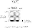
- the high-frequency componentsare extracted from the converted signal in the frequency domain by a high-frequency component selector 69 and the extracted high-frequency components are totaled by a high-frequency component accumulator 70.
- the accumulated high-frequency componentsare compared in a high-frequency component comparing section 67 to select the blocking with fewer amount high-frequency components.
- Fig. 17shows an example of the components accumulated by the high-frequency component adder 70 from the orthogonal transformed frequency domain signal.
- eight componentsfor example, having the maximum frequency component in the vertical frequency component, are selected.
- the coding section 24does not use the selection information of predictive signals or the selection information of blocking, but according to another embodiment shown in Fig. 18, finer control is possible and high encoding quality can be realized by inputting an output of the selector 11 as the selection signal for the predictive signal and the blocking selection signal as the selection signal for the blocking to the coding section 24 and by controlling the encoding characteristic with the selected prediction signal and the information of the selected blocking.
- the embodiment of Fig. 2relates to a system for realizing predictive coding of an input image signal obtained by the interlaced scanning method with the motion compensation.
- the systemincludes motion detecting means for obtaining, for the odd or even field of the input image signal, the amount of displacement, in order to carry out the individual motion compensated prediction, in units of the block of (n pixels x m lines) (n and m: positive integer) from both the odd and even fields of the already encoded frame, and the prediction error signal output means for selecting, with a selector 21, the predictive signal indicating the optimum prediction from signals including a first predictive signal 204a obtained by the motion compensation from the odd field, a second predictive signal 204d obtained by the motion compensation from the even field, and a third predictive signal 204c obtained by interpolating the first and second predictive signals in order to obtain the difference from the field of the input signal and output the result as the prediction error signal.
- Fig. 2is an adaptive field/frame coding system characterized in that the interpolation means for obtaining the third predictive signal is the simple arithmetic mean of the first predictive signal and the second predictive signal.
- the hardwarecan be minimized in size and encoding with higher prediction efficiency can be realized by generating an interpolation signal of the predictive signal by simply obtaining the arithmetic mean of both predicted odd and even fields with motion compensation.
- the embodiment of Fig. 8is an adaptive field/frame coding system characterized in that the interpolation means for obtaining the third predictive signal is the weighted arithmetic mean of the first predictive signal and the second predictive signal, also considering the time distance of the field used for the prediction and the field to be encoded.
- the embodiment shown in Fig. 9is an adaptive field/frame coding system comprising means for enabling encoding by selecting blocking including the pixels of either the odd field or even field within the block of (p pixels x q lines), or blocking including the pixels of both odd and even fields within the block of (p pixels x q lines), in order to encode the prediction error signal for the odd and even fields of the input image signal in units of the block of (p pixels x q lines) (p and q: positive integer).
- the embodiment shown in Fig. 9is an adaptive field/frame coding system characterized in that the blocking means for enabling encoding while selecting the blocks comprises selecting means for selecting the blocking with less information for encoding from blocking including the pixels of only one of the odd field and even field within the block of (p pixels x q lines), and blocking including the pixels of both odd and even fields within the block of (p pixels x q lines).
- the embodiment shown in Fig. 14is an adaptive field/frame coding system characterized in that the blocking means for enabling encoding while selecting the blocks comprises means for selecting the blocking with less encoding error from blocking including the pixels of only one of the odd field and even field within the block of (p pixels x q lines), and blocking including the pixels of both odd and even fields within the block of (p pixels x q lines).
- the embodiment shown in Fig. 15is an adaptive field/frame coding system characterized in that the blocking means for enabling encoding while selecting the blocks comprises selecting means for selecting the blocking with less high-frequency components included in the signal to be encoded from blocking including the pixels of only one of the odd field and even field within the block of (p pixels x q lines), and blocking including the pixels of both odd and even fields within the block of (p pixles x q lines).
- the embodiment shown in Fig. 18is an adaptive field/frame coding system characterized by enabling encoding while selecting the quantization characteristic of the transform coefficient in accordance with the selected predictive signal and the selected blocking, in the case of employing the orthogonal transformer and carrying out encoding by the quantization of transform ceofficient in the coding section for the encoding in units of the block of (p pixels x q lines).
- an input image signal 201is formed of the frame including the odd field and even field.
- the use of the odd field and even fieldis intended to show only an example, and the field is not restricted to the odd or even field.
- the present inventioncan be useful whenever one frame is divided into fields, the odd field and even field being only examples of such fields of a frame.
- the present inventioncan also be applied to a case of storing data by dividing the frame into two fields every two lines by, for example defining the first field as the 1st and 2nd lines and the second field as the 3rd and 4th lines, and defining the first field as the 5th and 6th lines and the second field as the 7th line and 8th line, etc.
- the present inventioncan also be applied to the case of dividing a frame into more than two fields, for example, three or four kinds of fields.
- the number of field memoriescorresponds to the number of kinds of fields, and the processing explained above is carried out for each field.
- the blocking selection sectionselects the blocking from two kinds of blocking, including the blocking of the pixels of only one of the odd field and even field and the blocking of the pixels of both odd and even fields.
- the blockingmay include various combinations when two or more fields are prepared in addition to the odd and even fields.
- the blocks shown in Figs. 11(a), (b), (c)are only examples and various block forming methods may be used to form the block other than the blocks of Fig. 11.
- the blocking means shown in Fig. 9is used with the prediction error signal output means and motion detecting means. Even if the sections other than the blocking means 400 are replaced with conventional means, the 3rd and 4th aspects explained above can be provided.
- a stable encoded image with high efficiencycan be obtained by individually searching the motion from each field of the already encoded frame to predict each field and by conducting adaptive prediction from the searched motion compensated predictive signals (and interpolation signals).
- a stabled encoded image with high efficiencycan also be obtained by adaptively selecting the encoding from the blocking of the pixels of only one of the fields of the frame to be encoded, and the encoding after conducting the blocking of the pixels of the respective fields when encoding the prediction error signal.
Landscapes
- Engineering & Computer Science (AREA)
- Multimedia (AREA)
- Signal Processing (AREA)
- Compression Or Coding Systems Of Tv Signals (AREA)
- Color Television Systems (AREA)
- Iron Core Of Rotating Electric Machines (AREA)
- Compression, Expansion, Code Conversion, And Decoders (AREA)
- Closed-Circuit Television Systems (AREA)
- Reduction Or Emphasis Of Bandwidth Of Signals (AREA)
- Television Systems (AREA)
- Image Processing (AREA)
- Superconductors And Manufacturing Methods Therefor (AREA)
- Burglar Alarm Systems (AREA)
- Design And Manufacture Of Integrated Circuits (AREA)
- Networks Using Active Elements (AREA)
Abstract
Description
- Fig. 1
- is a block diagram showing the structureof a coding system of the priorart;
- Fig. 2
- is a block diagram showing the structureof an adaptive field/frame codingsystem of an embodiment of the presentinvention;
- Fig. 3
- is a diagram showing a exemplary inputimage signal;
- Fig. 4
- is a block diagram showing an exampleof the structure of an interpolatingsection shown in Fig. 2;
- Fig. 5
- is a diagram for explaining the operationof a motion detecting circuit;
- Fig. 6
- is a diagram for explaining the operationfor using a motion compensatedpredictive signal in the embodimentshown in Fig. 2;
- Fig. 7
- is a block diagram showing the structureof an adaptive field/frame codingsystem according to another embodimentof the present invention;
- Fig. 8
- is a block diagram showing anotherexample of the interpolating section;
- Fig. 9
- is a block diagram showing an adaptivefield/frame coding system according toembodiment of the present invention;
- Fig. 10
- is a block diagram showing an exampleof the structure of the blocking selectionsection;
- Fig. 11
- is a diagram showing a structuralexample of the block selected by theblocking selecting section;
- Fig. 12
- is a block diagram showing a structuralexample of the blocking formingsection;
- Fig. 13
- is a block diagram showing a structuralexample of the blocking decomposingsection;
- Fig. 14
- is a block diagram showing anotherstructural example of the blockingselecting section;
- Fig. 15
- is a block diagram showing anotherstructural example of the blockingselecting section;
- Fig. 16
- is a block diagram showing a structuralexample of the frequency analyzingsection;
- Fig. 17
- is a diagram showing an example of theaccumulated frequency components; and
- Fig. 18
- is a block diagram showing anotherstructural example of the present invention.
Claims (6)
- A coding system comprising:(a) input means for inputting an input signalto be encoded;(b) a field memory for storing the input signalby dividing said signal into a plurality offields such as the odd field and evenfield;(c) predictive signal output means for outputtinga plurality of predictive signals predictingthe change of input signal correspondedto each signal storeds in saidfield memory;(d) a selector for selecting a predictive signalfrom the predictive signals providedby said predictive signal output means; and(e) coding means for encoding the input signalusing the relationship between said predictivesignal selected by said selector andthe input signal from said input means.
- A coding system according to claim 1 furthercomprising an interpolation means for outputtingan interpolated predictive signal in response topredictive signals of a plurality of types fromsaid predictive signal output means.
- The coding system according to claim 1 furthercomprising:a blocking selector for selecting, at the timeof encoding the predictive error signal, a blocksuitable for encoding, the block being selectedfrom a block comprising a signal of one kind of field, and a block comprising a signal from combiningsignals of a plurality of fields; anda block former for forming said block selectedby said blocking selector.
- The coding system according to claim 3, whereinsaid blocking selector comprises selecting meansselected from the group consisting of thefollowing:first selecting means for selecting, from a pluralityof kinds of blocks, the block with theleast amount of encoding information generated;second selecting means for selecting, from aplurality of kinds of blocks, the block with theleast amount of encoding errors; andthird selecting means for selecting, from a pluralityof kinds of blocks, the block with theleast amount of high-frequency components containedin the signal to be encoded.
- A coding system according to claim 2, whereinsaid interpolation means produces the interpolatedsignal by computing the arithmetic mean ofthe plurality of predictive signals.
- A coding system according to claim 2, whereinsaid interpolation means produces the interpolatedsignal by computing the arithmetic mean ofthe plurality of predictive signals weighted bypredetermined weighting factors.
Priority Applications (5)
| Application Number | Priority Date | Filing Date | Title |
|---|---|---|---|
| EP19990124383EP0984635B1 (en) | 1991-10-22 | 1992-10-21 | Predictive video coding system |
| EP03000329AEP1309202B8 (en) | 1991-10-22 | 1992-10-21 | Video coding system |
| EP20000127405EP1091589B1 (en) | 1991-10-22 | 1992-10-21 | Coding system |
| EP19990124382EP0986263A3 (en) | 1991-10-22 | 1992-10-21 | Predictive video coding system |
| EP19990124384EP0984636B1 (en) | 1991-10-22 | 1992-10-21 | Predictive video coding system |
Applications Claiming Priority (7)
| Application Number | Priority Date | Filing Date | Title |
|---|---|---|---|
| JP27384391AJP2586260B2 (en) | 1991-10-22 | 1991-10-22 | Adaptive blocking image coding device |
| JP273843/91 | 1991-10-22 | ||
| JP27384391 | 1991-10-22 | ||
| JP8065492 | 1992-04-02 | ||
| JP8065492AJP2924431B2 (en) | 1991-10-22 | 1992-04-02 | Coding method |
| JP80654/92 | 1992-04-02 | ||
| EP19920118018EP0538834B1 (en) | 1991-10-22 | 1992-10-21 | Image signal coding system |
Related Parent Applications (1)
| Application Number | Title | Priority Date | Filing Date |
|---|---|---|---|
| EP19920118018DivisionEP0538834B1 (en) | 1991-10-22 | 1992-10-21 | Image signal coding system |
Related Child Applications (8)
| Application Number | Title | Priority Date | Filing Date |
|---|---|---|---|
| EP19990124384DivisionEP0984636B1 (en) | 1991-10-22 | 1992-10-21 | Predictive video coding system |
| EP19990124384Division-IntoEP0984636B1 (en) | 1991-10-22 | 1992-10-21 | Predictive video coding system |
| EP19990124383DivisionEP0984635B1 (en) | 1991-10-22 | 1992-10-21 | Predictive video coding system |
| EP19990124383Division-IntoEP0984635B1 (en) | 1991-10-22 | 1992-10-21 | Predictive video coding system |
| EP19990124382DivisionEP0986263A3 (en) | 1991-10-22 | 1992-10-21 | Predictive video coding system |
| EP19990124382Division-IntoEP0986263A3 (en) | 1991-10-22 | 1992-10-21 | Predictive video coding system |
| EP20000127405DivisionEP1091589B1 (en) | 1991-10-22 | 1992-10-21 | Coding system |
| EP20000127405Division-IntoEP1091589B1 (en) | 1991-10-22 | 1992-10-21 | Coding system |
Publications (3)
| Publication Number | Publication Date |
|---|---|
| EP0825780A2true EP0825780A2 (en) | 1998-02-25 |
| EP0825780A3 EP0825780A3 (en) | 1999-06-02 |
| EP0825780B1 EP0825780B1 (en) | 2001-09-19 |
Family
ID=26421636
Family Applications (7)
| Application Number | Title | Priority Date | Filing Date |
|---|---|---|---|
| EP19990124383Expired - LifetimeEP0984635B1 (en) | 1991-10-22 | 1992-10-21 | Predictive video coding system |
| EP03000329ARevokedEP1309202B8 (en) | 1991-10-22 | 1992-10-21 | Video coding system |
| EP19990124384Expired - LifetimeEP0984636B1 (en) | 1991-10-22 | 1992-10-21 | Predictive video coding system |
| EP19920118018Expired - LifetimeEP0538834B1 (en) | 1991-10-22 | 1992-10-21 | Image signal coding system |
| EP19990124382WithdrawnEP0986263A3 (en) | 1991-10-22 | 1992-10-21 | Predictive video coding system |
| EP19970113971Expired - LifetimeEP0825780B1 (en) | 1991-10-22 | 1992-10-21 | Coding system |
| EP20000127405Expired - LifetimeEP1091589B1 (en) | 1991-10-22 | 1992-10-21 | Coding system |
Family Applications Before (5)
| Application Number | Title | Priority Date | Filing Date |
|---|---|---|---|
| EP19990124383Expired - LifetimeEP0984635B1 (en) | 1991-10-22 | 1992-10-21 | Predictive video coding system |
| EP03000329ARevokedEP1309202B8 (en) | 1991-10-22 | 1992-10-21 | Video coding system |
| EP19990124384Expired - LifetimeEP0984636B1 (en) | 1991-10-22 | 1992-10-21 | Predictive video coding system |
| EP19920118018Expired - LifetimeEP0538834B1 (en) | 1991-10-22 | 1992-10-21 | Image signal coding system |
| EP19990124382WithdrawnEP0986263A3 (en) | 1991-10-22 | 1992-10-21 | Predictive video coding system |
Family Applications After (1)
| Application Number | Title | Priority Date | Filing Date |
|---|---|---|---|
| EP20000127405Expired - LifetimeEP1091589B1 (en) | 1991-10-22 | 1992-10-21 | Coding system |
Country Status (13)
| Country | Link |
|---|---|
| US (13) | US5274442A (en) |
| EP (7) | EP0984635B1 (en) |
| JP (2) | JP2586260B2 (en) |
| KR (1) | KR950011197B1 (en) |
| AT (3) | ATE236492T1 (en) |
| AU (2) | AU652490B2 (en) |
| CA (4) | CA2234391C (en) |
| DE (6) | DE69229210T2 (en) |
| DK (6) | DK0825780T3 (en) |
| ES (6) | ES2242104T3 (en) |
| FI (5) | FI111591B (en) |
| NO (2) | NO310849B1 (en) |
| SG (1) | SG65597A1 (en) |
Families Citing this family (134)
| Publication number | Priority date | Publication date | Assignee | Title |
|---|---|---|---|---|
| JP2586260B2 (en)* | 1991-10-22 | 1997-02-26 | 三菱電機株式会社 | Adaptive blocking image coding device |
| JP3165296B2 (en)* | 1992-12-25 | 2001-05-14 | 三菱電機株式会社 | Inter-frame coding processing method, inter-frame coding processing method, and coding control method |
| US5915040A (en)* | 1993-03-29 | 1999-06-22 | Canon Kabushiki Kaisha | Image processing apparatus |
| BE1007252A3 (en)* | 1993-06-29 | 1995-05-02 | Philips Electronics Nv | Motion compensator. |
| JPH0787448A (en)* | 1993-06-30 | 1995-03-31 | Victor Co Of Japan Ltd | Coding circuit and decoding circuit for digital video signal |
| JP3202433B2 (en)* | 1993-09-17 | 2001-08-27 | 株式会社リコー | Quantization device, inverse quantization device, image processing device, quantization method, inverse quantization method, and image processing method |
| FR2711879B1 (en)* | 1993-10-22 | 1995-12-15 | Thomson Csf | Interframe coding method and device with rate control for recording images on a VCR. |
| US6243139B1 (en)* | 1993-12-22 | 2001-06-05 | Canon Kabushiki Kaisha | Apparatus for block-encoding input image signals |
| TW283289B (en)* | 1994-04-11 | 1996-08-11 | Gen Instrument Corp | |
| US5719961A (en)* | 1994-07-22 | 1998-02-17 | Apple Computer, Inc. | Adaptive technique for encoder and decoder signal transformation |
| JPH0865681A (en)* | 1994-08-25 | 1996-03-08 | Sony Corp | Motion vector detector and motion compensating prediction encoding system using the detector |
| US5596376A (en)* | 1995-02-16 | 1997-01-21 | C-Cube Microsystems, Inc. | Structure and method for a multistandard video encoder including an addressing scheme supporting two banks of memory |
| US5774593A (en)* | 1995-07-24 | 1998-06-30 | University Of Washington | Automatic scene decomposition and optimization of MPEG compressed video |
| JP2962348B2 (en)* | 1996-02-08 | 1999-10-12 | 日本電気株式会社 | Image code conversion method |
| US6542642B2 (en)* | 1996-02-29 | 2003-04-01 | Canon Kabushiki Kaisha | Image coding process and motion detecting process using bidirectional prediction |
| JP3111028B2 (en) | 1996-03-14 | 2000-11-20 | 松下電器産業株式会社 | Image signal processing apparatus and image signal processing method |
| KR100318060B1 (en)* | 1997-01-30 | 2002-02-19 | 모리시타 요이찌 | Digital image replenishment method, image processing device and data recording medium |
| JPH10234014A (en)* | 1997-02-20 | 1998-09-02 | Matsushita Electric Ind Co Ltd | Image decoding method, image decoding device, image multiplexing method, image multiplexing device, and recording medium |
| JPH10262244A (en)* | 1997-03-18 | 1998-09-29 | Fujitsu Ltd | Still picture coding device |
| JP3604864B2 (en)* | 1997-04-25 | 2004-12-22 | シャープ株式会社 | Video encoding device |
| US6108383A (en)* | 1997-07-15 | 2000-08-22 | On2.Com, Inc. | Method and apparatus for compression and decompression of video images |
| JPH11122613A (en)* | 1997-10-16 | 1999-04-30 | Matsushita Electric Ind Co Ltd | Video signal processing apparatus and video signal processing method |
| US5973743A (en)* | 1997-12-02 | 1999-10-26 | Daewoo Electronics Co., Ltd. | Mode coding method and apparatus for use in an interlaced shape coder |
| AU749635B2 (en) | 1998-02-13 | 2002-06-27 | Quvis, Inc. | Apparatus and method for optimized compression of interlaced motion images |
| US20020044692A1 (en)* | 2000-10-25 | 2002-04-18 | Goertzen Kenbe D. | Apparatus and method for optimized compression of interlaced motion images |
| US6408029B1 (en) | 1998-04-02 | 2002-06-18 | Intel Corporation | Method and apparatus for simplifying real-time data encoding |
| US7046734B2 (en)* | 1998-04-02 | 2006-05-16 | Intel Corporation | Method and apparatus for performing real-time data encoding |
| US6904174B1 (en)* | 1998-12-11 | 2005-06-07 | Intel Corporation | Simplified predictive video encoder |
| US6999047B1 (en)* | 1998-08-12 | 2006-02-14 | Koninklijke Philips Electronics N.V. | Displaying video on a plasma display panel |
| US6243140B1 (en)* | 1998-08-24 | 2001-06-05 | Hitachi America, Ltd | Methods and apparatus for reducing the amount of buffer memory required for decoding MPEG data and for performing scan conversion |
| KR20000021867A (en)* | 1998-09-30 | 2000-04-25 | 전주범 | Method for encoding motion vector of binary form signal |
| US6983018B1 (en) | 1998-11-30 | 2006-01-03 | Microsoft Corporation | Efficient motion vector coding for video compression |
| US20030142875A1 (en)* | 1999-02-04 | 2003-07-31 | Goertzen Kenbe D. | Quality priority |
| US20030185455A1 (en)* | 1999-02-04 | 2003-10-02 | Goertzen Kenbe D. | Digital image processor |
| US6499060B1 (en) | 1999-03-12 | 2002-12-24 | Microsoft Corporation | Media coding for loss recovery with remotely predicted data units |
| DE10035109B4 (en)* | 1999-07-20 | 2012-03-08 | Lg Information & Communications, Ltd. | Terminal and method for transporting still images |
| EP1081959B1 (en)* | 1999-09-03 | 2007-11-14 | STMicroelectronics S.r.l. | Method for recognizing a progressive or an interlaced content in a video sequence |
| US6633612B2 (en)* | 2000-12-13 | 2003-10-14 | Genesis Microchip Inc. | Method and apparatus for detecting motion between odd and even video fields |
| FR2832271A1 (en)* | 2001-11-13 | 2003-05-16 | Koninkl Philips Electronics Nv | TUNER INCLUDING A VOLTAGE CONVERTER |
| US7027982B2 (en)* | 2001-12-14 | 2006-04-11 | Microsoft Corporation | Quality and rate control strategy for digital audio |
| US7003035B2 (en) | 2002-01-25 | 2006-02-21 | Microsoft Corporation | Video coding methods and apparatuses |
| US20040001546A1 (en) | 2002-06-03 | 2004-01-01 | Alexandros Tourapis | Spatiotemporal prediction for bidirectionally predictive (B) pictures and motion vector prediction for multi-picture reference motion compensation |
| US7016547B1 (en)* | 2002-06-28 | 2006-03-21 | Microsoft Corporation | Adaptive entropy encoding/decoding for screen capture content |
| US6980695B2 (en)* | 2002-06-28 | 2005-12-27 | Microsoft Corporation | Rate allocation for mixed content video |
| US7224731B2 (en)* | 2002-06-28 | 2007-05-29 | Microsoft Corporation | Motion estimation/compensation for screen capture video |
| US7280700B2 (en) | 2002-07-05 | 2007-10-09 | Microsoft Corporation | Optimization techniques for data compression |
| KR100865034B1 (en)* | 2002-07-18 | 2008-10-23 | 엘지전자 주식회사 | Method for predicting motion vector |
| US7154952B2 (en) | 2002-07-19 | 2006-12-26 | Microsoft Corporation | Timestamp-independent motion vector prediction for predictive (P) and bidirectionally predictive (B) pictures |
| EP1422946A4 (en)* | 2002-07-26 | 2008-04-02 | Matsushita Electric Industrial Co Ltd | ANIMAL IMAGE ENCODING METHOD, ANIMAL IMAGE DECODING METHOD, AND RECORDING MEDIUM |
| ES2334934T3 (en) | 2002-09-04 | 2010-03-17 | Microsoft Corporation | ENTROPY CODIFICATION BY ADAPTATION OF CODIFICATION BETWEEN LEVEL MODES AND SUCCESSION AND LEVEL LENGTH. |
| US7433824B2 (en) | 2002-09-04 | 2008-10-07 | Microsoft Corporation | Entropy coding by adapting coding between level and run-length/level modes |
| JP3791922B2 (en)* | 2002-09-06 | 2006-06-28 | 富士通株式会社 | Moving picture decoding apparatus and method |
| KR101039987B1 (en)* | 2002-10-01 | 2011-06-09 | 파나소닉 주식회사 | Picture decoding device, and method using the same |
| JP3960258B2 (en)* | 2003-04-28 | 2007-08-15 | ソニー株式会社 | Signal processing apparatus and signal processing method |
| US10554985B2 (en) | 2003-07-18 | 2020-02-04 | Microsoft Technology Licensing, Llc | DC coefficient signaling at small quantization step sizes |
| US7383180B2 (en) | 2003-07-18 | 2008-06-03 | Microsoft Corporation | Constant bitrate media encoding techniques |
| US20050013498A1 (en)* | 2003-07-18 | 2005-01-20 | Microsoft Corporation | Coding of motion vector information |
| US7609763B2 (en) | 2003-07-18 | 2009-10-27 | Microsoft Corporation | Advanced bi-directional predictive coding of video frames |
| US7499495B2 (en) | 2003-07-18 | 2009-03-03 | Microsoft Corporation | Extended range motion vectors |
| US7738554B2 (en) | 2003-07-18 | 2010-06-15 | Microsoft Corporation | DC coefficient signaling at small quantization step sizes |
| US7426308B2 (en) | 2003-07-18 | 2008-09-16 | Microsoft Corporation | Intraframe and interframe interlace coding and decoding |
| US7343291B2 (en) | 2003-07-18 | 2008-03-11 | Microsoft Corporation | Multi-pass variable bitrate media encoding |
| US7620106B2 (en) | 2003-09-07 | 2009-11-17 | Microsoft Corporation | Joint coding and decoding of a reference field selection and differential motion vector information |
| US7599438B2 (en) | 2003-09-07 | 2009-10-06 | Microsoft Corporation | Motion vector block pattern coding and decoding |
| US7688894B2 (en)* | 2003-09-07 | 2010-03-30 | Microsoft Corporation | Scan patterns for interlaced video content |
| US7577198B2 (en)* | 2003-09-07 | 2009-08-18 | Microsoft Corporation | Number of reference fields for an interlaced forward-predicted field |
| US7782954B2 (en)* | 2003-09-07 | 2010-08-24 | Microsoft Corporation | Scan patterns for progressive video content |
| US7577200B2 (en) | 2003-09-07 | 2009-08-18 | Microsoft Corporation | Extended range variable length coding/decoding of differential motion vector information |
| US7724827B2 (en) | 2003-09-07 | 2010-05-25 | Microsoft Corporation | Multi-layer run level encoding and decoding |
| US7567617B2 (en) | 2003-09-07 | 2009-07-28 | Microsoft Corporation | Predicting motion vectors for fields of forward-predicted interlaced video frames |
| US8064520B2 (en)* | 2003-09-07 | 2011-11-22 | Microsoft Corporation | Advanced bi-directional predictive coding of interlaced video |
| US7616692B2 (en) | 2003-09-07 | 2009-11-10 | Microsoft Corporation | Hybrid motion vector prediction for interlaced forward-predicted fields |
| US7623574B2 (en) | 2003-09-07 | 2009-11-24 | Microsoft Corporation | Selecting between dominant and non-dominant motion vector predictor polarities |
| US8085844B2 (en)* | 2003-09-07 | 2011-12-27 | Microsoft Corporation | Signaling reference frame distances |
| US7317839B2 (en) | 2003-09-07 | 2008-01-08 | Microsoft Corporation | Chroma motion vector derivation for interlaced forward-predicted fields |
| US7570818B2 (en)* | 2003-10-17 | 2009-08-04 | Hewlett-Packard Development Company, L.P. | Method for deblocking and transcoding a media stream |
| EP1727091A1 (en)* | 2004-02-27 | 2006-11-29 | Tdvision Corporation S.A. DE C.V. | Method and system for digital coding 3d stereoscopic video images |
| CA2557534A1 (en)* | 2004-02-27 | 2005-09-09 | Td Vision Corporation S.A. De C.V. | Method and system for digital decoding 3d stereoscopic video images |
| US8634413B2 (en) | 2004-12-30 | 2014-01-21 | Microsoft Corporation | Use of frame caching to improve packet loss recovery |
| US7693709B2 (en) | 2005-07-15 | 2010-04-06 | Microsoft Corporation | Reordering coefficients for waveform coding or decoding |
| US7599840B2 (en) | 2005-07-15 | 2009-10-06 | Microsoft Corporation | Selectively using multiple entropy models in adaptive coding and decoding |
| US7684981B2 (en) | 2005-07-15 | 2010-03-23 | Microsoft Corporation | Prediction of spectral coefficients in waveform coding and decoding |
| US9077960B2 (en) | 2005-08-12 | 2015-07-07 | Microsoft Corporation | Non-zero coefficient block pattern coding |
| US7565018B2 (en) | 2005-08-12 | 2009-07-21 | Microsoft Corporation | Adaptive coding and decoding of wide-range coefficients |
| US8599925B2 (en) | 2005-08-12 | 2013-12-03 | Microsoft Corporation | Efficient coding and decoding of transform blocks |
| US7933337B2 (en) | 2005-08-12 | 2011-04-26 | Microsoft Corporation | Prediction of transform coefficients for image compression |
| JP2008118239A (en)* | 2006-11-01 | 2008-05-22 | Canon Inc | IMAGING DEVICE AND IMAGING DEVICE CONTROL METHOD |
| CN101227601B (en)* | 2007-01-15 | 2011-09-14 | 飞思卡尔半导体公司 | Equipment and method for performing geometric transformation in video rendition |
| US8184710B2 (en) | 2007-02-21 | 2012-05-22 | Microsoft Corporation | Adaptive truncation of transform coefficient data in a transform-based digital media codec |
| JP4984983B2 (en)* | 2007-03-09 | 2012-07-25 | 富士通株式会社 | Encoding apparatus and encoding method |
| WO2008126225A1 (en)* | 2007-03-29 | 2008-10-23 | Pioneer Corporation | Moving image re-encoding apparatus and method |
| CN101647284B (en)* | 2007-04-20 | 2011-09-14 | 汤姆逊许可公司 | Method and apparatus for selecting scan paths for elements of blocks in spatial image encoding and decoding |
| US8031954B2 (en)* | 2007-04-26 | 2011-10-04 | Canon Kabushiki Kaisha | Image encoding apparatus and control method thereof using prediction encoding and pixel classification |
| US7774205B2 (en) | 2007-06-15 | 2010-08-10 | Microsoft Corporation | Coding of sparse digital media spectral data |
| US8254455B2 (en) | 2007-06-30 | 2012-08-28 | Microsoft Corporation | Computing collocated macroblock information for direct mode macroblocks |
| US8179974B2 (en) | 2008-05-02 | 2012-05-15 | Microsoft Corporation | Multi-level representation of reordered transform coefficients |
| US8325800B2 (en) | 2008-05-07 | 2012-12-04 | Microsoft Corporation | Encoding streaming media as a high bit rate layer, a low bit rate layer, and one or more intermediate bit rate layers |
| US8379851B2 (en) | 2008-05-12 | 2013-02-19 | Microsoft Corporation | Optimized client side rate control and indexed file layout for streaming media |
| US7925774B2 (en) | 2008-05-30 | 2011-04-12 | Microsoft Corporation | Media streaming using an index file |
| US8406307B2 (en) | 2008-08-22 | 2013-03-26 | Microsoft Corporation | Entropy coding/decoding of hierarchically organized data |
| US8311111B2 (en) | 2008-09-11 | 2012-11-13 | Google Inc. | System and method for decoding using parallel processing |
| US8326075B2 (en) | 2008-09-11 | 2012-12-04 | Google Inc. | System and method for video encoding using adaptive loop filter |
| US8325796B2 (en) | 2008-09-11 | 2012-12-04 | Google Inc. | System and method for video coding using adaptive segmentation |
| US8265140B2 (en) | 2008-09-30 | 2012-09-11 | Microsoft Corporation | Fine-grained client-side control of scalable media delivery |
| US8189666B2 (en) | 2009-02-02 | 2012-05-29 | Microsoft Corporation | Local picture identifier and computation of co-located information |
| US8599932B2 (en) | 2009-12-18 | 2013-12-03 | General Instrument Corporation | Carriage systems encoding or decoding JPEG 2000 video |
| US8638863B1 (en) | 2010-05-18 | 2014-01-28 | Google Inc. | Apparatus and method for filtering video using extended edge-detection |
| US9210442B2 (en) | 2011-01-12 | 2015-12-08 | Google Technology Holdings LLC | Efficient transform unit representation |
| US9380319B2 (en) | 2011-02-04 | 2016-06-28 | Google Technology Holdings LLC | Implicit transform unit representation |
| US8781004B1 (en) | 2011-04-07 | 2014-07-15 | Google Inc. | System and method for encoding video using variable loop filter |
| US8780971B1 (en) | 2011-04-07 | 2014-07-15 | Google, Inc. | System and method of encoding using selectable loop filters |
| US8780996B2 (en) | 2011-04-07 | 2014-07-15 | Google, Inc. | System and method for encoding and decoding video data |
| US9154799B2 (en) | 2011-04-07 | 2015-10-06 | Google Inc. | Encoding and decoding motion via image segmentation |
| US8885706B2 (en) | 2011-09-16 | 2014-11-11 | Google Inc. | Apparatus and methodology for a video codec system with noise reduction capability |
| JP5803500B2 (en)* | 2011-09-27 | 2015-11-04 | 株式会社Jvcケンウッド | Motion vector detection apparatus and method |
| US9100657B1 (en) | 2011-12-07 | 2015-08-04 | Google Inc. | Encoding time management in parallel real-time video encoding |
| US9262670B2 (en) | 2012-02-10 | 2016-02-16 | Google Inc. | Adaptive region of interest |
| US9131073B1 (en) | 2012-03-02 | 2015-09-08 | Google Inc. | Motion estimation aided noise reduction |
| US9344729B1 (en) | 2012-07-11 | 2016-05-17 | Google Inc. | Selective prediction signal filtering |
| US9219915B1 (en) | 2013-01-17 | 2015-12-22 | Google Inc. | Selection of transform size in video coding |
| US9967559B1 (en) | 2013-02-11 | 2018-05-08 | Google Llc | Motion vector dependent spatial transformation in video coding |
| US9544597B1 (en) | 2013-02-11 | 2017-01-10 | Google Inc. | Hybrid transform in video encoding and decoding |
| US9674530B1 (en) | 2013-04-30 | 2017-06-06 | Google Inc. | Hybrid transforms in video coding |
| US11425395B2 (en) | 2013-08-20 | 2022-08-23 | Google Llc | Encoding and decoding using tiling |
| US9392272B1 (en) | 2014-06-02 | 2016-07-12 | Google Inc. | Video coding using adaptive source variance based partitioning |
| US9578324B1 (en) | 2014-06-27 | 2017-02-21 | Google Inc. | Video coding using statistical-based spatially differentiated partitioning |
| US10102613B2 (en) | 2014-09-25 | 2018-10-16 | Google Llc | Frequency-domain denoising |
| US9565451B1 (en) | 2014-10-31 | 2017-02-07 | Google Inc. | Prediction dependent transform coding |
| US9769499B2 (en) | 2015-08-11 | 2017-09-19 | Google Inc. | Super-transform video coding |
| US10277905B2 (en) | 2015-09-14 | 2019-04-30 | Google Llc | Transform selection for non-baseband signal coding |
| US9807423B1 (en) | 2015-11-24 | 2017-10-31 | Google Inc. | Hybrid transform scheme for video coding |
| US9794574B2 (en) | 2016-01-11 | 2017-10-17 | Google Inc. | Adaptive tile data size coding for video and image compression |
| US10542258B2 (en) | 2016-01-25 | 2020-01-21 | Google Llc | Tile copying for video compression |
| US11122297B2 (en) | 2019-05-03 | 2021-09-14 | Google Llc | Using border-aligned block functions for image compression |
Family Cites Families (59)
| Publication number | Priority date | Publication date | Assignee | Title |
|---|---|---|---|---|
| AT361699B (en)* | 1979-06-11 | 1981-03-25 | Schelling & Co | COLORFUL PLANT FOR PANEL-LIKE WORKPIECES |
| JPS57210785A (en)* | 1981-06-19 | 1982-12-24 | Kokusai Denshin Denwa Co Ltd <Kdd> | Adaptive forecasting system between frames of television signal |
| JPS5836090A (en)* | 1981-08-27 | 1983-03-02 | Kokusai Denshin Denwa Co Ltd <Kdd> | Median predictive coding method for television signals |
| JPS58127488A (en)* | 1982-01-25 | 1983-07-29 | Kokusai Denshin Denwa Co Ltd <Kdd> | Adaptive predictive coding method for television signals |
| JPS58137379A (en)* | 1982-02-10 | 1983-08-15 | Nec Corp | Interframe/interfield encoding device with motion compensation |
| JPH0746864B2 (en)* | 1984-08-22 | 1995-05-17 | ソニー株式会社 | High efficiency encoder |
| JPS6162286A (en)* | 1984-09-04 | 1986-03-31 | Univ Nagoya | Image signal band compression method |
| DE3684047D1 (en)* | 1985-07-02 | 1992-04-09 | Matsushita Electric Industrial Co Ltd | BLOCK CODING DEVICE. |
| JPS62102685A (en)* | 1985-10-29 | 1987-05-13 | Sony Corp | High-efficiency encoder |
| JP2612557B2 (en)* | 1985-12-18 | 1997-05-21 | ソニー株式会社 | Data transmission receiving system and data decoding device |
| JPS62145988A (en)* | 1985-12-20 | 1987-06-30 | Fujitsu Ltd | Adaptive scan line conversion image transmission method |
| US4736136A (en) | 1986-06-16 | 1988-04-05 | Gte Laboratories Incorporated | Discharge lamps with coated ceramic arc tubes and fabrication thereof |
| DE3642492A1 (en)* | 1986-12-12 | 1988-06-23 | Bosch Gmbh Robert | METHOD AND CIRCUIT ARRANGEMENT FOR REDUCING THE DATA RATE OF DIGITALIZED IMAGES |
| NL8700565A (en)* | 1987-03-10 | 1988-10-03 | Philips Nv | TV SYSTEM IN WHICH TRANSFORMED CODING TRANSFERS DIGITIZED IMAGES FROM A CODING STATION TO A DECODING STATION. |
| JP2637093B2 (en)* | 1987-03-13 | 1997-08-06 | 株式会社東芝 | Image coding method |
| US4783698A (en)* | 1987-04-13 | 1988-11-08 | Technology Inc., 64 | Interpolator for compressed video data |
| JPH01278184A (en)* | 1988-04-29 | 1989-11-08 | Nec Home Electron Ltd | Picture signal encoder |
| JPH0220082A (en)* | 1988-07-08 | 1990-01-23 | Nikon Corp | Discharge type excimer laser device |
| US4941045A (en)* | 1988-10-11 | 1990-07-10 | Scientific-Atlanta, Inc. | Method and apparatus for improving vertical definition of a television signal by scan conversion |
| JPH02200082A (en)* | 1989-01-30 | 1990-08-08 | Hitachi Ltd | Image encoder |
| JPH02226886A (en)* | 1989-02-28 | 1990-09-10 | Sony Corp | Data transmitter |
| JPH02266683A (en)* | 1989-04-07 | 1990-10-31 | Oki Electric Ind Co Ltd | Picture processing unit |
| JP2946531B2 (en) | 1989-05-29 | 1999-09-06 | ソニー株式会社 | Auto focus circuit |
| JP2562499B2 (en)* | 1989-05-29 | 1996-12-11 | 日本電信電話株式会社 | High-efficiency image encoding device and its decoding device |
| US4894812A (en) | 1989-06-29 | 1990-01-16 | Wood Eddie M | Removable and reusable cap with timepiece for a modified disposable cigarette lighter |
| JPH0832039B2 (en)* | 1989-08-19 | 1996-03-27 | 日本ビクター株式会社 | Variable length coding method and apparatus thereof |
| JPH0397320A (en)* | 1989-09-11 | 1991-04-23 | Matsushita Electric Ind Co Ltd | data compression device |
| JPH03252287A (en)* | 1990-02-28 | 1991-11-11 | Victor Co Of Japan Ltd | Moving picture compressor |
| US5046119A (en)* | 1990-03-16 | 1991-09-03 | Apple Computer, Inc. | Method and apparatus for compressing and decompressing color video data with an anti-aliasing mode |
| US5091782A (en)* | 1990-04-09 | 1992-02-25 | General Instrument Corporation | Apparatus and method for adaptively compressing successive blocks of digital video |
| US5068724A (en)* | 1990-06-15 | 1991-11-26 | General Instrument Corporation | Adaptive motion compensation for digital television |
| JPH0490799A (en)* | 1990-08-06 | 1992-03-24 | Matsushita Electric Ind Co Ltd | cordless iron |
| JPH0797540B2 (en)* | 1990-08-18 | 1995-10-18 | エルナー株式会社 | Method for ultrasonic welding of electrode foil and lead terminal of aluminum electrolytic capacitor and anvil used for this method |
| US5093720A (en)* | 1990-08-20 | 1992-03-03 | General Instrument Corporation | Motion compensation for interlaced digital television signals |
| JP2839358B2 (en)* | 1990-11-13 | 1998-12-16 | 松下電器産業株式会社 | Encoding device and method |
| JP3057746B2 (en)* | 1990-10-31 | 2000-07-04 | 日本ビクター株式会社 | Coding method for interlaced video |
| JP2830881B2 (en)* | 1991-03-18 | 1998-12-02 | 日本ビクター株式会社 | Predictive encoding method for interlaced image signals |
| EP0683615B1 (en)* | 1990-10-31 | 1999-05-19 | Victor Company Of Japan, Ltd. | Compression method for interlace moving image signals |
| GB9025518D0 (en)* | 1990-11-23 | 1991-01-09 | British Broadcasting Corp | Bandwidth reduction by switched filtering |
| US5193004A (en)* | 1990-12-03 | 1993-03-09 | The Trustees Of Columbia University In The City Of New York | Systems and methods for coding even fields of interlaced video sequences |
| FR2670348A1 (en)* | 1990-12-07 | 1992-06-12 | France Etat | IMAGE ENCODING DEVICE BELOW IMAGE SEQUENCE, LINING LINES BEFORE MATHEMATICAL TRANSFORMATION, IMAGE TRANSMISSION SYSTEM, RECEIVER AND CORRESPONDING ENCODING METHOD. |
| US5157747A (en)* | 1991-01-18 | 1992-10-20 | At&T Bell Laboratories | Photorefractive optical fiber |
| JPH04252690A (en)* | 1991-01-29 | 1992-09-08 | Matsushita Electric Ind Co Ltd | Video signal encoding method and video signal encoding device |
| NL9100234A (en)* | 1991-02-11 | 1992-09-01 | Philips Nv | CODING CIRCUIT FOR TRANSFORMING CODING OF AN IMAGE SIGNAL AND DECODING CIRCUIT FOR DECODING THEREOF. |
| US5083720A (en)* | 1991-04-03 | 1992-01-28 | Eastman Kodak Company | Film cassette with cooperating stripper and light-lock |
| US5428693A (en)* | 1991-04-12 | 1995-06-27 | Mitsubishi Denki Kabushiki Kaisha | Motion compensation predicting coding method and apparatus |
| US5347309A (en)* | 1991-04-25 | 1994-09-13 | Matsushita Electric Industrial Co., Ltd. | Image coding method and apparatus |
| US5146325A (en)* | 1991-04-29 | 1992-09-08 | Rca Thomson Licensing Corporation | Video signal decompression apparatus for independently compressed even and odd field data |
| US5317397A (en)* | 1991-05-31 | 1994-05-31 | Kabushiki Kaisha Toshiba | Predictive coding using spatial-temporal filtering and plural motion vectors |
| JP2863026B2 (en)* | 1991-07-15 | 1999-03-03 | 日本電信電話株式会社 | Motion compensation prediction method |
| JP2699703B2 (en)* | 1991-07-31 | 1998-01-19 | 松下電器産業株式会社 | Motion compensation prediction method and image signal encoding method using the same |
| JP3001688B2 (en) | 1991-08-05 | 2000-01-24 | 株式会社大一商会 | Pachinko ball circulation controller |
| JP2586260B2 (en)* | 1991-10-22 | 1997-02-26 | 三菱電機株式会社 | Adaptive blocking image coding device |
| JP3097320B2 (en) | 1992-05-29 | 2000-10-10 | 豊和工業株式会社 | Brush cleaning car |
| EP0607484B1 (en)* | 1993-01-20 | 1998-09-09 | Samsung Electronics Co. Ltd. | Method and device for encoding and decoding image data |
| JP3001688U (en) | 1994-02-02 | 1994-09-06 | 株式会社エール社 | Newspaper stocker |
| KR0178198B1 (en)* | 1995-03-28 | 1999-05-01 | 배순훈 | Apparatus for encoding an image signal |
| JP3713067B2 (en)* | 1995-04-07 | 2005-11-02 | 富士写真フイルム株式会社 | Image signal compression coding apparatus and decompression reproduction apparatus |
| US5838825A (en)* | 1996-01-17 | 1998-11-17 | Matsushita Electric Industrial Co., Ltd. | Apparatus for decompressing image data which has been compressed using a linear transform |
- 1991
- 1991-10-22JPJP27384391Apatent/JP2586260B2/ennot_activeExpired - Lifetime
- 1992
- 1992-04-02JPJP8065492Apatent/JP2924431B2/ennot_activeExpired - Lifetime
- 1992-09-08KRKR1019920016376Apatent/KR950011197B1/ennot_activeExpired - Lifetime
- 1992-10-16USUS07/962,299patent/US5274442A/ennot_activeExpired - Lifetime
- 1992-10-19FIFI924720Apatent/FI111591B/ennot_activeIP Right Cessation
- 1992-10-21EPEP19990124383patent/EP0984635B1/ennot_activeExpired - Lifetime
- 1992-10-21DEDE69229210Tpatent/DE69229210T2/ennot_activeExpired - Lifetime
- 1992-10-21DKDK97113971Tpatent/DK0825780T3/enactive
- 1992-10-21EPEP03000329Apatent/EP1309202B8/ennot_activeRevoked
- 1992-10-21CACA 2234391patent/CA2234391C/ennot_activeExpired - Lifetime
- 1992-10-21DEDE1992632993patent/DE69232993T2/ennot_activeExpired - Lifetime
- 1992-10-21ESES03000329Tpatent/ES2242104T3/ennot_activeExpired - Lifetime
- 1992-10-21DKDK92118018Tpatent/DK0538834T3/enactive
- 1992-10-21DEDE69232077Tpatent/DE69232077T2/ennot_activeExpired - Lifetime
- 1992-10-21EPEP19990124384patent/EP0984636B1/ennot_activeExpired - Lifetime
- 1992-10-21ESES99124384Tpatent/ES2205687T3/ennot_activeExpired - Lifetime
- 1992-10-21DKDK99124383Tpatent/DK0984635T3/enactive
- 1992-10-21DEDE1992633167patent/DE69233167T2/ennot_activeExpired - Lifetime
- 1992-10-21NONO19924074Apatent/NO310849B1/ennot_activeIP Right Cessation
- 1992-10-21DKDK99124384Tpatent/DK0984636T3/enactive
- 1992-10-21ESES92118018Tpatent/ES2136070T3/ennot_activeExpired - Lifetime
- 1992-10-21ESES97113971Tpatent/ES2163074T3/ennot_activeExpired - Lifetime
- 1992-10-21EPEP19920118018patent/EP0538834B1/ennot_activeExpired - Lifetime
- 1992-10-21SGSG1996008459Apatent/SG65597A1/enunknown
- 1992-10-21DKDK03000329Tpatent/DK1309202T3/enactive
- 1992-10-21ATAT99124383Tpatent/ATE236492T1/ennot_activeIP Right Cessation
- 1992-10-21DEDE1992633505patent/DE69233505T2/ennot_activeExpired - Lifetime
- 1992-10-21ESES99124383Tpatent/ES2196708T3/ennot_activeExpired - Lifetime
- 1992-10-21ATAT03000329Tpatent/ATE295050T1/ennot_activeIP Right Cessation
- 1992-10-21EPEP19990124382patent/EP0986263A3/ennot_activeWithdrawn
- 1992-10-21EPEP19970113971patent/EP0825780B1/ennot_activeExpired - Lifetime
- 1992-10-21CACA 2327489patent/CA2327489C/ennot_activeExpired - Lifetime
- 1992-10-21AUAU27173/92Apatent/AU652490B2/ennot_activeExpired
- 1992-10-21DEDE1992633466patent/DE69233466T2/ennot_activeExpired - Lifetime
- 1992-10-21EPEP20000127405patent/EP1091589B1/ennot_activeExpired - Lifetime
- 1992-10-21ESES00127405Tpatent/ES2235756T3/ennot_activeExpired - Lifetime
- 1992-10-21CACA 2234387patent/CA2234387C/ennot_activeExpired - Lifetime
- 1992-10-21CACA 2081065patent/CA2081065C/ennot_activeExpired - Lifetime
- 1992-10-21ATAT99124384Tpatent/ATE247362T1/ennot_activeIP Right Cessation
- 1993
- 1993-09-13USUS08/121,293patent/US5638127A/ennot_activeExpired - Lifetime
- 1993-12-28USUS08/174,665patent/US5416523A/ennot_activeExpired - Lifetime
- 1994
- 1994-09-19AUAU73056/94Apatent/AU672328B2/ennot_activeExpired
- 1997
- 1997-02-20USUS08/803,235patent/US5867220A/ennot_activeExpired - Lifetime
- 1997-10-21DKDK00127405Tpatent/DK1091589T3/enactive
- 1998
- 1998-07-31USUS09/126,762patent/US5949489A/ennot_activeExpired - Lifetime
- 1998-07-31USUS09/126,763patent/US5963258A/ennot_activeExpired - Lifetime
- 1998-10-26USUS09/178,619patent/US5970175A/ennot_activeExpired - Lifetime
- 1998-12-09USUS09/207,919patent/US5990960A/ennot_activeExpired - Lifetime
- 1999
- 1999-05-20USUS09/315,038patent/US6188794B1/ennot_activeExpired - Lifetime
- 1999-05-27USUS09/320,726patent/US6002439A/ennot_activeExpired - Lifetime
- 1999-10-21USUS09/422,234patent/US6128345A/ennot_activeExpired - Fee Related
- 1999-11-22USUS09/444,455patent/US6097759A/ennot_activeExpired - Lifetime
- 2000
- 2000-12-04USUS09/728,076patent/US6307973B2/ennot_activeExpired - Fee Related
- 2000-12-14NONO20006396Apatent/NO310850B1/ennot_activeIP Right Cessation
- 2001
- 2001-06-04FIFI20011174Apatent/FI117419B/ennot_activeIP Right Cessation
- 2001-06-04FIFI20011172Apatent/FI117535B/ennot_activeIP Right Cessation
- 2001-06-04FIFI20011173Apatent/FI117267B/ennot_activeIP Right Cessation
- 2001-06-04FIFI20011175Apatent/FI117417B/ennot_activeIP Right Cessation
Also Published As
Similar Documents
| Publication | Publication Date | Title |
|---|---|---|
| EP1309202B1 (en) | Video coding system | |
| HK1035289B (en) | Coding system | |
| HK1025862A (en) | Predictive video coding system | |
| HK1009223B (en) | Coding system | |
| HK1025864B (en) | Predictive video coding system | |
| HK1025863B (en) | Predictive video coding system | |
| JP3175741B2 (en) | Local image decoder, local image decoding method, and image encoder | |
| JP3127956B2 (en) | Local image decoder and local image decoding method | |
| JPH10313461A (en) | Image decoder |
Legal Events
| Date | Code | Title | Description |
|---|---|---|---|
| PUAI | Public reference made under article 153(3) epc to a published international application that has entered the european phase | Free format text:ORIGINAL CODE: 0009012 | |
| 17P | Request for examination filed | Effective date:19970813 | |
| AC | Divisional application: reference to earlier application | Ref document number:538834 Country of ref document:EP | |
| AK | Designated contracting states | Kind code of ref document:A2 Designated state(s):BE CH DE DK ES FR GB IT LI NL SE | |
| PUAL | Search report despatched | Free format text:ORIGINAL CODE: 0009013 | |
| AK | Designated contracting states | Kind code of ref document:A3 Designated state(s):BE CH DE DK ES FR GB IT LI NL SE | |
| RIC1 | Information provided on ipc code assigned before grant | Free format text:6H 04N 7/30 A, 6H 04N 7/36 B | |
| 17Q | First examination report despatched | Effective date:20000509 | |
| GRAG | Despatch of communication of intention to grant | Free format text:ORIGINAL CODE: EPIDOS AGRA | |
| RIN1 | Information on inventor provided before grant (corrected) | Inventor name:YAMADA, YOSHIHISA, MITSUBISHI DENKI K.K. Inventor name:NISHIKAWA, HIROFUMI, MITSUBISHI DENKI K.K. Inventor name:ASAI, KOHTARO, MITSUBISHI DENKI K.K. Inventor name:MURAKAMI, TOKUMICHI, MITSUBISHI DENKI K.K. | |
| GRAG | Despatch of communication of intention to grant | Free format text:ORIGINAL CODE: EPIDOS AGRA | |
| GRAH | Despatch of communication of intention to grant a patent | Free format text:ORIGINAL CODE: EPIDOS IGRA | |
| GRAH | Despatch of communication of intention to grant a patent | Free format text:ORIGINAL CODE: EPIDOS IGRA | |
| ITF | It: translation for a ep patent filed | ||
| GRAA | (expected) grant | Free format text:ORIGINAL CODE: 0009210 | |
| AC | Divisional application: reference to earlier application | Ref document number:538834 Country of ref document:EP | |
| AK | Designated contracting states | Kind code of ref document:B1 Designated state(s):BE CH DE DK ES FR GB IT LI NL SE | |
| REG | Reference to a national code | Ref country code:CH Ref legal event code:EP | |
| REF | Corresponds to: | Ref document number:69232077 Country of ref document:DE Date of ref document:20011025 | |
| REG | Reference to a national code | Ref country code:DK Ref legal event code:T3 | |
| ET | Fr: translation filed | ||
| REG | Reference to a national code | Ref country code:GB Ref legal event code:IF02 | |
| REG | Reference to a national code | Ref country code:CH Ref legal event code:NV Representative=s name:E. BLUM & CO. PATENTANWAELTE | |
| REG | Reference to a national code | Ref country code:ES Ref legal event code:FG2A Ref document number:2163074 Country of ref document:ES Kind code of ref document:T3 | |
| PLBE | No opposition filed within time limit | Free format text:ORIGINAL CODE: 0009261 | |
| STAA | Information on the status of an ep patent application or granted ep patent | Free format text:STATUS: NO OPPOSITION FILED WITHIN TIME LIMIT | |
| 26N | No opposition filed | ||
| REG | Reference to a national code | Ref country code:GB Ref legal event code:746 Effective date:20051103 | |
| REG | Reference to a national code | Ref country code:CH Ref legal event code:PFA Owner name:MITSUBISHI DENKI KABUSHIKI KAISHA Free format text:MITSUBISHI DENKI KABUSHIKI KAISHA#2-3, MARUNOUCHI 2-CHOME CHIYODA-KU#TOKYO (JP) -TRANSFER TO- MITSUBISHI DENKI KABUSHIKI KAISHA#2-3, MARUNOUCHI 2-CHOME CHIYODA-KU#TOKYO (JP) | |
| PGFP | Annual fee paid to national office [announced via postgrant information from national office to epo] | Ref country code:DE Payment date:20101013 Year of fee payment:19 | |
| PGFP | Annual fee paid to national office [announced via postgrant information from national office to epo] | Ref country code:GB Payment date:20101020 Year of fee payment:19 | |
| PGFP | Annual fee paid to national office [announced via postgrant information from national office to epo] | Ref country code:NL Payment date:20111020 Year of fee payment:20 Ref country code:FR Payment date:20111103 Year of fee payment:20 Ref country code:ES Payment date:20111021 Year of fee payment:20 Ref country code:DK Payment date:20111011 Year of fee payment:20 Ref country code:SE Payment date:20111011 Year of fee payment:20 Ref country code:CH Payment date:20111012 Year of fee payment:20 Ref country code:BE Payment date:20111012 Year of fee payment:20 | |
| PGFP | Annual fee paid to national office [announced via postgrant information from national office to epo] | Ref country code:IT Payment date:20111019 Year of fee payment:20 | |
| REG | Reference to a national code | Ref country code:DE Ref legal event code:R071 Ref document number:69232077 Country of ref document:DE | |
| REG | Reference to a national code | Ref country code:DK Ref legal event code:EUP | |
| REG | Reference to a national code | Ref country code:DE Ref legal event code:R071 Ref document number:69232077 Country of ref document:DE | |
| BE20 | Be: patent expired | Owner name:*MITSUBISHI DENKI K.K. Effective date:20121021 | |
| REG | Reference to a national code | Ref country code:NL Ref legal event code:V4 Effective date:20121021 Ref country code:CH Ref legal event code:PL | |
| REG | Reference to a national code | Ref country code:GB Ref legal event code:PE20 Expiry date:20121020 | |
| REG | Reference to a national code | Ref country code:SE Ref legal event code:EUG | |
| PG25 | Lapsed in a contracting state [announced via postgrant information from national office to epo] | Ref country code:GB Free format text:LAPSE BECAUSE OF EXPIRATION OF PROTECTION Effective date:20121020 | |
| REG | Reference to a national code | Ref country code:ES Ref legal event code:FD2A Effective date:20130708 | |
| PG25 | Lapsed in a contracting state [announced via postgrant information from national office to epo] | Ref country code:ES Free format text:LAPSE BECAUSE OF EXPIRATION OF PROTECTION Effective date:20121022 |