EP0824935A2 - Electrode for tissue stimulation - Google Patents
Electrode for tissue stimulationDownload PDFInfo
- Publication number
- EP0824935A2 EP0824935A2EP97850122AEP97850122AEP0824935A2EP 0824935 A2EP0824935 A2EP 0824935A2EP 97850122 AEP97850122 AEP 97850122AEP 97850122 AEP97850122 AEP 97850122AEP 0824935 A2EP0824935 A2EP 0824935A2
- Authority
- EP
- European Patent Office
- Prior art keywords
- electrode
- implantable
- piezoelectric
- stimulation
- tissue
- Prior art date
- Legal status (The legal status is an assumption and is not a legal conclusion. Google has not performed a legal analysis and makes no representation as to the accuracy of the status listed.)
- Withdrawn
Links
- 230000000638stimulationEffects0.000titleclaimsabstractdescription77
- 230000004044responseEffects0.000claimsabstractdescription32
- 230000000763evoking effectEffects0.000claimsabstractdescription31
- 230000004936stimulating effectEffects0.000claimsabstractdescription13
- 239000000463materialSubstances0.000claimsdescription15
- 239000004020conductorSubstances0.000claimsdescription10
- 206010058151Pulseless electrical activityDiseases0.000claimsdescription4
- 206010047289Ventricular extrasystolesDiseases0.000claimsdescription4
- 229910052751metalInorganic materials0.000claimsdescription3
- 239000002184metalSubstances0.000claimsdescription3
- 239000000560biocompatible materialSubstances0.000claimsdescription2
- 238000001514detection methodMethods0.000claimsdescription2
- 230000004217heart functionEffects0.000claimsdescription2
- 238000003745diagnosisMethods0.000abstractdescription3
- 210000001519tissueAnatomy0.000description15
- 230000001746atrial effectEffects0.000description7
- 239000003990capacitorSubstances0.000description7
- 230000000747cardiac effectEffects0.000description6
- 238000010586diagramMethods0.000description6
- 230000006870functionEffects0.000description6
- 230000010247heart contractionEffects0.000description5
- 238000002560therapeutic procedureMethods0.000description5
- 230000002861ventricularEffects0.000description5
- 210000005003heart tissueAnatomy0.000description4
- 230000001965increasing effectEffects0.000description4
- 230000001133accelerationEffects0.000description3
- 238000006243chemical reactionMethods0.000description3
- BASFCYQUMIYNBI-UHFFFAOYSA-NplatinumChemical compound[Pt]BASFCYQUMIYNBI-UHFFFAOYSA-N0.000description3
- 230000035945sensitivityEffects0.000description3
- 206010002383Angina PectorisDiseases0.000description2
- OKTJSMMVPCPJKN-UHFFFAOYSA-NCarbonChemical compound[C]OKTJSMMVPCPJKN-UHFFFAOYSA-N0.000description2
- 230000008602contractionEffects0.000description2
- 208000029078coronary artery diseaseDiseases0.000description2
- 210000002837heart atriumAnatomy0.000description2
- 229910052741iridiumInorganic materials0.000description2
- GKOZUEZYRPOHIO-UHFFFAOYSA-Niridium atomChemical compound[Ir]GKOZUEZYRPOHIO-UHFFFAOYSA-N0.000description2
- 230000035939shockEffects0.000description2
- 229920002379silicone rubberPolymers0.000description2
- 208000033986Device capturing issueDiseases0.000description1
- 208000032366OversensingDiseases0.000description1
- 208000001871TachycardiaDiseases0.000description1
- RTAQQCXQSZGOHL-UHFFFAOYSA-NTitaniumChemical compound[Ti]RTAQQCXQSZGOHL-UHFFFAOYSA-N0.000description1
- NRTOMJZYCJJWKI-UHFFFAOYSA-NTitanium nitrideChemical compound[Ti]#NNRTOMJZYCJJWKI-UHFFFAOYSA-N0.000description1
- 230000004913activationEffects0.000description1
- 230000002411adverseEffects0.000description1
- 239000000956alloySubstances0.000description1
- 229910045601alloyInorganic materials0.000description1
- QVGXLLKOCUKJST-UHFFFAOYSA-Natomic oxygenChemical compound[O]QVGXLLKOCUKJST-UHFFFAOYSA-N0.000description1
- 210000003403autonomic nervous systemAnatomy0.000description1
- 230000008901benefitEffects0.000description1
- 230000005540biological transmissionEffects0.000description1
- 239000002775capsuleSubstances0.000description1
- 230000022900cardiac muscle contractionEffects0.000description1
- 230000008859changeEffects0.000description1
- 230000009977dual effectEffects0.000description1
- 230000000694effectsEffects0.000description1
- 210000001174endocardiumAnatomy0.000description1
- 238000005265energy consumptionMethods0.000description1
- 238000005516engineering processMethods0.000description1
- 229910021397glassy carbonInorganic materials0.000description1
- 229910002804graphiteInorganic materials0.000description1
- 239000010439graphiteSubstances0.000description1
- 210000002064heart cellAnatomy0.000description1
- 239000012212insulatorSubstances0.000description1
- 230000003993interactionEffects0.000description1
- 230000037427ion transportEffects0.000description1
- 230000007794irritationEffects0.000description1
- 238000012806monitoring deviceMethods0.000description1
- 238000012544monitoring processMethods0.000description1
- 210000000663muscle cellAnatomy0.000description1
- 230000002107myocardial effectEffects0.000description1
- 210000004165myocardiumAnatomy0.000description1
- 229910052760oxygenInorganic materials0.000description1
- 239000001301oxygenSubstances0.000description1
- 230000001575pathological effectEffects0.000description1
- 229910052697platinumInorganic materials0.000description1
- 230000002035prolonged effectEffects0.000description1
- 230000008925spontaneous activityEffects0.000description1
- 230000006794tachycardiaEffects0.000description1
- 229910052719titaniumInorganic materials0.000description1
- 239000010936titaniumSubstances0.000description1
- MTPVUVINMAGMJL-UHFFFAOYSA-Ntrimethyl(1,1,2,2,2-pentafluoroethyl)silaneChemical compoundC[Si](C)(C)C(F)(F)C(F)(F)FMTPVUVINMAGMJL-UHFFFAOYSA-N0.000description1
Images


Classifications
- A—HUMAN NECESSITIES
- A61—MEDICAL OR VETERINARY SCIENCE; HYGIENE
- A61N—ELECTROTHERAPY; MAGNETOTHERAPY; RADIATION THERAPY; ULTRASOUND THERAPY
- A61N1/00—Electrotherapy; Circuits therefor
- A61N1/02—Details
- A61N1/04—Electrodes
- A61N1/05—Electrodes for implantation or insertion into the body, e.g. heart electrode
- A61N1/056—Transvascular endocardial electrode systems
- A61N1/0565—Electrode heads
Definitions
- the inventionrelates generally to an electrode for implantable stimulation devices such as heart pacemakers or defibrillators.
- the inventionrelates further to implantable leads and stimulation devices such as heart pacemakers or defibrillators which comprise such an electrode.
- the inventionrelates to the use of the electrode for diagnosing the condition of stimulated tissue.
- the inventionrelates to an electrode which electrically and mechanically transfers stimulation energy to tissue, to an electrode which electrically and mechanically receives electrical and mechanical evoked response of the tissue to which stimulation energy has been transferred and to an electrode which is a combination of the two.
- pacemakerseffectively reduce the battery drain by delivering pacing pulses only when required, i.e. if the pacemaker has not detected any spontaneous activity.
- Another way to reduce the current consumptionis to minimise the amplitude and/or the duration of the stimulation pulse to a value just above the threshold.
- the pacemakerdetects and interprets the electrical signal as an intrinsic beat or an evoked response.
- the heartdoes not respond normally with increased cardiac output for increased stimulation rate as for example for patients with coronary artery disease during angina pectoris.
- a way of minimising the amount of energy needed for defibrillation, while ensuring that the defibrillators continue to deliver effective therapy,is disclosed in US-A-5 433 731 to Högnelid et al. wherein is disclosed a defibrillator comprising means for supplying the heart with a mechanical shock instead of an electrical shock.
- a defibrillatorcomprising means for supplying the heart with a mechanical shock instead of an electrical shock.
- One embodimentdiscloses an electrode for supplying a defibrillation pulse, whereby the electrode is provided with an element on its distal exterior, which presses against the heart tissue and converts the electrical energy into mechanical energy.
- the elementcan for example be a piezoelectric element.
- US-A-5 304 208 to Inguaggiato et al.discloses a cardiostimulator device comprising an electrode including an acceleration sensor for detecting the acceleration to which the cardiac mass is subjected as a reaction to any contraction whatsoever of the said cardiac mass.
- the acceleration sensoris solely sensitive to inertial forces and can therefore be located in an entirely rigid capsule and consequently be entirely insensitive to the pressure in the ventricle or the atrium, and to pressure which the cardiac wall can exert, particularly on the distal electrode.
- This inventionis embodied in an electrode according to claim 1, 2 or 3, a related electrode lead and a related implantable stimulation device for effectively both electrically and mechanically stimulating tissue and/or detecting evoked response therefrom.
- An advantage of the inventionis that it is possible to more reliably stimulate heart tissue and to detect a heart contraction. As a result a lower energy consumption is ensured.
- the piezoelectric electrodecomprises a piezoelectric material covered by a conductive layer.
- the piezoelectric electrodeis the tip electrode and in yet another embodiment the piezoelectric electrode is the ring electrode.
- the stimulation pulse generatorsupplies the electrode with a chopped stimulation pulse.
- the electrode 10for a heart pacemaker 100.
- the electrode 10comprises a conductor 20 enclosed by an insulator 30, e.g. silicon rubber.
- the conductor 20is at one end in contact with an electrically conductive core 40, which is covered with a piezoelectric material 50. So as to obtain a high capacitance usually of the order 10-100 nF, the layer of piezoelectric material is very thin (0,1-5 ⁇ m) .
- the piezoelectric material 50is covered with an electrically conductive layer 60.
- the conductive layer 60is preferably a high double-layer capacitance towards the tissue for transferring more energy to the tissue without obtaining a voltage drop during the stimulation of the tissue.
- Fig. 1A and 1Bshow a hemispherical and a plane embodiment of the tip respectively, the plane embodiment being more sensitive to how it is placed with respect to the myocardial tissue.
- the conductor 20is made of the commonly used alloy MP35 and the conductive core 40 of e.g. graphite, titanium, platinum or iridium.
- the conductive layer 60is preferably porous for increasing the contact area between the electrode and the tissue to be stimulated and it is furthermore biocompatible, e.g.
- the conductive layer 60may either totally cover the piezoelectric material 50 as in Fig. 1A or only parts of it as in Fig. 1B on the assumption that the remaining part of the piezoelectric material is covered by some other biocompatible material 70 as e.g. silicon rubber. In this way the sensitivity of the piezoelectric electrode 40,50,60 can be made different for different geometrical directions.
- the stimulating electrical current density in the tissue near the electrodecan be increased as well as the shape of the mechanical wave front in favour of a lowest possible stimulation threshold.
- the piezoelectric material 50is biocompatible there is no need to cover the remaining part thereof.
- an electrode 10comprising a biocompatible piezoelectric material 50 would then function even when the protection layer constituting the conductive layer 60 would be damaged.
- Figs. 1C and 1Dshow a coaxial stimulating and sensing piezoelectric electrode 40,50,60.
- the coaxial piezoelectric electrode 40,50,60is positioned about 1 to 15 cm behind the tip having an endocardial stimulation electrode 200.
- This embodimentmay e.g. be used in a single lead DDD pacemaker system as disclosed in US-A-5 476 499.
- the tipis thereby screwed into the atrial myocardium and a loop descends into the ventricle and makes contact with the ventricular wall.
- the design of the lead 11is such that the ring 10 of the lead 11 is found in the contact area and the ring 10 comprises the coaxial piezoelectric electrode 40,50,60.
- the lead 11must have two conductors in this case.
- One conductor 12is connected to the tip and atrial part of the DDD pacemaker.
- the other conductor 11is connected to the piezoelectric electrode 40,50,60 and the ventricular circuits of the pacemaker.
- the block schematics in Figs. 3, 4 and 5are thus still valid.
- the interactions between the atrial and ventricular parts of the DDD pacemakerare well known to the person skilled in the art of pacemakers.
- Fig. 1Eshows a schematic equivalent circuit 45,60 of the electrode in accordance with an embodiment of the invention, whereby the piezoelectric electrode 40,50 is characterised by a voltage source V p and a capacitor C p .
- the electrode 10is further characterised by the tip 60.
- the conductor 13, 20electrically connects the electrode to the electronics of the pacemaker.
- a stimulation pulse delivered to the electrode 10 and thus to the piezo electrode 45,will change the thickness of the piezoelectric material during the pulse and two pressure waves will be emitted therefrom, there being one pressure wave for each slope of the stimulation wave.
- the capacitor C p of the piezoelectric electrode 40,50,60transmits the electrical stimulation pulse to the heart cells.
- Fig. 2shows a pulse diagram of the detector input signal generated by the electrode in accordance with an embodiment of the invention and comprising the stimulation pulse, the electrical evoked response A and the electrical signal B corresponding to the mechanical evoked response. Consequently, a successful heart stimulation will be sensed as two electrical signals by the detector 110 shown in Fig. 3.
- the muscle cells close to the electrodewill immediately after the stimulation pulse generate an electrical signal A related to the trigged ion transport. Then the global heart muscle contraction will exert a mechanical pressure on the piezo electrode 45 which generates the second electrical signal B.
- the electrical signal Barrives within a time window C after a certain time D of the electrical signal A.
- the time interval Ddepends on the location of the electrode and on the activity of the autonomic nervous system.
- time interval Dis substantially constant for each individual.
- the time interval Dis approximately 5 to 100 ms if the electrode is located in the ventricle.
- the electrical signal Bappears in a relatively narrow time window C, which is approximately 50 ms if the electrode is located in the ventricle.
- control unit 130e.g. a microprocessor
- a control unit 130comprise means for analysing the detected electrical signals A and B and how they relate to each other and to the stimulation pulse
- information regarding the condition of the heartcan be obtained. This information can therefore be used as a diagnostic tool for analysing the condition of the heart.
- the control unit 130may obtain information from the dual sensing detector for analysing the evoked response signals. It is e.g. often difficult to handle fusion beats in pacemakers comprising an autocapture function.
- a fusion beatis a cardiac depolarisation (atrial or ventricular) resulting from two foci. In pacing it typically refers to the ECG waveform which results when an intrinsic depolarisation and a pacemaker output pulse occur simultaneously and both contribute to the electrical activation of that chamber.
- Another difficulty when analysing evoked response signalsis related to the declining electrode polarisation after the stimulation pulse. If the polarisation artefact is large, compared to the electrical signal generated by the heart, the control unit 130 may interpret the polarisation as a capture. A capture is at hand when the stimulation results in a heart contraction.
- the control unit 130uses this electrode to verify capture. If the electrical signal B does not fall within the time interval C, the heart contraction is probably not related to the stimulation pulse. If the electrical signal B arrives before the time window C, a fusion beat is present, or the QRS detector sensitivity is set too low, so that the pacemaker does not inhibit the pacing pulse. If the electrical signal B arrives after the time window C, there is a loss of capture followed by a spontaneously released heart beat.
- the detectoreither senses the polarisation artefact due to the sensitivity being too high and should be adjusted, i.e. evoked response oversensing, or the patient has a beat with electromechanical dissociation.
- the morphologyi.e. duration and amplitude
- the contractile behaviouris changed.
- the electrode according to the inventionit is possible for the pacemaker to detect this adverse situation and start therapy.
- the pacing rateshould be reduced until the attack is over. This function is especially important for physiologically rate controlled pacemakers such as the ones being controlled by the venous oxygen contents.
- Certain patientshave a prolonged or varying time between the atrial stimulation A and the atrial evoked electrical response.
- the control unit 130start the A-V timer in a two chamber pacing system after the detection of the electrical signal B corresponding to the mechanical evoked response, instead of after the evoked electrical response, these patients will obtain a more stable heart function.
- the A-V timeris the timer keeping track of the time elapsed between the atrial stimulation A and the ventricular stimulation V.
- the pacemakerdetects and interprets the electrical signal as an evoked response. Since the electrode according to the invention registers both electrical and mechanical evoked response, it can distinguish e.g. hemodynamically stable tachycardias at exercise from a pathological situation. Consequently, the electrode according to the invention is suitable for therapy when using an implantable cardiac defibrillator.
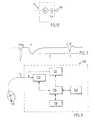
- Fig. 3shows the schematic drawing of a heart pacemaker 100 for tissue stimulation.
- the heart pacemaker 100comprises a stimulation pulse generator 120 that has its output side connected via a lead 11 to an electrode 10 applied in the ventricle of the heart for delivering stimulation pulses to the heart.
- the stimulation pulse generator 120can be activated to deliver a stimulation pulse via a control line, which is connected to a corresponding output of a control unit 130, e.g. a microprocessor.
- the stimulation pulse generated by the stimulation pulse generator 120may be anyone of the stimulation pulses known to the skilled person.
- the duration of the each stimulation pulse as well as the amplitude thereofare set by the control unit 130.
- the control unit 130has access to a memory 140 wherein a program that execute all functions of the heart pacemaker 100 via the control unit 130 is stored.
- the pacemaker 100comprises a telemetry unit 150 connected to the control unit 130 for programming and for monitoring the functions of the pacemaker 100 and of parameters acquired therewith on the basis of data exchange with an external programming and monitoring device (not shown).
- the pacemaker 100comprises a detector unit 110 which has an input side connected via the lead 11 to the electrode 10 for acquiring the electrical potential in the heart tissue.
- This arrangementis simple because only a single electrode 10 is required both for stimulating the heart and for acquiring the reaction thereof.
- the electrode according to the inventionmay be used only as stimulation electrode for stimulating tissue or a measuring electrode for acquiring the evoked response for e.g. operating in the VDD stimulating mode. In such cases either the stimulation generator 120 is programmed not to deliver stimulation pulses or the detector unit 110 not to register any evoked response (not shown).
- the control unit 130further comprises means for evaluating the electrical signals received by the detector 110 for making a diagnosis of the condition of the heart depending on e.g. the morphology of the electrical signal B or how the two electrical signals A and B relate to each other and/or to the stimulation pulse, and possibly for starting a therapy based on the made diagnosis.
- Fig. 4shows a schematic circuit diagram of a pacemaker in accordance with a first embodiment of the invention.
- the stimulation pulse generatorcomprises a charge pump 121, a capacitor C 1 , e.g. 1 ⁇ F, and a switch S1 which, when closed, charges the capacitor to a voltage of e.g. 20 V.
- the stimulation pulse generator 120rapidly transfers charge to the electrode 10, the thickness of the piezoelectric material 50 changes and pressure waves are emitted to the heart tissue. It is known that mechanical irritation of the endocardium can start a heart contraction, the mechanical stimulation may decrease the threshold for the electrical stimulation or may by itself initiate a heart contraction.
- the piezoelectric electrode 40, 50, 60functions as a capacitor as well, electrical current is transferred to the tissue when closing the switch S 2 .
- the capacitance C p of the piezoelectric materialpreferably is 10 to 100 nF, a relatively high voltage of about 5 to 25 volt is needed during a very short time of about 10 to 100 ⁇ s for reaching the stimulation threshold. This voltage may be generated inductively or capacitively and then be stored on C 1 .
- stimulation pulses with amplitudes and durations used with normal electrodesmay be used with the electrode 10 in accordance with the invention (0,6 - 5 volt at 0,5 ms).
- the diodemay be incorporated in the piezoelectric material 50 or consist of a detached component connected to the conductive materials 40, 60.
- the switch S 3is closed during for e.g. 5 to 15 ms so that the piezo electrode 45 is discharged when the next stimulation pulse arrives.
- a resistor with a very high resistance RLmay be connected across the diode, in order to avoid a build up of a charge on the piezo capacitance.
- the detector unit 110comprising a detector 111 and a charge amplifier 112 detects both electric signals A and B corresponding to the electrical and mechanical evoked response respectively registered by the piezo electrode 45.
- the stimulation pulse generator 120may generate a stimulation pulse which is chopped with a high frequency of e.g. 10 to 100 kHz.
- the chopped stimulation frequencymay be obtained by opening and closing the switch S 2 .
- the piezo sensorDue to the chopped stimulation pulse, the piezo sensor generates a series of pressure waves. Since the high frequency improves the electrical transmission through the piezo capacitor C p , there is no longer any need to have a diode integrated in the electrode as well as the capacitor C out , C out making it possible to avoid a net current which is not zero through the body.
- the piezoelectric electrode 10may be used together with a defibrillation electrode 300, either as two separated electrodes, i.e. two leads, or in combination on a single lead, whereby the piezoelectric electrode is placed at the tip of the lead and the intravascular defibrillation electrode 300 is placed behind the piezo electrode 10 as is shown in Fig. 6.
Landscapes
- Health & Medical Sciences (AREA)
- Heart & Thoracic Surgery (AREA)
- Vascular Medicine (AREA)
- Cardiology (AREA)
- Engineering & Computer Science (AREA)
- Biomedical Technology (AREA)
- Nuclear Medicine, Radiotherapy & Molecular Imaging (AREA)
- Radiology & Medical Imaging (AREA)
- Life Sciences & Earth Sciences (AREA)
- Animal Behavior & Ethology (AREA)
- General Health & Medical Sciences (AREA)
- Public Health (AREA)
- Veterinary Medicine (AREA)
- Electrotherapy Devices (AREA)
Abstract
Description
- Fig. 1A and 1B
- are schematic drawings of two embodiments of a tip electrode inaccordance with the invention, for both electrically and mechanicallystimulating tissue and detecting evoked response;
- Fig. 1C
- is a schematic drawing of an embodiment of a ring electrode in accordancewith the invention, for both electrically and mechanically stimulating tissueand detecting evoked response;
- Fig. 1D
- is a schematic drawing of an electrode lead in accordance with anembodiment of the invention;
- Fig. 1E
- is a schematic equivalent circuit of the piezoelectric electrode in accordancewith an embodiment of the invention;
- Fig. 2
- is a pulse diagram of the detector input signal generated by the electrode inaccordance with an embodiment of the invention and comprising thestimulation pulse, the electrical evoked response (A) and the mechanicalevoked response (B);
- Fig. 3
- is a schematic drawing of a heart pacemaker comprising an electrode inaccordance with the invention;
- Fig. 4
- is a schematic circuit diagram of a heart pacemaker in accordance with a firstembodiment of the invention;
- Fig. 5
- is a schematic circuit diagram of a heart pacemaker in accordance with asecond embodiment of the invention.
- Fig. 6
- is a schematic drawing of a single lead, whereby a piezoelectric electrode inaccordance with an embodiment of the invention is placed at the tip of thelead and an intravascular defibrillation electrode is placed behind the same.
Claims (24)
- An implantable electrode for an implantable stimulation device comprising apiezoelectric electrode (40,50,60) for electrically and mechanically transferringstimulation energy to tissue.
- An implantable electrode for an implantable stimulation device comprising apiezoelectric electrode (40,50,60) for electrically and mechanically receivingelectrical and mechanical evoked response of the tissue to which stimulation energyhas been transferred.
- An implantable electrode for an implantable stimulation device comprising apiezoelectric electrode (40,50,60) for electrically and mechanically transferringstimulation energy to tissue and electrically and mechanically receiving electricaland mechanical evoked response of the tissue to which stimulation energy has beentransferred.
- An implantable electrode as claimed in any one of claims 1 to 3, characterised inthat the piezoelectric electrode (40,50,60) comprises a metal core 40 covered by apiezoelectric material (50) which is covered by a conductive layer (60).
- An implantable electrode as claimed in claim 4, characterised in that thecapacitance (Cp) of the piezoelectric material (50) is 10 to 100 nF.
- An implantable electrode as claimed in claims 4 or 5, characterised in that theconductive layer (60) is a high double-layer capacitance.
- An implantable electrode as claimed in any one of claims 4 to 6, characterised inthat the conductive layer (60) is biocompatible.
- An implantable electrode as claimed in any one of claims 4 to 7, characterised inthat the conductive layer (60) is porous.
- An implantable electrode as claimed in any one of claims 1 to 8, characterised inthat the piezoelectric electrode (40,50,60) is a tip electrode.
- An implantable electrode as claimed in claim 9, characterised in that thepiezoelectric electrode (40,50,60) is hemispherical.
- An implantable electrode as claimed in claim 9, characterised in that the distalend of the piezoelectric electrode (40,50,60) is planar.
- An implantable electrode as claimed in claim 11 when depending on any one ofclaims 4 to 7, characterised in that the conductive layer (60) partly covers thepiezoelectric material (50) and a biocompatible material (70) covers the remainingpart thereof.
- An implantable electrode as claimed in any one of claims 1 to 8, characterised inthat the piezoelectric electrode (40,50,60) is a ring electrode.
- An implantable electrode as claimed in claim 13, characterised in that thepiezoelectric electrode (40,50,60) is coaxial.
- An implantable electrode as claimed in any one of claims 1 to 14, characterisedin that the stimulating pulse generator (120) generates a chopped stimulation pulse.
- An amplantable electrode as claimed in claim 15, characterised in that thestimulation pulse is chopped with a frequency between 10 to 100 kHz.
- An implantable electrode as claimed in any one of claims 1 to 16, characterisedby further comprising conductor means (20,40) for conducting the stimulation energy to the piezoelectric electrode (50.60) and for conducting the electrical signalsgenerated by the piezoelectric electrode (50,60) and corresponding to the electricaland mechanical evoked response of the stimulated tissue.
- An electrode lead connectable to an implantable stimulation device, whereinsaid elektrode lead comprises an implantable electrode (10) as claimed in any one ofclaims 1 to 17 and further comprises a conductor (13) for delivering stimulationenergy to the piezoelectric electrode (40,50,60) ) and/or for conducting signals fromthe piezoelectric electrode (40,50,60) corresponding to the electrical and mechanicalevoked response of the stimulated tissue.
- An implantable stimulation device for stimulating tissue comprising animplantable electrode (10) as claimed in any one of claims 1 to 17, a stimulationpulse generator (120) for delivering stimulation energy to said implantable electrode(10) and detector means (110) for receiving signals from said implantable electrode(10) corresponding to the electrical and mechanical evoked response of thestimulated tissue.
- An implantable stimulation device as claimed in claim 19, characterised byfurther comprising control unit (130) for processing the signals received by thedetector means (110).
- An implantable stimulation device as claimed in any one of claims 19 or 20,characterised in that the control unit (130) comprises detecting means for detectingfusion beats, said detecting means determining if the electrical signal (B)corresponding to the mechanical evoked response registered by the electrode (10),arrives before a predetermined time window (C).
- An implantable stimulation device as claimed in any one of claims 19 or 20,characterised in that the control unit (130) comprises analysing means for analysingthe heart contractility, said analysing means determining the morphology of the electrical signal (B) corresponding to the mechanical evoked response registered bythe electrode (10).
- An implantable stimulation device as claimed in any one of claims 19 or 20,characterised by comprising pacing means for dual-chamber pacing having an A-Vtimer and in that the control unit (130) comprises means for providing a stable heartfunction, said providing means starting the A-V timer after the detection of theelectrical signal (B) corresponding the mechanical evoked response.
- An implantable stimulation device as claimed in any one of claims 19 or 20,characterised in that the control unit (130) comprises means for avoidingelectromechanical dissociation, said avoiding means determining if the electrode(10) registers both an electrical and a mechanical evoked response of the tissue aftera stimulation.
Applications Claiming Priority (3)
| Application Number | Priority Date | Filing Date | Title |
|---|---|---|---|
| CH9603066 | 1996-08-23 | ||
| CH96030/66 | 1996-08-23 | ||
| SE9603066ASE9603066D0 (en) | 1996-08-23 | 1996-08-23 | Electrode for tissue stimulation |
Publications (2)
| Publication Number | Publication Date |
|---|---|
| EP0824935A2true EP0824935A2 (en) | 1998-02-25 |
| EP0824935A3 EP0824935A3 (en) | 1999-12-01 |
Family
ID=20403638
Family Applications (1)
| Application Number | Title | Priority Date | Filing Date |
|---|---|---|---|
| EP97850122AWithdrawnEP0824935A3 (en) | 1996-08-23 | 1997-08-18 | Electrode for tissue stimulation |
Country Status (4)
| Country | Link |
|---|---|
| US (1) | US5935158A (en) |
| EP (1) | EP0824935A3 (en) |
| JP (1) | JPH1080495A (en) |
| SE (1) | SE9603066D0 (en) |
Cited By (5)
| Publication number | Priority date | Publication date | Assignee | Title |
|---|---|---|---|---|
| WO1999042169A1 (en)* | 1998-02-23 | 1999-08-26 | Pacesetter Ab | Implantable biocompatible electrode for both electrically and mechanically stimulating the tissue |
| WO1999053972A1 (en)* | 1998-04-22 | 1999-10-28 | St. Jude Medical Ab | Implant |
| WO1999054266A1 (en)* | 1998-04-22 | 1999-10-28 | St. Jude Medical Ab | Biocompatible material for implants |
| US7305270B1 (en) | 2005-04-21 | 2007-12-04 | Pacesetter, Inc. | Cardiac pacing/sensing lead providing far-field signal rejection |
| US7569020B2 (en) | 2006-06-19 | 2009-08-04 | St. Jude Medical Ab | Method for extracting timing parameters using a cardio-mechanical sensor |
Families Citing this family (33)
| Publication number | Priority date | Publication date | Assignee | Title |
|---|---|---|---|---|
| US6298267B1 (en) | 1999-04-30 | 2001-10-02 | Intermedics Inc. | Method and apparatus for treatment of cardiac electromechanical dissociation |
| US6263241B1 (en) | 1999-04-30 | 2001-07-17 | Intermedics, Inc. | Method and apparatus for treatment of cardiac electromechanical dissociation |
| US7483743B2 (en)* | 2000-01-11 | 2009-01-27 | Cedars-Sinai Medical Center | System for detecting, diagnosing, and treating cardiovascular disease |
| US8298150B2 (en) | 2000-01-11 | 2012-10-30 | Cedars-Sinai Medical Center | Hemodynamic waveform-based diagnosis and treatment |
| SE0003341D0 (en) | 2000-09-18 | 2000-09-18 | St Jude Medical | A coating method |
| US6430448B1 (en)* | 2000-11-07 | 2002-08-06 | Pacesetter, Inc. | Stimulating electrode having low polarization and method of making same |
| US6430447B1 (en)* | 2000-11-07 | 2002-08-06 | Pacesetter, Inc. | Stimulating electrode having low polarization and method of making same |
| WO2002063650A1 (en)* | 2001-02-06 | 2002-08-15 | Corning Incorporated | Plasma fusion splicer electrode |
| US6687545B1 (en) | 2001-10-23 | 2004-02-03 | Pacesetter, Inc. | Cardiac stimulation system and method for performing automatic capture verification during bipolar stimulation |
| IL148299A (en)* | 2002-02-21 | 2014-04-30 | Technion Res & Dev Foundation | Ultrasound cardiac stimulator |
| EP1428551A1 (en)* | 2002-12-13 | 2004-06-16 | W.C. Heraeus GmbH & Co. KG | Stimulation electrode and manufacturing and use thereof |
| US7123969B1 (en) | 2003-05-21 | 2006-10-17 | Pacesetter, Inc. | Lead having one or more low polarization electrodes |
| WO2004112895A1 (en) | 2003-06-17 | 2004-12-29 | Ebr Systems, Inc. | Vibrational pacing therapy device |
| US7006864B2 (en)* | 2003-06-17 | 2006-02-28 | Ebr Systems, Inc. | Methods and systems for vibrational treatment of cardiac arrhythmias |
| US7184830B2 (en)* | 2003-08-18 | 2007-02-27 | Ebr Systems, Inc. | Methods and systems for treating arrhythmias using a combination of vibrational and electrical energy |
| US7050849B2 (en)* | 2003-11-06 | 2006-05-23 | Ebr Systems, Inc. | Vibrational therapy device used for resynchronization pacing in a treatment for heart failure |
| EP1711222A4 (en)* | 2003-12-19 | 2011-02-09 | Savacor Inc | Digital electrode for cardiac rhythm management |
| US7610092B2 (en) | 2004-12-21 | 2009-10-27 | Ebr Systems, Inc. | Leadless tissue stimulation systems and methods |
| US7765001B2 (en)* | 2005-08-31 | 2010-07-27 | Ebr Systems, Inc. | Methods and systems for heart failure prevention and treatments using ultrasound and leadless implantable devices |
| JP2008518706A (en)* | 2004-11-04 | 2008-06-05 | エル・アンド・ピー・100・リミテッド | Medical device |
| US7558631B2 (en)* | 2004-12-21 | 2009-07-07 | Ebr Systems, Inc. | Leadless tissue stimulation systems and methods |
| JP5153343B2 (en)* | 2004-12-21 | 2013-02-27 | イービーアール システムズ, インコーポレイテッド | Implantable transducer device |
| US20060149324A1 (en)* | 2004-12-30 | 2006-07-06 | Brian Mann | Cardiac rhythm management with interchangeable components |
| US20060149330A1 (en)* | 2004-12-30 | 2006-07-06 | Brian Mann | Digitally controlled cardiac rhythm management |
| US7590445B1 (en)* | 2005-02-01 | 2009-09-15 | Pacesetter, Inc. | Indirect mechanical medical therapy system |
| US7702392B2 (en) | 2005-09-12 | 2010-04-20 | Ebr Systems, Inc. | Methods and apparatus for determining cardiac stimulation sites using hemodynamic data |
| US7756577B1 (en) | 2006-04-21 | 2010-07-13 | Pacesetter, Inc. | Multi-modal medical therapy system |
| US8718773B2 (en) | 2007-05-23 | 2014-05-06 | Ebr Systems, Inc. | Optimizing energy transmission in a leadless tissue stimulation system |
| US7953493B2 (en) | 2007-12-27 | 2011-05-31 | Ebr Systems, Inc. | Optimizing size of implantable medical devices by isolating the power source |
| WO2009120636A1 (en)* | 2008-03-25 | 2009-10-01 | Ebr Systems, Inc. | Temporary electrode connection for wireless pacing systems |
| US20100016911A1 (en) | 2008-07-16 | 2010-01-21 | Ebr Systems, Inc. | Local Lead To Improve Energy Efficiency In Implantable Wireless Acoustic Stimulators |
| WO2022040235A1 (en) | 2020-08-17 | 2022-02-24 | Ebr Systems, Inc. | Implantable stimulation assemblies having tissue engagement mechanisms, and associated systems and methods |
| US12350497B2 (en) | 2022-02-10 | 2025-07-08 | Ebr Systems, Inc. | Tissue stimulation systems and methods, such as for pacing cardiac tissue |
Citations (3)
| Publication number | Priority date | Publication date | Assignee | Title |
|---|---|---|---|---|
| US5304208A (en) | 1991-05-21 | 1994-04-19 | Sorin Biomedica S.P.A. | Cardiostimulator device of the rate-responsive type |
| US5433731A (en) | 1993-03-29 | 1995-07-18 | Pacesetter Ab | Mechanical defibrillator and method for defibrillating a heart |
| US5476499A (en) | 1993-12-03 | 1995-12-19 | Pacesetter Ab | Medical electrode lead with atrial electrode at the distal and ventricular electrode between the distal and proximal ends |
Family Cites Families (12)
| Publication number | Priority date | Publication date | Assignee | Title |
|---|---|---|---|---|
| US4485813A (en)* | 1981-11-19 | 1984-12-04 | Medtronic, Inc. | Implantable dynamic pressure transducer system |
| US4798206A (en)* | 1986-10-28 | 1989-01-17 | Telectronics N.V. | Implanted medical system including a self-powered sensing system |
| US5271392A (en)* | 1990-08-24 | 1993-12-21 | Siemens-Elema Ab | Method and apparatus for administering cardiac electrotherapy dependent on mechanical and electrical cardiac activity |
| EP0473070B1 (en)* | 1990-08-24 | 1995-11-29 | Bozidar Ferek-Petric | Cardiac pacing systems with tensiometry |
| US5109842A (en)* | 1990-09-24 | 1992-05-05 | Siemens Pacesetter, Inc. | Implantable tachyarrhythmia control system having a patch electrode with an integrated cardiac activity system |
| US5324326A (en)* | 1991-11-25 | 1994-06-28 | Telectronics Pacing Systems, Inc. | Pressure sensing pacing lead |
| US5207230A (en)* | 1992-02-06 | 1993-05-04 | Bowers David L | Spiral sensor |
| US5397344A (en)* | 1992-12-22 | 1995-03-14 | Schering Aktiengesellschaft | Methods of and apparatus for measuring uterine electrical and mechanical activity |
| SE9302357D0 (en)* | 1993-07-07 | 1993-07-07 | Siemens-Elema Ab | PRESSURE AND HEARING MOVEMENT SENSOR WITH HEART STIMULATORS |
| US5423883A (en)* | 1993-07-14 | 1995-06-13 | Pacesetter, Inc. | Implantable myocardial stimulation lead with sensors thereon |
| US5628777A (en)* | 1993-07-14 | 1997-05-13 | Pacesetter, Inc. | Implantable leads incorporating cardiac wall acceleration sensors and method of fabrication |
| US5800536A (en)* | 1997-05-09 | 1998-09-01 | The United States Of America As Represented By The Secretary Of The Navy | Passive piezoelectric prosthesis for the inner ear |
- 1996
- 1996-08-23SESE9603066Apatent/SE9603066D0/enunknown
- 1997
- 1997-08-18EPEP97850122Apatent/EP0824935A3/ennot_activeWithdrawn
- 1997-08-21USUS08/915,756patent/US5935158A/ennot_activeExpired - Fee Related
- 1997-08-25JPJP9228007Apatent/JPH1080495A/enactivePending
Patent Citations (3)
| Publication number | Priority date | Publication date | Assignee | Title |
|---|---|---|---|---|
| US5304208A (en) | 1991-05-21 | 1994-04-19 | Sorin Biomedica S.P.A. | Cardiostimulator device of the rate-responsive type |
| US5433731A (en) | 1993-03-29 | 1995-07-18 | Pacesetter Ab | Mechanical defibrillator and method for defibrillating a heart |
| US5476499A (en) | 1993-12-03 | 1995-12-19 | Pacesetter Ab | Medical electrode lead with atrial electrode at the distal and ventricular electrode between the distal and proximal ends |
Cited By (7)
| Publication number | Priority date | Publication date | Assignee | Title |
|---|---|---|---|---|
| WO1999042169A1 (en)* | 1998-02-23 | 1999-08-26 | Pacesetter Ab | Implantable biocompatible electrode for both electrically and mechanically stimulating the tissue |
| WO1999053972A1 (en)* | 1998-04-22 | 1999-10-28 | St. Jude Medical Ab | Implant |
| WO1999054266A1 (en)* | 1998-04-22 | 1999-10-28 | St. Jude Medical Ab | Biocompatible material for implants |
| US6526984B1 (en) | 1998-04-22 | 2003-03-04 | St. Jude Medical Ab | Biocompatible material for implants |
| US6571130B1 (en) | 1998-04-22 | 2003-05-27 | St. Jude Medical Ab | Medical implant with piezoelectric material in contact with body tissue |
| US7305270B1 (en) | 2005-04-21 | 2007-12-04 | Pacesetter, Inc. | Cardiac pacing/sensing lead providing far-field signal rejection |
| US7569020B2 (en) | 2006-06-19 | 2009-08-04 | St. Jude Medical Ab | Method for extracting timing parameters using a cardio-mechanical sensor |
Also Published As
| Publication number | Publication date |
|---|---|
| SE9603066D0 (en) | 1996-08-23 |
| JPH1080495A (en) | 1998-03-31 |
| US5935158A (en) | 1999-08-10 |
| EP0824935A3 (en) | 1999-12-01 |
Similar Documents
| Publication | Publication Date | Title |
|---|---|---|
| US6529777B1 (en) | Electrode for tissue stimulation | |
| US5935158A (en) | Electrode lead and device for tissue stimulation and/or detection of tissue response | |
| US4895152A (en) | System for cardiac pacing | |
| US6334071B1 (en) | Minute volume pacemakers that require only a single distal electrode | |
| US7873415B2 (en) | Cardiac rhythm management system and method | |
| US7203542B2 (en) | Implantable biventricular cardiac stimulator with capture monitoring by IECG analysis | |
| US5411529A (en) | Waveform discriminator for cardiac stimulation devices | |
| EP0236562A1 (en) | Apparatus for cardiac pacing with detection of cardiac evoked potentials | |
| US9254392B2 (en) | Anodal capture detection | |
| WO2003090861A1 (en) | Capture management in multi-site pacing | |
| JP2002500938A (en) | Tachycardia induction system using near-field T-wave detection | |
| WO2006036667A1 (en) | Implantable medical lead | |
| US7734346B2 (en) | Identification of premature atrial contractions that trigger arrhythmia | |
| WO2002045797A2 (en) | Distinguishing valid and invalid cardiac senses | |
| US11013926B2 (en) | Active implantable medical device with dynamic optimization of stimulation pulse energy | |
| EP1882493A2 (en) | Cardiac pacemaker | |
| EP1620176B1 (en) | Bi-ventricular and single-ventricle pacing | |
| US20100087886A1 (en) | Method and device for processing cardiac signals |
Legal Events
| Date | Code | Title | Description |
|---|---|---|---|
| PUAI | Public reference made under article 153(3) epc to a published international application that has entered the european phase | Free format text:ORIGINAL CODE: 0009012 | |
| AK | Designated contracting states | Kind code of ref document:A2 Designated state(s):DE ES FR GB IT | |
| PUAL | Search report despatched | Free format text:ORIGINAL CODE: 0009013 | |
| AK | Designated contracting states | Kind code of ref document:A3 Designated state(s):AT BE CH DE DK ES FI FR GB GR IE IT LI LU MC NL PT SE | |
| RIC1 | Information provided on ipc code assigned before grant | Free format text:6A 61N 1/05 A, 6A 61N 1/37 B | |
| 17P | Request for examination filed | Effective date:20000216 | |
| AKX | Designation fees paid | Free format text:DE ES FR GB IT | |
| RAP1 | Party data changed (applicant data changed or rights of an application transferred) | Owner name:ST. JUDE MEDICAL AB | |
| 17Q | First examination report despatched | Effective date:20040803 | |
| GRAP | Despatch of communication of intention to grant a patent | Free format text:ORIGINAL CODE: EPIDOSNIGR1 | |
| GRAJ | Information related to disapproval of communication of intention to grant by the applicant or resumption of examination proceedings by the epo deleted | Free format text:ORIGINAL CODE: EPIDOSDIGR1 | |
| APBK | Appeal reference recorded | Free format text:ORIGINAL CODE: EPIDOSNREFNE | |
| APBN | Date of receipt of notice of appeal recorded | Free format text:ORIGINAL CODE: EPIDOSNNOA2E | |
| APBR | Date of receipt of statement of grounds of appeal recorded | Free format text:ORIGINAL CODE: EPIDOSNNOA3E | |
| APAV | Appeal reference deleted | Free format text:ORIGINAL CODE: EPIDOSDREFNE | |
| APBT | Appeal procedure closed | Free format text:ORIGINAL CODE: EPIDOSNNOA9E | |
| STAA | Information on the status of an ep patent application or granted ep patent | Free format text:STATUS: THE APPLICATION HAS BEEN WITHDRAWN | |
| 18W | Application withdrawn | Effective date:20120620 |