EP0824923A1 - Cartrigde with temporarily lockable cap for an injection device - Google Patents
Cartrigde with temporarily lockable cap for an injection deviceDownload PDFInfo
- Publication number
- EP0824923A1 EP0824923A1EP97114272AEP97114272AEP0824923A1EP 0824923 A1EP0824923 A1EP 0824923A1EP 97114272 AEP97114272 AEP 97114272AEP 97114272 AEP97114272 AEP 97114272AEP 0824923 A1EP0824923 A1EP 0824923A1
- Authority
- EP
- European Patent Office
- Prior art keywords
- sleeve
- assembly
- cap
- locking member
- finger
- Prior art date
- Legal status (The legal status is an assumption and is not a legal conclusion. Google has not performed a legal analysis and makes no representation as to the accuracy of the status listed.)
- Granted
Links
- 238000002347injectionMethods0.000titleclaimsdescription23
- 239000007924injectionSubstances0.000titleclaimsdescription23
- 239000012530fluidSubstances0.000claimsdescription3
- 238000010304firingMethods0.000abstractdescription10
- 239000000463materialSubstances0.000abstractdescription7
- 238000006073displacement reactionMethods0.000abstractdescription4
- 238000000034methodMethods0.000description9
- 239000003814drugSubstances0.000description6
- 210000003491skinAnatomy0.000description6
- 229940079593drugDrugs0.000description5
- 238000003780insertionMethods0.000description4
- 230000037431insertionEffects0.000description4
- 230000007246mechanismEffects0.000description4
- 230000000994depressogenic effectEffects0.000description3
- 210000002615epidermisAnatomy0.000description3
- 238000013459approachMethods0.000description2
- 230000006835compressionEffects0.000description2
- 238000007906compressionMethods0.000description2
- 230000008878couplingEffects0.000description2
- 238000010168coupling processMethods0.000description2
- 238000005859coupling reactionMethods0.000description2
- NOESYZHRGYRDHS-UHFFFAOYSA-NinsulinChemical compoundN1C(=O)C(NC(=O)C(CCC(N)=O)NC(=O)C(CCC(O)=O)NC(=O)C(C(C)C)NC(=O)C(NC(=O)CN)C(C)CC)CSSCC(C(NC(CO)C(=O)NC(CC(C)C)C(=O)NC(CC=2C=CC(O)=CC=2)C(=O)NC(CCC(N)=O)C(=O)NC(CC(C)C)C(=O)NC(CCC(O)=O)C(=O)NC(CC(N)=O)C(=O)NC(CC=2C=CC(O)=CC=2)C(=O)NC(CSSCC(NC(=O)C(C(C)C)NC(=O)C(CC(C)C)NC(=O)C(CC=2C=CC(O)=CC=2)NC(=O)C(CC(C)C)NC(=O)C(C)NC(=O)C(CCC(O)=O)NC(=O)C(C(C)C)NC(=O)C(CC(C)C)NC(=O)C(CC=2NC=NC=2)NC(=O)C(CO)NC(=O)CNC2=O)C(=O)NCC(=O)NC(CCC(O)=O)C(=O)NC(CCCNC(N)=N)C(=O)NCC(=O)NC(CC=3C=CC=CC=3)C(=O)NC(CC=3C=CC=CC=3)C(=O)NC(CC=3C=CC(O)=CC=3)C(=O)NC(C(C)O)C(=O)N3C(CCC3)C(=O)NC(CCCCN)C(=O)NC(C)C(O)=O)C(=O)NC(CC(N)=O)C(O)=O)=O)NC(=O)C(C(C)CC)NC(=O)C(CO)NC(=O)C(C(C)O)NC(=O)C1CSSCC2NC(=O)C(CC(C)C)NC(=O)C(NC(=O)C(CCC(N)=O)NC(=O)C(CC(N)=O)NC(=O)C(NC(=O)C(N)CC=1C=CC=CC=1)C(C)C)CC1=CN=CN1NOESYZHRGYRDHS-UHFFFAOYSA-N0.000description2
- 238000012986modificationMethods0.000description2
- 230000004048modificationEffects0.000description2
- 230000037368penetrate the skinEffects0.000description2
- 230000002028prematureEffects0.000description2
- 230000008569processEffects0.000description2
- 206010020751HypersensitivityDiseases0.000description1
- 102000004877InsulinHuman genes0.000description1
- 108090001061InsulinProteins0.000description1
- 208000026935allergic diseaseDiseases0.000description1
- 230000007815allergyEffects0.000description1
- 239000003708ampulSubstances0.000description1
- 230000001387anti-histamineEffects0.000description1
- 229940125715antihistaminic agentDrugs0.000description1
- 239000000739antihistaminic agentSubstances0.000description1
- 230000000712assemblyEffects0.000description1
- 238000000429assemblyMethods0.000description1
- 238000009434installationMethods0.000description1
- 229940125396insulinDrugs0.000description1
- 230000014759maintenance of locationEffects0.000description1
- 230000000717retained effectEffects0.000description1
- 238000000926separation methodMethods0.000description1
- 210000001519tissueAnatomy0.000description1
- 230000000007visual effectEffects0.000description1
- 238000003466weldingMethods0.000description1
Images


Classifications
- A—HUMAN NECESSITIES
- A61—MEDICAL OR VETERINARY SCIENCE; HYGIENE
- A61M—DEVICES FOR INTRODUCING MEDIA INTO, OR ONTO, THE BODY; DEVICES FOR TRANSDUCING BODY MEDIA OR FOR TAKING MEDIA FROM THE BODY; DEVICES FOR PRODUCING OR ENDING SLEEP OR STUPOR
- A61M5/00—Devices for bringing media into the body in a subcutaneous, intra-vascular or intramuscular way; Accessories therefor, e.g. filling or cleaning devices, arm-rests
- A61M5/178—Syringes
- A61M5/20—Automatic syringes, e.g. with automatically actuated piston rod, with automatic needle injection, filling automatically
- A61M5/2033—Spring-loaded one-shot injectors with or without automatic needle insertion
- A—HUMAN NECESSITIES
- A61—MEDICAL OR VETERINARY SCIENCE; HYGIENE
- A61M—DEVICES FOR INTRODUCING MEDIA INTO, OR ONTO, THE BODY; DEVICES FOR TRANSDUCING BODY MEDIA OR FOR TAKING MEDIA FROM THE BODY; DEVICES FOR PRODUCING OR ENDING SLEEP OR STUPOR
- A61M5/00—Devices for bringing media into the body in a subcutaneous, intra-vascular or intramuscular way; Accessories therefor, e.g. filling or cleaning devices, arm-rests
- A61M5/178—Syringes
- A61M5/31—Details
- A61M5/32—Needles; Details of needles pertaining to their connection with syringe or hub; Accessories for bringing the needle into, or holding the needle on, the body; Devices for protection of needles
- A61M5/3202—Devices for protection of the needle before use, e.g. caps
- A—HUMAN NECESSITIES
- A61—MEDICAL OR VETERINARY SCIENCE; HYGIENE
- A61M—DEVICES FOR INTRODUCING MEDIA INTO, OR ONTO, THE BODY; DEVICES FOR TRANSDUCING BODY MEDIA OR FOR TAKING MEDIA FROM THE BODY; DEVICES FOR PRODUCING OR ENDING SLEEP OR STUPOR
- A61M5/00—Devices for bringing media into the body in a subcutaneous, intra-vascular or intramuscular way; Accessories therefor, e.g. filling or cleaning devices, arm-rests
- A61M5/178—Syringes
- A61M5/20—Automatic syringes, e.g. with automatically actuated piston rod, with automatic needle injection, filling automatically
- A61M2005/206—With automatic needle insertion
- A—HUMAN NECESSITIES
- A61—MEDICAL OR VETERINARY SCIENCE; HYGIENE
- A61M—DEVICES FOR INTRODUCING MEDIA INTO, OR ONTO, THE BODY; DEVICES FOR TRANSDUCING BODY MEDIA OR FOR TAKING MEDIA FROM THE BODY; DEVICES FOR PRODUCING OR ENDING SLEEP OR STUPOR
- A61M5/00—Devices for bringing media into the body in a subcutaneous, intra-vascular or intramuscular way; Accessories therefor, e.g. filling or cleaning devices, arm-rests
- A61M5/178—Syringes
- A61M5/20—Automatic syringes, e.g. with automatically actuated piston rod, with automatic needle injection, filling automatically
- A61M2005/2073—Automatic syringes, e.g. with automatically actuated piston rod, with automatic needle injection, filling automatically preventing premature release, e.g. by making use of a safety lock
- A61M2005/208—Release is possible only when device is pushed against the skin, e.g. using a trigger which is blocked or inactive when the device is not pushed against the skin
- A—HUMAN NECESSITIES
- A61—MEDICAL OR VETERINARY SCIENCE; HYGIENE
- A61M—DEVICES FOR INTRODUCING MEDIA INTO, OR ONTO, THE BODY; DEVICES FOR TRANSDUCING BODY MEDIA OR FOR TAKING MEDIA FROM THE BODY; DEVICES FOR PRODUCING OR ENDING SLEEP OR STUPOR
- A61M5/00—Devices for bringing media into the body in a subcutaneous, intra-vascular or intramuscular way; Accessories therefor, e.g. filling or cleaning devices, arm-rests
- A61M5/178—Syringes
- A61M5/31—Details
- A61M5/32—Needles; Details of needles pertaining to their connection with syringe or hub; Accessories for bringing the needle into, or holding the needle on, the body; Devices for protection of needles
- A61M5/3202—Devices for protection of the needle before use, e.g. caps
- A61M5/3204—Needle cap remover, i.e. devices to dislodge protection cover from needle or needle hub, e.g. deshielding devices
- A—HUMAN NECESSITIES
- A61—MEDICAL OR VETERINARY SCIENCE; HYGIENE
- A61M—DEVICES FOR INTRODUCING MEDIA INTO, OR ONTO, THE BODY; DEVICES FOR TRANSDUCING BODY MEDIA OR FOR TAKING MEDIA FROM THE BODY; DEVICES FOR PRODUCING OR ENDING SLEEP OR STUPOR
- A61M5/00—Devices for bringing media into the body in a subcutaneous, intra-vascular or intramuscular way; Accessories therefor, e.g. filling or cleaning devices, arm-rests
- A61M5/178—Syringes
- A61M5/31—Details
- A61M5/32—Needles; Details of needles pertaining to their connection with syringe or hub; Accessories for bringing the needle into, or holding the needle on, the body; Devices for protection of needles
- A61M5/3205—Apparatus for removing or disposing of used needles or syringes, e.g. containers; Means for protection against accidental injuries from used needles
- A61M5/321—Means for protection against accidental injuries by used needles
- A61M5/3243—Means for protection against accidental injuries by used needles being axially-extensible, e.g. protective sleeves coaxially slidable on the syringe barrel
- A61M5/326—Fully automatic sleeve extension, i.e. in which triggering of the sleeve does not require a deliberate action by the user
Definitions
- the field of the inventionrelates to injection devices for automatically dispensing premeasured quantities of material, and disposable assemblies therefor.
- Injection devicessuch as syringes are widely used in the medical and veterinary fields. They are ordinarily employed by trained personnel who are capable of selecting the appropriate medication and administering the required dosage.
- U.S. Patent No. 2,752,918discloses one type of automatically operated injection device. Upon firing an actuating mechanism of this device, a needle is caused to penetrate the skin, medicament is injected through the bore of the needle, and the needle is retracted.
- the deviceincludes a first coil spring for causing the needle to be projected beyond a nose piece and a second coil spring which is compressed during this procedure. The second spring, upon release of a clutch mechanism, then automatically urges an ampule and stem rearwardly, causing retraction of the needle.
- U.S. Patent No. 5,137,516discloses another type of automatically operated injection device.
- the userfirst presses the device against the skin in order to move an internal shaft and sleeve assembly.
- An actuating buttonis then depressed, causing a button arm to spread the arms of a retention clip.
- the separation of these armsreleases the head of the pusher rod, which is then moved forwardly under the force of a main coil spring.
- the pusher rodfirst moves the entire syringe against the force of a syringe spring.
- the syringe plungeris depressed by the pusher rod, causing the syringe to empty.
- the main spring of the patented devicemay be recocked upon reloading of a new syringe assembly. Such reloading is accomplished by a force applied by the syringe piston directly upon the pusher rod of the device.
- U.S. Patent No. 5,478,316discloses a device including a drive assembly and a disposable syringe assembly coupled thereto.
- the drive assemblyincludes a constant force spring which urges the syringe assembly in such a manner that the syringe needle is first caused to enter a patient s skin. This step is followed by the injection of fluid through the needle into the patient.
- the syringe assembly of the patented deviceincludes, inter alia , a sleeve and a cap.
- the capis mounted to one end of the sleeve, and protects the needle prior to use of the device. As the cap does not rotate with respect to the sleeve, it may be grasped by the user during the process of coupling the syringe assembly to the drive assembly.
- the drive assembly of the patented deviceincludes a housing which is coupled to a collar.
- the collarincludes a slot which, during installation of the syringe assembly, is aligned with a longitudinal rib extending radially outwardly from the sleeve. This sleeve can be pushed into the housing of the drive assembly when so aligned, thereby loading the spring. The syringe assembly is then rotated, causing engagement of the push button of the drive assembly with a projection at one end of the sleeve.
- the inventionconcerns an injection device, and a sleeve and syringe assembly therefor, which are safe to use, reliable, and which facilitate the self-administration of medicines and other materials.
- an injection devicewhich includes a housing, a syringe assembly slidably mounted to the housing, and a spring for moving the syringe assembly with respect to the housing and towards the skin of a patient.
- the deviceincludes a sleeve which is coupled to the housing.
- the syringe assemblyis positioned at least partially within the sleeve.
- a capis removably mounted to the sleeve.
- First and second locking members on the cap and sleeve, respectively,allow the cap to be temporarily locked to the sleeve.
- a lock release assemblyallows the disengagement of the cap and sleeve when the device is ready for firing.
- a disposable assemblywhich includes a sleeve and a syringe assembly slidably positioned within the sleeve.
- a capis removably mounted to one end of the sleeve.
- First and second locking members on the cap and sleeve, respectively,allow the cap to be temporarily locked together.
- the sleeveincludes a lock release member which, when actuated, allows the cap to be removed from the sleeve.
- the second locking member and lock release memberare both preferably positioned on a deflectable finger running parallel to the longitudinal axis of the sleeve. Deflection of the finger causes disengagement of the first and second locking members, thereby allowing the cap to be removed from the sleeve.
- the improvements as described aboveprevent the cap from being removed prior to movement of the sleeve/syringe assembly into the firing position within the drive assembly housing.
- the locking of the cap to the sleevealso facilitates safe removal of the sleeve once an injection has been made.
- An injection device 10is provided which is particularly adapted for the self-administration of medicines and other materials.
- the deviceis similar in structure and operation to that described in U.S. Patent No. 5,478,316, which is incorporated by reference herein.
- the deviceincludes a drive assembly including an elongate housing 12 which may be easily handled by a user.
- One end of the housingis closed, while the opposite end is mounted to a collar 14.
- the collaris permanently mounted to the housing 12, and may be considered a part of the housing.
- a cap 16is mounted to one end of a sleeve 28 in adjoining relation to the collar.
- the capis not rotatable upon the sleeve, and is employed in conjunction with the collar for mounting a syringe assembly to the drive assembly.
- a plurality of elongate ribs 18 on the exterior surface of the capare used during the mounting procedure, which is described in detail below.
- a syringe assembly 20is provided in accordance with the preferred embodiment of the invention.
- a plug 24is mounted to one end of the syringe assembly, and a needle assembly 26 is mounted to the opposite end thereof.
- the sleeve 28encloses the syringe assembly.
- the syringe assemblyincludes a cartridge 30 or barrel and a piston 32 slidably positioned within the cartridge.
- the cap 16is removably mounted to one end of the sleeve.
- An annular slot 34is defined by a pair of concentric walls of the cap.
- the end portion of the sleeve 28is positioned within the annular slot.
- a rubber shield 36is positioned within the cap, and protects the needle 38 of the syringe assembly.
- the shieldis frictionally retained by the cap, and is removable with the cap when the device is to be employed. Rotation of the cap causes rotation of the syringe assembly 20 and sleeve 28 with respect to the drive assembly when a new syringe and sleeve assembly is secured thereto.
- a coil spring 40is provided for resiliently urging the sleeve 28 with respect to the cartridge 30.
- the cartridgeincludes a flange 42 which abuts against one end of the spring. The other end of the spring engages a radially inwardly extending wall of the sleeve. A portion 44 of the sleeve extends behind the plug 24, thereby preventing the sleeve and plug from being disconnected from the syringe assembly.
- the spring 40causes the sleeve to extend over the needle in its rest position, as shown in Fig. 3.
- the drive assembly of the deviceis designed for repeated use.
- the drive assembly housing 12is comprised of two sections 12A, 12B secured to each other by ultra-sonic welding or other suitable procedure.
- An elongate drive rod 46is positioned within the housing. Guide rails 47 integral with the housing 12 maintain the orientation of the rod.
- the rod 46includes an integral saddle 48 at one end thereof. The opposite end of the rod is smaller in dimension such that it fits within the plug 24 and cartridge 30.
- a ramp 50is defined on one side of the rod near the saddle end thereof.
- the opposite side of the rodincludes a plurality of notches 52.
- An elongate groove 54extends from the end of the rod within the cartridge for a distance corresponding to at least the maximum length of travel of the piston 32 within the cartridge 30.
- a constant force spring 56is provided for urging the rod 46 in the direction of the piston 32.
- the wound end of the spring 56is cradled within the saddle 48.
- the other end of the springis secured to the housing 12. While a coil spring could be used to propel the rod, such a spring does not exert a substantially constant force upon the rod as it moves axially through the housing. In order to insure that a coil spring exerts sufficient force at the end of the stroke of the rod, it must be compressed more than is actually required at the beginning of the stroke. This results in a relatively high impact upon the syringe assembly by the driving mechanism, and ultimately upon the epidermis of the patient. Such a driving mechanism is also more likely to be very audible to the user, which may tend to upset the user.
- the force exerted by the constant force spring 56is sufficient to overcome the friction between the piston 32 and the cartridge 30 and between the needle 38 and the user's skin.
- the rod 46When the rod 46 is pushed back to the start position after firing, the user needs to exert only a constant force upon the rod. If a coil spring was employed in the drive assembly, a steadily increasing force would be required to reload the device.
- a driver 58is releasably coupled to the rod 46.
- the driverincludes a generally cylindrical body through which the rod 46 extends.
- a radially inwardly extending pawl 60is positionable within one of the notches 52 for connecting the driver to the rod.
- the pawl 60extends from a deflectable spring arm 62 of the driver.
- One end of the armincludes a radially outwardly extending projection 64.
- One end of the driverabuts against the plug 24.
- Driver 58also includes a pair of axially-aligned flats 74.
- a push-button 66is provided for engaging both the driver 58 and the sleeve 28.
- the push-buttonaccordingly functions as retaining means for retaining the rod/driver assembly and the constant force spring in the storage position, as well as an actuating member for releasing the retaining means.
- the push-buttonincludes a first engagement member 66A which releasably engages the driver. (Alternatively, the rod could be releasably engaged). It further includes a second engagement member 66B which engages a projection 28A of the sleeve. The second engagement member prevents the sleeve from being removed from the drive assembly when the sleeve is rotated to the firing position, and also prevents the push-button from being inadvertently actuated.
- the push-buttonfurther includes a projection 66C which is extendible through an opening in the housing 12.
- the push-button and projectionare maintained in the position shown in Fig. 1 by a coil spring 68 as shown in Fig. 4 which urges the push-button towards the opening, as well as by the sleeve projection 28A.
- the coil spring 68alone maintains the position of the push-button.
- the first engagement member 66A of the push-buttonmay be moved out of engagement with the driver 58 upon manually urging the push-button against the force of the compression spring 68.
- the ramp 50 defined on one side of the rod 46engages the first engagement member 66A, thereby drawing the push-button further inside the housing 12. This movement causes the release of the sleeve 28, which is urged by the sleeve spring 40 into a position covering the tip of the needle 38.
- the plug 24is mounted to one end of the syringe assembly 20, and an end of the driver 58 engages the plug.
- the plugincludes an opening 24A (Fig. 2) through which the rod 46 passes when an injection is made.
- the plugfurther includes an abutment in the form of a radially inwardly extending projection 24B, as shown in Figs. 2-4.
- the syringe assemblyis rotatable between a first position, where the projection 24B abuts an end surface 46A of the rod, and a second position where the projection 24B is opposite the groove 54 in the rod.
- the rodis accordingly able to pass through the plug when the syringe assembly is in the second rotational (i.e., firing) position. About forty degrees of rotation are required to move the syringe assembly between the first and second positions.
- the plug 24further includes a radially outwardly extending projection 24C which is located within a first axial slot 28D in the sleeve.
- An axial projection 24Dextends from the plug, and may be used for alignment purposes when a new syringe assembly is loaded.
- the axial projection 24Dis positioned within a second axial slot 28E formed in the sleeve. The engagement of these projections 24C, 24D with the rear walls of the respective slots 28D, 28E prevent the syringe assembly from being moved out of the sleeve under the force of the coil spring 40.
- Three equidistantly spaced notches 24Eare formed in the outer surface of the plug.
- the sleeveincludes three axially extending ribs 28F projecting from the inner surface thereof as shown in Fig. 11. These ribs 28F extend within the notches 24E, thereby maintaining the desired orientation of the plug with respect to the sleeve.
- the housing 12includes means for engaging the projection 64 of the driver, thereby causing the arm 62 thereof to pivot about an integral hinge portion. This, in turn, causes the pawl 60 to be withdrawn from the notch 52.
- the engaging meansinclude a radially inwardly extending projection 70 having an arcuate surface which engages a corresponding arcuate surface on the projection 64.
- Driver 58further includes a squared surface 72 adjacent projection 64. Square surface 72 engages a distally-facing portion of projection 70 to prevent inadvertent return of needle 38.
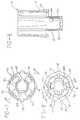
- Figs. 7-9provided detailed views of the cap 16 which is mounted to the open end of the sleeve 28.
- the capincludes a generally cylindrical outer wall 80 having four radially projecting ribs 18.
- the capfurther includes a generally cylindrical inner wall 82 which is coaxial with the outer wall 80.
- the inner wall 82includes a pair of opposing slots 84 at the bottom end thereof.
- Each of the opposing wall portions adjoining the slotsincludes a radially inwardly extending rim 86.
- a radially inwardly extending projection 88is formed at the top of each slot 84.
- the rubber shield 36 for the needle 38shown in Fig. 2, includes a relatively thick wall 36A at its open end which is maintained between the rim 86 and projections 88.
- Two pairs of opposing, radially inwardly extending projections 90are integral with the lower end of the outer wall 80 of the cap. As discussed below, these projections function as locking members which are engageable with a locking member on the sleeve 28.
- Each projection 90includes a beveled lower surface and a top surface which extends substantially perpendicularly with respect to the longitudinal axis. The bevelled surface initially engages a locking member on the cap, allowing the locking member to snap behind the projection when axial force is exerted on the cap.
- Each groovehas a generally saw-toothed configuration in cross section.
- the groovesadjoin the end surface of the outer wall, as shown in Fig. 8, and are aligned with the respective ribs 18.
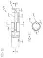
- Figs. 10-13provide detailed views of the sleeve 28 of the injection device.
- the sleeveincludes a generally cylindrical body having a longitudinal rib 28C extending from its lower surface.
- a notch 28B including a pair of vertical edgesis defined near the front portion of the rib 28C.
- a relatively short rib 28Gextends from the outer surface of the front portion of the sleeve, and is designed to fit within any of the grooves 92 in the inner surface of the cap 16.
- the front portion of the sleevefurther includes an elongate, deflectable finger 94, which is preferably integral with the sleeve body as shown.
- the fingerincludes a first, relatively small projection or rib 96 and a second, relatively large saw-toothed projection 98.
- the end of the finger near the front end of the sleeveis integral with the sleeve body. The opposite end is free.
- the fingeris positioned within an elongate slot 28H, and is deflectable about its connection to the sleeve body into the slot.
- the fingeris generally flush with the outer surface of the front portion of the sleeve.
- the first, relatively small projection 96 of the finger 94functions as a locking member when engaged with one of the radially extending projections 90 within the cap 16.
- the short rib 28G and grooves 92ensure that the locking members 96, 90 are aligned when the cap is mounted to the sleeve. Once the projection 96 has snapped behind one of the cap projections 90, the cap cannot be removed until the finger 94 is deflected well into the slot 28H. This can be accomplished manually by pushing the large projection 98 towards the slot 28H. It is preferably accomplished, however, by mounting the sleeve to the drive assembly and moving it into the firing position, as schematically shown in Fig. 14.
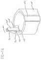
- Figs. 15-18provide detailed views of the collar 14, which is designed for interacting with the sleeve in an advantageous manner.
- the collarincludes a base which is snapped onto the drive assembly housing 12.
- a generally cylindrical portionis integral with the base.
- a first finger 14C including a pawlextends from the collar base to the rim.
- An axial slot 14Bis provided within the inner surface of the cylindrical portion of the collar. The slot 14B is located about forty degrees from the finger 14C.
- a projection 14Dextends downwardly from the cylindrical portion, and is located between the slot 14B and finger 14C. When the collar is mounted to the housing 12, the projection 14D is positioned in opposing relation to an axial rib 12D extending from the inner surface thereof
- a channelis defined between the projection 14D and rib 12D for receiving the longitudinal rib 28C of the sleeve 28. The channel is aligned with the slot 14B in the collar.
- the projection 14Dincludes an inclined surface 14E which allows a portion of the sleeve rib 28C to be rotated from the slot 14B into a second slot having a bottom wall defined by the finger 14C.
- Inclined surface 14Eprevents sleeve 28 from deviating from its rotational positioning once it has been rotated in place by a user.
- a second finger 14F including a second pawl 14Gis positioned in alignment with the slot 14B.
- the second fingeris deflectable about its connecting point to the cylindrical portion of the collar, and is substantially parallel to the first finger 14C.
- the second pawl 14Gis oriented such that the second finger is deflected by the longitudinal rib 28C of the sleeve as the sleeve is mounted to the drive assembly.
- the second pawlenters the notch 28B within the rib when the sleeve has been fully inserted.
- the sleeveis accordingly prevented from being withdrawn from the drive assembly housing once the second pawl has entered the sleeve notch.
- Fig. 19illustrates an alternative embodiment of the invention where the sleeve rib 28C defines a plurality of incremental stops in the form of saw-toothed ratchet teeth 100.
- each of the stopsengages the second pawl 14G, preventing sleeve withdrawal until the sleeve is rotated to the firing position.
- the walls defining the slot 14B and the sleeve ribare designed to permit sleeve rotation only upon full sleeve insertion. Rotation is then only possible in the direction of the inclined surface 14E and the first finger 14C.
- the portion of the collar opposite the finger 14Fis designed to interact with the deflectable finger 94 of the sleeve 28. It includes a notch bounded on one side by a shoulder 102 and on the opposite side by a ramp 104.
- the finger 94which is located one hundred eighty degrees from the rib 28C of the sleeve, enters the notch.
- Rotation of the sleeve into the firing positioncauses the ramp to bear against the relatively large projection 98 of the sleeve finger 94, thereby deflecting it radially inwardly. This causes the disengagement of the relatively small projection 96 and one of the radially inward projections 90 of the cap 16.
- the capmay accordingly be removed from the sleeve upon such disengagement by pulling it axially.
- the injection device 10when ready for use, includes a cartridge 30 containing the material to be injected.
- the piston 32is located towards the rear end of the cartridge.
- the radially inwardly extending projection 24B of the plug 24is located opposite the groove 54 in the rod 46.
- the driver 58is coupled to the drive rod 46.
- the push-button 66engages the driver 58, thereby preventing movement of the rod/driver assembly under the force of the constant force spring 56.
- the push-buttoncannot be depressed to release the rod/driver assembly as the sleeve projection 28A abuts the second engagement member 66B of the push-button.
- the cap 16is removed by pulling it forwardly along the longitudinal axis of the device.
- the shield 36is removed with the cap.
- the deviceotherwise remains unchanged from its original position.
- the end of the sleeve 28is pressed against the epidermis, thereby causing a force to be exerted thereon.
- the sleevemoves rearwardly against the force of the sleeve spring 40 for several millimeters, at which time the rear portion 44 of the sleeve engages a stop 12C extending from the housing 12. This movement is sufficient to displace the sleeve projection 28A a sufficient distance that it no longer interferes with the downward movement of the push-button 66.
- the projection 66C of the push-buttonis then pressed manually towards the housing, compressing spring 68 in the process. This causes displacement of the first engagement member 66A such that it no longer engages the driver 58.
- the driver 58 and rod 46move as a unit under the constant force of the spring 56, causing the syringe assembly 20 (via the plug 24) to move forwardly, and the needle 38 thereof to penetrate the skin.
- the compression of spring 68results in projection 66C being disposed against flats 74 of driver 58.
- the piston 32does not move.
- the projection 64 on the driver 58engages the projection 70 extending inwardly from the housing 12. This causes the pivotable arm 62 of the driver to rotate, and the pawl 60 to move out of the notch 52.
- the driver 58 and rodare decoupled at this point, which is just prior to the bottoming of the sleeve spring 40.
- the rod 46is urged forwardly as the rear end of the constant force spring 56 rotates within the saddle 48.
- the rodnow moves with respect to the driver 58, urging the piston 32 forwardly as fluid is displaced from the cartridge 30.
- the rodadvances through the plug 24 as the groove 54 is aligned with the plug projection 24B. Movement of the rod continues until the piston 32 engages the end wall of the cartridge 30.
- the ramp 50 of the rod 46engages the first engagement member 66A of the push-button near the end of its stroke, drawing the push-button entirely within the housing. This provides a visual end of dose indication.
- the sleeve 28is released once the second engagement member 66B is sufficiently displaced with respect to the sleeve projection 28A.
- the device 10Upon completion of the injection procedure, the device 10 is withdrawn from the body.
- the sleeve 28moves forwardly under the force of the sleeve spring to again cover the needle 38, and is releasably locked in position by the pawl 14A on the first collar finger 14C.
- the push-buttonremains within the housing, and accordingly cannot be actuated until a new syringe assembly is installed.
- the disposable portion of the deviceis disconnected from the reusable portion by grasping the sleeve 28 and pulling it in the axial direction. This causes the displacement of the pawl 14A from the notch 28B within the rib 28C of the sleeve.
- the cap 16can be replaced before or afier removal of the disposable portion of the device.
- a new syringe assemblyis installed by grasping the cap 16 and aligning the longitudinal rib 28C on the sleeve with the slot 14B in the collar. It can then be pushed into the housing until the cap 16 engages the collar 14.
- the plug projection 24Bis in opposing relation to the end surface 46A of the rod rather than the groove 54 within the rod. Insertion of the disposable portion of the device 10 accordingly causes the rod 46 to be pushed back into the housing 12.
- the wound end of the constant force spring 56rotates in the saddle as the rod is pushed.
- the rim of the plug 24pushes back the driver 58 during this procedure.
- the pawl 14G of the second finger 14F of the collarmoves within the notch 28B in the rib 28C, preventing removal of the disposable portion of the device once fully inserted.
- the disposable portioncan be rotated about an arc of forty degrees once it is pushed as far back as possible. Because the driver is pushed back with the rod, the push-button 66 springs back into the actuatable position as it moves partially within the gap of the driver. The driver pawl 60 moves into one of the notches 52 in the rod. The particular notch to be engaged by the pawl is determined by the length of the plug 24. If the piston 32 is located closer to the needle end of the cartridge, the nose portion of the plug will be longer such that is adjoins, but does not contact, the piston.
- rotation of the sleeve with respect to the collaralso causes the inward displacement of the sleeve finger 94 as the projection engages the ramp 104, thereby allowing the cap to be removed from the sleeve.
- the pawl 14Gis simultaneously rotated out of engagement with the notch 28B in the sleeve rib, which allows the sleeve to be removed once the device has been fired.
- the sleevemay include an engagement member and the housing a stop member, rather than vice versa , for preventing premature removal of the disposable portion of the device.
- a pair of springscould be used to drive the syringe assembly and piston, respectively.
- One or both springscould be constant force springs, preferably both.
- the drive assemblybe rearmed upon insertion of the syringe assembly, this step could also be accomplished as a separate procedure.
- the use of a constant force springfacilitates the rearming procedure regardless of which approach is employed. Rearming may also be accomplished without directly engaging the drive rod. It is sufficient that the rod be driven back against the force of the drive spring, whether by direct engagement of the rod or via an intermediate structure.
Landscapes
- Health & Medical Sciences (AREA)
- Vascular Medicine (AREA)
- Engineering & Computer Science (AREA)
- Anesthesiology (AREA)
- Biomedical Technology (AREA)
- Heart & Thoracic Surgery (AREA)
- Hematology (AREA)
- Life Sciences & Earth Sciences (AREA)
- Animal Behavior & Ethology (AREA)
- General Health & Medical Sciences (AREA)
- Public Health (AREA)
- Veterinary Medicine (AREA)
- Infusion, Injection, And Reservoir Apparatuses (AREA)
Abstract
Description

Claims (15)
- An assembly for storing and injecting a fluid, comprising:a sleeve (28), said sleeve including a first end anda second end;a syringe assembly (20) slidably positioned within saidsleeve, said syringe assembly including a cartridge (30),a piston (32) slidably positioned within said cartridge, anda needle (26) mounted to said cartridge, said needle extendingfrom said cartridge towards said first end of saidsleeve;a cap (16) removably mountable to said first end ofsaid sleeve;a first locking member positioned upon said cap (16);a second locking member positioned upon said sleeve(28), said second locking member being engageable with saidfirst locking member when said cap (16) is mounted to saidfirst end of said sleeve (28), anda lock release member positioned upon said sleeve (28),said lock release member being operatively associated withsaid second locking member.
- An assembly as described in claim 1 including an elongatefinger (94) coupled to said sleeve, said elongatefinger being radially deflectable with respect to the longitudinalaxis of said sleeve (28), said second locking memberand said lock release member being integral with said elongatefinger.
- An assembly as described in claim 2 wherein said finger(94) has a first end coupled to said sleeve (28) and a freesecond end, said sleeve including an elongate slot (28H)said finger being positioned within said slot.
- An assembly as described in Claim 3 wherein said secondlocking member is a projection extending from said finger(94) and said lock release member is a projection adjoiningsaid second end of said finger.
- An assembly as described in Claim 2 wherein said cap(16) includes a generally annular wall, said first lockingmember being a projection (14D) extending radially inwardlyfrom said annular wall.
- An assembly as described in Claim 5 wherein said projection(14D) includes a bevelled surface (14E) for initiallyengaging said second locking member when said cap ismounted to said sleeve.
- An assembly as described in Claim 5 wherein said cap(16) includes a plurality of first locking members extendingradially inwardly from said annular wall, said second lockingmember being engageable with a selected one of saidfirst locking members depending upon the rotational positionof said cap with respect to said sleeve (28).
- An automatic injection device comprising:a drive assembly including a housing (12) and a driverod slidably mounted within said housing;a syringe assembly including a cartridge (30), a piston(32) slidably mounted within said cartridge, and a needleassembly (26) mounted to said cartridge;means for resiliently urging said drive rod towardssaid syringe assembly;a sleeve (28) having a first end and a second end, saidsyringe assembly being positioned at least partially withinsaid sleeve, said second end of said sleeve being removablycoupled to said housing of said drive assembly;a cap (16) removably mounted to said first end of saidsleeve;a first locking member positioned upon said cap (16);a second locking member positioned upon said sleeve(28), said second locking member being engageable with saidfirst locking member when said cap (16) is mounted to saidfirst end of said sleeve (28), anda lock release assembly, said lock release assemblybeing operatively associated with at least one of said firstand second locking members such that said first and secondlocking members are disengaged upon rotation of said sleeve(28) with respect to said housing of said drive assembly.
- A device as described in Claim 8 including an elongatefinger (94) coupled to said sleeve (28), said elongatefinger being radially deflectable with respect to the longitudinalaxis of said sleeve (28), said second locking memberbeing integral with said elongate finger.
- A device as described in Claim 9 wherein said finger(94) has a first end coupled to said sleeve and a freesecond end, said sleeve (28) including an elongate slot(28H), said finger being deflectable into said slot.
- A device as described in Claim 9 wherein said lockrelease assembly includes a projection extending from saidfinger (94) and an engagement surface on said housing, saidengagement surface engaging said projection upon rotationof said sleeve (28) with respect to said housing (12),thereby deflecting said elongate finger and causing disengagementof said first and second locking members.
- A device as described in Claim 11 wherein said engagementsurface includes a ramp.
- A device as described in Claim 9 wherein said cap (16)includes a generally annular wall, said first locking memberbeing a projection extending radially inwardly from saidannular wall.
- A device as described in Claim 13 wherein said projectionincludes a bevelled surface for initially engagingsaid second locking member.
- A device as described in Claim 13 wherein said cap (16)includes a plurality of first locking members extendingradially inwardly from said annular wall, said second lockingmember being engageable with a selected one of saidfirst locking members depending upon the rotational positionof said cap (16) with respect to said sleeve (28).
Priority Applications (1)
| Application Number | Priority Date | Filing Date | Title |
|---|---|---|---|
| EP02025483AEP1285674B1 (en) | 1996-08-23 | 1997-08-19 | A non-dosing cartridge for an injection device |
Applications Claiming Priority (2)
| Application Number | Priority Date | Filing Date | Title |
|---|---|---|---|
| US701962 | 1996-08-23 | ||
| US08/701,962US5843036A (en) | 1996-08-23 | 1996-08-23 | Non-dosing cartridge for an injection device |
Related Child Applications (1)
| Application Number | Title | Priority Date | Filing Date |
|---|---|---|---|
| EP02025483ADivisionEP1285674B1 (en) | 1996-08-23 | 1997-08-19 | A non-dosing cartridge for an injection device |
Publications (2)
| Publication Number | Publication Date |
|---|---|
| EP0824923A1true EP0824923A1 (en) | 1998-02-25 |
| EP0824923B1 EP0824923B1 (en) | 2003-07-23 |
Family
ID=24819373
Family Applications (2)
| Application Number | Title | Priority Date | Filing Date |
|---|---|---|---|
| EP02025483AExpired - LifetimeEP1285674B1 (en) | 1996-08-23 | 1997-08-19 | A non-dosing cartridge for an injection device |
| EP97114272AExpired - LifetimeEP0824923B1 (en) | 1996-08-23 | 1997-08-19 | Cartrigde with temporarily lockable cap for an injection device |
Family Applications Before (1)
| Application Number | Title | Priority Date | Filing Date |
|---|---|---|---|
| EP02025483AExpired - LifetimeEP1285674B1 (en) | 1996-08-23 | 1997-08-19 | A non-dosing cartridge for an injection device |
Country Status (9)
| Country | Link |
|---|---|
| US (1) | US5843036A (en) |
| EP (2) | EP1285674B1 (en) |
| JP (1) | JP3168179B2 (en) |
| KR (1) | KR19980018907A (en) |
| BR (1) | BR9710922A (en) |
| CA (1) | CA2211732A1 (en) |
| DE (2) | DE69733910T2 (en) |
| ES (2) | ES2246370T3 (en) |
| TW (1) | TW349026B (en) |
Cited By (34)
| Publication number | Priority date | Publication date | Assignee | Title |
|---|---|---|---|---|
| EP0956873A3 (en)* | 1998-05-15 | 2000-07-26 | Disetronic Licensing AG | Automatic injection device |
| WO2004054644A1 (en)* | 2002-12-17 | 2004-07-01 | Safe-T Limited | Hollow needle applicators |
| WO2005044345A1 (en)* | 2003-11-05 | 2005-05-19 | Tecpharma Licensing Ag | Autoinjection device |
| WO2005058396A1 (en)* | 2003-12-18 | 2005-06-30 | Tecpharma Licensing Ag | Releasable injection device |
| EP1349590B1 (en)* | 2000-12-14 | 2006-05-31 | SHL Medical AB | Auto-injector |
| WO2007036676A1 (en)* | 2005-09-27 | 2007-04-05 | Cilag Gmbh International | Auto-injection device with needle protecting cap having outer and inner sleeves |
| WO2010035056A1 (en)* | 2008-09-29 | 2010-04-01 | Becton Dickinson France | Automatic injection device with sensitive indicator of completed injection |
| EP2204201A1 (en)* | 2004-08-06 | 2010-07-07 | Meridian Medical Technologies, Inc. | Automatic injector |
| WO2011112136A1 (en)* | 2010-03-09 | 2011-09-15 | Shl Group Ab | Medicament delivery device |
| US8048035B2 (en) | 2004-08-06 | 2011-11-01 | Meridian Medical Technologies, Inc. | Automatic injector with needle cover |
| WO2012164397A1 (en)* | 2011-06-02 | 2012-12-06 | Beucb Pharma S.A. | Auto-injector |
| EP2703022A1 (en)* | 2012-09-03 | 2014-03-05 | LTS LOHMANN Therapie-Systeme AG | One-off injector with two step disengagement |
| USD726901S1 (en) | 2012-07-30 | 2015-04-14 | Ucb Pharma S.A. | Drive device for administering medication |
| EP2907537A1 (en)* | 2009-05-01 | 2015-08-19 | Owen Mumford Limited | Injection devices |
| EP2076299B1 (en) | 2006-09-06 | 2017-07-19 | Becton Dickinson France | Automatic injection device with temporizing means |
| US9757521B2 (en) | 2012-07-30 | 2017-09-12 | Ucb Biopharma Sprl | Auto-injector |
| US9757513B2 (en) | 2012-07-30 | 2017-09-12 | Ucb Biopharma Sprl | Auto-injector |
| US9757524B2 (en) | 2012-07-30 | 2017-09-12 | Ucb Biopharma Sprl | Auto-injector |
| US9764101B2 (en) | 2012-07-30 | 2017-09-19 | Ucb Biopharma Sprl | Auto-injector |
| US9789254B2 (en) | 2014-01-27 | 2017-10-17 | Ucb Biopharma Sprl | Auto-injector |
| US9821123B2 (en) | 2014-01-27 | 2017-11-21 | Ucb Biopharma Sprl | Auto-injector |
| CN107441595A (en)* | 2016-05-30 | 2017-12-08 | Epic医疗私人有限公司 | Liquid transporting apparatus and system |
| US9901686B2 (en) | 2008-01-11 | 2018-02-27 | Ucb Biopharma Sprl | Systems and methods for administering medication |
| US10314985B2 (en) | 2009-08-19 | 2019-06-11 | Safety Syringes, Inc. | Patient-contact activated needle stick safety device |
| US10342925B2 (en) | 2014-01-27 | 2019-07-09 | Ucb Biopharma Sprl | Auto-injector |
| USRE47903E1 (en) | 2010-12-21 | 2020-03-17 | Sanofi-Aventis Deutschland Gmbh | Auto-injector |
| USRE48593E1 (en) | 2010-12-21 | 2021-06-15 | Sanofi-Aventis Deutschland Gmbh | Auto-injector |
| EP2010252B2 (en)† | 2006-04-12 | 2021-08-18 | TecPharma Licensing AG | Injection device with tensioning spring and tensioning element |
| US11400217B2 (en) | 2010-12-21 | 2022-08-02 | Sanofi-Aventis Deutschland Gmbh | Auto-injector |
| US11484653B1 (en) | 2010-02-18 | 2022-11-01 | Sanofi-Aventis Deutschland Gmbh | Auto-injector |
| US11504475B2 (en) | 2010-06-28 | 2022-11-22 | Sanofi-Aventis Deutschland Gmbh | Auto-injector |
| US12042636B2 (en) | 2015-06-03 | 2024-07-23 | Sanofi-Aventis Deutschland Gmbh | Syringe support and autoinjector |
| US12076541B2 (en) | 2011-12-21 | 2024-09-03 | Sanofi-Aventis Deutschland Gmbh | Autoinjector with an inner plunger which disengages the outer plunger to retract the syringe carrier |
| US12208247B2 (en) | 2011-02-18 | 2025-01-28 | Sanofi-Aventis Deutschland Gmbh | Auto-injector |
Families Citing this family (121)
| Publication number | Priority date | Publication date | Assignee | Title |
|---|---|---|---|---|
| CZ297361B6 (en) | 1998-01-30 | 2006-11-15 | Novo Nordisk A/S | Injection syringe |
| US6319233B1 (en)* | 1998-04-17 | 2001-11-20 | Becton, Dickinson And Company | Safety shield system for prefilled syringes |
| US6679864B2 (en) | 1998-04-17 | 2004-01-20 | Becton Dickinson And Company | Safety shield system for prefilled syringes |
| US6719730B2 (en) | 1998-04-17 | 2004-04-13 | Becton, Dickinson And Company | Safety shield system for prefilled syringes |
| DE19819409A1 (en)* | 1998-04-30 | 1999-11-11 | Schering Ag | Injection device |
| SE9803662D0 (en) | 1998-10-26 | 1998-10-26 | Pharmacia & Upjohn Ab | autoinjector |
| USD428651S (en)* | 1998-10-26 | 2000-07-25 | Pharmacia & Upjohn Ab | Autoinjector for standardized single dose syringes |
| TW453884B (en) | 1999-09-16 | 2001-09-11 | Novo Nordisk As | Dose setting limiter |
| FR2799375B1 (en)* | 1999-10-07 | 2002-01-18 | Marc Brunel | SINGLE USE INJECTION DEVICE |
| US6547764B2 (en) | 2000-05-31 | 2003-04-15 | Novo Nordisk A/S | Double pointed injection needle |
| US6663602B2 (en) | 2000-06-16 | 2003-12-16 | Novo Nordisk A/S | Injection device |
| EP3138598B1 (en)* | 2000-08-02 | 2019-10-23 | Becton, Dickinson and Company | Pen needle and safety shield system |
| US6986760B2 (en) | 2000-08-02 | 2006-01-17 | Becton, Dickinson And Company | Pen needle and safety shield system |
| DE10046279A1 (en)* | 2000-09-19 | 2002-04-04 | Disetronic Licensing Ag | Device for the dosed administration of an injectable product |
| WO2003045480A1 (en) | 2001-11-30 | 2003-06-05 | Novo Nordisk A/S | A safety needle assembly |
| WO2003068290A2 (en) | 2002-02-11 | 2003-08-21 | Antares Pharma, Inc. | Intradermal injector |
| EP2210634A1 (en)* | 2009-01-22 | 2010-07-28 | Sanofi-Aventis Deutschland GmbH | Drug delivery device dose setting mechanism |
| GB0304822D0 (en) | 2003-03-03 | 2003-04-09 | Dca Internat Ltd | Improvements in and relating to a pen-type injector |
| GB0308267D0 (en) | 2003-04-10 | 2003-05-14 | Dca Design Int Ltd | Improvements in and relating to a pen-type injector |
| US8932264B2 (en) | 2003-08-11 | 2015-01-13 | Becton, Dickinson And Company | Medication delivery pen assembly with needle locking safety shield |
| DE10342058B4 (en)* | 2003-09-11 | 2007-10-25 | Tecpharma Licensing Ag | Administration device for an injectable product with a trigger safety device |
| IL157981A (en) | 2003-09-17 | 2014-01-30 | Elcam Medical Agricultural Cooperative Ass Ltd | Auto-injector |
| EP1689465A4 (en)* | 2003-12-05 | 2011-10-12 | Zogenix Inc | A device for readying a needle free injector for delivery |
| CN100574821C (en)* | 2003-12-18 | 2009-12-30 | 特克法马许可公司 | releasable injection device |
| IL160891A0 (en) | 2004-03-16 | 2004-08-31 | Auto-mix needle | |
| US20050215923A1 (en)* | 2004-03-26 | 2005-09-29 | Wiegel Christopher D | Fingertip conforming fluid expression cap |
| US7470253B2 (en)* | 2004-05-26 | 2008-12-30 | Bioquiddity, Inc. | Fluid delivery apparatus with adjustable flow rate control |
| GB2414404B (en) | 2004-05-28 | 2009-06-03 | Cilag Ag Int | Injection device |
| GB2414401B (en) | 2004-05-28 | 2009-06-17 | Cilag Ag Int | Injection device |
| GB2414400B (en) | 2004-05-28 | 2009-01-14 | Cilag Ag Int | Injection device |
| GB2414403B (en) | 2004-05-28 | 2009-01-07 | Cilag Ag Int | Injection device |
| GB2414402B (en) | 2004-05-28 | 2009-04-22 | Cilag Ag Int | Injection device |
| GB2414405B (en) | 2004-05-28 | 2009-01-14 | Cilag Ag Int | Injection device |
| GB2414399B (en) | 2004-05-28 | 2008-12-31 | Cilag Ag Int | Injection device |
| GB2414406B (en) | 2004-05-28 | 2009-03-18 | Cilag Ag Int | Injection device |
| GB2414409B (en) | 2004-05-28 | 2009-11-18 | Cilag Ag Int | Injection device |
| GB2414775B (en) | 2004-05-28 | 2008-05-21 | Cilag Ag Int | Releasable coupling and injection device |
| GB0414054D0 (en) | 2004-06-23 | 2004-07-28 | Owen Mumford Ltd | Improvements relating to automatic injection devices |
| ATE444090T1 (en) | 2004-10-21 | 2009-10-15 | Novo Nordisk As | SELECTION MECHANISM FOR A ROTARY PIN |
| HUE042286T2 (en) | 2005-01-24 | 2019-06-28 | Antares Pharma Inc | Needle-filled pre-filled syringe |
| GB2427826B (en) | 2005-04-06 | 2010-08-25 | Cilag Ag Int | Injection device comprising a locking mechanism associated with integrally formed biasing means |
| GB2424836B (en) | 2005-04-06 | 2010-09-22 | Cilag Ag Int | Injection device (bayonet cap removal) |
| GB2424835B (en) | 2005-04-06 | 2010-06-09 | Cilag Ag Int | Injection device (modified trigger) |
| GB2424838B (en) | 2005-04-06 | 2011-02-23 | Cilag Ag Int | Injection device (adaptable drive) |
| GB2425062B (en) | 2005-04-06 | 2010-07-21 | Cilag Ag Int | Injection device |
| FR2884721A1 (en)* | 2005-04-20 | 2006-10-27 | Becton Dickinson France Soc Pa | Assistance device for device of injection of a product, comprises hollow body for receiving the product, hollow injection needle for penetrating into injection site, piston placed in the body, hollow sleeve with bearing surface |
| US20090043264A1 (en) | 2005-04-24 | 2009-02-12 | Novo Nordisk A/S | Injection Device |
| PL1759729T3 (en) | 2005-08-30 | 2010-09-30 | Cilag Gmbh Int | Needle assembly for a prefilled syringe system |
| US8425460B2 (en)* | 2005-09-01 | 2013-04-23 | Owen Mumford Limited | Needle shroud assembly |
| CN101400394B (en) | 2006-03-10 | 2012-07-04 | 诺沃-诺迪斯克有限公司 | An injection device having a gearing arrangement |
| JP5062768B2 (en) | 2006-03-10 | 2012-10-31 | ノボ・ノルデイスク・エー/エス | INJECTION DEVICE AND METHOD FOR REPLACING CARTRIDGE OF THE DEVICE |
| WO2007131025A1 (en) | 2006-05-03 | 2007-11-15 | Antares Pharma, Inc. | Injector with adjustable dosing |
| WO2007131013A1 (en) | 2006-05-03 | 2007-11-15 | Antares Pharma, Inc. | Two-stage reconstituting injector |
| ATE458517T1 (en) | 2006-05-16 | 2010-03-15 | Novo Nordisk As | TRANSMISSION MECHANISM FOR AN INJECTION DEVICE |
| JP5253387B2 (en) | 2006-05-18 | 2013-07-31 | ノボ・ノルデイスク・エー/エス | Injection device with mode locking means |
| GB2438591B (en) | 2006-06-01 | 2011-07-13 | Cilag Gmbh Int | Injection device |
| GB2438590B (en) | 2006-06-01 | 2011-02-09 | Cilag Gmbh Int | Injection device |
| GB2438593B (en)* | 2006-06-01 | 2011-03-30 | Cilag Gmbh Int | Injection device (cap removal feature) |
| KR101396797B1 (en) | 2006-06-30 | 2014-05-26 | 애브비 바이오테크놀로지 리미티드 | Automatic injection device |
| EP2109474B2 (en) | 2007-02-05 | 2019-01-30 | Novo Nordisk A/S | Injection button |
| EP2129414A1 (en)* | 2007-03-22 | 2009-12-09 | Tecpharma Licensing AG | Injection device having trigger safety devices |
| BRPI0809265A2 (en) | 2007-03-23 | 2014-10-07 | Novo Nordisk As | INJECTION DEVICE INCLUDING A TIGHTENING NUT |
| GB2452030A (en)* | 2007-08-10 | 2009-02-25 | Owen Mumford Ltd | Injection devices |
| EP3636301A1 (en) | 2008-03-10 | 2020-04-15 | Antares Pharma, Inc. | Injector safety device |
| US8177749B2 (en)* | 2008-05-20 | 2012-05-15 | Avant Medical Corp. | Cassette for a hidden injection needle |
| US8052645B2 (en) | 2008-07-23 | 2011-11-08 | Avant Medical Corp. | System and method for an injection using a syringe needle |
| CA3070618C (en) | 2008-05-20 | 2021-07-20 | Avant Medical Corp. | Autoinjector system |
| GB2461086B (en) | 2008-06-19 | 2012-12-05 | Cilag Gmbh Int | Injection device |
| GB2461085B (en) | 2008-06-19 | 2012-08-29 | Cilag Gmbh Int | Injection device |
| GB2461089B (en) | 2008-06-19 | 2012-09-19 | Cilag Gmbh Int | Injection device |
| GB2461087B (en) | 2008-06-19 | 2012-09-26 | Cilag Gmbh Int | Injection device |
| GB2461084B (en) | 2008-06-19 | 2012-09-26 | Cilag Gmbh Int | Fluid transfer assembly |
| WO2009155277A1 (en)* | 2008-06-20 | 2009-12-23 | West Pharmaceutical Services, Inc. | Automatic injection mechanism with frontal buttress |
| US8048029B2 (en)* | 2008-06-20 | 2011-11-01 | West Pharmaceutical Services, Inc. | Injector apparatus |
| US8376993B2 (en) | 2008-08-05 | 2013-02-19 | Antares Pharma, Inc. | Multiple dosage injector |
| EP2362968B1 (en)* | 2008-11-05 | 2016-01-27 | West Pharmaceutical Services, Inc. | Barrier isolator port assembly |
| GB0823693D0 (en) | 2008-12-31 | 2009-02-04 | Owen Mumford Ltd | Autoinjector |
| GB0900930D0 (en) | 2009-01-20 | 2009-03-04 | Future Injection Technologies Ltd | Injection device |
| JP5732039B2 (en) | 2009-03-20 | 2015-06-10 | アンタレス・ファーマ・インコーポレーテッド | Hazardous drug injection system |
| WO2010127146A1 (en) | 2009-04-29 | 2010-11-04 | Abbott Biotechnology Ltd | Automatic injection device |
| EP2512558A4 (en) | 2009-12-15 | 2014-08-13 | Abbvie Biotechnology Ltd | IMPROVED TRIP PUSHER FOR AUTOMATIC INJECTION DEVICE |
| NZ702172A (en) | 2010-04-21 | 2016-03-31 | Abbvie Biotechnology Ltd | Wearable automatic injection device for controlled delivery of therapeutic agents |
| KR101989342B1 (en) | 2011-01-24 | 2019-06-14 | 애브비 바이오테크놀로지 리미티드 | Removal of needle shields from syringes and automatic injection devices |
| ES2710905T3 (en) | 2011-01-24 | 2019-04-29 | E3D Agricultural Coop Association Ltd | Injector |
| BR112013018905B1 (en) | 2011-01-24 | 2021-07-13 | Abbvie Biotechnology Ltd | AUTOMATIC INJECTION DEVICES THAT HAVE OVERMOLDED HANDLE SURFACES. |
| PL2699293T3 (en) | 2011-04-20 | 2019-08-30 | Amgen Inc. | Autoinjector apparatus |
| US9220660B2 (en) | 2011-07-15 | 2015-12-29 | Antares Pharma, Inc. | Liquid-transfer adapter beveled spike |
| US8496619B2 (en) | 2011-07-15 | 2013-07-30 | Antares Pharma, Inc. | Injection device with cammed ram assembly |
| JP6069351B2 (en) | 2011-12-29 | 2017-02-01 | ノボ・ノルデイスク・エー/エス | Torsion spring type automatic syringe with dial-up / dial-down administration mechanism |
| US9486583B2 (en) | 2012-03-06 | 2016-11-08 | Antares Pharma, Inc. | Prefilled syringe with breakaway force feature |
| EP4186545A1 (en) | 2012-04-06 | 2023-05-31 | Antares Pharma, Inc. | Needle assisted jet injection administration of testosterone compositions |
| USD898908S1 (en) | 2012-04-20 | 2020-10-13 | Amgen Inc. | Pharmaceutical product cassette for an injection device |
| USD808010S1 (en) | 2012-04-20 | 2018-01-16 | Amgen Inc. | Injection device |
| US9364610B2 (en) | 2012-05-07 | 2016-06-14 | Antares Pharma, Inc. | Injection device with cammed ram assembly |
| USD724203S1 (en) | 2012-06-04 | 2015-03-10 | Ucb Pharma S.A. | Drive device for administering medication |
| FI3659647T3 (en) | 2013-02-11 | 2024-03-28 | Antares Pharma Inc | NEEDLE-ASSISTED SPRAY INJECTOR WITH REDUCED TRIGGER FORCE |
| CA2905031C (en) | 2013-03-11 | 2018-01-23 | Hans PFLAUMER | Dosage injector with pinion system |
| WO2014165136A1 (en) | 2013-03-12 | 2014-10-09 | Antares Pharma, Inc. | Constant volume prefilled syringes and kits thereof |
| ES2973257T3 (en) | 2013-03-15 | 2024-06-19 | Amgen Inc | Drug cassette, autoinjector and autoinjector system |
| CA2904661C (en) | 2013-03-15 | 2022-03-15 | Amgen Inc. | Drug cassette, autoinjector, and autoinjector system |
| GB2515032A (en) | 2013-06-11 | 2014-12-17 | Cilag Gmbh Int | Guide for an injection device |
| GB2515038A (en) | 2013-06-11 | 2014-12-17 | Cilag Gmbh Int | Injection device |
| GB2515039B (en) | 2013-06-11 | 2015-05-27 | Cilag Gmbh Int | Injection Device |
| GB2517896B (en) | 2013-06-11 | 2015-07-08 | Cilag Gmbh Int | Injection device |
| WO2015118550A2 (en) | 2014-02-10 | 2015-08-13 | Elcam Medical Agricultural Cooperative Association Ltd. | Semi disposable auto injector |
| CN104307072A (en)* | 2014-10-29 | 2015-01-28 | 杭州普昂医疗科技有限公司 | Safety insulin pen |
| US10850036B2 (en) | 2015-08-27 | 2020-12-01 | E3D Agricultural Cooperative Association | Reusable automatic injection device |
| GB201607491D0 (en)* | 2016-04-29 | 2016-06-15 | Owen Mumford Ltd | Injection devices |
| DK3452143T3 (en)* | 2016-05-06 | 2020-09-07 | Sanofi Aventis Deutschland | INJECTOR FACILITY |
| US10792437B2 (en)* | 2016-06-21 | 2020-10-06 | Shl Medical Ag | Safety mechanism for a push-off cap of a medicament delivery device |
| CH712753A2 (en) | 2016-07-28 | 2018-01-31 | Tecpharma Licensing Ag | Separating a needle cap from a product container and method of mounting an injection device. |
| DE102017208255A1 (en)* | 2017-05-16 | 2018-11-22 | Vetter Pharma-Fertigung GmbH & Co. KG | Medicament container having an end plug, use of a stopper securing member for securing an end plug in a medicament container and stopper securing member |
| KR20240055848A (en) | 2017-06-30 | 2024-04-29 | 리제너론 파아마슈티컬스, 인크. | Auto-injector with anti-roll features |
| RS65380B1 (en) | 2017-08-24 | 2024-04-30 | Novo Nordisk As | Glp-1 compositions and uses thereof |
| JP1629334S (en) | 2017-10-25 | 2019-04-15 | ||
| EP3710090A1 (en)* | 2017-11-16 | 2020-09-23 | Amgen Inc. | Door latch mechanism for drug delivery device |
| USD932006S1 (en) | 2018-11-21 | 2021-09-28 | Regeneron Pharmaceuticals, Inc. | Auto-injector cap |
| USD903856S1 (en) | 2018-06-29 | 2020-12-01 | Regeneron Pharmaceuticals, Inc. | Auto-injector |
| IL294520A (en) | 2020-02-18 | 2022-09-01 | Novo Nordisk As | Pharmaceutical formulations |
| EP4460349A1 (en)* | 2022-01-03 | 2024-11-13 | SHL Medical AG | A sub-assembly of a medicament cassette unit |
| WO2025132686A1 (en)* | 2023-12-21 | 2025-06-26 | Sanofi | A medicament delivey system |
Citations (8)
| Publication number | Priority date | Publication date | Assignee | Title |
|---|---|---|---|---|
| US2752918A (en) | 1949-08-17 | 1956-07-03 | Auguste Rooseboom | Hypodermic injection apparatus |
| US3797489A (en) | 1972-02-10 | 1974-03-19 | Survival Technology | Hypodermic injection device with shock absorbing spring |
| US4484910A (en) | 1983-12-21 | 1984-11-27 | Survival Technology, Inc. | Dual mode automatic injector |
| US4902279A (en) | 1988-10-05 | 1990-02-20 | Autoject Systems Inc. | Liquid medicament safety injector |
| US5114404A (en) | 1990-07-24 | 1992-05-19 | Paxton Gerald R | Multifunctional retractable needle type general purpose disabling syringe having enhanced safety features and related method of operation |
| US5137516A (en) | 1989-11-28 | 1992-08-11 | Glaxo Group Limited | Triggered application device for medicament to be more descriptive of the invention |
| US5425715A (en) | 1993-08-05 | 1995-06-20 | Survival Technology, Inc. | Reloadable injector |
| US5478316A (en) | 1994-02-02 | 1995-12-26 | Becton, Dickinson And Company | Automatic self-injection device |
Family Cites Families (1)
| Publication number | Priority date | Publication date | Assignee | Title |
|---|---|---|---|---|
| US5320609A (en)* | 1992-12-07 | 1994-06-14 | Habley Medical Technology Corporation | Automatic pharmaceutical dispensing syringe |
- 1996
- 1996-08-23USUS08/701,962patent/US5843036A/ennot_activeExpired - Lifetime
- 1997
- 1997-07-30CACA002211732Apatent/CA2211732A1/ennot_activeAbandoned
- 1997-08-11BRBR9710922-3Apatent/BR9710922A/ennot_activeApplication Discontinuation
- 1997-08-19EPEP02025483Apatent/EP1285674B1/ennot_activeExpired - Lifetime
- 1997-08-19ESES02025483Tpatent/ES2246370T3/ennot_activeExpired - Lifetime
- 1997-08-19DEDE69733910Tpatent/DE69733910T2/ennot_activeExpired - Lifetime
- 1997-08-19EPEP97114272Apatent/EP0824923B1/ennot_activeExpired - Lifetime
- 1997-08-19DEDE69723627Tpatent/DE69723627T2/ennot_activeExpired - Lifetime
- 1997-08-19ESES97114272Tpatent/ES2201230T3/ennot_activeExpired - Lifetime
- 1997-08-22KRKR1019970040156Apatent/KR19980018907A/ennot_activeWithdrawn
- 1997-08-25JPJP22853397Apatent/JP3168179B2/ennot_activeExpired - Lifetime
- 1997-10-20TWTW086112164Apatent/TW349026B/enactive
Patent Citations (8)
| Publication number | Priority date | Publication date | Assignee | Title |
|---|---|---|---|---|
| US2752918A (en) | 1949-08-17 | 1956-07-03 | Auguste Rooseboom | Hypodermic injection apparatus |
| US3797489A (en) | 1972-02-10 | 1974-03-19 | Survival Technology | Hypodermic injection device with shock absorbing spring |
| US4484910A (en) | 1983-12-21 | 1984-11-27 | Survival Technology, Inc. | Dual mode automatic injector |
| US4902279A (en) | 1988-10-05 | 1990-02-20 | Autoject Systems Inc. | Liquid medicament safety injector |
| US5137516A (en) | 1989-11-28 | 1992-08-11 | Glaxo Group Limited | Triggered application device for medicament to be more descriptive of the invention |
| US5114404A (en) | 1990-07-24 | 1992-05-19 | Paxton Gerald R | Multifunctional retractable needle type general purpose disabling syringe having enhanced safety features and related method of operation |
| US5425715A (en) | 1993-08-05 | 1995-06-20 | Survival Technology, Inc. | Reloadable injector |
| US5478316A (en) | 1994-02-02 | 1995-12-26 | Becton, Dickinson And Company | Automatic self-injection device |
Cited By (117)
| Publication number | Priority date | Publication date | Assignee | Title |
|---|---|---|---|---|
| EP1568388A1 (en)* | 1998-05-15 | 2005-08-31 | Tecpharma Licensing AG | Automatic injection device |
| EP0956873A3 (en)* | 1998-05-15 | 2000-07-26 | Disetronic Licensing AG | Automatic injection device |
| EP1875935A3 (en)* | 1998-05-15 | 2008-05-21 | Tecpharma Licensing AG | Automatic injection device |
| EP1349590B1 (en)* | 2000-12-14 | 2006-05-31 | SHL Medical AB | Auto-injector |
| US7442185B2 (en) | 2000-12-14 | 2008-10-28 | Shl Group Ab | Auto-injector |
| WO2004054644A1 (en)* | 2002-12-17 | 2004-07-01 | Safe-T Limited | Hollow needle applicators |
| AU2003292410B2 (en)* | 2002-12-17 | 2008-12-18 | Safe-T Limited | Hollow needle applicators |
| WO2005044345A1 (en)* | 2003-11-05 | 2005-05-19 | Tecpharma Licensing Ag | Autoinjection device |
| AU2004298302B2 (en)* | 2003-12-18 | 2009-04-02 | Tecpharma Licensing Ag | Releasable injection device |
| WO2005058396A1 (en)* | 2003-12-18 | 2005-06-30 | Tecpharma Licensing Ag | Releasable injection device |
| US9586010B2 (en) | 2004-08-06 | 2017-03-07 | Meridian Medical Technologies, Inc. | Automatic injector with needle cover |
| US8870827B2 (en) | 2004-08-06 | 2014-10-28 | Meridian Medical Technologies, Inc. | Automatic injector |
| EP2204201A1 (en)* | 2004-08-06 | 2010-07-07 | Meridian Medical Technologies, Inc. | Automatic injector |
| US7794432B2 (en) | 2004-08-06 | 2010-09-14 | Meridian Medical Technologies, Inc. | Automatic injector with kickback attenuation |
| EP2204201B1 (en) | 2004-08-06 | 2020-04-15 | Meridian Medical Technologies, Inc. | Automatic injector |
| US8048035B2 (en) | 2004-08-06 | 2011-11-01 | Meridian Medical Technologies, Inc. | Automatic injector with needle cover |
| EA014438B1 (en)* | 2005-09-27 | 2010-12-30 | Цилаг Гмбх Интернэшнл | Auto-injection device with needle protecting cap having outer and inner sleeves |
| WO2007036676A1 (en)* | 2005-09-27 | 2007-04-05 | Cilag Gmbh International | Auto-injection device with needle protecting cap having outer and inner sleeves |
| EP2010252B2 (en)† | 2006-04-12 | 2021-08-18 | TecPharma Licensing AG | Injection device with tensioning spring and tensioning element |
| EP2076299B1 (en) | 2006-09-06 | 2017-07-19 | Becton Dickinson France | Automatic injection device with temporizing means |
| US9901686B2 (en) | 2008-01-11 | 2018-02-27 | Ucb Biopharma Sprl | Systems and methods for administering medication |
| US10661023B2 (en) | 2008-01-11 | 2020-05-26 | Ucb Bioparma Sprl | Systems and methods for administering medication |
| WO2010035056A1 (en)* | 2008-09-29 | 2010-04-01 | Becton Dickinson France | Automatic injection device with sensitive indicator of completed injection |
| US9302054B2 (en) | 2009-05-01 | 2016-04-05 | Owen Mumford Limited | Injection devices |
| EP3266479A1 (en)* | 2009-05-01 | 2018-01-10 | Owen Mumford Limited | Injection device |
| EP2907537A1 (en)* | 2009-05-01 | 2015-08-19 | Owen Mumford Limited | Injection devices |
| US10314985B2 (en) | 2009-08-19 | 2019-06-11 | Safety Syringes, Inc. | Patient-contact activated needle stick safety device |
| US11400234B2 (en) | 2009-08-19 | 2022-08-02 | Safety Syringes, Inc. | Patient-contact activated needle stick safety device |
| US12409273B2 (en) | 2010-02-18 | 2025-09-09 | Sanofi-Aventis Deutschland Gmbh | Auto-injector |
| US11484653B1 (en) | 2010-02-18 | 2022-11-01 | Sanofi-Aventis Deutschland Gmbh | Auto-injector |
| US12397117B2 (en) | 2010-02-18 | 2025-08-26 | Sanofi-Aventis Deutschland Gmbh | Auto-injector |
| US12090302B2 (en) | 2010-02-18 | 2024-09-17 | Sanofi-Aventis Deutschland Gmbh | Auto-injector |
| US12409274B2 (en) | 2010-02-18 | 2025-09-09 | Sanofi-Aventis Deutschland Gmbh | Auto-injector |
| US12083319B2 (en) | 2010-02-18 | 2024-09-10 | Sanofi-Aventis Deutschland Gmbh | Auto-injector |
| US11730888B2 (en) | 2010-02-18 | 2023-08-22 | Sanofi-Aventis Deutschland Gmbh | Auto-injector |
| US12090303B2 (en) | 2010-02-18 | 2024-09-17 | Sanofi-Aventis Deutschland Gmbh | Auto-injector |
| US12390593B2 (en) | 2010-02-18 | 2025-08-19 | Sanofi-Aventis Deutschland Gmbh | Auto-injector |
| US12427257B2 (en) | 2010-02-18 | 2025-09-30 | Sanofi-Aventis Deutschland Gmbh | Auto-injector |
| US12397116B2 (en) | 2010-02-18 | 2025-08-26 | Sanofi-Aventis Deutschland Gmbh | Auto-injector |
| WO2011112136A1 (en)* | 2010-03-09 | 2011-09-15 | Shl Group Ab | Medicament delivery device |
| AU2011224884B2 (en)* | 2010-03-09 | 2013-08-15 | Shl Medical Ag | Medicament delivery device |
| US9061104B2 (en) | 2010-03-09 | 2015-06-23 | Shl Group Ab | Medicament injection device |
| US12318585B2 (en) | 2010-06-28 | 2025-06-03 | Sanofi-Aventis Deutschland Gmbh | Auto-injector |
| US12329935B2 (en) | 2010-06-28 | 2025-06-17 | Sanofi-Aventis Deutschland Gmbh | Auto-injector |
| US11504475B2 (en) | 2010-06-28 | 2022-11-22 | Sanofi-Aventis Deutschland Gmbh | Auto-injector |
| US11813436B2 (en) | 2010-06-28 | 2023-11-14 | Sanofi-Aventis Deutschland Gmbh | Auto-injector |
| US12311148B2 (en) | 2010-06-28 | 2025-05-27 | Sanofi-Aventis Deutschland Gmbh | Auto-injector |
| US12318583B2 (en) | 2010-06-28 | 2025-06-03 | Sanofi-Aventis Deutschland Gmbh | Auto-injector |
| US12318584B2 (en) | 2010-06-28 | 2025-06-03 | Sanofi-Aventis Deutschland Gmbh | Auto-injector |
| US12324902B2 (en) | 2010-06-28 | 2025-06-10 | Sanofi-Aventis Deutschland Gmbh | Auto-injector |
| US12329937B2 (en) | 2010-06-28 | 2025-06-17 | Sanofi-Aventis Deutschland Gmbh | Auto-injector |
| US12337148B2 (en) | 2010-12-21 | 2025-06-24 | Sanofi-Aventis Deutschland Gmbh | Auto-injector |
| USRE48593E1 (en) | 2010-12-21 | 2021-06-15 | Sanofi-Aventis Deutschland Gmbh | Auto-injector |
| US12337146B2 (en) | 2010-12-21 | 2025-06-24 | Sanofi-Aventis Deutschland Gmbh | Auto-injector |
| USRE47903E1 (en) | 2010-12-21 | 2020-03-17 | Sanofi-Aventis Deutschland Gmbh | Auto-injector |
| US11607495B1 (en) | 2010-12-21 | 2023-03-21 | Sanofi-Aventis Deutschland Gmbh | Auto-injector |
| US12337147B2 (en) | 2010-12-21 | 2025-06-24 | Sanofi-Aventis Deutschland Gmbh | Auto-injector |
| US12350470B2 (en) | 2010-12-21 | 2025-07-08 | Sanofi-Aventis Deutschland Gmbh | Auto-injector |
| US12329936B2 (en) | 2010-12-21 | 2025-06-17 | Sanofi-Aventis Deutschland Gmbh | Auto-injector |
| US12403261B2 (en) | 2010-12-21 | 2025-09-02 | Sanofi-Aventis Deutschland Gmbh | Auto-injector |
| US11833331B2 (en) | 2010-12-21 | 2023-12-05 | Sanofi-Aventis Deutschland Gmbh | Auto-injector |
| US11400217B2 (en) | 2010-12-21 | 2022-08-02 | Sanofi-Aventis Deutschland Gmbh | Auto-injector |
| US12409275B2 (en) | 2010-12-21 | 2025-09-09 | Sanofi-Aventis Deutschland Gmbh | Auto-injector |
| US11458252B2 (en) | 2010-12-21 | 2022-10-04 | Sanofi-Aventis Deutschland Gmbh | Auto-injector |
| US11471601B1 (en) | 2010-12-21 | 2022-10-18 | Sanofi-Aventis Deutschland Gmbh | Auto-injector |
| US11612691B2 (en) | 2010-12-21 | 2023-03-28 | Sanofi-Aventis Deutschland Gmbh | Auto-injector |
| US12427256B2 (en) | 2010-12-21 | 2025-09-30 | Sanofi-Aventis Deutschland Gmbh | Auto-injector |
| US12214176B2 (en) | 2011-02-18 | 2025-02-04 | Sanofi-Aventis Deutschland Gmbh | Auto-injector |
| US12364820B2 (en) | 2011-02-18 | 2025-07-22 | Sanofi-Aventis Deutschland Gmbh | Plunger rod for an auto-injector |
| US12434003B2 (en) | 2011-02-18 | 2025-10-07 | Sanofi-Aventis Deutschland Gmbh | Auto-injector |
| US12420019B2 (en) | 2011-02-18 | 2025-09-23 | Sanofi-Aventis Deutschland Gmbh | Plunger rod for an auto-injector |
| US12415041B2 (en) | 2011-02-18 | 2025-09-16 | Sanofi-Aventis Deutschland Gmbh | Auto-injector methods |
| US12415040B2 (en) | 2011-02-18 | 2025-09-16 | Sanofi-Aventis Deutschland Gmbh | Auto-injector methods |
| US12377223B2 (en) | 2011-02-18 | 2025-08-05 | Sanofi-Aventis Deutschland Gmbh | Auto-injector methods |
| US12370314B2 (en) | 2011-02-18 | 2025-07-29 | Sanofi-Aventis Deutschland Gmbh | Auto-injector methods |
| US12370315B2 (en) | 2011-02-18 | 2025-07-29 | Sanofi-Aventis Deutschland Gmbh | Plunger rod for an auto-injector |
| US12370316B2 (en) | 2011-02-18 | 2025-07-29 | Sanofi-Aventis Deutschland Gmbh | Auto-injector methods |
| US12208247B2 (en) | 2011-02-18 | 2025-01-28 | Sanofi-Aventis Deutschland Gmbh | Auto-injector |
| US12208248B2 (en) | 2011-02-18 | 2025-01-28 | Sanofi-Aventis Deutschland Gmbh | Auto-injector |
| US12364821B2 (en) | 2011-02-18 | 2025-07-22 | Sanofi-Aventis Deutschland Gmbh | Plunger rod for an auto-injector |
| US12214171B2 (en) | 2011-02-18 | 2025-02-04 | Sanofi-Aventis Deutschland Gmbh | Auto-injector |
| US12214172B2 (en) | 2011-02-18 | 2025-02-04 | Sanofi-Aventis Deutschland Gmbh | Auto-injector |
| US12214170B2 (en) | 2011-02-18 | 2025-02-04 | Sanofi-Aventis Deutschland Gmbh | Auto-injector |
| US12220563B2 (en) | 2011-02-18 | 2025-02-11 | Sanofi-Aventis Deutschland Gmbh | Auto-injector |
| US12220567B2 (en) | 2011-02-18 | 2025-02-11 | Sanofi-Aventis Deutschland Gmbh | Auto-injector |
| US12220564B2 (en) | 2011-02-18 | 2025-02-11 | Sanofi-Aventis Deutschland Gmbh | Auto-injector |
| US9808575B2 (en) | 2011-06-02 | 2017-11-07 | Ucb Biopharma Sprl | Auto-injector |
| US9884152B2 (en) | 2011-06-02 | 2018-02-06 | Ucb Biopharma Sprl | Auto-injector |
| WO2012164397A1 (en)* | 2011-06-02 | 2012-12-06 | Beucb Pharma S.A. | Auto-injector |
| US9795734B2 (en) | 2011-06-02 | 2017-10-24 | Ucb Biopharma Sprl | Auto-injector |
| US9878092B2 (en) | 2011-06-02 | 2018-01-30 | Ucb Biopharma Sprl | Auto-injector |
| US9764084B2 (en) | 2011-06-02 | 2017-09-19 | Ucb Biopharma Sprl | Auto-injector |
| WO2013001378A3 (en)* | 2011-06-02 | 2013-04-04 | Ucb Pharma S.A. | Auto-injector |
| US10258740B2 (en) | 2011-06-02 | 2019-04-16 | Ucb Biopharma Sprl | Auto-injector |
| US9669158B2 (en) | 2011-06-02 | 2017-06-06 | Ucb Biopharma Sprl | Auto-injector |
| US9901673B2 (en) | 2011-06-02 | 2018-02-27 | Ucb Biopharma Sprl | Auto-injector |
| US9901674B2 (en) | 2011-06-02 | 2018-02-27 | Ucb Biopharma Sprl | Auto-injector |
| US12076541B2 (en) | 2011-12-21 | 2024-09-03 | Sanofi-Aventis Deutschland Gmbh | Autoinjector with an inner plunger which disengages the outer plunger to retract the syringe carrier |
| US9757513B2 (en) | 2012-07-30 | 2017-09-12 | Ucb Biopharma Sprl | Auto-injector |
| US9764101B2 (en) | 2012-07-30 | 2017-09-19 | Ucb Biopharma Sprl | Auto-injector |
| USD755956S1 (en) | 2012-07-30 | 2016-05-10 | Ucb Pharma S.A. | Cassette device for administering medication |
| US9757521B2 (en) | 2012-07-30 | 2017-09-12 | Ucb Biopharma Sprl | Auto-injector |
| USD726902S1 (en) | 2012-07-30 | 2015-04-14 | Ucb Pharma S.A. | Cassette device for administering medication |
| USD726901S1 (en) | 2012-07-30 | 2015-04-14 | Ucb Pharma S.A. | Drive device for administering medication |
| US9757524B2 (en) | 2012-07-30 | 2017-09-12 | Ucb Biopharma Sprl | Auto-injector |
| EP2703022A1 (en)* | 2012-09-03 | 2014-03-05 | LTS LOHMANN Therapie-Systeme AG | One-off injector with two step disengagement |
| CN104582764B (en)* | 2012-09-03 | 2018-06-22 | Lts勒曼治疗系统股份公司 | Disposable syringe with two-stage release |
| WO2014033198A1 (en)* | 2012-09-03 | 2014-03-06 | Lts Lohmann Therapie-Systeme Ag | Disposable injector with two-stage trigger |
| CN104582764A (en)* | 2012-09-03 | 2015-04-29 | Lts勒曼治疗系统股份公司 | Disposable injector with two-stage trigger |
| US10342925B2 (en) | 2014-01-27 | 2019-07-09 | Ucb Biopharma Sprl | Auto-injector |
| US9821123B2 (en) | 2014-01-27 | 2017-11-21 | Ucb Biopharma Sprl | Auto-injector |
| US9789254B2 (en) | 2014-01-27 | 2017-10-17 | Ucb Biopharma Sprl | Auto-injector |
| US12042636B2 (en) | 2015-06-03 | 2024-07-23 | Sanofi-Aventis Deutschland Gmbh | Syringe support and autoinjector |
| EP3281659A1 (en)* | 2016-05-30 | 2018-02-14 | Epic Medical Pte Ltd | Apparatus and system for fluid delivery |
| CN107441595A (en)* | 2016-05-30 | 2017-12-08 | Epic医疗私人有限公司 | Liquid transporting apparatus and system |
| US10610641B2 (en) | 2016-05-30 | 2020-04-07 | Epic Medical Pte Ltd | Apparatus and system for fluid delivery |
| CN107441595B (en)* | 2016-05-30 | 2021-08-17 | Epic医疗私人有限公司 | Liquid delivery device and system |
Also Published As
| Publication number | Publication date |
|---|---|
| JPH10113388A (en) | 1998-05-06 |
| US5843036A (en) | 1998-12-01 |
| TW349026B (en) | 1999-01-01 |
| JP3168179B2 (en) | 2001-05-21 |
| EP0824923B1 (en) | 2003-07-23 |
| DE69723627T2 (en) | 2004-06-09 |
| BR9710922A (en) | 2002-05-28 |
| ES2201230T3 (en) | 2004-03-16 |
| EP1285674B1 (en) | 2005-08-03 |
| MX9706452A (en) | 1998-07-31 |
| DE69733910T2 (en) | 2006-04-06 |
| DE69733910D1 (en) | 2005-09-08 |
| ES2246370T3 (en) | 2006-02-16 |
| KR19980018907A (en) | 1998-06-05 |
| EP1285674A1 (en) | 2003-02-26 |
| DE69723627D1 (en) | 2003-08-28 |
| CA2211732A1 (en) | 1998-02-23 |
Similar Documents
| Publication | Publication Date | Title |
|---|---|---|
| EP1285674B1 (en) | A non-dosing cartridge for an injection device | |
| EP0824922B1 (en) | An improved cartridge for an injection device | |
| EP0666084B1 (en) | Automatic self-injection device | |
| CA3050907C (en) | Auto-injector device | |
| US5433712A (en) | Self-sheathing hypodermic syringe | |
| US7033343B2 (en) | Retractable needle medical device for injecting fluid from a pre-filled cartridge | |
| US6939330B1 (en) | Syringe insertion system | |
| AU2003250376B2 (en) | Medical needle assemblies | |
| US7458962B2 (en) | Retractable needle medical device for injecting fluid from a pre-filled cartridge | |
| US6626864B2 (en) | Safety shield system for prefilled syringes | |
| CA2915225C (en) | Medicament delivery device | |
| WO2007129324A2 (en) | A disposable injecting device with auto-retraction mechanism | |
| AU2004269838A1 (en) | Device for administering an injectable product, comprising an anti-release safety device | |
| MXPA97006452A (en) | A non-dosing cartridge for a device for inyecc | |
| MXPA97006384A (en) | An improved cartridge for an inyecc device | |
| HK1077237B (en) | One-use retracting syringe with positive needle retention | |
| HK1077237A1 (en) | One-use retracting syringe with positive needle retention | |
| AU2002309503A1 (en) | Retractable needle medical device for injecting fluid from a pre-filled cartridge |
Legal Events
| Date | Code | Title | Description |
|---|---|---|---|
| PUAI | Public reference made under article 153(3) epc to a published international application that has entered the european phase | Free format text:ORIGINAL CODE: 0009012 | |
| AK | Designated contracting states | Kind code of ref document:A1 Designated state(s):BE CH DE ES FR GB IT LI NL SE | |
| AX | Request for extension of the european patent | Free format text:AL;LT;LV;RO;SI | |
| 17P | Request for examination filed | Effective date:19980812 | |
| AKX | Designation fees paid | Free format text:BE CH DE ES FR GB IT LI NL SE | |
| RBV | Designated contracting states (corrected) | Designated state(s):BE CH DE ES FR GB IT LI NL SE | |
| 17Q | First examination report despatched | Effective date:20010223 | |
| GRAH | Despatch of communication of intention to grant a patent | Free format text:ORIGINAL CODE: EPIDOS IGRA | |
| GRAH | Despatch of communication of intention to grant a patent | Free format text:ORIGINAL CODE: EPIDOS IGRA | |
| GRAA | (expected) grant | Free format text:ORIGINAL CODE: 0009210 | |
| RAP1 | Party data changed (applicant data changed or rights of an application transferred) | Owner name:BECTON DICKINSON FRANCE S.A. | |
| AK | Designated contracting states | Designated state(s):BE CH DE ES FR GB IT LI NL SE | |
| REG | Reference to a national code | Ref country code:GB Ref legal event code:FG4D | |
| REG | Reference to a national code | Ref country code:CH Ref legal event code:EP | |
| REF | Corresponds to: | Ref document number:69723627 Country of ref document:DE Date of ref document:20030828 Kind code of ref document:P | |
| REG | Reference to a national code | Ref country code:SE Ref legal event code:TRGR | |
| REG | Reference to a national code | Ref country code:CH Ref legal event code:NV Representative=s name:ISLER & PEDRAZZINI AG | |
| REG | Reference to a national code | Ref country code:ES Ref legal event code:FG2A Ref document number:2201230 Country of ref document:ES Kind code of ref document:T3 | |
| ET | Fr: translation filed | ||
| PLBE | No opposition filed within time limit | Free format text:ORIGINAL CODE: 0009261 | |
| STAA | Information on the status of an ep patent application or granted ep patent | Free format text:STATUS: NO OPPOSITION FILED WITHIN TIME LIMIT | |
| 26N | No opposition filed | Effective date:20040426 | |
| PGFP | Annual fee paid to national office [announced via postgrant information from national office to epo] | Ref country code:NL Payment date:20130826 Year of fee payment:17 Ref country code:ES Payment date:20130826 Year of fee payment:17 Ref country code:CH Payment date:20130828 Year of fee payment:17 Ref country code:SE Payment date:20130828 Year of fee payment:17 | |
| PGFP | Annual fee paid to national office [announced via postgrant information from national office to epo] | Ref country code:IT Payment date:20130823 Year of fee payment:17 | |
| PGFP | Annual fee paid to national office [announced via postgrant information from national office to epo] | Ref country code:BE Payment date:20130827 Year of fee payment:17 | |
| REG | Reference to a national code | Ref country code:CH Ref legal event code:PCAR Free format text:NEW ADDRESS: VIA LUGANETTO 3, 6962 LUGANO (CH) | |
| REG | Reference to a national code | Ref country code:NL Ref legal event code:V1 Effective date:20150301 | |
| REG | Reference to a national code | Ref country code:CH Ref legal event code:PL Ref country code:SE Ref legal event code:EUG | |
| PG25 | Lapsed in a contracting state [announced via postgrant information from national office to epo] | Ref country code:IT Free format text:LAPSE BECAUSE OF NON-PAYMENT OF DUE FEES Effective date:20140819 Ref country code:BE Free format text:LAPSE BECAUSE OF NON-PAYMENT OF DUE FEES Effective date:20140831 Ref country code:LI Free format text:LAPSE BECAUSE OF NON-PAYMENT OF DUE FEES Effective date:20140831 Ref country code:CH Free format text:LAPSE BECAUSE OF NON-PAYMENT OF DUE FEES Effective date:20140831 Ref country code:NL Free format text:LAPSE BECAUSE OF NON-PAYMENT OF DUE FEES Effective date:20150301 | |
| PG25 | Lapsed in a contracting state [announced via postgrant information from national office to epo] | Ref country code:SE Free format text:LAPSE BECAUSE OF NON-PAYMENT OF DUE FEES Effective date:20140820 | |
| REG | Reference to a national code | Ref country code:ES Ref legal event code:FD2A Effective date:20150925 | |
| PG25 | Lapsed in a contracting state [announced via postgrant information from national office to epo] | Ref country code:ES Free format text:LAPSE BECAUSE OF NON-PAYMENT OF DUE FEES Effective date:20140820 | |
| REG | Reference to a national code | Ref country code:FR Ref legal event code:PLFP Year of fee payment:20 | |
| PGFP | Annual fee paid to national office [announced via postgrant information from national office to epo] | Ref country code:DE Payment date:20160721 Year of fee payment:20 Ref country code:GB Payment date:20160726 Year of fee payment:20 | |
| PGFP | Annual fee paid to national office [announced via postgrant information from national office to epo] | Ref country code:FR Payment date:20160720 Year of fee payment:20 | |
| REG | Reference to a national code | Ref country code:DE Ref legal event code:R071 Ref document number:69723627 Country of ref document:DE | |
| REG | Reference to a national code | Ref country code:GB Ref legal event code:PE20 Expiry date:20170818 | |
| PG25 | Lapsed in a contracting state [announced via postgrant information from national office to epo] | Ref country code:GB Free format text:LAPSE BECAUSE OF EXPIRATION OF PROTECTION Effective date:20170818 |