EP0824466B1 - Tamper-evident cap and neck finish - Google Patents
Tamper-evident cap and neck finishDownload PDFInfo
- Publication number
- EP0824466B1 EP0824466B1EP96913190AEP96913190AEP0824466B1EP 0824466 B1EP0824466 B1EP 0824466B1EP 96913190 AEP96913190 AEP 96913190AEP 96913190 AEP96913190 AEP 96913190AEP 0824466 B1EP0824466 B1EP 0824466B1
- Authority
- EP
- European Patent Office
- Prior art keywords
- cap
- threads
- neck
- ring flange
- neck finish
- Prior art date
- Legal status (The legal status is an assumption and is not a legal conclusion. Google has not performed a legal analysis and makes no representation as to the accuracy of the status listed.)
- Expired - Lifetime
Links
- 239000004743PolypropyleneSubstances0.000claimsdescription4
- 239000004033plasticSubstances0.000claimsdescription4
- -1polypropylenePolymers0.000claimsdescription4
- 229920001155polypropylenePolymers0.000claimsdescription4
- 238000000465mouldingMethods0.000claimsdescription3
- 238000000071blow mouldingMethods0.000description1
- 230000009977dual effectEffects0.000description1
- 239000000945fillerSubstances0.000description1
- 238000004519manufacturing processMethods0.000description1
- 238000000034methodMethods0.000description1
- 239000008267milkSubstances0.000description1
- 210000004080milkAnatomy0.000description1
- 235000013336milkNutrition0.000description1
- 238000012986modificationMethods0.000description1
- 230000004048modificationEffects0.000description1
- 238000007789sealingMethods0.000description1
- 238000006467substitution reactionMethods0.000description1
Images


Classifications
- B—PERFORMING OPERATIONS; TRANSPORTING
- B65—CONVEYING; PACKING; STORING; HANDLING THIN OR FILAMENTARY MATERIAL
- B65D—CONTAINERS FOR STORAGE OR TRANSPORT OF ARTICLES OR MATERIALS, e.g. BAGS, BARRELS, BOTTLES, BOXES, CANS, CARTONS, CRATES, DRUMS, JARS, TANKS, HOPPERS, FORWARDING CONTAINERS; ACCESSORIES, CLOSURES, OR FITTINGS THEREFOR; PACKAGING ELEMENTS; PACKAGES
- B65D41/00—Caps, e.g. crown caps or crown seals, i.e. members having parts arranged for engagement with the external periphery of a neck or wall defining a pouring opening or discharge aperture; Protective cap-like covers for closure members, e.g. decorative covers of metal foil or paper
- B65D41/02—Caps or cap-like covers without lines of weakness, tearing strips, tags, or like opening or removal devices
- B65D41/04—Threaded or like caps or cap-like covers secured by rotation
- B65D41/0407—Threaded or like caps or cap-like covers secured by rotation with integral sealing means
- B65D41/0414—Threaded or like caps or cap-like covers secured by rotation with integral sealing means formed by a plug, collar, flange, rib or the like contacting the internal surface of a container neck
- B65D41/0421—Threaded or like caps or cap-like covers secured by rotation with integral sealing means formed by a plug, collar, flange, rib or the like contacting the internal surface of a container neck and combined with integral sealing means contacting other surfaces of a container neck
- B—PERFORMING OPERATIONS; TRANSPORTING
- B65—CONVEYING; PACKING; STORING; HANDLING THIN OR FILAMENTARY MATERIAL
- B65D—CONTAINERS FOR STORAGE OR TRANSPORT OF ARTICLES OR MATERIALS, e.g. BAGS, BARRELS, BOTTLES, BOXES, CANS, CARTONS, CRATES, DRUMS, JARS, TANKS, HOPPERS, FORWARDING CONTAINERS; ACCESSORIES, CLOSURES, OR FITTINGS THEREFOR; PACKAGING ELEMENTS; PACKAGES
- B65D1/00—Rigid or semi-rigid containers having bodies formed in one piece, e.g. by casting metallic material, by moulding plastics, by blowing vitreous material, by throwing ceramic material, by moulding pulped fibrous material or by deep-drawing operations performed on sheet material
- B65D1/02—Bottles or similar containers with necks or like restricted apertures, designed for pouring contents
- B65D1/0223—Bottles or similar containers with necks or like restricted apertures, designed for pouring contents characterised by shape
- B65D1/023—Neck construction
- B65D1/0246—Closure retaining means, e.g. beads, screw-threads
- B—PERFORMING OPERATIONS; TRANSPORTING
- B65—CONVEYING; PACKING; STORING; HANDLING THIN OR FILAMENTARY MATERIAL
- B65D—CONTAINERS FOR STORAGE OR TRANSPORT OF ARTICLES OR MATERIALS, e.g. BAGS, BARRELS, BOTTLES, BOXES, CANS, CARTONS, CRATES, DRUMS, JARS, TANKS, HOPPERS, FORWARDING CONTAINERS; ACCESSORIES, CLOSURES, OR FITTINGS THEREFOR; PACKAGING ELEMENTS; PACKAGES
- B65D41/00—Caps, e.g. crown caps or crown seals, i.e. members having parts arranged for engagement with the external periphery of a neck or wall defining a pouring opening or discharge aperture; Protective cap-like covers for closure members, e.g. decorative covers of metal foil or paper
- B65D41/02—Caps or cap-like covers without lines of weakness, tearing strips, tags, or like opening or removal devices
- B65D41/04—Threaded or like caps or cap-like covers secured by rotation
- B65D41/0471—Threaded or like caps or cap-like covers secured by rotation with means for positioning the cap on the container, or for limiting the movement of the cap, or for preventing accidental loosening of the cap
- B—PERFORMING OPERATIONS; TRANSPORTING
- B65—CONVEYING; PACKING; STORING; HANDLING THIN OR FILAMENTARY MATERIAL
- B65D—CONTAINERS FOR STORAGE OR TRANSPORT OF ARTICLES OR MATERIALS, e.g. BAGS, BARRELS, BOTTLES, BOXES, CANS, CARTONS, CRATES, DRUMS, JARS, TANKS, HOPPERS, FORWARDING CONTAINERS; ACCESSORIES, CLOSURES, OR FITTINGS THEREFOR; PACKAGING ELEMENTS; PACKAGES
- B65D41/00—Caps, e.g. crown caps or crown seals, i.e. members having parts arranged for engagement with the external periphery of a neck or wall defining a pouring opening or discharge aperture; Protective cap-like covers for closure members, e.g. decorative covers of metal foil or paper
- B65D41/32—Caps or cap-like covers with lines of weakness, tearing-strips, tags, or like opening or removal devices, e.g. to facilitate formation of pouring openings
- B65D41/34—Threaded or like caps or cap-like covers provided with tamper elements formed in, or attached to, the closure skirt
- B65D41/3404—Threaded or like caps or cap-like covers provided with tamper elements formed in, or attached to, the closure skirt with ratchet-and-pawl mechanism between the container and the closure skirt or the tamper element
- B65D41/3409—Threaded or like caps or cap-like covers provided with tamper elements formed in, or attached to, the closure skirt with ratchet-and-pawl mechanism between the container and the closure skirt or the tamper element the tamper element being integrally connected to the closure by means of bridges
- B—PERFORMING OPERATIONS; TRANSPORTING
- B65—CONVEYING; PACKING; STORING; HANDLING THIN OR FILAMENTARY MATERIAL
- B65D—CONTAINERS FOR STORAGE OR TRANSPORT OF ARTICLES OR MATERIALS, e.g. BAGS, BARRELS, BOTTLES, BOXES, CANS, CARTONS, CRATES, DRUMS, JARS, TANKS, HOPPERS, FORWARDING CONTAINERS; ACCESSORIES, CLOSURES, OR FITTINGS THEREFOR; PACKAGING ELEMENTS; PACKAGES
- B65D41/00—Caps, e.g. crown caps or crown seals, i.e. members having parts arranged for engagement with the external periphery of a neck or wall defining a pouring opening or discharge aperture; Protective cap-like covers for closure members, e.g. decorative covers of metal foil or paper
- B65D41/32—Caps or cap-like covers with lines of weakness, tearing-strips, tags, or like opening or removal devices, e.g. to facilitate formation of pouring openings
- B65D41/34—Threaded or like caps or cap-like covers provided with tamper elements formed in, or attached to, the closure skirt
- B65D41/3442—Threaded or like caps or cap-like covers provided with tamper elements formed in, or attached to, the closure skirt with rigid bead or projections formed on the tamper element and coacting with bead or projections on the container
- B—PERFORMING OPERATIONS; TRANSPORTING
- B29—WORKING OF PLASTICS; WORKING OF SUBSTANCES IN A PLASTIC STATE IN GENERAL
- B29C—SHAPING OR JOINING OF PLASTICS; SHAPING OF MATERIAL IN A PLASTIC STATE, NOT OTHERWISE PROVIDED FOR; AFTER-TREATMENT OF THE SHAPED PRODUCTS, e.g. REPAIRING
- B29C2949/00—Indexing scheme relating to blow-moulding
- B29C2949/07—Preforms or parisons characterised by their configuration
- B29C2949/076—Preforms or parisons characterised by their configuration characterised by the shape
- B29C2949/0768—Preforms or parisons characterised by their configuration characterised by the shape characterised by the shape of specific parts of preform
- B29C2949/077—Preforms or parisons characterised by their configuration characterised by the shape characterised by the shape of specific parts of preform characterised by the neck
- B29C2949/0772—Closure retaining means
- B29C2949/0773—Threads
- B29C2949/0774—Interrupted threads
Definitions
- the present inventionrelates to a novel neck finish particularly well suited for blow-moulded containers, a novel snap-on, screw-off caps which have a tamper-evident locking feature and to the combination thereof.
- US-A-5 307 946discloses a snap-on, screw-off closure for a container having a neck finish comprising an annular wall with an outer surface and an inner surface defining a cylindrical opening therethrough; at least one set of ratchet teeth positioned around a portion of the outer wall surface at one end of the wall; and multiple start threads helically spaced and positioned on the outer wall surface between the other wall end and the ratchet teeth; and a tamper-evident cap comprising a closure member having a top with a substantially circular periphery to cover the neck finish and an annular wall depending from the periphery of the top and including an internal surface; a removable tamper-evident band circumferentially positioned around the depending annular wall opposite from the top, the tamper evident band including at least one means to engage the neck finish ratchet teeth; and multiple start threads helically spaced and positioned on the internal wall surface
- EP-A-0 118 267discloses a snap-on, screw-off closure for a container with multi-start threads, six threads each extending helically for a part-turn only are shown in the drawings.
- US-A-4 561 553discloses a snap-on, twist-off tamper proof closure for containers having a neck with a pair of vertically spaced fastening configurations on the exterior thereof and having a cap portion with an annular ribbed flange and a tear skirt depending from the portion with the annular ribbed flange, the tear skirt having a pull tab for the removal thereof, the cap portion having an annular flange therein and the ribbed flange having an annular groove therein defining a frangible wall joining the ribbed flange and tear skirt.
- the annular flange in the cap portionseats under one of the fastening configurations of the neck of the container and the annular groove in the annular ribbed flange receives the other fastening configuration on the neck of the container to form dual fasteners, either one of which is capable of holding the closure on the neck portion of the container.
- a pair of circumferentially spaced thread-like ribsare formed on the inner surface of the ribbed flange and a pair of circumferentially spaced thread-like ribs are formed on the outer surface of the neck portion of the container.
- GB-A-2 269 163(Molinaro) relates to a snap-on, pull-off tamper-indicating flexible cap for containers and discloses only a single thread 13 or 31.
- US-A-5 285 912(Molinaro) relates to a push-on or screw-on, pull-off tamper evident flexible cap for containers, only three threads 13, 14, 15 are disclosed. Also, there is no disclosure of removable interengaging cap and neck finish flanges.
- cap and bottle neck finishesAs is apparent from the prior art, a great deal of effort has gone into the design of cap and bottle neck finishes to provide easy on and off use of the cap by the bottler and ultimately by the end user of the bottled product.
- the problem associated with these prior art cap and neck finishesis that a secure seal is not provided and that the cap is not easy to use either in removal from the bottle or in reapplication onto the bottle.
- the present inventioncomprises in combination a cap and a container as defined in claim 1 wherein the container comprises a neck finish having an annular wall with an outer surface and an inner surface defining a cylindrical opening therethrough; at least one set of ratchet teeth positioned around a portion of the outer wall surface at one end of the wall; and multiple start threads helically spaced and positioned on the outer wall surface between the other wall end and the ratchet teeth; and the cap is snap-or screw-on, screw-off, tamper-evident and comprises a closure member having a top with a substantially circular periphery to cover the neck finish and an annular wall depending from the periphery of the top and including an internal surface; a removable tamper-evident band circumferentially positioned around the depending annular wall opposite from the top, the tamper evident band including at least one means to engage the neck finish ratchet teeth; and multiple start threads helically spaced and positioned on the internal wall surface to engage at least some
- the neck finishincludes a second annular ring flange positioned between the other end of the annular wall and the threads and the cap includes a second annular ring flange positioned between the top and the threads; the second neck annular flange located and dimensioned to engage and co-operate with the cap second neck annular flange to retain the cap on the neck finish when the cap is pushed thereon.
- each annular neck ring flangemay include a circumferential lip.
- the cap threadsare equal in number and at the same helical angle to the neck threads.
- each helical threadmay extend for less than 180°, preferably less than 90°, around the neck outer wall surface or the cap internal wall surface.
- the neck annular wallhas one or more moulding part lines and the threads are discontinuous at the part line or lines.
- the capis formed of low density plastic; for example polypropylene.
- the present inventionis for a container having a neck finish for use with a given snap- or screw-on, screw-off and tamper evident cap and as defined in appended claims 8 to 12.
- the present inventionis for a snap- or screw-on, screw-off and tamper evident cap finish for use with a container having a given neck finish and as defined in appended claims 13 to 17.
- the present inventiontherefore provides a generic snap-on cap and neck finish and a cap that, when used in combination affords enhanced application of the cap to the neck finish both by the end user of the container 1 closure, but also by the filler/capper of the container.
- the inventionfacilitates the placement of the cap on the neck finish either by snapping over the neck or by screwing. In either method a leak-free closure is provided.
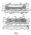
- Neck finish 10 of a bottle 11is partially shown in fig. 1.
- Neck finish 10includes an annular wall 12 defining there through cylindrical opening 13 having a first end 14 and a second end.
- First end 14provides access to opening 13.
- An annular flange 17is provided at the first end of the annular wall and extends inwardly of the wall 12.
- the annular flangeextends inwardly at a slight outward angle from the plane of the first end as shown in Fig 3.
- Ratchet teeth 18Positioned adjacent to second end 16 is at least one set of annular ratchet teeth 18 to provide a tamper evident grip for the cap.
- Ratchet teeth 18may be positioned around the entire circumference of the second end or only a portion thereof. In one embodiment, it is preferred that the teeth of two different sets of teeth 18 be positioned in an opposing direction to prevent "backing off' the cap from the bottle.
- Ratchet teeth 18are adapted to co-operatively engage corresponding teeth on a tamper evident ring positioned on the base of matching cap.
- a first annular ring flange 19 having a circumferential lip 21is positioned substantially adjacent to the plane in which the annular ratchet teeth 18 are provided.
- the annular ring flangeis particularly useful when using a low density plastic cap.
- a second annular ring flange 22 having a circumferential lip 23is provided proximate of the first end 14 of annular wall 11.
- Threads 24are helically spaced in contiguous relationship as shown in fig. 1.
- each thread 24extends less than 360° and more preferably less than 270° around the circumference of annular wall 11.
- neck finish 10is provided with a part line 25 (shown in dotted line) to facilitate removal of the neck from its mould.
- threads 24 that extend over a part line 25are discontinuous or interrupted and include terminating points 26a and 27a.
- the manufacture of neck finish 11is particularly well suited to standard blow moulding of milk containers by substitution of the neck finish mould conforming to the present invention.
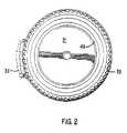
- cap 30is made from a low density polypropylene.
- Cap 30comprises a closure member having a top 31 designed to cover the mouth or opening in a neck finish of a container such as neck finish 10 of the present invention.
- the closure memberis substantially circular and includes depending annular wall 32.
- Annular wall 32includes a tamper-evident band 34 around its other end.
- Tamper-evident band 34includes a pull tab 36 which may be upwardly or downwardly extending.
- Tamper evident band 34is preferably formed as a part of annular wall 32 with tear line 38 to permit tearing the band from the wall to allow removal of the cap from the neck finish.
- Tamper-evident band 34includes ratchet teeth 39 adapted to engage teeth on the neck finish of a container, as shown in Fig. 2.
- Band 34can include frangible elements breakably securing them to the annular wall as is well known in the art.
- Cap 30includes a first annular lip or ring flange 40 positioned on the annular wall adjacent tear line 38.
- a second annular lip or ring flange 41is positioned on annular wall 32 proximate of top 31.
- First and second annular ring flanges 40 and 41are preferably located and dimensioned to engage and co-operatively retain cap 30 on first and second ring flanges 21 and 23 of neck finish 10, respectively, when the cap is pushed onto the neck finish.
- Threads 43extend less than 360° and more preferably less than 270° and most preferably less than 90° around the inner surface of annular depending wall 32.
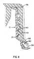
- annular valve 48Depending from top 31, is depending annular valve 48.
- Annular valve 48is spaced apart from annular depending wall 32 a distance which is represented by the difference in the radial distance from the outer edge of annular wall 12 at its first end 14 and centre of the opening 13 and the inner edge of annular wall 12 or flange 17 when used.
- Valve 48extends a point slightly less than the midpoint extent of threads 43.
- valve 48includes a taper 49 which permits initial engagement of the valve to the inner periphery of the neck finish opening upon engagement of cap 30 prior to the engagement of the first annular lips of the neck finish and cap respectively.
- Cap 30 when used in combination with neck finish 10 of the present inventionpermits both the placement and removal of the cap on the neck finish by pushing on or pulling off. By utilising at least ten threads, it is not necessary to screw the cap on or off the neck. However, by twisting the cap it is possible to obtain an even more secure closure when used by the ultimate consumer, while at the same time providing a leak proof container at the capping station without the necessity of so twisting.
- cap 130 in Figure 4includes only one annular lip or ring flange 140.
- the use of only one annular ring flangeprovides substantially the same closure sealing as two, but eliminates the need for extensive neck finish modification where the moulds are produced by separate manufacturers by eliminating the spacing requirement between the two annular ring flanges.
Landscapes
- Engineering & Computer Science (AREA)
- Mechanical Engineering (AREA)
- Ceramic Engineering (AREA)
- Closures For Containers (AREA)
Description
Claims (17)
- In combination, a cap (30) and a container (11), wherein
the container comprises:-and the cap (30) is snap-or screw-on, screw-off and tamper evident and comprises:-a neck finish (10) having an annular wall (12) with an outer surfaceand an inner surface defining a cylindrical opening (13) therethrough;at least one set of ratchet teeth (18) positioned around a portion of theouter wall surface at one end of the wall (12);
and,multiple start threads (24) helically spaced and positioned on the outerwall surface between the other wall end (14) and the ratchet teeth (18);the cap threads (43) being adapted to engage the neck finish threads (24)either by screw fit or direct compressive forcea closure member having a top (31) with a substantially circularperiphery to cover the neck finish (10) and an annular wall (32) dependingfrom the periphery of the top (31) and including an internal surface;a removable tamper-evident band (34) circumferentially positionedaround the depending annular wall (32) opposite from the top (31), the tamperevident band (34) including at least one means (39) to engage the ratchetteeth (18);
and,multiple start threads (43) helically spaced and positioned on theinternal wall surface to engage at least some of the threads (24) on the neckfinish (10), the threads (43) extending from above the tamper evident band (34), toproximate the closure member top (31),
characterised in thatthe neck finish (10) has at least ten threads (24) and a first annular ringflange (19) on and extending substantially around the wall outersurface between the threads (24) and the set of ratchet teeth (18);the tamper-evident cap (30) has at least 10 threads (43), a first annularring flange (40) positioned around the internal wall surface adjacentthe tamper evident band (34);the neck first annular ring flange (19) is located and dimensioned toengage and co-operate with the cap first annular ring flange (40) to retainthe cap (30) on the neck finish (10) when the cap (30) is engaged thereon. - The combination of claim 1and further characterised in that the neckfinish (10) includes a second annular ring flange (22) positioned between theother end (14) of the annular wall (12) and the threads (24) and the cap (30)includes a second annular ring flange (41) positioned between the top (31) andthe threads (43); the neck second annular ring flange (22) being located anddimensioned to engage and co-operate with the cap second annular ring flange (41)to retain the cap (30) on the neck finish (10) when the cap (30) is engaged thereon.
- The combination of claim 1 or claim 2and further characterised in thateach annular neck ring flange (19, 22) includes a circumferential lip (21,23).
- The combination of any of claims 1 to 3and further characterised in thatthe cap threads (43) are equal in number and at the same helical angle to theneck threads (24).
- The combination of any of claims 1 to 4and further characterised in thateach helical thread (24, 43) extends for less than 180°, preferably less than90°, around the neck outer wall surface or the cap internal wall surface.
- The combination of any of claims 1 to 5and further characterised in thatthe neck annular wall (12) has one or more moulding part lines (25) and thethreads (24) are discontinuous at the part line or lines.
- The combination of any of claims 1 to 6and further characterised in thatthe cap (30) is formed of low density plastic; for example polypropylene.
- A container comprising:-characterised in thata neck finish (10) having an annular wall (12) with an outer surface and aninner surface defining a cylindrical opening (13) there through;at least one set of ratchet teeth (18) positioned around a portion of the outerwall surface at one end of the wall;
and,multiple start threads (24) helically spaced and positioned on the outer wallsurface between the other wall end and the ratchet teeth;and for use with a given snap-or screw-on, screw-off and tamper evident capcomprising:-a closure member having a top (31) with a substantially circular periphery tocover the neck finish and an annular wall (32) depending from the peripheryof the top and including an internal surface;a removable tamper-evident band (34) circumferentially positioned around thedepending annular wall opposite from the cover, the tamper evident bandincluding at least one means (39) to engage the ratchet teeth;
and,multiple start threads (43) helically spaced and positioned on the internal wallsurface to engage at least some of the threads on the neck finish, the threadsextending from above the tamper evident band to proximate the closuremember top;the cap threads (43) being adapted to engage the neck finish threads (24)either by screw fit or direct compressive forcethe neck finish (10) has at least ten threads (24) and a first annular ring flange(19) on and extending substantially around the wall outer surface between thethreads (24) and the set of ratchet teeth (18) and is for use with a given tamper-evidentcap (30) having at least 10 threads (43) and a first annular ring flange(40) positioned around the internal wall surface adjacent the tamper evidentband (34);
andthe neck first annular ring flange (19) is located and dimensioned to engage andco-operate in use with the cap first annular ring flange (40) to retain the cap (30) on theneck finish (10) when the cap (30) is engaged thereon. - A container as claimed in claim 8and further characterised in that the neckfinish (10) includes a second annular ring flange (22) positioned between the other end (14) of the annular wall (12) and the threads (24) and is for use witha given cap (30) including a second annular ring flange (41) positionedbetween the top (31) and the threads (43); the neck second annular ring flange (22)being located and dimensioned to engage and co-operate in use with the capsecond annular ring flange (41) to retain the cap (30) on the neck finish when the cap (30) isengaged thereon.
- A container as claimed in claim 8 or claim 9and further characterised inthat each neck annular ring flange (19, 22) includes a circumferential lip (21,23).
- A container as claimed in any claims 8 to 10and further characterised inthat each helical thread (24) extends for less than 180°, preferably less than90°, around the neck outer wall surface.
- A container as claimed in any claims 8 to 11and further characterised inthat the neck annular wall (12) has one or more moulding part lines (25) andthe threads (24) are discontinuous at the part line or lines.
- A snap-or screw-on, screw-off and tamper evident cap comprising:-and for use with a given container comprising:-a closure member having a top (31) with a substantially circular periphery tocover a neck finish (10) of a container and an annular wall (32) depending from the peripheryof the top and including an internal surface;a removable tamper-evident band (34) circumferentially positioned around thedepending annular wall (32) opposite from the top (31), the tamper evident band (34)including at least one means (39) to engage ratchet teeth (18) on the neck finish (10);
and,multiple start threads (43) helically spaced and positioned on the internal wallsurface to engage at least some of threads (24) on the neck finish (10), the threads (43)extending from above the tamper evident band (34) to proximate the closuremember top (31);characterised in thatthe neck finish (10) having an annular wall (12) with an outer surface and aninner surface defining a cylindrical opening (13) there through;at least one set of the ratchet teeth (18) positioned around a portion of the outerwall surface at one end of the wall;
and,the threads (24) being multiple start threads (24) helically spaced and positioned on the outer wallsurface between the other wall end (14) and the ratchet teeth (18);the cap threads (43) being adapted to engage the neck finish threads (24)either by screw fit or direct compressive force
the tamper-evident cap (30) has at least 10 threads (43) and a first annular ringflange (40) positioned around the internal wall surface adjacent the tamperevident band (34); and is for use with a given container comprising the neckfinish (10) having at least ten threads (24) and a first annular ring flange (19)on and extending substantially around the wall outer surface between thethreads (24) and the set of ratchet teeth (18) and the cap first annular ring flange (46) islocated and dimensioned to engage and co-operate in use with neck firstannular ring flange (19) to retain the cap (30) on the neck finish (10) when the cap (30) isengaged thereon. - A cap as claimed in claim 13and further characterised in that the cap (30)includes a second annular ring flange (41) positioned between the top (31) andthe threads (43); and is for use with a given neck finish (10) including asecond annular ring flange (22) positioned between the other end (14) of theannular wall (12) and the threads (24), the cap second annular ring flange (41)being located and dimensioned to engage and co-operate in use with the necksecond annular ring flange (22) to retain the cap (30) on the neck finish (10) when the cap (30) isengaged thereon.
- A cap as claimed in claim 13 or claim 14and further characterised in thatthe cap threads (43) are equal in number and at the same helical angle to theneck threads (24) of a given container neck finish (10).
- A cap as claimed in any of claims 13 to 15and further characterised in thateach helical cap thread (43) extends for less than 180°, preferably less than90°, around the cap internal wall surface.
- The combination of any of claims 13 to 16and further characterised in thatthe cap (30) is formed of low density plastic; for example polypropylene.
Applications Claiming Priority (3)
| Application Number | Priority Date | Filing Date | Title |
|---|---|---|---|
| US08430019US5553727C1 (en) | 1995-04-27 | 1995-04-27 | Tamper-evident cap and neck finish |
| US430019 | 1995-04-27 | ||
| PCT/US1996/005835WO1996033921A1 (en) | 1995-04-27 | 1996-04-26 | Tamper-evident cap and neck finish |
Publications (2)
| Publication Number | Publication Date |
|---|---|
| EP0824466A1 EP0824466A1 (en) | 1998-02-25 |
| EP0824466B1true EP0824466B1 (en) | 2001-11-07 |
Family
ID=23705743
Family Applications (1)
| Application Number | Title | Priority Date | Filing Date |
|---|---|---|---|
| EP96913190AExpired - LifetimeEP0824466B1 (en) | 1995-04-27 | 1996-04-26 | Tamper-evident cap and neck finish |
Country Status (5)
| Country | Link |
|---|---|
| US (1) | US5553727C1 (en) |
| EP (1) | EP0824466B1 (en) |
| AU (1) | AU5578296A (en) |
| DE (1) | DE69616775D1 (en) |
| WO (1) | WO1996033921A1 (en) |
Families Citing this family (43)
| Publication number | Priority date | Publication date | Assignee | Title |
|---|---|---|---|---|
| US5775528A (en)* | 1995-08-21 | 1998-07-07 | Superseal Corporation | Snap-on/screw-off cap and neck configuration |
| US6073809A (en) | 1996-02-15 | 2000-06-13 | International Plastics And Equipment Corporation | Snap-on tamper evident closure with push-pull pour spout |
| GB2311285A (en)* | 1996-03-22 | 1997-09-24 | Beeson & Sons Ltd | Snap-on, twist-off container closure assemblies |
| US5862953A (en) | 1996-04-16 | 1999-01-26 | International Plastics And Equipment Corporation | Tamper evident push-pull closure with pour spout |
| US6116440A (en)* | 1996-11-01 | 2000-09-12 | Colgate - Palmolive Company | Resealable thermoformed container |
| US5827471A (en)* | 1997-03-06 | 1998-10-27 | Bomatic, Inc. | Blow molded container with improved neck with locking teeth and method for forming same |
| US5860545A (en)* | 1997-04-17 | 1999-01-19 | The Procter & Gamble Company | Plastic bottle closure with single relief recess proximate to the lower peripheral edge of said closure |
| USD415962S (en) | 1997-05-23 | 1999-11-02 | Jorge Alberto Lopez Garcia | Cap |
| MXPA00004145A (en) | 1997-10-30 | 2003-08-01 | Internat Plastics And Equipmen | Tortilla counter-stacker whit ballistic stacking. |
| US5947309A (en)* | 1998-03-09 | 1999-09-07 | Premium Plastics, Inc. | Container-closure combination with improved sealing feature |
| DE29807759U1 (en)* | 1998-04-29 | 1998-07-16 | Georg Menshen GmbH & Co KG, 57413 Finnentrop | Multi-thread screw arrangement |
| US6386380B1 (en) | 1999-11-16 | 2002-05-14 | Rexam Medical Packaging Inc. | Neck finish for a container and mold for forming the container |
| AU2001233092A1 (en) | 2000-01-29 | 2001-08-07 | Portola Packaging, Inc. | Threaded tamper-evident closure and neck finish for such a closure |
| WO2002090192A2 (en)* | 2001-05-04 | 2002-11-14 | Berry Plastics Corporation | Beverage container closure |
| WO2004014744A1 (en)* | 2002-08-09 | 2004-02-19 | Yoshino Kogyosho Co.,Ltd. | Mouth tube portion of synthetic resin bottle body |
| US7097790B2 (en)* | 2003-09-24 | 2006-08-29 | Berry Plastics Corporation | Method of producing a container closure |
| US7007817B2 (en)* | 2003-09-24 | 2006-03-07 | Berry Plastics Corporation | Container closure |
| US20050263476A1 (en)* | 2004-05-25 | 2005-12-01 | Cks Packaging, Inc. | Finish for injection blow molded container |
| US7694835B1 (en) | 2005-01-04 | 2010-04-13 | Rexam Closures And Containers Inc. | Drafted neck finish having angled thread face and closure package |
| US20070034590A1 (en)* | 2005-08-04 | 2007-02-15 | Hidding Douglas J | Bottle with retained ring finish feature |
| US8109396B1 (en) | 2006-03-31 | 2012-02-07 | Rexam Healthcare Packaging Inc. | Slide rails and friction surfaces for closure |
| US7735664B1 (en)* | 2006-04-18 | 2010-06-15 | Portola Packaging, Inc. | Tapered thread structure |
| JP4757122B2 (en)* | 2006-07-07 | 2011-08-24 | ヱスビー食品株式会社 | Cap locking device |
| US7891510B2 (en)* | 2006-12-26 | 2011-02-22 | Abbott Laboratories | Container closure assembly |
| US8056744B2 (en)* | 2007-01-12 | 2011-11-15 | Phoenix Closures, Inc. | Closure with ring ribs |
| FR2916741B1 (en)* | 2007-05-29 | 2009-08-28 | Airsec Soc Par Actions Simplif | CHILD SAFETY CLOSURE DEVICE WITH A SCREW AND A FIRST-OPEN WINDOW RING |
| US20110174761A1 (en)* | 2008-05-19 | 2011-07-21 | Omega Cap Solutions, LLC | Visual tamper-evident conical screw cap and neck finish |
| US20090283492A1 (en)* | 2008-05-19 | 2009-11-19 | Omega Cap Solutions Llc | Visual Tamper-Evident Conical Screw Cap and Neck Finish |
| US8857636B2 (en)* | 2009-11-12 | 2014-10-14 | John Lewis Sullivan | Sectional container with a detachable base and lid cover |
| WO2012018994A2 (en) | 2010-08-04 | 2012-02-09 | Omega Cap Solutions Llc | Step twist zipped visual tamper-evident cap and neck finish |
| DE202010015932U1 (en)* | 2010-11-26 | 2011-02-03 | Azani, Adam | Device for storing and mixing substances |
| WO2013015006A1 (en)* | 2011-07-26 | 2013-01-31 | 東洋製罐株式会社 | Container superior in preventing dripping |
| USD732391S1 (en)* | 2012-02-10 | 2015-06-23 | Silgan Plastics Llc | Container with ribbed neck |
| US9120591B2 (en)* | 2013-11-12 | 2015-09-01 | Silgan Plastics Llc | Plastic container neck configured for use with a fitment |
| US9254941B2 (en)* | 2014-03-25 | 2016-02-09 | Basf Corporation | Resealable container and closure package |
| US10399728B2 (en) | 2014-05-13 | 2019-09-03 | Owens-Brockway Glass Container Inc. | Neck finish for a container |
| US9511907B2 (en)* | 2014-07-10 | 2016-12-06 | Scholle Ipn Corporation | Spout assembly for a flexible bag |
| DK3204307T3 (en)* | 2014-10-07 | 2022-01-03 | Stanpac Inc | INTERVENTIVE LID AND METHOD OF MANUFACTURE THEREOF |
| JP6985000B2 (en)* | 2016-07-06 | 2021-12-22 | 大日本印刷株式会社 | Sealed structure and packaging container |
| CA3144738A1 (en)* | 2017-03-17 | 2018-09-20 | Altium Packaging Lp | Container with crush resistant spout |
| DE102017209974A1 (en)* | 2017-06-13 | 2018-12-13 | Sachsen Guss GmbH | Casting method for producing a threaded body |
| WO2021156703A1 (en)* | 2020-02-06 | 2021-08-12 | Novembal Usa Inc. | Stopper having interrupted threads |
| US11780652B1 (en)* | 2022-03-29 | 2023-10-10 | Pretium Packaging, L.L.C. | Tapered closure and closure system |
Family Cites Families (18)
| Publication number | Priority date | Publication date | Assignee | Title |
|---|---|---|---|---|
| US4497765A (en)* | 1979-09-21 | 1985-02-05 | H-C Industries, Inc. | Process for making a closure |
| GB8305779D0 (en)* | 1983-03-02 | 1983-04-07 | Massmould Holdings Ltd | Container and cap |
| US4534480A (en)* | 1984-06-01 | 1985-08-13 | Sun Coast Plastics, Inc. | Tamper evident closure |
| US4561553A (en)* | 1985-01-22 | 1985-12-31 | Northern Engineering And Plastics Corp. | Snap on twist off tamper-proof closure for containers |
| US4625875A (en)* | 1985-02-04 | 1986-12-02 | Carr Joseph J | Tamper-evident closure |
| US4572387A (en)* | 1985-03-01 | 1986-02-25 | Sunbeam Plastics Corporation | Screw-type safety cap |
| GB2172273B (en)* | 1985-03-14 | 1988-12-21 | Bormioli Metalplast Spa | Plastic cap in two parts incorporating a breakable seal, for bottles in particular |
| FR2611184B1 (en)* | 1987-02-19 | 1989-05-26 | Rical Sa | WATERPROOF SEALING DEVICE FOR CONTAINERS CONTAINING PRODUCTS WHICH MUST BE KEEPED AWAY FROM OXYGEN |
| IT1224357B (en)* | 1988-04-13 | 1990-10-04 | Bormioli Metalplast Spa | ONE-PIECE CAPSULE WITH DEFORMABLE INVIOLABILITY CLAMP |
| US4938370B1 (en)* | 1989-04-26 | 2000-10-17 | Hc Ind | Tamper-indicating plastic closure |
| US5009323A (en)* | 1989-11-13 | 1991-04-23 | Sunbeam Plastics Corporation | Tamper indicating closure having a rotary seal |
| GB9005417D0 (en)* | 1990-03-10 | 1990-05-09 | Metal Box Plc | Screw closures for containers |
| AU653334B2 (en)* | 1990-04-06 | 1994-09-29 | Carnaudmetalbox Plc | Metal screw closures for packaging containers |
| US5213224A (en)* | 1990-08-09 | 1993-05-25 | Portola Packaging, Inc. | Snap-on, screw-off cap and container neck |
| US5190178A (en)* | 1990-08-09 | 1993-03-02 | Cap Snap Co | Snap-on, screw-off cap and container neck |
| US5267661A (en)* | 1990-08-09 | 1993-12-07 | Portola Packaging, Inc. | Snap-on, screw off cap and container neck |
| US5307945A (en)* | 1992-06-26 | 1994-05-03 | Hidding Walter E | Closure |
| US5307946A (en)* | 1993-03-24 | 1994-05-03 | Northern Engineering & Plastics, Corp. | Neck finish for a container and a matching registering multiple thread pattern in a flexible cap for engagement on neck said finish |
- 1995
- 1995-04-27USUS08430019patent/US5553727C1/ennot_activeExpired - Fee Related
- 1996
- 1996-04-26EPEP96913190Apatent/EP0824466B1/ennot_activeExpired - Lifetime
- 1996-04-26AUAU55782/96Apatent/AU5578296A/ennot_activeAbandoned
- 1996-04-26DEDE69616775Tpatent/DE69616775D1/ennot_activeExpired - Lifetime
- 1996-04-26WOPCT/US1996/005835patent/WO1996033921A1/enactiveIP Right Grant
Also Published As
| Publication number | Publication date |
|---|---|
| AU5578296A (en) | 1996-11-18 |
| DE69616775D1 (en) | 2001-12-13 |
| EP0824466A1 (en) | 1998-02-25 |
| WO1996033921A1 (en) | 1996-10-31 |
| US5553727C1 (en) | 2001-09-04 |
| US5553727A (en) | 1996-09-10 |
Similar Documents
| Publication | Publication Date | Title |
|---|---|---|
| EP0824466B1 (en) | Tamper-evident cap and neck finish | |
| US6439412B2 (en) | Snap-on, screw-off cap and container neck | |
| US5213224A (en) | Snap-on, screw-off cap and container neck | |
| US4436212A (en) | Tamper proof closure | |
| EP2917122B1 (en) | Container, closure, and package | |
| US4206851A (en) | Tamperproof closure | |
| US6059134A (en) | Snap-on screw-off closure for use in combination with a container | |
| EP1114781B1 (en) | Tamper restistant bottle cap | |
| US5190178A (en) | Snap-on, screw-off cap and container neck | |
| US20050252878A1 (en) | Tamper-evident package | |
| US5004112A (en) | Tamper-indicating plastic closure | |
| US7228979B2 (en) | Snap-on screw-off closure with retaining member for tamper-indicating band | |
| US5560504A (en) | Snap on pull off tamper indicating flexible cap and neck configuration | |
| US20090283492A1 (en) | Visual Tamper-Evident Conical Screw Cap and Neck Finish | |
| US5036991A (en) | Tamper evident-cap for containers | |
| US11267624B2 (en) | Two-piece cap | |
| US5630520A (en) | Tabs for container closures and container neck | |
| US11919687B2 (en) | Package, container, closure assembly, and closure components | |
| WO2001055000A1 (en) | Threaded tamper-evident closure and neck finish for such a closure | |
| CA2329286C (en) | Tamper resistant bottle cap and neck | |
| CA1185924A (en) | Tamper proof closure | |
| MXPA00000563A (en) | Closure with extended seal member |
Legal Events
| Date | Code | Title | Description |
|---|---|---|---|
| PUAI | Public reference made under article 153(3) epc to a published international application that has entered the european phase | Free format text:ORIGINAL CODE: 0009012 | |
| 17P | Request for examination filed | Effective date:19971107 | |
| AK | Designated contracting states | Kind code of ref document:A1 Designated state(s):CH DE DK ES FR GB IT LI NL | |
| RAP1 | Party data changed (applicant data changed or rights of an application transferred) | Owner name:CONSUMER CAP CORPORATION | |
| 17Q | First examination report despatched | Effective date:19980729 | |
| GRAG | Despatch of communication of intention to grant | Free format text:ORIGINAL CODE: EPIDOS AGRA | |
| GRAG | Despatch of communication of intention to grant | Free format text:ORIGINAL CODE: EPIDOS AGRA | |
| GRAH | Despatch of communication of intention to grant a patent | Free format text:ORIGINAL CODE: EPIDOS IGRA | |
| GRAH | Despatch of communication of intention to grant a patent | Free format text:ORIGINAL CODE: EPIDOS IGRA | |
| RAP1 | Party data changed (applicant data changed or rights of an application transferred) | Owner name:NORTHERN ENGINEERING AND PLASTICS CORPORATION | |
| GRAA | (expected) grant | Free format text:ORIGINAL CODE: 0009210 | |
| GRAH | Despatch of communication of intention to grant a patent | Free format text:ORIGINAL CODE: EPIDOS IGRA | |
| AK | Designated contracting states | Kind code of ref document:B1 Designated state(s):CH DE DK ES FR GB IT LI NL | |
| PG25 | Lapsed in a contracting state [announced via postgrant information from national office to epo] | Ref country code:NL Free format text:LAPSE BECAUSE OF FAILURE TO SUBMIT A TRANSLATION OF THE DESCRIPTION OR TO PAY THE FEE WITHIN THE PRESCRIBED TIME-LIMIT Effective date:20011107 Ref country code:LI Free format text:LAPSE BECAUSE OF FAILURE TO SUBMIT A TRANSLATION OF THE DESCRIPTION OR TO PAY THE FEE WITHIN THE PRESCRIBED TIME-LIMIT Effective date:20011107 Ref country code:IT Free format text:LAPSE BECAUSE OF FAILURE TO SUBMIT A TRANSLATION OF THE DESCRIPTION OR TO PAY THE FEE WITHIN THE PRESCRIBED TIME-LIMIT;WARNING: LAPSES OF ITALIAN PATENTS WITH EFFECTIVE DATE BEFORE 2007 MAY HAVE OCCURRED AT ANY TIME BEFORE 2007. THE CORRECT EFFECTIVE DATE MAY BE DIFFERENT FROM THE ONE RECORDED. Effective date:20011107 Ref country code:FR Free format text:LAPSE BECAUSE OF FAILURE TO SUBMIT A TRANSLATION OF THE DESCRIPTION OR TO PAY THE FEE WITHIN THE PRESCRIBED TIME-LIMIT Effective date:20011107 Ref country code:CH Free format text:LAPSE BECAUSE OF FAILURE TO SUBMIT A TRANSLATION OF THE DESCRIPTION OR TO PAY THE FEE WITHIN THE PRESCRIBED TIME-LIMIT Effective date:20011107 | |
| REG | Reference to a national code | Ref country code:CH Ref legal event code:EP | |
| REF | Corresponds to: | Ref document number:69616775 Country of ref document:DE Date of ref document:20011213 | |
| REG | Reference to a national code | Ref country code:GB Ref legal event code:IF02 | |
| PG25 | Lapsed in a contracting state [announced via postgrant information from national office to epo] | Ref country code:DK Free format text:LAPSE BECAUSE OF FAILURE TO SUBMIT A TRANSLATION OF THE DESCRIPTION OR TO PAY THE FEE WITHIN THE PRESCRIBED TIME-LIMIT Effective date:20020207 | |
| PG25 | Lapsed in a contracting state [announced via postgrant information from national office to epo] | Ref country code:DE Free format text:LAPSE BECAUSE OF FAILURE TO SUBMIT A TRANSLATION OF THE DESCRIPTION OR TO PAY THE FEE WITHIN THE PRESCRIBED TIME-LIMIT Effective date:20020208 | |
| NLV1 | Nl: lapsed or annulled due to failure to fulfill the requirements of art. 29p and 29m of the patents act | ||
| REG | Reference to a national code | Ref country code:CH Ref legal event code:PL | |
| PG25 | Lapsed in a contracting state [announced via postgrant information from national office to epo] | Ref country code:ES Free format text:LAPSE BECAUSE OF FAILURE TO SUBMIT A TRANSLATION OF THE DESCRIPTION OR TO PAY THE FEE WITHIN THE PRESCRIBED TIME-LIMIT Effective date:20020530 | |
| EN | Fr: translation not filed | ||
| PLBE | No opposition filed within time limit | Free format text:ORIGINAL CODE: 0009261 | |
| STAA | Information on the status of an ep patent application or granted ep patent | Free format text:STATUS: NO OPPOSITION FILED WITHIN TIME LIMIT | |
| 26N | No opposition filed | ||
| PGFP | Annual fee paid to national office [announced via postgrant information from national office to epo] | Ref country code:GB Payment date:20060424 Year of fee payment:11 | |
| GBPC | Gb: european patent ceased through non-payment of renewal fee | Effective date:20070426 | |
| PG25 | Lapsed in a contracting state [announced via postgrant information from national office to epo] | Ref country code:GB Free format text:LAPSE BECAUSE OF NON-PAYMENT OF DUE FEES Effective date:20070426 |