EP0821980A1 - Catheter assembly - Google Patents
Catheter assemblyDownload PDFInfo
- Publication number
- EP0821980A1 EP0821980A1EP97113219AEP97113219AEP0821980A1EP 0821980 A1EP0821980 A1EP 0821980A1EP 97113219 AEP97113219 AEP 97113219AEP 97113219 AEP97113219 AEP 97113219AEP 0821980 A1EP0821980 A1EP 0821980A1
- Authority
- EP
- European Patent Office
- Prior art keywords
- catheter
- hub
- wire
- distal end
- sheath
- Prior art date
- Legal status (The legal status is an assumption and is not a legal conclusion. Google has not performed a legal analysis and makes no representation as to the accuracy of the status listed.)
- Granted
Links
- 230000000249desinfective effectEffects0.000claimsdescription3
- 210000003462veinAnatomy0.000description8
- 229920001971elastomerPolymers0.000description7
- 239000008280bloodSubstances0.000description6
- 210000004369bloodAnatomy0.000description6
- -1generallySubstances0.000description6
- 239000000463materialSubstances0.000description4
- 239000004743PolypropyleneSubstances0.000description3
- 238000005452bendingMethods0.000description3
- 210000004204blood vesselAnatomy0.000description3
- 238000003780insertionMethods0.000description3
- 230000037431insertionEffects0.000description3
- 229920001155polypropylenePolymers0.000description3
- 229920003002synthetic resinPolymers0.000description3
- 239000000057synthetic resinSubstances0.000description3
- 239000004698PolyethyleneSubstances0.000description2
- 239000003146anticoagulant agentSubstances0.000description2
- 239000003814drugSubstances0.000description2
- 238000000034methodMethods0.000description2
- 229920000573polyethylenePolymers0.000description2
- 229920002635polyurethanePolymers0.000description2
- 239000004814polyurethaneSubstances0.000description2
- 229920000915polyvinyl chloridePolymers0.000description2
- 239000004800polyvinyl chlorideSubstances0.000description2
- 241000894006BacteriaSpecies0.000description1
- 208000035049Blood-Borne InfectionsDiseases0.000description1
- 239000003242anti bacterial agentSubstances0.000description1
- 229940088710antibiotic agentDrugs0.000description1
- 229940127090anticoagulant agentDrugs0.000description1
- 229960004676antithrombotic agentDrugs0.000description1
- 210000001367arteryAnatomy0.000description1
- 239000003795chemical substances by applicationSubstances0.000description1
- 238000011109contaminationMethods0.000description1
- 238000007796conventional methodMethods0.000description1
- 229940079593drugDrugs0.000description1
- 230000000694effectsEffects0.000description1
- 239000012530fluidSubstances0.000description1
- 239000007788liquidSubstances0.000description1
- 238000004519manufacturing processMethods0.000description1
- 239000002184metalSubstances0.000description1
- 230000035515penetrationEffects0.000description1
- 229920000728polyesterPolymers0.000description1
- 239000007779soft materialSubstances0.000description1
Images


Classifications
- A—HUMAN NECESSITIES
- A61—MEDICAL OR VETERINARY SCIENCE; HYGIENE
- A61M—DEVICES FOR INTRODUCING MEDIA INTO, OR ONTO, THE BODY; DEVICES FOR TRANSDUCING BODY MEDIA OR FOR TAKING MEDIA FROM THE BODY; DEVICES FOR PRODUCING OR ENDING SLEEP OR STUPOR
- A61M25/00—Catheters; Hollow probes
- A61M25/01—Introducing, guiding, advancing, emplacing or holding catheters
- A61M25/06—Body-piercing guide needles or the like
- A61M25/0612—Devices for protecting the needle; Devices to help insertion of the needle, e.g. wings or holders
- A61M25/0637—Butterfly or winged devices, e.g. for facilitating handling or for attachment to the skin
- A—HUMAN NECESSITIES
- A61—MEDICAL OR VETERINARY SCIENCE; HYGIENE
- A61M—DEVICES FOR INTRODUCING MEDIA INTO, OR ONTO, THE BODY; DEVICES FOR TRANSDUCING BODY MEDIA OR FOR TAKING MEDIA FROM THE BODY; DEVICES FOR PRODUCING OR ENDING SLEEP OR STUPOR
- A61M25/00—Catheters; Hollow probes
- A61M25/01—Introducing, guiding, advancing, emplacing or holding catheters
- A61M25/06—Body-piercing guide needles or the like
- A61M25/0612—Devices for protecting the needle; Devices to help insertion of the needle, e.g. wings or holders
- A61M25/0618—Devices for protecting the needle; Devices to help insertion of the needle, e.g. wings or holders having means for protecting only the distal tip of the needle, e.g. a needle guard
Definitions
- the present inventionrelates to a catheter assembly capable of sanitarily and safety inserting catheter into a desired position in a human body.
- a catheter assemblyis used for introducing a cannula made of a synthetic resin into veins, arteries or a coelom of a patient and injecting a liquid medicine or removing a fluid.
- a catheteris inserted into, for example, a vein
- a piercing needlehaving an inner diameter larger than an outer diameter of a catheter is first pierced into a vein.
- a catheteris then guided to a desired position of the vein through a bore (lumen) of the piercing needle and, thereafter, only the catheter is left in the vain by removing the piercing needle from the vein.
- the catheter assemblyis comprised of a cannula, an inserter for slidably holding the cannula and a hub structure attached to a proximal end of the cannula, and is characterized in that a sheath is attached to the hub structure and surrounds the cannula, and the inserter is provided with a sheath stripping means and sheath longing members.
- the catheter assemblyis comprised of a cannula, an inserter for slidably holding the cannula and a hub structure attached to a proximal end of the cannula,and characterized in that a long accomodating tube for accomodating a needle (long piercing member) is provided therein.
- the cathetercan be inserted into a blood vessel by pushing it if the rigidity of the sheath is increased, the stripping resistance of the sheath is also increased.
- the rigidity of the sheathis weakened, the sheath cannot be inserted by pushing it since kinking or bending is caused in the sheath.
- the present inventionhas been developed in view of the above-described situation and it is an object of the present invention to provide a catheter assembly capable of sanitarily and safety inserting a catheter into a desired position in a human body by pushing it. Further, it is an object of the present invention to provide a catheter assembly capable of safely disposing of a piercing needle which has been removed after inserting a catheter.
- the inventorshave found, as a result of an intensive study, that problem of kinking or bending of a catheter is resolved by covering a periphery of a tubular member in which the catheter is inserted with the sheath that is provided around the catheter.
- a catheter assemblywith a long accommodating tube capable of accommodating not only a piercing needle but also a wire.
- the catheter assemblyincludes a catheter, a wing member, a tubular member, a sheath, a wire, a wire hub and a piercing member, the catheter having a lumen extending from a proximal end to a distal end and a hub provided at the proximal end thereof.
- the wing memberhas a support channel for slidably accommodating and supporting the catheter.
- the tubular memberis fixed to a proximal end of the support channel of the wing member and the catheter is slidably inserted therein.
- the sheathhas a slit or a weakened portion extending in a longitudinal direction from a distal end to a proximal end and is fixed to the hub coaxially with the catheter.
- the sheathslidably covers around the catheter and a periphery of the tubular member.
- the piercing memberincludes a piercing needle provided at a distal end of the catheter, a wire whose distal end is connected to a proximal end of the piercing needle and which extends beyound the hub, and a wire hub fixed to a proximal end of the wire.
- the piercing memberis slidably inserted through the lumen of the catheter and the distal end thereof is disposed to extend beyond the distal end of the catheter.
- a sheath stripping membercan be provided coutiguously to the proximal end of the support channel and on the periphery of the tubular member.
- the sheath stripping memberis constituted such that the outer diameter gradually increase toward the distal end and the distal end thereof is larger than the inner diameter of the sheath.
- an adjusting means for adjusting the direction of an edge face and the lie distance of the piercing needlemay be provided to the wire hub.
- a long accommodating tube for accommodating the piercing member thereinmay be provided between the hub of the catheter and the wire hub coaxially with the wire.
- the long accommodating tubeis preferably comprised of a connection member whose distal end is connectable to the catheter hub, a soft sleeve whose distal end is connected to a proximal end of the connection member and a sleeve protecting cylinder capable of accommodating the sleeve.
- a proximal end of the sleeveis preferably connected to the wire hub and the sleeve protecting cylinder is preferably connectable to the hub and the wire hub.
- the long accommodating tubemay include a wire disinfecting member provided around the wire.
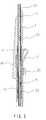
- a catheter assembly of the present inventionincludes a catheter 1 having a hub 11 at a proximal end thereof, a wing member 2 for supporting the catheter 1, a tubular member 3 fixed to the wing member 2 and having catheter 1 slidably inserted therein, a sheath 4 slidably covering a periphery of the tubular member 3 and the catheter 1 and fixed to the hub 11 coaxially with the catheter 1, and a piercing member 5 comprised of a piercing needle 51 provided at a distal end thereof, a wire 52 and a wire hub 53.
- the piercing member 5is slidably inserted in the catheter 1 and a distal end thereof is disposed to extended beyond a distal end of the catheter 1. Further, preferably, a long accommodating tube 6 is provided between the hub 11 and the wire hub 53.
- the catheter 1has a proximal end and a distal end, and is attached to a hub 11 at the proximal end thereof.
- the catheter 1has a lumen 12 extending from the proximal end to the distal end.
- the piercing needle 51 and the wire 52 of the piercing member 5are inserted into said lumen 12 as shown in Fig. 3.
- the catheter of the present inventionmay be made of any material so far as the material is suitable for introducing into an organism, polyfluoroethylene-polypropylene, polyurethane or the like is preferably adopted.
- the material of the cathetermay include a radiopaque agent or a drug such as an antithrombotic agent, an antibiotic agent and an anticoagulant agent or the like.
- the catheter 1is inserted in a support channel 21 of the wing member 2.
- the wing member 2is composed of the support channel 21 shaped like a tube for slidably accommodating and supporting the catheter 1 therein, a pair of wings 22 symmetrically provided about the support channel 21 and a sheath holding means 23 preferably provided on the proximal end side of the support channel 21 and approximately in the midpoint of the tubular member 3.
- the sheath holding means 23is not always necessary, if a slit 41 in the longitudinal direction is formed in the sheath 4, the sheath holding means 23 prevents the slit 41 of the sheath 4 from opening before the sheath is separated from the catheter 1.
- the proximal end side of the support channel 21is preferably inclined with respect to the skin such that it is easy for the piercing needle to pierce the skin.
- the angle of inclination thereofis normally between 15° and 45°.
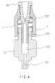
- the tubular member 3is fixed to the proximal end portion of the support channel 21 of the wing member 2. As shown in Fig. 2 and Fig. 3, the catheter 1 is slidably inserted in the tubular member 3 and the sheath 4 covers the tubular member 3.
- the tubular member 3is generally made of a metal or hard synthetic resin.
- the outer sheath 4is separated from the inner catheter 1 at the tubular member 3 and then covers the tubular member 3.
- the sheath 4is stripped from the tubular member 3 after the tubular member 3 separates the sheath 4 from the catheter 1. Therefore, in the stripping operation the catheter 1 can be prevented from being exposed and the stripping resistance of the sheath 4 does not directly act on the catheter 1.
- a sheath stripping member 31may be provided coutiguously to the proximal end of the support channel 21 and on a periphery of the tubular member 3.
- the sheath stripping member 31is constituted such that an outer diameter thereof gradually increases and an outer diameter of the distal end thereof becomes larger than an inner diameter of the sheath 4.
- the outer diameter of the sheath stripping member 31may have a size such that the sheath 4 can be split along the slit 41 or a weakened portion (not illustrated).
- the sheath 4is a tubular member having the slit 41 or a weakened portion in the longitudinal direction from the distal end to the proximal end, and the catheter 1 is slidably inserted therein.
- the proximal end of the sheath 4is fixed to the hub 11 coaxially with the catheter 1. Further, the distal end side portion of the sheath 4 slidably covers around the tubular member 3 and is separated from the catheter 1 inserted in the sheath 4 at the proximal end of the tubular member 3.
- the material for making the sheath 4is not particularly limited so far as long as it is a soft material, generally, polyethylene, polypropylene, polyurethane, soft polyvinyl chloride, polyfluoroethylene-propylene or the like is preferably adopted.
- the piercing member 5is inserted in the lumen 12 of the catheter 1.
- the piercing member 5includes the piercing needle 51 provided at the distal end thereof, wire 52 whose distal end is connected to the proximal end of the piercing needle 51 and which extends the hub 11, and wire hub 53 fixed to the proximal end of the wire 52.
- the piercing member 5is slidably inserted in the lumen 12 of the catheter 1 and the distal end of the piercing needle 51 is disposed to extend beyond the distal end of the catheter 1.
- a distance d(refer to Fig. 2) between the distal end of the catheter 1 and an edge face of the piercing needle 51 is referred to as the "lie distance".
- a suitable lie distanceis to be provided in order to pierce and insert the catheter 1 into a human body together with the piercing needle 51.
- an adjusting means 7 for adjusting the direction of the edge face and the lie distance dmay be preferably provided to the wire hub 53 of the catheter assembly according to the present invention as shown by Fig. 4.
- a distal end portion 531 shaped like a tube in which the wire 52 can be rotably insertedis preferably provided on the wire hub 53.
- the adjusting means 7is comprised of a female screw member 71 which is rotatably attached to the outer periphery of the wire hub 53 and a male screw member 72 which can be screwed into said female screw member 71.
- the male screw member 72has a longitudinal bore 721 and a longitudinal bore 722.
- the wire 52can be rotatably inserted in the bore 721 in the longitudinal direction.
- the bore 722is larger than the bore 721 and the distal end portion 531 of the wire hub 53 can be inserted therein. By inserting the distal end portion 531 of the wire hub 53 in the bore 722, the male screw member 72 and the wire hub 53 can be rotated together.
- numeral 532designates a hole for attaching the wire 52.
- adjusting means 7is provided to the wire hub 53, when the male screw member 72 is rotated, the wire hub 53 having the distal end portion 531 thereof inserted in bore 722 of the male screw member 72, is rotated along therewith. Therefore, the direction of the edge face of the piercing needle 51 can be adjusted. Also, after adjusting the direction of the edge face, when the male screw member 72 is fixed by hand and the female screw member 71 is rotated, the wire hub 53 is moved forward or backward, and thus, a suitable lie distance can be selected.
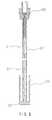
- a catheter assembly of the present inventionmay be preferably provided with a long accommodating tube 6, coaxially with the wire 52 and between the hub 11 and the wire hub 53 for accommodating a piercing member therein as illustrated in Figs. 5 through 8.
- the long accommodating tube 6 shown in Fig. 5is a tubular member having a proximal end portion 61 and a distal end portion 62.
- the proximal end portion 61 and the distal end portion 62are detachably connected to the wire hub 53 and the hub 11 respectively.
- the proximal end portion 61has a narrow portion 611 through which the wire 52 can pass but the piercing needle 51 cannot pass.
- the distal end portion 62is closed by a rubber plug 63 which is provided with a hole 631 (or a slit) through which the wire 62 and the piercing needle 51 can pass.
- the distance between the narrow portion 611 and the rubber plug 63is larger than the length of the piercing needle 51.
- a similar rubber plug 64may be provided contiguously to the narrow portion 611 of the proximal end portion 61 as necessary (as shown in Fig.5).
- a wire disinfecting member 65can be accommodated in the long accommodating tube 6 surrounding the wire 52 contiguously to the narrow portion 611 (or the rubber plug 64 if the rubber plug 64 is provided).
- the long accommodating tubemay also have a structure which can be accommodated with the wire 52 as shown in Figs. 7 and 8.
- a long accommodating tube 60is comprised of a connection member 66 whose distal end is connectable to the hub 11, a soft sleeve 67 whose distal end is connected to a proximal end of the connection member 66, and a sleeve protecting cylinder 68 capable of accommodating the sleeve 67 therein.
- the soft sleeve 67is constructed of a film or a sheet made of synthetic resin such as polyethylene, polypropylene, polyvinyl chloride, polyester or the like.
- the proximal end of the sleeve 67is connected to the wire hub 53 (or the adjus1ting means 7 if the wire hub 53 is provided with the adjusting means 7.
- the sleeve protecting cylinder 68can be connected to the hub 11 and the wire hub 53 (or the adjusting means 7 if the wire hub 53 is provided with the adjusting means .
- the connection member 66is provided with a rubber plug 69 which is formed with a hole 691 such that the piercing needle 51 cannot be retrogressed after passing through the hole 691.
- the length of the sleeve 67is determined such that the piercing needle 51 can pass through the rubber plug 69 when the sleeve 67 is extended.
- the sleeve protecting cylinder 68may be connectable to the connection member 66 and the wire hub 53 by fixing, screwing, fitting or the like, it is necessary that at least one of the connection member 66 and the wire hub 53 is detachable.
- the sleeve 67is accommodated in the sleeve protecting cylinder 68 in a state such that it is folded up in the longitudinal direction before accommodating the piercing member 5.
- the sleeve protecting cylinder 68is attached, for example, to the wire hub 53 as shown in Fig.
Landscapes
- Health & Medical Sciences (AREA)
- Life Sciences & Earth Sciences (AREA)
- Biophysics (AREA)
- Pulmonology (AREA)
- Engineering & Computer Science (AREA)
- Anesthesiology (AREA)
- Biomedical Technology (AREA)
- Heart & Thoracic Surgery (AREA)
- Hematology (AREA)
- Animal Behavior & Ethology (AREA)
- General Health & Medical Sciences (AREA)
- Public Health (AREA)
- Veterinary Medicine (AREA)
- Media Introduction/Drainage Providing Device (AREA)
Abstract
Description
Claims (6)
- A catheter assembly comprising:a catheter having a lumen extending ham a proximal end to a distalend thereof and having a hub provided at the proximal end thereof;a wing member having a support channel for slidably accommodatingand supporting the catheter therein;a tubular member fixed to a proximal end of the support channel of thewing member, said catheter being slidably inserted therein;a sheath having a slit or a weakened portion extending in a longitudinaldirection from a distal end to a proximal end thereof , said sheath slidablycovering the catheter and the tubular member and being fixed to said hubcoaxially with the catheter; anda piercing member slidably inserted through the lumen of the catheter , saidpiercing member including a piercing needle provided at a distal end thereof, awire having a distal end connected to a proximal end of the piercing needle andextending beyond said hub, and a wire hub fixed to a proximal end of said wire,wherein a distal end of the piercing needle extends beyond the distal end of thecatheter.
- The catheter assembly according to Claim 1, wherei a sheathstripping member is provided cautiguously to the proximal end of the supportchannel and on a periphery of the tubular member, said sheath stripping memberhaving an outer diameter thereof that is gradually increased in a direction of adistal end of said support channel, an outer diameter of a distal end of said sheathstripping member being larger than an inner diameter of the sheath.
- The catheter assembly according to Claim 1 or 2, wherein the wire hub is provided with an adjusting means for adjusting a direction of an edge face and alie distance of the piercing needle .
- The catheter assembly according to any one of Claims 1 through 3:
wherein a long accommodating tube for accommodating the piercingmember therein is provided between the hub and the wire hub coaxially with thewire. - The catheter assembly according to Claim 4, wherein the longaccommodating tube comprises a connection member having a distal enddetachably connected to said hub, an extendable soft sleeve having a distal endconnected to a proximal end of the connection member, and a sleeve protectingcylinder capable of accommodating said sleeve therein; and
wherein a proximal end of said sleeve is connected to said wire hub andsaid sleeve protecting cylinder is detachably connected to said hub and the wirehub. - The catheter assembly according to Claim 4, wherein the longaccommodating tube includes a wire disinfecting member provided around thewire.
Applications Claiming Priority (3)
| Application Number | Priority Date | Filing Date | Title |
|---|---|---|---|
| JP20441996AJP3324108B2 (en) | 1996-08-02 | 1996-08-02 | Catheter assembly |
| JP20441996 | 1996-08-02 | ||
| JP204419/96 | 1996-08-02 |
Publications (2)
| Publication Number | Publication Date |
|---|---|
| EP0821980A1true EP0821980A1 (en) | 1998-02-04 |
| EP0821980B1 EP0821980B1 (en) | 2003-04-16 |
Family
ID=16490237
Family Applications (1)
| Application Number | Title | Priority Date | Filing Date |
|---|---|---|---|
| EP97113219AExpired - LifetimeEP0821980B1 (en) | 1996-08-02 | 1997-07-31 | Catheter assembly |
Country Status (4)
| Country | Link |
|---|---|
| US (1) | US5902274A (en) |
| EP (1) | EP0821980B1 (en) |
| JP (1) | JP3324108B2 (en) |
| DE (1) | DE69720881T2 (en) |
Cited By (7)
| Publication number | Priority date | Publication date | Assignee | Title |
|---|---|---|---|---|
| WO1999016496A1 (en)* | 1997-09-30 | 1999-04-08 | Becton Dickinson And Company | Multiple sheath catheter using multiple stages and method of use |
| US6228062B1 (en) | 1998-09-15 | 2001-05-08 | Becton, Dickinson And Company | One piece lock for splittable sheath |
| EP2571562A4 (en)* | 2010-05-19 | 2015-05-06 | Tangent Medical Technologies Llc | Integrated vascular delivery system with safety needle |
| US9592366B2 (en) | 2009-08-14 | 2017-03-14 | The Regents Of The University Of Michigan | Integrated vascular delivery system |
| US10569057B2 (en) | 2010-05-19 | 2020-02-25 | Tangent Medical Technologies, Inc. | Integrated vascular delivery system |
| US10814107B2 (en) | 2014-02-04 | 2020-10-27 | Icu Medical, Inc. | Self-priming systems and methods |
| US10905858B2 (en) | 2010-05-19 | 2021-02-02 | Tangent Medical Technologies, Inc. | Safety needle system operable with a medical device |
Families Citing this family (33)
| Publication number | Priority date | Publication date | Assignee | Title |
|---|---|---|---|---|
| US6520933B1 (en) | 1998-04-21 | 2003-02-18 | Alsius Corporation | Central venous line cooling catheter having a spiral-shaped heat exchange member |
| US6419643B1 (en) | 1998-04-21 | 2002-07-16 | Alsius Corporation | Central venous catheter with heat exchange properties |
| US8128595B2 (en) | 1998-04-21 | 2012-03-06 | Zoll Circulation, Inc. | Method for a central venous line catheter having a temperature control system |
| US5961493A (en)* | 1998-06-03 | 1999-10-05 | Liu; Wen-Neng | Automatic safety infusion catheter needle |
| US6719724B1 (en) | 1999-02-19 | 2004-04-13 | Alsius Corporation | Central venous line catheter having multiple heat exchange elements and multiple infusion lumens |
| USD440304S1 (en) | 1999-10-27 | 2001-04-10 | Corvascular, Inc. | Direct fluid-delivery system |
| US6755842B2 (en)* | 2000-09-01 | 2004-06-29 | Angiolink Corporation | Advanced wound site management systems and methods |
| US8551134B2 (en)* | 2000-09-01 | 2013-10-08 | Medtronic Vascular, Inc. | Wound site management and wound closure device |
| US6572640B1 (en) | 2001-11-21 | 2003-06-03 | Alsius Corporation | Method and apparatus for cardiopulmonary bypass patient temperature control |
| EP1907042B1 (en) | 2005-07-06 | 2009-03-11 | Vascular Pathways Inc. | Intravenous catheter insertion device and method of use |
| EP2150304B1 (en) | 2007-05-07 | 2010-12-01 | Vascular Pathways Inc. | Intravenous catheter insertion and blood sample devices and method of use |
| DE202009013213U1 (en)* | 2009-10-01 | 2009-12-17 | B. Braun Melsungen Ag | catheter introducer |
| CA2818960C (en) | 2009-12-15 | 2018-11-13 | The Board Of Regents Of The University Of Nebraska | Sheath |
| US9872971B2 (en) | 2010-05-14 | 2018-01-23 | C. R. Bard, Inc. | Guidewire extension system for a catheter placement device |
| US8932258B2 (en) | 2010-05-14 | 2015-01-13 | C. R. Bard, Inc. | Catheter placement device and method |
| US10384039B2 (en) | 2010-05-14 | 2019-08-20 | C. R. Bard, Inc. | Catheter insertion device including top-mounted advancement components |
| US9950139B2 (en) | 2010-05-14 | 2018-04-24 | C. R. Bard, Inc. | Catheter placement device including guidewire and catheter control elements |
| US11925779B2 (en) | 2010-05-14 | 2024-03-12 | C. R. Bard, Inc. | Catheter insertion device including top-mounted advancement components |
| US8690833B2 (en) | 2011-01-31 | 2014-04-08 | Vascular Pathways, Inc. | Intravenous catheter and insertion device with reduced blood spatter |
| ES2835652T3 (en) | 2011-02-25 | 2021-06-22 | Bard Inc C R | Medical component insertion device including a retractable needle |
| USD903101S1 (en) | 2011-05-13 | 2020-11-24 | C. R. Bard, Inc. | Catheter |
| WO2014120741A1 (en) | 2013-01-30 | 2014-08-07 | Vascular Pathways, Inc. | Systems and methods for venipuncture and catheter placement |
| EP3777956B1 (en) | 2013-10-15 | 2024-06-12 | Radux Devices, LLC | Securing a medical device to a valve instrument |
| WO2016037127A1 (en) | 2014-09-05 | 2016-03-10 | C.R. Bard, Inc. | Catheter insertion device including retractable needle |
| USD903100S1 (en) | 2015-05-01 | 2020-11-24 | C. R. Bard, Inc. | Catheter placement device |
| CN113350614A (en) | 2015-05-15 | 2021-09-07 | C·R·巴德股份有限公司 | Catheter placement device including extendable needle safety feature |
| US10099037B2 (en) | 2015-09-15 | 2018-10-16 | Radux Devices, LLC | Sheath retainer devices, systems and methods |
| US10493262B2 (en) | 2016-09-12 | 2019-12-03 | C. R. Bard, Inc. | Blood control for a catheter insertion device |
| EP3585471B1 (en) | 2017-03-01 | 2025-01-01 | C. R. Bard, Inc. | Catheter insertion device |
| US10556094B2 (en) | 2017-03-15 | 2020-02-11 | Radux Devices, LLC | Interventional tool delivery devices, systems and methods |
| ES2980192T3 (en) | 2018-03-07 | 2024-09-30 | Bard Access Systems Inc | Guidewire advancement and blood reflux systems for a medical device insertion system |
| USD921884S1 (en) | 2018-07-27 | 2021-06-08 | Bard Access Systems, Inc. | Catheter insertion device |
| CA3151126A1 (en) | 2019-08-19 | 2021-02-25 | Becton, Dickinson And Company | Midline catheter placement device |
Citations (7)
| Publication number | Priority date | Publication date | Assignee | Title |
|---|---|---|---|---|
| US3769975A (en)* | 1971-11-26 | 1973-11-06 | Johnson & Johnson | Slit sleeve for preventing displacement in a catheter assembly |
| EP0008451A1 (en)* | 1978-08-21 | 1980-03-05 | Abbott Laboratories | Catheter placement assembly having axial and rotational alignment means |
| US4349022A (en)* | 1979-08-10 | 1982-09-14 | Soji Ishikawa | Medical needle assembly |
| EP0314470A2 (en)* | 1987-10-30 | 1989-05-03 | Menlo Care Inc. | Needle protector |
| US4840613A (en)* | 1988-04-27 | 1989-06-20 | Menlo Care, Inc. | Protective sheath for catheter assembly |
| GB2279570A (en)* | 1993-05-27 | 1995-01-11 | Kyung Jin Song | Vein needle set |
| US5501674A (en)* | 1994-03-07 | 1996-03-26 | Medrad, Inc. | Intravenous catheter with needle cover and blood collection tube |
Family Cites Families (7)
| Publication number | Priority date | Publication date | Assignee | Title |
|---|---|---|---|---|
| DE1025223B (en)* | 1954-10-11 | 1958-02-27 | Carl Sandmann Fa | Safety device for shut-off valves |
| GB976852A (en)* | 1962-12-11 | 1964-12-02 | Thompson Brothers Bilston Ltd | Valves or cocks |
| US4982760A (en)* | 1988-10-31 | 1991-01-08 | Flotec, Inc. | Three-way valve with radial seal |
| US5409461A (en)* | 1993-09-28 | 1995-04-25 | Becton Dickinson And Company | Catheter introducer assembly with needle shielding device |
| US5542930A (en)* | 1995-01-06 | 1996-08-06 | Schur; Israel | Catheter assembly |
| US5697914A (en)* | 1995-03-16 | 1997-12-16 | Becton Dickinson And Company | Control forward/flashback forward one hand introducer needle and catheter assembly |
| US5688249A (en)* | 1995-03-28 | 1997-11-18 | Johnson & Johnson Medical, Inc. | Telescoping members for catheter introducer assembly |
- 1996
- 1996-08-02JPJP20441996Apatent/JP3324108B2/ennot_activeExpired - Fee Related
- 1997
- 1997-07-31EPEP97113219Apatent/EP0821980B1/ennot_activeExpired - Lifetime
- 1997-07-31DEDE69720881Tpatent/DE69720881T2/ennot_activeExpired - Fee Related
- 1997-08-01USUS08/905,024patent/US5902274A/ennot_activeExpired - Fee Related
Patent Citations (8)
| Publication number | Priority date | Publication date | Assignee | Title |
|---|---|---|---|---|
| US3769975A (en)* | 1971-11-26 | 1973-11-06 | Johnson & Johnson | Slit sleeve for preventing displacement in a catheter assembly |
| EP0008451A1 (en)* | 1978-08-21 | 1980-03-05 | Abbott Laboratories | Catheter placement assembly having axial and rotational alignment means |
| US4349022A (en)* | 1979-08-10 | 1982-09-14 | Soji Ishikawa | Medical needle assembly |
| EP0314470A2 (en)* | 1987-10-30 | 1989-05-03 | Menlo Care Inc. | Needle protector |
| US4840613A (en)* | 1988-04-27 | 1989-06-20 | Menlo Care, Inc. | Protective sheath for catheter assembly |
| US4840613B1 (en)* | 1988-04-27 | 1993-07-27 | Menlo Care Inc | |
| GB2279570A (en)* | 1993-05-27 | 1995-01-11 | Kyung Jin Song | Vein needle set |
| US5501674A (en)* | 1994-03-07 | 1996-03-26 | Medrad, Inc. | Intravenous catheter with needle cover and blood collection tube |
Cited By (14)
| Publication number | Priority date | Publication date | Assignee | Title |
|---|---|---|---|---|
| WO1999016496A1 (en)* | 1997-09-30 | 1999-04-08 | Becton Dickinson And Company | Multiple sheath catheter using multiple stages and method of use |
| US6228062B1 (en) | 1998-09-15 | 2001-05-08 | Becton, Dickinson And Company | One piece lock for splittable sheath |
| WO2000015287A3 (en)* | 1998-09-15 | 2001-11-29 | Becton Dickinson Co | One piece lock for splittable sheath |
| US11577053B2 (en) | 2009-08-14 | 2023-02-14 | The Regents Of The University Of Michigan | Integrated vascular delivery system |
| US9592366B2 (en) | 2009-08-14 | 2017-03-14 | The Regents Of The University Of Michigan | Integrated vascular delivery system |
| US10668252B2 (en) | 2009-08-14 | 2020-06-02 | The Regents Of The University Of Michigan | Integrated vascular delivery system |
| US12370348B2 (en) | 2009-08-14 | 2025-07-29 | The Regents Of The University Of Michigan | Integrated vascular delivery system |
| US10569057B2 (en) | 2010-05-19 | 2020-02-25 | Tangent Medical Technologies, Inc. | Integrated vascular delivery system |
| US10905858B2 (en) | 2010-05-19 | 2021-02-02 | Tangent Medical Technologies, Inc. | Safety needle system operable with a medical device |
| EP2571562A4 (en)* | 2010-05-19 | 2015-05-06 | Tangent Medical Technologies Llc | Integrated vascular delivery system with safety needle |
| US11577052B2 (en) | 2010-05-19 | 2023-02-14 | Tangent Medical Technologies, Inc. | Integrated vascular delivery system |
| US12059538B2 (en) | 2010-05-19 | 2024-08-13 | Tangent Medical Technologies, Inc. | Safety needle system operable with a medical device |
| US10814107B2 (en) | 2014-02-04 | 2020-10-27 | Icu Medical, Inc. | Self-priming systems and methods |
| US11724071B2 (en) | 2014-02-04 | 2023-08-15 | Icu Medical, Inc. | Self-priming systems and methods |
Also Published As
| Publication number | Publication date |
|---|---|
| DE69720881T2 (en) | 2003-11-06 |
| DE69720881D1 (en) | 2003-05-22 |
| EP0821980B1 (en) | 2003-04-16 |
| US5902274A (en) | 1999-05-11 |
| JPH1043308A (en) | 1998-02-17 |
| JP3324108B2 (en) | 2002-09-17 |
Similar Documents
| Publication | Publication Date | Title |
|---|---|---|
| EP0821980B1 (en) | Catheter assembly | |
| US4068659A (en) | Catheter placement assembly | |
| EP0732118B1 (en) | Control forward introducer needle and catheter assembly | |
| US4068660A (en) | Catheter placement assembly improvement | |
| US5697914A (en) | Control forward/flashback forward one hand introducer needle and catheter assembly | |
| US4417886A (en) | Catheter introduction set | |
| US4412832A (en) | Peelable catheter introduction device | |
| US3633579A (en) | Catheter placement device and method | |
| KR100424964B1 (en) | Catheter device with interlocking continuous guard member for cannula protection | |
| EP1144041B1 (en) | Catheter introducer assembly with one piece lock for splittable sheath | |
| US6626869B1 (en) | Guide wire introducer | |
| US4224943A (en) | Cannula and method for bidirectional blood flow | |
| EP0093101A2 (en) | A device for introducing a catheter into a blood vessel | |
| JPH0747047B2 (en) | Needle shield device | |
| CA1114705A (en) | Cannula and method for bidirectional blood flow | |
| US4304231A (en) | Catheter with wire stylet | |
| EP0556618B1 (en) | Surgical dilator | |
| RU2161048C2 (en) | Needle tip protector | |
| MXPA96002222A (en) | Ag point protector | |
| EP4138976B1 (en) | Cannulators and methods thereof | |
| US20210268237A1 (en) | Introducer Tool And Methods Thereof |
Legal Events
| Date | Code | Title | Description |
|---|---|---|---|
| PUAI | Public reference made under article 153(3) epc to a published international application that has entered the european phase | Free format text:ORIGINAL CODE: 0009012 | |
| AK | Designated contracting states | Kind code of ref document:A1 Designated state(s):BE DE FR GB IT | |
| 17P | Request for examination filed | Effective date:19980716 | |
| AKX | Designation fees paid | Free format text:BE DE FR GB IT | |
| RBV | Designated contracting states (corrected) | Designated state(s):BE DE FR GB IT | |
| RAP1 | Party data changed (applicant data changed or rights of an application transferred) | Owner name:NIPRO CORPORATION | |
| GRAG | Despatch of communication of intention to grant | Free format text:ORIGINAL CODE: EPIDOS AGRA | |
| 17Q | First examination report despatched | Effective date:20020531 | |
| GRAG | Despatch of communication of intention to grant | Free format text:ORIGINAL CODE: EPIDOS AGRA | |
| GRAH | Despatch of communication of intention to grant a patent | Free format text:ORIGINAL CODE: EPIDOS IGRA | |
| GRAH | Despatch of communication of intention to grant a patent | Free format text:ORIGINAL CODE: EPIDOS IGRA | |
| GRAA | (expected) grant | Free format text:ORIGINAL CODE: 0009210 | |
| AK | Designated contracting states | Designated state(s):BE DE FR GB IT | |
| REG | Reference to a national code | Ref country code:GB Ref legal event code:FG4D | |
| REF | Corresponds to: | Ref document number:69720881 Country of ref document:DE Date of ref document:20030522 Kind code of ref document:P | |
| PGFP | Annual fee paid to national office [announced via postgrant information from national office to epo] | Ref country code:FR Payment date:20030711 Year of fee payment:7 | |
| PGFP | Annual fee paid to national office [announced via postgrant information from national office to epo] | Ref country code:GB Payment date:20030730 Year of fee payment:7 | |
| PGFP | Annual fee paid to national office [announced via postgrant information from national office to epo] | Ref country code:DE Payment date:20030807 Year of fee payment:7 | |
| PGFP | Annual fee paid to national office [announced via postgrant information from national office to epo] | Ref country code:BE Payment date:20031001 Year of fee payment:7 | |
| ET | Fr: translation filed | ||
| PLBE | No opposition filed within time limit | Free format text:ORIGINAL CODE: 0009261 | |
| STAA | Information on the status of an ep patent application or granted ep patent | Free format text:STATUS: NO OPPOSITION FILED WITHIN TIME LIMIT | |
| 26N | No opposition filed | Effective date:20040119 | |
| PG25 | Lapsed in a contracting state [announced via postgrant information from national office to epo] | Ref country code:GB Free format text:LAPSE BECAUSE OF NON-PAYMENT OF DUE FEES Effective date:20040731 Ref country code:BE Free format text:LAPSE BECAUSE OF NON-PAYMENT OF DUE FEES Effective date:20040731 | |
| BERE | Be: lapsed | Owner name:*NIPRO CORP. Effective date:20040731 | |
| PG25 | Lapsed in a contracting state [announced via postgrant information from national office to epo] | Ref country code:DE Free format text:LAPSE BECAUSE OF NON-PAYMENT OF DUE FEES Effective date:20050201 | |
| GBPC | Gb: european patent ceased through non-payment of renewal fee | Effective date:20040731 | |
| PG25 | Lapsed in a contracting state [announced via postgrant information from national office to epo] | Ref country code:FR Free format text:LAPSE BECAUSE OF NON-PAYMENT OF DUE FEES Effective date:20050429 | |
| REG | Reference to a national code | Ref country code:FR Ref legal event code:ST | |
| PG25 | Lapsed in a contracting state [announced via postgrant information from national office to epo] | Ref country code:IT Free format text:LAPSE BECAUSE OF NON-PAYMENT OF DUE FEES;WARNING: LAPSES OF ITALIAN PATENTS WITH EFFECTIVE DATE BEFORE 2007 MAY HAVE OCCURRED AT ANY TIME BEFORE 2007. THE CORRECT EFFECTIVE DATE MAY BE DIFFERENT FROM THE ONE RECORDED. Effective date:20050731 | |
| BERE | Be: lapsed | Owner name:*NIPRO CORP. Effective date:20040731 |