EP0817483A2 - Television device having text data processing function - Google Patents
Television device having text data processing functionDownload PDFInfo
- Publication number
- EP0817483A2 EP0817483A2EP97111327AEP97111327AEP0817483A2EP 0817483 A2EP0817483 A2EP 0817483A2EP 97111327 AEP97111327 AEP 97111327AEP 97111327 AEP97111327 AEP 97111327AEP 0817483 A2EP0817483 A2EP 0817483A2
- Authority
- EP
- European Patent Office
- Prior art keywords
- tuner
- channel
- signal
- text data
- text
- Prior art date
- Legal status (The legal status is an assumption and is not a legal conclusion. Google has not performed a legal analysis and makes no representation as to the accuracy of the status listed.)
- Granted
Links
Images


Classifications
- H—ELECTRICITY
- H04—ELECTRIC COMMUNICATION TECHNIQUE
- H04N—PICTORIAL COMMUNICATION, e.g. TELEVISION
- H04N5/00—Details of television systems
- H04N5/44—Receiver circuitry for the reception of television signals according to analogue transmission standards
- H04N5/445—Receiver circuitry for the reception of television signals according to analogue transmission standards for displaying additional information
- H04N5/45—Picture in picture, e.g. displaying simultaneously another television channel in a region of the screen
- H—ELECTRICITY
- H04—ELECTRIC COMMUNICATION TECHNIQUE
- H04N—PICTORIAL COMMUNICATION, e.g. TELEVISION
- H04N21/00—Selective content distribution, e.g. interactive television or video on demand [VOD]
- H04N21/40—Client devices specifically adapted for the reception of or interaction with content, e.g. set-top-box [STB]; Operations thereof
- H04N21/41—Structure of client; Structure of client peripherals
- H04N21/426—Internal components of the client ; Characteristics thereof
- H04N21/42607—Internal components of the client ; Characteristics thereof for processing the incoming bitstream
- H04N21/4263—Internal components of the client ; Characteristics thereof for processing the incoming bitstream involving specific tuning arrangements, e.g. two tuners
- H—ELECTRICITY
- H04—ELECTRIC COMMUNICATION TECHNIQUE
- H04N—PICTORIAL COMMUNICATION, e.g. TELEVISION
- H04N21/00—Selective content distribution, e.g. interactive television or video on demand [VOD]
- H04N21/40—Client devices specifically adapted for the reception of or interaction with content, e.g. set-top-box [STB]; Operations thereof
- H04N21/43—Processing of content or additional data, e.g. demultiplexing additional data from a digital video stream; Elementary client operations, e.g. monitoring of home network or synchronising decoder's clock; Client middleware
- H04N21/431—Generation of visual interfaces for content selection or interaction; Content or additional data rendering
- H04N21/4312—Generation of visual interfaces for content selection or interaction; Content or additional data rendering involving specific graphical features, e.g. screen layout, special fonts or colors, blinking icons, highlights or animations
- H04N21/4316—Generation of visual interfaces for content selection or interaction; Content or additional data rendering involving specific graphical features, e.g. screen layout, special fonts or colors, blinking icons, highlights or animations for displaying supplemental content in a region of the screen, e.g. an advertisement in a separate window
- H—ELECTRICITY
- H04—ELECTRIC COMMUNICATION TECHNIQUE
- H04N—PICTORIAL COMMUNICATION, e.g. TELEVISION
- H04N21/00—Selective content distribution, e.g. interactive television or video on demand [VOD]
- H04N21/40—Client devices specifically adapted for the reception of or interaction with content, e.g. set-top-box [STB]; Operations thereof
- H04N21/47—End-user applications
- H04N21/488—Data services, e.g. news ticker
- H—ELECTRICITY
- H04—ELECTRIC COMMUNICATION TECHNIQUE
- H04N—PICTORIAL COMMUNICATION, e.g. TELEVISION
- H04N7/00—Television systems
- H04N7/08—Systems for the simultaneous or sequential transmission of more than one television signal, e.g. additional information signals, the signals occupying wholly or partially the same frequency band, e.g. by time division
- H04N7/087—Systems for the simultaneous or sequential transmission of more than one television signal, e.g. additional information signals, the signals occupying wholly or partially the same frequency band, e.g. by time division with signal insertion during the vertical blanking interval only
- H04N7/088—Systems for the simultaneous or sequential transmission of more than one television signal, e.g. additional information signals, the signals occupying wholly or partially the same frequency band, e.g. by time division with signal insertion during the vertical blanking interval only the inserted signal being digital
- H04N7/0882—Systems for the simultaneous or sequential transmission of more than one television signal, e.g. additional information signals, the signals occupying wholly or partially the same frequency band, e.g. by time division with signal insertion during the vertical blanking interval only the inserted signal being digital for the transmission of character code signals, e.g. for teletext
- H—ELECTRICITY
- H04—ELECTRIC COMMUNICATION TECHNIQUE
- H04N—PICTORIAL COMMUNICATION, e.g. TELEVISION
- H04N5/00—Details of television systems
- H04N5/44—Receiver circuitry for the reception of television signals according to analogue transmission standards
- H04N5/445—Receiver circuitry for the reception of television signals according to analogue transmission standards for displaying additional information
Definitions
- This inventionrelates to a television device which has a text data processing function and a multiscreen display function and which can receive and display text data in addition to a television signal.
- the television device of the multiscreen systemcan display a first image which is compressed in the horizontal direction as a parent screen on one side of the wide screen and display another compressed image as a child screen on a space area on the other side of the wide screen.
- the display modeis known as PIP (Picture In Picture).
- the wide screencan be divided into right and left areas of the same size and images of different broadcasting programs can be simultaneously displayed on the right and left shared screens.
- the television device of double-screen systemhas two different tuners.
- a data broadcasting programfor transmitting text data multiplexed on the television signal.
- the text datais multiplexed in the vertical blanking period of the television signal.
- a normal television broadcasting program and a data broadcasting programare received, an image of the normal television broadcasting program is displayed on one of the shared screens, and an image of the text data of the data broadcasting program is displayed on the other shared screen.
- the double-screen systemcan be utilized in various configurations of display types. That is, there are provided a one-screen display mode in which a normal television broadcasting program is received by use of only the first tuner and the image is displayed on the entire area of the wide screen, a double-screen display mode in which normal television broadcasting programs are received by use of the first and second tuners and respective images are displayed on the left and right screens, and a double-screen display mode in which text data is displayed on one of the screens.
- an object of this inventionis to provide a television device having a text data processing function capable of stably receiving text data even when one of a plurality of tuners is selectively switched to receive a data broadcast.
- a television devicecomprising a first tuner, a second tuner, a selector for selectively supplying a reception output of one of the first and second tuners to a text decoder, and control means for controlling the operation of the television device, wherein the control means keeps the channel selecting states of the first and second tuners in an overlapped state for a preset period of time when the first tuner is selected to receive a channel which is the same as a channel which gives a data broadcast received by the second tuner under a condition that the control means controls the selector to cause a reception output of the second tuner to be supplied to the text decoder, and controls the selector to supply a reception output of the first tuner to the text decoder when the reception state of the first tuner becomes stable.
- the text decodercan stably acquire continuous text data.
- FIG. 1shows the positional relation of data items having text signals inserted into a television signal of normal NTSC system. That is, text signals D1 to D4 are transmitted in the respective vertical blanking periods.
- the text signalis inserted into the tenth horizontal period (10H) to the thirteenth horizontal period (13H) of the vertical blanking period in the same manner as in the multiplexed text system.
- the multiplexed text signalis repeatedly broadcasted, but the text signal is broadcasted as real-time information synchronized with the corresponding main program.
- the text signalmay be broadcasted repeatedly in the same manner as the multiplexed text signal.
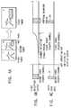
- FIG. 2shows a television device having a function of processing the above text data.
- the television devicehas two systems each including a receiving system such as a tuner for receiving ground waves in order to make full use of the double-screen function.
- a television signal S1 output from a first tuner 11is supplied to a video processing circuit 12.
- a video signal S2 which is an output signal of the video processing circuit 12is supplied to a compression circuit 13 and selection circuit 14.
- a memory(not shown) is connected to the compression circuit 13 so that a compressed still picture can be stored and pictures of the respective channels can be sequentially stored and read out in the channel search mode.
- a video signal output from the compression circuit 13is supplied to the selection circuit 14.
- a video signal S3 selected by the selection circuit 14is converted into an analog signal in a synthesizer circuit 15 and then supplied to a color cathode ray tube 16 for image display.
- a television signal S4 output from a second tuner 17is supplied to a video processing circuit 18.
- a video signal S5 which is an output signal of the video processing circuit 18is supplied to a compression circuit 19 and selection circuit 14.
- a video signal S3 selected by the selection circuit 14is supplied to the color cathode ray tube 16 via the synthesizing circuit 15 and a corresponding image is displayed.
- the output video signal S2 of the video processing circuit 12is supplied to one of two terminals of a selector 24.
- the output video signal S5 of the video processing circuit 18is supplied to the other terminal of the selector 24.
- a signal selected by the selector 24is input to a text data decoder 20. If the text data decoder 20 is switched into a text processing mode via a microcomputer 22 by the operation of a remote controller 21, a text data processing operation is effected. An output signal obtained by the text processing operation is supplied to the synthesizing circuit 15 via an output circuit 23 in which the output timing is controlled. As a result, the text image is superposed on the image output from the selection circuit 14 and displayed.
- the above television deviceis normally constructed such that the video processing circuit 12 has a higher performance and provides an image of higher image quality in comparison with the video processing circuit 18.
- an output signal of the selector 24is supplied to a sync separation circuit 31.
- a synchronizing signal separated in the sync separation circuit 31is supplied to the microcomputer 22.
- the selector 24is controlled by a switching control signal S6 from the microcomputer 22.
- the microcomputer 22is designed to control the switching position of the selector 24 in a period other than the period of the synchronizing signal supplied from the sync separation circuit 31 when controlling the selector 24.
- the channel of the system including the video processing circuit 12is selected to perform the normal image display.
- the one-screen display modeis specified and the output video signal S2 from the video processing circuit 12 is selected by the selection circuit 14, supplied to the color cathode ray tube 16 via the synthesizing circuit 15 and displayed on the color cathode ray tube.
- the video signal S2 of the video processing circuit 12is compressed to 1/2 in the horizontal direction by the compression circuit 13 and the video signal S5 of the video processing circuit 18 is compressed by half in the horizontal direction by the compression circuit 19.
- the selection circuit 14alternately selects the outputs of the compression circuits 13 and 19 for every 1/2 horizontal period and supplies the selected output to the synthesizing circuit 15.
- a video image of a channel selected by the first tuner 11is displayed on the left side of the display screen and a video image of a channel selected by the second tuner 17 is displayed on the right side of the display screen.
- the output video signals of the video processing circuits 12 and 18are supplied to and synchronized by a synchronization processing circuit (not shown) and then output.
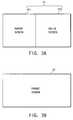
- the television signal S1 received by the first tuner 11is displayed as a parent picture on a left screen 411 of a wide screen 41 as shown in FIG. 3A.
- the television signal S4 received by the second tuner 17is displayed as a child picture on a right screen 412 of the wide screen 41 as shown in FIG. 3A.
- the parent pictureis displayed on the entire area of the wide screen 41 as shown in FIG. 3B.
- a double-screen display statein which a video image of a first channel by the first tuner is displayed on the left screen and text data and a video image of a fourth channel by the second tuner 17 are displayed on the right screen (the text data decoder 20 selects the second tuner 17 side) is set as shown in FIG. 4A. Further, assume that the display state is switched from the present state to a state in which the video image of the fourth channel and text data are displayed on the entire area of the wide screen.
- the operation state of the first tuner 11is switched from a state in which the first channel is received to a state in which the fourth channel is received and an unstable state occurs until the channel selection is completed (refer to FIG. 4B).
- the unstable stateoccurs because it takes a long time to correctly perform the AGC (Automatic Gain Control) and the conversion of PLL (Phase Locked Loop) data of the selection circuit at the time of channel switching. Therefore, in a preset period of time after the screen switching operation has been effected, the reception signal in the system of the first tuner becomes unstable and text data cannot be correctly reproduced (refer to FIG. 4C).
- AGCAutomatic Gain Control
- PLLPhase Locked Loop
- teleshoppingIn the field of application of the text data broadcasting, teleshopping is provided. That is, goods or articles are introduced in a television program, and information such as the article codes of the respective articles and the dealing shops thereof is transmitted as text data. If the channel switching operation described above is effected in such a television program, a telephone number for doing the teleshopping is sometimes lost.
- the screen switching operationis effected as follows so as to prevent occurrence of omission of data.
- FIGS. 5A to 5Eshow the states of outputs and data obtained when the switching position of the selector 24 is controlled in a case where text data is input to the parent screen or child screen. That is, when the display mode is switched from the double-screen display mode to the one-screen display mode by operating the remote controller 21, first, the reception channel of the first tuner 11 is switched to a channel which is the same as the reception channel of the second tuner 17 by a selection control signal from the microcomputer 22. At this time, the selection circuit 14 selects the output signal of the video processing circuit 18 and an image of the television signal S4 (FIG. 5A) output from the second tuner 17 is displayed on the display screen 41. The selector 24 keeps the state in which the video processing circuit 18 is selected.
- the second tuner 17continues to receive the program until the first tuner 11 is set to select a channel for a desired program and the image mute thereof is released.
- the reception channelis switched to the same channel as the reception channel of the second tuner 17. Therefore, the television signal S1 is changed to the channel of the television signal S4 received by the second tuner 17 after a channel selection stable time t1 has passed as shown in FIG. 5B. At the same time, it is subjected to the IF AGC control.
- FIG. 5Cshows a synchronizing signal output from the sync separation circuit 31 and FIG. 5D shows an output of the selector 24.
- the selector 24may effect the switching operation when the synchronizing signal output from the sync separation circuit 31 is at the low level, that is, in a period other than the vertical blanking period.
- the synchronizing signal output from the sync separation circuit 31 shown in FIG. 5Cis input to the microcomputer 22.
- the microcomputer 22sets the channel selection stable time t1 from the operation time of the screen switching key and then changes the switching position of the selector 24 from the second tuner 17 side to the first tuner 11 side in a period of time t2 other than the vertical blanking period. That is, it controls the selector 24 to select the output of the video processing circuit 12.
- the text data decoder 20can receive text data items D3, D4, D5 shown in FIG. 5E derived from the first tuner 11 side. As a result, text data items D1 to D5 are not lost and can be decoded in the text data decoder 20.
- the second tuner 17After input of the text data is switched to the first tuner 11, the second tuner 17 is set to receive another channel or set into the OFF state. Even if the time t2 is set as predetermined fixed time, the object of this invention can be attained. Further, it is possible to provide means for positively monitoring and determining whether or not the reception state of the tuner 11 becomes stable in order to determine the switching timing of the selector 24 and use an output of the monitoring means so as to switch the switching position of the selector 24.
- Switching of the display images on the wide screenis effected by use of the selection circuit 14.
- the switchingcan be effected in the horizontal synchronizing signal period or vertical synchronizing signal period, for example.
- the display modeis switched from the double-screen display mode to the one-screen display mode and the test data reception state of the second tuner side is switched to the text data reception state of the first tuner.
- the concept of this inventionis not limited to the above mode switching operation.
- this inventioncan be applied in a case wherein the switching operation is effected between the reception channel of the first tuner and the reception channel of the second tuner while the state of the double-screen display mode is maintained. More specifically, the reception channels of one of the tuners which now receives text data and the other tuner which is to receive the text data are controlled to overlap in a preset period of time so as to prevent the text data from being lost.
- an output of the other (latter) tuner which now receives the text datais supplied to the text data decoder and then the reception state of the former tuner is controlled.
- the text data decoderselects the output of the former tuner.
- FIG. 6shows another embodiment of this invention.
- an output video signal S2 of the video processing circuit 12 and an output video signal S5 of the video processing circuit 18are supplied to a switching section 51, one of the two output signals of the switching section 51 is supplied to a V/C/D processing circuit 52, and the other output signal thereof is supplied to the compression circuit 19 and selection circuit 14.
- the V/C/D processing circuit 52is a video/chroma/deflection processing circuit, and can adjust the image quality by controlling the luminance signal and can adjust the hue and color balance by controlling the chroma signal. Further, it processes the synchronizing signal for deflection process.
- the V/C/D processing circuit 52processes the output video signal selected and derived by a switch 511 of the switching section 51 and supplies the processed output video signal to the selection circuit 14 and compression circuit 13. Further, the V/C/D processing circuit 52 separates the synchronizing signal from the output video signal selected and derived by the switch 511 of the switching section 51 and supplies the synchronizing signal to the microcomputer 22.
- the switch 511normally selects a signal on the first tuner 11 side and a switch 512 selects a signal on the second tuner 17 side.
- the switching section 51is used to replace the right and left images in the double-screen display mode. That is, if the switch 511 is set to select the output on the tuner 17 side and the switch 512 is set to select the output on the tuner 11 side, the images of the right and left positions can be replaced with each other.
- the display stateis switched from the double-screen display state to the one-screen display state as shown in FIG. 4A like the case of the former embodiment.
- the switch 511is switched to the second tuner 17 side based on a switching control signal from the microcomputer 22. Therefore, the V/C/D processing circuit 52 processes the output video signal of the same program as that of the output video signal selected and derived by the switch 512.
- the selection circuit 14selects the output signal of the V/C/D processing circuit 52 and outputs the same as a signal for the wide display screen. Further, the reception state of the first tuner 11 is set to the reception state of a channel which is the same as the reception channel of the second tuner 17 in which the text broadcasting is performed.
- the reception state of the first tuner 11becomes stable when a preset period of time has passed. Then, the microcomputer 22 controls the switch 511 to select the video signal on the first tuner 11 side. Further, when the switching position of the selector 24 is switched, the microcomputer 22 monitors the synchronizing signal from the V/C/D processing circuit 52 and controls the selector 24 to select the signal on the first tuner 11 side in a period other than the period of the vertical synchronizing signal.
- text datacan be continuously received even when the switching operation of reception between a plurality of tuners is effected and the text data process of high reliability can be attained.
- FIG. 7shows an example of the concrete construction of the text data decoder.
- a video signalis input to a sync separation section 122 and A/D converter 123 via an input terminal 121.
- Digital data explained with reference to FIG. 1is superposed on the vertical blanking period of the video signal.
- Data converted into the digital form in the A/D converter 123is subjected to the waveform equalization process in a waveform equalizing section 124 and supplied to a data fetching/error correcting section 125.
- the data fetching/error correcting section 125fetches a text signal based on the timing signal from the sync separation section 122 and performs the error correction process.
- a CPU 127is operated based on a fixed program stored in a program ROM 128.
- program ROM 128In a character font ROM 129, character fonts for displaying characters are stored and character data can be read out by causing the CPU 127 to address a desired character in the character font ROM 129.
- a display synchronizing signal which is synchronized with the operation of the television deviceis supplied to an input terminal 130.
- the synchronizing signalis supplied to a display control section 131.
- the display control section 131effects the process for reading out data of a display memory 132 in synchronism with reproduction of a television image and writing display data into the display memory 132 in response to a write instruction from the CPU 127.
- the color map memory 133receives display data as an address input and outputs level data of primary color signals R, G, B corresponding to the address.
- the level datais converted to analog R, G, B signals by a D/A converter 134 and they are derived from an output terminal as a display signal.
- the display signalis synthesized with the television signal by synthesizing means (not shown) and displayed on the display. Further, the D/A converter 134 can be omitted and the R, G, B signals output from the color map memory 133 can be used as they are depending on the type of an interface on the display side.
- An operation signal generated from the operating section of the remote controller operated by the vieweris input via an input terminal 136.
- the operation signalis fetched by the CPU 127 via an operation input interface (I/F) 137 and then analyzed.
- I/Foperation input interface
- a modem 138contains a modulator and demodulator to construct a communication control section and is connected to a telephone line 140 via a line connecting section 139.
- the line connecting section 139controls connection/disconnection to or from the telephone line 140 and is controlled by the CPU 127.
- the CPU 127is connected to function blocks, that is, the data fetching/error correcting section 125, program ROM 128, character font ROM 129, operation input interface 137, work RAM 141, program RAM 142 and nonvolatile memory 143 via the bus line.
- the program RAM 142is a memory for storing a script (computer program) transmitted from the broadcasting station, the content of the script is interpreted according to an interpreter in the fixed program stored in the ROM 128 by the operation of the viewer and a preset process can be executed according to the procedure.
- a scriptcomputer program
- a fixed identification number (ID) of the reception terminalis stored in the nonvolatile memory 143 and when order data is transmitted to the data collecting station in the teleshopping, for example, the identification number is used.
- the ordereris determined by recognizing the identification number.
- the above circuit constructionis used when the multiplexed text broadcasting program is processed. That is, if reception of the multiplexed text broadcasting program is specified by the operation of the remote controller, the CPU 127 is switched to be put under control of the multiplexed text broadcast processing program stored in the program ROM 128. Then, transmitted character data is converted to display data in the character font ROM 129 and stored into the display memory 132 via the display control section 131.
Landscapes
- Engineering & Computer Science (AREA)
- Multimedia (AREA)
- Signal Processing (AREA)
- Business, Economics & Management (AREA)
- Marketing (AREA)
- Television Systems (AREA)
- Two-Way Televisions, Distribution Of Moving Picture Or The Like (AREA)
Abstract
Description
Claims (5)
- A television device having a text dataprocessing function characterized by comprising:a first tuner (11);a first signal processing system (12) for processingan output signal of said first tuner;a second tuner (12);a second signal processing system (18) for processingan output signal of said second tuner;a selector (24) for selectively supplying anoutput signal of one of said first and second signalprocessing systems to a text decoder (20); andcontrol means for controlling the operation ofthe television device;
wherein said control means (22) keeps the channelselecting states of said first and second tuners in anoverlapped state for a preset period of time when saidfirst tuner is selected to receive a channel which isthe same as a channel received by said second tunerunder a condition that said control means controls saidselector (24) to cause an output signal of said secondsignal processing system to be supplied to said textdecoder, and controls said selector to supply areception output of said first tuner to said textdecoder when the reception state of said first tunerbecomes stable. - A television device having a text data processingfunction according to claim 1, characterizedin that said control means controls the switchingoperation of said selector in a period other than thevertical blanking period of an output signal of saidfirst tuner.
- A television device having a text data processingfunction according to claim 1, characterizedin that the text data is inter text data.
- A television device having a text data processing function comprising:reception means (11, 12, 17, 18) having at leastfirst and second tuners and capable of receiving anddemodulating television broadcasting signals of twochannels;video signal processing means (13, 14, 19) forindependently displaying a video signal which is areception signal of said first tuner or compressingat least one of video signals which are receptionsignals of said first and second tuners to simultaneouslydisplay the video signals on a display device;selector means (24) for selectively deriving thetelevision broadcasting signals received by said firstand second tuners;text receiving/demodulating means (20) for receivingan output of said selector means and receiving anddemodulating transmitted text data superposed on a datachannel contained in the television broadcasting signaland independent from the video/audio signal thereof;text synthesizing means (15, 23) for synthesizingthe text data demodulated by said text receiving/demodulatingmeans (20) with an output of said videosignal processing means;synchronization separation means (31) for separatinga synchronizing signal from an output of saidselector means; andswitching control means (22) for controlling theswitching operation of said selector means in a periodother than the vertical blanking period based on thesynchronizing signal from said synchronization separationmeans after the channel selection becomes stablein a case where a selected channel of said first tuneris switched to a channel selected by said second tuner.
- A television device having a text dataprocessing function according to claim 4, characterizedby further comprising channel selection control meansfor controlling said first and second tuners to temporarily receive the same channel program in a casewhere a reception channel of said first tuner isswitched to a channel received by said second tuner;and means for setting said second tuner to anotherchannel or setting said second tuner into an OFF stateafter the selection channel of said first tuner isswitched.
Applications Claiming Priority (3)
| Application Number | Priority Date | Filing Date | Title |
|---|---|---|---|
| JP17643396 | 1996-07-05 | ||
| JP176433/96 | 1996-07-05 | ||
| JP8176433AJPH1023377A (en) | 1996-07-05 | 1996-07-05 | Text data processing device using television receiver |
Publications (3)
| Publication Number | Publication Date |
|---|---|
| EP0817483A2true EP0817483A2 (en) | 1998-01-07 |
| EP0817483A3 EP0817483A3 (en) | 1999-04-21 |
| EP0817483B1 EP0817483B1 (en) | 2005-09-14 |
Family
ID=16013626
Family Applications (1)
| Application Number | Title | Priority Date | Filing Date |
|---|---|---|---|
| EP97111327AExpired - LifetimeEP0817483B1 (en) | 1996-07-05 | 1997-07-04 | Television device having text data processing function |
Country Status (7)
| Country | Link |
|---|---|
| US (1) | US6011594A (en) |
| EP (1) | EP0817483B1 (en) |
| JP (1) | JPH1023377A (en) |
| KR (1) | KR980013311A (en) |
| CN (1) | CN1173095A (en) |
| DE (1) | DE69734176T2 (en) |
| TW (1) | TW366664B (en) |
Cited By (7)
| Publication number | Priority date | Publication date | Assignee | Title |
|---|---|---|---|---|
| EP1280345A3 (en)* | 2001-07-19 | 2005-04-20 | Victor Company Of Japan, Ltd. | Apparatus, method and program for video signal recording/reproduction |
| US7529465B2 (en) | 1998-07-30 | 2009-05-05 | Tivo Inc. | System for time shifting multimedia content streams |
| US7558472B2 (en) | 2000-08-22 | 2009-07-07 | Tivo Inc. | Multimedia signal processing system |
| US8380041B2 (en) | 1998-07-30 | 2013-02-19 | Tivo Inc. | Transportable digital video recorder system |
| US8380049B2 (en) | 1998-05-06 | 2013-02-19 | Tivo Inc. | Playback of audio/video content with control codes |
| US8577205B2 (en) | 1998-07-30 | 2013-11-05 | Tivo Inc. | Digital video recording system |
| US9967534B1 (en) | 2004-11-19 | 2018-05-08 | Tivo Solutions Inc. | Digital video recorder video editing system |
Families Citing this family (36)
| Publication number | Priority date | Publication date | Assignee | Title |
|---|---|---|---|---|
| US6341195B1 (en)* | 1994-12-28 | 2002-01-22 | E-Guide, Inc. | Apparatus and methods for a television on-screen guide |
| JP3494555B2 (en)* | 1997-07-14 | 2004-02-09 | 株式会社日立製作所 | Display device and display method |
| JPH11196249A (en)* | 1997-12-26 | 1999-07-21 | Funai Electric Co Ltd | Image communication equipment |
| DE59906518D1 (en)* | 1998-04-22 | 2003-09-11 | Micronas Munich Gmbh | RECEIVER FOR RECEIVING VIDEO AND TELETEX SIGNALS |
| US6563515B1 (en)* | 1998-05-19 | 2003-05-13 | United Video Properties, Inc. | Program guide system with video window browsing |
| US6519283B1 (en)* | 1999-01-25 | 2003-02-11 | International Business Machines Corporation | Integrated video processing system having multiple video sources and implementing picture-in-picture with on-screen display graphics |
| KR100313901B1 (en)* | 1999-02-08 | 2001-11-17 | 구자홍 | Apparatus for sub-picture processing in television receiver |
| US6587153B1 (en)* | 1999-10-08 | 2003-07-01 | Matsushita Electric Industrial Co., Ltd. | Display apparatus |
| JP2001346121A (en)* | 2000-05-31 | 2001-12-14 | Nec Corp | Display device with two-screen function |
| FR2819671B1 (en)* | 2001-01-17 | 2003-05-16 | Thomson Licensing Sa | RECEIVING SYSTEM FOR MULTI-TUNER TELEVISION FOR AUTOMATICALLY CONNECTING EACH TUNER TO AT LEAST ONE ANTENNA, WHATEVER THE NUMBER OF ANTENNAS IT CONTAINS |
| EP1274236A1 (en)* | 2001-07-05 | 2003-01-08 | Thomson Licensing S.A. | Video apparatus with picture-in-picture ability |
| US7080124B1 (en)* | 2001-08-21 | 2006-07-18 | Amazon Technologies, Inc. | Digital media resource messaging |
| US6980257B2 (en)* | 2002-11-18 | 2005-12-27 | Sharp Laboratories Of America, Inc. | Plural-source, selectable, combined image/text single-screen display |
| KR100873437B1 (en)* | 2002-11-28 | 2008-12-11 | 삼성전자주식회사 | Dual mode signal processing device using PI screen |
| JP2004193925A (en)* | 2002-12-11 | 2004-07-08 | Orion Denki Kk | Program receiving system |
| US6848792B1 (en)* | 2002-12-27 | 2005-02-01 | Barco N.V. | Full resolution multiple image projection system and method for projecting two images in full resolution adjacent each other |
| KR100976467B1 (en)* | 2003-05-13 | 2010-08-18 | 엘지전자 주식회사 | Digital TV Receiver for Teletext Information Processing |
| US7400360B2 (en)* | 2003-09-22 | 2008-07-15 | Lsi Corporation | Device for simultaneous display of video at two resolutions with different fractions of active regions |
| US20050086702A1 (en)* | 2003-10-17 | 2005-04-21 | Cormack Christopher J. | Translation of text encoded in video signals |
| MXPA06014588A (en)* | 2004-06-14 | 2007-03-01 | Thomson Licensing | System and method for changing television channels in a video signal processor. |
| US7432981B1 (en)* | 2004-12-13 | 2008-10-07 | Nvidia Corporation | Apparatus, system, and method for processing digital audio/video signals |
| TWI307081B (en)* | 2005-03-24 | 2009-03-01 | Via Tech Inc | Multi-view video switch control method and system |
| US7532253B1 (en)* | 2005-07-26 | 2009-05-12 | Pixelworks, Inc. | Television channel change picture-in-picture circuit and method |
| TWI308308B (en)* | 2005-08-12 | 2009-04-01 | Au Optronics Corp | Driving circuits and driving modules, display systems and electronic devices using the same |
| JP2008011085A (en)* | 2006-06-28 | 2008-01-17 | Toshiba Corp | Digital TV capture unit, information processing apparatus, and signal transmission method |
| KR100803139B1 (en) | 2006-08-07 | 2008-02-14 | 엘지전자 주식회사 | Broadcast receiver with dynamic screen switching function and control method |
| JP5242111B2 (en)* | 2007-10-02 | 2013-07-24 | 株式会社ソニー・コンピュータエンタテインメント | Transmitting apparatus, image data transmitting method, receiving apparatus, and image display method in receiving apparatus |
| US8165450B2 (en) | 2007-11-19 | 2012-04-24 | Echostar Technologies L.L.C. | Methods and apparatus for filtering content in a video stream using text data |
| US8165451B2 (en) | 2007-11-20 | 2012-04-24 | Echostar Technologies L.L.C. | Methods and apparatus for displaying information regarding interstitials of a video stream |
| JP4731586B2 (en)* | 2008-05-29 | 2011-07-27 | 京セラ株式会社 | Program guide display device |
| US8156520B2 (en) | 2008-05-30 | 2012-04-10 | EchoStar Technologies, L.L.C. | Methods and apparatus for presenting substitute content in an audio/video stream using text data |
| JP2010048976A (en)* | 2008-08-20 | 2010-03-04 | Sony Corp | Signal processing device and signal processing method |
| US8934758B2 (en) | 2010-02-09 | 2015-01-13 | Echostar Global B.V. | Methods and apparatus for presenting supplemental content in association with recorded content |
| US8698958B2 (en) | 2010-06-16 | 2014-04-15 | Silicon Image, Inc. | Mechanism for memory reduction in picture-in-picture video generation |
| US10622018B2 (en)* | 2015-10-16 | 2020-04-14 | Tribune Broadcasting Company, Llc | Video-production system with metadata-based DVE feature |
| US11172269B2 (en) | 2020-03-04 | 2021-11-09 | Dish Network L.L.C. | Automated commercial content shifting in a video streaming system |
Family Cites Families (20)
| Publication number | Priority date | Publication date | Assignee | Title |
|---|---|---|---|---|
| DE3243610A1 (en)* | 1982-11-25 | 1984-05-30 | Philips Patentverwaltung Gmbh, 2000 Hamburg | ARRANGEMENT FOR PROGRAMMABLE CONTROL OF A BROADCASTING AND / OR TELEVISION RECEIVING DEVICE |
| DE3617251A1 (en)* | 1986-05-22 | 1987-11-26 | Philips Patentverwaltung | CIRCUIT ARRANGEMENT FOR A TELEVISION RECEIVER WITH A VIDEO TEXT DECODER |
| US5121476A (en)* | 1988-02-22 | 1992-06-09 | Yee Keen Y | TV data capture device |
| JPH02198284A (en)* | 1989-01-27 | 1990-08-06 | Fujitsu General Ltd | Television receiver |
| JPH05328319A (en)* | 1992-05-18 | 1993-12-10 | Matsushita Electric Ind Co Ltd | Television receiver |
| EP0656727B1 (en)* | 1993-11-03 | 1999-04-28 | SONY-WEGA PRODUKTIONS GmbH | Teletext receiver |
| JP3256619B2 (en)* | 1993-12-24 | 2002-02-12 | 株式会社東芝 | Character information display |
| FR2717026B1 (en)* | 1994-03-01 | 1996-03-29 | Thomson Consumer Electronics | Tuner programming method and implementation device. |
| JP3029175B2 (en)* | 1994-03-14 | 2000-04-04 | 株式会社日立製作所 | Method of assembling high-voltage power equipment and working device used for the same |
| JPH08140064A (en)* | 1994-11-04 | 1996-05-31 | Sony Corp | Teletext receiver |
| DE19548957C2 (en)* | 1994-12-28 | 1999-12-16 | Lg Electronics Inc | Automatic channel search procedure for a television receiver |
| JP3393356B2 (en)* | 1995-05-26 | 2003-04-07 | ソニー株式会社 | Receiving device and receiving method |
| KR0144890B1 (en)* | 1995-05-27 | 1998-07-15 | 김광호 | Caption and text broadcasting display device and method in double screen TV |
| JPH0970025A (en)* | 1995-08-31 | 1997-03-11 | Toshiba Corp | Television receiver |
| KR0147662B1 (en)* | 1995-08-31 | 1998-09-15 | 김광호 | Control method using transmission graphic in double/wide tv with double deck vcr and cd-ok system |
| KR100197838B1 (en)* | 1995-09-14 | 1999-06-15 | 윤종용 | Information Television's Signal Selection Circuit |
| JPH0993505A (en)* | 1995-09-26 | 1997-04-04 | Toshiba Corp | Television receiver with character multiplex decoder |
| JPH0993548A (en)* | 1995-09-27 | 1997-04-04 | Toshiba Corp | TV receiver with text information display function |
| US5801785A (en)* | 1996-02-13 | 1998-09-01 | International Business Machines Corporation | Method and system for processing two analog composite video signals |
| US5900916A (en)* | 1996-12-30 | 1999-05-04 | Mitsubishi Consumer Electronics America, Inc. | Apparatus for control of images from multiple sources |
- 1996
- 1996-07-05JPJP8176433Apatent/JPH1023377A/enactivePending
- 1997
- 1997-06-26TWTW086108988Apatent/TW366664B/enactive
- 1997-07-02KRKR1019970030558Apatent/KR980013311A/ennot_activeWithdrawn
- 1997-07-03USUS08/888,240patent/US6011594A/ennot_activeExpired - Fee Related
- 1997-07-04EPEP97111327Apatent/EP0817483B1/ennot_activeExpired - Lifetime
- 1997-07-04DEDE69734176Tpatent/DE69734176T2/ennot_activeExpired - Fee Related
- 1997-07-04CNCN97114076Apatent/CN1173095A/enactivePending
Cited By (10)
| Publication number | Priority date | Publication date | Assignee | Title |
|---|---|---|---|---|
| US8380049B2 (en) | 1998-05-06 | 2013-02-19 | Tivo Inc. | Playback of audio/video content with control codes |
| US9094724B2 (en) | 1998-05-06 | 2015-07-28 | Tivo Inc. | Multi-channel playback of audio/video content |
| US9113212B2 (en) | 1998-05-06 | 2015-08-18 | Tivo Inc. | Simultaneous recording and playback of audio/video programs |
| US7529465B2 (en) | 1998-07-30 | 2009-05-05 | Tivo Inc. | System for time shifting multimedia content streams |
| US8380041B2 (en) | 1998-07-30 | 2013-02-19 | Tivo Inc. | Transportable digital video recorder system |
| US8577205B2 (en) | 1998-07-30 | 2013-11-05 | Tivo Inc. | Digital video recording system |
| US7558472B2 (en) | 2000-08-22 | 2009-07-07 | Tivo Inc. | Multimedia signal processing system |
| EP1280345A3 (en)* | 2001-07-19 | 2005-04-20 | Victor Company Of Japan, Ltd. | Apparatus, method and program for video signal recording/reproduction |
| US7283722B2 (en) | 2001-07-19 | 2007-10-16 | Victor Company Of Japan, Ltd. | Apparatus and method for reproducing video signals as they are recorded |
| US9967534B1 (en) | 2004-11-19 | 2018-05-08 | Tivo Solutions Inc. | Digital video recorder video editing system |
Also Published As
| Publication number | Publication date |
|---|---|
| US6011594A (en) | 2000-01-04 |
| EP0817483A3 (en) | 1999-04-21 |
| DE69734176D1 (en) | 2005-10-20 |
| HK1007921A1 (en) | 1999-04-30 |
| EP0817483B1 (en) | 2005-09-14 |
| CN1173095A (en) | 1998-02-11 |
| DE69734176T2 (en) | 2006-06-29 |
| JPH1023377A (en) | 1998-01-23 |
| KR980013311A (en) | 1998-04-30 |
| TW366664B (en) | 1999-08-11 |
Similar Documents
| Publication | Publication Date | Title |
|---|---|---|
| EP0817483B1 (en) | Television device having text data processing function | |
| US5708475A (en) | Receiving apparatus and receiving method | |
| US5512954A (en) | Television receiver with decoder for decoding coded data from a video signal | |
| EP1265439B1 (en) | Video signal processing system with auxiliary information processing capability | |
| KR100320267B1 (en) | TV receiver | |
| US6459456B1 (en) | Digital receiver apparatus capable of receiving multiple channels and having display function control method | |
| US6204884B1 (en) | Multisystem television which is usable as a monitor of a personal computer and a method thereof | |
| JPH04107079A (en) | Television receiver | |
| US6727960B2 (en) | Television channel selection method and apparatus | |
| JPH11164215A (en) | Television receiver | |
| US5986716A (en) | Television receiver and signal processing apparatus | |
| JP2003116073A (en) | Television broadcast receiver | |
| EP0881842B1 (en) | A device for providing a monitor output signal in a high-definition television | |
| JP2000270277A (en) | Television receiver | |
| JPH05316447A (en) | Television receiver | |
| JP2001268460A (en) | Method of changing the channel of a television receiver and a corresponding television receiver | |
| JPH09135394A (en) | Television receiver for digital broadcasting | |
| HK1007921B (en) | Television device having text data processing function | |
| JPH11355688A (en) | Multi-screen display device | |
| JP2001186436A (en) | Electronic program display device | |
| JP2001186435A (en) | Television program display device | |
| JPH1155592A (en) | Television receiver | |
| JPH06133240A (en) | Osd display device | |
| JP2001036835A (en) | Multi-channel television receiver | |
| JP3013217B2 (en) | Inline screen linearity controller |
Legal Events
| Date | Code | Title | Description |
|---|---|---|---|
| PUAI | Public reference made under article 153(3) epc to a published international application that has entered the european phase | Free format text:ORIGINAL CODE: 0009012 | |
| 17P | Request for examination filed | Effective date:19970801 | |
| AK | Designated contracting states | Kind code of ref document:A2 Designated state(s):DE GB IT | |
| PUAL | Search report despatched | Free format text:ORIGINAL CODE: 0009013 | |
| AK | Designated contracting states | Kind code of ref document:A3 Designated state(s):AT BE CH DE DK ES FI FR GB GR IE IT LI LU MC NL PT SE | |
| RIN1 | Information on inventor provided before grant (corrected) | Inventor name:TAKASHIMA, TADAO | |
| AKX | Designation fees paid | Free format text:DE GB IT | |
| 17Q | First examination report despatched | Effective date:20031103 | |
| GRAP | Despatch of communication of intention to grant a patent | Free format text:ORIGINAL CODE: EPIDOSNIGR1 | |
| GRAS | Grant fee paid | Free format text:ORIGINAL CODE: EPIDOSNIGR3 | |
| GRAA | (expected) grant | Free format text:ORIGINAL CODE: 0009210 | |
| AK | Designated contracting states | Kind code of ref document:B1 Designated state(s):DE GB IT | |
| REG | Reference to a national code | Ref country code:GB Ref legal event code:FG4D | |
| REF | Corresponds to: | Ref document number:69734176 Country of ref document:DE Date of ref document:20051020 Kind code of ref document:P | |
| REG | Reference to a national code | Ref country code:HK Ref legal event code:GR Ref document number:1007921 Country of ref document:HK | |
| PGFP | Annual fee paid to national office [announced via postgrant information from national office to epo] | Ref country code:GB Payment date:20060628 Year of fee payment:10 | |
| PGFP | Annual fee paid to national office [announced via postgrant information from national office to epo] | Ref country code:DE Payment date:20060629 Year of fee payment:10 | |
| PLBE | No opposition filed within time limit | Free format text:ORIGINAL CODE: 0009261 | |
| STAA | Information on the status of an ep patent application or granted ep patent | Free format text:STATUS: NO OPPOSITION FILED WITHIN TIME LIMIT | |
| PGFP | Annual fee paid to national office [announced via postgrant information from national office to epo] | Ref country code:IT Payment date:20060731 Year of fee payment:10 | |
| 26N | No opposition filed | Effective date:20060615 | |
| GBPC | Gb: european patent ceased through non-payment of renewal fee | Effective date:20070704 | |
| PG25 | Lapsed in a contracting state [announced via postgrant information from national office to epo] | Ref country code:DE Free format text:LAPSE BECAUSE OF NON-PAYMENT OF DUE FEES Effective date:20080201 | |
| PG25 | Lapsed in a contracting state [announced via postgrant information from national office to epo] | Ref country code:GB Free format text:LAPSE BECAUSE OF NON-PAYMENT OF DUE FEES Effective date:20070704 | |
| PG25 | Lapsed in a contracting state [announced via postgrant information from national office to epo] | Ref country code:IT Free format text:LAPSE BECAUSE OF NON-PAYMENT OF DUE FEES Effective date:20070704 |