EP0816551A2 - Infrared temperature sensing for tumble drying control - Google Patents
Infrared temperature sensing for tumble drying controlDownload PDFInfo
- Publication number
- EP0816551A2 EP0816551A2EP97109804AEP97109804AEP0816551A2EP 0816551 A2EP0816551 A2EP 0816551A2EP 97109804 AEP97109804 AEP 97109804AEP 97109804 AEP97109804 AEP 97109804AEP 0816551 A2EP0816551 A2EP 0816551A2
- Authority
- EP
- European Patent Office
- Prior art keywords
- dryer
- temperature
- drum
- articles
- drying
- Prior art date
- Legal status (The legal status is an assumption and is not a legal conclusion. Google has not performed a legal analysis and makes no representation as to the accuracy of the status listed.)
- Granted
Links
- 238000001035dryingMethods0.000titleclaimsabstractdescription89
- 238000000034methodMethods0.000claimsabstractdescription29
- 238000005259measurementMethods0.000claimsdescription29
- XLYOFNOQVPJJNP-UHFFFAOYSA-NwaterSubstancesOXLYOFNOQVPJJNP-UHFFFAOYSA-N0.000claimsdescription21
- 238000010438heat treatmentMethods0.000claimsdescription14
- 230000000007visual effectEffects0.000claimsdescription4
- 238000012935AveragingMethods0.000claimsdescription3
- 239000000446fuelSubstances0.000claimsdescription3
- 230000001276controlling effectEffects0.000claims2
- 230000001105regulatory effectEffects0.000claims1
- 238000007796conventional methodMethods0.000abstract1
- 239000003570airSubstances0.000description30
- 239000000523sampleSubstances0.000description11
- 238000013459approachMethods0.000description7
- 238000009529body temperature measurementMethods0.000description5
- 239000012080ambient airSubstances0.000description3
- 241000220317RosaSpecies0.000description2
- 239000013256coordination polymerSubstances0.000description2
- 230000006870functionEffects0.000description2
- 238000012360testing methodMethods0.000description2
- 239000002699waste materialSubstances0.000description2
- 238000005303weighingMethods0.000description2
- 238000010420art techniqueMethods0.000description1
- 238000011217control strategyMethods0.000description1
- 230000003247decreasing effectEffects0.000description1
- 230000007613environmental effectEffects0.000description1
- 238000001704evaporationMethods0.000description1
- 230000008020evaporationEffects0.000description1
- 238000002474experimental methodMethods0.000description1
- 230000000977initiatory effectEffects0.000description1
- 230000005055memory storageEffects0.000description1
- 238000012986modificationMethods0.000description1
- 230000004048modificationEffects0.000description1
- 230000000717retained effectEffects0.000description1
- 230000000630rising effectEffects0.000description1
- 238000011144upstream manufacturingMethods0.000description1
- 238000009834vaporizationMethods0.000description1
Images


Classifications
- D—TEXTILES; PAPER
- D06—TREATMENT OF TEXTILES OR THE LIKE; LAUNDERING; FLEXIBLE MATERIALS NOT OTHERWISE PROVIDED FOR
- D06F—LAUNDERING, DRYING, IRONING, PRESSING OR FOLDING TEXTILE ARTICLES
- D06F58/00—Domestic laundry dryers
- D06F58/30—Drying processes
- D—TEXTILES; PAPER
- D06—TREATMENT OF TEXTILES OR THE LIKE; LAUNDERING; FLEXIBLE MATERIALS NOT OTHERWISE PROVIDED FOR
- D06F—LAUNDERING, DRYING, IRONING, PRESSING OR FOLDING TEXTILE ARTICLES
- D06F34/00—Details of control systems for washing machines, washer-dryers or laundry dryers
- D06F34/14—Arrangements for detecting or measuring specific parameters
- D06F34/18—Condition of the laundry, e.g. nature or weight
- D—TEXTILES; PAPER
- D06—TREATMENT OF TEXTILES OR THE LIKE; LAUNDERING; FLEXIBLE MATERIALS NOT OTHERWISE PROVIDED FOR
- D06F—LAUNDERING, DRYING, IRONING, PRESSING OR FOLDING TEXTILE ARTICLES
- D06F2103/00—Parameters monitored or detected for the control of domestic laundry washing machines, washer-dryers or laundry dryers
- D06F2103/02—Characteristics of laundry or load
- D06F2103/08—Humidity
- D—TEXTILES; PAPER
- D06—TREATMENT OF TEXTILES OR THE LIKE; LAUNDERING; FLEXIBLE MATERIALS NOT OTHERWISE PROVIDED FOR
- D06F—LAUNDERING, DRYING, IRONING, PRESSING OR FOLDING TEXTILE ARTICLES
- D06F2103/00—Parameters monitored or detected for the control of domestic laundry washing machines, washer-dryers or laundry dryers
- D06F2103/02—Characteristics of laundry or load
- D06F2103/12—Temperature
- D—TEXTILES; PAPER
- D06—TREATMENT OF TEXTILES OR THE LIKE; LAUNDERING; FLEXIBLE MATERIALS NOT OTHERWISE PROVIDED FOR
- D06F—LAUNDERING, DRYING, IRONING, PRESSING OR FOLDING TEXTILE ARTICLES
- D06F2103/00—Parameters monitored or detected for the control of domestic laundry washing machines, washer-dryers or laundry dryers
- D06F2103/28—Air properties
- D06F2103/32—Temperature
- D—TEXTILES; PAPER
- D06—TREATMENT OF TEXTILES OR THE LIKE; LAUNDERING; FLEXIBLE MATERIALS NOT OTHERWISE PROVIDED FOR
- D06F—LAUNDERING, DRYING, IRONING, PRESSING OR FOLDING TEXTILE ARTICLES
- D06F2103/00—Parameters monitored or detected for the control of domestic laundry washing machines, washer-dryers or laundry dryers
- D06F2103/64—Radiation, e.g. microwaves
- D—TEXTILES; PAPER
- D06—TREATMENT OF TEXTILES OR THE LIKE; LAUNDERING; FLEXIBLE MATERIALS NOT OTHERWISE PROVIDED FOR
- D06F—LAUNDERING, DRYING, IRONING, PRESSING OR FOLDING TEXTILE ARTICLES
- D06F2105/00—Systems or parameters controlled or affected by the control systems of washing machines, washer-dryers or laundry dryers
- D06F2105/16—Air properties
- D06F2105/20—Temperature
- D—TEXTILES; PAPER
- D06—TREATMENT OF TEXTILES OR THE LIKE; LAUNDERING; FLEXIBLE MATERIALS NOT OTHERWISE PROVIDED FOR
- D06F—LAUNDERING, DRYING, IRONING, PRESSING OR FOLDING TEXTILE ARTICLES
- D06F2105/00—Systems or parameters controlled or affected by the control systems of washing machines, washer-dryers or laundry dryers
- D06F2105/58—Indications or alarms to the control system or to the user
- D—TEXTILES; PAPER
- D06—TREATMENT OF TEXTILES OR THE LIKE; LAUNDERING; FLEXIBLE MATERIALS NOT OTHERWISE PROVIDED FOR
- D06F—LAUNDERING, DRYING, IRONING, PRESSING OR FOLDING TEXTILE ARTICLES
- D06F34/00—Details of control systems for washing machines, washer-dryers or laundry dryers
- D06F34/04—Signal transfer or data transmission arrangements
- D—TEXTILES; PAPER
- D06—TREATMENT OF TEXTILES OR THE LIKE; LAUNDERING; FLEXIBLE MATERIALS NOT OTHERWISE PROVIDED FOR
- D06F—LAUNDERING, DRYING, IRONING, PRESSING OR FOLDING TEXTILE ARTICLES
- D06F34/00—Details of control systems for washing machines, washer-dryers or laundry dryers
- D06F34/08—Control circuits or arrangements thereof
- D—TEXTILES; PAPER
- D06—TREATMENT OF TEXTILES OR THE LIKE; LAUNDERING; FLEXIBLE MATERIALS NOT OTHERWISE PROVIDED FOR
- D06F—LAUNDERING, DRYING, IRONING, PRESSING OR FOLDING TEXTILE ARTICLES
- D06F58/00—Domestic laundry dryers
- D06F58/32—Control of operations performed in domestic laundry dryers
- D06F58/34—Control of operations performed in domestic laundry dryers characterised by the purpose or target of the control
- D06F58/36—Control of operational steps, e.g. for optimisation or improvement of operational steps depending on the condition of the laundry
- D06F58/38—Control of operational steps, e.g. for optimisation or improvement of operational steps depending on the condition of the laundry of drying, e.g. to achieve the target humidity
Definitions
- the present inventionrelates to infrared temperature sensing for drying devices, and particularly for clothes dryers.
- the present inventionachieves all of the foregoing objectives and provides a dryer comprising an infrared sensing device that measures and indicates the temperature of articles in the dryer.
- the present inventionprovides a rotatable drum dryer comprising an infrared sensing device that provides either an analog or digital signal representative of the temperature of articles in the dryer.
- the infrared sensing devicemay also provide a visual indication of the temperature of articles in the dryer.
- a rotatable drum dryerutilizing two such infrared sensing devices.
- the inventionfurther provides a dryer control system comprising an infrared sensing device in combination with other sensors.
- the present inventionprovides a control system utilizing the infrared sensing device in combination with a temperature sensor exposed to air in the dryer inlet or a temperature sensor exposed to air in the dryer outlet, and optionally, a second infrared sensing device.
- the methods for determining drying cycle completioninclude comparing the rate of temperature increase of articles in the dryer with one or more preset or predetermined values. Also included is a technique in which the temperature of articles in the dryer is compared to a preset temperature value.
- the inventionfurther provides a method for controlling drying temperature by comparing the temperatures of articles in the dryer and dryer exhaust with predetermined setpoint values and idealized time curves.
- the inventionprovides another method for controlling drying temperatures by use of a ratio of two drying parameters determined from a particular combination of measurement inputs.
- FIG. 1illustrates a preferred embodiment drying system 10 in accordance with the present invention generally comprising a dryer unit 30, a blower unit 20, a dryer air inlet temperature sensor 40, a dryer air outlet temperature sensor 50, one or more infrared sensors 60, and a dryer control unit 70.
- the blower unit 20generates and draws airstream A through a dryer air inlet as known in the art to the dryer 30. The entering air passes over articles in the dryer whereby moisture is removed from the articles. Airstream B exits the dryer 30 and the blower unit 20 through one or more exhaust outlets as known in the art.
- the dryer 30includes provisions for heating the inlet airstream A and/or the dryer interior, and for receiving and tumbling moist or wet articles such as in a rotatable drum or basket.
- the blower 20is downstream of the drum and a heater is upstream of the drum. Thus, the blower 20 draws heated air into and through the drum.
- the inlet temperature sensor 40measures the temperature of the inlet airstream A and provides one or more control signals to the controller 70 via a signal line 42.
- the outlet temperature sensor 50provides a measurement of the temperature of the outlet air in airstream B through a signal line 52 to the controller 70.
- the outlet temperature sensor 40is disposed at an output from the blower 20, or within the housing of the blower 20.
- the infrared sensor 60is preferably disposed at or immediately adjacent the container or drum of the dryer 30 containing the articles or garments to be dried as explained in greater detail below.
- the sensor 60provides an indication or measurement of the actual temperature of garments in the dryer 30.
- the sensor 60preferably provides one or more control signals to the controller 70 through a signal line 62.
- the control signalscorrespond to the temperature of the articles in the dryer.
- the control signalsmay be either analog or digital.
- the infrared sensor 60is preferably disposed such that its sensing field or view is exposed to the maximum surface area of garments residing in the dryer. In many applications involving drum dryers, the sensor 60 is mounted along the axis of rotation of the drum.
- the senor 60can be mounted directly on the dryer door, such as by replacing a dryer door window port with a panel containing the infrared sensor 60. It is also contemplated that the sensor 60 may be mounted along other regions of a dryer providing a view of the interior of the dryer drum and of the garments disposed therein.
- the infrared sensors 60do not measure air temperature within dryer 30. Instead, the sensors measure actual surface temperatures of the garments being dried.
- infrared sensorsmay be used in the present invention.
- the preferred sensoris an EXERGEN Model IRT ⁇ C.2--140°F ⁇ 60°C. Other comparable sensor units are also acceptable. It is preferred that the infrared sensor have an accuracy within at least two percent at 80°F to 180°F, and at least five percent accuracy in the temperature range of 50°F to 220°F.
- the infrared sensor selectedshould also have high durability to vibration and high temperatures.
- an infrared temperature sensing devicecould be incorporated into a dryer and provide a visual indication of the temperature of the garments being dried.
- the devicecould provide both a visual indication, i.e. an analog or digital display of temperature, and one or more control signals, analog or digital, utilized for controlling dryer operation.
- FIG. 2illustrates a typical rotatable dryer basket 32 having front and rear faces 34 and 36, respectively. Disposed along at least one of the front and rear faces 34 and 36, is the previously described infrared sensor 60. As noted, the sensor 60 is preferably centrally located along a front or rear face, such as along the axis of rotation of the basket 32, or approximately so. It is most preferred to utilize a second infrared sensor 60, mounted on an opposite face 34, 36 of the basket 32, as shown in FIG. 2.
- FIG. 3is a cross-sectional view of the basket depicted in FIG. 2 and illustrates several garments 100 residing in the basket 32.
- FIG. 3illustrates a typical sensor view.
- the operation of the preferred embodiment drying system 10is as follows.
- Wet or moist garments 100(FIG. 3) are placed in the dryer 30.
- the blower unit 20generates and draws inlet airstream A into the dryer 30 to thereby pass the airstream A over the garments 100.
- Airstream Ais typically heated before entry to the dryer drum. The heated air removes water from the garments and exits as outlet airstream B.
- the controller 70monitors and governs the operation of the dryer 30 based upon signals received from one or more infrared sensors 60, and the inlet and/or outlet temperature sensors 40 and 50, respectively.
- the controller 70controls the amount of heat introduced and thus the temperature within the dryer 30.
- the controller 70governs dryer operation by control schemes described below.
- one of the temperature sensors 40 or 50can be eliminated if one or more infrared sensors 60 are utilized, while retaining a satisfactory level of accuracy in the dryer control. Utilizing this approach, it has been found that satisfactory degrees of control accuracy are achieved by employing a combination of two infrared sensors 60 and a single dryer outlet temperature sensor 50.
- the present inventionin addition to providing the previously noted apparatus and control system, also provides methods for very accurately controlling drying temperature.
- drying temperatureis controlled by utilizing a ratio of two drying parameters.
- the first parameteris the heat supplied to the dryer.
- the second parameteris the water removed during the drying process.
- the ratio of heat supplied to the dryer "Q" to the weight amount of water removed "W”has been utilized in the industry to rate the performance of dryers. Since this ratio is actually an indication of the amount of energy supplied to the dryer, regardless of the size and condition of the load to be dried, it is a prime predictor of the temperature that will result from the addition of such heat to the dryer system. This ratio however, as far as is known, has never been utilized in a dryer control scheme.
- the present inventionprovides identification of a particular combination of inputs, i.e. measurements from various temperature and moisture sensors, which enable, with surprising and remarkable accuracy, calculation of the ratio Q/W. Once determined, the ratio of Q/W can then be utilized by a dryer controller to either increase or decrease the flow of fuel or gas to the dryer to thereby adjust and control temperature.
- the heat input Qcan be calculated utilizing the temperature of the heating element or burner flame "T in " for T 2 .
- Qcan also be calculated by utilizing the temperature within the drying chamber or drum for T 2 , which can be arrived at by averaging a plurality of measurements obtained at different locations within the drum, "T avg ".
- the ambient air temperature "T amb "is utilized for T 1 .
- the values for C p and ware available from known references.
- T 1the temperature of the heating element or burner flame "T in "; or the temperature within the drying chamber or drum, which as noted can be arrived at by averaging a plurality of measurements obtained at different locations within the drum, "T avg ".
- T 2the temperature of the garments being dried, such temperature being determined in accordance with the present invention infrared sensor, "T ir”; and the temperature of the air exiting the dryer, "T exh ".
- Q WQ (based on T amb and T in ) W (based on T avg and T ir ) That is, calculating Q based upon the ambient air temperature and the temperature of the burner flame, i.e. T amb for T 1 and T in for T 2 , and calculating W utilizing the average temperature within the drying chamber and the temperature of the garments being dried, such as by utilizing an infrared sensor, i.e. T avg for T 1 and T ir for T 2 , has been found to produce calculated ratios of Q/W within about 5% of actual Q/W ratios, and typically within about 2% of actual. Such accuracy has never been achieved by the prior art, and represents a significant advance in dryer control technology.
- a most preferred control scheme for controlling drying temperatures in a dryerutilizes (i) comparison of garment temperature during the drying cycle to a garment temperature setpoint value and also to a first idealized time curve, and (ii) comparison of dryer exhaust temperature during the drying cycle to an exhaust temperature setpoint value and additionally to a second idealized time curve.
- This schemeis used to operate or proportion a valve on the gas or fuel line to the dryer heater, or electrical control unit on an electrical resistance heating element.
- This most preferred control schemerequires at least two temperature measurement inputs. The first is a measurement of the garment temperature, such as provided by an infrared sensor, designated as T ir . The second is a measurement of the dryer exhaust, designated as T exh .
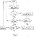
- FIG. 4is a flowchart illustrating this most preferred control scheme.
- the control schemeutilizes a garment temperature setpoint "T i " and an exhaust temperature setpoint "T o ".
- the control schemealso utilizes idealized time curves for both the garment temperature and the exhaust temperature over the course of the drying cycle. These are illustrated in FIG. 5. These values and curves are entered into a memory storage device, such as a microprocessor-based programmable controller that can be utilized for the previously noted controller 70.
- the controllerUpon entry of all setpoints and idealized curves, and initiation of the dryer operation, the controller executes a first control step in which the measured garment temperature T ir is compared to the garment temperature setpoint T i . Additionally, the measured dryer exhaust temperature T exh is compared to the exhaust setpoint T o . If the measured garment temperature T ir is greater than or equal to the garment temperature setpoint T i , or if the measured dryer exhaust temperature T exh is greater than or equal to the dryer exhaust temperature setpoint T o , then the control scheme reduces the flow of gas to the dryer heater. If however, the measured garment temperature T ir is less than the garment temperature setpoint T i , and the measured dryer exhaust temperature T exh is less than the dryer exhaust setpoint T o , then another comparison is performed.
- the rate of temperature increase of the measured garment temperaturei.e. T ir /time
- the rate of temperature increase of the measured dryer exhausti.e. T exh /time
- the slope of the idealized dryer exhaust temperature curve at the corresponding point in time in the drying cyclei.e. S o1 or S o2 .
- the totalized value of the measured garment temperature from the beginning of the dryer operation T ir * timeis compared to the integrated value or area under the idealized garment temperature curve from the beginning up to the particular point in time, such as A i1 or A i2 .
- the totalized value of the measured dryer exhaust temperature from the beginning of the dryer operation T exh * timeis compared to the area under the idealized dryer exhaust temperature curve up to that particular point in time, i.e. A o1 or A 02 . If either of the measured totalized values T ir * time or T exh * time, is greater than or equal to its corresponding A i or A o , the flow of gas to the dryer heater is reduced. If both the measured totalized values T ir * time and T exh * time are less than their corresponding A i or A o values, the control scheme then increases the flow of gas to the dryer heater.
- two infrared sensorsare utilized to measure garment temperature.
- the signals from the two infrared sensorscan be averaged or otherwise combined to provide the previously noted T ir signal.
- the present inventionalso provides control schemes for determining drying cycle completion.
- control schemes for determining drying cycle completionare two control strategies for dryer systems utilizing infrared sensors.
- a first technique for determining drying cycle completionis accomplished by comparing the rate of temperature increase of the garments being dried to one or more of the following: (i) a preset drying rate value, (ii) a drying rate value which is set according to current dryer load conditions, and/or to (iii) a previous drying rate of a similar dryer load or several past loads.
- the preset drying rate valuewould be entered into a storage device in association with the control system.
- the second type of valuei.e.
- a drying rate value which is set according to current dryer load conditionsis a value that is wholly or partially determined by the control system based upon characteristics of the current dryer load.
- the third type of valuei.e. a drying rate value determined by previous drying rates of previous loads, is wholly or partially determined by the control system using data archived from previous drying loads.
- This first technique for determining drying cycle completionis based upon the principle that if the introduction of heat to the dryer is constant, the temperature of the garments during the drying cycle increases at a greater rate once water retained in the garments being dried has been driven off since energy from the heat input no longer results in evaporation of moisture. Instead, the heat input causes an increase in the temperature of the garments. Such temperature increase is measured by the infrared sensor(s) according to the present invention. Once the rate of temperature increase, as measured by one, or more infrared sensing devices, reaches or exceeds one or more of the three previously described drying rate values (i) - (iii), dryer cycle completion or indication thereof would occur.
- a second technique for determining dryer cycle completionis to monitor garment temperature as indicated or measured by one or more infrared sensors 60. Once the measured garment temperature reaches or exceeds a preset temperature value, dryer cycle completion or indication thereof occurs. It is also contemplated that these control techniques could be employed together, or in combination with other control schemes.
- FIG. 6illustrates temperature readings measured in a first set of trials by temperature sensors disposed on inlet and outlet airstreams and a moisture probe during 12-1/2 minutes of a drying cycle. Accordingly, when heat was applied, the inlet temperature A rose and was maintained at the inlet temperature set point B. Similarly, exhaust air temperature C rose toward the exhaust temperature set point D. Although the actual garment temperatures measured by infrared sensors are not shown in FIG. 6, the exhaust air temperature C and actual garment temperatures rose in relative proportion to each other with a 40°F difference being the maximum variation between the two.
- the moisture probe Emeasured the amount of moisture in the exhaust air. As is evident from FIG. 6, the measured moisture level E initially rose, and then gradually decreased as the moisture was removed from the garments. When the moisture probe reached its set point F, the drying cycle ended.
- garment temperatureis represented proportionally by the exhaust air temperature C
- the actual difference between the garment temperature and the exhaust air temperaturevaried from 0 to 40°F.
- conventional dryness determinations based upon exhaust temperature, or humidity probes which are compensated by exhaust temperature measurementscan affect the dryness determination calculation by as much as 25 percent.
- moisture removal calculationscan be improved by about 25 percent by using the infrared temperature sensor(s) according to the present invention to determine actual garment temperature instead of employing exhaust temperature measurements that only provide an indication of garment temperature.
- FIG. 7compares prior art moisture removal calculations utilizing moisture probe readings A to calculations based upon actual garment temperatures measured by infrared sensors B. Calculations were based upon a drying trial performed in a commercial 400 pound dryer, drying 400 pounds of towels having an initial 65 percent water retention level. The dryer controls were set to 625°F inlet temperature and 220°F exhaust temperature.
- the dryer utilized in the testingcontained numerous sensors that provided input measurement values employed in calculating W and Q.
- the dryercomprised a temperature sensor at the flame in the dryer heater unit that provided a measurement of flame temperature, referred to as T in .
- the dryercomprised four temperature sensors located at opposite corners of the drying chamber which were averaged together to provide an average measurement of the temperature within the drying chamber, referred to herein as T avg .
- the dryeralso comprised an infrared sensor that provided a measurement of the temperature of garments as they dried, referred to herein as T ir .
- the dryeradditionally contained a temperature sensor at the dryer exhaust that provided a measurement of the temperature of air exiting the dryer, designated as T exh .
- the dryerfurther contained a humidity probe located within the drying chamber that provided a measurement of humidity or moisture level within the drying chamber.
- the dryeralso contained a measuring device on the gas line to the dryer heating line that measured the pressure of gas flowing to the burner. Also provided on the gas line was a device for measuring the amount, by volume, of gas flowing to the burner.
- Q actualwas determined by measuring the amount of gas actually supplied to the dryer heater.
- W actualwas determined by weighing the wet garments at the beginning of the dry cycle and the dried garments at the end of the cycle.
- Qwas determined three ways. In the first approach, Q was calculated utilizing T in for T 2 , and the ambient air temperature T amb for T 1 in the calculations for Q. In a second approach, Q was calculated utilizing T avg for T 2 and T amb for T 1 . In a third approach, Q was calculated based upon pressure readings of the gas flowing to the dryer heater.
- Wwas determined five different ways. In a first approach, W was calculated utilizing T in for T 1 and T exh for T 2 . Secondly, W was calculated using T avg for T 1 and T exh for T 2 . Thirdly, W was calculated by using T in for T 1 and T ir for T 2 . In the fourth approach, W was calculated by utilizing T avg for T 1 and T ir for T 2 . In the fifth approach, W was determined based upon measurements from a moisture probe. The Q actual /W actual and various other ratios of Q/W for each of the nine trials were then averaged, and are set forth in Table I below.
- Q/WAll values for Q/W in the table are expressed as BTU's per pound of water removed.
- Q/WBTU Used vs. Water Removed
- Average of Theoretical Methodsvs. Actual Average % deviation from Actual Q (based on T in ) Q (based on T avg ) Q (based on nozzle pressure) Q (actual) W i/exh (based on T in /T exh ) 1,830 1,478 1,012 3,966 54% 63% 74% W avg/exh (based on T avg /T exh ) 2,669 2,152 1,474 33% 46% 63% W i/ir (based on T in /T ir ) 2,364 1,908 1,305 40% 52% 67% W avg/ir (based on T avg /T ir ) 3,892 3,140 2,149 2% 21% 46% W moist (based on moist. probe) 1,927 1,553 1,061
Landscapes
- Engineering & Computer Science (AREA)
- Textile Engineering (AREA)
- Control Of Washing Machine And Dryer (AREA)
- Drying Of Solid Materials (AREA)
Abstract
Description
- CP
- is the specific heat of air (BTU/lb °R);
- T1
- is the temperature of air initially (prior to heatingby dryer) (°F);
- T2
- is the temperature of heated air (°F); and
- w
- is the specific humidity of air (lb H2O/lb dry air).
- h1
- is enthalpy of the system initially (BTU/lbdry air;
- Cp
- is the specific heat of air (BTU/lb °R);
- T2
- is the temperature of heated air (°F);
- Hvap
- is the average heat of vaporisation of waterover the range of drying temperatures (BTU/lbair);
- T1
- is the initial temperature of thedrying air (°F); and
- w1
- is the specific humidity of the dryingair initially (lb H2O/lb dry air).
| Q/W (BTU Used vs. Water Removed)Average of Theoretical Methods vs. Actual | ||||
| Average % deviation from Actual | Q (based on Tin) | Q (based on Tavg) | Q (based on nozzle pressure) | Q (actual) |
| W i/exh (based on Tin/Texh) | 1,830 | 1,478 | 1,012 | 3,966 |
| 54% | 63% | 74% | ||
| W avg/exh (based on Tavg/Texh) | 2,669 | 2,152 | 1,474 | |
| 33% | 46% | 63% | ||
| W i/ir (based on Tin/Tir) | 2,364 | 1,908 | 1,305 | |
| 40% | 52% | 67% | ||
| W avg/ir (based on Tavg/Tir) | 3,892 | 3,140 | 2,149 | |
| 2% | 21% | 46% | ||
| W moist (based on moist. probe) | 1,927 | 1,553 | 1,061 | |
| 51% | 61% | 73% | ||
| Note: The numbers presented in Table I (BTU/pound of water removed) include the BTU received from the air |
Claims (16)
- A rotatable drum dryer comprising:a dryer unit including a rotatable drum forreceiving and tumbling moist or wet articles to be dried, aheating device for heating said articles disposed in saiddrum, and a blower unit for passing air over said, articles insaid drum; andan infrared sensing device that provides ameasurement of the temperature of articles in said drum.
- The drum dryer of claim 1 wherein said infraredsensing device provides at least one control signalrepresentative of said temperature of said articles in saiddrum.
- The drum dryer of claim 2 wherein said at least onecontrol signal is an analog signal.
- The drum dryer of claim 2 wherein said at least onecontrol signal is a digital signal.
- The drum dryer of claim 1 wherein said infraredsensing device provides a visual indication of saidtemperature of said articles in said drum.
- The drum dryer of claim 1 wherein said infraredsensing device comprises an infrared sensor, said sensordisposed on said dryer approximately along the axis ofrotation of said drum.
- The drum dryer of claim 1 further comprising:a second infrared sensing device that provides ameasurement of the temperature of articles in said drum.
- The drum dryer of claim 7 wherein both said infraredsensing devices comprise infrared sensors, and both said sensors are disposed on said dryer at locations approximatelyalong the axis of rotation of said drum.
- A control system for governing the operation of adryer having a rotatable drum, a dryer air inlet, and a dryerair outlet, said control system comprising:a temperature sensor device exposed to air in oneof said dryer air outlet and said dryer air inlet, whereinsaid temperature sensor device provides a first controlsignal;at least one infrared sensor device having a viewof the interior of said drum, wherein said at least oneinfrared sensor device provides a second control signal; anda controller for governing the operation of saiddryer based upon at least said first and second controlsignals.
- The control system of claim 9 wherein said controlsystem comprises two infrared sensor devices and wherein saidtemperature sensor device is exposed to air in said dryer airoutlet.
- A method for determining drying cycle completion ina dryer having a rotatable drum for receiving and tumblingmoist or wet articles to be dried, a heating device forheating said articles disposed in said drum, and an infraredsensing device that provides a measurement of the temperatureof said articles in said drum, said method comprising:comparing the rate of temperature increase of saidarticles in said drum during drying with a value selected fromthe group consisting of (i) a predetermined drying rate value,(ii) a drying rate value determined according to current dryerload conditions, and (iii) a drying rate value determined,according to a previous dryer load.
- The method of claim 11 further comprising:performing at least one of (a) indicating dryercycle completion and (b) terminating said drying cycle, whensaid rate of temperature increase of said articles in saiddrum equals or exceeds at least one of said values (i), (ii),and (iii).
- A method for determining drying cycle completion ina dryer having a rotatable drum for receiving and tumblingmoist or wet articles to be dried, a heating device forheating said articles disposed in said drum, and an infraredsensing device that provides a measurement of the temperatureof said articles in said drum, said method comprising:comparing the temperature of said articles in saiddrum as measured by said infrared sensing device during dryeroperation to a preset temperature value.
- The method of claim 13 further comprising:performing at least one of (a) indicating dryercycle completion or (b) terminating said drying cycle, whensaid temperature of said articles in said drum equals orexceeds said preset temperature value.
- A method for controlling drying temperatures withina dryer, said dryer comprising (i) a plurality of temperaturesensors for measuring the temperature of air within saiddrying chamber, each said temperature sensor providing asignal representative of said temperature of said air withinsaid drying chamber designated as Ti, (ii) a flame temperaturesensor disposed proximate to a dryer heating unit formeasuring the temperature of a flame in said heating unit,said flame temperature sensor providing a signalrepresentative of said temperature of said flame designatedas Tin, (iii) an infrared sensor disposed proximate to saiddrying chamber for measuring the temperature of garments tobe dried in said drying chamber, said infrared sensorproviding a signal representative of said garment temperature designated as Tir, and (iv) a dryer heater unit, said methodcomprising:averaging at least two of said signals Ti to producea signal Tavg;determining heat input Q utilizing said signal Tin;determining weight amount of water removed Wutilizing said signals Tavg and Tir;determining a ratio of heat input per weight amountof water removed by dividing said Q by said W; andutilizing said ratio to regulate said dryer heaterunit.
- A method for controlling the temperature within adryer, said dryer comprising a drum for receiving and dryingarticles, a dryer exhaust, a dryer heater unit, a valve forregulating fuel to said dryer heater unit, a temperaturesensor providing a signal representative of said temperatureof said dryer exhaust Texh, and an infrared sensing deviceproviding a measurement of the temperature of articles in saiddrum Tir, said method comprising:(i) providing a garment temperature setpoint Ti and agarment temperature time curve;(ii) providing a dryer exhaust temperature setpoint Toand a dryer exhaust temperature time curve;(iii) comparing Ti to Tir and To to Texh;(iv) performing either (a) reducing said valve if Tir isequal or greater than Ti, or if Texh is equal or greater thanTo, or (b) proceeding to step (v) if Tir is less than Ti, andif Texh is less than To;(v) comparing the rate of change of Tir to the slope Siof said garment temperature time curve, and the rate of changeof Texh to the slope So of said dryer exhaust temperature timecurve;(vi) performing either (a) reducing said, valve if saidrate of change of Tir is equal or greater than Si, or if saidrate of change of Texh is equal or greater than So, or (b) proceeding to step (vii) if said rate of change of Tir is lessthan Si, and said rate of change of Texh is less than So;(vii) comparing the totalized Tir to the integrated valueAi of said garment temperature time curve, and the totalizedTexh to the integrated value Ao of said dryer exhausttemperature time curve;(viii) performing either (a) reducing said valve if saidtotalized Tir is equal or greater than Ai, or if said totalizedTexh is equal or greater than Ao, or (b) proceeding to step(ix) if said totalized Tir is less than Ai, and said totalizedTexh is less than Ao;(ix) increasing said valve; and(x) repeating steps (iii) - (ix) until said method isterminated.
Applications Claiming Priority (2)
| Application Number | Priority Date | Filing Date | Title |
|---|---|---|---|
| US08/674,025US5651192A (en) | 1996-07-01 | 1996-07-01 | Infrared temperature sensing for tumble drying control |
| US674025 | 1996-07-01 |
Publications (3)
| Publication Number | Publication Date |
|---|---|
| EP0816551A2true EP0816551A2 (en) | 1998-01-07 |
| EP0816551A3 EP0816551A3 (en) | 1998-10-21 |
| EP0816551B1 EP0816551B1 (en) | 2003-07-23 |
Family
ID=24705024
Family Applications (1)
| Application Number | Title | Priority Date | Filing Date |
|---|---|---|---|
| EP97109804AExpired - LifetimeEP0816551B1 (en) | 1996-07-01 | 1997-06-17 | Infrared temperature sensing for tumble drying control |
Country Status (5)
| Country | Link |
|---|---|
| US (2) | US5651192A (en) |
| EP (1) | EP0816551B1 (en) |
| JP (1) | JPH1096588A (en) |
| DE (1) | DE69723622T2 (en) |
| DK (1) | DK0816551T3 (en) |
Cited By (7)
| Publication number | Priority date | Publication date | Assignee | Title |
|---|---|---|---|---|
| US20110063101A1 (en)* | 2009-09-17 | 2011-03-17 | Michael Cristoforo | Carbon Monoxide Safety System And Method |
| US8782922B2 (en) | 2010-11-24 | 2014-07-22 | Ecolab Usa Inc. | Dryer monitoring |
| US8819958B2 (en) | 2010-11-08 | 2014-09-02 | Whirlpool Corporation | End of cycle detection for a laundry treating appliance |
| US9206543B2 (en) | 2011-10-14 | 2015-12-08 | Ecolab Usa Inc. | Dryer monitoring |
| US9249539B2 (en) | 2006-09-25 | 2016-02-02 | Ecolab Inc. | Determination of dryness of textiles in a dryer |
| DE102017223324A1 (en) | 2017-12-20 | 2019-06-27 | BSH Hausgeräte GmbH | Method for operating a water-conducting household appliance with a spectrometer and suitable household appliance |
| US12098496B2 (en) | 2020-06-19 | 2024-09-24 | Ecolab Usa Inc. | Embedded temperature sensors for monitoring temperature of articles and status of drying or cleaning cycles |
Families Citing this family (75)
| Publication number | Priority date | Publication date | Assignee | Title |
|---|---|---|---|---|
| AU6027798A (en)* | 1997-01-17 | 1998-08-07 | John W. Tidland | Roasting system with heat recycler |
| US20070151312A1 (en)* | 2005-12-30 | 2007-07-05 | Bruce Beihoff C | Modular fabric revitalizing system |
| US8844160B2 (en) | 1997-04-29 | 2014-09-30 | Whirlpool Corporation | Modular fabric revitalizing system |
| DE19741160A1 (en)* | 1997-09-18 | 1999-03-25 | Bosch Siemens Hausgeraete | Detecting disturbances in electronically controlled dryers |
| US6026592A (en)* | 1998-05-13 | 2000-02-22 | Maytag Corporation | Drying rack with electronic control |
| US6986279B2 (en)* | 2000-08-22 | 2006-01-17 | Barnstead Thermolyne Corporation | Method and apparatus for determining liquid absorption of aggregate |
| US6486475B1 (en) | 2000-08-22 | 2002-11-26 | Barnstead-Thermolyne Corporation | Method and apparatus for determining liquid absorption of aggregate |
| DE10134971A1 (en)* | 2001-07-24 | 2003-02-06 | Kannegiesser H Gmbh Co | Process for drying laundry |
| US6505418B1 (en)* | 2001-08-15 | 2003-01-14 | American Dryer Corporation | Apparatus and method for a clothing dryer having a fire protection system |
| CA2390660C (en)* | 2002-06-13 | 2007-10-16 | Camco Inc. | Control system for an automatic clothes dryer |
| US20050086826A1 (en)* | 2003-06-04 | 2005-04-28 | Frushtick Jeffrey N. | Tunnel finisher with infrared feedback temperature control |
| US6715216B1 (en) | 2003-07-11 | 2004-04-06 | Cissell Manufacturing Company | Clothes dryer with fire suppression system |
| EP1577433B2 (en)* | 2004-02-17 | 2015-11-25 | LG Electronics, Inc. | Operation control method for a drum type washing machine |
| US20060130243A1 (en)* | 2004-12-17 | 2006-06-22 | Maytag Corporation | Continuous laundry cleaning appliance |
| US7082695B1 (en)* | 2005-01-24 | 2006-08-01 | King-Leung Wong | Power-saving drying machine control |
| ES2279674B1 (en)* | 2005-03-23 | 2008-08-01 | Ibai, S. Coop. | CLOTHING AND DRYING CLOTHING CLOTHING. |
| CA2505565C (en) | 2005-04-28 | 2008-09-16 | Camco Inc. | Apparatus and method for controlling a clothes dryer |
| CA2508860C (en) | 2005-05-30 | 2007-10-16 | Camco Inc. | Clothes dryer reversible door assembly |
| CA2508607C (en)* | 2005-05-30 | 2007-09-11 | Camco Inc. | Clothes dryer door assembly |
| US7845197B2 (en)* | 2005-05-31 | 2010-12-07 | Leonard Automatics, Inc. | Triple pass tunnel finisher with an articulated spraying function |
| US7845037B2 (en)* | 2005-05-31 | 2010-12-07 | Leonard Automatics, Inc. | Triple pass tunnel finisher |
| DE102005055411A1 (en)* | 2005-11-21 | 2007-05-24 | Robert Bosch Gmbh | Dryers and processes using the dryer |
| US7921578B2 (en)* | 2005-12-30 | 2011-04-12 | Whirlpool Corporation | Nebulizer system for a fabric treatment appliance |
| US7665227B2 (en) | 2005-12-30 | 2010-02-23 | Whirlpool Corporation | Fabric revitalizing method using low absorbency pads |
| US7735345B2 (en) | 2005-12-30 | 2010-06-15 | Whirlpool Corporation | Automatic fabric treatment appliance with a manual fabric treatment station |
| KR101270860B1 (en)* | 2006-05-26 | 2013-06-05 | 엘지전자 주식회사 | Drying method of a laundry room machine |
| DE102006025952A1 (en)* | 2006-06-02 | 2007-12-06 | BSH Bosch und Siemens Hausgeräte GmbH | A method for detecting the stoppage of a drum in a drum dryer, and suitable drum dryer for this purpose |
| US8065815B2 (en)* | 2006-10-10 | 2011-11-29 | Rdp Technologies, Inc. | Apparatus, method and system for treating sewage sludge |
| DE102006053274A1 (en)* | 2006-11-06 | 2008-05-08 | E.G.O. Elektro-Gerätebau GmbH | Method for determining the amount of charge in a tumble dryer and tumble dryer |
| ATE498727T1 (en) | 2007-08-14 | 2011-03-15 | Bsh Bosch Siemens Hausgeraete | METHOD FOR DETECTING VOLATILE, FLAMMABLE SUBSTANCES IN A DRYER AND SUITABLE DRYER FOR THIS |
| DE102007038369A1 (en) | 2007-08-14 | 2009-02-19 | BSH Bosch und Siemens Hausgeräte GmbH | Volatile, inflammable substances e.g. alcohol, detecting method for use in condensation laundry dryer of washing machine, involves receiving infrared-radiation by receiving element in wave number scale between specific range |
| DE102007041066A1 (en) | 2007-08-30 | 2009-03-05 | BSH Bosch und Siemens Hausgeräte GmbH | Method for detecting volatile and flammable substances, involves drying of water-wet textiles in dryer, which is provided with drum for receiving textiles |
| DE102007059516A1 (en)* | 2007-12-11 | 2009-06-18 | BSH Bosch und Siemens Hausgeräte GmbH | Method for drying time control in dishwashers |
| CN101970747B (en)* | 2008-03-13 | 2012-09-12 | 松下电器产业株式会社 | Clothes drying control method and clothes dryer |
| US8726535B2 (en)* | 2008-12-16 | 2014-05-20 | Pioneer Hi Bred International Inc | Method, apparatus and system for controlling heated air drying |
| US8832966B2 (en)* | 2009-02-19 | 2014-09-16 | Whirpool Corporation | Laundry treating appliance with fluffing-state detection |
| US8528228B2 (en)* | 2009-02-19 | 2013-09-10 | Whirlpool Corporation | Laundry treating appliance with drying rack detection based on imaging data |
| US8528230B2 (en)* | 2009-02-19 | 2013-09-10 | Whirlpool Corporation | Laundry treating appliance with bulky item detection |
| US8528229B2 (en) | 2009-02-19 | 2013-09-10 | Whirlpool Corporation | Laundry treating appliance with imaging control |
| US8522452B2 (en)* | 2009-02-19 | 2013-09-03 | Whirlpool Corporation | Laundry treating appliance with state of dryness based imaging control |
| US9745688B2 (en) | 2009-02-19 | 2017-08-29 | Whirlpool Corporation | Laundry treating appliance with load surface area detection |
| US9580860B2 (en)* | 2009-12-18 | 2017-02-28 | Whirlpool Corporation | Method for operating a clothes dryer using load temperature determined by an infrared sensor |
| US8549770B2 (en) | 2009-12-18 | 2013-10-08 | Whirlpool Corporation | Apparatus and method of drying laundry with drying uniformity determination |
| US8245415B2 (en) | 2009-12-18 | 2012-08-21 | Whirlpool Corporation | Method for determining load size in a clothes dryer using an infrared sensor |
| JP5382056B2 (en)* | 2011-04-22 | 2014-01-08 | パナソニック株式会社 | Dehumidifier |
| US8561320B2 (en)* | 2011-08-31 | 2013-10-22 | General Electric Company | System and method for determining status of a drying cycle and for controlling a dryer |
| CN104053953B (en)* | 2012-01-31 | 2017-08-29 | 三菱电机株式会社 | Dehumidifier |
| DE102012008193A1 (en)* | 2012-04-26 | 2013-10-31 | Herbert Kannegiesser Gmbh | Method for drying laundry items |
| WO2014148159A1 (en)* | 2013-03-19 | 2014-09-25 | 三菱電機株式会社 | Dehumidifier |
| DE102013205311A1 (en) | 2013-03-26 | 2014-10-02 | BSH Bosch und Siemens Hausgeräte GmbH | Method for measuring heat radiation in a rotating laundry drum, and machine for carrying out such a method |
| US9371609B2 (en)* | 2014-06-24 | 2016-06-21 | General Electric Company | Dryer appliances and methods for operating same |
| DE102014218254A1 (en)* | 2014-09-11 | 2016-03-17 | BSH Hausgeräte GmbH | Condensation dryer with a temperature sensor, and method of its operation |
| KR102290758B1 (en)* | 2014-09-29 | 2021-08-18 | 엘지전자 주식회사 | Control Method of Laundry Treating Apparatus |
| KR102214069B1 (en) | 2014-09-29 | 2021-02-09 | 엘지전자 주식회사 | Steam Generator and Laundry Treating Apparatus having the same |
| DE102016205756A1 (en) | 2016-04-07 | 2017-10-12 | BSH Hausgeräte GmbH | Method for improved control of a water-conducting household appliance and suitable household appliance |
| DE102016210169A1 (en) | 2016-06-09 | 2017-12-14 | BSH Hausgeräte GmbH | Method for improved control of a water-conducting household appliance and suitable household appliance |
| DE102016211328A1 (en) | 2016-06-24 | 2017-12-28 | BSH Hausgeräte GmbH | Method for improved control of a water-conducting household appliance and suitable household appliance |
| US10260194B2 (en)* | 2016-07-15 | 2019-04-16 | Whirlpool Corporation | Laundry treating appliance with a sensor |
| CN106854827B (en)* | 2016-08-29 | 2020-11-03 | 青岛海尔滚筒洗衣机有限公司 | Clothes dryer trunk judging method |
| CN108004733B (en)* | 2016-10-31 | 2020-04-17 | 众智光电科技股份有限公司 | Clothes dryer |
| DE102016222095A1 (en) | 2016-11-10 | 2018-05-17 | BSH Hausgeräte GmbH | Method for improved control of a water-conducting household appliance and suitable household appliance |
| JP2018175728A (en)* | 2017-04-20 | 2018-11-15 | パナソニックIpマネジメント株式会社 | Hair dryer |
| DE102017209135A1 (en) | 2017-05-31 | 2018-12-06 | BSH Hausgeräte GmbH | Method for controlling a water-conducting household appliance and suitable household appliance |
| DE102017215132A1 (en) | 2017-08-30 | 2019-02-28 | BSH Hausgeräte GmbH | Laundry treatment apparatus with spectrometer and improved filtration device and method of operation |
| AU2018412043B2 (en)* | 2018-03-07 | 2024-08-29 | Electrolux Appliances Aktiebolag | Laundry appliance with user sensing functionality |
| NL2020825B1 (en)* | 2018-04-25 | 2019-11-05 | Technisch Bureau Reinders B V | Installation and method for drying laundry |
| KR102661827B1 (en)* | 2018-10-30 | 2024-04-26 | 엘지전자 주식회사 | A Laundry Apparatus |
| CN110075327A (en)* | 2019-04-28 | 2019-08-02 | 杭州老板电器股份有限公司 | The control method of disinfection cabinet and disinfection cabinet |
| CN110629484B (en)* | 2019-09-17 | 2021-09-21 | 无锡小天鹅电器有限公司 | Frame assembly of clothes treatment device and clothes treatment device |
| KR102813614B1 (en)* | 2019-10-18 | 2025-05-29 | 엘지전자 주식회사 | Integrated laundry processing apparatus, and method for controlling the same |
| CN115968418A (en)* | 2020-06-24 | 2023-04-14 | Lg电子株式会社 | Clothes treating apparatus |
| KR20220169750A (en)* | 2021-06-21 | 2022-12-28 | 엘지전자 주식회사 | Laundry Treatment Apparatus and Controlling Method for the same |
| US12405058B2 (en)* | 2021-08-16 | 2025-09-02 | Stolle Machinery Company, Llc | Can drying and moisture control system |
| CN114383411B (en)* | 2021-12-06 | 2023-04-18 | 广东智科电子股份有限公司 | Heat pump drying control method, device and system and storage medium |
| CN117781620B (en)* | 2024-02-23 | 2024-04-26 | 临朐天利生物制品有限公司 | Pagodatree flower bud drying system |
Family Cites Families (18)
| Publication number | Priority date | Publication date | Assignee | Title |
|---|---|---|---|---|
| US3116982A (en)* | 1959-05-19 | 1964-01-07 | Energy Kontrols Inc | Humidity responsive drying apparatus |
| US3583688A (en)* | 1960-09-09 | 1971-06-08 | Whirlpool Co | Dryer control |
| JPS5759850Y2 (en)* | 1978-07-13 | 1982-12-21 | ||
| GB2038039B (en)* | 1978-12-11 | 1983-08-17 | Matsushita Electric Industrial Co Ltd | Automatic temperature control of water heater |
| GB8602510D0 (en)* | 1986-02-01 | 1986-03-05 | Waddingtons Ltd | Coating of web materials |
| DE3639929A1 (en)* | 1986-11-22 | 1988-06-01 | Babcock Bsh Ag | CONTINUOUS DRYER FOR VENEER BLADES |
| SE461560B (en)* | 1988-02-24 | 1990-02-26 | Carl Goesta Ardesjoe | DEVICE FOR MONITORING OF OBJECTS, SUCH AS COOKING PLATE AND ELECTRIC OVEN, WITH REGARD TO OVERHEATING |
| US5135122A (en)* | 1989-01-03 | 1992-08-04 | The J. M. Smucker Company | Method and apparatus for dehydrating fruit |
| JPH05200194A (en)* | 1991-11-18 | 1993-08-10 | Matsushita Electric Ind Co Ltd | Clothes dryer control device |
| KR940006250B1 (en)* | 1991-12-23 | 1994-07-13 | 주식회사 금성사 | Drying control method and circuit of complex sensor type |
| US5351417A (en)* | 1992-09-22 | 1994-10-04 | Secajo, Ltd. | Hair dryer apparatus adapted for multi-functional usage |
| JPH06126099A (en)* | 1992-10-19 | 1994-05-10 | Sharp Corp | Clothes dryer |
| IL107409A (en)* | 1992-10-30 | 1999-03-12 | Gen Electric | Appliance electronic control system with programmable parameters including programmable and reconfigurable fuzzy logic controller |
| US5405475A (en)* | 1993-05-28 | 1995-04-11 | Ward/Kraft | Method and apparatus for continuous manufacture of printed laminated stock from uncoated web |
| JPH078691A (en)* | 1993-06-24 | 1995-01-13 | Toshiba Corp | Clothes dryer |
| JPH07178293A (en)* | 1993-12-24 | 1995-07-18 | Matsushita Electric Ind Co Ltd | Dryer |
| JP3022150B2 (en)* | 1994-04-27 | 2000-03-15 | 三洋電機株式会社 | Clothes dryer |
| US5396715A (en)* | 1994-06-09 | 1995-03-14 | Electric Power Research Institute | Microwave clothes dryer and method with fire protection |
- 1996
- 1996-07-01USUS08/674,025patent/US5651192A/ennot_activeExpired - Fee Related
- 1997
- 1997-04-28USUS08/848,140patent/US5755041A/ennot_activeExpired - Fee Related
- 1997-06-17EPEP97109804Apatent/EP0816551B1/ennot_activeExpired - Lifetime
- 1997-06-17DKDK97109804Tpatent/DK0816551T3/enactive
- 1997-06-17JPJP9160280Apatent/JPH1096588A/ennot_activeWithdrawn
- 1997-06-17DEDE69723622Tpatent/DE69723622T2/ennot_activeExpired - Fee Related
Cited By (8)
| Publication number | Priority date | Publication date | Assignee | Title |
|---|---|---|---|---|
| US9249539B2 (en) | 2006-09-25 | 2016-02-02 | Ecolab Inc. | Determination of dryness of textiles in a dryer |
| US20110063101A1 (en)* | 2009-09-17 | 2011-03-17 | Michael Cristoforo | Carbon Monoxide Safety System And Method |
| US8819958B2 (en) | 2010-11-08 | 2014-09-02 | Whirlpool Corporation | End of cycle detection for a laundry treating appliance |
| US8782922B2 (en) | 2010-11-24 | 2014-07-22 | Ecolab Usa Inc. | Dryer monitoring |
| US9206543B2 (en) | 2011-10-14 | 2015-12-08 | Ecolab Usa Inc. | Dryer monitoring |
| US9850621B2 (en) | 2011-10-14 | 2017-12-26 | Ecolab Usa Inc. | Dryer monitoring |
| DE102017223324A1 (en) | 2017-12-20 | 2019-06-27 | BSH Hausgeräte GmbH | Method for operating a water-conducting household appliance with a spectrometer and suitable household appliance |
| US12098496B2 (en) | 2020-06-19 | 2024-09-24 | Ecolab Usa Inc. | Embedded temperature sensors for monitoring temperature of articles and status of drying or cleaning cycles |
Also Published As
| Publication number | Publication date |
|---|---|
| US5651192A (en) | 1997-07-29 |
| EP0816551A3 (en) | 1998-10-21 |
| DE69723622D1 (en) | 2003-08-28 |
| DE69723622T2 (en) | 2004-06-09 |
| DK0816551T3 (en) | 2003-11-03 |
| US5755041A (en) | 1998-05-26 |
| JPH1096588A (en) | 1998-04-14 |
| EP0816551B1 (en) | 2003-07-23 |
Similar Documents
| Publication | Publication Date | Title |
|---|---|---|
| EP0816551B1 (en) | Infrared temperature sensing for tumble drying control | |
| US4827627A (en) | Apparatus and method for controlling a drying cycle of a clothes dryer | |
| KR100664289B1 (en) | Drying method of the clothes dryer | |
| US7594343B2 (en) | Drying mode for automatic clothes dryer | |
| US6199300B1 (en) | Method for energy efficient control of a dryer of clothes | |
| US6158148A (en) | Method for detecting impermissible operating states in a hot-air clothes dryer, and a dryer with such a detection method | |
| US8112902B2 (en) | Method for determining the load quantity in a spin dryer and spin dryer | |
| CN101903587B (en) | Laundry drying device with moisture determination device and method for operating the laundry drying device | |
| KR880005429A (en) | Continuous Drying Monitoring System and Supervisory Control Method Using the Same | |
| US7080464B1 (en) | Detection of synthetic fabric loads in an automatic dryer | |
| AU2011335133B2 (en) | A method of controlling a rotatable-drum laundry drier and a rotatable-drum laundry drier implementing the method | |
| KR101683122B1 (en) | dryer | |
| US20080184588A1 (en) | Auto coin | |
| EP0060698B1 (en) | Improvements in or relating to tumble dryers | |
| EP2441880B1 (en) | Method for drying clothes in a drier and a moisture estimation control to obtain an automatic cycle termination | |
| CN116949776A (en) | Method for determining the final remaining humidity in a heat pump dryer and heat pump dryer | |
| JPS59232082A (en) | Tobacco leaf drying method and apparatus | |
| CN112130601A (en) | Humidity control method and device for test chamber, electronic equipment and storage medium | |
| EP4212664B1 (en) | Dryer with a heat pump and a water container comprising an electrode and process for its operation | |
| US20240117550A1 (en) | Systems and methods for operating a laundry treatment appliance to detect erroneous moisture levels | |
| JPH0411675Y2 (en) | ||
| JPH04327783A (en) | Test drier and method for controlling the same | |
| JPH0411674Y2 (en) | ||
| JPH0556757B2 (en) | ||
| JP2598800B2 (en) | Clothes dryer |
Legal Events
| Date | Code | Title | Description |
|---|---|---|---|
| PUAI | Public reference made under article 153(3) epc to a published international application that has entered the european phase | Free format text:ORIGINAL CODE: 0009012 | |
| AK | Designated contracting states | Kind code of ref document:A2 Designated state(s):DE DK FR GB IT NL SE | |
| PUAL | Search report despatched | Free format text:ORIGINAL CODE: 0009013 | |
| AK | Designated contracting states | Kind code of ref document:A3 Designated state(s):AT BE CH DE DK ES FI FR GB GR IE IT LU MC NL PT SE | |
| 17P | Request for examination filed | Effective date:19990409 | |
| AKX | Designation fees paid | Free format text:DE DK FR GB IT NL SE | |
| 17Q | First examination report despatched | Effective date:20000407 | |
| GRAH | Despatch of communication of intention to grant a patent | Free format text:ORIGINAL CODE: EPIDOS IGRA | |
| GRAH | Despatch of communication of intention to grant a patent | Free format text:ORIGINAL CODE: EPIDOS IGRA | |
| GRAA | (expected) grant | Free format text:ORIGINAL CODE: 0009210 | |
| AK | Designated contracting states | Designated state(s):DE DK FR GB IT NL SE | |
| REG | Reference to a national code | Ref country code:GB Ref legal event code:FG4D | |
| REF | Corresponds to: | Ref document number:69723622 Country of ref document:DE Date of ref document:20030828 Kind code of ref document:P | |
| REG | Reference to a national code | Ref country code:DK Ref legal event code:T3 | |
| REG | Reference to a national code | Ref country code:SE Ref legal event code:TRGR | |
| ET | Fr: translation filed | ||
| PLBE | No opposition filed within time limit | Free format text:ORIGINAL CODE: 0009261 | |
| STAA | Information on the status of an ep patent application or granted ep patent | Free format text:STATUS: NO OPPOSITION FILED WITHIN TIME LIMIT | |
| 26N | No opposition filed | Effective date:20040426 | |
| REG | Reference to a national code | Ref country code:GB Ref legal event code:732E | |
| NLS | Nl: assignments of ep-patents | Owner name:WASHEX LLP | |
| PGFP | Annual fee paid to national office [announced via postgrant information from national office to epo] | Ref country code:FR Payment date:20050512 Year of fee payment:9 | |
| PGFP | Annual fee paid to national office [announced via postgrant information from national office to epo] | Ref country code:GB Payment date:20050516 Year of fee payment:9 | |
| PGFP | Annual fee paid to national office [announced via postgrant information from national office to epo] | Ref country code:NL Payment date:20050517 Year of fee payment:9 | |
| PGFP | Annual fee paid to national office [announced via postgrant information from national office to epo] | Ref country code:DK Payment date:20050518 Year of fee payment:9 | |
| PGFP | Annual fee paid to national office [announced via postgrant information from national office to epo] | Ref country code:SE Payment date:20050519 Year of fee payment:9 | |
| PGFP | Annual fee paid to national office [announced via postgrant information from national office to epo] | Ref country code:DE Payment date:20050520 Year of fee payment:9 | |
| REG | Reference to a national code | Ref country code:FR Ref legal event code:TP | |
| PG25 | Lapsed in a contracting state [announced via postgrant information from national office to epo] | Ref country code:GB Free format text:LAPSE BECAUSE OF NON-PAYMENT OF DUE FEES Effective date:20060617 | |
| PG25 | Lapsed in a contracting state [announced via postgrant information from national office to epo] | Ref country code:SE Free format text:LAPSE BECAUSE OF NON-PAYMENT OF DUE FEES Effective date:20060618 | |
| PG25 | Lapsed in a contracting state [announced via postgrant information from national office to epo] | Ref country code:DK Free format text:LAPSE BECAUSE OF NON-PAYMENT OF DUE FEES Effective date:20060630 | |
| PGFP | Annual fee paid to national office [announced via postgrant information from national office to epo] | Ref country code:IT Payment date:20060630 Year of fee payment:10 | |
| PG25 | Lapsed in a contracting state [announced via postgrant information from national office to epo] | Ref country code:NL Free format text:LAPSE BECAUSE OF NON-PAYMENT OF DUE FEES Effective date:20070101 | |
| PG25 | Lapsed in a contracting state [announced via postgrant information from national office to epo] | Ref country code:DE Free format text:LAPSE BECAUSE OF NON-PAYMENT OF DUE FEES Effective date:20070103 | |
| REG | Reference to a national code | Ref country code:DK Ref legal event code:EBP | |
| EUG | Se: european patent has lapsed | ||
| GBPC | Gb: european patent ceased through non-payment of renewal fee | Effective date:20060617 | |
| NLV4 | Nl: lapsed or anulled due to non-payment of the annual fee | Effective date:20070101 | |
| REG | Reference to a national code | Ref country code:FR Ref legal event code:ST Effective date:20070228 | |
| PG25 | Lapsed in a contracting state [announced via postgrant information from national office to epo] | Ref country code:FR Free format text:LAPSE BECAUSE OF NON-PAYMENT OF DUE FEES Effective date:20060630 | |
| PG25 | Lapsed in a contracting state [announced via postgrant information from national office to epo] | Ref country code:IT Free format text:LAPSE BECAUSE OF NON-PAYMENT OF DUE FEES Effective date:20070617 |