EP0816423B1 - Thermally conductive polytetrafluoroethylene article - Google Patents
Thermally conductive polytetrafluoroethylene articleDownload PDFInfo
- Publication number
- EP0816423B1 EP0816423B1EP97304490AEP97304490AEP0816423B1EP 0816423 B1EP0816423 B1EP 0816423B1EP 97304490 AEP97304490 AEP 97304490AEP 97304490 AEP97304490 AEP 97304490AEP 0816423 B1EP0816423 B1EP 0816423B1
- Authority
- EP
- European Patent Office
- Prior art keywords
- thermally conductive
- article
- ptfe
- present
- particles
- Prior art date
- Legal status (The legal status is an assumption and is not a legal conclusion. Google has not performed a legal analysis and makes no representation as to the accuracy of the status listed.)
- Expired - Lifetime
Links
Images


Classifications
- C—CHEMISTRY; METALLURGY
- C08—ORGANIC MACROMOLECULAR COMPOUNDS; THEIR PREPARATION OR CHEMICAL WORKING-UP; COMPOSITIONS BASED THEREON
- C08J—WORKING-UP; GENERAL PROCESSES OF COMPOUNDING; AFTER-TREATMENT NOT COVERED BY SUBCLASSES C08B, C08C, C08F, C08G or C08H
- C08J5/00—Manufacture of articles or shaped materials containing macromolecular substances
- H—ELECTRICITY
- H01—ELECTRIC ELEMENTS
- H01L—SEMICONDUCTOR DEVICES NOT COVERED BY CLASS H10
- H01L23/00—Details of semiconductor or other solid state devices
- H01L23/34—Arrangements for cooling, heating, ventilating or temperature compensation ; Temperature sensing arrangements
- H01L23/36—Selection of materials, or shaping, to facilitate cooling or heating, e.g. heatsinks
- H01L23/373—Cooling facilitated by selection of materials for the device or materials for thermal expansion adaptation, e.g. carbon
- H01L23/3737—Organic materials with or without a thermoconductive filler
- C—CHEMISTRY; METALLURGY
- C08—ORGANIC MACROMOLECULAR COMPOUNDS; THEIR PREPARATION OR CHEMICAL WORKING-UP; COMPOSITIONS BASED THEREON
- C08K—Use of inorganic or non-macromolecular organic substances as compounding ingredients
- C08K3/00—Use of inorganic substances as compounding ingredients
- C08K3/01—Use of inorganic substances as compounding ingredients characterized by their specific function
- C—CHEMISTRY; METALLURGY
- C08—ORGANIC MACROMOLECULAR COMPOUNDS; THEIR PREPARATION OR CHEMICAL WORKING-UP; COMPOSITIONS BASED THEREON
- C08K—Use of inorganic or non-macromolecular organic substances as compounding ingredients
- C08K9/00—Use of pretreated ingredients
- C08K9/02—Ingredients treated with inorganic substances
- C—CHEMISTRY; METALLURGY
- C08—ORGANIC MACROMOLECULAR COMPOUNDS; THEIR PREPARATION OR CHEMICAL WORKING-UP; COMPOSITIONS BASED THEREON
- C08J—WORKING-UP; GENERAL PROCESSES OF COMPOUNDING; AFTER-TREATMENT NOT COVERED BY SUBCLASSES C08B, C08C, C08F, C08G or C08H
- C08J2300/00—Characterised by the use of unspecified polymers
- C08J2300/22—Thermoplastic resins
- C—CHEMISTRY; METALLURGY
- C08—ORGANIC MACROMOLECULAR COMPOUNDS; THEIR PREPARATION OR CHEMICAL WORKING-UP; COMPOSITIONS BASED THEREON
- C08J—WORKING-UP; GENERAL PROCESSES OF COMPOUNDING; AFTER-TREATMENT NOT COVERED BY SUBCLASSES C08B, C08C, C08F, C08G or C08H
- C08J2327/00—Characterised by the use of homopolymers or copolymers of compounds having one or more unsaturated aliphatic radicals, each having only one carbon-to-carbon double bond, and at least one being terminated by a halogen; Derivatives of such polymers
- C08J2327/02—Characterised by the use of homopolymers or copolymers of compounds having one or more unsaturated aliphatic radicals, each having only one carbon-to-carbon double bond, and at least one being terminated by a halogen; Derivatives of such polymers not modified by chemical after-treatment
- C08J2327/12—Characterised by the use of homopolymers or copolymers of compounds having one or more unsaturated aliphatic radicals, each having only one carbon-to-carbon double bond, and at least one being terminated by a halogen; Derivatives of such polymers not modified by chemical after-treatment containing fluorine atoms
- C08J2327/18—Homopolymers or copolymers of tetrafluoroethylene
- C—CHEMISTRY; METALLURGY
- C08—ORGANIC MACROMOLECULAR COMPOUNDS; THEIR PREPARATION OR CHEMICAL WORKING-UP; COMPOSITIONS BASED THEREON
- C08J—WORKING-UP; GENERAL PROCESSES OF COMPOUNDING; AFTER-TREATMENT NOT COVERED BY SUBCLASSES C08B, C08C, C08F, C08G or C08H
- C08J2483/00—Characterised by the use of macromolecular compounds obtained by reactions forming in the main chain of the macromolecule a linkage containing silicon with or without sulfur, nitrogen, oxygen, or carbon only; Derivatives of such polymers
- C—CHEMISTRY; METALLURGY
- C08—ORGANIC MACROMOLECULAR COMPOUNDS; THEIR PREPARATION OR CHEMICAL WORKING-UP; COMPOSITIONS BASED THEREON
- C08L—COMPOSITIONS OF MACROMOLECULAR COMPOUNDS
- C08L27/00—Compositions of homopolymers or copolymers of compounds having one or more unsaturated aliphatic radicals, each having only one carbon-to-carbon double bond, and at least one being terminated by a halogen; Compositions of derivatives of such polymers
- C08L27/02—Compositions of homopolymers or copolymers of compounds having one or more unsaturated aliphatic radicals, each having only one carbon-to-carbon double bond, and at least one being terminated by a halogen; Compositions of derivatives of such polymers not modified by chemical after-treatment
- C08L27/12—Compositions of homopolymers or copolymers of compounds having one or more unsaturated aliphatic radicals, each having only one carbon-to-carbon double bond, and at least one being terminated by a halogen; Compositions of derivatives of such polymers not modified by chemical after-treatment containing fluorine atoms
- C08L27/18—Homopolymers or copolymers or tetrafluoroethene
- C—CHEMISTRY; METALLURGY
- C08—ORGANIC MACROMOLECULAR COMPOUNDS; THEIR PREPARATION OR CHEMICAL WORKING-UP; COMPOSITIONS BASED THEREON
- C08L—COMPOSITIONS OF MACROMOLECULAR COMPOUNDS
- C08L83/00—Compositions of macromolecular compounds obtained by reactions forming in the main chain of the macromolecule a linkage containing silicon with or without sulfur, nitrogen, oxygen or carbon only; Compositions of derivatives of such polymers
- H—ELECTRICITY
- H01—ELECTRIC ELEMENTS
- H01L—SEMICONDUCTOR DEVICES NOT COVERED BY CLASS H10
- H01L2224/00—Indexing scheme for arrangements for connecting or disconnecting semiconductor or solid-state bodies and methods related thereto as covered by H01L24/00
- H01L2224/01—Means for bonding being attached to, or being formed on, the surface to be connected, e.g. chip-to-package, die-attach, "first-level" interconnects; Manufacturing methods related thereto
- H01L2224/26—Layer connectors, e.g. plate connectors, solder or adhesive layers; Manufacturing methods related thereto
- H01L2224/31—Structure, shape, material or disposition of the layer connectors after the connecting process
- H01L2224/32—Structure, shape, material or disposition of the layer connectors after the connecting process of an individual layer connector
- H01L2224/321—Disposition
- H01L2224/32151—Disposition the layer connector connecting between a semiconductor or solid-state body and an item not being a semiconductor or solid-state body, e.g. chip-to-substrate, chip-to-passive
- H01L2224/32221—Disposition the layer connector connecting between a semiconductor or solid-state body and an item not being a semiconductor or solid-state body, e.g. chip-to-substrate, chip-to-passive the body and the item being stacked
- H01L2224/32245—Disposition the layer connector connecting between a semiconductor or solid-state body and an item not being a semiconductor or solid-state body, e.g. chip-to-substrate, chip-to-passive the body and the item being stacked the item being metallic
- H—ELECTRICITY
- H01—ELECTRIC ELEMENTS
- H01L—SEMICONDUCTOR DEVICES NOT COVERED BY CLASS H10
- H01L2924/00—Indexing scheme for arrangements or methods for connecting or disconnecting semiconductor or solid-state bodies as covered by H01L24/00
- H01L2924/095—Indexing scheme for arrangements or methods for connecting or disconnecting semiconductor or solid-state bodies as covered by H01L24/00 with a principal constituent of the material being a combination of two or more materials provided in the groups H01L2924/013 - H01L2924/0715
- H01L2924/097—Glass-ceramics, e.g. devitrified glass
- H01L2924/09701—Low temperature co-fired ceramic [LTCC]
- Y—GENERAL TAGGING OF NEW TECHNOLOGICAL DEVELOPMENTS; GENERAL TAGGING OF CROSS-SECTIONAL TECHNOLOGIES SPANNING OVER SEVERAL SECTIONS OF THE IPC; TECHNICAL SUBJECTS COVERED BY FORMER USPC CROSS-REFERENCE ART COLLECTIONS [XRACs] AND DIGESTS
- Y10—TECHNICAL SUBJECTS COVERED BY FORMER USPC
- Y10S—TECHNICAL SUBJECTS COVERED BY FORMER USPC CROSS-REFERENCE ART COLLECTIONS [XRACs] AND DIGESTS
- Y10S428/00—Stock material or miscellaneous articles
- Y10S428/901—Printed circuit
- Y—GENERAL TAGGING OF NEW TECHNOLOGICAL DEVELOPMENTS; GENERAL TAGGING OF CROSS-SECTIONAL TECHNOLOGIES SPANNING OVER SEVERAL SECTIONS OF THE IPC; TECHNICAL SUBJECTS COVERED BY FORMER USPC CROSS-REFERENCE ART COLLECTIONS [XRACs] AND DIGESTS
- Y10—TECHNICAL SUBJECTS COVERED BY FORMER USPC
- Y10T—TECHNICAL SUBJECTS COVERED BY FORMER US CLASSIFICATION
- Y10T428/00—Stock material or miscellaneous articles
- Y10T428/249921—Web or sheet containing structurally defined element or component
- Y10T428/249953—Composite having voids in a component [e.g., porous, cellular, etc.]
- Y10T428/249971—Preformed hollow element-containing
- Y10T428/249972—Resin or rubber element
- Y—GENERAL TAGGING OF NEW TECHNOLOGICAL DEVELOPMENTS; GENERAL TAGGING OF CROSS-SECTIONAL TECHNOLOGIES SPANNING OVER SEVERAL SECTIONS OF THE IPC; TECHNICAL SUBJECTS COVERED BY FORMER USPC CROSS-REFERENCE ART COLLECTIONS [XRACs] AND DIGESTS
- Y10—TECHNICAL SUBJECTS COVERED BY FORMER USPC
- Y10T—TECHNICAL SUBJECTS COVERED BY FORMER US CLASSIFICATION
- Y10T428/00—Stock material or miscellaneous articles
- Y10T428/249921—Web or sheet containing structurally defined element or component
- Y10T428/249953—Composite having voids in a component [e.g., porous, cellular, etc.]
- Y10T428/249986—Void-containing component contains also a solid fiber or solid particle
- Y—GENERAL TAGGING OF NEW TECHNOLOGICAL DEVELOPMENTS; GENERAL TAGGING OF CROSS-SECTIONAL TECHNOLOGIES SPANNING OVER SEVERAL SECTIONS OF THE IPC; TECHNICAL SUBJECTS COVERED BY FORMER USPC CROSS-REFERENCE ART COLLECTIONS [XRACs] AND DIGESTS
- Y10—TECHNICAL SUBJECTS COVERED BY FORMER USPC
- Y10T—TECHNICAL SUBJECTS COVERED BY FORMER US CLASSIFICATION
- Y10T428/00—Stock material or miscellaneous articles
- Y10T428/249921—Web or sheet containing structurally defined element or component
- Y10T428/249953—Composite having voids in a component [e.g., porous, cellular, etc.]
- Y10T428/249987—With nonvoid component of specified composition
- Y10T428/249991—Synthetic resin or natural rubbers
- Y—GENERAL TAGGING OF NEW TECHNOLOGICAL DEVELOPMENTS; GENERAL TAGGING OF CROSS-SECTIONAL TECHNOLOGIES SPANNING OVER SEVERAL SECTIONS OF THE IPC; TECHNICAL SUBJECTS COVERED BY FORMER USPC CROSS-REFERENCE ART COLLECTIONS [XRACs] AND DIGESTS
- Y10—TECHNICAL SUBJECTS COVERED BY FORMER USPC
- Y10T—TECHNICAL SUBJECTS COVERED BY FORMER US CLASSIFICATION
- Y10T428/00—Stock material or miscellaneous articles
- Y10T428/25—Web or sheet containing structurally defined element or component and including a second component containing structurally defined particles
- Y10T428/251—Mica
- Y—GENERAL TAGGING OF NEW TECHNOLOGICAL DEVELOPMENTS; GENERAL TAGGING OF CROSS-SECTIONAL TECHNOLOGIES SPANNING OVER SEVERAL SECTIONS OF THE IPC; TECHNICAL SUBJECTS COVERED BY FORMER USPC CROSS-REFERENCE ART COLLECTIONS [XRACs] AND DIGESTS
- Y10—TECHNICAL SUBJECTS COVERED BY FORMER USPC
- Y10T—TECHNICAL SUBJECTS COVERED BY FORMER US CLASSIFICATION
- Y10T428/00—Stock material or miscellaneous articles
- Y10T428/25—Web or sheet containing structurally defined element or component and including a second component containing structurally defined particles
- Y10T428/252—Glass or ceramic [i.e., fired or glazed clay, cement, etc.] [porcelain, quartz, etc.]
- Y—GENERAL TAGGING OF NEW TECHNOLOGICAL DEVELOPMENTS; GENERAL TAGGING OF CROSS-SECTIONAL TECHNOLOGIES SPANNING OVER SEVERAL SECTIONS OF THE IPC; TECHNICAL SUBJECTS COVERED BY FORMER USPC CROSS-REFERENCE ART COLLECTIONS [XRACs] AND DIGESTS
- Y10—TECHNICAL SUBJECTS COVERED BY FORMER USPC
- Y10T—TECHNICAL SUBJECTS COVERED BY FORMER US CLASSIFICATION
- Y10T428/00—Stock material or miscellaneous articles
- Y10T428/25—Web or sheet containing structurally defined element or component and including a second component containing structurally defined particles
- Y10T428/254—Polymeric or resinous material
- Y—GENERAL TAGGING OF NEW TECHNOLOGICAL DEVELOPMENTS; GENERAL TAGGING OF CROSS-SECTIONAL TECHNOLOGIES SPANNING OVER SEVERAL SECTIONS OF THE IPC; TECHNICAL SUBJECTS COVERED BY FORMER USPC CROSS-REFERENCE ART COLLECTIONS [XRACs] AND DIGESTS
- Y10—TECHNICAL SUBJECTS COVERED BY FORMER USPC
- Y10T—TECHNICAL SUBJECTS COVERED BY FORMER US CLASSIFICATION
- Y10T428/00—Stock material or miscellaneous articles
- Y10T428/25—Web or sheet containing structurally defined element or component and including a second component containing structurally defined particles
- Y10T428/256—Heavy metal or aluminum or compound thereof
- Y10T428/257—Iron oxide or aluminum oxide
- Y—GENERAL TAGGING OF NEW TECHNOLOGICAL DEVELOPMENTS; GENERAL TAGGING OF CROSS-SECTIONAL TECHNOLOGIES SPANNING OVER SEVERAL SECTIONS OF THE IPC; TECHNICAL SUBJECTS COVERED BY FORMER USPC CROSS-REFERENCE ART COLLECTIONS [XRACs] AND DIGESTS
- Y10—TECHNICAL SUBJECTS COVERED BY FORMER USPC
- Y10T—TECHNICAL SUBJECTS COVERED BY FORMER US CLASSIFICATION
- Y10T428/00—Stock material or miscellaneous articles
- Y10T428/25—Web or sheet containing structurally defined element or component and including a second component containing structurally defined particles
- Y10T428/258—Alkali metal or alkaline earth metal or compound thereof
- Y—GENERAL TAGGING OF NEW TECHNOLOGICAL DEVELOPMENTS; GENERAL TAGGING OF CROSS-SECTIONAL TECHNOLOGIES SPANNING OVER SEVERAL SECTIONS OF THE IPC; TECHNICAL SUBJECTS COVERED BY FORMER USPC CROSS-REFERENCE ART COLLECTIONS [XRACs] AND DIGESTS
- Y10—TECHNICAL SUBJECTS COVERED BY FORMER USPC
- Y10T—TECHNICAL SUBJECTS COVERED BY FORMER US CLASSIFICATION
- Y10T428/00—Stock material or miscellaneous articles
- Y10T428/25—Web or sheet containing structurally defined element or component and including a second component containing structurally defined particles
- Y10T428/259—Silicic material
- Y—GENERAL TAGGING OF NEW TECHNOLOGICAL DEVELOPMENTS; GENERAL TAGGING OF CROSS-SECTIONAL TECHNOLOGIES SPANNING OVER SEVERAL SECTIONS OF THE IPC; TECHNICAL SUBJECTS COVERED BY FORMER USPC CROSS-REFERENCE ART COLLECTIONS [XRACs] AND DIGESTS
- Y10—TECHNICAL SUBJECTS COVERED BY FORMER USPC
- Y10T—TECHNICAL SUBJECTS COVERED BY FORMER US CLASSIFICATION
- Y10T428/00—Stock material or miscellaneous articles
- Y10T428/29—Coated or structually defined flake, particle, cell, strand, strand portion, rod, filament, macroscopic fiber or mass thereof
- Y10T428/2982—Particulate matter [e.g., sphere, flake, etc.]
- Y10T428/2984—Microcapsule with fluid core [includes liposome]
- Y10T428/2985—Solid-walled microcapsule from synthetic polymer
- Y—GENERAL TAGGING OF NEW TECHNOLOGICAL DEVELOPMENTS; GENERAL TAGGING OF CROSS-SECTIONAL TECHNOLOGIES SPANNING OVER SEVERAL SECTIONS OF THE IPC; TECHNICAL SUBJECTS COVERED BY FORMER USPC CROSS-REFERENCE ART COLLECTIONS [XRACs] AND DIGESTS
- Y10—TECHNICAL SUBJECTS COVERED BY FORMER USPC
- Y10T—TECHNICAL SUBJECTS COVERED BY FORMER US CLASSIFICATION
- Y10T428/00—Stock material or miscellaneous articles
- Y10T428/29—Coated or structually defined flake, particle, cell, strand, strand portion, rod, filament, macroscopic fiber or mass thereof
- Y10T428/2982—Particulate matter [e.g., sphere, flake, etc.]
- Y10T428/2991—Coated
- Y10T428/2993—Silicic or refractory material containing [e.g., tungsten oxide, glass, cement, etc.]
- Y10T428/2996—Glass particles or spheres
- Y—GENERAL TAGGING OF NEW TECHNOLOGICAL DEVELOPMENTS; GENERAL TAGGING OF CROSS-SECTIONAL TECHNOLOGIES SPANNING OVER SEVERAL SECTIONS OF THE IPC; TECHNICAL SUBJECTS COVERED BY FORMER USPC CROSS-REFERENCE ART COLLECTIONS [XRACs] AND DIGESTS
- Y10—TECHNICAL SUBJECTS COVERED BY FORMER USPC
- Y10T—TECHNICAL SUBJECTS COVERED BY FORMER US CLASSIFICATION
- Y10T428/00—Stock material or miscellaneous articles
- Y10T428/31504—Composite [nonstructural laminate]
- Y10T428/3154—Of fluorinated addition polymer from unsaturated monomers
- Y10T428/31544—Addition polymer is perhalogenated
Definitions
- the present inventiongenerally relates to an improved, thermally conductive polytetrafluoroethylene article.
- Integrated circuit (“IC”) chipsare steadily becoming smaller and more powerful. When compared to previous integrated circuit chips, this trend produces integrated chips which are significantly more dense and which perform many more functions in a given period of time. This results in an increase in the electrical current used by these integrated circuit chips. Consequently, smaller and more powerful integrated circuit chips tend to generate significantly more heat than larger and less powerful IC chips. Accordingly, heat management in electronic products has become a chief concern in IC chip design.
- an interface which is elastic or otherwise conformableis preferred so as to ease installation and to minimize the effect of expansion and contraction between electronic components. Air gaps formed from improper installation of a chip to a heat sink, and/or expansion and contraction cycles during operation, can greatly impede the flow of heat from an IC chip. Conformability becomes especially important when the tolerances on the heat sink and chip tilt (in the case of flip chips) become large.
- thermal greases or thermally conductive thermosetting materialsare used to take up tolerances between electronic components. See , e.g. , United States Patent 5,028,984 . While such materials may operate with varying degrees of success in some applications, they are replete with shortcomings which detract from their usefulness. For example, these materials tend to be difficult to control and are prone to contaminating components of the electronic device. Care must be taken when using these materials to prevent unwanted contamination of solder joints and, in the case of electrically conductive thermoset resins, unwanted contamination of adjacent conductors. In practice, this usually results in a significant amount of wasted material. Additionally, clean up of such materials often requires the use of solvents.
- a gasket-type materialcomprising a thin-film surrounding a meltable metal core.
- the gasketis installed as an interface and its temperature is increased to melt the metal core and allow it to conform to the component parts.
- this constructionis believed to be ineffective in avoiding air gaps that can form during normal thermal cycling of the device.
- this devicemay experience limited compressibility, requiring either application of excessive pressure to the mating surfaces, or use of unacceptably thick sections of the gasket.
- thermoset resins, greases, and gasketsemploying a filler
- Most resins or greasestend to coat each individual particle of the thermal conductor within the resin, essentially insulating the conductor. This greatly reduces the overall effective thermal conductivity of the product in at least two ways.
- a thinly coated surfacee.g., with a layer of silicone or epoxy
- self-adhesive materialssuch as self-adhesive materials, (available from Chomerics, Inc., Woburn, MA, under the trademark CHO-THERM Thermal Interface Materials, and from The Bergquist Company, Minneapolis, MN, under the trademark SIL-PAD Thermal Management Materials) these can typically achieve a conductivity of only about 0.37-0.95 W/M °K and 0.6-1.5 W/M °K, respectively. Although these commercial materials can produce better conductivities at high mounting pressures, they deliver extremely poor conductivity at very low mounting pressures (e.g., pressures below 13.8-20.6 kPa (2-3 lbs/in 2 )).
- U.S. Patent 3,543,566Various other materials have been developed for use in electrical circuit boards, such as materials comprised of polytetrafluoroethylene (PTFE), and in many cases, porous PTFE as is taught in U.S. Patent 3,543,566 .
- U.S. Patent 4,985,296teaches the use of a PTFE material highly filled with inorganic filler that is between 0.1 and 5.0 mil thick and substantially pin hole free. This material is particularly suitable for use as an electrically or thermally conductive layer in printed circuit boards. However, the process of producing this material requires densification of the membrane, significantly reducing its conformability.
- U.S. Patent 4,996,097teaches similar technology useful for a thin capacitive layer in a printed wiring board (PWB).
- PWBprinted wiring board
- Patent 4,518,737teaches an extruded composite tape of ceramic filler and PTFE useful for its high dielectric constant. Such composites have not gained widespread acceptance because of the difficult processing techniques associated with their use. This can be very inconvenient, and often impossible to accomplish, especially for many adhesive applications where materials being bonded cannot withstand the necessary temperatures and pressures.
- Japanese laid-open patent application 61-40328teaches impregnating a silicone rubber imbibed within a porous expanded PTFE structure for use as a thin electrical insulator with thickness no greater than 50 mm.
- a solution of silicone rubberis imbibed into the porous structure of expanded PTFE, which renders the product transparent (free of filler).
- the final productis then cured.
- Japanese laid-open patent 62-100539teaches a silicone rubber article which is made by first incorporating a ceramic into a dispersion of PTFE, thus collecting the filler at the nodes of the node-and-fibril structure, then imbibing the silicone resin into said fibrillated structure as described above. In both of these instances, the final product is a rubber-like cured sheet.
- thermoset resinsOther problems experienced by many commercially available filled thermoset resins include: inadequate conformability (i.e., excessive compressive force required to get higher thermal conductivity); high flexural modulus after curing--resulting in substantial stress upon devices during thermal cycling; a lack of "compliance" - resulting in stress fractures if the resin is flexed longitudinally after curing; long curing times; and difficulty in manufacturing in high volumes.
- thermoly conductive composite articlehaving a polytetrafluoroethylene matrix, the thermally conductive composite article comprising:
- the present inventionrelates to a thermally conductive composite article obtained from a predetermined precursor material.
- the thermally conductive composite articlehas a polytetrafluoroethylene matrix and comprises thermally conductive particles, and energy expandable hollow polymeric particles.
- the volume percent of the thermally conductive particlesis at least 20 volume percent of the precursor material.
- the volume percent of the energy expanded hollow polymeric particlesmay be in a range from 1 to 15 volume percent of the precursor material.
- Preferred thermally conductive particlesinclude the following thermally conductive particles, which are also electrically non-conductive, such as zinc oxide, aluminum oxide, boron nitride (BN), aluminum nitride (AIN), diamond powder, or silicon carbide (SiC).
- the thermally conductive composite articlemay include an elastomer material disposed within the composite article in a discontinuous fashion.
- Suitable elastomer materialsinclude but are not limited to: silicone, polyurethane, ethylene/propylene, fluorosilicone, fluorocarbon elastomers, perfluoro elastomers, or other fluoroelastomer materials.
- a thermally conductive polytetrafluoroethylene materialthat is both soft and easily compressible, (e.g., a thermally conductive polytetrafluoroethylene material having a Shore A hardness of less than about 35 with the ability to compress at least 30 % at 688 kPa (100 PSI)) for use in a variety of applications requiring a flexible, conformable, and thermally conductive material throughout the structure of the article.
- FIG. 1Shown in Figure 1 is a thermally conductive interface 10 in accordance with the teachings of one embodiment of the present invention.
- the thermally conductive interface 10is mounted between two representative components, a heat sink 12 and a integrated circuit 14, on an electronic circuit board 16.
- an interface made in accordance with the present inventionprovides exceptional conformability between component parts. As a result, with minimal compressive pressure, the interface 10 forms a tight connection between the interface 10 and abutting surfaces 18, 20 of each of the components with little or no air spaces present to disrupt thermal conductivity.
- the term “tight”is used to describe the connection achieved between component parts using the interface of the present invention, it is meant to encompass a junction between component parts whereby the interface material has conformed to fill in irregularities in the surfaces of the component parts and significantly reduce or eliminate any air spaces therebetween.
- An interface made in accordance with the teachings of the present inventionis particularly effective at establishing a tight connection at relatively low mounting pressures.
- low mounting pressuresis used in this application, it is intended to encompass the restricted pressures that sensitive electronic products (e.g., silica IC chips) can withstand, and includes pressure below about 206.8 kPa (30 lb/in 2 ) (147 kg/m 2 ).
- the interface 10 of the present inventioncan be formed in a variety of shapes and sizes to fill particular needs.
- Shown in Figure 2is another embodiment of a thermally conductive interface 22 made in accordance with the teachings of the present invention. In this instance, the interface 22 is deformed to provide a compliant connection between a heat sink 24 and an electronic component 26.
- a thermally conductive polytetrafluoroethylene (PTFE) artic!ecomprising energy expandable particulate blended with PTFE and thermally conductive particles.
- the PTFE article of the present inventionis thermally conductive and easily compressed. Such a material may be effectively employed in a variety of useful applications, including but not limited to, the following: use as a thermal interface between an electronic device, or multiple devices, or a heat sink to aid in cooling of suitable device(s).
- the expandable particulate useful in the present inventionexhibits intumescence upon application of heat.
- the expandable particulateis not homogeneous, i.e. it is not a polymeric bead, but rather comprises a polymeric shell having a central core comprised of a fluid material.
- a further characteristicis that the overall dimensions of the expandable particulate increase upon heating at a specific temperature.
- Expandable hollow polymeric particulate useful in a precursor composite material of the present inventionincludes those materials comprised of a polymeric shell and a core of at least one other material, either liquid or gaseous, most preferably a liquid at room temperature, in which the polymeric shell is essentially insoluble.
- a liquid coreis advantageous because the degree of expansion is directly related to the volume change of the core material at the expansion temperature.
- the volume expansion expectedcan be approximated from the general gas laws.
- expandable particulate comprising a liquid core materialoffers the opportunity to provide much larger volume changes, especially in those cases where a phase change takes place (i.e., the liquid volatilizes at or near the expansion temperature).
- Preferred expandable polymeric particulate (also called microspheres, microballoons, and microbubbles) useful in the precursor compositecan have shells comprising copolymers such as vinyl chloride and vinylidene chloride, copolymers of vinyl chloride and acrylonitrile, copolymers of vinylidene chloride and acrylonitrile, copolymers of methacrylonitrile and acrylonitrile, and copolymers of styrene and acrylonitrile.
- copolymers of methyl methacrylate containing up to about 2 percent by weight of styrenecopolymers of methyl methacrylate and up to about 50 percent by weight of ethyl methacrylate, and copolymers of methyl methacrylate and up to about 70 percent by weight of orthochlorostyrene.
- the unexpanded microspherescontain fluid, preferably volatile liquid, i.e., a blowing agent, which is conventional for microspheres of the type described here.
- the blowing agentis 5 to 30 percent by weight of the microsphere.
- the microspherescan be added in different manners, as dried particles, wet cakes, or in a suspension, e.g. in an alcohol such as isopropanol.
- Unexpanded particulatedesirably is in the size range of from about 0.1 micrometer to about 600 micrometers, preferably from 0.5 micrometer to 200 micrometers, and most preferably from 1 micrometer to 100 micrometers.
- Expanded particulatecan have a size in the range of from about 0.12 micrometer to 1000 micrometers, preferably from 1 micrometer to 600 micrometers. After expansion, the volume of the expandable particulate increases by a factor of at least 1.5, preferably by a factor of at least 5, and most preferably by a factor of at least 10, and may even be as high as a factor of about 100.
- Suitable microspheresare commercially available from Nobel Industries of Sundsvall, Sweden, under the trademark EXPANCEL ® . These microspheres may be obtained in a variety of sizes and forms, with expansion temperatures generally ranging from 80 to 130 °C.
- a typical EXPANCEL microspherehas an initial average diameter of 9 to 17 micrometers and an average expanded diameter of 40 to 60 micrometers. According to Nobel Industries, the microspheres have an unexpanded true density of 1250-1300 kg/m 3 , and an expanded density below 20 kg/m 3 .
- the use of the term "resilient" particulate or particles hereinis intended to encompass any hollow resilient container, preferably polymerics, filled with volatile fluid which is adapted to expand.
- microspheresare essentially ball-shaped particles adapted to expand when exposed to an energy source, it should be understood that such microspheres are quite resilient in their expanded form and can be compressed and released (e.g. through extrusion) to achieve the expansion required for the present invention. Additionally, it may be possible to form such products in a variety of other shapes, such as tubes, ellipsoids, cubes, particles.
- the term "resilient" particulate or particles in the context of the present inventionis intended to include all applicable forms and uses of these products now known or later developed and the particulate may be electrically non-conductive.
- blowing or raising agentsmay be enclosed within the polymeric shell of the expandable microspheres. They can be volatile having a number average molecular weight of at least 26, and a boiling point at atmospheric pressure about the same temperature range or below the range of the softening point of the resinous material of the polymeric shell when saturated with the particular blowing agent utilized.
- EXPANCEL type 091 DU microspheresare employed.
- This productcomprises an off-white dry powder with a particle size ranging between 10 and 40 micrometers.
- the shell of these microspherescomprise acrylonitrile.
- the volatile liquidcomprises isopentane.
- a precursor materialcomprised of: thermally conductive particulate; PTFE, in the form of paste, dispersion or powder; and microspheres, in the form of a dry powder or solution, is mixed in proportions of at least 20 to 90 volume percent conductive particulate, 1 to 15 volume percent EXPANCEL microspheres, and 5 to 70 volume percent PTFE, with proportions of 70 volume percent conductive particulate, 3 volume percent EXPANCEL microspheres and 27 volume percent PTFE being preferred in an embodiment comprising at least in part electrically conductive flakes.
- volume percentshall mean a percentage of the volume of the precursor material.
- Thermally conductive particulate enmeshed within the resulting PTFE precursor materialis the major component thereof.
- Preferred thermally conductive particles which are also electrically non-conductiveinclude zinc oxide, aluminum oxide, boron nitride (BN), aluminum nitride (AIN), diamond powder or silicon carbide (SiC). Additionally, a combination of two or more particulates can be used. Average size for conductive powders can be from 0.5 ⁇ m to 400 ⁇ m, preferably from 0.5 ⁇ m to 100 ⁇ , and most preferably from 2 ⁇ m to 60 ⁇ m.
- the PTFE aqueous dispersion employed in producing the PTFE precursor of the present inventionmay be a milky-white aqueous suspension of PTFE particles.
- the PTFE aqueous dispersionwill contain 20% to 70% by weight solids, the major portion of such solids being PTFE particles having a particle size in the range of from 0.05 micrometers to about 5.0 micrometers.
- Such PTFE aqueous dispersionsare presently commercially available from the E. I. duPont de Nemours & Company, Inc., for example, under the tradename TEFLON® 3636, which is 18-24% by weight solids, being for the most part PTFE particles of 0.05 micrometers to 5.0 micrometers.
- a thickness of the above described precursor materialmay range from 3 mils to 150 mils, for example.
- thicknessincreases due to the expansion of the energy expandable particulate.
- the amount of expansion observedis dependent on several factors, including the weight percent of energy expandable particulate present, the type of energy expandable particulate, the molecular weight of the polymeric shell of the energy expandable particulate, and the toughness of the PTFE matrix holding the precursor material together.
- An advantage of this processis the ability to produce thicknesses of greater than 6.35 mm (250 mils) after the expansion process.
- Temperatures needed for the thermal expansion step to occurare dependent on the type of polymer comprising the shell of the microsphere and on the particular blowing agent used. Typical temperatures range from 40°C to 220°C, preferably from 60°C to 200°C, most preferably from 80°C to 190°C.
- an alternate embodiment of the present inventionmay be made by adding an elastomer material, such as a silicone elastomer material (e.g. dimethyl siloxane) to the precursor material.
- an elastomer materialsuch as a silicone elastomer material (e.g. dimethyl siloxane)
- thisis achieved by compounding the filled fine powder coagulum with the dimethyl siloxane.
- a suitable dimethyl siloxaneis Sylgard® type 1-4105, or Q1-4010, which may be obtained from Dow Corning.
- Q3-661silicone dioxide reinforced silicone material
- the siloxaneis added on a weight per weight basis, and may be diluted with a solvent, such as mineral spirits, for example.
- the siloxanemay be added in amounts ranging from 1 to 50 percent, preferably from 5 to 20 percent, and most preferably from 10 to 15 percent.
- suitable elastomer materialsinclude but are not limited to: silicone, polyurethane, ethylene/propylene, fluorosilicone, fluorocarbon elastomers, perfluoro elastomers, or other fluoroelastomer materials.
- this precursor materialis heated in a range from 130°C to 190°C, to not only achieve expansion of the precursor material, but also to cross-link the siloxane and obtain a cured state of solid silicone elastomer.
- the resulting articleis an easily compressible, thermally conductive PTFE composite, including a silicone elastomer disposed within the composite article in a discontinuous fashion.
- the addition of the elastomer materialyields a composite with increased z-strength, tensile strength and elongation. It also provides some degree of resilience and increases the usable temperature range of the material. These desired properties are achieved without sacrificing softness/compressibility of the composite article.
- the expanded sampleswere measured for percent compression at 689.5 kPa (100 PSI) per ASTM F36-88.
- % expansiondensity initial - density final density initial ⁇ 100
- the test deviceconsists of two copper blocks. The top block is heated and insulated. The bottom block is cooled by circulating water. The test device sits inside a frame that allows constant pressure to be applied to the test device.
- the test devicewas designed similarly to the device described in ASTM 5470 - 93, Standard Test Method for Thermal Transmission Properties of Thin Thermally Conductive Solid Electrical Insulation Materials.
- the hot blockis heated with a given amount of power.
- the temperature drop down the hot blockis monitored in two places with four thermocouples.
- the temperature at the hot surfaceis approximated by thermocouples that are mounted 0.79 mm (0.031 inches) away from the surface.
- the temperature at the test specimen surfaceis the average of the four thermocouple readings.
- the cold blockis identical in design and thermocouple placement.
- the thicknessPrior to mounting the specimen, the thickness is measured.
- the specimenis mounted on the bottom cold block.
- the top hot blockis placed over the specimen.
- a given pressureis applied.
- the thermally conductive interface of the present inventionis particularly designed for the dissipation of heat energy from component parts of electronic devices, such as power FET, computer logic circuits, and other high electronic density circuits. It should be understood, however, that applications of the present invention may include a wide selection of other uses, such as, but not limited to: power transformers, transistor packages (such as those designated TO-3, TO-5, TO-18, TO-36, TO-66, TO-220) and diode packages (such as those designated DO-4, DO-5).
- thermally conductive properties of the present inventionmay also be employed in the transference of heat to certain component parts, such as heat sinks, cold plates.
- the resulting powderwas lubricated at a level of 0.159 kg (0.35 lbs.) lubricant per pound of coagulum.
- the lubricantconsisted of a mixture comprising 75% by weight silicone elastomer (Sylgard® type 1-4105 obtained from Dow Coming) and 25% by weight mineral spirits.
- the resulting materialwas allowed to dwell at room temperature ( ⁇ 72°F) for 24 hours, then preformed into a 25.4 mm (1") diameter pellet and extruded into a tape approximately 44 mils thick and 50.8 mm (2") wide. The tape was then caelered to a thickness of 0.178 mm (7 mils.). A sample of this extrudate was then cured at 100°C for 5 minutes.
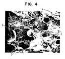
- the cured extrudatecomprises boron nitride flate at A; microspheres at B; and PTFE and silicone elastomer at C. [Note: In this particular SEM it is difficult to distinguish between the PTFE and the silicone elastomer.]
- the compositecomprises boron nitride flake at A; microspheres at B; PTFE fibrils caused by the expansion process at C; and a silicone elastomer D.
- the material of Figure 4has very novel properties as compared with the material of Figure 3 .
- First the material of Figure 4is 62 % less dense than the material of Figure 3 , yielding a very soft and compressible material as noted by the Shore A durometer and compressibility.
- the thermal conductivity of the material of Figure 4is greater than the extrudate sample. This is quite surprising since this sample has much less boron nitride per unit volume. This is in sharp contrast to conventional percolation theory.
- the resulting powderwas then lubricated at a level of 0.11 kg (0.25 lbs) lubricant per pound coagulum.
- the lubricant usedcomprised a mixture of 75% by weight silicone elastomer (Stygard® type 1-4105 obtained from Dow Corning, Inc.) and 25% by weight mineral spirits.
- the materialwas then re-frozen at -10°C for 4 hours, and re-screened through the same 6.35 mm (1/4") screen.
- the resulting powderwas left to dwell at room temperature 22°C ( ⁇ 72°F) for 24hours, then performed into 63.5 mm (150 mils) thick and 101.6 mm(4" wide).
- the tapewas then cariered to 2.61 mm (103 mils) and heated to 150°C for 5 minutes. This process yielded a porous PTFE composite with an interpenetrating cured silicone elastomer.
- the resulting compositehad the following properties:
Landscapes
- Chemical & Material Sciences (AREA)
- Engineering & Computer Science (AREA)
- Organic Chemistry (AREA)
- Materials Engineering (AREA)
- Health & Medical Sciences (AREA)
- Chemical Kinetics & Catalysis (AREA)
- Medicinal Chemistry (AREA)
- Polymers & Plastics (AREA)
- General Physics & Mathematics (AREA)
- Physics & Mathematics (AREA)
- Condensed Matter Physics & Semiconductors (AREA)
- Computer Hardware Design (AREA)
- Microelectronics & Electronic Packaging (AREA)
- Power Engineering (AREA)
- Manufacturing & Machinery (AREA)
- Compositions Of Macromolecular Compounds (AREA)
- Cooling Or The Like Of Semiconductors Or Solid State Devices (AREA)
- Manufacture Of Porous Articles, And Recovery And Treatment Of Waste Products (AREA)
- Laminated Bodies (AREA)
Description
- The present invention generally relates to an improved, thermally conductive polytetrafluoroethylene article.
- Integrated circuit ("IC") chips are steadily becoming smaller and more powerful. When compared to previous integrated circuit chips, this trend produces integrated chips which are significantly more dense and which perform many more functions in a given period of time. This results in an increase in the electrical current used by these integrated circuit chips. Consequently, smaller and more powerful integrated circuit chips tend to generate significantly more heat than larger and less powerful IC chips. Accordingly, heat management in electronic products has become a chief concern in IC chip design.
- Reliability of electronic circuits is dependent upon proper matches in the coefficients of expansion of various electronic components. As the temperature rises, mismatches in the coefficients of expansion cause stresses to develop between electronic components. Under these circumstances, any increase in operating temperature will have a negative effect on reliability. In an effort to control heat better, the use of various heat sinks is now a central focus in electronic equipment design. Examples of common heat sinks employed today include: IBM Thermal Conductive Modules (ITCM); Mitsubishi High Thermal Conduction Modules (HTCM); Hitachi SiC Heat Sinks; Fujitsu FACOM VP2000 Cooling Mechanisms; or metal plates of copper, aluminum, for example.
- In order to mate IC chips to heat sinks successfully, an interface which is elastic or otherwise conformable is preferred so as to ease installation and to minimize the effect of expansion and contraction between electronic components. Air gaps formed from improper installation of a chip to a heat sink, and/or expansion and contraction cycles during operation, can greatly impede the flow of heat from an IC chip. Conformability becomes especially important when the tolerances on the heat sink and chip tilt (in the case of flip chips) become large.
- Typically, thermal greases or thermally conductive thermosetting materials are used to take up tolerances between electronic components.See,e.g., United States Patent
5,028,984 . While such materials may operate with varying degrees of success in some applications, they are replete with shortcomings which detract from their usefulness. For example, these materials tend to be difficult to control and are prone to contaminating components of the electronic device. Care must be taken when using these materials to prevent unwanted contamination of solder joints and, in the case of electrically conductive thermoset resins, unwanted contamination of adjacent conductors. In practice, this usually results in a significant amount of wasted material. Additionally, clean up of such materials often requires the use of solvents. - In United States Patent
5,187,283 , a gasket-type material is disclosed comprising a thin-film surrounding a meltable metal core. In operation, the gasket is installed as an interface and its temperature is increased to melt the metal core and allow it to conform to the component parts. Unfortunately, this construction is believed to be ineffective in avoiding air gaps that can form during normal thermal cycling of the device. Further, as is a common problem with solid gasket materials in general, it is believed that this device may experience limited compressibility, requiring either application of excessive pressure to the mating surfaces, or use of unacceptably thick sections of the gasket. - In United States Patent
5,060,114 , conformability is sought by curing a metal or metal oxide filled silicone around the component to be cooled. Although this method may be successful, it is believed to be unduly complicated, costly, and time consuming for practical widespread use. - In addition to the foregoing, with most thermoset resins, greases, and gaskets employing a filler, there are additional constraints in successful heat dissipation. Most resins or greases tend to coat each individual particle of the thermal conductor within the resin, essentially insulating the conductor. This greatly reduces the overall effective thermal conductivity of the product in at least two ways. First, even a thinly coated surface (e.g., with a layer of silicone or epoxy) can serve as a thermal insulator, reducing the effective thermal conductivity of the product, particularly at contacting surfaces. Second, in order to overcome such thermal insulation, it is often necessary to apply substantial pressure to the interface in order to urge the thermally conductive particles into direct contact with one another to produce the necessary amount of conduction through the material. This often requires unacceptable compressive force for integrated circuits to produce a viable thermally conductive interface.
- As a result, most commercially available products can produce a conductivity in the range of only about 1.8 W/M °K (for greases) to 2.2 W/M °K (for epoxies). Even the most advanced (and expensive) materials, such as silver filled epoxies, only can achieve a conductivity in the range of 3-4 W/M °K. With regard to easily handled materials, such as self-adhesive materials, (available from Chomerics, Inc., Woburn, MA, under the trademark CHO-THERM Thermal Interface Materials, and from The Bergquist Company, Minneapolis, MN, under the trademark SIL-PAD Thermal Management Materials) these can typically achieve a conductivity of only about 0.37-0.95 W/M °K and 0.6-1.5 W/M °K, respectively. Although these commercial materials can produce better conductivities at high mounting pressures, they deliver extremely poor conductivity at very low mounting pressures (e.g., pressures below 13.8-20.6 kPa (2-3 lbs/in2)).
- Various other materials have been developed for use in electrical circuit boards, such as materials comprised of polytetrafluoroethylene (PTFE), and in many cases, porous PTFE as is taught in
U.S. Patent 3,543,566 .U.S. Patent 4,985,296 teaches the use of a PTFE material highly filled with inorganic filler that is between 0.1 and 5.0 mil thick and substantially pin hole free. This material is particularly suitable for use as an electrically or thermally conductive layer in printed circuit boards. However, the process of producing this material requires densification of the membrane, significantly reducing its conformability.U.S. Patent 4,996,097 teaches similar technology useful for a thin capacitive layer in a printed wiring board (PWB).U.S. Patent 4,518,737 teaches an extruded composite tape of ceramic filler and PTFE useful for its high dielectric constant. Such composites have not gained widespread acceptance because of the difficult processing techniques associated with their use. This can be very inconvenient, and often impossible to accomplish, especially for many adhesive applications where materials being bonded cannot withstand the necessary temperatures and pressures. - Japanese laid-open patent application
61-40328 62-100539 - In a similar fashion, British patent
2,195,269B EP-0248617B1 ), describes an article and process of imbibing expanded PTFE with a thermosetting resin which is useful as a substrate for a PWB. Unfortunately, previous attempts at this approach have been largely unsuccessful because high degrees of ceramic loading with the addition of ceramic filler tends to weaken the node and fibril structure. - Other problems experienced by many commercially available filled thermoset resins include: inadequate conformability (i.e., excessive compressive force required to get higher thermal conductivity); high flexural modulus after curing--resulting in substantial stress upon devices during thermal cycling; a lack of "compliance" - resulting in stress fractures if the resin is flexed longitudinally after curing; long curing times; and difficulty in manufacturing in high volumes.
- The foregoing illustrates limitations known to exist in present thermally conductive articles. Thus, it is apparent that it would be advantageous to provide an improved thermally conductive article directed to overcoming one or more of the limitations set forth above. It would be desirable is such an improved thermally conductive article is compressible, by as much as 2.54 mm (100 mils), under a low load, such as less than 344 kPa (50 pounds per square inch (PSI)). Accordingly, a suitable alternative is provided including features m ore fully disclosed hereinafter.
- According to a first aspect of the present invention there is provided a thermally conductive composite article having a polytetrafluoroethylene matrix, the thermally conductive composite article comprising:
- thermally conductive particles which are electrically non-conductive; and
- resilient hollow particles.
- The present invention relates to a thermally conductive composite article obtained from a predetermined precursor material. The thermally conductive composite article has a polytetrafluoroethylene matrix and comprises thermally conductive particles, and energy expandable hollow polymeric particles. In one embodiment of the present invention, the volume percent of the thermally conductive particles is at least 20 volume percent of the precursor material.
- The volume percent of the energy expanded hollow polymeric particles may be in a range from 1 to 15 volume percent of the precursor material. Preferred thermally conductive particles include the following thermally conductive particles, which are also electrically non-conductive, such as zinc oxide, aluminum oxide, boron nitride (BN), aluminum nitride (AIN), diamond powder, or silicon carbide (SiC).
- The thermally conductive composite article may include an elastomer material disposed within the composite article in a discontinuous fashion. Suitable elastomer materials include but are not limited to: silicone, polyurethane, ethylene/propylene, fluorosilicone, fluorocarbon elastomers, perfluoro elastomers, or other fluoroelastomer materials.
- It is, therefore, a purpose of the present invention to provide an improved, thermally conductive polytetrafluoroethylene article for use in a variety of applications.
- It is also a purpose of the present invention to provide an improved thermally conductive material for use as a thermally conductive gasket or interface.
- It is another purpose of the present invention to provide an improved, thermally conductive polytetrafluoroethylene material that is both soft and easily compressible, (e.g., a thermally conductive polytetrafluoroethylene material having a Shore A hardness of less than about 35 with the ability to compress at least 30 % at 688 kPa (100 PSI)) for use in a variety of applications requiring a flexible, conformable, and thermally conductive material throughout the structure of the article.
- The foregoing summary, as well as the following detailed description of a preferred embodiment of the present invention, will be better understood when read in conjunction with the appended drawings. For purposes of illustrating the invention, there is shown in the drawings an embodiment which is presently preferred. It should be understood, however, that the invention is not limited to the precise arrangement and instrumentality shown. In the drawings:
Figure 1 is a three-quarter isometric view of one embodiment of a thermally conductive article of the present invention shown mounted between component parts of an electronic device;Figure 2 is a cross-sectional view of another embodiment of a thermally conductive article of the present invention shown mounted between two component parts of an electronic device;Figure 3 is a scanning electron micrograph (SEM) of a cross-section of a cured extrudate (without expansion) in accordance with the teachings of the present invention, shown at 0.44 k magnification; andFigure 4 is an SEM of a cross-section of an expanded thermally conductive article in accordance with the teachings of the present invention, shown at 0.43k magnification.- Shown in
Figure 1 is a thermallyconductive interface 10 in accordance with the teachings of one embodiment of the present invention. The thermallyconductive interface 10 is mounted between two representative components, aheat sink 12 and aintegrated circuit 14, on anelectronic circuit board 16. Unlike many presently available thermally conductive interfaces, an interface made in accordance with the present invention provides exceptional conformability between component parts. As a result, with minimal compressive pressure, theinterface 10 forms a tight connection between theinterface 10 and abuttingsurfaces - As the term "tight" is used to describe the connection achieved between component parts using the interface of the present invention, it is meant to encompass a junction between component parts whereby the interface material has conformed to fill in irregularities in the surfaces of the component parts and significantly reduce or eliminate any air spaces therebetween. An interface made in accordance with the teachings of the present invention is particularly effective at establishing a tight connection at relatively low mounting pressures. As the term "low mounting pressures" is used in this application, it is intended to encompass the restricted pressures that sensitive electronic products (e.g., silica IC chips) can withstand, and includes pressure below about 206.8 kPa (30 lb/in2) (147 kg/m2).
- The
interface 10 of the present invention can be formed in a variety of shapes and sizes to fill particular needs. Shown inFigure 2 is another embodiment of a thermallyconductive interface 22 made in accordance with the teachings of the present invention. In this instance, theinterface 22 is deformed to provide a compliant connection between aheat sink 24 and anelectronic component 26. - In the present invention, a thermally conductive polytetrafluoroethylene (PTFE) artic!e is provided comprising energy expandable particulate blended with PTFE and thermally conductive particles. The PTFE article of the present invention is thermally conductive and easily compressed. Such a material may be effectively employed in a variety of useful applications, including but not limited to, the following: use as a thermal interface between an electronic device, or multiple devices, or a heat sink to aid in cooling of suitable device(s).
- The expandable particulate useful in the present invention exhibits intumescence upon application of heat. The expandable particulate is not homogeneous, i.e. it is not a polymeric bead, but rather comprises a polymeric shell having a central core comprised of a fluid material. A further characteristic is that the overall dimensions of the expandable particulate increase upon heating at a specific temperature.
- Expandable hollow polymeric particulate useful in a precursor composite material of the present invention includes those materials comprised of a polymeric shell and a core of at least one other material, either liquid or gaseous, most preferably a liquid at room temperature, in which the polymeric shell is essentially insoluble. A liquid core is advantageous because the degree of expansion is directly related to the volume change of the core material at the expansion temperature. For a gaseous core material, the volume expansion expected can be approximated from the general gas laws. However, expandable particulate comprising a liquid core material offers the opportunity to provide much larger volume changes, especially in those cases where a phase change takes place (i.e., the liquid volatilizes at or near the expansion temperature).
- Preferred expandable polymeric particulate (also called microspheres, microballoons, and microbubbles) useful in the precursor composite can have shells comprising copolymers such as vinyl chloride and vinylidene chloride, copolymers of vinyl chloride and acrylonitrile, copolymers of vinylidene chloride and acrylonitrile, copolymers of methacrylonitrile and acrylonitrile, and copolymers of styrene and acrylonitrile. Further can be mentioned are copolymers of methyl methacrylate containing up to about 2 percent by weight of styrene, copolymers of methyl methacrylate and up to about 50 percent by weight of ethyl methacrylate, and copolymers of methyl methacrylate and up to about 70 percent by weight of orthochlorostyrene. The unexpanded microspheres contain fluid, preferably volatile liquid, i.e., a blowing agent, which is conventional for microspheres of the type described here. Suitably, the blowing agent is 5 to 30 percent by weight of the microsphere. The microspheres can be added in different manners, as dried particles, wet cakes, or in a suspension, e.g. in an alcohol such as isopropanol.
- Unexpanded particulate desirably is in the size range of from about 0.1 micrometer to about 600 micrometers, preferably from 0.5 micrometer to 200 micrometers, and most preferably from 1 micrometer to 100 micrometers. Expanded particulate can have a size in the range of from about 0.12 micrometer to 1000 micrometers, preferably from 1 micrometer to 600 micrometers. After expansion, the volume of the expandable particulate increases by a factor of at least 1.5, preferably by a factor of at least 5, and most preferably by a factor of at least 10, and may even be as high as a factor of about 100.
- Suitable microspheres are commercially available from Nobel Industries of Sundsvall, Sweden, under the trademark EXPANCEL®. These microspheres may be obtained in a variety of sizes and forms, with expansion temperatures generally ranging from 80 to 130 °C. A typical EXPANCEL microsphere has an initial average diameter of 9 to 17 micrometers and an average expanded diameter of 40 to 60 micrometers. According to Nobel Industries, the microspheres have an unexpanded true density of 1250-1300 kg/m3, and an expanded density below 20 kg/m3.
- It should be understood that the use of the term "resilient" particulate or particles herein is intended to encompass any hollow resilient container, preferably polymerics, filled with volatile fluid which is adapted to expand. Although presently available microspheres are essentially ball-shaped particles adapted to expand when exposed to an energy source, it should be understood that such microspheres are quite resilient in their expanded form and can be compressed and released (e.g. through extrusion) to achieve the expansion required for the present invention. Additionally, it may be possible to form such products in a variety of other shapes, such as tubes, ellipsoids, cubes, particles. As such, the term "resilient" particulate or particles in the context of the present invention is intended to include all applicable forms and uses of these products now known or later developed and the particulate may be electrically non-conductive.
- A wide variety of blowing or raising agents may be enclosed within the polymeric shell of the expandable microspheres. They can be volatile having a number average molecular weight of at least 26, and a boiling point at atmospheric pressure about the same temperature range or below the range of the softening point of the resinous material of the polymeric shell when saturated with the particular blowing agent utilized.
- In one presently preferred embodiment of the present invention, EXPANCEL type 091 DU microspheres are employed. This product comprises an off-white dry powder with a particle size ranging between 10 and 40 micrometers. The shell of these microspheres comprise acrylonitrile. The volatile liquid comprises isopentane.
- It has been found that by mixing a dry preparation of EXPANCEL microspheres with a dispersion of PTFE, or similar polymer, and then heating the resulting composition, the polymer will undergo expansion in three-dimensions to achieve a fibrillated PTFE matrix.
- In accordance with the present invention, a precursor material comprised of: thermally conductive particulate; PTFE, in the form of paste, dispersion or powder; and microspheres, in the form of a dry powder or solution, is mixed in proportions of at least 20 to 90 volume percent conductive particulate, 1 to 15 volume percent EXPANCEL microspheres, and 5 to 70 volume percent PTFE, with proportions of 70 volume percent conductive particulate, 3 volume percent EXPANCEL microspheres and 27 volume percent PTFE being preferred in an embodiment comprising at least in part electrically conductive flakes. Mixture may occur by any suitable means, including dry blending of powders, wet blending, co-coagulation of aqueous dispersions and slurry filler, high shear mixing. As the term is used herein, "volume percent" shall mean a percentage of the volume of the precursor material.
- Thermally conductive particulate enmeshed within the resulting PTFE precursor material is the major component thereof. Preferred thermally conductive particles which are also electrically non-conductive, include zinc oxide, aluminum oxide, boron nitride (BN), aluminum nitride (AIN), diamond powder or silicon carbide (SiC). Additionally, a combination of two or more particulates can be used. Average size for conductive powders can be from 0.5µm to 400µm, preferably from 0.5µm to 100µ, and most preferably from 2 µm to 60 µm.
- The PTFE aqueous dispersion employed in producing the PTFE precursor of the present invention may be a milky-white aqueous suspension of PTFE particles. Typically, the PTFE aqueous dispersion will contain 20% to 70% by weight solids, the major portion of such solids being PTFE particles having a particle size in the range of from 0.05 micrometers to about 5.0 micrometers. Such PTFE aqueous dispersions are presently commercially available from the E. I. duPont de Nemours & Company, Inc., for example, under the tradename TEFLON® 3636, which is 18-24% by weight solids, being for the most part PTFE particles of 0.05 micrometers to 5.0 micrometers.
- A thickness of the above described precursor material may range from 3 mils to 150 mils, for example.
- Upon heating the precursor material, thickness increases due to the expansion of the energy expandable particulate. The amount of expansion observed is dependent on several factors, including the weight percent of energy expandable particulate present, the type of energy expandable particulate, the molecular weight of the polymeric shell of the energy expandable particulate, and the toughness of the PTFE matrix holding the precursor material together. An advantage of this process is the ability to produce thicknesses of greater than 6.35 mm (250 mils) after the expansion process.
- Temperatures needed for the thermal expansion step to occur are dependent on the type of polymer comprising the shell of the microsphere and on the particular blowing agent used. Typical temperatures range from 40°C to 220°C, preferably from 60°C to 200°C, most preferably from 80°C to 190°C.
- In addition to the composite article which has been described above, an alternate embodiment of the present invention may be made by adding an elastomer material, such as a silicone elastomer material (e.g. dimethyl siloxane) to the precursor material. In one embodiment of the present invention, this is achieved by compounding the filled fine powder coagulum with the dimethyl siloxane. A suitable dimethyl siloxane is Sylgard® type 1-4105, or Q1-4010, which may be obtained from Dow Corning. [It may also be suitable to use a silicone dioxide reinforced silicone material such as Q3-661 which may also be obtained from Dow Corning.] The siloxane is added on a weight per weight basis, and may be diluted with a solvent, such as mineral spirits, for example. In general, the siloxane may be added in amounts ranging from 1 to 50 percent, preferably from 5 to 20 percent, and most preferably from 10 to 15 percent. Other suitable elastomer materials include but are not limited to: silicone, polyurethane, ethylene/propylene, fluorosilicone, fluorocarbon elastomers, perfluoro elastomers, or other fluoroelastomer materials.
- Subsequently, this precursor material is heated in a range from 130°C to 190°C, to not only achieve expansion of the precursor material, but also to cross-link the siloxane and obtain a cured state of solid silicone elastomer. The resulting article is an easily compressible, thermally conductive PTFE composite, including a silicone elastomer disposed within the composite article in a discontinuous fashion.
- The addition of the elastomer material yields a composite with increased z-strength, tensile strength and elongation. It also provides some degree of resilience and increases the usable temperature range of the material. These desired properties are achieved without sacrificing softness/compressibility of the composite article.
- The following procedures were used to determine the properties of the materials created in the following examples.
- The expanded samples were measured for percent compression at 689.5 kPa (100 PSI) per ASTM F36-88.
- The density of the precursor material was obtained by using a 2.54 cm x 12.7 cm (1" x 6") template to cut a sample exactly 2.54 cm x 12.7 cm (1" x 6"). The sample was then weighed to the nearest .01 grams and the density calculated as follows:

where - M = Mass of sample to nearest .01 grams
- V = Volume (Length x width x thickness).
- Additionally, the expanded composite material was also measured in the manner described. The term % expansion will denote the % change in density of the sample in accordance with the following:

- Samples are cut to 5.71 cm square (2.25 inch squares). The test device consists of two copper blocks. The top block is heated and insulated. The bottom block is cooled by circulating water. The test device sits inside a frame that allows constant pressure to be applied to the test device. The test device was designed similarly to the device described in ASTM 5470 - 93, Standard Test Method for Thermal Transmission Properties of Thin Thermally Conductive Solid Electrical Insulation Materials.
- The hot block is heated with a given amount of power. The temperature drop down the hot block is monitored in two places with four thermocouples. The temperature at the hot surface is approximated by thermocouples that are mounted 0.79 mm (0.031 inches) away from the surface. The temperature at the test specimen surface is the average of the four thermocouple readings. The cold block is identical in design and thermocouple placement.
- Prior to mounting the specimen, the thickness is measured. The specimen is mounted on the bottom cold block. The top hot block is placed over the specimen. A given pressure is applied. The test consists of measuring the temperature drop across the test specimen as a function of the power supplied. Thermal resistance is calculated by dividing the temperature difference across the sample by the power supplied. The units are °C/W. Thermal conductivity is calculated by using Fourier's conduction equation:

where - k= thermal conductivity, W/m°C
- Q= power, W
- t= sample thickness, m
- A= sample area, m2
- ΔT= temperature drop across sample, °C
- The thermally conductive interface of the present invention is particularly designed for the dissipation of heat energy from component parts of electronic devices, such as power FET, computer logic circuits, and other high electronic density circuits. It should be understood, however, that applications of the present invention may include a wide selection of other uses, such as, but not limited to: power transformers, transistor packages (such as those designated TO-3, TO-5, TO-18, TO-36, TO-66, TO-220) and diode packages (such as those designated DO-4, DO-5).
- It should be likewise understood that without departing from the present invention the thermally conductive properties of the present invention may also be employed in the transference of heat to certain component parts, such as heat sinks, cold plates.
- Without intending to limit the scope of the present invention, the following examples illustrate how the present invention may be made and used.
- 145.6 g of boron nitride (type HCJ-48 from Advanced Ceramics, Inc.) and 5.2 g EXPENCEL type 091DU microspheres were slurried in a 1,643 g of di-ionized water. The slurry was then coagulated with 206.7 g of PTFE dispersion (type TE3636 obtained from E. I. dePont de Nemours & Company, Inc.). The coagulum was then dried at 90°C for 16 hours, frozen at -10°C for 24 hours and hand screened through a 6.35 mm (1/4") mesh metal screen. The resulting powder was lubricated at a level of 0.159 kg (0.35 lbs.) lubricant per pound of coagulum. The lubricant consisted of a mixture comprising 75% by weight silicone elastomer (Sylgard® type 1-4105 obtained from Dow Coming) and 25% by weight mineral spirits. The resulting material was allowed to dwell at room temperature (≈72°F) for 24 hours, then preformed into a 25.4 mm (1") diameter pellet and extruded into a tape approximately 44 mils thick and 50.8 mm (2") wide. The tape was then calandered to a thickness of 0.178 mm (7 mils.). A sample of this extrudate was then cured at 100°C for 5 minutes. See
Figure 3 for a cross-sectional photomicrograph. This step is necessary to cure the silicone and remove mineral spirits. However, 100°C is not hot enough to activate the EXPANCEL. This leaves a material in which we can measure the extrudate (or unexpanded) properties. The following data was then taken: - Thickness = 0.178 mm (7 mils)
- Density = 1.38 g/cc
- Percent Compression at 689.5 kPa (100 PSI) = 0
- Shore A Hardness = 60
- Thermal Conductivity at 6.89 kPa (10 PSI) - 0.83 w/m°C
- Thermal Conductivity at 689.5 kPa (100 PSI) - 1.53 w/m°C
- As best seen by reference to
Figure 3 , the cured extrudate comprises boron nitride flate at A; microspheres at B; and PTFE and silicone elastomer at C. [Note: In this particular SEM it is difficult to distinguish between the PTFE and the silicone elastomer.] - A separate piece of the extrudate material was then heated to 150°C for 5 minutes. (See
Figure 4 ). This type of heating causes the composite to expand (due to activation of the EXPANCEL) as the silicone elastomer cures and mineral spirits evaporate. The following data was then taken on this sample: - Thickness =0.432 mm (17 mils)
- Density = 0.53 g/cc ⇒ 62% expansion
- Percent of Compression at 689.5 kPa (100 PSI) = 31.3%
- Shore A Hardness = 18
- Thermal Conductivity at 68.9 kPa (10 PSI) = 0.63 w/m°C
- Thermal Conductivity at 689.5 kPa (100 PSI) = 2.04 w/m°C
- As best seen by reference to
Figure 4 , the composite comprises boron nitride flake at A; microspheres at B; PTFE fibrils caused by the expansion process at C; and a silicone elastomer D. - The material of
Figure 4 has very novel properties as compared with the material ofFigure 3 . First the material ofFigure 4 is 62 % less dense than the material ofFigure 3 , yielding a very soft and compressible material as noted by the Shore A durometer and compressibility. However, at 689.5 kPa (100 PSI) the thermal conductivity of the material ofFigure 4 is greater than the extrudate sample. This is quite surprising since this sample has much less boron nitride per unit volume. This is in sharp contrast to conventional percolation theory. - 2.26 kg (4.98 lbs) of Aluminum Nitride (type A500 FXWR obtained form ART, Inc.), and 87 g of EXPANCEL type 091DU microspheres was slurried in isopropyl alcohol and de-ionized water in a 37.8 litre (10 gallon) vessel. This slurry was then coagulated with 2.78 kg (6.12 lbs.) of PTFE dispersion (type TE3636 obtained from E.I. duPont de Nemours & Company, Inc.) at 22.5% solids. The resulting coagulum was dried at 95°C for 24 hours. The coagulum was then frozen at 10°C for 24 hours, and hand screened through a 6.35 mm (1/4 inch) mesh metal screen. The resulting powder was then lubricated at a level of 0.11 kg (0.25 lbs) lubricant per pound coagulum. The lubricant used comprised a mixture of 75% by weight silicone elastomer (Stygard® type 1-4105 obtained from Dow Corning, Inc.) and 25% by weight mineral spirits. The material was then re-frozen at -10°C for 4 hours, and re-screened through the same 6.35 mm (1/4") screen. The resulting powder was left to dwell at
room temperature 22°C (≈72°F) for 24hours, then performed into 63.5 mm (150 mils) thick and 101.6 mm(4" wide). The tape was then calandered to 2.61 mm (103 mils) and heated to 150°C for 5 minutes. This process yielded a porous PTFE composite with an interpenetrating cured silicone elastomer. The resulting composite had the following properties: - Thickness = 4.24 mm (167 mls)
- Density = 0.91 g/cc
- Percent Compression at 689.5 kPa (100 PSI) = 32.3%
- Shore A Hardness = 34
- Thermal Resistance at 689.5 kPa (100 PSI) = 0.775°C/w
- Thermal Conductivity at 689.5 kPa (100 PSI) = 2.1 w/m°C


Claims (11)
- A thermally conductive composite article having a polytetrafluoroethylene matrix, the thermally conductive composite article comprising:thermally conductive particles which are electrically non-conductive; andresilient hollow particles.
- An article as claimed in claim 1, wherein the thermally conductive particles are selected from boron nitride, aluminum nitride, diamond powder, silicon carbide, zinc oxide or aluminum oxide.
- An article as claimed in claim 1 or 2, further including an elastomer material.
- An article as claimed in claim 3, wherein the elastomer material is discontinuously disposed within the composite article.
- An article as claimed in claim 3 or 4, in which the elastomer is a silicone elastomer.
- An article as claimed in any preceding claim, wherein the resilient hollow particles are electrically non-conductive.
- An article as claimed in any preceding claim, said article having a density of less than 1.5 g/cc.
- An article as claimed in any preceding claim, having a Shore A hardness of less than 35.
- An article as claimed in claim 8, having a Shore A hardness of 20.
- An article as claimed in any preceding claim, in which the resilient hollow particles are polymeric.
- Use of a thermally conductive composite article according to claim 1 as a thermally conductive gasket or interface.
Priority Applications (1)
| Application Number | Priority Date | Filing Date | Title |
|---|---|---|---|
| EP06025013.1AEP1792938B8 (en) | 1996-06-27 | 1997-06-25 | Thermally conductive polytetrafluorethylene article |
Applications Claiming Priority (2)
| Application Number | Priority Date | Filing Date | Title |
|---|---|---|---|
| US08/671,560US5738936A (en) | 1996-06-27 | 1996-06-27 | Thermally conductive polytetrafluoroethylene article |
| US671560 | 1996-06-27 |
Related Child Applications (1)
| Application Number | Title | Priority Date | Filing Date |
|---|---|---|---|
| EP06025013.1ADivisionEP1792938B8 (en) | 1996-06-27 | 1997-06-25 | Thermally conductive polytetrafluorethylene article |
Publications (2)
| Publication Number | Publication Date |
|---|---|
| EP0816423A1 EP0816423A1 (en) | 1998-01-07 |
| EP0816423B1true EP0816423B1 (en) | 2008-11-05 |
Family
ID=24695001
Family Applications (2)
| Application Number | Title | Priority Date | Filing Date |
|---|---|---|---|
| EP97304490AExpired - LifetimeEP0816423B1 (en) | 1996-06-27 | 1997-06-25 | Thermally conductive polytetrafluoroethylene article |
| EP06025013.1AExpired - LifetimeEP1792938B8 (en) | 1996-06-27 | 1997-06-25 | Thermally conductive polytetrafluorethylene article |
Family Applications After (1)
| Application Number | Title | Priority Date | Filing Date |
|---|---|---|---|
| EP06025013.1AExpired - LifetimeEP1792938B8 (en) | 1996-06-27 | 1997-06-25 | Thermally conductive polytetrafluorethylene article |
Country Status (5)
| Country | Link |
|---|---|
| US (1) | US5738936A (en) |
| EP (2) | EP0816423B1 (en) |
| JP (2) | JPH1060206A (en) |
| KR (1) | KR100517421B1 (en) |
| DE (1) | DE69739082D1 (en) |
Families Citing this family (101)
| Publication number | Priority date | Publication date | Assignee | Title |
|---|---|---|---|---|
| US5904978A (en)* | 1995-12-15 | 1999-05-18 | W. L. Gore & Associates, Inc. | Electrically conductive polytetrafluoroethylene article |
| DE69709978T2 (en)* | 1996-04-30 | 2002-11-21 | Denki Kagaku Kogyo K.K., Tokio/Tokyo | Heat dissipating spacers for electronic devices |
| US5945217A (en)* | 1997-10-14 | 1999-08-31 | Gore Enterprise Holdings, Inc. | Thermally conductive polytrafluoroethylene article |
| US6498390B1 (en)* | 1998-09-16 | 2002-12-24 | Intel Corporation | Integrated circuit package that includes a thermally conductive tape which attaches a thermal element to a plastic housing |
| DE19924289A1 (en)* | 1999-05-27 | 2000-12-07 | Siemens Ag | Electronic circuit module with flexible intermediate layer between electronic components and heat-sink |
| US20030214800A1 (en)* | 1999-07-15 | 2003-11-20 | Dibene Joseph Ted | System and method for processor power delivery and thermal management |
| US6623279B2 (en) | 1999-07-15 | 2003-09-23 | Incep Technologies, Inc. | Separable power delivery connector |
| US6847529B2 (en)* | 1999-07-15 | 2005-01-25 | Incep Technologies, Inc. | Ultra-low impedance power interconnection system for electronic packages |
| US20030156400A1 (en)* | 1999-07-15 | 2003-08-21 | Dibene Joseph Ted | Method and apparatus for providing power to a microprocessor with intergrated thermal and EMI management |
| US6801431B2 (en)* | 1999-07-15 | 2004-10-05 | Incep Technologies, Inc. | Integrated power delivery and cooling system for high power microprocessors |
| US6947293B2 (en)* | 1999-07-15 | 2005-09-20 | Incep Technologies | Method and apparatus for providing power to a microprocessor with integrated thermal and EMI management |
| US6400565B1 (en) | 2000-04-21 | 2002-06-04 | Dell Products L.P. | Thermally conductive interface member |
| US6660241B2 (en)* | 2000-05-01 | 2003-12-09 | Saint-Gobain Ceramics & Plastics, Inc. | Highly delaminated hexagonal boron nitride powders, process for making, and uses thereof |
| US6794435B2 (en) | 2000-05-18 | 2004-09-21 | Saint Gobain Ceramics & Plastics, Inc. | Agglomerated hexagonal boron nitride powders, method of making, and uses thereof |
| US6557859B2 (en) | 2000-08-04 | 2003-05-06 | Cool Options, Inc. | Injection moldable elastomeric gasket |
| US6764975B1 (en) | 2000-11-28 | 2004-07-20 | Saint-Gobain Ceramics & Plastics, Inc. | Method for making high thermal diffusivity boron nitride powders |
| US7027304B2 (en)* | 2001-02-15 | 2006-04-11 | Integral Technologies, Inc. | Low cost thermal management device or heat sink manufactured from conductive loaded resin-based materials |
| US7167379B2 (en)* | 2001-02-16 | 2007-01-23 | Dibene Ii Joseph T | Micro-spring interconnect systems for low impedance high power applications |
| JP2004525242A (en)* | 2001-04-30 | 2004-08-19 | サンーゴバン セラミックス アンド プラスティクス,インコーポレイティド | Polymer processing aid and polymer processing method |
| US6547001B2 (en)* | 2001-06-08 | 2003-04-15 | Cool Shield, Inc. | Flexible glove-like heat sink |
| US6555486B2 (en)* | 2001-07-12 | 2003-04-29 | Cool Shield, Inc. | Thermally conductive silk-screenable interface material |
| US6645612B2 (en) | 2001-08-07 | 2003-11-11 | Saint-Gobain Ceramics & Plastics, Inc. | High solids hBN slurry, hBN paste, spherical hBN powder, and methods of making and using them |
| US6886625B1 (en) | 2001-08-23 | 2005-05-03 | Cool Options, Inc. | Elastomeric heat sink with a pressure sensitive adhesive backing |
| US6651732B2 (en)* | 2001-08-31 | 2003-11-25 | Cool Shield, Inc. | Thermally conductive elastomeric heat dissipation assembly with snap-in heat transfer conduit |
| US7013555B2 (en)* | 2001-08-31 | 2006-03-21 | Cool Shield, Inc. | Method of applying phase change thermal interface materials |
| US7311967B2 (en)* | 2001-10-18 | 2007-12-25 | Intel Corporation | Thermal interface material and electronic assembly having such a thermal interface material |
| US7083850B2 (en) | 2001-10-18 | 2006-08-01 | Honeywell International Inc. | Electrically conductive thermal interface |
| CN1319162C (en)* | 2001-10-18 | 2007-05-30 | 霍尼韦尔国际公司 | Heat transfer material and method of forming same |
| US6896045B2 (en)* | 2001-10-24 | 2005-05-24 | Cool Shield, Inc. | Structure and method of attaching a heat transfer part having a compressible interface |
| US20030128519A1 (en)* | 2002-01-08 | 2003-07-10 | International Business Machine Corporartion | Flexible, thermally conductive, electrically insulating gap filler, method to prepare same, and method using same |
| US6919115B2 (en)* | 2002-01-08 | 2005-07-19 | Cool Options, Inc. | Thermally conductive drive belt |
| JP4037658B2 (en)* | 2002-02-12 | 2008-01-23 | 独立行政法人海洋研究開発機構 | Crust core sample collection method, and antibacterial polymer gel and gel material used therefor |
| US6845013B2 (en)* | 2002-03-04 | 2005-01-18 | Incep Technologies, Inc. | Right-angle power interconnect electronic packaging assembly |
| US20030176516A1 (en)* | 2002-03-15 | 2003-09-18 | Greene, Tweed Of Delaware, Inc. | Cellular perfluoroelastomeric compositions, sealing members, methods of making the same and cellular materials for medical applications |
| JP2004051755A (en) | 2002-07-18 | 2004-02-19 | Ricoh Co Ltd | Elastic conductive resin and elastic conductive bonding structure |
| US6657297B1 (en)* | 2002-08-15 | 2003-12-02 | The Bergquist Company | Flexible surface layer film for delivery of highly filled or low cross-linked thermally conductive interface pads |
| US6851665B2 (en) | 2002-11-27 | 2005-02-08 | Paccar Inc | Air spring heat sink |
| US6919504B2 (en)* | 2002-12-19 | 2005-07-19 | 3M Innovative Properties Company | Flexible heat sink |
| US6776226B1 (en)* | 2003-03-12 | 2004-08-17 | National Starch And Chemical Investment Holding Corporation | Electronic device containing thermal interface material |
| US20040180209A1 (en)* | 2003-03-12 | 2004-09-16 | Chih-Min Cheng | Thermal interface material |
| US7229683B2 (en)* | 2003-05-30 | 2007-06-12 | 3M Innovative Properties Company | Thermal interface materials and method of making thermal interface materials |
| US7744991B2 (en)* | 2003-05-30 | 2010-06-29 | 3M Innovative Properties Company | Thermally conducting foam interface materials |
| US20050016714A1 (en)* | 2003-07-09 | 2005-01-27 | Chung Deborah D.L. | Thermal paste for improving thermal contacts |
| US6874573B2 (en)* | 2003-07-31 | 2005-04-05 | National Starch And Chemical Investment Holding Corporation | Thermal interface material |
| US7494635B2 (en) | 2003-08-21 | 2009-02-24 | Saint-Gobain Ceramics & Plastics, Inc. | Boron nitride agglomerated powder |
| JP2005158101A (en)* | 2003-11-21 | 2005-06-16 | Hitachi Ltd | Disk array device |
| US7344796B2 (en)* | 2004-02-18 | 2008-03-18 | Freudenberg-Nok General Partnership | Fluoroelastomer gasket compositions |
| US20050187331A1 (en)* | 2004-02-20 | 2005-08-25 | Yuan Hui L. | Fluoroelastomer gasket compositions |
| US20050187325A1 (en)* | 2004-02-20 | 2005-08-25 | Yuan Hui L. | Silicone gasket compositions |
| US20050270746A1 (en)* | 2004-06-04 | 2005-12-08 | Reis Bradley E | Insulating structure having combined insulating and heat spreading capabilities |
| CN100483024C (en)* | 2004-11-09 | 2009-04-29 | 李学霖 | Heat radiation structure of LED lamp |
| US7314898B2 (en)* | 2004-12-29 | 2008-01-01 | 3M Innovative Properties Company | Microsphere-filled polytetrafluoroethylene compositions |
| US7269015B2 (en)* | 2005-02-01 | 2007-09-11 | Tyco Electronics Corporation | Heat sink interface insert |
| TWI290012B (en)* | 2005-03-03 | 2007-11-11 | Mitac Technology Corp | Printed circuit board structure and manufacturing method thereof |
| US7598308B2 (en) | 2005-03-30 | 2009-10-06 | The Gates Corporation | Metal—elastomer compound |
| US20060228542A1 (en)* | 2005-04-08 | 2006-10-12 | Saint-Gobain Performance Plastics Corporation | Thermal interface material having spheroidal particulate filler |
| US7436669B2 (en)* | 2005-05-11 | 2008-10-14 | Sung-Po Huang | 3D multi-layer heat conduction diffusion plate |
| US20060266475A1 (en)* | 2005-05-24 | 2006-11-30 | American Standard Circuits, Inc. | Thermally conductive interface |
| US20060273450A1 (en)* | 2005-06-02 | 2006-12-07 | Intel Corporation | Solid-diffusion, die-to-heat spreader bonding methods, articles achieved thereby, and apparatus used therefor |
| JP2007005670A (en)* | 2005-06-27 | 2007-01-11 | Fujitsu Ltd | Electronic component package and joint assembly |
| US7527873B2 (en)* | 2006-02-08 | 2009-05-05 | American Standard Circuits | Thermally and electrically conductive interface |
| CN101803009B (en)* | 2007-09-11 | 2012-07-04 | 陶氏康宁公司 | Compositions, thermal interface materials including such compositions, methods of making and uses thereof |
| CN101803010B (en)* | 2007-09-11 | 2014-01-29 | 陶氏康宁公司 | Thermal interface material, electronic device containing the thermal interface material, and methods for their preparation and use |
| US8445102B2 (en)* | 2007-11-05 | 2013-05-21 | Laird Technologies, Inc. | Thermal interface material with thin transfer film or metallization |
| US9795059B2 (en) | 2007-11-05 | 2017-10-17 | Laird Technologies, Inc. | Thermal interface materials with thin film or metallization |
| US8545987B2 (en)* | 2007-11-05 | 2013-10-01 | Laird Technologies, Inc. | Thermal interface material with thin transfer film or metallization |
| US8076773B2 (en) | 2007-12-26 | 2011-12-13 | The Bergquist Company | Thermal interface with non-tacky surface |
| US20090208722A1 (en)* | 2008-02-18 | 2009-08-20 | John Francis Timmerman | Oriented Members for Thermally Conductive Interface Structures |
| JP4697243B2 (en)* | 2008-02-22 | 2011-06-08 | セイコーエプソン株式会社 | Bonded body and bonding method |
| JP4842294B2 (en) | 2008-04-30 | 2011-12-21 | 日東電工株式会社 | Porous sheet, method for producing the same, and heat insulating sheet |
| TWM351450U (en)* | 2008-07-24 | 2009-02-21 | Yi-Min Lin | Integrated circuit having porous ceramic heat dissipation plate |
| JP5322894B2 (en)* | 2008-11-12 | 2013-10-23 | 日東電工株式会社 | Insulating heat conductive sheet manufacturing method, insulating heat conductive sheet and heat radiation member |
| US8138239B2 (en)* | 2008-12-23 | 2012-03-20 | Intel Corporation | Polymer thermal interface materials |
| US7816785B2 (en)* | 2009-01-22 | 2010-10-19 | International Business Machines Corporation | Low compressive force, non-silicone, high thermal conducting formulation for thermal interface material and package |
| JP5491758B2 (en)* | 2009-03-31 | 2014-05-14 | 日本バルカー工業株式会社 | Filled fluororesin sheet, method for producing the same, and gasket |
| KR20110012780A (en)* | 2009-07-31 | 2011-02-09 | 엘지디스플레이 주식회사 | LCD Display |
| US20110140034A1 (en)* | 2009-08-26 | 2011-06-16 | Chiang-Chung Chang | Composite for heat-dissipating film |
| US20130120939A1 (en)* | 2010-05-21 | 2013-05-16 | Nokia Siemens Networks Oy | Method and device for thermally coupling a heat sink to a component |
| US20120155029A1 (en)* | 2010-12-20 | 2012-06-21 | Raytheon Company | Adaptive thermal gap pad |
| WO2012142613A1 (en)* | 2011-04-14 | 2012-10-18 | Ada Technologies, Inc. | Thermal interface materials and systems and devices containing the same |
| EP2551324B1 (en) | 2011-07-29 | 2014-01-01 | W.L.Gore & Associates Gmbh | Use of an anisotropic fluoropolymer for the conduction of heat |
| RU2467034C1 (en)* | 2011-08-24 | 2012-11-20 | Российская Федерация, от имени которой выступает Министерство образования и науки РФ (Минобрнауки РФ) | Accumulative antifriction and sealing material based on polytetrafluoroethylene |
| JP2015048414A (en)* | 2013-09-02 | 2015-03-16 | 日東電工株式会社 | Insulating heat conductive sheet |
| US10449781B2 (en) | 2013-10-09 | 2019-10-22 | Dover Europe Sarl | Apparatus and method for thermal transfer printing |
| US20150140881A1 (en)* | 2013-11-18 | 2015-05-21 | Xerox Corporation | Fuser member and composition of matter |
| TWI657132B (en)* | 2013-12-19 | 2019-04-21 | 德商漢高智慧財產控股公司 | Compositions having a matrix and encapsulated phase change materials dispersed therein, and electronic devices assembled therewith |
| WO2015120773A1 (en) | 2014-02-13 | 2015-08-20 | Honeywell International Inc. | Compressible thermal interface materials |
| CA2962391C (en) | 2014-09-26 | 2019-10-01 | W.L. Gore & Associates Gmbh | Process for the production of a thermally conductive article |
| CN105086301B (en)* | 2015-07-30 | 2017-11-28 | 洪小月 | A kind of high heat conduction PTFE tube for thermoelectricity heat exchanger |
| JP6842469B2 (en) | 2016-03-08 | 2021-03-17 | ハネウェル・インターナショナル・インコーポレーテッドHoneywell International Inc. | Phase change material |
| JP6523210B2 (en)* | 2016-05-19 | 2019-05-29 | 富士高分子工業株式会社 | Low temperature thermal conductive and high temperature insulating composition |
| WO2018062172A1 (en)* | 2016-09-30 | 2018-04-05 | 積水化学工業株式会社 | Thermally conductive, thermally expandable resin composition, thermally conductive, thermally expandable molded body, battery module, and battery pack |
| US11041103B2 (en) | 2017-09-08 | 2021-06-22 | Honeywell International Inc. | Silicone-free thermal gel |
| US10741471B2 (en) | 2018-01-19 | 2020-08-11 | Laird Technologies, Inc. | Highly compliant non-silicone putties and thermal interface materials including the same |
| DE102018101453A1 (en)* | 2018-01-23 | 2019-07-25 | Borgwarner Ludwigsburg Gmbh | Heating device and method for producing a heating rod |
| US11072706B2 (en) | 2018-02-15 | 2021-07-27 | Honeywell International Inc. | Gel-type thermal interface material |
| US11373921B2 (en) | 2019-04-23 | 2022-06-28 | Honeywell International Inc. | Gel-type thermal interface material with low pre-curing viscosity and elastic properties post-curing |
| CN114144877A (en) | 2019-07-23 | 2022-03-04 | 汉高知识产权控股有限责任公司 | Thermal management of high heat flux multi-element assemblies |
| US11040548B1 (en) | 2019-12-10 | 2021-06-22 | Dover Europe Sarl | Thermal transfer printers for deposition of thin ink layers including a carrier belt and rigid blade |
| EP3945624A1 (en)* | 2020-07-30 | 2022-02-02 | 3M Innovative Properties Company | Composite material comprising polytetrafluoroethylene and hexagonal boron nitride particles |
| CN113024975B (en)* | 2021-02-24 | 2022-11-08 | 浙江科赛新材料科技有限公司 | Large-diameter thin-wall polytetrafluoroethylene pasty extrusion pipe and preparation method thereof |
Family Cites Families (50)
| Publication number | Priority date | Publication date | Assignee | Title |
|---|---|---|---|---|
| CA962021A (en)* | 1970-05-21 | 1975-02-04 | Robert W. Gore | Porous products and process therefor |
| JPS5126940A (en)* | 1974-08-30 | 1976-03-05 | Japan Atomic Energy Res Inst | Hoshasenkokasei no nenchakuteepu mataha nenchakushiitoyojushisoseibutsu |
| US4008300A (en)* | 1974-10-15 | 1977-02-15 | A & P Products Incorporated | Multi-conductor element and method of making same |
| JPS6053408B2 (en)* | 1978-03-23 | 1985-11-26 | ニチコン株式会社 | Reduced semiconductor ceramic composition |
| JPS5825334B2 (en)* | 1978-05-31 | 1983-05-26 | 日東電工株式会社 | Manufacturing method of polytetrafluoroethylene porous material |
| US4518737A (en)* | 1978-12-26 | 1985-05-21 | Rogers Corporation | Dielectric material and method of making the dielectric material |
| US4265775A (en)* | 1979-08-16 | 1981-05-05 | International Business Machines Corporation | Non-bleeding thixotropic thermally conductive material |
| US4385093A (en)* | 1980-11-06 | 1983-05-24 | W. L. Gore & Associates, Inc. | Multi-component, highly porous, high strength PTFE article and method for manufacturing same |
| US4598011A (en)* | 1982-09-10 | 1986-07-01 | Bowman Jeffery B | High strength porous polytetrafluoroethylene product having a coarse microstructure |
| JPS59159225A (en)* | 1983-02-28 | 1984-09-08 | Teruaki Yogo | Bend driving device of bender |
| US4557957A (en)* | 1983-03-18 | 1985-12-10 | W. L. Gore & Associates, Inc. | Microporous metal-plated polytetrafluoroethylene articles and method of manufacture |
| US4606962A (en)* | 1983-06-13 | 1986-08-19 | Minnesota Mining And Manufacturing Company | Electrically and thermally conductive adhesive transfer tape |
| US4602678A (en)* | 1983-09-02 | 1986-07-29 | The Bergquist Company | Interfacing of heat sinks with electrical devices, and the like |
| US4574879A (en)* | 1984-02-29 | 1986-03-11 | The Bergquist Company | Mounting pad for solid-state devices |
| DE3412992A1 (en)* | 1984-04-06 | 1985-10-24 | Hoechst Ag, 6230 Frankfurt | BY RADIATION POLYMERIZABLE MIXTURE AND METHOD FOR APPLYING MARKINGS TO A SOLDER STOP PRESIS LAYER |
| US4853763A (en)* | 1984-06-27 | 1989-08-01 | The Bergquist Company | Mounting base pad means for semiconductor devices and method of preparing same |
| US4563488A (en)* | 1984-08-20 | 1986-01-07 | Japan Vilene Co. Ltd. | Insulator with high thermal conductivity |
| FR2576301B1 (en)* | 1985-01-24 | 1992-03-13 | Europ Propulsion | PROCESS FOR THE PREPARATION OF POROUS REFRACTORY MATERIALS, NOVEL PRODUCTS THUS OBTAINED AND THEIR APPLICATIONS IN THE PREPARATION OF ABRADABLE TURBINE RINGS |
| JPS62100539A (en) | 1985-10-25 | 1987-05-11 | Japan Gore Tex Inc | Filler-containing silicone rubber molding material and production thereof |
| US4810563A (en)* | 1986-03-14 | 1989-03-07 | The Bergquist Company | Thermally conductive, electrically insulative laminate |
| GB2195269B (en)* | 1986-06-02 | 1990-01-24 | Japan Gore Tex Inc | Process for making substrates for printed circuit boards |
| US5045249A (en)* | 1986-12-04 | 1991-09-03 | At&T Bell Laboratories | Electrical interconnection by a composite medium |
| US4945125A (en)* | 1987-01-05 | 1990-07-31 | Tetratec Corporation | Process of producing a fibrillated semi-interpenetrating polymer network of polytetrafluoroethylene and silicone elastomer and shaped products thereof |
| US4960612A (en)* | 1987-07-02 | 1990-10-02 | At&T Bell Laboratories | Thermal conductor assembly method |
| JPS6412406A (en)* | 1987-07-07 | 1989-01-17 | Nitto Denko Corp | Directional conductor and manufacture thereof |
| US4820376A (en)* | 1987-11-05 | 1989-04-11 | American Telephone And Telegraph Company At&T Bell Laboratories | Fabrication of CPI layers |
| CA1331245C (en)* | 1987-12-21 | 1994-08-02 | Carol Ann Latham | Thermally conductive ceramic/polymer composites |
| US5011872A (en)* | 1987-12-21 | 1991-04-30 | The Carborudum Company | Thermally conductive ceramic/polymer composites |
| JPH0623350B2 (en)* | 1988-01-20 | 1994-03-30 | 信越ポリマー株式会社 | Anisotropic conductive adhesive |
| GB2214719B (en)* | 1988-01-26 | 1991-07-24 | Gen Electric Co Plc | Housing for electronic device |
| CA1307355C (en)* | 1988-05-26 | 1992-09-08 | David C. Degree | Soft-faced semiconductor component backing |
| US5028984A (en)* | 1988-11-04 | 1991-07-02 | International Business Machines Corporation | Epoxy composition and use thereof |
| JPH0279453U (en)* | 1988-12-08 | 1990-06-19 | ||
| US4902857A (en)* | 1988-12-27 | 1990-02-20 | American Telephone And Telegraph Company, At&T Bell Laboratories | Polymer interconnect structure |
| JPH0291360U (en)* | 1988-12-29 | 1990-07-19 | ||
| US4985296A (en)* | 1989-03-16 | 1991-01-15 | W. L. Gore & Associates, Inc. | Polytetrafluoroethylene film |
| US4996097A (en)* | 1989-03-16 | 1991-02-26 | W. L. Gore & Associates, Inc. | High capacitance laminates |
| JPH03137138A (en)* | 1989-10-23 | 1991-06-11 | Matsushita Refrig Co Ltd | Foamed heat insulating material |
| US5060114A (en)* | 1990-06-06 | 1991-10-22 | Zenith Electronics Corporation | Conformable pad with thermally conductive additive for heat dissipation |
| GB9020428D0 (en)* | 1990-09-19 | 1990-10-31 | Gore W L & Ass Uk | Thermal control materials |
| US5137283A (en)* | 1991-06-27 | 1992-08-11 | Itt Corporation | Thermally conductive gasket device |
| US5213868A (en)* | 1991-08-13 | 1993-05-25 | Chomerics, Inc. | Thermally conductive interface materials and methods of using the same |
| US5397863A (en)* | 1991-09-13 | 1995-03-14 | International Business Machines Corporation | Fluorinated carbon polymer composites |
| JPH0584861A (en)* | 1991-09-30 | 1993-04-06 | Japan Gore Tex Inc | Composite material using silicone resin |
| US5328756A (en)* | 1992-01-31 | 1994-07-12 | Minnesota Mining And Manufacturing Company | Temperature sensitive circuit breaking element |
| US5209967A (en)* | 1992-01-31 | 1993-05-11 | Minnesota Mining And Manufacturing Company | Pressure sensitive membrane and method therefor |
| US5429869A (en)* | 1993-02-26 | 1995-07-04 | W. L. Gore & Associates, Inc. | Composition of expanded polytetrafluoroethylene and similar polymers and method for producing same |
| DE9303370U1 (en)* | 1993-03-08 | 1994-07-28 | W.L. Gore & Associates Gmbh, 85640 Putzbrunn | Round electrical cable |
| US5431571A (en)* | 1993-11-22 | 1995-07-11 | W. L. Gore & Associates, Inc. | Electrical conductive polymer matrix |
| US5904978A (en)* | 1995-12-15 | 1999-05-18 | W. L. Gore & Associates, Inc. | Electrically conductive polytetrafluoroethylene article |
- 1996
- 1996-06-27USUS08/671,560patent/US5738936A/ennot_activeExpired - Lifetime
- 1997
- 1997-06-25DEDE69739082Tpatent/DE69739082D1/ennot_activeExpired - Lifetime
- 1997-06-25EPEP97304490Apatent/EP0816423B1/ennot_activeExpired - Lifetime
- 1997-06-25EPEP06025013.1Apatent/EP1792938B8/ennot_activeExpired - Lifetime
- 1997-06-26JPJP9184626Apatent/JPH1060206A/ennot_activeWithdrawn
- 1997-06-27KRKR1019970027956Apatent/KR100517421B1/ennot_activeExpired - Lifetime
- 2007
- 2007-08-30JPJP2007223937Apatent/JP4129041B2/ennot_activeExpired - Lifetime
Also Published As
| Publication number | Publication date |
|---|---|
| DE69739082D1 (en) | 2008-12-18 |
| JP2008045132A (en) | 2008-02-28 |
| KR980002120A (en) | 1998-03-30 |
| KR100517421B1 (en) | 2006-03-14 |
| JP4129041B2 (en) | 2008-07-30 |
| JPH1060206A (en) | 1998-03-03 |
| US5738936A (en) | 1998-04-14 |
| EP0816423A1 (en) | 1998-01-07 |
| EP1792938A2 (en) | 2007-06-06 |
| EP1792938B1 (en) | 2014-08-13 |
| EP1792938B8 (en) | 2015-01-28 |
| EP1792938A3 (en) | 2010-09-29 |
Similar Documents
| Publication | Publication Date | Title |
|---|---|---|
| EP0816423B1 (en) | Thermally conductive polytetrafluoroethylene article | |
| US5545473A (en) | Thermally conductive interface | |
| US5945217A (en) | Thermally conductive polytrafluoroethylene article | |
| US5591034A (en) | Thermally conductive adhesive interface | |
| US6096414A (en) | High dielectric strength thermal interface material | |
| US7462309B2 (en) | Method for making thermoplastic thermally-conductive interface articles | |
| KR101672068B1 (en) | Thermally conductive foam product | |
| EP1376689B1 (en) | Radiating structural body of electronic part and radiating sheet used for the radiating structural body | |
| US6956739B2 (en) | High temperature stable thermal interface material | |
| US6822018B2 (en) | Thermally-conductive electrically-insulating polymer-base material | |
| US20160315030A1 (en) | Reusable thermoplastic thermal interface materials and methods for establishing thermal joints between heat sources and heat dissipating/removal structures | |
| KR100677818B1 (en) | Heat dissipation structure | |
| US20020012762A1 (en) | Double-side thermally conductive adhesive tape for plastic-packaged electronic components | |
| KR101489225B1 (en) | Potato shaped graphite filler, thermal interface materials and emi shielding | |
| US20030207064A1 (en) | Conformal thermal interface material for electronic components | |
| EP0696630A2 (en) | Heat conductive material and method for producing the same | |
| CA1331245C (en) | Thermally conductive ceramic/polymer composites | |
| US20040116571A1 (en) | Thermally conductive thermoplastic materials and method of making the same | |
| Sahu et al. | A review on thermal properties of epoxy composites as thermal interface material | |
| Wang et al. | Highly thermal conductive and electrically insulated graphene based thermal interface material with long-term reliability | |
| US20230032968A1 (en) | Graphite composite and electronic component | |
| US20070148425A1 (en) | Thermal interface material and semiconductor device incorporating the same | |
| JP2001523047A (en) | Non-conductive heat dissipator components | |
| Gowda et al. | Spherical boron nitride fillers for high performance thermal greases | |
| JP2001028414A (en) | Heat radiation spacer |
Legal Events
| Date | Code | Title | Description |
|---|---|---|---|
| PUAI | Public reference made under article 153(3) epc to a published international application that has entered the european phase | Free format text:ORIGINAL CODE: 0009012 | |
| AK | Designated contracting states | Kind code of ref document:A1 Designated state(s):AT BE CH DE DK ES FI FR GB GR IE IT LI LU MC NL PT SE | |
| 17P | Request for examination filed | Effective date:19980501 | |
| AKX | Designation fees paid | ||
| RBV | Designated contracting states (corrected) | ||
| REG | Reference to a national code | Ref country code:DE Ref legal event code:8566 | |
| 17Q | First examination report despatched | Effective date:20050608 | |
| 17Q | First examination report despatched | Effective date:20050608 | |
| GRAP | Despatch of communication of intention to grant a patent | Free format text:ORIGINAL CODE: EPIDOSNIGR1 | |
| RIC1 | Information provided on ipc code assigned before grant | Ipc:C08L 101/00 20060101ALI20071124BHEP Ipc:C08L 27/18 20060101ALI20071124BHEP Ipc:C08K 13/08 20060101AFI20071124BHEP | |
| GRAS | Grant fee paid | Free format text:ORIGINAL CODE: EPIDOSNIGR3 | |
| GRAA | (expected) grant | Free format text:ORIGINAL CODE: 0009210 | |
| RBV | Designated contracting states (corrected) | Designated state(s):DE ES FR GB IT NL SE | |
| AK | Designated contracting states | Kind code of ref document:B1 Designated state(s):DE ES FR GB IT NL SE | |
| REG | Reference to a national code | Ref country code:GB Ref legal event code:FG4D | |
| REF | Corresponds to: | Ref document number:69739082 Country of ref document:DE Date of ref document:20081218 Kind code of ref document:P | |
| NLV1 | Nl: lapsed or annulled due to failure to fulfill the requirements of art. 29p and 29m of the patents act | ||
| PG25 | Lapsed in a contracting state [announced via postgrant information from national office to epo] | Ref country code:ES Free format text:LAPSE BECAUSE OF FAILURE TO SUBMIT A TRANSLATION OF THE DESCRIPTION OR TO PAY THE FEE WITHIN THE PRESCRIBED TIME-LIMIT Effective date:20090216 | |
| PG25 | Lapsed in a contracting state [announced via postgrant information from national office to epo] | Ref country code:NL Free format text:LAPSE BECAUSE OF FAILURE TO SUBMIT A TRANSLATION OF THE DESCRIPTION OR TO PAY THE FEE WITHIN THE PRESCRIBED TIME-LIMIT Effective date:20081105 | |
| PG25 | Lapsed in a contracting state [announced via postgrant information from national office to epo] | Ref country code:SE Free format text:LAPSE BECAUSE OF FAILURE TO SUBMIT A TRANSLATION OF THE DESCRIPTION OR TO PAY THE FEE WITHIN THE PRESCRIBED TIME-LIMIT Effective date:20090205 | |
| PLBE | No opposition filed within time limit | Free format text:ORIGINAL CODE: 0009261 | |
| STAA | Information on the status of an ep patent application or granted ep patent | Free format text:STATUS: NO OPPOSITION FILED WITHIN TIME LIMIT | |
| 26N | No opposition filed | Effective date:20090806 | |
| PG25 | Lapsed in a contracting state [announced via postgrant information from national office to epo] | Ref country code:IT Free format text:LAPSE BECAUSE OF FAILURE TO SUBMIT A TRANSLATION OF THE DESCRIPTION OR TO PAY THE FEE WITHIN THE PRESCRIBED TIME-LIMIT Effective date:20081105 | |
| REG | Reference to a national code | Ref country code:FR Ref legal event code:PLFP Year of fee payment:20 | |
| PGFP | Annual fee paid to national office [announced via postgrant information from national office to epo] | Ref country code:GB Payment date:20160527 Year of fee payment:20 Ref country code:DE Payment date:20160524 Year of fee payment:20 | |
| PGFP | Annual fee paid to national office [announced via postgrant information from national office to epo] | Ref country code:FR Payment date:20160526 Year of fee payment:20 | |
| REG | Reference to a national code | Ref country code:DE Ref legal event code:R071 Ref document number:69739082 Country of ref document:DE | |
| REG | Reference to a national code | Ref country code:GB Ref legal event code:PE20 Expiry date:20170624 | |
| PG25 | Lapsed in a contracting state [announced via postgrant information from national office to epo] | Ref country code:GB Free format text:LAPSE BECAUSE OF EXPIRATION OF PROTECTION Effective date:20170624 |