EP0815874B1 - Instrument sterilization container having improved drainage and support for an instrument mat - Google Patents
Instrument sterilization container having improved drainage and support for an instrument matDownload PDFInfo
- Publication number
- EP0815874B1 EP0815874B1EP97304605AEP97304605AEP0815874B1EP 0815874 B1EP0815874 B1EP 0815874B1EP 97304605 AEP97304605 AEP 97304605AEP 97304605 AEP97304605 AEP 97304605AEP 0815874 B1EP0815874 B1EP 0815874B1
- Authority
- EP
- European Patent Office
- Prior art keywords
- drainage
- mat
- sterilization container
- container
- sterilization
- Prior art date
- Legal status (The legal status is an assumption and is not a legal conclusion. Google has not performed a legal analysis and makes no representation as to the accuracy of the status listed.)
- Expired - Lifetime
Links
- 230000001954sterilising effectEffects0.000titleclaimsdescription72
- 238000004659sterilization and disinfectionMethods0.000titleclaimsdescription57
- 238000000034methodMethods0.000claimsdescription14
- 239000007788liquidSubstances0.000claimsdescription11
- 239000012530fluidSubstances0.000claimsdescription2
- 229920002379silicone rubberPolymers0.000claimsdescription2
- 239000004945silicone rubberSubstances0.000claimsdescription2
- 239000000126substanceSubstances0.000description38
- 239000000463materialSubstances0.000description33
- MHAJPDPJQMAIIY-UHFFFAOYSA-NHydrogen peroxideChemical compoundOOMHAJPDPJQMAIIY-UHFFFAOYSA-N0.000description31
- 229920000106Liquid crystal polymerPolymers0.000description11
- 239000004977Liquid-crystal polymers (LCPs)Substances0.000description11
- 229920000728polyesterPolymers0.000description11
- -1polypropylenePolymers0.000description11
- 239000002243precursorSubstances0.000description10
- 230000007246mechanismEffects0.000description9
- 229920000139polyethylene terephthalatePolymers0.000description8
- 239000005020polyethylene terephthalateSubstances0.000description8
- 239000007789gasSubstances0.000description7
- 239000003365glass fiberSubstances0.000description7
- 229920000642polymerPolymers0.000description7
- VTYYLEPIZMXCLO-UHFFFAOYSA-LCalcium carbonateChemical compound[Ca+2].[O-]C([O-])=OVTYYLEPIZMXCLO-UHFFFAOYSA-L0.000description6
- 230000001590oxidative effectEffects0.000description6
- 239000000047productSubstances0.000description6
- IAYPIBMASNFSPL-UHFFFAOYSA-NEthylene oxideChemical compoundC1CO1IAYPIBMASNFSPL-UHFFFAOYSA-N0.000description5
- 239000004743PolypropyleneSubstances0.000description5
- 239000000203mixtureSubstances0.000description5
- 229920001155polypropylenePolymers0.000description5
- 230000002787reinforcementEffects0.000description5
- 239000012808vapor phaseSubstances0.000description5
- 239000004727NorylSubstances0.000description4
- 229920001207NorylPolymers0.000description4
- 229920004747ULTEM® 1000Polymers0.000description4
- 230000003993interactionEffects0.000description4
- 229920013683CelanesePolymers0.000description3
- 238000010521absorption reactionMethods0.000description3
- 229910000019calcium carbonateInorganic materials0.000description3
- 230000000694effectsEffects0.000description3
- 231100000225lethalityToxicity0.000description3
- 244000005700microbiomeSpecies0.000description3
- 239000002557mineral fiberSubstances0.000description3
- 238000000465mouldingMethods0.000description3
- 230000000930thermomechanical effectEffects0.000description3
- 239000004697PolyetherimideSubstances0.000description2
- 125000003118aryl groupChemical group0.000description2
- 238000004140cleaningMethods0.000description2
- 238000009833condensationMethods0.000description2
- 230000005494condensationEffects0.000description2
- 238000000354decomposition reactionMethods0.000description2
- 238000005202decontaminationMethods0.000description2
- 230000003588decontaminative effectEffects0.000description2
- 230000003247decreasing effectEffects0.000description2
- 238000013461designMethods0.000description2
- 230000005672electromagnetic fieldEffects0.000description2
- 230000002255enzymatic effectEffects0.000description2
- 239000000835fiberSubstances0.000description2
- 238000012986modificationMethods0.000description2
- 230000004048modificationEffects0.000description2
- 229920001707polybutylene terephthalatePolymers0.000description2
- 229920001601polyetherimidePolymers0.000description2
- 229920000098polyolefinPolymers0.000description2
- 229920001296polysiloxanePolymers0.000description2
- 230000008569processEffects0.000description2
- 230000001681protective effectEffects0.000description2
- 238000012414sterilization procedureMethods0.000description2
- 238000012546transferMethods0.000description2
- XLYOFNOQVPJJNP-UHFFFAOYSA-NwaterSubstancesOXLYOFNOQVPJJNP-UHFFFAOYSA-N0.000description2
- 239000004721Polyphenylene oxideSubstances0.000description1
- 239000004793PolystyreneSubstances0.000description1
- 229920012192Radel® R-5100Polymers0.000description1
- 229920004814ULTEM® CRS5011Polymers0.000description1
- 239000002253acidSubstances0.000description1
- 150000007513acidsChemical class0.000description1
- 239000000956alloySubstances0.000description1
- 229910045601alloyInorganic materials0.000description1
- QVGXLLKOCUKJST-UHFFFAOYSA-Natomic oxygenChemical compound[O]QVGXLLKOCUKJST-UHFFFAOYSA-N0.000description1
- 230000004888barrier functionEffects0.000description1
- 230000015572biosynthetic processEffects0.000description1
- 238000009395breedingMethods0.000description1
- 230000001488breeding effectEffects0.000description1
- HJJVPARKXDDIQD-UHFFFAOYSA-NbromuconazoleChemical compoundClC1=CC(Cl)=CC=C1C1(CN2N=CN=C2)OCC(Br)C1HJJVPARKXDDIQD-UHFFFAOYSA-N0.000description1
- 239000003599detergentSubstances0.000description1
- 238000009792diffusion processMethods0.000description1
- 229920001971elastomerPolymers0.000description1
- 238000005516engineering processMethods0.000description1
- 230000002708enhancing effectEffects0.000description1
- LYCAIKOWRPUZTN-UHFFFAOYSA-Nethylene glycolSubstancesOCCOLYCAIKOWRPUZTN-UHFFFAOYSA-N0.000description1
- 238000011156evaluationMethods0.000description1
- 239000000945fillerSubstances0.000description1
- 239000012467final productSubstances0.000description1
- 229920002313fluoropolymerPolymers0.000description1
- 239000004811fluoropolymerSubstances0.000description1
- 239000011521glassSubstances0.000description1
- 125000003827glycol groupChemical group0.000description1
- 230000005484gravityEffects0.000description1
- 238000007654immersionMethods0.000description1
- 238000011835investigationMethods0.000description1
- 239000011344liquid materialSubstances0.000description1
- 238000004519manufacturing processMethods0.000description1
- 238000005297material degradation processMethods0.000description1
- 239000005416organic matterSubstances0.000description1
- 239000001301oxygenSubstances0.000description1
- 229910052760oxygenInorganic materials0.000description1
- 239000012071phaseSubstances0.000description1
- 230000010399physical interactionEffects0.000description1
- 229920006380polyphenylene oxidePolymers0.000description1
- 229920002223polystyrenePolymers0.000description1
- 239000000843powderSubstances0.000description1
- 238000012545processingMethods0.000description1
- 230000000284resting effectEffects0.000description1
- 239000010935stainless steelSubstances0.000description1
- 229910001220stainless steelInorganic materials0.000description1
- 150000003457sulfonesChemical class0.000description1
- KKEYFWRCBNTPAC-UHFFFAOYSA-Lterephthalate(2-)Chemical compound[O-]C(=O)C1=CC=C(C([O-])=O)C=C1KKEYFWRCBNTPAC-UHFFFAOYSA-L0.000description1
Images


Classifications
- A—HUMAN NECESSITIES
- A61—MEDICAL OR VETERINARY SCIENCE; HYGIENE
- A61L—METHODS OR APPARATUS FOR STERILISING MATERIALS OR OBJECTS IN GENERAL; DISINFECTION, STERILISATION OR DEODORISATION OF AIR; CHEMICAL ASPECTS OF BANDAGES, DRESSINGS, ABSORBENT PADS OR SURGICAL ARTICLES; MATERIALS FOR BANDAGES, DRESSINGS, ABSORBENT PADS OR SURGICAL ARTICLES
- A61L2/00—Methods or apparatus for disinfecting or sterilising materials or objects other than foodstuffs or contact lenses; Accessories therefor
- A61L2/26—Accessories or devices or components used for biocidal treatment
- A—HUMAN NECESSITIES
- A61—MEDICAL OR VETERINARY SCIENCE; HYGIENE
- A61L—METHODS OR APPARATUS FOR STERILISING MATERIALS OR OBJECTS IN GENERAL; DISINFECTION, STERILISATION OR DEODORISATION OF AIR; CHEMICAL ASPECTS OF BANDAGES, DRESSINGS, ABSORBENT PADS OR SURGICAL ARTICLES; MATERIALS FOR BANDAGES, DRESSINGS, ABSORBENT PADS OR SURGICAL ARTICLES
- A61L2/00—Methods or apparatus for disinfecting or sterilising materials or objects other than foodstuffs or contact lenses; Accessories therefor
- A61L2/02—Methods or apparatus for disinfecting or sterilising materials or objects other than foodstuffs or contact lenses; Accessories therefor using physical phenomena
- A61L2/14—Plasma, i.e. ionised gases
- A—HUMAN NECESSITIES
- A61—MEDICAL OR VETERINARY SCIENCE; HYGIENE
- A61L—METHODS OR APPARATUS FOR STERILISING MATERIALS OR OBJECTS IN GENERAL; DISINFECTION, STERILISATION OR DEODORISATION OF AIR; CHEMICAL ASPECTS OF BANDAGES, DRESSINGS, ABSORBENT PADS OR SURGICAL ARTICLES; MATERIALS FOR BANDAGES, DRESSINGS, ABSORBENT PADS OR SURGICAL ARTICLES
- A61L2/00—Methods or apparatus for disinfecting or sterilising materials or objects other than foodstuffs or contact lenses; Accessories therefor
- A61L2/16—Methods or apparatus for disinfecting or sterilising materials or objects other than foodstuffs or contact lenses; Accessories therefor using chemical substances
- A61L2/22—Phase substances, e.g. smokes, aerosols or sprayed or atomised substances
- B—PERFORMING OPERATIONS; TRANSPORTING
- B65—CONVEYING; PACKING; STORING; HANDLING THIN OR FILAMENTARY MATERIAL
- B65D—CONTAINERS FOR STORAGE OR TRANSPORT OF ARTICLES OR MATERIALS, e.g. BAGS, BARRELS, BOTTLES, BOXES, CANS, CARTONS, CRATES, DRUMS, JARS, TANKS, HOPPERS, FORWARDING CONTAINERS; ACCESSORIES, CLOSURES, OR FITTINGS THEREFOR; PACKAGING ELEMENTS; PACKAGES
- B65D1/00—Rigid or semi-rigid containers having bodies formed in one piece, e.g. by casting metallic material, by moulding plastics, by blowing vitreous material, by throwing ceramic material, by moulding pulped fibrous material or by deep-drawing operations performed on sheet material
- B65D1/02—Bottles or similar containers with necks or like restricted apertures, designed for pouring contents
- B65D1/0223—Bottles or similar containers with necks or like restricted apertures, designed for pouring contents characterised by shape
Definitions
- This inventionrelates to a sterilization container for use in sterilizing, storing and transporting and presenting instruments, in particular medical instruments.
- reusable medical instrumentsrequire sterilization before each use.
- Many methodsare employed for sterilization, but the most prevalent methods include: steam autoclaving, vapor phase chemical sterilization and vapor phase chemical sterilization in combination with a plasma field.
- the chemical sterilantsinclude hydrogen peroxide and ethylene oxide.
- One of the most versatile, quickest and most effective methodsemploys an initial period of vapor phase hydrogen peroxide followed by application of an electromagnetic field which drives the hydrogen peroxide vapor into the plasma state of matter.
- the plasma phaseenhances the sterilization and when the electromagnetic field is released the plasma free radicals recombine to form water and oxygen.
- instrumentsare placed into a container and then the container is placed into the sterilization device.
- Portals for the passage of sterilizing mediamust be provided.
- the containeris usually provided with a filter material which allows passage of the sterilizing media through the portals and container yet prevents the ingress of microorganisms.
- the portal and filter materialmay be combined as in the Nichols U.S. Patent No.
- the containermay be provided with a plurality of apertures and then be wrapped prior to each sterilization in a filter wrapping material such as SPUNGUARD brand CSR wrap available from Kimberly Clark Corporation which is a spunbonded/meltblown/spunbonded (SMS) laminate consisting of nonwoven outer layers of spun-bonded polyolefins and an interior barrier layer of melt-blown polyolefins.
- a filter wrapping materialsuch as SPUNGUARD brand CSR wrap available from Kimberly Clark Corporation which is a spunbonded/meltblown/spunbonded (SMS) laminate consisting of nonwoven outer layers of spun-bonded polyolefins and an interior barrier layer of melt-blown polyolefins.
- SMSspunbonded/meltblown/spunbonded
- holding devices of one form or anotherhold one or more individual instruments within the container.
- the holding devicemay comprise clips or other such arrangements, which may or may not be specially adapted to hold a particular medical instrument.
- One popular holding devicesimply comprises a plurality of upwardly extending flexible projections, sometimes called fingers, which prevent the instruments from moving about within the container and provide minimal contact with the instruments. Typically, these are provided on a mat which lies in the bottom of the container.
- the ideal sterilization containerminimizes or eliminates areas in which liquids, particularly liquid water condensate from a steam autoclave, may collect, is compatible with all commonly employed sterilization procedures, has a long life, is easy to operate and can be provided for a reasonable cost.
- Containers presently knownsuffer from shortcomings which limit their performance in one or more of these areas. For instance, many trays designed for steam autoclaves are formed of stainless steel which may interfere with formation of a plasma in some systems. Other trays made of polymers may not have sufficient heat resistance to withstand repeated steam sterilization cycles. Some tray materials interact with chemical sterilants, and may even decompose the sterilant. Other materials may absorb excessive amounts of chemical sterilants, thereby decreasing the sterilization effectiveness by decreasing the amount of sterilant available for sterilizing.
- the present inventionovercomes these and other limitations in the prior art and provides compatibility with hydrogen peroxide vapor, liquid or gas plasma, steam autoclaves, ethylene oxide and other chemical or heat based sterilizing methods. It is durable, inexpensive to produce, enhances drainage and limits condensate entrapment.
- a sterilization container for sterilizing instrumentscomprises an enclosing wall; a base portion of said wall; a plurality of drainage apertures through the base portion; and a flexible elastomeric mat supported within the container, said mat having means for holding an instrument; characterised by: drainage wells associated with at least a portion of the drainage apertures; the drainage wells individually comprising: a supporting surface being formed by peaks above the drainage aperture, and an exit surface between the supporting surface and the drainage aperture wherein the exit surfaces of adjacent wells intersect to form the peaks, the exit surface being oriented downwardly toward the drainage aperture; wherein the flexible elastomeric mat is supported within the container upon the supporting surfaces.
- each drainage wellis associated with a single drainage aperture, and the exit surfaces surround the drainage aperture associated therewith. If the supporting surface comprises a sharp edge, it minimizes contact between the supporting surface and the mat while still providing adequate support for the mat. Preferably, the exit surface continuously slopes toward the drainage aperture associated therewith.
- the drainage wellsmay take the shape of inverted pyramids and be arranged in a uniform grid.
- the matis suitably formed of silicone rubber and the means for holding an instrument can comprise a plurality of upwardly extending flexible projections. However, any known holding means may be substituted therefor.
- the matpreferably has a plurality of mat apertures, at least a portion of which preferably align with corresponding drainage apertures.
- a method for sterilizing instruments using a sterilization container according to the present inventionis also provided.
- the flexible elastomeric matis placed within the sterilization container. Drainage wells are associated with at least a portion of the drainage apertures.
- the matis supported upon the supporting surfaces and the instrument is held in a position on the mat with a holding means.
- a sterilizing fluidis passed into the container and over the instrument and liquid is drained from within the container along the exit surfaces toward the drainage apertures and out through the drainage apertures associated therewith.
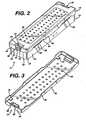
- FIG. 1illustrates a first embodiment of a sterilization container 10 according to the present invention.
- the container 10comprises a tray 12, a mat 14, and a lid 16.
- the tray 12comprises a rectangular base 18 from which extends upwardly an enclosing wall comprising two opposing side walls 20 and two opposing end walls 22. Corners 24 formed between the side walls 20 and end walls 22 are rounded for a pleasing appearance, improved strength, and to reduce sharp edges which may compromise the integrity of an operator's protective rubber glove (not shown).
- a fillet 26 between the base 18 and the side and end walls 20 and 22also enhances the strength of the tray 12.
- the base 18comprises a plurality of drainage wells 28, each one comprising a downwardly sloping exit surface 30 terminating in a drainage aperture 32.
- the sloping exit surfaces 30 of adjacent drainage wells 28intersect to form peaks 34.
- the peaks 34form distinct lines or singularities, as opposed to rounded interfaces between adjacent sloping exit surfaces 30. This minimizes the surface areas of the peaks 34 which form a supporting surface 71 to support the mat 14, thereby reducing the area of contact between the base 18 and mat 14. Thus, little space is provided in which condensate or other liquid matter may become trapped.
- the mat 14has a plurality of mat apertures 38 therethrough and a plurality of upwardly extending projections 36 for holding medical instruments (not shown) that are to be sterilized within the container 10. Apertures 38 on the mat 14 align with drainage apertures 32 through the tray base 18.
- the mat 14is formed of a silicone or other elastomeric substance which resists high heat associated with steam autoclaving, and also resists chemical attack from hydrogen peroxide, ethylene oxide, or other chemical sterilants or their precursors, particularly the oxidizing type sterilants. Further, the material of the mat 14 should not absorb or chemically interact with such chemical sterilants.
- the upwardly extending projections 36may take several forms. For instance, they may taper upwardly, or have constant diameter.
- the tipmay be flat, rounded or radiused. They may be relatively soft or they may be rigid.
- the total number and spacing of the projections 36may also be varied. Such mats are known in the art, and it is well within the ordinary skill of a practitioner in the art to vary these design parameters to achieve a desired overall effect.
- the container lid 16has a plurality of lid apertures 40 to promote the passage of sterilizing vapors therethrough.
- the lid apertures 40may align with the drainage apertures in the tray 12, but need not be so aligned.
- the lid 16further comprises downwardly depending sidewalls 42 and endwalls 44.
- the tray 12 and lid 16are sized so that the tray endwalls or sidewalls and endwalls 20 and 22 fit snugly within the lid sidewalls and endwalls 42 and 44.
- a latching mechanism 46is integrally formed in the tray 12 and lid 16.
- Each of the base endwalls 22has a recessed portion 48.
- a pair of U-shaped cutouts 50 in each recess portion 48define a flexible tang 52.
- An upper extent 54 of each tang 52comprises a sloped camming surface 56 and a retaining lip 58.
- Recessed portions 60 in the lid 16align with the endwall recesses 48 and comprise an aperture 62 and retaining lip 64.
- each tang 52is inserted into the corresponding aperture 62 in the lid 16 and cammed over the retaining lip 64 until the retaining lip 58 on the tang 52 snaps into engagement with the retaining lip 64.
- Inward pressure on the tang 52applied manually, disengages the retaining lips 58 and 64 to release the latch mechanism 46.
- each of the tray sidewalls 20 and lid sidewalls 42contain several shallow cutout portions 66. As best seen in FIG. 2, when the lid 16 and tray 12 are interconnected, the cutout portions 66 thereon align with each other to form shallow slit-like openings 68 into the container 10. This enhances the flow of sterilizing gases through the container 10.
- four pads 70are provided inside of the lid 16 to space the lid 16 from the tray 12 and thereby minimize any surface contact area therebetween which might block the flow of gas or liquid or which might trap, condensate, or other liquid material.
- FIG. 4illustrates the drainage enhancing features of the present invention.
- the peaks 34 of the base 18support the flexible mat 14. Condensate or other liquid which enters between the mat 14 and base 18 comes within one of the drainage wells 28.
- the small contact surface 71 formed between the peaks 34 and mat 14prevents condensate or other liquids from being trapped between surfaces of the base 18 and mat 14.
- the downwardly sloping exit surfaces 30 of the drainage wells 28encourage any condensate or other liquids to move toward the drainage apertures 32. Condensate then physically drains out of the container 10.
- the supporting characteristics of the peaks 34can not be over emphasized. Silicone and other elastomeric materials suitable for forming the mat 14 tend to soften considerably in high temperature sterilizing environments. Accordingly, it is crucial to properly support the mat 14.
- tray materialfor use in hydrogen peroxide or chemical based sterilization technology is influenced by the chemical resistance and inertness of the material with respect to the sterilant or precursor for chemical plasma.
- the inertness of the material with respect to the plasma precursoris even more critical due to possible low concentrations of precursor available to generate plasma in some preferred plasma methodologies.
- the tray materialshould be nonreactive to the sterilant(s), or the precursor(s) for the chemical plasma in order not to affect biological lethality of the sterilizer chamber.
- the materialshould also be resistant to the chemical and thermal environments during the cleaning and decontamination procedure of instruments and trays as commonly used in clinical situations. Hospitals typically use a washer/decontaminator operating at 182°C (270°F) as well as detergents and enzymatic cleaners for removing organic matter.
- the ideal tray materialshould further be compatible with all major sterilization methods employed by hospitals and the like, including steam (flash and gravity), ethylene oxide gas, and hydrogen peroxide based sterilizers.
- steamflash and gravity
- ethylene oxide gasethylene oxide gas
- hydrogen peroxide based sterilizersOne example of the hydrogen peroxide based plasma sterilization is the STERRAD Sterilization System that uses hydrogen peroxide plasma to eliminate microorganisms on medical instruments. Therefore, the ideal material should have adequate thermo-mechanical properties to withstand steam, exhibit low ethylene oxide residuals after processing, and have extremely low interaction with H 2 O 2 or other oxidative sterilants.
- tray materialsthere are preferred chemical structures, either with or without reinforcement, which can be considered as tray materials:
- the most preferred structuresare the wholly polyester aromatic liquid crystal polymers, which are polybenzoate-naphthalate and polybenzoate-terephthalate-bis phenol-isophthalate. Both neat and reinforced grades are preferred due to the structural strength of this material family.
- the most preferred reinforcements fillersare glass or mineral fibers, or fluoropolymers in powders,
- the first characteristic to be controlledis the surface smoothness of final product.
- the surface of the sterilization trayshould be as smooth as possible so as to reduce surface area/volume ratio. Since both chemical and physical interactions with sterilants or precursor(s) for chemical plasma and material degradation are a function of the surface area/volume ratio, smooth surfaces will reduce the rate of these interactions.
- the second characteristic to be controlledis wall thickness.
- Wall thicknessis integral to the structural strength of the tray or container.
- the condensation of chemical sterilant or precursor for chemical plasmashould be minimized.
- Condensationis a function of the thermal mass and heat transfer characteristics of the tray or container, which may reduce the amount of available sterilant or precursor for chemical plasma in vapor phase and thereby effect the biological lethality.
- the wall thickness of the tray or containershould be minimized.
- the preferred materials for forming the tray 12 and lid 16are as follows:
- FIGS. 5 and 6illustrate a second embodiment of a sterilization container according to the invention.
- the container 72comprises a tray 74, lid 76 and mat (not shown) similar to the previous embodiment. However, it incorporate an alternative latching mechanism 78.
- the lid 76comprises an apertured top wall 80; side and endwalls 82 and 84, respectively, depending therefrom.
- a latch member 86is integrally molded into a recessed portion 88 in each endwall 84 of the lid 76.
- a pair of torsion bars 90extend inwardly of the recess portion 88 from opposing sidewalls 92 thereof to rotatably support the latch member 86. The torsion bars 90 bias the latch member 86 into a standing, engaged position as shown best in FIG. 6, and allow a limited amount of rotation away from the engaged position.
- a notch 94 in each endwall 96 of the tray 74forms an engagement surface 98.
- the torsion bars 90return the latch member 86 to its standing, engaged position.
- All edges and surfaces of the latch member 86are rounded and smooth especially those on that portion 108 of the latch member facing outwardly of the recess 88. The only exception is the lip 100 which lies on that portion 109 of the latch member facing inwardly of the tray 74, to thereby present no sharp edges or surfaces which may engage and tear the users protective glove (not shown). All portions of the latching mechanism 78 are integrally molded with either the tray 74 or lid 76 thereby reducing manufacturing and assembly costs.
- the orientation of the latching mechanism 78may be reversed, such that the latch member 86 is formed in the tray 74.
- the lid 76could be adapted to pivot about a hinge (not shown) and of course, the latching mechanism 78 need not be provided in the endwall 84 but could be located elsewhere on the container 72. However, the orientation illustrated in FIG. 5 is particularly convenient.
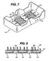
- FIGS. 7 and 8illustrate an alternative arrangement for a tray 110 according to the invention.
- the tray 110may be used with a sterilization container as in the first and second embodiment and differs primarily in its base 112.
- the base 112comprises a flat panel 114 having a plurality of apertures 116 therethrough. Additionally, a number of larger, elongated apertures 118 penetrate the panel 114 and an upwardly extending lip 120 encircles each of the elongated apertures 118.
- the lips 120support a mat 122 and further provide rigidity to the tray base 112. Apertures 123 through the mat 122 aligned with the elongated apertures 118 through the tray base 112 to provide an efficient diffusion path for sterilizing gases.
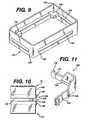
- FIG. 9illustrates a stacking device 124 for stacking sterilization trays 10 during a sterilization procedure.
- the stacking device 124is rectangular in shape and of slightly larger dimensions and than the sterilization tray 10 (not shown in FIG. 9). It comprises vertical sidewalls 126 and vertical endwalls 128.
- An L-shaped shelf member 130extends horizontally inwardly from each corner 132 of the stacking device 124.
- each of the sidewalls 126 and endwalls 128has elongated openings 134 therethrough of similar vertical dimensions to the shelf member 130 so that when containers 10 are stacked using the stacking device 124, the flow of sterilizing gases into and out of the individual containers 10 is not impeded by the stacking device 124.
- FIG. 10shows two sterilization containers 10, each wrapped in a sterile wrap material 136.
- the stacking member 124sits atop a first tray 10 with the shelf member 130 resting upon the tray 10.
- the second tray 10rests upon the shelf member 130.
- Both trays 10are positioned within the side and endwalls 126 and 128 of the stacking device. Thus, the two trays 10 are stacked and separated from each other with a full and open flow path thereabout.
- FIG. 11illustrates an alternative embodiment of a stacking device 138.
- each of the side and endwalls 140 and 142respectively have a low vertical profile vertically offset from a shelf member 144 to thereby provide an open flow path to the stacked trays (not shown in FIG. 11).
- Vertical ribs 146 on the side and endwalls 140 and 142provide rigidity and maintain an open flow path, if the stacking device is placed next to another stacking device or flat surface.
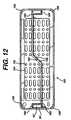
- FIG. 12illustrates an alternative embodiment of a lid 150 according to the invention.
- the lid 150duplicates the lid 16 of FIGS. 1 and 3, with several modifications. Accordingly, features similar to those on the lid 16 will be designated with similar numerals with the addition of a single prime symbol ('). Specifically, the lid 150 differs from the lid 16 in its mixture of round and elongated apertures 152 and 154 respectively. Also, an additional fillet 156 has been added at each corner which both strengthens the lid 150 aids in lifting the lid 150 above the base 8 (not shown in FIG. 12) for improved circulation.
- Liquid crystal polymersare known for their difficulty in molding.
- One particular problemarises where opposing flows of molten polymer meet. Such areas often have reduced strength and accordingly it is desirable to locate them away from areas of the molded article which will be subjected to high levels of stress.
- the recess 60'is formed by a core pin in the mold (not shown). The molten polymer flows around the core pin and meets to enclose the recess 60'. Normally these flows would meet at the retaining lip 64'. However, this area is subjected to high stresses.
- the lid 150is formed with a pair of flow leaders 158, each leading from a center area 160 of the lid 150 where the molten polymer is injected in the molding process and leading to an inside corner 162 of the respective recesses 60'. During the molding process the molten polymer thus flows around the core pin and the opposing flows meet at a side portion 164 of the recess 60'.
Landscapes
- Health & Medical Sciences (AREA)
- Public Health (AREA)
- General Health & Medical Sciences (AREA)
- Epidemiology (AREA)
- Life Sciences & Earth Sciences (AREA)
- Animal Behavior & Ethology (AREA)
- Veterinary Medicine (AREA)
- Engineering & Computer Science (AREA)
- Chemical & Material Sciences (AREA)
- Plasma & Fusion (AREA)
- Physics & Mathematics (AREA)
- Chemical Kinetics & Catalysis (AREA)
- General Chemical & Material Sciences (AREA)
- Ceramic Engineering (AREA)
- Mechanical Engineering (AREA)
- Apparatus For Disinfection Or Sterilisation (AREA)
- External Artificial Organs (AREA)
Description
- This invention relates to a sterilization container for use in sterilizing,storing and transporting and presenting instruments, in particular medicalinstruments.
- Most, reusable medical instruments require sterilization before each use.Many methods are employed for sterilization, but the most prevalent methodsinclude: steam autoclaving, vapor phase chemical sterilization and vapor phasechemical sterilization in combination with a plasma field. The chemical sterilantsinclude hydrogen peroxide and ethylene oxide. One of the most versatile, quickestand most effective methods employs an initial period of vapor phase hydrogenperoxide followed by application of an electromagnetic field which drives thehydrogen peroxide vapor into the plasma state of matter. The plasma phaseenhances the sterilization and when the electromagnetic field is released the plasmafree radicals recombine to form water and oxygen.
- Typically, instruments are placed into a container and then the container isplaced into the sterilization device. Portals for the passage of sterilizing mediamust be provided. Also, the container is usually provided with a filter materialwhich allows passage of the sterilizing media through the portals and container yetprevents the ingress of microorganisms. The portal and filter material may becombined as in the Nichols U.S. Patent No. 4,704,254, issued November 3, 1987and incorporated herein by reference, or the container may be provided with aplurality of apertures and then be wrapped prior to each sterilization in a filterwrapping material such as SPUNGUARD brand CSR wrap available fromKimberly Clark Corporation which is a spunbonded/meltblown/spunbonded (SMS) laminate consisting of nonwoven outer layers of spun-bonded polyolefins and aninterior barrier layer of melt-blown polyolefins.
- Usually, holding devices of one form or another hold one or moreindividual instruments within the container. The holding device may compriseclips or other such arrangements, which may or may not be specially adapted tohold a particular medical instrument. One popular holding device simplycomprises a plurality of upwardly extending flexible projections, sometimes calledfingers, which prevent the instruments from moving about within the container andprovide minimal contact with the instruments. Typically, these are provided on amat which lies in the bottom of the container.
- The ideal sterilization container minimizes or eliminates areas in whichliquids, particularly liquid water condensate from a steam autoclave, may collect,is compatible with all commonly employed sterilization procedures, has a longlife, is easy to operate and can be provided for a reasonable cost. Containerspresently known suffer from shortcomings which limit their performance in one ormore of these areas. For instance, many trays designed for steam autoclaves areformed of stainless steel which may interfere with formation of a plasma in somesystems. Other trays made of polymers may not have sufficient heat resistance towithstand repeated steam sterilization cycles. Some tray materials interact withchemical sterilants, and may even decompose the sterilant. Other materials mayabsorb excessive amounts of chemical sterilants, thereby decreasing thesterilization effectiveness by decreasing the amount of sterilant available forsterilizing.
- When using mats with flexible fingers, condensate and other liquids maybecome trapped between the mat and the bottom of the tray, providing a potentialbreeding ground for microorganisms. Brooks, Jr., in U.S. Patent No. 5,098,676,addresses this problem by providing a plurality of small feet on the bottom of themat to elevate it off of the tray bottom. Allen et al., in U.S. Patent No.5,407,648, address the problem by providing ribs on the tray bottom upon which the mat rests. Both references teach a flat tray bottom which does not promote gooddrainage.
- The present invention overcomes these and other limitations in the prior art andprovides compatibility with hydrogen peroxide vapor, liquid or gas plasma, steamautoclaves, ethylene oxide and other chemical or heat based sterilizing methods. It isdurable, inexpensive to produce, enhances drainage and limits condensate entrapment.
- A sterilization container for sterilizing instruments according to the presentinvention comprises an enclosing wall; a base portion of said wall; a plurality of drainageapertures through the base portion; and a flexible elastomeric mat supported within thecontainer, said mat having means for holding an instrument; characterised by: drainagewells associated with at least a portion of the drainage apertures; the drainage wellsindividually comprising: a supporting surface being formed by peaks above the drainage aperture, and an exitsurface between the supporting surface and the drainage aperture wherein the exit surfaces of adjacent wells intersect toform the peaks, the exit surface beingoriented downwardly toward the drainage aperture; wherein the flexible elastomeric mat issupported within the container upon the supporting surfaces.
- Preferably, each drainage well is associated with a single drainage aperture, and theexit surfaces surround the drainage aperture associated therewith. If the supporting surfacecomprises a sharp edge, it minimizes contact between the supporting surface and the matwhile still providing adequate support for the mat. Preferably, the exit surface continuouslyslopes toward the drainage aperture associated therewith. The drainage wells may take theshape of inverted pyramids and be arranged in a uniform grid. The mat is suitably formedof silicone rubber and the means for holding an instrument can comprise a plurality ofupwardly extending flexible projections. However, any known holding means may be substituted therefor. The mat preferably has a plurality of mat apertures, at least aportion of which preferably align with corresponding drainage apertures.
- A method for sterilizing instruments using a sterilization container according to the present invention isalso provided. The flexible elastomeric mat is placed within the sterilizationcontainer.Drainage wells areassociated with at least a portion of the drainage apertures.The mat is supported upon the supporting surfaces and the instrument is held in aposition on the mat with a holding means. A sterilizing fluid is passed into thecontainer and over the instrument and liquid is drained from within the containeralong the exit surfaces toward the drainage apertures and out through the drainage apertures associated therewith.
- FIG. 1 is an exploded, perspective view of a sterilization containeraccording to the invention;
- FIG. 2 is a perspective view of the assembled sterilization container ofFIG. 1;
- FIG. 3 is a perspective view of the inverted lid of the sterilization containerof FIG. 1;
- FIG. 4 is a cross-section taken along lines 4 -- 4 of FIG. 2;
- FIG. 5 is a perspective, disassembly view of a portion of a sterilizationcontainer according to the present invention which illustrates an alternativelatching mechanism according to the present invention;
- FIG. 6 is a cross-section of the latching mechanism of FIG. 5, with thelatch shown in the closed position;
- FIG. 7 is a perspective view of a further embodiment of a sterilization trayaccording to the present invention;
- FIG. 8 is a cross-section taken along line 8 - 8 of FIG. 7;
- FIG. 9 is a perspective view of a stacking device according to the presentinvention;
- FIG. 10 is a side view of the stacking device of FIG. 9 positioned betweentwo sterilization containers to stack and separate the containers;
- FIG. 11 is a perspective view of a further embodiment of a stacking deviceaccording to the present invention; and
- FIG. 12 is underside plan view of a further embodiment of a lid accordingto the present invention.
- FIG. 1 illustrates a first embodiment of a
sterilization container 10according to the present invention. Thecontainer 10 comprises atray 12, amat 14, and alid 16. Thetray 12 comprises arectangular base 18 from which extendsupwardly an enclosing wall comprising twoopposing side walls 20 and twoopposing end walls 22.Corners 24formed between theside walls 20 andend walls 22 are rounded for a pleasingappearance, improved strength, and to reduce sharp edges which may compromisethe integrity of an operator's protective rubber glove (not shown). Afillet 26between thebase 18 and the side andend walls tray 12. - The
base 18 comprises a plurality ofdrainage wells 28, each onecomprising a downwardly slopingexit surface 30 terminating in adrainage aperture 32. The slopingexit surfaces 30 ofadjacent drainage wells 28 intersect to formpeaks 34. Preferably, thepeaks 34 form distinct lines or singularities, as opposed torounded interfaces between adjacentsloping exit surfaces 30. This minimizes thesurface areas of thepeaks 34 which form a supportingsurface 71 to support themat 14, thereby reducing the areaof contact between thebase 18 andmat 14. Thus, little space is provided inwhich condensate or other liquid matter may become trapped. - The
mat 14 has a plurality ofmat apertures 38 therethrough and a pluralityof upwardly extendingprojections 36 for holding medical instruments (not shown)that are to be sterilized within thecontainer 10.Apertures 38 on themat 14 alignwithdrainage apertures 32 through thetray base 18. Preferably, themat 14 isformed of a silicone or other elastomeric substance which resists high heatassociated with steam autoclaving, and also resists chemical attack from hydrogenperoxide, ethylene oxide, or other chemical sterilants or their precursors,particularly the oxidizing type sterilants. Further, the material of themat 14should not absorb or chemically interact with such chemical sterilants. - The upwardly extending
projections 36 may take several forms. Forinstance, they may taper upwardly, or have constant diameter. The tip may beflat, rounded or radiused. They may be relatively soft or they may be rigid. Thetotal number and spacing of theprojections 36 may also be varied. Such mats areknown in the art, and it is well within the ordinary skill of a practitioner in the artto vary these design parameters to achieve a desired overall effect. - The
container lid 16 has a plurality oflid apertures 40 to promote thepassage of sterilizing vapors therethrough. The lid apertures 40 may align withthe drainage apertures in thetray 12, but need not be so aligned. Thelid 16further comprises downwardly depending sidewalls 42 andendwalls 44. - Turning also now to FIG. 2, the
tray 12 andlid 16 are sized so that thetray endwalls or sidewalls and endwalls 20 and 22 fit snugly within the lidsidewalls and endwalls 42 and 44. Preferably, alatching mechanism 46 isintegrally formed in thetray 12 andlid 16. Each of the base endwalls 22 has arecessedportion 48. A pair ofU-shaped cutouts 50 in eachrecess portion 48define aflexible tang 52. Anupper extent 54 of eachtang 52 comprises a slopedcamming surface 56 and a retaininglip 58. Recessedportions 60 in thelid 16align with the endwall recesses 48 and comprise anaperture 62 and retaininglip 64. To engage thelatch mechanism 46, thecamming surface 56 on eachtang 52is inserted into the correspondingaperture 62 in thelid 16 and cammed over theretaininglip 64 until the retaininglip 58 on thetang 52 snaps into engagementwith the retaininglip 64. Inward pressure on thetang 52, applied manually,disengages the retaininglips latch mechanism 46. - To enhance the flow of sterilizing gases through the
container 10, each ofthe tray sidewalls 20 and lid sidewalls 42 contain severalshallow cutout portions 66. As best seen in FIG. 2, when thelid 16 andtray 12 are interconnected, thecutout portions 66 thereon align with each other to form shallow slit-like openings 68 into thecontainer 10. This enhances the flow of sterilizing gases through thecontainer 10. - Turning to FIG. 3, four
pads 70 are provided inside of thelid 16 to spacethelid 16 from thetray 12 and thereby minimize any surface contact areatherebetween which might block the flow of gas or liquid or which might trap,condensate, or other liquid material. - FIG. 4 illustrates the drainage enhancing features of the present invention.The
peaks 34 of the base 18 support theflexible mat 14. Condensate or otherliquid which enters between themat 14 andbase 18 comes within one of thedrainage wells 28. Thesmall contact surface 71 formed between thepeaks 34 andmat 14 prevents condensate or other liquids from being trapped between surfaces of thebase 18 andmat 14. The downwardly sloping exit surfaces 30 of thedrainagewells 28 encourage any condensate or other liquids to move toward thedrainageapertures 32. Condensate then physically drains out of thecontainer 10. Thesupporting characteristics of thepeaks 34 can not be over emphasized. Siliconeand other elastomeric materials suitable for forming themat 14 tend to softenconsiderably in high temperature sterilizing environments. Accordingly, it iscrucial to properly support themat 14. - The selection of tray material for use in hydrogen peroxide or chemicalbased sterilization technology is influenced by the chemical resistance andinertness of the material with respect to the sterilant or precursor for chemicalplasma. For chemical plasma sterilization methods which depend on excited freeradicals, the inertness of the material with respect to the plasma precursor is evenmore critical due to possible low concentrations of precursor available to generateplasma in some preferred plasma methodologies. The tray material should be nonreactiveto the sterilant(s), or the precursor(s) for the chemical plasma in order notto affect biological lethality of the sterilizer chamber. For ease of operation, thematerial should also be resistant to the chemical and thermal environments duringthe cleaning and decontamination procedure of instruments and trays as commonlyused in clinical situations. Hospitals typically use a washer/decontaminatoroperating at 182°C (270°F) as well as detergents and enzymatic cleaners for removingorganic matter.
- The ideal tray material should further be compatible with all majorsterilization methods employed by hospitals and the like, including steam (flashand gravity), ethylene oxide gas, and hydrogen peroxide based sterilizers. Oneexample of the hydrogen peroxide based plasma sterilization is the STERRADSterilization System that uses hydrogen peroxide plasma to eliminatemicroorganisms on medical instruments. Therefore, the ideal material should haveadequate thermo-mechanical properties to withstand steam, exhibit low ethylene oxide residuals after processing, and have extremely low interaction with H2O2 orother oxidative sterilants.
- We have rigorously examined and tested many materials to identify amaterial suitable for such varied and extreme service environments. As a result ofour investigations, we have found the preferred materials to be neat (non-reinforced)and reinforced polyester based liquid crystal polymers, neat andreinforced polyesters, and reinforced polypropylene. The most preferred materialis neat or reinforced polyester liquid crystal polymer, or its blend with the abovementioned polymers. One commercially available example of a suitable liquidcrystal polymer is the Vectra® family produced by the Hoechst CelaneseCorporation.
- Within each family group, there are preferred chemical structures, eitherwith or without reinforcement, which can be considered as tray materials:
- I. Reinforced polypropylene, especially when reinforced with calciumcarbonate or glass fiber, provides the chemical inertness andstructural properties required for multi-sterilization application.
- II. Polyester type polymers have a variety of basic structures, amongthem:
- 1. Polyethylene terephthalate (PET) with the following chemicalstructure:

- 2. Polybutylene terephthalate (PBT), in which chemicalstructure is:and

- 3. Polycyclohexylene terephthalate (PCT), with the followingchemical structure:
 PCT is available from Eastman Chemical Company under the tradename of"Ektar", in a variety of unmodified and modified structures. Modification mayinclude acids and glycol structures. Among the polyester family, the structure of polyethylene terephthalate ispreferred. The most preferred configuration is glass fiber reinforced PET. Thefiber reinforcement provides structural strength for steam autoclave operation andis preferred in oxidative chemical vapor or oxidative chemical plasma sterilizationmethods.
 - III. Liquid crystal polymers, in which there are four major structuralvariations:
- 1. Polybenzoate-naphthlateAn example of a commercially available product is under thetradename VECTRA® A and C series by Hoechst CelaneseCorporation.

- 2. Polybenzoate-terephthalate-bis phenol-isophthalateAn example of a commercially available product is under thetradename of Xydar® by Amoco Performance Products.

- 3. Polybenzonate-terephthalate-ethylene glycolAn example of a commercially available product is under thetradename of X7G and X7H by Eastman Chemical Companyand

- 4. Polynaphthalate-amino terephthalateAn example of a commercially available product is under thetradename of Vectra® B series by Hoechst CelaneseCorporation.

- The most preferred structures are the wholly polyester aromatic liquidcrystal polymers, which are polybenzoate-naphthalate and polybenzoate-terephthalate-bisphenol-isophthalate. Both neat and reinforced grades arepreferred due to the structural strength of this material family. The most preferredreinforcements fillers are glass or mineral fibers, or fluoropolymers in powders,
- The material characteristics in a hydrogen peroxide environment are ofparticular importance. Both the tendency to absorb hydrogen peroxide and thetendency to decompose hydrogen peroxide were studied for a variety of materials. The following Table 1 illustrates the results for some of the more importantmaterials.
Material Tradename Material Family H2O2 Absorption (ppm) H2O2 Decomposition (g/g) Ultem 1000 Polyetherimide 144.3 Ultem CRS 5011 Polyetherimide 346 Radel R-5100 Polyaryl sulfone 356 Noryl Polyphenylene oxide/ Polystyrene blend 52 Vectra A530 Polyester liquid crystal polymer (mineral fiber filled) 4.5 0.009 Vectra A115 Polyester liquid crystal polymer (glass fiber filled) no absorption 0.013 DPP40W18357 40% calcium carbonate filled polypropylene no absorption 0.012 Ektar EG-015 Glass fiber filled poly ethylene terephthalate 3.3 no decomposition - Another study was conducted to evaluate the compatibility of tray materialswith simulated hydrogen peroxide plasma sterilization and washer/decontaminationcycles, which includes alternating hydrogen peroxide plasma sterilization cycle,washer/decontaminator cycle and enzymatic cleaner immersion. The samples wereplaced under 0.5% and 0.75% strain. The following Table 2 illustrates the resultsof this evaluation.
Material Strain Level Yield Strength Tensile Strength Elongation at Break Ultem 1000 Control (15,320 psi)
105.6 MPa(14,690 psi)
101.3MPa68.5% Ultem 1000 0.5% (10,140 psi)
69.9MPa(10,140 psi)
69.9MPa2.4% (a) Ultem 1000 0.75% (11,630 psi)
80.2MPa(11,230 psi)
77.4MPa4.2% (a) Noryl Control (9,965 psi)
68.7MPa(7,852 psi)
54.1MPa13.1% Noryl 0.5% (10,400 psi)
71.7MPa(7,961 psi)
54.9MPa9.3% Noryl 0.75% (10,550 psi)
72.7MPa(8,091 psi)
55.8MPa98.5% Vectra A530 Control n/a (22,672 psi)
156.3MPan/a Vectra A530 0.5% n/a (22,371 psi)
154.2MPan/a Vectra A530 0.75% n/a (22,431 psi)
154.7MPan/a Vectra A115 Control n/a (24,265 psi)
167.3MPan/a Vectra A115 0.5% n/a (23,266 psi)
160.4MPan/a Vectra A115 0.75% n/a (23,485 psi)
161.9MPan/a DPP40WI Control (3,258 psi)
22.5MPa(2,699 psi)
18.6MPa19.27% DPP40WI 0.5% (2,862 psi)
19.7MPa(2,44a9 psi)
16.9MPa54.42% - Aside from using chemically inert material, there are other controllingcharacteristics of sterilization trays or containers so as to reduce interaction withthe sterilization environment and so as to enhance the resistance to hospital-usecleaning chemicals. Interaction of tray material with the sterilants or precursor forchemical plasma reduces the available sterilant or precursor for chemical plasma in vapor phase so as to effect the biological lethality. Resistance to hospital-usechemicals will lengthen the expected product life. The first characteristic to becontrolled is the surface smoothness of final product. The surface of thesterilization tray should be as smooth as possible so as to reduce surfacearea/volume ratio. Since both chemical and physical interactions with sterilants orprecursor(s) for chemical plasma and material degradation are a function of thesurface area/volume ratio, smooth surfaces will reduce the rate of theseinteractions.
- The second characteristic to be controlled is wall thickness. Wall thicknessis integral to the structural strength of the tray or container. For the sterilizationtray or container to operate in an oxidative chemical vapor or chemical plasmaenvironment, often under reduced pressure and low concentration, thecondensation of chemical sterilant or precursor for chemical plasma should beminimized. Condensation is a function of the thermal mass and heat transfercharacteristics of the tray or container, which may reduce the amount of availablesterilant or precursor for chemical plasma in vapor phase and thereby effect thebiological lethality. To minimize the thermal mass and enhance the heat transfercharacteristics, the wall thickness of the tray or container should be minimized.
- Accordingly, the preferred materials for forming the
tray 12 andlid 16 areas follows: - I. Reinforced polypropylene: Reinforced polypropylene, especiallywhen reinforced with calcium carbonate or glass fiber, will providethe thermo-mechanical structural integrity required for multi-sterilizationapplication.
- II. Neat or reinforced polyester: Among the polyester family, thestructure of polyethylene terephthalate is preferred. The mostpreferred configuration is glass reinforced polyethylene terephthalate (PET). The fiber reinforcement provides structural strength forsteam autoclave operation and allows for a thin-wall design, whichis preferred in oxidative chemical vapor sterilization method.
- III. Neat or reinforced liquid crystal polymer, and/or a blend of theabove materials. The most preferred structures are the whollypolyester aromatic liquid crystal polymer, which can be of thechemical structure of polybenzonate-naphthalate or polybenzoate-terephthalate-bisphenol-isophthalate. Both neat and reinforcedgrades are preferred due to the thermo-mechanical strength of thismaterial family. The most preferred reinforcements types are glassand mineral fibers.
- IV. A blend or alloy of liquid crystal polymers and I or II of the above.
- FIGS. 5 and 6 illustrate a second embodiment of a sterilization containeraccording to the invention. The
container 72 comprises atray 74,lid 76 and mat(not shown) similar to the previous embodiment. However, it incorporate analternative latching mechanism 78. - The
lid 76 comprises an aperturedtop wall 80; side and endwalls 82 and84, respectively, depending therefrom. Alatch member 86 is integrally moldedinto a recessedportion 88 in each endwall 84 of thelid 76. A pair oftorsion bars 90 extend inwardly of therecess portion 88 from opposingsidewalls 92 thereof torotatably support thelatch member 86. The torsion bars 90 bias thelatch member 86 into a standing, engaged position as shown best in FIG. 6, and allow a limitedamount of rotation away from the engaged position. - A
notch 94 in eachendwall 96 of thetray 74 forms anengagement surface 98. Alip 100 protruding from alower portion 102 of thelatch member 86 engages theengagement surface 98 on thetray 74 to thereby hold thelid 76securely to thetray 74. Finger pressure against anactuation surface 104 on anupper portion 106 of thelatch member 86 pivots thelatch member 86 about thetorsion bars 90 to disengage theengagement surface 98 from thelip 100 andthereby release thelid 76 from thetray 74. When the pressure on theactuationsurface 104 is release, the torsion bars 90 return thelatch member 86 to itsstanding, engaged position. - All edges and surfaces of the
latch member 86 are rounded and smoothespecially those on thatportion 108 of the latch member facing outwardly of therecess 88. The only exception is thelip 100 which lies on thatportion 109 of thelatch member facing inwardly of thetray 74, to thereby present no sharp edges orsurfaces which may engage and tear the users protective glove (not shown). Allportions of thelatching mechanism 78 are integrally molded with either thetray 74orlid 76 thereby reducing manufacturing and assembly costs. Of course, theorientation of thelatching mechanism 78 may be reversed, such that thelatchmember 86 is formed in thetray 74. Further, thelid 76 could be adapted to pivotabout a hinge (not shown) and of course, thelatching mechanism 78 need not beprovided in the endwall 84 but could be located elsewhere on thecontainer 72.However, the orientation illustrated in FIG. 5 is particularly convenient. - FIGS. 7 and 8 illustrate an alternative arrangement for a
tray 110 accordingto the invention. Thetray 110 may be used with a sterilization container as in thefirst and second embodiment and differs primarily in itsbase 112. Thebase 112comprises aflat panel 114 having a plurality ofapertures 116 therethrough.Additionally, a number of larger,elongated apertures 118 penetrate thepanel 114and an upwardly extendinglip 120 encircles each of theelongated apertures 118.Thelips 120 support amat 122 and further provide rigidity to thetray base 112.Apertures 123 through themat 122 aligned with theelongated apertures 118through thetray base 112 to provide an efficient diffusion path for sterilizinggases. - FIG. 9 illustrates a stacking
device 124 for stackingsterilization trays 10during a sterilization procedure. The stackingdevice 124 is rectangular in shapeand of slightly larger dimensions and than the sterilization tray 10 (not shown inFIG. 9). It comprisesvertical sidewalls 126 andvertical endwalls 128. An L-shapedshelf member 130 extends horizontally inwardly from eachcorner 132 ofthe stackingdevice 124. As illustrated in FIGS. 9 and 10, each of thesidewalls 126 and endwalls 128 has elongatedopenings 134 therethrough of similar verticaldimensions to theshelf member 130 so that whencontainers 10 are stacked usingthe stackingdevice 124, the flow of sterilizing gases into and out of theindividualcontainers 10 is not impeded by the stackingdevice 124. - FIG. 10 shows two
sterilization containers 10, each wrapped in asterilewrap material 136. The stackingmember 124 sits atop afirst tray 10 with theshelf member 130 resting upon thetray 10. Thesecond tray 10 rests upon theshelf member 130. Bothtrays 10 are positioned within the side and endwalls 126and 128 of the stacking device. Thus, the twotrays 10 are stacked and separatedfrom each other with a full and open flow path thereabout. - FIG. 11 illustrates an alternative embodiment of a stacking
device 138. Inplace of theopening 134, each of the side and endwalls 140 and 142 respectivelyhave a low vertical profile vertically offset from ashelf member 144 to therebyprovide an open flow path to the stacked trays (not shown in FIG. 11).Verticalribs 146 on the side and endwalls 140 and 142 provide rigidity and maintain anopen flow path, if the stacking device is placed next to another stacking device orflat surface. - FIG. 12 illustrates an alternative embodiment of a
lid 150 according to theinvention. Thelid 150 duplicates thelid 16 of FIGS. 1 and 3, with severalmodifications. Accordingly, features similar to those on thelid 16 will bedesignated with similar numerals with the addition of a single prime symbol (').Specifically, thelid 150 differs from thelid 16 in its mixture of round andelongated apertures additional fillet 156 hasbeen added at each corner which both strengthens thelid 150 aids in lifting thelid 150 above the base 8 (not shown in FIG. 12) for improved circulation. - Liquid crystal polymers are known for their difficulty in molding.One particular problem arises where opposing flows of molten polymer meet.Such areas often have reduced strength and accordingly it is desirable to locatethem away from areas of the molded article which will be subjected to high levelsof stress. In the
lid 150, the recess 60' is formed by a core pin in the mold (notshown). The molten polymer flows around the core pin and meets to enclose therecess 60'. Normally these flows would meet at the retaining lip 64'. However,this area is subjected to high stresses. Accordingly, thelid 150 is formed with apair offlow leaders 158, each leading from acenter area 160 of thelid 150 wherethe molten polymer is injected in the molding process and leading to aninsidecorner 162 of the respective recesses 60'. During the molding process the moltenpolymer thus flows around the core pin and the opposing flows meet at asideportion 164 of the recess 60'.


Claims (15)
- A sterilization container (10) for sterilizing instruments comprising:wherein the flexible elastomeric mat (14) is supported within the container upon thesupporting surfaces (71).an enclosing wall (20, 22);a base portion (18) of said wall;a plurality of drainage apertures (32) through the base portion; anda flexible elastomeric mat (14) supported within the container (10), said mat (14)having means (36) for holding an instrument;characterised by:drainage wells (28) associated with at least a portion of the drainage apertures (32);the drainage wells (28) individually comprising:a supporting surface (71) being formed by peaks (34) above the drainageaperture (32), andan exit surface (30) between the supporting surface (71) and the drainageaperture (32) wherein the exit surfaces of adjacent wells (28) intersect to form the peaks(34), the exit surface (30) being oriented downwardly toward the drainage aperture (32);
- A sterilization container (10) according to claim 1 wherein each drainage well (28)is associated with a single drainage aperture (32).
- A sterilization container (10) according to claim 1 or 2 wherein the exit surfaces(30) surround the drainage aperture (32) associated therewith.
- A sterilization container (10) acording to any preceding claim wherein thesupporting surface (71) comprises a sharp edge.
- A sterilization container (10) according to any preceding claim wherein the exitsurface (30) continuously slopes toward the drainage aperture (32) associated therewith.
- A sterilization container (10) according to claim 5 wherein the exit surface (30)surrounds the drainage aperture (32).
- A sterilization container (10) according to any preceding claim wherein thedrainage wells (28) have the shape of inverted pyramids and the drainage wells (28) areaaanged in a grid.
- A sterilization container (10) according to claim 7 wherein the grid is uniform.
- A sterilization container (10) according to any preceding claim wherein the mat(14) is formed of silicone rubber.
- A sterilization container (10) according to any preceding claim wherein the means(36) for holding a medical instrument comprises a plurality of upwardly extending flexibleprojections (36).
- A sterilization container (10) according to any preceding claim wherein the mat(14) further comprises a plurality of mat apertures (38).
- A sterilization container (10) according to claim 11 wherein at least a portion of themat apertures (38) align with corresponding drainage apertures (32).
- A sterilization container (10) according to any preceding claim wherein thedrainage wells (28) are uniform in size and shape.
- A sterilization container (10) according to any preceding claim wherein thedrainage wells (28) are uniformily distributed on the base portion.
- A method of sterilizing an instrument using the sterilization container (10) of anypreceding claim comprising the steps of:holding the instrument in a position on the mat (14) with a holding means (36);passing a sterilizing fluid through the container (10) and over the instrument;draining liquid from within the container (10) along the exit surfaces (30), towardthe drainage aperture (32), and out through the drainage apertures (32) associatedtherewith.
Applications Claiming Priority (2)
| Application Number | Priority Date | Filing Date | Title |
|---|---|---|---|
| US671983 | 1996-06-28 | ||
| US08/671,983US6572819B1 (en) | 1996-06-28 | 1996-06-28 | Instrument sterilization container having improved drainage and support for an instrument mat |
Publications (3)
| Publication Number | Publication Date |
|---|---|
| EP0815874A2 EP0815874A2 (en) | 1998-01-07 |
| EP0815874A3 EP0815874A3 (en) | 1999-06-16 |
| EP0815874B1true EP0815874B1 (en) | 2003-08-13 |
Family
ID=24696677
Family Applications (1)
| Application Number | Title | Priority Date | Filing Date |
|---|---|---|---|
| EP97304605AExpired - LifetimeEP0815874B1 (en) | 1996-06-28 | 1997-06-27 | Instrument sterilization container having improved drainage and support for an instrument mat |
Country Status (7)
| Country | Link |
|---|---|
| US (1) | US6572819B1 (en) |
| EP (1) | EP0815874B1 (en) |
| JP (1) | JP3961632B2 (en) |
| KR (1) | KR100698791B1 (en) |
| CA (1) | CA2208862C (en) |
| DE (1) | DE69724045T2 (en) |
| TW (1) | TW360522B (en) |
Families Citing this family (68)
| Publication number | Priority date | Publication date | Assignee | Title |
|---|---|---|---|---|
| US6379631B1 (en) | 1996-06-28 | 2002-04-30 | Johnson & Johnson Medical, Inc. | Instrument sterilization container formed of a liquid crystal polymer |
| EP0982732A1 (en)* | 1998-08-24 | 2000-03-01 | Saehan Information Systems Inc. | Portable MP3 player having various functions |
| JP3239854B2 (en)* | 1998-08-31 | 2001-12-17 | 松下電器産業株式会社 | Recording and playback device |
| US6048504A (en)* | 1998-09-01 | 2000-04-11 | Riley Medical, Inc. | Pin mat for sterilization trays |
| JP3511916B2 (en)* | 1998-11-17 | 2004-03-29 | 松下電器産業株式会社 | Recording / playback device |
| DE10044117A1 (en)* | 2000-09-07 | 2002-03-21 | Ruediger Haaga Gmbh | Process for sterilizing objects |
| DE10113379B4 (en)* | 2001-03-20 | 2006-08-24 | Karl Eugen Fischer Gmbh Maschinenfabrik | Feed device, in particular for cord bands |
| SE522756C2 (en)* | 2001-06-13 | 2004-03-02 | Getinge Disinfection Ab | Disinfection chamber for use in a disinfecting device |
| DE10302344A1 (en)* | 2003-01-17 | 2004-07-29 | Rüdiger Haaga GmbH | Article sterilization chamber has chamber inner surface lined with non heat conductive, water repellent material such as plastic, glass or ceramic to reduce condensation |
| DE10314687A1 (en)* | 2003-03-27 | 2004-10-07 | Rüdiger Haaga GmbH | Process for sterilizing objects |
| US20050095169A1 (en)* | 2003-10-31 | 2005-05-05 | Wu Su-Syin | Sterilization tray and mat |
| US20050147777A1 (en)* | 2004-01-05 | 2005-07-07 | Fries Carolyn A. | Lightweight plastic laminate suitable for gas and moisture resistant environmental housings |
| DE102004027894B4 (en)* | 2004-06-09 | 2007-05-24 | Mehmet Ermis | Container for holding objects |
| US7699168B2 (en)* | 2004-10-29 | 2010-04-20 | Medtronic, Inc. | Heart valve storage and shipping retainer |
| US7661392B2 (en)* | 2004-12-13 | 2010-02-16 | Innovive, Inc. | Containment systems and components for animal husbandry: nested cage bases |
| US7739984B2 (en)* | 2004-12-13 | 2010-06-22 | Innovive, Inc. | Containment systems and components for animal husbandry: cage racks |
| US7734381B2 (en)* | 2004-12-13 | 2010-06-08 | Innovive, Inc. | Controller for regulating airflow in rodent containment system |
| JP5254621B2 (en) | 2004-12-13 | 2013-08-07 | イノビーブ,インコーポレイティド | Stock raising system and components |
| US8156899B2 (en) | 2004-12-13 | 2012-04-17 | Innovive Inc. | Containment systems and components for animal husbandry: nested covers |
| US20070181074A1 (en)* | 2004-12-13 | 2007-08-09 | Innovive Inc. | Containment systems and components for animal husbandry |
| US20070175399A1 (en)* | 2004-12-13 | 2007-08-02 | Innovive Inc. | Containment systems and components for animal husbandry |
| US20070169714A1 (en)* | 2004-12-13 | 2007-07-26 | Innovive Inc. | Containment systems and components for animal husbandry |
| US20070169715A1 (en)* | 2004-12-13 | 2007-07-26 | Innovive Inc. | Containment systems and components for animal husbandry |
| US7874268B2 (en)* | 2004-12-13 | 2011-01-25 | Innovive, Inc. | Method for adjusting airflow in a rodent containment cage |
| US8082885B2 (en) | 2004-12-13 | 2011-12-27 | Innovive, Inc. | Containment systems and components for animal husbandry: rack module assembly method |
| US8109871B2 (en)* | 2005-05-06 | 2012-02-07 | Minntech Corporation | Endoscope integrity tester including context-sensitive compensation and methods of context-sensitive integrity testing |
| US20070060791A1 (en)* | 2005-05-06 | 2007-03-15 | Melissa Kubach | Computer systems and software for operating an endoscope integrity tester |
| US7954455B2 (en) | 2005-06-14 | 2011-06-07 | Innovive, Inc. | Cage cover with filter, shield and nozzle receptacle |
| US8381919B2 (en)* | 2005-11-16 | 2013-02-26 | Electrolux Home Products Corporation N.V. | Storing device for a dishwashing machine |
| US20070181075A1 (en)* | 2005-12-13 | 2007-08-09 | Innovive Inc. | Containment systems and components for animal husbandry |
| US20070181070A1 (en)* | 2005-12-13 | 2007-08-09 | Innovive Inc. | Containment systems and components for animal husbandry |
| DE102006062688A1 (en) | 2006-04-07 | 2007-10-11 | Medicon Eg, Chirurgiemechaniker-Genossenschaft | Storage system for surgical instruments, implants and screw packaging |
| US20080134984A1 (en)* | 2006-10-13 | 2008-06-12 | Conger Dee L | Containment cage liners for animal husbandry |
| US9155283B2 (en)* | 2007-04-11 | 2015-10-13 | Innovive, Inc. | Animal husbandry drawer caging |
| DE202007007409U1 (en)* | 2007-05-16 | 2008-09-25 | Kögel GmbH | Sterilisatorenschraubenaufnahme |
| JP5519687B2 (en) | 2008-11-07 | 2014-06-11 | イノビーブ,インコーポレイティド | Rack system for livestock and monitoring method |
| WO2010100875A1 (en)* | 2009-03-02 | 2010-09-10 | パナソニック株式会社 | Recording medium, reproduction device, and integrated circuit |
| JP5366010B2 (en)* | 2009-11-10 | 2013-12-11 | 三浦工業株式会社 | Steam sterilizer |
| WO2012051124A2 (en) | 2010-10-11 | 2012-04-19 | Innovive, Inc. | Rodent containment cage monitoring apparatus and methods |
| DE102011056821A1 (en)* | 2011-12-21 | 2013-06-27 | Aesculap Ag | Medical clip carrier device |
| JP5674225B2 (en)* | 2012-01-30 | 2015-02-25 | 株式会社フジフレックス | Sterilization case tray |
| WO2014026179A1 (en)* | 2012-08-10 | 2014-02-13 | Tomy International, Inc. | Sterilizer |
| US20140077435A1 (en)* | 2012-09-14 | 2014-03-20 | Andrew Powell | Sterilization Base-Tray with Internal Frame and Integrated Latching and Intrument Retention System |
| WO2014069244A1 (en)* | 2012-10-31 | 2014-05-08 | 株式会社大協精工 | Container-holding toilet |
| WO2014123953A1 (en)* | 2013-02-05 | 2014-08-14 | Precision Ventures, Llc | Portable sterilizer |
| US9610126B2 (en) | 2013-05-20 | 2017-04-04 | Practicon, Inc. | Flexible containers for use in sterilizing, storing, transporting, and presenting medical instruments |
| WO2015002843A1 (en) | 2013-07-01 | 2015-01-08 | Innovive, Inc. | Cage rack monitoring apparatus and methods |
| US9205989B1 (en)* | 2013-08-02 | 2015-12-08 | John M. Leslie | Chain mounted product capturing gripper construction |
| US10391435B2 (en) | 2014-01-29 | 2019-08-27 | Turbett Surgical LLC | Sterilizing method and apparatus |
| US10245335B2 (en) | 2014-01-29 | 2019-04-02 | Turbett Surgical LLC | Sterilizing method and apparatus |
| US9724438B2 (en) | 2014-01-29 | 2017-08-08 | Turbett Surgical LLC | Sterilizing method and apparatus |
| US10881997B2 (en) | 2014-01-29 | 2021-01-05 | Turbett Surgical, Inc. | Method of sterilization verification |
| US9616368B2 (en) | 2014-01-29 | 2017-04-11 | Turbett Surgical LLC | Sterilizing method and apparatus |
| ITMI20140075U1 (en)* | 2014-02-27 | 2015-08-27 | Farmigea Holding Srl | NEW FOLDABLE BOX FOR STERLILIZATION AND CASE OF SURGICAL INSTRUMENTS |
| FR3023168B1 (en)* | 2014-07-01 | 2016-07-15 | Steritech | STERILIZATION SUPPORT PLATE DEVICE - PASTEURIZATION |
| EP3177134B1 (en) | 2014-07-25 | 2022-08-17 | Innovive, Inc. | Animal containment enrichment compositions and methods |
| DK3174489T3 (en) | 2014-07-31 | 2020-11-16 | Turbett Surgical Inc | METHOD AND DEVICE FOR LOADING |
| WO2016161112A1 (en)* | 2015-03-31 | 2016-10-06 | Turbett Surgical LLC | Sterilizing method and apparatus |
| WO2016187295A1 (en)* | 2015-05-18 | 2016-11-24 | Innovative Sterilization Technologies, Llc | Sealed medical sterilization container using non-metallic fabrication materials of construction |
| JP7051883B2 (en) | 2016-10-28 | 2022-04-11 | イノバイブ, インコーポレイテッド | Metabolic cage |
| ES2980424T3 (en)* | 2017-07-19 | 2024-10-01 | Turbett Surgical Inc | Sterilization Wrap System |
| US10668176B2 (en) | 2017-12-01 | 2020-06-02 | Asp Global Manufacturing Gmbh | Sterilization tray |
| US10814027B2 (en) | 2017-12-07 | 2020-10-27 | Asp Global Manufacturing Gmbh | Sterilization-assistance device |
| USD903901S1 (en) | 2017-12-12 | 2020-12-01 | Practicon, Inc. | Medical instruments tray |
| US10967084B2 (en) | 2017-12-15 | 2021-04-06 | Asp Global Manufacturing Gmbh | Flow restrictor |
| US11191859B2 (en) | 2017-12-29 | 2021-12-07 | Asp Global Manufacturing Gmbh | Sterilization tray |
| KR200496111Y1 (en)* | 2020-02-27 | 2022-11-03 | 김재민 | Furniture Vents |
| WO2025141327A1 (en) | 2023-12-29 | 2025-07-03 | Universidade Do Minho | Container with viscoelastic cilia for packaging products |
Family Cites Families (14)
| Publication number | Priority date | Publication date | Assignee | Title |
|---|---|---|---|---|
| JPS52161993U (en)* | 1976-05-31 | 1977-12-08 | ||
| DE3146349C2 (en) | 1981-11-23 | 1983-12-15 | Georg Wagner KG, 8000 München | Sterilization container |
| US4704254A (en)* | 1984-11-05 | 1987-11-03 | Nichols Robert L | Filtered port suitable for medical sterilization containers and method or use thereof |
| WO1987005520A1 (en)* | 1986-03-11 | 1987-09-24 | Riley Medical Incorporated | Container for flash sterilization |
| AU597943B2 (en)* | 1986-04-07 | 1990-06-14 | Nichols, Robert L. | Instrument sterilization container |
| JPH0223548U (en)* | 1988-07-29 | 1990-02-16 | ||
| US5098676B2 (en)* | 1991-01-04 | 1997-11-25 | Poly Vac Inc | Sterilization and storage container tray |
| DE4103146C1 (en)* | 1991-02-02 | 1992-03-26 | Richard Wolf Gmbh, 7134 Knittlingen, De | |
| US5165539A (en)* | 1991-12-19 | 1992-11-24 | Kimberly-Clark Corporation | Surgical instrument transport tray |
| US5346075A (en)* | 1992-04-17 | 1994-09-13 | Johnson & Johnson Medical, Inc. | Apparatus and method for holding a medical instrument |
| US5281400A (en)* | 1992-09-30 | 1994-01-25 | Carr Metal Products | Plastic autoclave tray and lid combination |
| US5407648A (en)* | 1993-09-29 | 1995-04-18 | Paragon Group Of Plastics Companies, Inc. | Combination sterilization tray and mat |
| US5518115A (en) | 1994-09-22 | 1996-05-21 | Poly Vac Incorporated | Sterilization and storage container tray including grommets |
| US5490975A (en) | 1994-12-14 | 1996-02-13 | Poly-Vac Incorporated | Sterilization and storage container tray |
- 1996
- 1996-06-28USUS08/671,983patent/US6572819B1/ennot_activeExpired - Lifetime
- 1997
- 1997-06-26CACA002208862Apatent/CA2208862C/ennot_activeExpired - Lifetime
- 1997-06-27KRKR1019970031033Apatent/KR100698791B1/ennot_activeExpired - Lifetime
- 1997-06-27EPEP97304605Apatent/EP0815874B1/ennot_activeExpired - Lifetime
- 1997-06-27JPJP20825197Apatent/JP3961632B2/ennot_activeExpired - Lifetime
- 1997-06-27DEDE69724045Tpatent/DE69724045T2/ennot_activeExpired - Lifetime
- 1997-08-06TWTW086109210Apatent/TW360522B/ennot_activeIP Right Cessation
Also Published As
| Publication number | Publication date |
|---|---|
| TW360522B (en) | 1999-06-11 |
| DE69724045T2 (en) | 2004-06-09 |
| KR980000471A (en) | 1998-03-30 |
| EP0815874A3 (en) | 1999-06-16 |
| EP0815874A2 (en) | 1998-01-07 |
| US6572819B1 (en) | 2003-06-03 |
| JP3961632B2 (en) | 2007-08-22 |
| CA2208862A1 (en) | 1997-12-28 |
| DE69724045D1 (en) | 2003-09-18 |
| CA2208862C (en) | 2004-09-28 |
| KR100698791B1 (en) | 2007-07-06 |
| JPH10113379A (en) | 1998-05-06 |
Similar Documents
| Publication | Publication Date | Title |
|---|---|---|
| EP0815874B1 (en) | Instrument sterilization container having improved drainage and support for an instrument mat | |
| US6692693B2 (en) | Instrument sterilization container formed of a liquid crystal polymer | |
| EP0815875B1 (en) | Instrument sterilization container having a latching mechanism | |
| KR100257170B1 (en) | Medical device storage and storage method | |
| EP1888416B1 (en) | Sterilization case assembly | |
| TW413638B (en) | Liquid/vapor sterilization container systems | |
| US20060191943A1 (en) | Orthopaedic instrument sterilization case | |
| EP0397352B1 (en) | Microbial decontamination | |
| MXPA97004965A (en) | Instrument sterilization container formed of a liquid crystal polymer | |
| EP2196223B1 (en) | Sterilization chamber made of polyethersulfone, process for its manufacture and sterilization apparatus comprising this chamber | |
| HK1165335A (en) | Orthopaedic instrument sterilization case |
Legal Events
| Date | Code | Title | Description |
|---|---|---|---|
| PUAI | Public reference made under article 153(3) epc to a published international application that has entered the european phase | Free format text:ORIGINAL CODE: 0009012 | |
| AK | Designated contracting states | Kind code of ref document:A2 Designated state(s):DE FR GB IT | |
| PUAL | Search report despatched | Free format text:ORIGINAL CODE: 0009013 | |
| AK | Designated contracting states | Kind code of ref document:A3 Designated state(s):AT BE CH DE DK ES FI FR GB GR IE IT LI LU MC NL PT SE | |
| RIC1 | Information provided on ipc code assigned before grant | Free format text:6A 61L 2/26 A, 6A 61L 2/00 B | |
| 17P | Request for examination filed | Effective date:19991129 | |
| AKX | Designation fees paid | Free format text:DE FR GB IT | |
| 17Q | First examination report despatched | Effective date:20020204 | |
| GRAH | Despatch of communication of intention to grant a patent | Free format text:ORIGINAL CODE: EPIDOS IGRA | |
| RTI1 | Title (correction) | Free format text:INSTRUMENT STERILIZATION CONTAINER HAVING IMPROVED DRAINAGE AND SUPPORT FOR AN INSTRUMENT MAT | |
| RTI1 | Title (correction) | Free format text:INSTRUMENT STERILIZATION CONTAINER HAVING IMPROVED DRAINAGE AND SUPPORT FOR AN INSTRUMENT MAT | |
| GRAH | Despatch of communication of intention to grant a patent | Free format text:ORIGINAL CODE: EPIDOS IGRA | |
| RAP1 | Party data changed (applicant data changed or rights of an application transferred) | Owner name:ETHICON, INC. | |
| GRAA | (expected) grant | Free format text:ORIGINAL CODE: 0009210 | |
| AK | Designated contracting states | Designated state(s):DE FR GB IT | |
| REG | Reference to a national code | Ref country code:GB Ref legal event code:FG4D | |
| REF | Corresponds to: | Ref document number:69724045 Country of ref document:DE Date of ref document:20030918 Kind code of ref document:P | |
| ET | Fr: translation filed | ||
| PLBE | No opposition filed within time limit | Free format text:ORIGINAL CODE: 0009261 | |
| STAA | Information on the status of an ep patent application or granted ep patent | Free format text:STATUS: NO OPPOSITION FILED WITHIN TIME LIMIT | |
| 26N | No opposition filed | Effective date:20040514 | |
| REG | Reference to a national code | Ref country code:FR Ref legal event code:PLFP Year of fee payment:20 | |
| PGFP | Annual fee paid to national office [announced via postgrant information from national office to epo] | Ref country code:GB Payment date:20160622 Year of fee payment:20 Ref country code:DE Payment date:20160622 Year of fee payment:20 | |
| PGFP | Annual fee paid to national office [announced via postgrant information from national office to epo] | Ref country code:FR Payment date:20160516 Year of fee payment:20 | |
| PGFP | Annual fee paid to national office [announced via postgrant information from national office to epo] | Ref country code:IT Payment date:20160621 Year of fee payment:20 | |
| REG | Reference to a national code | Ref country code:DE Ref legal event code:R071 Ref document number:69724045 Country of ref document:DE | |
| REG | Reference to a national code | Ref country code:GB Ref legal event code:PE20 Expiry date:20170626 | |
| PG25 | Lapsed in a contracting state [announced via postgrant information from national office to epo] | Ref country code:GB Free format text:LAPSE BECAUSE OF EXPIRATION OF PROTECTION Effective date:20170626 |