EP0815344B1 - Whipstock - Google Patents
WhipstockDownload PDFInfo
- Publication number
- EP0815344B1 EP0815344B1EP96908264AEP96908264AEP0815344B1EP 0815344 B1EP0815344 B1EP 0815344B1EP 96908264 AEP96908264 AEP 96908264AEP 96908264 AEP96908264 AEP 96908264AEP 0815344 B1EP0815344 B1EP 0815344B1
- Authority
- EP
- European Patent Office
- Prior art keywords
- whipstock
- actuating bar
- concave
- spacers
- support member
- Prior art date
- Legal status (The legal status is an assumption and is not a legal conclusion. Google has not performed a legal analysis and makes no representation as to the accuracy of the status listed.)
- Expired - Lifetime
Links
- 125000006850spacer groupChemical group0.000claimsdescription22
- 238000011084recoveryMethods0.000claimsdescription2
- 229910001369BrassInorganic materials0.000description1
- 239000010951brassSubstances0.000description1
- 230000004048modificationEffects0.000description1
- 238000012986modificationMethods0.000description1
- 238000010008shearingMethods0.000description1
Images


Classifications
- E—FIXED CONSTRUCTIONS
- E21—EARTH OR ROCK DRILLING; MINING
- E21B—EARTH OR ROCK DRILLING; OBTAINING OIL, GAS, WATER, SOLUBLE OR MELTABLE MATERIALS OR A SLURRY OF MINERALS FROM WELLS
- E21B49/00—Testing the nature of borehole walls; Formation testing; Methods or apparatus for obtaining samples of soil or well fluids, specially adapted to earth drilling or wells
- E21B49/02—Testing the nature of borehole walls; Formation testing; Methods or apparatus for obtaining samples of soil or well fluids, specially adapted to earth drilling or wells by mechanically taking samples of the soil
- E21B49/06—Testing the nature of borehole walls; Formation testing; Methods or apparatus for obtaining samples of soil or well fluids, specially adapted to earth drilling or wells by mechanically taking samples of the soil using side-wall drilling tools pressing or scrapers
- E—FIXED CONSTRUCTIONS
- E21—EARTH OR ROCK DRILLING; MINING
- E21B—EARTH OR ROCK DRILLING; OBTAINING OIL, GAS, WATER, SOLUBLE OR MELTABLE MATERIALS OR A SLURRY OF MINERALS FROM WELLS
- E21B10/00—Drill bits
- E21B10/46—Drill bits characterised by wear resisting parts, e.g. diamond inserts
- E21B10/50—Drill bits characterised by wear resisting parts, e.g. diamond inserts the bit being of roller type
- E—FIXED CONSTRUCTIONS
- E21—EARTH OR ROCK DRILLING; MINING
- E21B—EARTH OR ROCK DRILLING; OBTAINING OIL, GAS, WATER, SOLUBLE OR MELTABLE MATERIALS OR A SLURRY OF MINERALS FROM WELLS
- E21B10/00—Drill bits
- E21B10/60—Drill bits characterised by conduits or nozzles for drilling fluids
- E—FIXED CONSTRUCTIONS
- E21—EARTH OR ROCK DRILLING; MINING
- E21B—EARTH OR ROCK DRILLING; OBTAINING OIL, GAS, WATER, SOLUBLE OR MELTABLE MATERIALS OR A SLURRY OF MINERALS FROM WELLS
- E21B12/00—Accessories for drilling tools
- E21B12/04—Drill bit protectors
- E—FIXED CONSTRUCTIONS
- E21—EARTH OR ROCK DRILLING; MINING
- E21B—EARTH OR ROCK DRILLING; OBTAINING OIL, GAS, WATER, SOLUBLE OR MELTABLE MATERIALS OR A SLURRY OF MINERALS FROM WELLS
- E21B23/00—Apparatus for displacing, setting, locking, releasing or removing tools, packers or the like in boreholes or wells
- E21B23/01—Apparatus for displacing, setting, locking, releasing or removing tools, packers or the like in boreholes or wells for anchoring the tools or the like
- E—FIXED CONSTRUCTIONS
- E21—EARTH OR ROCK DRILLING; MINING
- E21B—EARTH OR ROCK DRILLING; OBTAINING OIL, GAS, WATER, SOLUBLE OR MELTABLE MATERIALS OR A SLURRY OF MINERALS FROM WELLS
- E21B23/00—Apparatus for displacing, setting, locking, releasing or removing tools, packers or the like in boreholes or wells
- E21B23/02—Apparatus for displacing, setting, locking, releasing or removing tools, packers or the like in boreholes or wells for locking the tools or the like in landing nipples or in recesses between adjacent sections of tubing
- E—FIXED CONSTRUCTIONS
- E21—EARTH OR ROCK DRILLING; MINING
- E21B—EARTH OR ROCK DRILLING; OBTAINING OIL, GAS, WATER, SOLUBLE OR MELTABLE MATERIALS OR A SLURRY OF MINERALS FROM WELLS
- E21B29/00—Cutting or destroying pipes, packers, plugs or wire lines, located in boreholes or wells, e.g. cutting of damaged pipes, of windows; Deforming of pipes in boreholes or wells; Reconditioning of well casings while in the ground
- E21B29/06—Cutting windows, e.g. directional window cutters for whipstock operations
- E—FIXED CONSTRUCTIONS
- E21—EARTH OR ROCK DRILLING; MINING
- E21B—EARTH OR ROCK DRILLING; OBTAINING OIL, GAS, WATER, SOLUBLE OR MELTABLE MATERIALS OR A SLURRY OF MINERALS FROM WELLS
- E21B7/00—Special methods or apparatus for drilling
- E21B7/04—Directional drilling
- E21B7/06—Deflecting the direction of boreholes
- E21B7/061—Deflecting the direction of boreholes the tool shaft advancing relative to a guide, e.g. a curved tube or a whipstock
Definitions
- This inventionrelates to whipstocks.
- a whipstock with a concavewhich is provided with a support assembly.
- the support assemblyis actuated to cause several spaced apart bars to move radially outwardly from the concave to engage the wall of the tubular and support the concave.
- a whipstock having a concavecomprising a tapered support member which accommodates a plurality of pivotally mounted spacers, and an actuating bar which co-operates with said spacers to pivot them from an inoperative position to an operative position in which they project outwardly from said support member by different distances to support said support member (see US-A-5 222 554), characterised in that one of said tapered support member and said actuating bar is provided with a cam pin and the other of said tapered support member and said actuating bar is provided with a cam profile which engages said cam pin.
- said spacersare each provided with one of a stud and an elongated slot
- said actuating baris provided with a plurality of the other of said stud and said elongate slot, each said stud projecting into a respective one of said elongate slots.
- said cam profileincludes a projection
- said cam profilecomprises a first end and a second end which are disposed to either side of said projection.
- said actuating barforms part of an actuating linkage, said actuating linkage comprising a member slidably mounted on said concave, and a link pivotally mounted to said member and said actuating bar so that said actuating bar can move outwardly from said concave.
- said whipstockincludes a detent for engaging said actuating bar and holding said spacers in their operative position.
- said whipstockincludes a recess adapted to receive said detent and shaped so that said detent will withdraw from said recess when said whipstock is lifted during a recovery operation.
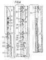
- a whipstockwhich is generally identified by reference numeral 1.
- the whipstock 1comprises a concave 2 comprising a tapered support member 3.
- the front 4 of the tapered support member 4is arcuate and part is provided with a sacrificial bearing 5 of brass.
- the back 6 of the support member 3accommodates a plurality of spacers 7, seven of which are shown. Each spacer 7 is pivotally mounted on the support member 3 by a shaft 8.
- a rod 12projects downwardly from the setting tool assembly 10 and is provided at its lower end with a nut and washer which support a spring 13.
- the spring 13acts against the head 15 of a shear bolt 14 which is slidably mounted on the rod 12.
- the shear bolt 14is threadedly attached to the uppermost member 16 of an actuating linkage which is generally identified by reference numeral 17.
- the uppermost member 16 of the actuating linkage 17is provided with a slot 18 (Fig. 8) which accommodates the shaft of a guide bolt 19.
- the guide bolt 19holds the uppermost member 16 to the concave 2 whilst allowing it to slide relative thereto within the confines of the slot 18.
- the actuating linkage 17further comprises an actuating bar 20 which is pivotally connected to the uppermost member 16 via a short link 21.
- the actuating bar 20is provided with seven elongate slots 23 which are spaced apart along the length of the actuating bar 20 and which accommodate respective studs 22 mounted on each spacer 7.
- a cam pin 24is mounted on the concave 2 just below each spacer 7. Each cam pin 24 rests in a respective cam profile 25 formed in the actuating linkage 17.
- the cam profile 25includes an upper end 26, a lower end 27, and a projection 28 therebetween.
- the whipstock 1is lowered down the casing 9 on the setting tool assembly 10 on a workstring or coil tubing (not shown). It is then set in the casing 9. This operation is more fully described in WO 95/07404.
- the shear bolt 14fails on further upward movement of the setting tool assembly 10 which is then removed leaving the whipstock 1 well supported and ready to receive a starting mill (not shown).
- the recesses 30can simply be bores. However, if the whipstock 1 is to be retrievable the recesses 30 can be shaped so that the detents 29 can be freed.
- a fishing toolis lowered in to the casing 9 and manoeuvred until a hook on the fishing tool engages in an elongate slot (not shown) in the top of the concave 2.
- the spring loaded detents 29will ride out of their respective recesses 30 and the spacers 7 will collapse back to a retracted position.
- the actuating bar 20is about 335cm (11 feet) long.
- the spacers 7increase progressively in length from 5cm (2 inches) at the top to 12.7cm (5 inches) at the bottom and project from the concave 2 by about 1.3cm (0.5 inches) at the top to about 7.6cm (3 inches) at the bottom.
- the length of the spacers 7may be varied so that the concave 2 adopts a predetermined curvature in use. This variant is however not recommended.
- the studs 22could be mounted on the actuating bar 20 and the elongate slots 23 formed in the spacers 7.
- cam pins 24could be mounted on the actuating bar 20 and the cam profiles 25 formed in the tapered support member 3 of the concave 2. However the arrangement described is believed easier to fabricate.
- the embodimentcould be modified so that the spacers 7 are actuated on the application of downward pressure on the setting tool assembly 10.
- the setting toolincluded a starting mill bolted to the whipstock by a shear bolt similar to shear bolt 11. After shearing the shear bolt 11 downward movement of the starting mill would actuate the spacers 7. The starting mill could then be started without the necessity of a separate trip.
- the term "concave”is used to refer to the tapered part of a whipstock regardless of whether the surfaces on which the starting mill bears is arcuate or flat.
Landscapes
- Engineering & Computer Science (AREA)
- Life Sciences & Earth Sciences (AREA)
- Geology (AREA)
- Mining & Mineral Resources (AREA)
- Environmental & Geological Engineering (AREA)
- Fluid Mechanics (AREA)
- Physics & Mathematics (AREA)
- General Life Sciences & Earth Sciences (AREA)
- Geochemistry & Mineralogy (AREA)
- Mechanical Engineering (AREA)
- Soil Sciences (AREA)
- Earth Drilling (AREA)
- Transition And Organic Metals Composition Catalysts For Addition Polymerization (AREA)
- Glass Compositions (AREA)
Description
Claims (7)
- A whipstock (1) having a concave (2) comprising atapered support member (3) which accommodates a pluralityof pivotally mounted spacers (7), and an actuatingbar (20) which co-operates with said spacers (7) topivot them from an inoperative position to an operativeposition in which they project outwardly from saidsupport member (3) by different distances to supportsaid support member (3), characterised in that one ofsaid tapered support member (3) and said actuating bar(20) is provided with a cam pin (24) and the other ofsaid tapered support member (3) and said actuating bar(20) is provided with a cam profile (25) which engagessaid cam pin (24).
- A whipstock as claimed in Claim 1, wherein saidspacers (7) are each provided with one of a stud (22)and an elongated slot (23), and said actuating bar (20)is provided with a plurality of the other of said stud(22) and said elongate slot (23), each said stud (22)projecting into a respective one of said elongate slots(23).
- A whipstock as claimed in Claim 1 or 2, whereinsaid cam profile (25) includes a projection (28).
- A whipstock as claimed in Claim 3, wherein said camprofile (25) comprises a first end (26) and a second end(27) which are disposed to either side of said projection(28).
- A whipstock as claimed in any preceding claim,wherein said actuating bar (20) forms part of an actuatinglinkage (17), said actuating linkage (17) comprisinga member (16) slidably mounted on said concave (2),and a link (21) pivotally mounted to said member (16)and said actuating bar (20) so that said actuating bar(20) can move outwardly from said concave (2).
- A whipstock as claimed in any preceding claim, including a detent (29) for engaging said actuating bar(20) and holding said spacers (7) in their operativeposition.
- A whipstock as claimed in Claim 6, including arecess (30) adapted to receive said detent (29) andshaped so that said detent (29) will withdraw from saidrecess (30) when said whipstock (1) is lifted during arecovery operation.
Applications Claiming Priority (3)
| Application Number | Priority Date | Filing Date | Title |
|---|---|---|---|
| US414201 | 1995-03-31 | ||
| US08/414,201US5531271A (en) | 1993-09-10 | 1995-03-31 | Whipstock side support |
| PCT/GB1996/000788WO1996030622A1 (en) | 1995-03-31 | 1996-04-01 | Whipstock |
Publications (2)
| Publication Number | Publication Date |
|---|---|
| EP0815344A1 EP0815344A1 (en) | 1998-01-07 |
| EP0815344B1true EP0815344B1 (en) | 2000-06-21 |
Family
ID=23640406
Family Applications (1)
| Application Number | Title | Priority Date | Filing Date |
|---|---|---|---|
| EP96908264AExpired - LifetimeEP0815344B1 (en) | 1995-03-31 | 1996-04-01 | Whipstock |
Country Status (6)
| Country | Link |
|---|---|
| US (1) | US5531271A (en) |
| EP (1) | EP0815344B1 (en) |
| AU (1) | AU697695B2 (en) |
| DE (1) | DE69608955T2 (en) |
| NO (1) | NO310483B1 (en) |
| WO (1) | WO1996030622A1 (en) |
Families Citing this family (15)
| Publication number | Priority date | Publication date | Assignee | Title |
|---|---|---|---|---|
| US5887655A (en) | 1993-09-10 | 1999-03-30 | Weatherford/Lamb, Inc | Wellbore milling and drilling |
| US5887668A (en) | 1993-09-10 | 1999-03-30 | Weatherford/Lamb, Inc. | Wellbore milling-- drilling |
| US5765640A (en)* | 1996-03-07 | 1998-06-16 | Baker Hughes Incorporated | Multipurpose tool |
| US6032740A (en)* | 1998-01-23 | 2000-03-07 | Weatherford/Lamb, Inc. | Hook mill systems |
| US6089319A (en)* | 1998-03-23 | 2000-07-18 | Weatherford/Lamb, Inc. | Whipstock |
| US6076606A (en)* | 1998-09-10 | 2000-06-20 | Weatherford/Lamb, Inc. | Through-tubing retrievable whipstock system |
| US6167961B1 (en)* | 1999-05-20 | 2001-01-02 | Tiw Corporation | Small diameter run in whipstock and method for setting in large diameter casing |
| US7353867B2 (en)* | 2002-04-12 | 2008-04-08 | Weatherford/Lamb. Inc. | Whipstock assembly and method of manufacture |
| US6923274B2 (en)* | 2003-01-02 | 2005-08-02 | Weatherford/Lamb, Inc. | Retrievable pre-milled window with deflector |
| US7487835B2 (en)* | 2004-05-20 | 2009-02-10 | Weatherford/Lamb, Inc. | Method of developing a re-entry into a parent wellbore from a lateral wellbore, and bottom hole assembly for milling |
| US10006264B2 (en) | 2014-05-29 | 2018-06-26 | Weatherford Technology Holdings, Llc | Whipstock assembly having anchor and eccentric packer |
| AU2016425343B2 (en) | 2016-09-27 | 2021-09-09 | Halliburton Energy Services, Inc. | Whipstock assemblies with a retractable tension arm |
| US10989042B2 (en)* | 2017-11-22 | 2021-04-27 | Baker Hughes, A Ge Company, Llc | Downhole tool protection cover |
| US11434712B2 (en) | 2018-04-16 | 2022-09-06 | Weatherford Technology Holdings, Llc | Whipstock assembly for forming a window |
| US11608686B2 (en)* | 2021-02-12 | 2023-03-21 | Saudi Arabian Oil Company | Whipstock assemblies and methods for using the same |
Family Cites Families (26)
| Publication number | Priority date | Publication date | Assignee | Title |
|---|---|---|---|---|
| US1816856A (en)* | 1928-10-27 | 1931-08-04 | Kinzbach Frank | Whipstock |
| US1835227A (en)* | 1929-08-05 | 1931-12-08 | Charles H Lane | Whip stock |
| US1951638A (en)* | 1933-01-09 | 1934-03-20 | Clinton L Walker | Deep well whipstock |
| US2014805A (en)* | 1933-05-29 | 1935-09-17 | Frank J Hinderliter | Apparatus for cutting through the side wall of a pipe |
| US2043381A (en)* | 1935-03-09 | 1936-06-09 | Edward K Lane | Automatically orienting whipstock |
| US2170284A (en)* | 1937-10-28 | 1939-08-22 | Eastman Harlan John | Whip-stock bottom |
| US2197344A (en)* | 1939-02-25 | 1940-04-16 | Percy F Matlock | Setting tool |
| US2227347A (en)* | 1939-06-16 | 1940-12-31 | John W Heaston | Whipstock |
| US2362529A (en)* | 1940-08-30 | 1944-11-14 | A 1 Bit And Tool Company Ltd | Side tracking apparatus |
| US2312656A (en)* | 1941-06-28 | 1943-03-02 | Bus Frank L Le | Whipstock deflecting tool |
| US2338788A (en)* | 1941-09-10 | 1944-01-11 | Clinton L Walker | Whipstock |
| US2445100A (en)* | 1944-07-28 | 1948-07-13 | Eastman Oil Well Survey Co | Anchoring means for whipstocks |
| US2509144A (en)* | 1945-08-10 | 1950-05-23 | Donovan B Grable | Well plugging and whipstocking |
| US2633331A (en)* | 1948-09-07 | 1953-03-31 | Hampton Harry | Apparatus for preparing a well casing for sidetrack drilling |
| US2694549A (en)* | 1952-01-21 | 1954-11-16 | Eastman Oil Well Survey Co | Joint structure between flexible shafting and drill bit structure for drilling lateral bores |
| US3602306A (en)* | 1970-04-27 | 1971-08-31 | Gem Tool Corp | Blow-up preventer |
| US3669187A (en)* | 1970-11-25 | 1972-06-13 | Gem Oil Tool Co | Blow-up preventer |
| US4610309A (en)* | 1984-11-30 | 1986-09-09 | Phillips Petroleum Company | Downhole tool |
| US4637471A (en)* | 1985-04-30 | 1987-01-20 | Soderberg Research & Development, Inc. | Tubing drain valve useful with heavy, sand-bearing oil |
| US4733732A (en)* | 1985-08-02 | 1988-03-29 | Atlantic Richfield Company | Submudline drivepipe whipstock method and apparatus |
| US5186254A (en)* | 1989-11-22 | 1993-02-16 | Staden Pieter R Van | Borehole pumping installation |
| US5222554A (en)* | 1992-01-30 | 1993-06-29 | Atlantic Richfield Company | Whipstock for oil and gas wells |
| US5341873A (en)* | 1992-09-16 | 1994-08-30 | Weatherford U.S., Inc. | Method and apparatus for deviated drilling |
| US5425417A (en)* | 1993-09-10 | 1995-06-20 | Weatherford U.S., Inc. | Wellbore tool setting system |
| US5494111A (en)* | 1994-05-13 | 1996-02-27 | Baker Hughes Incorporated | Permanent whipstock |
| US5379845A (en)* | 1994-06-06 | 1995-01-10 | Atlantic Richfield Company | Method for setting a whipstock in a wellbore |
- 1995
- 1995-03-31USUS08/414,201patent/US5531271A/ennot_activeExpired - Lifetime
- 1996
- 1996-04-01WOPCT/GB1996/000788patent/WO1996030622A1/enactiveIP Right Grant
- 1996-04-01DEDE69608955Tpatent/DE69608955T2/ennot_activeExpired - Fee Related
- 1996-04-01EPEP96908264Apatent/EP0815344B1/ennot_activeExpired - Lifetime
- 1996-04-01AUAU51577/96Apatent/AU697695B2/ennot_activeCeased
- 1997
- 1997-09-17NONO19974287Apatent/NO310483B1/ennot_activeIP Right Cessation
Also Published As
| Publication number | Publication date |
|---|---|
| DE69608955D1 (en) | 2000-07-27 |
| AU5157796A (en) | 1996-10-16 |
| NO974287D0 (en) | 1997-09-17 |
| AU697695B2 (en) | 1998-10-15 |
| EP0815344A1 (en) | 1998-01-07 |
| WO1996030622A1 (en) | 1996-10-03 |
| US5531271A (en) | 1996-07-02 |
| DE69608955T2 (en) | 2000-12-28 |
| NO974287L (en) | 1997-11-10 |
| NO310483B1 (en) | 2001-07-09 |
Similar Documents
| Publication | Publication Date | Title |
|---|---|---|
| EP0815344B1 (en) | Whipstock | |
| US5009273A (en) | Deflection apparatus | |
| US3785193A (en) | Liner expanding apparatus | |
| US8286716B2 (en) | Low stress traction system | |
| US5139086A (en) | Double acting accelerator jar | |
| US6012523A (en) | Downhole apparatus and method for expanding a tubing | |
| AU756517B2 (en) | Flexible swage | |
| AU4817693A (en) | Whipstock assembly | |
| US6968903B2 (en) | Orientable whipstock tool and method | |
| US7624797B2 (en) | Downhole tool operated by shape memory material | |
| WO2005108737A1 (en) | Latch mechanism guide | |
| US6550540B2 (en) | Mechanical anchor setting system | |
| US20160290081A1 (en) | High Radial Expansion Anchoring Tool | |
| AU2007201528A1 (en) | Kickover tool and selective mandrel system | |
| CA2216518C (en) | Whipstock | |
| EP2771537A1 (en) | A downhole tool | |
| AU5572196A (en) | Hydraulic shifting tool for sliding sleeves | |
| WO2016182713A1 (en) | Devices and methods for forming bow springs of one-piece centralizers | |
| US4051895A (en) | Positioning tool | |
| US8967243B2 (en) | Kickover tool with ratcheting arm and methods of use | |
| US6899173B2 (en) | Small tubular window system | |
| EP0760417A2 (en) | Method of and apparatus for assembling a tool string | |
| GB2295171A (en) | Bore sealing | |
| WO2008151315A2 (en) | Insert sleeve forming device for a recess shoe | |
| CA2462658C (en) | Through tubing whipstock |
Legal Events
| Date | Code | Title | Description |
|---|---|---|---|
| PUAI | Public reference made under article 153(3) epc to a published international application that has entered the european phase | Free format text:ORIGINAL CODE: 0009012 | |
| 17P | Request for examination filed | Effective date:19970912 | |
| AK | Designated contracting states | Kind code of ref document:A1 Designated state(s):DE FR GB IT NL | |
| RBV | Designated contracting states (corrected) | Designated state(s):DE FR GB IT NL | |
| GRAG | Despatch of communication of intention to grant | Free format text:ORIGINAL CODE: EPIDOS AGRA | |
| 17Q | First examination report despatched | Effective date:19990723 | |
| GRAG | Despatch of communication of intention to grant | Free format text:ORIGINAL CODE: EPIDOS AGRA | |
| GRAH | Despatch of communication of intention to grant a patent | Free format text:ORIGINAL CODE: EPIDOS IGRA | |
| GRAH | Despatch of communication of intention to grant a patent | Free format text:ORIGINAL CODE: EPIDOS IGRA | |
| GRAA | (expected) grant | Free format text:ORIGINAL CODE: 0009210 | |
| AK | Designated contracting states | Kind code of ref document:B1 Designated state(s):DE FR GB IT NL | |
| REF | Corresponds to: | Ref document number:69608955 Country of ref document:DE Date of ref document:20000727 | |
| ITF | It: translation for a ep patent filed | ||
| ET | Fr: translation filed | ||
| PLBE | No opposition filed within time limit | Free format text:ORIGINAL CODE: 0009261 | |
| STAA | Information on the status of an ep patent application or granted ep patent | Free format text:STATUS: NO OPPOSITION FILED WITHIN TIME LIMIT | |
| 26N | No opposition filed | ||
| REG | Reference to a national code | Ref country code:GB Ref legal event code:IF02 | |
| PGFP | Annual fee paid to national office [announced via postgrant information from national office to epo] | Ref country code:FR Payment date:20030408 Year of fee payment:8 | |
| PGFP | Annual fee paid to national office [announced via postgrant information from national office to epo] | Ref country code:DE Payment date:20030409 Year of fee payment:8 | |
| PGFP | Annual fee paid to national office [announced via postgrant information from national office to epo] | Ref country code:NL Payment date:20030429 Year of fee payment:8 | |
| PG25 | Lapsed in a contracting state [announced via postgrant information from national office to epo] | Ref country code:NL Free format text:LAPSE BECAUSE OF NON-PAYMENT OF DUE FEES Effective date:20041101 | |
| PG25 | Lapsed in a contracting state [announced via postgrant information from national office to epo] | Ref country code:DE Free format text:LAPSE BECAUSE OF NON-PAYMENT OF DUE FEES Effective date:20041103 | |
| PG25 | Lapsed in a contracting state [announced via postgrant information from national office to epo] | Ref country code:FR Free format text:LAPSE BECAUSE OF NON-PAYMENT OF DUE FEES Effective date:20041231 | |
| NLV4 | Nl: lapsed or anulled due to non-payment of the annual fee | Effective date:20041101 | |
| REG | Reference to a national code | Ref country code:FR Ref legal event code:ST | |
| PG25 | Lapsed in a contracting state [announced via postgrant information from national office to epo] | Ref country code:IT Free format text:LAPSE BECAUSE OF NON-PAYMENT OF DUE FEES;WARNING: LAPSES OF ITALIAN PATENTS WITH EFFECTIVE DATE BEFORE 2007 MAY HAVE OCCURRED AT ANY TIME BEFORE 2007. THE CORRECT EFFECTIVE DATE MAY BE DIFFERENT FROM THE ONE RECORDED. Effective date:20050401 | |
| PGFP | Annual fee paid to national office [announced via postgrant information from national office to epo] | Ref country code:GB Payment date:20150401 Year of fee payment:20 | |
| REG | Reference to a national code | Ref country code:GB Ref legal event code:732E Free format text:REGISTERED BETWEEN 20151022 AND 20151028 | |
| REG | Reference to a national code | Ref country code:GB Ref legal event code:PE20 Expiry date:20160331 | |
| PG25 | Lapsed in a contracting state [announced via postgrant information from national office to epo] | Ref country code:GB Free format text:LAPSE BECAUSE OF EXPIRATION OF PROTECTION Effective date:20160331 |