EP0813287B1 - Switched reluctance motors - Google Patents
Switched reluctance motorsDownload PDFInfo
- Publication number
- EP0813287B1 EP0813287B1EP97304084AEP97304084AEP0813287B1EP 0813287 B1EP0813287 B1EP 0813287B1EP 97304084 AEP97304084 AEP 97304084AEP 97304084 AEP97304084 AEP 97304084AEP 0813287 B1EP0813287 B1EP 0813287B1
- Authority
- EP
- European Patent Office
- Prior art keywords
- pole
- rotor
- magnetic
- switched reluctance
- weak
- Prior art date
- Legal status (The legal status is an assumption and is not a legal conclusion. Google has not performed a legal analysis and makes no representation as to the accuracy of the status listed.)
- Expired - Lifetime
Links
- 239000000463materialSubstances0.000claimsdescription4
- 230000004907fluxEffects0.000description6
- 238000004804windingMethods0.000description4
- 229910000831SteelInorganic materials0.000description3
- 239000010959steelSubstances0.000description3
- XEEYBQQBJWHFJM-UHFFFAOYSA-NIronChemical compound[Fe]XEEYBQQBJWHFJM-UHFFFAOYSA-N0.000description2
- 230000007423decreaseEffects0.000description2
- 230000002093peripheral effectEffects0.000description2
- 239000012141concentrateSubstances0.000description1
- 238000010276constructionMethods0.000description1
- 230000000694effectsEffects0.000description1
- 229910052742ironInorganic materials0.000description1
- 238000005259measurementMethods0.000description1
Images


Classifications
- H—ELECTRICITY
- H02—GENERATION; CONVERSION OR DISTRIBUTION OF ELECTRIC POWER
- H02K—DYNAMO-ELECTRIC MACHINES
- H02K19/00—Synchronous motors or generators
- H02K19/02—Synchronous motors
- H02K19/10—Synchronous motors for multi-phase current
- H02K19/103—Motors having windings on the stator and a variable reluctance soft-iron rotor without windings
- H—ELECTRICITY
- H02—GENERATION; CONVERSION OR DISTRIBUTION OF ELECTRIC POWER
- H02K—DYNAMO-ELECTRIC MACHINES
- H02K29/00—Motors or generators having non-mechanical commutating devices, e.g. discharge tubes or semiconductor devices
- H02K29/03—Motors or generators having non-mechanical commutating devices, e.g. discharge tubes or semiconductor devices with a magnetic circuit specially adapted for avoiding torque ripples or self-starting problems
Definitions
- the inventionrelates to switched reluctance motors which are operated mainly in one rotational direction, and are suitable as a power source of an electric vehicle.
- a typical switched reluctance motorhas a ring-like stator with pole portions in a cylindrical arrangement and is provided with coil windings.
- a rotoris inside the stator and provided with poles facing the pole portions of the stator.
- the rotornormally comprises a core formed of a stack of iron or steel plates.
- the coils and pole portionsact as electromagnets to attract the rotor poles.
- This type of motoris disclosed in, for example JP Laid Open Sho 48(1973)-77314, JP Laid-Open Sho 61(1986)-203847 and US 3,956,678.
- WO-A-8606891discloses a reluctance motor comprising a stator having two salient poles and a rotor also having two poles.
- the poles of the stator and the poles of the rotorare each provided with a recess so that the motor can rotate in the desired direction even from a start-up position wherein the stator poles completely coincide with the rotor poles.
- a weak or non-magnetic portion in each of the rotor polesextends inward and in the rotational direction from a position close to an outer end of the pole and at the side of the pole facing in the direction of counter-rotation wherein the weak or non-magnetic portion (15) extends radially inward from a position close to a radially outer end of the pole (14).
- the weak or non-magnetic portionmay be in the form of a groove which may contain non-magnetic high-electric resistance material or be in the form of a hole.
- the said portionmay have a side which extends radially inward.
- the groovemay be elongated and rounded-ended or elliptical for example.
- the numbers of stator and rotor polesmay be 12 and 8 or 6 and 4 respectively for example.
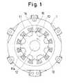
- the motor 1has twelve pole portions in a stator 11 and eight projected poles in a rotor 10.
- the stator 11is formed of a stack of annular magnetic steel plates, and has pole portions 11a extending axially of the stator 11 and projecting from the inner peripheral face so that a pair are located opposite each other.
- the stator 11is fixed by thermally fitting an outer peripheral portion into a hollow portion of a housing.
- Six pairs of oppositely-disposed pole portions llaare divided into three groups of two pairs, and the pole portions 11a of each group are provided with interconnected coil windings 13, thereby forming a three-phase construction.
- the rotor 10is formed of a stack of magnetic steel plates and has a central hole in which a shaft 12 is fixed.
- the shaft 12is rotatably supported on side housings (not shown) by bearings.
- the rotor 10is thus rotatable with the shaft 12 inside the stator 11.
- the rotor 10has four pairs of poles 14 equidistantly spaced so that each pair projects radially outward in opposite directions.
- the poles 14extend in the direction of the axis of the rotor 10. When the poles 14 face the pole portions lla during rotation of the rotor 10, each pole 14 maintains a predetermined clearance from the facing pole portion lla as can be seen in Fig. 1.
- the rotor 10rotates counter-clockwise.
- Each pole 14has a weak-magnetic portion 15 provided at a radially outer end near or at a side facing in the clockwise direction, i.e., the direction opposite to the rotational direction.
- the weak-magnetic portion 15 of each pole 14bis an elongated, rounded-ended groove 15b extending from a point E relatively close to a radially outer end of the pole 14b at an end facing in the clockwise direction, i.e., the counter-rotational direction.
- the groove 15bextends to a point F relatively close to a radially inner end of the pole 14b at an end facing in the counter-clockwise direction, i.e., the rotational direction.
- each weak-magnetic portion 15is in the form of a generally triangular hole 15a that has a side D extending from a point E relatively close to a radially outer end of the pole 14a at a side facing in the clockwise direction, i.e., the counter-rotational direction.
- the side D of the triangular hole 15aextends inwardly and in the direction of rotation from the point E to a point F.
- the corners of the triangular holes 15aare rounded.
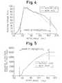
- a rotor angle of 0°is defined at a position of the rotor 10 at which a pole portion lla of the stator 11 is at a mid point between two neighbouring poles 14. Therefore, the position of the rotor 10 where a pole 14 exactly aligns with or faces the pole portion 11a is 22.5°.
- the solid-line and broken-line curves in Figs. 4 and 5indicate a conventional reluctance motor (without a hole) and a switched reluctance motor according to the invention (with holes).
- the torque and the magnetic forceincrease with rotation of the rotor 10 from when a rotational direction-facing end portion of a pole 14 overlaps an end portion of a pole portion lla to when the weak-magnetic portion 15 overlaps (faces) the pole portion lla, since the pole 14 is not blocked or interfered with by the weak-magnetic portion 15 during that period.
- the torquereaches a peak before the weak-magnetic portion 15 overlaps (faces) the pole portion lla and then gradually decreases as the torque is produced by a component of the magnetic force on the pole 14.
- the magnetic attraction forceincreases as the areas of the pole 14 and the pole portion 11 that face each other increases with rotation of the rotor 10, as indicated in Fig. 5.
- the increase of the magnetic flux contributing to an increase of the magnetic attraction forceis curbed by the weak-magnetic portion 15.
- the magnetic flux in the pole 14is blocked by the weak-magnetic portion 15, thus curbing the increase of the magnetic force.
- the magnetic force at the time of energization switchingis thereby reduced to about 4250 kgf from a conventional value of about 5000 kgf.
- the torqueis mainly determined by a component of the magnetic force between a rotational direction-facing end portion of the pole 14 and an end portion of the pole portion 11a. Since the weak-magnetic portion 15 has a shape as shown in Figs. 2 and 3, the portion 15 does not significantly reduce the magnetic flux component that causes the pole 14 to move to face the pole portion lla. Therefore, the curb on the increase of the magnetic force achieved does not involve a significant reduction in the torque.
- the torquedecreases by only a few percent from the torque produced by the conventional motor. In Fig. 4, that torque is within the range of energization.
- the magnetic force at the time of switching the coils 13 to be energizedis reduced while maintaining generation of a desired amount of torque. The necessary torque is thus produced without increasing the number of winding turns of the coils 13.
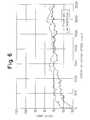
- Fig. 6shows that the invention reduces noises over the entire operation range. During the noise measurement indicated in Fig. 6, it was confirmed that the difference between the power inputs to conventional motors and according to the invention was small, and the torque reduction correspondingly small.
- the weak-magnetic portion 15contains a non-magnetic high-electric resistant material, the strength of the rotor 10 will be increased. It is also possible to adjust rotational imbalances of the rotor 10 by means of such materials. It also reduces the effect of eddy currents in the rotor 10.
Landscapes
- Engineering & Computer Science (AREA)
- Power Engineering (AREA)
- Synchronous Machinery (AREA)
- Motor Or Generator Frames (AREA)
Description
- The invention relates to switched reluctance motors whichare operated mainly in one rotational direction, and aresuitable as a power source of an electric vehicle.
- A typical switched reluctance motor has a ring-like statorwith pole portions in a cylindrical arrangement and isprovided with coil windings. A rotor is inside the statorand provided with poles facing the pole portions of thestator. The rotor normally comprises a core formed of astack of iron or steel plates. The coils and poleportions act as electromagnets to attract the rotor poles.This type of motor is disclosed in, for example JP LaidOpen Sho 48(1973)-77314, JP Laid-Open Sho 61(1986)-203847and US 3,956,678.
- Such motors, which generate torque from magnetic forcesbetween the rotor poles and the stator by energization ofthe coils, normally produce considerable vibration. Thisis because in each cycle of energization the radialmagnetic force increases with rotation of the rotor,reaches a maximum and abruptly discontinues onenergization switching. The above US Patent incorporatesslits formed on the side of the rotor poles facing in therotational direction of the rotor. This considerablyreduces the torque output.
- WO-A-8606891, discloses a reluctance motor comprising astator having two salient poles and a rotor also havingtwo poles. The poles of the stator and the poles of therotor are each provided with a recess so that the motorcan rotate in the desired direction even from a start-upposition wherein the stator poles completely coincide withthe rotor poles.
- According to the invention a weak or non-magnetic portionin each of the rotor poles extends inward and in therotational direction from a position close to an outer endof the pole and at the side of the pole facing in thedirection of counter-rotation wherein the weak or non-magnetic portion (15) extends radially inward from a position close to a radially outer end of the pole (14). This reduces the magneticforce at the time of energization switching in a simplemanner and ensures generation of a desired amount oftorque.
- The weak or non-magnetic portion may be in the form of agroove which may contain non-magnetic high-electricresistance material or be in the form of a hole. The saidportion may have a side which extends radially inward.The groove may be elongated and rounded-ended orelliptical for example. The numbers of stator and rotorpoles may be 12 and 8 or 6 and 4 respectively for example.
- In operation, up to the moment when a rotationaldirection-facing end portion of a rotor pole overlaps(faces) an end portion of a stator pole portion, magneticflux concentrates in the end portions of the rotor andthe stator, producing a torque and a magnetic attractionregardless of any weak or non-magnetic portion. Onfurther rotation, the rotor pole overlaps the stator poleportion that is the pole areas facing each other increase,and the magnetic attraction increases. However, theincrease in the magnetic flux contributing to the increasein the magnetic attraction force is curbed by the weak ornon-magnetic portion. Therefore, when acounter-rotational direction-facing end portion of therotor pole overlaps the end of the stator pole portion,the magnetic flux extending through the rotor pole isblocked or interfered with. Increase in the magneticattraction force is thereby curbed. Since the force(torque) to rotate the rotor is determined mainly by themagnetic force between a rotational direction-facing endof the rotor pole and an end of the stator pole portionthe curb on the increase in the magnetic force provided bythe weak or non-magnetic portion does not remarkablyreduce the torque.
- Fig. 1 is a cross-section through a first switchedreluctance motor according to the invention;
- Fig. 2 is an elevation of a rotor in Fig. 1;
- Fig. 3 is an elevation of a rotor according to a secondswitched reluctance motor according to the invention;
- Fig. 4 shows the relationship of the torque to the rotorangle of a switched reluctance motor according to theinvention and of a conventional motor;
- Fig. 5 shows the relationship of the magnetic force to therotor angle of a switched reluctance motor according tothe invention and of a conventional motor; and
- Fig. 6 shows the relationship of the noise to the motoroperating speed of a switched reluctance motor accordingto the invention and of a conventional motor.
- With particular reference to Fig. 1, the
motor 1 hastwelve pole portions in astator 11 and eight projectedpoles in arotor 10. Thestator 11 is formed of a stackof annular magnetic steel plates, and haspole portions 11a extending axially of thestator 11 and projecting fromthe inner peripheral face so that a pair are locatedopposite each other. Thestator 11 is fixed by thermallyfitting an outer peripheral portion into a hollow portionof a housing. Six pairs of oppositely-disposed poleportions lla are divided into three groups of two pairs,and thepole portions 11a of each group are provided withinterconnectedcoil windings 13, thereby forming athree-phase construction. - The
rotor 10 is formed of a stack of magnetic steel platesand has a central hole in which ashaft 12 is fixed. Theshaft 12 is rotatably supported on side housings (notshown) by bearings. Therotor 10 is thus rotatable withtheshaft 12 inside thestator 11. Therotor 10 has fourpairs ofpoles 14 equidistantly spaced so that each pairprojects radially outward in opposite directions. Thepoles 14 extend in the direction of the axis of therotor 10. When thepoles 14 face the pole portions lla duringrotation of therotor 10, eachpole 14 maintains apredetermined clearance from the facing pole portion llaas can be seen in Fig. 1. Therotor 10 rotates counter-clockwise. Eachpole 14 has a weak-magneticportion 15 provided at a radially outer end near or at aside facing in the clockwise direction, i.e., thedirection opposite to the rotational direction. - In Fig. 2, the weak-
magnetic portion 15 of eachpole 14bis an elongated, rounded-ended groove 15b extending from apoint E relatively close to a radially outer end of thepole 14b at an end facing in the clockwise direction,i.e., the counter-rotational direction. Thegroove 15bextends to a point F relatively close to a radially innerend of thepole 14b at an end facing in thecounter-clockwise direction, i.e., the rotationaldirection. - In Fig. 3, each weak-
magnetic portion 15 is in the form ofa generallytriangular hole 15a that has a side Dextending from a point E relatively close to a radiallyouter end of the pole 14a at a side facing in theclockwise direction, i.e., the counter-rotationaldirection. The side D of thetriangular hole 15a extendsinwardly and in the direction of rotation from the point Eto a point F. The corners of thetriangular holes 15a arerounded. - When a
coil 13 is energized, there is magnetic attractionbetweenadjacent poles 14 and pole portions lla. Due to acomponent of the magnetic force, torque acts on therotor 10 and thepole 14 faces the pole portion lla. Byswitching energization of thecoils 13, torquescontinually act on therotor 10, thereby continuingrotation of therotor 10. - In the graphs of Figs. 4 and 5, a rotor angle of 0° isdefined at a position of the
rotor 10 at which a poleportion lla of thestator 11 is at a mid point between twoneighbouringpoles 14. Therefore, the position of therotor 10 where apole 14 exactly aligns with or faces thepole portion 11a is 22.5°. The solid-line and broken-linecurves in Figs. 4 and 5 indicate a conventional reluctancemotor (without a hole) and a switched reluctance motoraccording to the invention (with holes). - The torque and the magnetic force increase with rotationof the
rotor 10 from when a rotational direction-facingend portion of apole 14 overlaps an end portion of a poleportion lla to when the weak-magnetic portion 15 overlaps(faces) the pole portion lla, since thepole 14 is notblocked or interfered with by the weak-magnetic portion 15during that period. The torque reaches a peak before theweak-magnetic portion 15 overlaps (faces) the pole portionlla and then gradually decreases as the torque is producedby a component of the magnetic force on thepole 14. - The magnetic attraction force increases as the areas ofthe
pole 14 and thepole portion 11 that face each otherincreases with rotation of therotor 10, as indicated inFig. 5. However, the increase of the magnetic fluxcontributing to an increase of the magnetic attractionforce is curbed by the weak-magnetic portion 15. When acounter-rotational direction-facing end portion of thepole 14 overlaps an end portion of thepole portion 11a ofthestator 11, the magnetic flux in thepole 14 is blockedby the weak-magnetic portion 15, thus curbing the increaseof the magnetic force. The magnetic force at the time ofenergization switching is thereby reduced to about 4250kgf from a conventional value of about 5000 kgf. Thetorque is mainly determined by a component of the magneticforce between a rotational direction-facing end portion ofthepole 14 and an end portion of thepole portion 11a.Since the weak-magnetic portion 15 has a shape as shown inFigs. 2 and 3, theportion 15 does not significantlyreduce the magnetic flux component that causes thepole 14to move to face the pole portion lla. Therefore, the curbon the increase of the magnetic force achieved does notinvolve a significant reduction in the torque. The torque decreases by only a few percent from the torque producedby the conventional motor. In Fig. 4, that torque iswithin the range of energization. Thus the magnetic forceat the time of switching thecoils 13 to be energized isreduced while maintaining generation of a desired amountof torque. The necessary torque is thus produced withoutincreasing the number of winding turns of thecoils 13. - Increasing the number of winding turns would increaseweight and cost. The reduction of the maximum magneticforce at the time of energization switching restrains thegeneration of noise resulting from vibrations produced.The graph of Fig. 6 shows that the invention reducesnoises over the entire operation range. During the noisemeasurement indicated in Fig. 6, it was confirmed that thedifference between the power inputs to conventional motorsand according to the invention was small, and the torquereduction correspondingly small.
- If the weak-
magnetic portion 15 contains a non-magnetichigh-electric resistant material, the strength of therotor 10 will be increased. It is also possible to adjustrotational imbalances of therotor 10 by means of suchmaterials. It also reduces the effect of eddy currents intherotor 10.
Claims (6)
- A switched reluctance motor comprising:a stator (11) having pole portions (lla) extendingaxially and projecting inward in radially-opposed pairs;a rotor (10) having poles (14) extending axially andprojecting outward towards the stator pole portions (11a) ;andcoils (13) wound around the pole portions (lla)whereina weak or non-magnetic portion (15) is provided ineach of the rotor poles (14) extending in the rotationaldirection from the side of the pole (14) facing in thedirection of counter-rotation characterized in that theweak or non-magnetic portion (15) extends radially inwardfrom a position close to a radially outer end of the pole(14).
- A switched reluctance motor according to claim 1 inwhich the rotor (10) is formed of a stack of plates.
- A switched reluctance motor according to anypreceding claim in which the weak or non-magnetic portion(15) contains non-magnetic high-electric resistancematerial.
- A switched reluctance motor according to anypreceding claim in which the weak or non-magnetic portion(15) is in the form of a groove.
- A switched reluctance motor according to any ofclaims 1 to 3 in which the portion (15) is in the form ofa hole.
- A switched reluctance motor according to claim 5 inwhich the hole has a side extending radially inward.
Applications Claiming Priority (3)
| Application Number | Priority Date | Filing Date | Title |
|---|---|---|---|
| JP149184/96 | 1996-06-11 | ||
| JP14918496AJP3633106B2 (en) | 1996-06-11 | 1996-06-11 | Switched reluctance motor |
| JP14918496 | 1996-06-11 |
Publications (3)
| Publication Number | Publication Date |
|---|---|
| EP0813287A2 EP0813287A2 (en) | 1997-12-17 |
| EP0813287A3 EP0813287A3 (en) | 1998-02-11 |
| EP0813287B1true EP0813287B1 (en) | 2000-11-22 |
Family
ID=15469642
Family Applications (1)
| Application Number | Title | Priority Date | Filing Date |
|---|---|---|---|
| EP97304084AExpired - LifetimeEP0813287B1 (en) | 1996-06-11 | 1997-06-11 | Switched reluctance motors |
Country Status (4)
| Country | Link |
|---|---|
| US (1) | US5917263A (en) |
| EP (1) | EP0813287B1 (en) |
| JP (1) | JP3633106B2 (en) |
| DE (1) | DE69703566T2 (en) |
Families Citing this family (24)
| Publication number | Priority date | Publication date | Assignee | Title |
|---|---|---|---|---|
| GB9801187D0 (en)* | 1998-01-20 | 1998-03-18 | Switched Reluctance Drives Ltd | Noise reduction in reluctance machines |
| FR2784518B1 (en)* | 1998-10-12 | 2000-12-29 | Valeo Equip Electr Moteur | ROTATING ELECTRIC MACHINE, PARTICULARLY A MOTOR VEHICLE ALTERNATOR, HAVING IMPROVED NOISE REDUCTION MEANS |
| US6483212B1 (en)* | 1999-10-06 | 2002-11-19 | Asmo Co., Ltd. | Reluctance-type electric motor |
| US6891299B2 (en)* | 2000-05-03 | 2005-05-10 | Moteurs Leroy-Somer | Rotary electric machine having a flux-concentrating rotor and a stator with windings on teeth |
| JP4797227B2 (en)* | 2000-06-14 | 2011-10-19 | ダイキン工業株式会社 | Switched reluctance motor |
| US6777844B2 (en)* | 2000-10-24 | 2004-08-17 | Rexair, Inc. | Brushless motor |
| KR100390502B1 (en)* | 2000-12-30 | 2003-07-07 | 엘지전자 주식회사 | Structure of reluctance motor for noise reduction |
| US20020171305A1 (en)* | 2001-04-17 | 2002-11-21 | Moteurs Leroy-Somer | Electric machine having an outer rotor |
| FR2823614B1 (en)* | 2001-04-17 | 2008-07-11 | Leroy Somer Moteurs | ELECTRICAL ROTATING MACHINE HAVING A STATOR FORM OF ASSEMBLED SECTORS |
| US7420308B2 (en)* | 2002-05-24 | 2008-09-02 | Virginia Tech Intellectual Properties, Inc. | PMBDCM and two phase SRM motor, two phase SRM rotor and stator, and coil wrap for PMBDCM and SRM motors |
| US6727618B1 (en) | 2002-06-10 | 2004-04-27 | The United States Of America, As Represented By The Administrator Of National Aeronautics And Space Administration | Bearingless switched reluctance motor |
| KR100437189B1 (en)* | 2002-08-28 | 2004-06-23 | 전자부품연구원 | Switched Reluctance Motor with flux barrier |
| JP4581640B2 (en)* | 2004-11-17 | 2010-11-17 | トヨタ自動車株式会社 | Vehicle drive system and vehicle equipped with the same |
| KR100677285B1 (en)* | 2005-07-11 | 2007-02-02 | 엘지전자 주식회사 | Switched reluctance motor |
| FR2893772B1 (en)* | 2005-11-18 | 2008-09-19 | Peugeot Citroen Automobiles Sa | ARRANGEMENT OF THE POLES OF THE ROTOR OF AN ELECTRIC MACHINE AND ELECTRIC MACHINE WITH SUCH ARRANGEMENT OF POLES. |
| US20110062805A1 (en)* | 2009-09-17 | 2011-03-17 | Caterpillar Inc. | Switched reluctance machine with eddy current loss dampener |
| US8736136B2 (en)* | 2011-02-16 | 2014-05-27 | Toyota Motor Engineering & Manufacturing North America, Inc. | Magnetic field manipulation in switched reluctance motors and design method |
| WO2015142084A1 (en)* | 2014-03-20 | 2015-09-24 | 구제현 | Direct current motor and generator |
| GB2527101B (en)* | 2014-06-12 | 2016-10-19 | Jaguar Land Rover Ltd | A switched reluctance motor with reduced torque ripple |
| ES2784177T3 (en)* | 2014-08-05 | 2020-09-22 | Ego Elektro Geraetebau Gmbh | Household appliance |
| CN107800205A (en)* | 2017-11-28 | 2018-03-13 | 深圳市优必选科技有限公司 | Motor chip and motor |
| JP7636859B2 (en)* | 2019-04-18 | 2025-02-27 | 三星電子株式会社 | Drive motor |
| KR102300921B1 (en)* | 2019-12-19 | 2021-09-09 | 경성대학교 산학협력단 | Improved Radial Force Reduction Switched Reluctance Motor |
| KR102374803B1 (en)* | 2019-12-19 | 2022-03-15 | 경성대학교 산학협력단 | Radial Force Reduction Switched Reluctance Motor |
Family Cites Families (6)
| Publication number | Priority date | Publication date | Assignee | Title |
|---|---|---|---|---|
| JPS58157358A (en)* | 1982-03-10 | 1983-09-19 | Japan Servo Co Ltd | Dc brushless motor |
| SE447857B (en)* | 1985-05-09 | 1986-12-15 | Electrolux Ab | RELUCTION ENGINE RELUCTION ENGINE |
| JPH05316701A (en)* | 1992-05-13 | 1993-11-26 | Mitsubishi Heavy Ind Ltd | Reluctance motor |
| DE4345599B4 (en)* | 1993-03-01 | 2006-11-30 | Papst Licensing Gmbh & Co. Kg | electric motor |
| JPH06261509A (en)* | 1993-03-04 | 1994-09-16 | Akira Ishizaki | Reluctance rotating machine |
| JP2978057B2 (en)* | 1994-06-07 | 1999-11-15 | 株式会社東芝 | Permanent magnet type motor and compressor for cooling system |
- 1996
- 1996-06-11JPJP14918496Apatent/JP3633106B2/ennot_activeExpired - Fee Related
- 1997
- 1997-06-11DEDE69703566Tpatent/DE69703566T2/ennot_activeExpired - Fee Related
- 1997-06-11USUS08/873,193patent/US5917263A/ennot_activeExpired - Fee Related
- 1997-06-11EPEP97304084Apatent/EP0813287B1/ennot_activeExpired - Lifetime
Also Published As
| Publication number | Publication date |
|---|---|
| EP0813287A3 (en) | 1998-02-11 |
| JP3633106B2 (en) | 2005-03-30 |
| US5917263A (en) | 1999-06-29 |
| DE69703566T2 (en) | 2001-05-31 |
| DE69703566D1 (en) | 2000-12-28 |
| EP0813287A2 (en) | 1997-12-17 |
| JPH09331663A (en) | 1997-12-22 |
Similar Documents
| Publication | Publication Date | Title |
|---|---|---|
| EP0813287B1 (en) | Switched reluctance motors | |
| US8816554B2 (en) | Motor | |
| US7576465B2 (en) | Dual rotor electromagnetic machine | |
| US5811904A (en) | Permanent magnet dynamo electric machine | |
| KR100899913B1 (en) | Motor | |
| EP1990895B1 (en) | Stress distributing permanent magnet rotor geometry for electric machines | |
| WO2009081766A1 (en) | Motor and rotor for dynamo-electric machine | |
| JP2002204541A (en) | Permanent magnet type rotary motor | |
| CN108696019B (en) | End plate for rotor of switched reluctance motor | |
| US7692354B2 (en) | Rotary electric machine with reduced torque ripple | |
| US20110163641A1 (en) | Permanent-magnet synchronous motor | |
| US20120098378A1 (en) | Motor | |
| US5744893A (en) | Brushless motor stator design | |
| JPH10164779A (en) | Axial gap synchronous machine | |
| US20250096628A1 (en) | Variable torque constant electric machines having a radial spoked rotor with axial flux magnet plates and methods thereof | |
| KR100912637B1 (en) | Rotary and electromagnetic machines | |
| JP4604565B2 (en) | Rotor and rotating electric machine equipped with the same | |
| CN110431727A (en) | Electric motor with a converter element in the magnetic circuit | |
| JP2020137350A (en) | Axial gap motor | |
| JP4556408B2 (en) | Claw pole type rotating machine | |
| JP2012080616A (en) | Variable flux motor | |
| JP7727569B2 (en) | rotating electrical machines | |
| JP4680980B2 (en) | Electric motor | |
| JP4862344B2 (en) | Rotating electric machine | |
| KR20200014040A (en) | Motor of motch structure for torque ripple |
Legal Events
| Date | Code | Title | Description |
|---|---|---|---|
| PUAI | Public reference made under article 153(3) epc to a published international application that has entered the european phase | Free format text:ORIGINAL CODE: 0009012 | |
| AK | Designated contracting states | Kind code of ref document:A2 Designated state(s):DE FR GB | |
| PUAL | Search report despatched | Free format text:ORIGINAL CODE: 0009013 | |
| AK | Designated contracting states | Kind code of ref document:A3 Designated state(s):AT BE CH DE DK ES FI FR GB GR IE IT LI LU MC NL PT SE | |
| 17P | Request for examination filed | Effective date:19980112 | |
| AKX | Designation fees paid | Free format text:DE FR GB | |
| RBV | Designated contracting states (corrected) | Designated state(s):DE FR GB | |
| 17Q | First examination report despatched | Effective date:19990326 | |
| GRAG | Despatch of communication of intention to grant | Free format text:ORIGINAL CODE: EPIDOS AGRA | |
| 17Q | First examination report despatched | Effective date:19990326 | |
| GRAG | Despatch of communication of intention to grant | Free format text:ORIGINAL CODE: EPIDOS AGRA | |
| GRAH | Despatch of communication of intention to grant a patent | Free format text:ORIGINAL CODE: EPIDOS IGRA | |
| GRAH | Despatch of communication of intention to grant a patent | Free format text:ORIGINAL CODE: EPIDOS IGRA | |
| GRAA | (expected) grant | Free format text:ORIGINAL CODE: 0009210 | |
| AK | Designated contracting states | Kind code of ref document:B1 Designated state(s):DE FR GB | |
| REF | Corresponds to: | Ref document number:69703566 Country of ref document:DE Date of ref document:20001228 | |
| ET | Fr: translation filed | ||
| PLBE | No opposition filed within time limit | Free format text:ORIGINAL CODE: 0009261 | |
| STAA | Information on the status of an ep patent application or granted ep patent | Free format text:STATUS: NO OPPOSITION FILED WITHIN TIME LIMIT | |
| 26N | No opposition filed | ||
| REG | Reference to a national code | Ref country code:GB Ref legal event code:IF02 | |
| PGFP | Annual fee paid to national office [announced via postgrant information from national office to epo] | Ref country code:FR Payment date:20030610 Year of fee payment:7 | |
| PGFP | Annual fee paid to national office [announced via postgrant information from national office to epo] | Ref country code:GB Payment date:20030611 Year of fee payment:7 | |
| PGFP | Annual fee paid to national office [announced via postgrant information from national office to epo] | Ref country code:DE Payment date:20030618 Year of fee payment:7 | |
| PG25 | Lapsed in a contracting state [announced via postgrant information from national office to epo] | Ref country code:GB Free format text:LAPSE BECAUSE OF NON-PAYMENT OF DUE FEES Effective date:20040611 | |
| PG25 | Lapsed in a contracting state [announced via postgrant information from national office to epo] | Ref country code:DE Free format text:LAPSE BECAUSE OF NON-PAYMENT OF DUE FEES Effective date:20050101 | |
| GBPC | Gb: european patent ceased through non-payment of renewal fee | Effective date:20040611 | |
| PG25 | Lapsed in a contracting state [announced via postgrant information from national office to epo] | Ref country code:FR Free format text:LAPSE BECAUSE OF NON-PAYMENT OF DUE FEES Effective date:20050228 | |
| REG | Reference to a national code | Ref country code:FR Ref legal event code:ST |