EP0812218B1 - Locking package for a syringe - Google Patents
Locking package for a syringeDownload PDFInfo
- Publication number
- EP0812218B1 EP0812218B1EP96905242AEP96905242AEP0812218B1EP 0812218 B1EP0812218 B1EP 0812218B1EP 96905242 AEP96905242 AEP 96905242AEP 96905242 AEP96905242 AEP 96905242AEP 0812218 B1EP0812218 B1EP 0812218B1
- Authority
- EP
- European Patent Office
- Prior art keywords
- key
- cover members
- container according
- syringe
- cover member
- Prior art date
- Legal status (The legal status is an assumption and is not a legal conclusion. Google has not performed a legal analysis and makes no representation as to the accuracy of the status listed.)
- Expired - Lifetime
Links
- 239000003708ampulSubstances0.000description7
- 239000011324beadSubstances0.000description7
- 208000030507AIDSDiseases0.000description2
- 230000001154acute effectEffects0.000description1
- 239000008280bloodSubstances0.000description1
- 210000004369bloodAnatomy0.000description1
- 238000010276constructionMethods0.000description1
- 239000003814drugSubstances0.000description1
- 229940079593drugDrugs0.000description1
- 208000006454hepatitisDiseases0.000description1
- 231100000283hepatitisToxicity0.000description1
- 230000008676importEffects0.000description1
- 239000000463materialSubstances0.000description1
- 230000004048modificationEffects0.000description1
- 238000012986modificationMethods0.000description1
- 230000000737periodic effectEffects0.000description1
- 230000008707rearrangementEffects0.000description1
- 238000000926separation methodMethods0.000description1
Images
Classifications
- B—PERFORMING OPERATIONS; TRANSPORTING
- B65—CONVEYING; PACKING; STORING; HANDLING THIN OR FILAMENTARY MATERIAL
- B65D—CONTAINERS FOR STORAGE OR TRANSPORT OF ARTICLES OR MATERIALS, e.g. BAGS, BARRELS, BOTTLES, BOXES, CANS, CARTONS, CRATES, DRUMS, JARS, TANKS, HOPPERS, FORWARDING CONTAINERS; ACCESSORIES, CLOSURES, OR FITTINGS THEREFOR; PACKAGING ELEMENTS; PACKAGES
- B65D55/00—Accessories for container closures not otherwise provided for
- B65D55/02—Locking devices; Means for discouraging or indicating unauthorised opening or removal of closure
- B65D55/14—Applications of locks, e.g. of permutation or key-controlled locks
- A—HUMAN NECESSITIES
- A61—MEDICAL OR VETERINARY SCIENCE; HYGIENE
- A61M—DEVICES FOR INTRODUCING MEDIA INTO, OR ONTO, THE BODY; DEVICES FOR TRANSDUCING BODY MEDIA OR FOR TAKING MEDIA FROM THE BODY; DEVICES FOR PRODUCING OR ENDING SLEEP OR STUPOR
- A61M5/00—Devices for bringing media into the body in a subcutaneous, intra-vascular or intramuscular way; Accessories therefor, e.g. filling or cleaning devices, arm-rests
- A61M5/002—Packages specially adapted therefor, e.g. for syringes or needles, kits for diabetics
- A61M5/003—Kits for diabetics
- B—PERFORMING OPERATIONS; TRANSPORTING
- B65—CONVEYING; PACKING; STORING; HANDLING THIN OR FILAMENTARY MATERIAL
- B65D—CONTAINERS FOR STORAGE OR TRANSPORT OF ARTICLES OR MATERIALS, e.g. BAGS, BARRELS, BOTTLES, BOXES, CANS, CARTONS, CRATES, DRUMS, JARS, TANKS, HOPPERS, FORWARDING CONTAINERS; ACCESSORIES, CLOSURES, OR FITTINGS THEREFOR; PACKAGING ELEMENTS; PACKAGES
- B65D25/00—Details of other kinds or types of rigid or semi-rigid containers
- B65D25/02—Internal fittings
- B65D25/10—Devices to locate articles in containers
- B65D25/103—V-shaped elements, e.g. racks, protuberances projecting from a supporting surface, supporting the articles locally at its sides
- Y—GENERAL TAGGING OF NEW TECHNOLOGICAL DEVELOPMENTS; GENERAL TAGGING OF CROSS-SECTIONAL TECHNOLOGIES SPANNING OVER SEVERAL SECTIONS OF THE IPC; TECHNICAL SUBJECTS COVERED BY FORMER USPC CROSS-REFERENCE ART COLLECTIONS [XRACs] AND DIGESTS
- Y10—TECHNICAL SUBJECTS COVERED BY FORMER USPC
- Y10T—TECHNICAL SUBJECTS COVERED BY FORMER US CLASSIFICATION
- Y10T70/00—Locks
- Y10T70/50—Special application
- Y10T70/5009—For portable articles
- Y10T70/5031—Receptacle
Definitions
- This inventionrelates to a locking container and, more particularly, to a locking container adapted for use in holding a syringe, an ampoule and a locking key, the locking key being used to lock the locking container in the closed condition after the placement therein of a used syringe.
- a locking package or containerhaving a pair of cover members hingedly interrelated and movable between open and closed positions to permit access to a syringe receiving cavity located between the cover members, which cover members have structure thereon adapted to receive a locking key therein to lock the two cover members together in the closed position thereby denying convenient access to the contents of the now locked container.
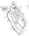
- a locking container 10is illustrated in the drawings More particularly, the locking container 10 includes a pair of cover members 11 and 12 connected to each other through an integral segment 13 defining a living hinge. Each cover member 11 and 12 has a cavity 16 and 17, respectively, therein.
- the cavity 16includes a bottom wall 18 surrounded by an upstanding sidewall 19. The corners of the upstanding sidewall 19 are rounded and the over all shape of the cavity 16 is somewhat rectangular.
- the cavity 17 in the cover member 12is generally identical to the cavity 16. More specifically, the cavity 17 has a bottom wall 21 and an upstanding sidewall 22 surrounding the bottom wall 21. The corners of the sidewall 22 are also rounded and the upper edge 23 conforms to the upper edge 24 of the sidewall 19.
- the edge 23has an outwardly facing step defining a generally horizontal surface 26 and a contiguous vertically upstanding surface 27 terminating in an upper rim 28 adjacent the internal surface of the upstanding sidewall 22.
- the edge 24 on the cover member 11has an internally facing step defined by a horizontally extending surface 31 and a contiguous upstanding vertical surface 32 terminating in a rim 33 adjacent the exterior surface 34 of the cover member 11.
- the cover member 11includes a clasp 36 and the cover member 12 includes a conforming clasp 37 which, when the cover members 11 and 12 are in the closed position, operatively engage one another at their respective inclined surfaces 38 and 39 so as to temporarily hold the cover members 11 and 12 in the closed position.
- the cavity 17 in the cover member 12includes a plurality of upstanding, thin wall, supports 41, 42 and 43 at the juncture between the bottom wall 21 and the segment of the upstanding wall 22 adjacent the living hinge 13.
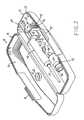
- Each support 41, 42 and 43includes an arcuate depression 44, 45 and 46 in the upper edge thereof, the radius of such arc being such as to conform with the exterior of a syringe barrel 47 of a syringe assembly 48 illustrated in Figure 2.
- the syringe assembly 48includes the aforesaid barrel 47, a plunger 49 movable into the interior of the barrel 47 and a needle encased in a shroud 51 at the end of the barrel 47 remote from the plunger.
- the syringe assembly 48is of a conventional construction and no further discussion concerning it will be presented herein.
- a further thin wall support 52is upstanding from the bottom wall 21 at the juncture between the bottom wall 21 and the portion of the sidewall 22 containing the clasp 37.
- the support 52like the supports 41, 42 and 43 has an arcuate depression 53 in the upper edge thereof.
- an ampouleis adapted to be received in the cavity 17 with a reduced diameter neck 56 thereof being received in the arcuate depression 53.
- each of the upstanding supports 41, 42, 43 and 52are spaced inwardly from the upstanding sidewall 22.
- the cavity 17further includes an upstanding hollow sleeve 56 having a through opening 57 extending centrally therethrough.
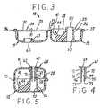
- the hollow sleeve 56is somewhat frustoconical in shape, the larger diameter end being contiguous with the bottom wall 21 of the cover member 12 and the smaller diameter end terminating at an elevation slightly higher than the rim 28 as illustrated in Figures 3 and 5.
- the through opening 57has, adjacent the end thereof remote from the bottom wall 21 a radially inwardly extending bead 58 defining a latch.
- the bottom wall 18 of the cover member 11has an upstanding hollow sleeve 61 provided thereon, which hollow sleeve has a through opening 62 extending centrally therethrough.
- the upper end of the hollow sleeve 61terminates well below the rim 33 when the cover members 11 and 12 are in the closed position as illustrated in Figures 3 and 5, the through opening 62 becoming coaxially oriented with respect to the through opening 57.
- a separationexists between the distal ends of the hollow sleeves 56 and 61 as illustrated in Figure 5.
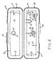
- the bottom wall 21 of the cavity 17includes an upstanding support 63.
- the upstanding support 63includes a pair of parallel sidewalls 64 and 65 and an interconnecting wall 66 joined to the sidewalls 64 and 65 at about the mid-length thereof so as to define an H-shape.
- a plurality of ribs 67project outwardly from opposite facing sides of the interconnecting wall 66 as illustrated in Figure 6.
- a locking key( Figures 1 and 4) is provided and includes an enlarged head 69 and a pair of parallel depending legs 71 and 72 each terminating at a respective distal end 73 and 74 in respective shoulders 75 and 76 which each define a catch adapted to operatively engage the latch bead 58 at the distal end of the hollow sleeve 56.
- the legs 71 and 72have opposing flat surfaces 77 and 78.
- the opposing flat surfaces 77 and 78are adapted to slidingly engage the distal end of the ribs 67 provided on the interconnecting wall 66 extending between the sidewalls 64 and 65 of the support 63 in order to support the locking key on the support 63 as illustrated in Figure 2.
- the locking key 68is prevented from moving sideways by the sidewalls 64 and 65. The only way that the key 68 can be removed from the support 63 is by moving the key 68 relative to the support 63 along the direction of the arrow A.
- the enlarged head 69 of the locking key 68is in the shape of a pad lock to symbolize to the user that the locking key 68 is to perform the locking task. More specifically, and referring to Figure 5, when the cover members 11 and 12 are in the closed position and the through openings 57 and 62 are axially aligned, the locking key 68 is oriented so that the legs 71 and 72 extend first through the through opening 62 and thence past the latch bead 58 in the through opening 57 until the shoulders 75 and 76 become oriented beneath the latch bead 58.
- the locking key 68 and particularly the leg 72 thereofare elastically yieldable to facilitate a movement of the shoulders 75 and 76 past the locking bead 58 and become securely positioned beneath the locking bead at the time that the enlarged head 69 comes into engagement with the exterior surface 34 of the cover member 11.
- the locking containeris now locked.
- the engaged clasps 36 and 37will be released so as to facilitate a movement of the cover member 11 relative to the cover member 12 to the open position illustrated in Figure 2.
- the syringe assembly 48 and the ampoule 54can be removed from the cavity 17. Following a usage of the syringe, it will be desired to dispose of the syringe in a safe manner.
- the used syringe assembly 48is replaced into the cavity 17 on the supports 41, 42 and 43 and, if desired, the ampoule replaced on to the support 52.
- the locking key 68can be moved upwardly away from the support 63 in direction of the arrow A and to a position illustrated in Figure 1. Thereafter, the cover members 11 and 12 can be moved to the closed position illustrated in Figure 5 so that the locking key 68 can be inserted into the now axially aligned through openings 57 and 62 to cause the shoulders 75 and 76 to become oriented beneath the latch bead 58 as described above.
- the wall thickness of the cover members 11 and 12is sufficiently thick so as to prevent an exposed needle from inadvertently becoming stuck through the sidewall of the material of the cover members.
Landscapes
- Health & Medical Sciences (AREA)
- Engineering & Computer Science (AREA)
- Mechanical Engineering (AREA)
- Diabetes (AREA)
- Hematology (AREA)
- Anesthesiology (AREA)
- Biomedical Technology (AREA)
- Heart & Thoracic Surgery (AREA)
- Vascular Medicine (AREA)
- Life Sciences & Earth Sciences (AREA)
- Animal Behavior & Ethology (AREA)
- General Health & Medical Sciences (AREA)
- Public Health (AREA)
- Veterinary Medicine (AREA)
- Infusion, Injection, And Reservoir Apparatuses (AREA)
- Accommodation For Nursing Or Treatment Tables (AREA)
- Closures For Containers (AREA)
Description
Claims (7)
- A locking container for a syringe, comprising:characterised by:a pair of cover members (11,12) that are relativelymovable between opened and closed conditions by means of anintegral hinge (13); andsyringe-holding means (41,42,43) on the inside of oneof the cover members;an elongate locking key comprising a catch (75,76) atone end and an enlarged head (69) at the other end;a pair of holes (57,62), one in each of the covermembers, that are axially-aligned when the cover membersare in the closed condition, and that are adapted tomovably receive the key catch therein; andlatch means (58) fixed in the hole (57) in one covermember (12), for operative engagement with the catch whenthe enlarged head contacts the outer surface of the othercover member (11) in a region adjacent to the hole (62) inthat other cover member, whereupon the key is rendered non-movablein the holes and the cover members are lockedtogether in the closed condition;the hole including the latch means is defined by a hollowsleeve (56) integrally formed in said one cover member andthe latch means is defined by an internal projectinginto the hole and adjacent end of the sleeve.
- A container according to claim 1, which additionalcomprises, on the inside of one of the cover members, means(63) for holding the key.
- A container according to claim 2, wherein the key-holdingmeans includes an upstanding post (63) and the keyincludes means (77,78) for operatively engaging the post.
- A container according to claim 3, wherein the post hasa pair of parallel sidewalls (64,65) interconnected by anintermediate wall (66) extending between the sidewalls,orthogonally thereto, and the key includes a pair of spacedapart and elastically yieldable legs (71,72) appended to acommon side of the enlarged head, such that the legsstraddle the intermediate wall when the key is held by thekey-holding means.
- A container according to any preceding claim, whichadditionally comprises, on the inside of one of the covermembers, a vial holder (52,53).
- A container according to any of claims 2 to 4 andclaim 5, wherein the syringe-holding means, the key-holdingmeans and the vial holder are provided on the same covermember.
- A container according to any preceding claim, whereinthe cover members include releasably engageable claspmembers (36,37).
Applications Claiming Priority (3)
| Application Number | Priority Date | Filing Date | Title |
|---|---|---|---|
| US390964 | 1995-02-21 | ||
| US08/390,964US5566828A (en) | 1995-02-21 | 1995-02-21 | Locking package for a syringe |
| PCT/US1996/001109WO1996025966A1 (en) | 1995-02-21 | 1996-02-08 | Locking package for a syringe |
Publications (2)
| Publication Number | Publication Date |
|---|---|
| EP0812218A1 EP0812218A1 (en) | 1997-12-17 |
| EP0812218B1true EP0812218B1 (en) | 2003-07-30 |
Family
ID=23544662
Family Applications (1)
| Application Number | Title | Priority Date | Filing Date |
|---|---|---|---|
| EP96905242AExpired - LifetimeEP0812218B1 (en) | 1995-02-21 | 1996-02-08 | Locking package for a syringe |
Country Status (14)
| Country | Link |
|---|---|
| US (1) | US5566828A (en) |
| EP (1) | EP0812218B1 (en) |
| JP (1) | JP3635094B2 (en) |
| AR (1) | AR000673A1 (en) |
| AT (1) | ATE246014T1 (en) |
| CA (1) | CA2211720C (en) |
| DE (1) | DE69629281T2 (en) |
| DK (1) | DK0812218T3 (en) |
| ES (1) | ES2203681T3 (en) |
| IL (1) | IL117038A (en) |
| NZ (1) | NZ302888A (en) |
| PT (1) | PT812218E (en) |
| WO (1) | WO1996025966A1 (en) |
| ZA (1) | ZA961027B (en) |
Families Citing this family (62)
| Publication number | Priority date | Publication date | Assignee | Title |
|---|---|---|---|---|
| US6059102A (en)* | 1996-02-05 | 2000-05-09 | Paul J. Gelardi | CD holder |
| US5636737A (en)* | 1996-07-26 | 1997-06-10 | Alpha Enterprises, Inc. | Video cassette shipping container |
| US5975298A (en) | 1997-01-02 | 1999-11-02 | Alpha Enterprises, Inc. | Video cassette container |
| BR9700930A (en)* | 1997-02-07 | 1998-12-08 | Rhone Poulenc Rorer Gmbh | Unit for sale intended for parenteral application a device for the execution of parenteral application as well as a refill unit for the above mentioned unit for sale |
| US5901589A (en)* | 1997-12-11 | 1999-05-11 | Cordero; Carlos T. | Quick opening hand gun safe |
| USD427425S (en)* | 1998-08-20 | 2000-07-04 | Pascal Medical Ab | Casing for a transportable medical instrument |
| US20040069667A1 (en)* | 2000-05-12 | 2004-04-15 | Tomellini Dalita R. | Cases for medication delivery devices |
| US6595362B2 (en) | 2000-05-12 | 2003-07-22 | Lindon Products Inc. | Cases for medication delivery devices |
| US6596299B1 (en)* | 2000-05-19 | 2003-07-22 | Northern Research Laboratories, Inc. | Method of treating periodontal disease |
| JP3565162B2 (en)* | 2000-06-19 | 2004-09-15 | 株式会社日新 | Anti-theft device |
| USD479645S1 (en) | 2000-08-15 | 2003-09-16 | Scimed Life Systems, Inc. | Medical instrument container |
| US6533116B1 (en)* | 2000-08-15 | 2003-03-18 | Scimed Life Systems, Inc. | Medical instrument container |
| AU2001285239A1 (en) | 2000-09-19 | 2002-04-02 | Kendell Simm | Hypodermic needle holder |
| DE20120741U1 (en)* | 2001-01-19 | 2002-04-25 | Wera Werk Hermann Werner GmbH & Co. KG, 42349 Wuppertal | Storage device for one or more tools |
| JP2004533976A (en)* | 2001-07-06 | 2004-11-11 | ウェストバコ・パッケージング・グループ・インク | Media disc package with security lock for retail |
| FR2828089B1 (en) | 2001-08-06 | 2004-05-28 | Benex Ltd | SECURE TRANSPORT CASE FOR MEDICAL EQUIPMENT AND SAMPLES |
| US7077374B1 (en)* | 2001-09-28 | 2006-07-18 | Thomas Joseph Johnson | Mounting apparatus |
| US7635348B2 (en)* | 2003-11-04 | 2009-12-22 | Meridian Medical Technologies, Inc. | Container for medicament automatic injector and automatic injector adapted therefor |
| US7257972B2 (en)* | 2004-08-20 | 2007-08-21 | Bright Aaron L | Locking case for a toothbrush |
| US20060037369A1 (en)* | 2004-08-20 | 2006-02-23 | Bright Aaron L | Locking case for a toothbrush |
| US7624861B2 (en)* | 2004-10-14 | 2009-12-01 | Autotronic Plastics, Inc. | Benefit denial system for securing an asset within a container and method of use |
| US9721064B2 (en) | 2004-11-09 | 2017-08-01 | Startbox, Llc | System and method for preventing wrong-site surgeries |
| CA2629267C (en)* | 2004-11-09 | 2016-10-11 | Startbox, Llc | System and method for preventing wrong-site surgeries |
| US9168107B2 (en) | 2004-11-09 | 2015-10-27 | Startbox, Llc | System and method for preventing wrong-site surgeries |
| DE602006021609D1 (en) | 2005-12-02 | 2011-06-09 | Meadwestvaco Corp | MEDIA STORAGE CONTAINER |
| US8042690B2 (en)* | 2006-04-07 | 2011-10-25 | Portage Plastics Corporation | Wiper blade package |
| US9205075B2 (en) | 2006-07-12 | 2015-12-08 | Mobius Therapeutics, Llc | Apparatus and method for reconstituting a pharmaceutical and preparing the reconstituted pharmaceutical for transient application |
| US9539241B2 (en) | 2006-07-12 | 2017-01-10 | Mobius Therapeutics, Llc | Apparatus and method for reconstituting a pharmaceutical and preparing the reconstituted pharmaceutical for transient application |
| US7806265B2 (en)* | 2006-07-12 | 2010-10-05 | Mobius Therapeutics, Llc | Apparatus and method for reconstituting a pharmaceutical and preparing the reconstituted pharmaceutical for transient application |
| US7607541B2 (en)* | 2006-10-23 | 2009-10-27 | Deborah Girgis | Liquid medication storage and dispensing unit |
| GB0720679D0 (en)* | 2007-10-23 | 2007-12-05 | Meadwestvaco Corp | Closure for a container |
| GB0901806D0 (en)* | 2009-02-04 | 2009-03-11 | Archimedes Dev Ltd | A child resistant container |
| US8177063B1 (en) | 2010-12-29 | 2012-05-15 | Kendell A. Simm | Hypodermic needle holder |
| CN103339034B (en) | 2011-02-04 | 2015-11-25 | 阿基米德开发有限公司 | The container improved |
| CA2877972C (en)* | 2012-07-03 | 2019-04-23 | Biogen Idec Ma Inc. | Device container |
| US20140262884A1 (en)* | 2013-03-14 | 2014-09-18 | Apothecary Products, Inc. | Medicine storage arrangements and methods of assembly and use |
| FR3011824B1 (en)* | 2013-10-15 | 2016-05-13 | Aptar France Sas | DEVICE FOR PACKAGING A FLUID PRODUCT DISPENSER. |
| USD741703S1 (en) | 2014-01-08 | 2015-10-27 | Biogen Ma Inc. | Package |
| WO2015107400A1 (en)* | 2014-01-14 | 2015-07-23 | Bastos Viegas, S.A. | Box for packaging and/or disposal of instruments and its use |
| US9333289B1 (en) | 2015-01-16 | 2016-05-10 | Plas-Tech Engineering, Inc. | Tamper evident closure container |
| JP6746950B2 (en)* | 2015-02-26 | 2020-08-26 | 凸版印刷株式会社 | Container with lid |
| CA2991557C (en)* | 2015-07-10 | 2023-09-26 | Fresenius Kabi Deutschland Gmbh | Syringe packaging system and shell |
| CA2991555A1 (en) | 2015-07-10 | 2017-01-19 | Fresenius Kabi Deutschland Gmbh | Syringe packaging system |
| US10814059B2 (en)* | 2015-07-10 | 2020-10-27 | Fresenius Kabi Deutschland Gmbh | Syringe packaging system |
| US11478320B2 (en)* | 2015-08-06 | 2022-10-25 | Jacobs Emerging Technologies, Llc | Medical device holder |
| US10358255B2 (en)* | 2015-10-13 | 2019-07-23 | Tac Life Systems LLC | Clamshell case for holding medicine and a medicine applicator |
| US9822558B1 (en)* | 2017-02-14 | 2017-11-21 | 3CA Enterprises, Inc. | Tamper evident trailer lock |
| JP7069755B2 (en)* | 2018-01-30 | 2022-05-18 | セイコーエプソン株式会社 | Sheet manufacturing equipment |
| US10722427B2 (en)* | 2018-03-29 | 2020-07-28 | Simon Charles Cantor | Hermetically sealable case for medical device and medicine |
| CN109132080A (en)* | 2018-07-23 | 2019-01-04 | 张天然 | Non-returnable container lock and express box |
| CN109229771A (en)* | 2018-09-18 | 2019-01-18 | 郑州云海信息技术有限公司 | A kind of memory bar shock-proof packaging box |
| GB2577291B (en)* | 2018-09-20 | 2022-11-09 | Simon Aylett Moore Kenneth | Masking package |
| US11351299B2 (en)* | 2019-03-15 | 2022-06-07 | Chiesi Farmaceutici S.P.A. | System comprising a pre-fillable syringe and a package for the pre-fillable syringe |
| US11369733B2 (en)* | 2019-03-15 | 2022-06-28 | Chiesi Farmaceutici S.P.A. | System comprising a pre-fillable syringe and a package for the pre-fillable syringe |
| USD951778S1 (en) | 2019-11-07 | 2022-05-17 | Abbvie Inc. | Sleeve container |
| US11897672B2 (en) | 2019-11-07 | 2024-02-13 | Abbvie Inc. | Sleeve containers for packaging medicinal products |
| USD954563S1 (en) | 2019-11-07 | 2022-06-14 | Abbvie Inc. | Sleeve container |
| US12226587B2 (en)* | 2020-03-23 | 2025-02-18 | Convatec, Inc. | Pre-lubricated female urinary catheter package |
| US11284960B2 (en)* | 2020-05-20 | 2022-03-29 | M_Microtechnologies, Inc. | Packaging container for a medical device |
| DE102020207588A1 (en) | 2020-06-18 | 2021-12-23 | Vetter Pharma-Fertigung GmbH & Co. KG | Shell for holding a plurality of medical hollow bodies |
| WO2021260008A1 (en)* | 2020-06-25 | 2021-12-30 | Sanofi | Drug delivery device recognition |
| EP4257509B1 (en)* | 2020-12-09 | 2024-12-04 | TERUMO Kabushiki Kaisha | Packaging container for medical instrument and packaged medical instrument |
Family Cites Families (18)
| Publication number | Priority date | Publication date | Assignee | Title |
|---|---|---|---|---|
| US3149717A (en)* | 1962-08-27 | 1964-09-22 | Johnson & Johnson | Container for hypodermic needle |
| US3499458A (en)* | 1966-04-01 | 1970-03-10 | Johnson Service Co | Fluid jet modulating control |
| US3439796A (en)* | 1968-02-27 | 1969-04-22 | Intra Products Inc | Tamperproof containers |
| US3489268A (en)* | 1968-05-29 | 1970-01-13 | American Home Prod | Pilferproof package |
| US3727749A (en)* | 1971-07-01 | 1973-04-17 | Graber Rogg Inc | Tamper-proof container |
| US4425999A (en)* | 1982-09-24 | 1984-01-17 | Macdonald Christopher N | Security seal apparatus |
| DE8416122U1 (en)* | 1984-05-26 | 1985-09-26 | Eichner Organisation Kg, 8630 Coburg | Containers for data carriers, in particular for floppy disks |
| GB8823834D0 (en)* | 1988-10-11 | 1988-11-16 | Drg Uk Ltd | Closure for container |
| US4921096A (en)* | 1989-01-17 | 1990-05-01 | Taut, Inc. | Package assembly |
| US4979616A (en)* | 1989-02-23 | 1990-12-25 | Clanton Dennis L | Syringe disposal container |
| US5024326A (en)* | 1989-05-24 | 1991-06-18 | Devon Industries, Inc. | Medical instrument holder and sharps disposal container |
| US5024323A (en)* | 1989-09-25 | 1991-06-18 | Bernard Bolton | Suture extender and needle guard |
| US4969554A (en)* | 1990-02-05 | 1990-11-13 | Sawaya Frederick J | Disposable sharp instrument container |
| US5133454A (en)* | 1990-12-06 | 1992-07-28 | Hammer Steven G | Intravenous catheter biohazard prevention packaging device |
| US5293993A (en)* | 1991-06-14 | 1994-03-15 | Dynamic Bio-Apparatuses, Inc. | Syringe sealing container |
| US5156267A (en)* | 1991-06-14 | 1992-10-20 | Dynamic Bio-Apparatuses, Inc. | Syringe inhibiting container |
| AU6495494A (en)* | 1993-04-12 | 1994-11-08 | Specialized Health Products, Inc. | Container for transport and disposal of medical instruments |
| NL9302132A (en)* | 1993-12-07 | 1995-07-03 | Wiva Bv | Barrel with lockable lid. |
- 1995
- 1995-02-21USUS08/390,964patent/US5566828A/ennot_activeExpired - Lifetime
- 1996
- 1996-02-05ILIL11703896Apatent/IL117038A/ennot_activeIP Right Cessation
- 1996-02-08CACA 2211720patent/CA2211720C/ennot_activeExpired - Fee Related
- 1996-02-08ZAZA9601027Apatent/ZA961027B/enunknown
- 1996-02-08ATAT96905242Tpatent/ATE246014T1/ennot_activeIP Right Cessation
- 1996-02-08NZNZ302888Apatent/NZ302888A/enunknown
- 1996-02-08JPJP52569396Apatent/JP3635094B2/ennot_activeExpired - Fee Related
- 1996-02-08DEDE1996629281patent/DE69629281T2/ennot_activeExpired - Fee Related
- 1996-02-08ESES96905242Tpatent/ES2203681T3/ennot_activeExpired - Lifetime
- 1996-02-08WOPCT/US1996/001109patent/WO1996025966A1/enactiveIP Right Grant
- 1996-02-08EPEP96905242Apatent/EP0812218B1/ennot_activeExpired - Lifetime
- 1996-02-08PTPT96905242Tpatent/PT812218E/enunknown
- 1996-02-08DKDK96905242Tpatent/DK0812218T3/enactive
- 1996-02-19ARAR33545396Apatent/AR000673A1/enunknown
Also Published As
| Publication number | Publication date |
|---|---|
| CA2211720C (en) | 2008-01-15 |
| EP0812218A1 (en) | 1997-12-17 |
| DE69629281D1 (en) | 2003-09-04 |
| ATE246014T1 (en) | 2003-08-15 |
| AR000673A1 (en) | 1997-07-10 |
| ES2203681T3 (en) | 2004-04-16 |
| MX9706326A (en) | 1997-11-29 |
| DK0812218T3 (en) | 2003-11-03 |
| US5566828A (en) | 1996-10-22 |
| AU686932B2 (en) | 1998-02-12 |
| JP3635094B2 (en) | 2005-03-30 |
| DE69629281T2 (en) | 2004-05-27 |
| PT812218E (en) | 2003-12-31 |
| IL117038A0 (en) | 1996-06-18 |
| IL117038A (en) | 2000-07-16 |
| WO1996025966A1 (en) | 1996-08-29 |
| AU4905296A (en) | 1996-09-11 |
| CA2211720A1 (en) | 1996-08-29 |
| JPH11500043A (en) | 1999-01-06 |
| ZA961027B (en) | 1997-08-08 |
| NZ302888A (en) | 1998-05-27 |
Similar Documents
| Publication | Publication Date | Title |
|---|---|---|
| EP0812218B1 (en) | Locking package for a syringe | |
| US5797885A (en) | Apparatus and method for recapping syringe needles | |
| US4484916A (en) | Medical solution container and port construction | |
| US4850976A (en) | Combination sheath and foldable shield for hypodermic syringe needle | |
| US4979616A (en) | Syringe disposal container | |
| US5259840A (en) | Locking syringe | |
| US5067948A (en) | Safety, packaging, injection and disposal system for pre-filled pharmaceutical vials | |
| US4351434A (en) | Disposal of needles | |
| US5304138A (en) | Single use, destructible medical syringe | |
| US4629453A (en) | Hypodermic needle protection device | |
| US4592092A (en) | Medical solution container and port construction therefor | |
| US4875265A (en) | Injection needle-detaching device | |
| US5605544A (en) | Safety injector with returnable needle | |
| JPS6045361A (en) | Disposal apparatus of subcateneous syringe needle | |
| EP0824895B1 (en) | Infectious waste container for blood collection needles | |
| JPH08294533A (en) | Safety device for injector | |
| JPH0337408B2 (en) | ||
| AU686932C (en) | Locking package for a syringe | |
| JP3044544U (en) | Syringe | |
| JPH0350915Y2 (en) | ||
| KR20190142117A (en) | One-touch vertical safety cap syringe to prevent stab injury and reuse | |
| JPH0754162Y2 (en) | Medical waste container | |
| JPS5835258Y2 (en) | Structure of the hanging part of the infusion bottle | |
| WO1990006784A1 (en) | Hypodermic syringe carriers | |
| JPH0445709Y2 (en) |
Legal Events
| Date | Code | Title | Description |
|---|---|---|---|
| PUAI | Public reference made under article 153(3) epc to a published international application that has entered the european phase | Free format text:ORIGINAL CODE: 0009012 | |
| 17P | Request for examination filed | Effective date:19970911 | |
| AK | Designated contracting states | Kind code of ref document:A1 Designated state(s):AT BE CH DE DK ES FR GB GR IE IT LI LU MC NL PT SE | |
| AX | Request for extension of the european patent | Free format text:AL PAYMENT 970911;LT PAYMENT 970911;LV PAYMENT 970911;SI PAYMENT 970911 | |
| 17Q | First examination report despatched | Effective date:20020204 | |
| GRAH | Despatch of communication of intention to grant a patent | Free format text:ORIGINAL CODE: EPIDOS IGRA | |
| GRAH | Despatch of communication of intention to grant a patent | Free format text:ORIGINAL CODE: EPIDOS IGRA | |
| GRAA | (expected) grant | Free format text:ORIGINAL CODE: 0009210 | |
| AK | Designated contracting states | Designated state(s):AT BE CH DE DK ES FR GB GR IE IT LI LU MC NL PT SE | |
| AX | Request for extension of the european patent | Extension state:AL LT LV SI | |
| REG | Reference to a national code | Ref country code:GB Ref legal event code:FG4D | |
| REG | Reference to a national code | Ref country code:CH Ref legal event code:EP | |
| REG | Reference to a national code | Ref country code:IE Ref legal event code:FG4D | |
| REF | Corresponds to: | Ref document number:69629281 Country of ref document:DE Date of ref document:20030904 Kind code of ref document:P | |
| REG | Reference to a national code | Ref country code:SE Ref legal event code:TRGR | |
| REG | Reference to a national code | Ref country code:DK Ref legal event code:T3 | |
| REG | Reference to a national code | Ref country code:GR Ref legal event code:EP Ref document number:20030403953 Country of ref document:GR | |
| REG | Reference to a national code | Ref country code:CH Ref legal event code:NV Representative=s name:DR. SCHNEIDER & PARTNER INTELLECTUAL PROPERTY RIGH | |
| LTIE | Lt: invalidation of european patent or patent extension | Effective date:20030730 | |
| REG | Reference to a national code | Ref country code:ES Ref legal event code:FG2A Ref document number:2203681 Country of ref document:ES Kind code of ref document:T3 | |
| ET | Fr: translation filed | ||
| PLBE | No opposition filed within time limit | Free format text:ORIGINAL CODE: 0009261 | |
| STAA | Information on the status of an ep patent application or granted ep patent | Free format text:STATUS: NO OPPOSITION FILED WITHIN TIME LIMIT | |
| 26N | No opposition filed | Effective date:20040504 | |
| REG | Reference to a national code | Ref country code:CH Ref legal event code:PFA Owner name:PHARMACIA & UPJOHN COMPANY Free format text:PHARMACIA & UPJOHN COMPANY#301 HENRIETTA STREET#KALAMAZOO, MICHIGAN 49001 (US) -TRANSFER TO- PHARMACIA & UPJOHN COMPANY#301 HENRIETTA STREET#KALAMAZOO, MICHIGAN 49001 (US) | |
| PGFP | Annual fee paid to national office [announced via postgrant information from national office to epo] | Ref country code:LU Payment date:20071228 Year of fee payment:13 | |
| PGFP | Annual fee paid to national office [announced via postgrant information from national office to epo] | Ref country code:ES Payment date:20080221 Year of fee payment:13 Ref country code:DK Payment date:20080111 Year of fee payment:13 Ref country code:CH Payment date:20080108 Year of fee payment:13 | |
| PGFP | Annual fee paid to national office [announced via postgrant information from national office to epo] | Ref country code:SE Payment date:20080208 Year of fee payment:13 Ref country code:PT Payment date:20080103 Year of fee payment:13 Ref country code:NL Payment date:20080111 Year of fee payment:13 Ref country code:MC Payment date:20080109 Year of fee payment:13 Ref country code:IT Payment date:20080221 Year of fee payment:13 Ref country code:DE Payment date:20080229 Year of fee payment:13 Ref country code:IE Payment date:20080123 Year of fee payment:13 Ref country code:GB Payment date:20080108 Year of fee payment:13 | |
| PGFP | Annual fee paid to national office [announced via postgrant information from national office to epo] | Ref country code:AT Payment date:20080109 Year of fee payment:13 | |
| PGFP | Annual fee paid to national office [announced via postgrant information from national office to epo] | Ref country code:FR Payment date:20080212 Year of fee payment:13 | |
| PGFP | Annual fee paid to national office [announced via postgrant information from national office to epo] | Ref country code:BE Payment date:20080228 Year of fee payment:13 | |
| PGFP | Annual fee paid to national office [announced via postgrant information from national office to epo] | Ref country code:GR Payment date:20080116 Year of fee payment:13 | |
| REG | Reference to a national code | Ref country code:PT Ref legal event code:MM4A Free format text:LAPSE DUE TO NON-PAYMENT OF FEES Effective date:20090810 | |
| BERE | Be: lapsed | Owner name:*PHARMACIA & UPJOHN CY Effective date:20090228 | |
| PG25 | Lapsed in a contracting state [announced via postgrant information from national office to epo] | Ref country code:MC Free format text:LAPSE BECAUSE OF NON-PAYMENT OF DUE FEES Effective date:20090228 | |
| REG | Reference to a national code | Ref country code:CH Ref legal event code:PL | |
| EUG | Se: european patent has lapsed | ||
| REG | Reference to a national code | Ref country code:DK Ref legal event code:EBP | |
| GBPC | Gb: european patent ceased through non-payment of renewal fee | Effective date:20090208 | |
| PG25 | Lapsed in a contracting state [announced via postgrant information from national office to epo] | Ref country code:PT Free format text:LAPSE BECAUSE OF NON-PAYMENT OF DUE FEES Effective date:20090810 Ref country code:LI Free format text:LAPSE BECAUSE OF NON-PAYMENT OF DUE FEES Effective date:20090228 Ref country code:CH Free format text:LAPSE BECAUSE OF NON-PAYMENT OF DUE FEES Effective date:20090228 Ref country code:AT Free format text:LAPSE BECAUSE OF NON-PAYMENT OF DUE FEES Effective date:20090208 | |
| NLV4 | Nl: lapsed or anulled due to non-payment of the annual fee | Effective date:20090901 | |
| REG | Reference to a national code | Ref country code:IE Ref legal event code:MM4A | |
| REG | Reference to a national code | Ref country code:FR Ref legal event code:ST Effective date:20091030 | |
| PG25 | Lapsed in a contracting state [announced via postgrant information from national office to epo] | Ref country code:NL Free format text:LAPSE BECAUSE OF NON-PAYMENT OF DUE FEES Effective date:20090901 | |
| PG25 | Lapsed in a contracting state [announced via postgrant information from national office to epo] | Ref country code:IE Free format text:LAPSE BECAUSE OF NON-PAYMENT OF DUE FEES Effective date:20090209 Ref country code:DE Free format text:LAPSE BECAUSE OF NON-PAYMENT OF DUE FEES Effective date:20090901 | |
| PG25 | Lapsed in a contracting state [announced via postgrant information from national office to epo] | Ref country code:BE Free format text:LAPSE BECAUSE OF NON-PAYMENT OF DUE FEES Effective date:20090228 Ref country code:GR Free format text:LAPSE BECAUSE OF NON-PAYMENT OF DUE FEES Effective date:20090902 | |
| REG | Reference to a national code | Ref country code:ES Ref legal event code:FD2A Effective date:20090209 | |
| PG25 | Lapsed in a contracting state [announced via postgrant information from national office to epo] | Ref country code:GB Free format text:LAPSE BECAUSE OF NON-PAYMENT OF DUE FEES Effective date:20090208 Ref country code:FR Free format text:LAPSE BECAUSE OF NON-PAYMENT OF DUE FEES Effective date:20090302 | |
| PG25 | Lapsed in a contracting state [announced via postgrant information from national office to epo] | Ref country code:ES Free format text:LAPSE BECAUSE OF NON-PAYMENT OF DUE FEES Effective date:20090209 Ref country code:DK Free format text:LAPSE BECAUSE OF NON-PAYMENT OF DUE FEES Effective date:20090831 | |
| PG25 | Lapsed in a contracting state [announced via postgrant information from national office to epo] | Ref country code:IT Free format text:LAPSE BECAUSE OF NON-PAYMENT OF DUE FEES Effective date:20090208 | |
| PG25 | Lapsed in a contracting state [announced via postgrant information from national office to epo] | Ref country code:LU Free format text:LAPSE BECAUSE OF NON-PAYMENT OF DUE FEES Effective date:20090208 | |
| PG25 | Lapsed in a contracting state [announced via postgrant information from national office to epo] | Ref country code:SE Free format text:LAPSE BECAUSE OF NON-PAYMENT OF DUE FEES Effective date:20090209 |