EP0810742B1 - Direct sequence code division multiple access transmission method using pilot symbols - Google Patents
Direct sequence code division multiple access transmission method using pilot symbolsDownload PDFInfo
- Publication number
- EP0810742B1 EP0810742B1EP97303705AEP97303705AEP0810742B1EP 0810742 B1EP0810742 B1EP 0810742B1EP 97303705 AEP97303705 AEP 97303705AEP 97303705 AEP97303705 AEP 97303705AEP 0810742 B1EP0810742 B1EP 0810742B1
- Authority
- EP
- European Patent Office
- Prior art keywords
- code
- spreading
- pilot symbols
- symbols
- channel
- Prior art date
- Legal status (The legal status is an assumption and is not a legal conclusion. Google has not performed a legal analysis and makes no representation as to the accuracy of the status listed.)
- Revoked
Links
- 230000005540biological transmissionEffects0.000titleclaimsdescription68
- 238000000034methodMethods0.000titleclaimsdescription35
- 230000007480spreadingEffects0.000claimsdescription63
- 238000001514detection methodMethods0.000claimsdescription10
- 230000001427coherent effectEffects0.000claimsdescription9
- 238000010586diagramMethods0.000description30
- 238000005562fadingMethods0.000description12
- 238000003780insertionMethods0.000description8
- 230000037431insertionEffects0.000description8
- 108010003272Hyaluronate lyaseProteins0.000description3
- 238000010295mobile communicationMethods0.000description3
- 238000012545processingMethods0.000description3
- 238000006243chemical reactionMethods0.000description2
- 230000008054signal transmissionEffects0.000description2
- 238000012546transferMethods0.000description2
- 238000012935AveragingMethods0.000description1
- 230000015556catabolic processEffects0.000description1
- 238000004891communicationMethods0.000description1
- 230000007423decreaseEffects0.000description1
- 238000006731degradation reactionMethods0.000description1
- 238000009826distributionMethods0.000description1
- 230000000694effectsEffects0.000description1
- 239000000284extractSubstances0.000description1
- 230000008569processEffects0.000description1
- 238000012827research and developmentMethods0.000description1
- 230000004044responseEffects0.000description1
- 238000001228spectrumMethods0.000description1
- 238000009827uniform distributionMethods0.000description1
Images


Classifications
- H—ELECTRICITY
- H04—ELECTRIC COMMUNICATION TECHNIQUE
- H04J—MULTIPLEX COMMUNICATION
- H04J13/00—Code division multiplex systems
- H04J13/16—Code allocation
- H04J13/18—Allocation of orthogonal codes
- H—ELECTRICITY
- H04—ELECTRIC COMMUNICATION TECHNIQUE
- H04J—MULTIPLEX COMMUNICATION
- H04J13/00—Code division multiplex systems
- H—ELECTRICITY
- H04—ELECTRIC COMMUNICATION TECHNIQUE
- H04B—TRANSMISSION
- H04B7/00—Radio transmission systems, i.e. using radiation field
- H04B7/24—Radio transmission systems, i.e. using radiation field for communication between two or more posts
- H04B7/26—Radio transmission systems, i.e. using radiation field for communication between two or more posts at least one of which is mobile
- H04B7/2628—Radio transmission systems, i.e. using radiation field for communication between two or more posts at least one of which is mobile using code-division multiple access [CDMA] or spread spectrum multiple access [SSMA]
- H04B7/2637—Radio transmission systems, i.e. using radiation field for communication between two or more posts at least one of which is mobile using code-division multiple access [CDMA] or spread spectrum multiple access [SSMA] for logical channel control
- H—ELECTRICITY
- H04—ELECTRIC COMMUNICATION TECHNIQUE
- H04B—TRANSMISSION
- H04B2201/00—Indexing scheme relating to details of transmission systems not covered by a single group of H04B3/00 - H04B13/00
- H04B2201/69—Orthogonal indexing scheme relating to spread spectrum techniques in general
- H04B2201/707—Orthogonal indexing scheme relating to spread spectrum techniques in general relating to direct sequence modulation
- H04B2201/70701—Orthogonal indexing scheme relating to spread spectrum techniques in general relating to direct sequence modulation featuring pilot assisted reception
- H—ELECTRICITY
- H04—ELECTRIC COMMUNICATION TECHNIQUE
- H04J—MULTIPLEX COMMUNICATION
- H04J13/00—Code division multiplex systems
- H04J13/0077—Multicode, e.g. multiple codes assigned to one user
Definitions
- the present inventionrelates to a direct sequence code division multiple access (DS-CDMA) transmission method carrying out multiple access using spread spectrum in mobile communications, and particularly to a DS-CDMA transmission method that carries out code multiplexing of multiple code channels.
- DS-CDMAdirect sequence code division multiple access
- the DS-CDMA transmission systemcarries out communications between multiple users using the same frequency band, and individual users are identified by a spreading code properly assigned to each user.
- the DS-CDMA systemhas advantages over the frequency division multiple access or time division multiple access in that it can increase the capacity in terms of the number of simultaneous subscribers within the same available frequency band, and is suitable for high speed signal transmission because it transmits information signals after spreading them into wideband signals.
- the received signalundergoes Rayleigh fading.
- Rayleigh fadingthe amplitude of a received signal has Rayleigh distribution, and its phase has a uniform distribution. It is necessary for a receiver to estimate the randomly varying phase of the received signal to carry out coherent detection which is more efficient than differential detection.
- One of the methods for estimating the received phaseis implemented by inserting pilot symbols of a known pattern into information symbols at fixed intervals, and by estimating the received phase of each information symbol on the basis of the received phases estimated using the pilot symbols. In this case, the pilot symbols must be inserted at every time interval during which the phase fluctuation due to fading is nearly negligible.
- Fig. 16shows a conventional channel structure when carrying out the absolute coherent detection which makes the channel (amplitude and phase) estimation using the pilot symbols as mentioned above.
- Ndenotes the number of code channels (the number of code multiplexing).
- Each code channelis spread using a short code (SC-1, ..., SC-N) with a period equal to that of information symbol, and is further spread using a spreading code referred to as a long code (LC-Y) with a period much longer than that of the common information symbol.
- the short codesserve to identify the individual code channels
- the long codeserves to distinguish a user from the other simultaneous users in the same cell in reverse link channels, and from the other simultaneous users in the other cells in forward link channels.
- Fig. 17shows a frame structure of a single code channel transmission.
- the conventional systemhas the following problems:
- Another object of the present inventionis to provide a DS-CDMA transmission method which can improve the tracking ability to fading of the channel estimation and the transmission power control using the pilot symbols without much increasing the circuit scale of the transmitter and receiver in the DS-CDMA code multiplexing.
- a DS-CDMA transmission method using a code multiplexing method which transmits a signal by generating a high bit rate transmission channel by code multiplexing a plurality of code channelssaid DS-CDMA transmission method characterized by comprising the steps of:
- a DS-CDMA transmitterfor performing a method according to the first aspect, having:
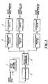
- Fig. 1shows an example of a channel structure of a DS-CDMA transmission system in accordance with the present invention.
- each frame of a code channel with a fundamental transmission rate fbconsists of pilot symbols and information data whose information rate is expanded by spreading factor (processing gain) into a wideband signal.
- the N code multiplexing of such fundamental channelsenables the information to be transmitted at the transmission rate of N ⁇ fb bps, if all the channels have the same quality as the fundamental channel.
- a common spreading codeis used to spread the pilot symbols of the N code channels, the cross-correlation between the individual code channels can be eliminated. Since the code channels undergo the same fading in the multicode multiplex transmission, the same pilot symbols can be used in common.
- Fig. 2illustrates a channel structure different from that of Fig. 1, in which only one code channel transmits the pilot symbols.
- Fig. 3is a block diagram showing an error correcting encoder in the multicode multiplex transmission.
- Input information datais coded by an outer code encoder 1 using an outer code of a concatenated error correcting code, undergoes interleaving by an interleaver 2, and is distributed to N code channels through a serial-to-parallel converter 3.
- convolutional coding by a convolutional encoder 4 and interleaving by an interleaver 5are carried out successively for each code channel.
- Fig. 9Aillustrates an interleaving method of the DS-CDMA transmission system.
- the entire information data in Z-framesare written in the X 1 data direction for each code channel, and are read in the Y 1 data direction perpendicular to the write direction.
- Fig. 4shows a configuration of an error correcting encoder of the transmitter of the DS-CDMA transmission system.
- the input information datais encoded by an outer code encoder 6 using an outer code of a concatenated error correcting code, and undergoes interleaving by an interleaver 7 to be output.
- the output datacollectively undergo a convolutional coding by a convolutional encoder 8, and the convolutionally encoded information sequence is collectively interleaved by an interleaver 9.
- Fig. 10Aillustrates an interleaving method of the present DS-CDMA transmission system.
- the convolutionally encoded information data sequenceis written at every N ⁇ X 2 period, and after thus writing the entire information data in the Z frames, the data are read at every Y 2 information data period in the direction perpendicular to the write direction.
- the interleaved information dataare distributed into N code channels by a serial-to-parallel converter 10.
- Fig. 5is a block diagram showing the transmitter of the DS-CDMA transmission system.
- Each frame assembler 11inserts pilot symbols, which are used for channel estimation for the coherent detection, into the coded information data of each code channel shown in Figs. 3 and 4 at fixed intervals (the pilot symbols may be inserted into only one code channel if it is desired to do so).
- the dataare modulated by each modulator 12.
- the modulated data symbols of each code channel output from each modulator 12are spread using a spreading code (SC-X ⁇ LC-Y) for the pilot symbols, and using spreading codes (SC-P ⁇ LC-Y, where P represents 1-N) for the information symbols of respective code channels.
- the spread signals of respective code channelsare summed up by an adder 14 to be transmitted.
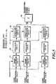
- Fig. 6is a block diagram showing a receiver of the DS-CDMA transmission system.
- the received spread signalis input in common to matched filters 15-0, ..., 15-N corresponding to the spreading codes.
- the pilot symbols in the received signalare despread by the matched filter 15-0 using the spreading code (SC-X ⁇ LC-Y) as the spreading code replica.
- the received phase of the pilot symbolsis estimated by a pilot symbol channel estimator 16 which averages several pilot symbols using the output from a frame synchronizer 17.
- An information symbol channel estimator 18estimates the received phase at each position of the information symbols by interpolating the estimated information fed from the pilot symbol channel estimator 16.
- the estimated phase fluctuations in the information symbolscan be used in common to the entire code channels.
- the information symbols on individual code channelsare despread by the matched filters 15-1 - 15-N using different spreading codes (SC-P ⁇ LC-Y, where P denotes 1-N) as spreading code replicas for respective channels.
- SC-P ⁇ LC-Ydifferent spreading codes
- each channel compensator 19compensates the despread information symbols on the code channels for the received phase fluctuations which are estimated using the pilot symbols.
- the phase estimator and compensator (17, 18 and 19)which use pilot channels corresponding to N code channels as shown in Fig. 6, are used for each multipath to be combined.
- the information symbols from respective paths which have been compensated for the fading phase fluctuations by the channel compensator 19 of each channelare RAKE combined by a RAKE combiner 20 which sums up the multipath components using estimated received complex envelopes of individual paths as weights.
- the RAKE combined signalsare each input to an error correcting decoder as shown in Figs. 7 and 8.
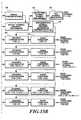
- Fig. 7shows a configuration of the error correcting decoder of the DS-CDMA transmission system.
- the RAKE combined signalsare each deinterleaved by a deinterleaver 21 separately for each code channel.
- Fig. 9Billustrates a deinterleaving method of the DS-CDMA transmission system, in which write and read are carried out in the directions opposite to those in the interleaving method as shown in Fig. 9A.
- the deinterleaved signalsare each decoded by a Viterbi decoder 22 separately for each channel.
- the decoded data of the respective code channelsundergo parallel-to-serial conversion by a parallel-to-serial converter 23, followed by the deinterleave by a deinterleaver 24 and the decoding by an outer code decoder 25, to be output.
- Fig. 8shows another configuration of the error correcting decoder of the DS-CDMA transmission system.
- the RAKE combined signals of the N code channelsundergo parallel-to-serial conversion by a parallel-to-serial converter 26, and then are collectively deinterleaved by a deinterleaver 27.
- Fig. 10Billustrates a deinterleaving method of the DS-CDMA transmission system, in which write and read are carried out in the directions opposite to those in the interleaving method as shown in Fig. 10A.
- the deinterleaved signalsare collectively decoded by a Viterbi decoder 28, followed by the deinterleave by a deinterleaver 29 and decoding by an outer code decoder 30, to be output.
- Fig. 11shows another example of a channel structure of a DS-CDMA transmission system.
- each frame of a code channel with a fundamental transmission rate fbconsists of pilot symbols and information data whose information rate is expanded by the spreading factor (processing gain), thereby generating a wideband signal.
- the N code multiplexing of such fundamental channelsenables the information to be transmitted at the transmission rate of N x fb bps, if all the channels have the same quality as the fundamental channel.
- the integer Kmay be even or odd.
- the H code channels in the same blockhave the pilot symbols inserted at the same positions in the frames.
- the inserted positions of the pilot symbols in the K blocksare shifted such that the intervals become uniform between the closest pilot symbols.
- the input information dataalso undergo the error correcting encoding by the error correcting encoder as shown in Fig. 3.
- the dataare interleaved by the same method as shown in Fig. 9A.
- Fig. 14A and Fig. 14Bare block diagrams showing the transmitter of the DS-CDMA transmission system
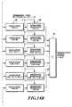
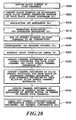
- Fig. 20is a flowchart of the transmission and reception (S200-S250).
- Each frame assembler 31inserts pilot symbols, which are used for channel estimation for the coherent detection, into the coded information data of each code channel fed from the circuit as shown in Fig. 3, at fixed intervals in accordance with a pilot symbol insertion pattern of the block to which the code channel belongs (S200-S210).
- the modulated data symbols of the code channels output from respective modulators 32are separately spread by spreading modulators 33 using spreading codes (SC-P ⁇ LC-Y, where P represents 1-N) assigned to respective code channels (S215).
- the spread signals of the respective code channelsare summed up by an adder 34 to be transmitted (S220).
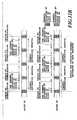
- Fig. 15A and Fig. 15Bare block diagrams showing a receiver of the DS-CDMA transmission system.
- the received spread signalis input in common to matched filters 35 corresponding to the respective spreading codes.
- the pilot symbols and information symbols in the code channelsare despread separately for respective channels by the matched filters 35 using the spreading codes (SC-P ⁇ LC-Y, where P represents 1-N) as the spreading code replicas (S225).
- a demultiplexer (DEMUX) 36 corresponding to each code channelextracts from the information symbols the pilot symbols inserted into different positions in the respective blocks (S230).
- the received phase of the pilot symbolsis estimated by a pilot symbol channel estimator 37 which averages separately for each code channel between several pilot symbols using the output from a frame synchronizer 38 which carries out coherent detection of the pilot symbols in response to the output of the matched filter 35 (S235).
- the estimates of the received phase at the pilot symbol positions in each blockare obtained by averaging the estimates of the received phase of the code channels in that block (S240).
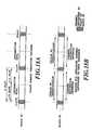
- Fig. 12Ashows a pilot symbol insertion pattern in each block.
- An information symbol channel estimator 39can obtain transfer functions of the channels on the information data sequence by making interpolation at every insertion interval of the entire pilot symbols throughout the entire code channels by using, in common to all the code channels, the estimates of the received phase at the pilot symbol positions of the respective blocks as shown in Fig. 12B (S245). This can improve the tracking ability to fading in the channel estimation because of the reduced interval of the interpolation in the channel estimation.
- each channel compensator 40compensates the information symbols on the code channels fed from the demultiplexers 36 for the received phase fluctuations which are estimated using the pilot symbols (S250).
- a received signal power measurer 41measures the received signal power at the pilot symbol positions of each code channel on the basis of the signal fed from the pilot symbol channel estimator 37. Then, it averages in each block the measured values of the received signal power of the code channels belonging to that block, thereby obtaining the measured values of the received signal power (SIR) at the pilot symbol positions of the block.
- a transmission power control signal generator 42generates a transmission power control (TPC) signal based on the measured values.
- TPCtransmission power control
- the measured values of the received signal power at the pilot symbol positions in respective blocksare used in common to the entire code channels as shown in Fig. 13. This makes it possible to achieve the transmission power control at the insertion intervals of the entire pilot symbols inserted into all the code channels, and hence to improve the fading tracking ability in the transmission power control because of the virtually reduced transmission power control period.
- phase estimator and compensator(37, 38, 39 and 40), which use pilot channels corresponding to N code channels as shown in Fig. 15, are used for each multipath to be combined.
- the information symbols from respective paths which have been compensated for the fading phase fluctuations by each channel compensator 40are RAKE combined by each RAKE combiner 43 which sums up the multipath components using estimated received complex envelopes of individual paths as weights.
- the RAKE combined signalsare each input to an error correcting decoder as shown in Fig. 7.
Landscapes
- Engineering & Computer Science (AREA)
- Computer Networks & Wireless Communication (AREA)
- Signal Processing (AREA)
- Mobile Radio Communication Systems (AREA)
Description
- The present invention relates to a directsequence code division multiple access (DS-CDMA)transmission method carrying out multiple accessusing spread spectrum in mobile communications, andparticularly to a DS-CDMA transmission method thatcarries out code multiplexing of multiple codechannels.
- Recently, intensive research and development ofthe DS-CDMA system have been made as one of the nextgeneration mobile communication systems. The DS-CDMAtransmission system carries out communicationsbetween multiple users using the same frequencyband, and individual users are identified by aspreading code properly assigned to each user.
- The DS-CDMA system has advantages over thefrequency division multiple access or time divisionmultiple access in that it can increase the capacityin terms of the number of simultaneous subscriberswithin the same available frequency band, and issuitable for high speed signal transmission becauseit transmits information signals after spreadingthem into wideband signals.
- In the mobile communication environment,straight paths between a base station and mobile stations are seldom unobstructed, therebyconstituting multipath propagation. As a result,the received signal undergoes Rayleigh fading. InRayleigh fading, the amplitude of a received signalhas Rayleigh distribution, and its phase has auniform distribution. It is necessary for areceiver to estimate the randomly varying phase ofthe received signal to carry out coherent detectionwhich is more efficient than differential detection.One of the methods for estimating the received phaseis implemented by inserting pilot symbols of a knownpattern into information symbols at fixed intervals,and by estimating the received phase of eachinformation symbol on the basis of the receivedphases estimated using the pilot symbols. In thiscase, the pilot symbols must be inserted at everytime interval during which the phase fluctuation dueto fading is nearly negligible.
- There are mainly two methods for implementinghigh bit rate signal transmission in the DS-CDMAsystem: (1) a method which varies a spreadingfactor (processing gain) in accordance with thetransmission information rate; and (2) a codemultiplexing method which multiplexes multiplechannels each having a fundamental information rate.Here, we will consider the second method.
- Fig. 16 shows a conventional channel structurewhen carrying out the absolute coherent detectionwhich makes the channel (amplitude and phase)estimation using the pilot symbols as mentionedabove. In this figure, N denotes the number of codechannels (the number of code multiplexing). Eachcode channel is spread using a short code (SC-1,..., SC-N) with a period equal to that ofinformation symbol, and is further spread using aspreading code referred to as a long code (LC-Y) with a period much longer than that of the commoninformation symbol. The short codes serve toidentify the individual code channels, and the longcode serves to distinguish a user from the othersimultaneous users in the same cell in reverse linkchannels, and from the other simultaneous users inthe other cells in forward link channels. Fig. 17shows a frame structure of a single code channeltransmission.
- Further, as another conventional example, thereis a technique described in W093/15573. This is aninvention related to an access technique combiningTDMA and CDMA. The signal configuration is describedin its Figure 5. A plurality of code channels arespread by special spreading codes (CODE O - CODE X), aplurality of data are time-division-multiplexed ineach code channel, and each of the data contains asynchronization code and ATM cell data (Figure 5a).Since synchronization codes (pilots) of different codechannels are spread by different spreading codes, theprocess of this technique is similar to that of Figure16 described above.
- The conventional system has the followingproblems:
- (1) The pilot symbols, which are inserted intoeach code channel as shown in Fig. 16,or WO93/15573, are spread by the same spreadingcode assigned to each code channel for spreadingdata symbols. This results in some cross-correlationbetween the multiplexed code channels, whichdegrades the accuracy of the channel estimation bythe pilot symbols. In other words, the conventionalDS-CDMA code multiplexing method has a problem inthat the accuracy of the channel estimation usingthe pilot symbols degrades owing to the cross-correlationbetween other code channels because thepilot symbols of respective code channels are spreadusing different spreading codes. The degradation isremarkable when the received signal power per pathdecreases under the multipath environment.
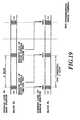
- (2) The pilot symbols, which are inserted atthe same positions in frames in the respective codechannels as shown in Fig. 18A, are used to estimatethe received phases for each code channel so as toobtain the transfer function of the channel oninformation data sequence by means of interpolationat the insertion intervals of the pilot symbols asshown in Fig. 18B. This results in a problem inthat the accuracy of the channel estimation degrades with an increase in the fading fluctuation speed.In addition, since the transmission power control isalso carried out at the insertion intervals of thepilot symbols by measuring the received signal powerat the positions of the pilot symbols which areinserted in the same positions in the frames ofrespective code channels as shown in Fig. 19, thereis another problem in that the accuracy of thetransmission power control also degrades with anincrease in the fading fluctuation speed.
- It is therefore an object of the presentinvention to provide a DS-CDMA transmission methodwhich can improve the accuracy of the channelestimation without much increasing the circuit scaleof a transmitter and receiver in the DS-CDMA codemultiplexing.
- Another object of the present invention is toprovide a DS-CDMA transmission method which canimprove the tracking ability to fading of thechannel estimation and the transmission powercontrol using the pilot symbols without muchincreasing the circuit scale of the transmitter andreceiver in the DS-CDMA code multiplexing.
- According to a first aspect of the presentinvention, there is provided a DS-CDMA transmissionmethod using a code multiplexing method whichtransmits a signal by generating a high bit ratetransmission channel by code multiplexing a pluralityof code channels, said DS-CDMA transmission methodcharacterized by comprising the steps of:
- assembling frames for a plurality of codechannels by inserting pilot symbols into informationsymbols at fixed intervals, said pilot symbols beingused for channel estimation for coherent detection;
- spreading said information symbols in each ofsaid code channels using a spreading code properlyassigned to said each of said code channels, saidspreading code being selected from a group oforthogonal spreading codes that are orthogonal to eachother and have a period equal to an information symbolperiod; and
- spreading said pilot symbols in said codechannels using one of the spreading codes beingselected from said group of said orthogonal spreadingcodes, or any of the spreading codes other than thespreading codes assigned to said information symbolsin said code channels from said group of saidorthogonal spreading codes.
- According to a second aspect of the presentinvention, there is provided a DS-CDMA transmitter,for performing a method according to the first aspect,having:
- frame assembler means to frame informationsymbols and to insert, between information symbols atfixed intervals, pilot symbols patterned for coherentdetection;
- spread modulation means, responsive to suppliedspreading codes and operable on the frame informationsymbols and pilot symbols, and
- spreading code supply means to supply thespreading codes; wherein said spreading code supply means isadapted to supply a respective different orthogonalspreading code for spreading the information symbolsof each respective different channel and to supply acommon spreading code, that is either the same as oneof said different orthogonal spreading codes or isorthogonal to said different orthogonal spreadingcodes, for spreading the pilot symbols of eachchannel, which spreading codes each have a periodequal to that of said information symbols of eachchannel.
- The above and other objects, effects, featuresand advantages of the present invention will becomemore apparent from the following description of theembodiments thereof taken in conjunction with theaccompanying drawings.
- Fig. 1 is a diagram illustrating an example of achannel structure in the DS-CDMA transmission systemin accordance with the present invention;
- Fig. 2 is a diagram illustrating another exampleof a channel structure in the DS-CDMA transmissionsystem in accordance with the present invention;
- Fig. 3 is a block diagram showing aconfiguration of an example of an errorcorrecting encoder in the DS-CDMA transmissionsystem;
- Fig. 4 is a block diagram showing anotherconfiguration of an example of an errorcorrecting encoder in the DS-CDMA transmissionsystem;
- Fig. 5 is a block diagram showing aconfiguration of an embodiment of a transmitter inthe DS-CDMA transmission system in accordance withthe present invention;
- Fig. 6 is a block diagram showing aconfiguration of an embodiment of a receiver in theDS-CDMA transmission system in accordance with thepresent invention;
- Fig. 7 is a block diagram showing aconfiguration of an example of an errorcorrecting decoder in the DS-CDMA transmissionsystem;
- Fig. 8 is a block diagram showing anotherconfiguration of an example of an errorcorrecting decoder in the DS-CDMA transmissionsystem;
- Fig. 9A is a diagram illustrating the operationof an interleaver in the DS-CDMA transmission system;
- Fig. 9B is a diagram illustrating the operationof a deinterleaver in the DS-CDMA transmissionsystem;
- Fig. 10A is a diagram illustrating the operationof an interleaver in the DS-CDMA transmission system;
- Fig. 10B is a diagram illustrating the operationof a deinterleaver in the DS-CDMA transmissionsystem ;
- Fig. 11 is a diagram illustrating anotherexample of a channel structure in a DS-CDMAtransmission system;
- Fig. 12 illustrates the relationship betweenFig. 12A and 12B.
- Fig. 12A is a diagram illustrating a pilotsymbol insertion pattern (when a block number K = 2) in a DS-CDMA transmission system;
- Fig. 12B is a diagram illustrating a channelestimation method (when a block number K = 2) in aDS-CDMA transmission system;
- Fig. 13 is a diagram illustrating transmissionpower control timings (when a block number K = 2) ina DS-CDMA transmission system;
- Fig. 14 illustrates the relationship betweenFig. 14A and 14B.
- Fig. 14A is a block diagram showing anotherconfiguration of the example of the transmitterin the DS-CDMA transmission system;
- Fig. 14B is a block diagram showing anotherconfiguration of the example of the transmitterin the DS-CDMA transmission system;
- Fig. 15 illustrates the relationship betweenFig. 15A and 15B.
- Fig. 15A is a block diagram showing anotherconfiguration of the example of the receiver inthe DS-CDMA transmission system;
- Fig. 15B is a block diagram showing anotherconfiguration of the example of the receiver inthe DS-CDMA transmission system;
- Fig. 16 is a diagram illustrating a conventionalcode multiplexing method;
- Fig. 17 is a diagram illustrating a framestructure of a single code channel transmission;
- Fig. 18A is a diagram illustrating aconventional pilot symbol insertion pattern;
- Fig. 18B is a diagram illustrating aconventional channel estimation method;
- Fig. 19 is a diagram illustrating conventionaltransmission power control timings; and
- Fig. 20 is a flowchart showing a transmissionand reception method in accordance with the presentinvention.
- The invention will now be described withreference to the accompanying drawings.
- Fig. 1 shows an example of a channel structureof a DS-CDMA transmission system in accordance withthe present invention. As shown in Fig. 1, eachframe of a code channel with a fundamentaltransmission rate fb consists of pilot symbols andinformation data whose information rate is expandedby spreading factor (processing gain) into awideband signal. The N code multiplexing of suchfundamental channels enables the information to betransmitted at the transmission rate of N × fb bps,if all the channels have the same quality as thefundamental channel. In this case, if a commonspreading code is used to spread the pilot symbolsof the N code channels, the cross-correlationbetween the individual code channels can beeliminated. Since the code channels undergo thesame fading in the multicode multiplex transmission,the same pilot symbols can be used in common. Fig.2 illustrates a channel structure different fromthat of Fig. 1, in which only one code channeltransmits the pilot symbols.
- Fig. 3 is a block diagram showing an errorcorrecting encoder in the multicode multiplextransmission. Input information data is coded by an
outer code encoder 1 using an outer code of aconcatenated error correcting code, undergoesinterleaving by aninterleaver 2, and is distributedto N code channels through a serial-to-parallelconverter 3. Subsequently, convolutional coding bya convolutional encoder 4 and interleaving by aninterleaver 5 are carried out successively for eachcode channel. Fig. 9A illustrates an interleavingmethod of the DS-CDMA transmission system. Theentire information data in Z-frames are written inthe X1 data direction for each code channel, and areread in the Y1 data direction perpendicular to thewrite direction. Here, X1 and Y1 are naturalnumbers satisfying the relations N × X1 × Y1 = thetotal number of information data in the Z frames,and X1 ≅ Y1. - Fig. 4 shows a configuration of an errorcorrecting encoder of the transmitter of the DS-CDMAtransmission system. As in Fig. 3, the inputinformation data is encoded by an outer code encoder6 using an outer code of a concatenated errorcorrecting code, and undergoes interleaving by an
interleaver 7 to be output. The output datacollectively undergo a convolutional coding by aconvolutional encoder 8, and the convolutionallyencoded information sequence is collectivelyinterleaved by aninterleaver 9. Fig. 10Aillustrates an interleaving method of the presentDS-CDMA transmission system. The convolutionallyencoded information data sequence is written atevery N × X2 period, and after thus writing theentire information data in the Z frames, the dataare read at every Y2 information data period in thedirection perpendicular to the write direction.Here, X2 and Y2 are natural numbers satisfying the relations N × X2 × Y2 = the total number of theinformation data in the Z frames, and N × X2 ≅ Y2. - After that, the interleaved information data aredistributed into N code channels by a serial-to-
parallelconverter 10. - Fig. 5 is a block diagram showing thetransmitter of the DS-CDMA transmission system.Each
frame assembler 11 inserts pilot symbols, whichare used for channel estimation for the coherentdetection, into the coded information data of eachcode channel shown in Figs. 3 and 4 at fixedintervals (the pilot symbols may be inserted intoonly one code channel if it is desired to do so).Subsequently, the data are modulated by eachmodulator 12. The modulated data symbols of eachcode channel output from each modulator 12 arespread using a spreading code (SC-X⊗LC-Y) for thepilot symbols, and using spreading codes (SC-P⊗LC-Y,where P represents 1-N) for the information symbolsof respective code channels. The spread signals ofrespective code channels are summed up by anadder 14 to be transmitted. - Fig. 6 is a block diagram showing a receiver ofthe DS-CDMA transmission system. The receivedspread signal is input in common to matched filters15-0, ..., 15-N corresponding to the spreadingcodes. The pilot symbols in the received signal aredespread by the matched filter 15-0 using thespreading code (SC-X⊗LC-Y) as the spreading codereplica. Then, the received phase of the pilotsymbols is estimated by a pilot
symbol channelestimator 16 which averages several pilot symbolsusing the output from aframe synchronizer 17. Aninformationsymbol channel estimator 18 estimatesthe received phase at each position of theinformation symbols by interpolating the estimated information fed from the pilotsymbol channelestimator 16. Since the code channels in thereceived signal undergo the same fluctuations due tofading, the estimated phase fluctuations in theinformation symbols can be used in common to theentire code channels. On the other hand, theinformation symbols on individual code channels aredespread by the matched filters 15-1 - 15-N usingdifferent spreading codes (SC-P⊗LC-Y, where Pdenotes 1-N) as spreading code replicas forrespective channels. Using the signal fed from theinformationsymbol channel estimator 18, eachchannel compensator 19 compensates the despreadinformation symbols on the code channels for thereceived phase fluctuations which are estimatedusing the pilot symbols. In a multipathconfiguration, the phase estimator and compensator(17, 18 and 19), which use pilot channelscorresponding to N code channels as shown in Fig. 6,are used for each multipath to be combined. Theinformation symbols from respective paths which havebeen compensated for the fading phase fluctuationsby thechannel compensator 19 of each channel areRAKE combined by aRAKE combiner 20 which sums upthe multipath components using estimated receivedcomplex envelopes of individual paths as weights. - The RAKE combined signals are each input to anerror correcting decoder as shown in Figs. 7 and 8.
- Fig. 7 shows a configuration of the errorcorrecting decoder of the DS-CDMA transmissionsystem. The RAKE combined signals are eachdeinterleaved by a
deinterleaver 21 separately foreach code channel. Fig. 9B illustrates adeinterleaving method of the DS-CDMA transmissionsystem, in which write and read are carried out inthe directions opposite to those in the interleaving method as shown in Fig. 9A. The deinterleavedsignals are each decoded by aViterbi decoder 22separately for each channel. The decoded data ofthe respective code channels undergo parallel-to-serialconversion by a parallel-to-serial converter 23, followed by the deinterleave by adeinterleaver 24 and the decoding by anouter code decoder 25, tobe output. - Fig. 8 shows another configuration of the errorcorrecting decoder of the DS-CDMA transmissionsystem. The RAKE combined signals of the N codechannels undergo parallel-to-serial conversion by aparallel-to-
serial converter 26, and then arecollectively deinterleaved by adeinterleaver 27.Fig. 10B illustrates a deinterleaving method of theDS-CDMA transmission system, in which write and readare carried out in the directions opposite to thosein the interleaving method as shown in Fig. 10A.The deinterleaved signals are collectively decodedby aViterbi decoder 28, followed by thedeinterleave by adeinterleaver 29 and decoding byanouter code decoder 30, to be output. - Fig. 11 shows another example of a channelstructure of a DS-CDMA transmission system.As shown inFig. 11, each frame of a code channel with afundamental transmission rate fb consists of pilotsymbols and information data whose information rateis expanded by the spreading factor (processinggain), thereby generating a wideband signal. The Ncode multiplexing of such fundamental channelsenables the information to be transmitted at thetransmission rate of N x fb bps, if all the channelshave the same quality as the fundamental channel. Here, the N code channels are divided into K blockseach consisting of H code channels, where N is thenumber of multiplexed code channels, K is the numberof blocks, H is the number of code channels in eachblock, and N = H x K. The integer K may be even orodd. The H code channels in the same block have thepilot symbols inserted at the same positions in theframes. With regard to the entire pilot symbols inthe different K blocks of the code channels, theinserted positions of the pilot symbols in the Kblocks are shifted such that the intervals becomeuniform between the closest pilot symbols.
- In the present example, the input informationdata also undergo the error correcting encoding bythe error correcting encoder as shown in Fig. 3. Inaddition, the data are interleaved by the samemethod as shown in Fig. 9A.
- Fig. 14A and Fig. 14B are block diagrams showingthe transmitter of the DS-CDMA transmission system,and Fig. 20 is a flowchart of the transmission andreception (S200-S250). Each
frame assembler 31inserts pilot symbols, which are used for channelestimation for the coherent detection, into thecoded information data of each code channel fed fromthe circuit as shown in Fig. 3, at fixed intervalsin accordance with a pilot symbol insertion patternof the block to which the code channel belongs(S200-S210). The modulated data symbols of the codechannels output fromrespective modulators 32 areseparately spread by spreadingmodulators 33 usingspreading codes (SC-P⊗LC-Y, where P represents 1-N)assigned to respective code channels (S215). Thespread signals of the respective code channels aresummed up by anadder 34 to be transmitted (S220). - Fig. 15A and Fig. 15B are block diagrams showinga receiver of the DS-CDMA transmission system. The received spread signal is input in common to matched
filters 35 corresponding to the respective spreadingcodes. The pilot symbols and information symbols inthe code channels are despread separately forrespective channels by the matched filters 35 usingthe spreading codes (SC-P⊗LC-Y, where P represents1-N) as the spreading code replicas (S225). Ademultiplexer (DEMUX) 36 corresponding to each codechannel extracts from the information symbols thepilot symbols inserted into different positions inthe respective blocks (S230). Then, the receivedphase of the pilot symbols is estimated by a pilotsymbol channel estimator 37 which averagesseparately for each code channel between severalpilot symbols using the output from aframesynchronizer 38 which carries out coherent detectionof the pilot symbols in response to the output ofthe matched filter 35 (S235). The estimates of thereceived phase at the pilot symbol positions in eachblock are obtained by averaging the estimates of thereceived phase of the code channels in that block(S240). Fig. 12A shows a pilot symbol insertionpattern in each block. An informationsymbolchannel estimator 39 can obtain transfer functionsof the channels on the information data sequence bymaking interpolation at every insertion interval ofthe entire pilot symbols throughout the entire codechannels by using, in common to all the codechannels, the estimates of the received phase at thepilot symbol positions of the respective blocks asshown in Fig. 12B (S245). This can improve thetracking ability to fading in the channel estimationbecause of the reduced interval of the interpolationin the channel estimation. Using the signal fedfrom the informationsymbol channel estimator 39,eachchannel compensator 40 compensates the information symbols on the code channels fed fromthedemultiplexers 36 for the received phasefluctuations which are estimated using the pilotsymbols (S250). - In terms of transmission power control, areceived
signal power measurer 41 measures thereceived signal power at the pilot symbol positionsof each code channel on the basis of the signal fedfrom the pilotsymbol channel estimator 37. Then,it averages in each block the measured values of thereceived signal power of the code channels belongingto that block, thereby obtaining the measured valuesof the received signal power (SIR) at the pilotsymbol positions of the block. A transmission powercontrol signal generator 42 generates a transmissionpower control (TPC) signal based on the measuredvalues. The measured values of the received signalpower at the pilot symbol positions in respectiveblocks are used in common to the entire codechannels as shown in Fig. 13. This makes itpossible to achieve the transmission power controlat the insertion intervals of the entire pilotsymbols inserted into all the code channels, andhence to improve the fading tracking ability in thetransmission power control because of the virtuallyreduced transmission power control period. - In a multipath configuration, the phaseestimator and compensator (37, 38, 39 and 40), whichuse pilot channels corresponding to N code channelsas shown in Fig. 15, are used for each multipath tobe combined. The information symbols fromrespective paths which have been compensated for thefading phase fluctuations by each
channelcompensator 40 are RAKE combined by eachRAKEcombiner 43 which sums up the multipath componentsusing estimated received complex envelopes of individual paths as weights. The RAKE combinedsignals are each input to an error correctingdecoder as shown in Fig. 7.
Claims (4)
- A DS-CDMA transmission method using a codemultiplexing method which transmits a signal bygenerating a high bit rate transmission channel bycode multiplexing a plurality of code channels, saidDS-CDMA transmission methodcharacterized bycomprising the steps of:assembling frames for a plurality of codechannels by inserting pilot symbols into informationsymbols at fixed intervals, said pilot symbols beingused for channel estimation for coherent detection;spreading said information symbols in each ofsaid code channels using a spreading code properlyassigned to said each of said code channels, saidspreading code being selected from a group oforthogonal spreading codes that are orthogonal to eachother and have a period equal to an information symbolperiod; andspreading said pilot symbols in said codechannels using one of the spreading codes beingselected from said group of said orthogonal spreadingcodes, or any of the spreading codes other than thespreading codes assigned to said information symbolsin said code channels from said group of saidorthogonal spreading codes.
- The DS-CDMA transmission method as claimed inclaim 1, wherein the pilot symbols are inserted intoinformation symbols in a single one of said codechannels.
- A DS-CDMA transmitter, for performing the methodof claim 1, having:wherein said spreading code supply means isadapted to supply a respective different orthogonalspreading code (SC-P ⊗ LC-Y:P=1 to N) for spreadingthe information symbols of each respective differentchannel and to supply a common spreading code (SC-X ⊗LC-Y), that is either the same as one of saiddifferent orthogonal spreading codes or is orthogonalto said different orthogonal spreading codes, for spreading the pilot symbols of each channel, whichspreading codes each have a period equal to that ofsaid information symbols of each channel.frame assembler means (11) to frame informationsymbols and to insert, between information symbols atfixed intervals, pilot symbols patterned for coherentdetection;spread modulation means (12, 13), responsive tosupplied spreading codes and operable on the frameinformation symbols and pilot symbols; andspreading code supply means to supply thespreading codes;
- The DS-CDMA transmitter as claimed in claim 3, inwhich a single one of the frame assembler means isoperable to insert said pilot symbols.
Priority Applications (1)
| Application Number | Priority Date | Filing Date | Title |
|---|---|---|---|
| EP03075508AEP1317077B1 (en) | 1996-05-30 | 1997-05-30 | DS-CDMA transmission method |
Applications Claiming Priority (6)
| Application Number | Priority Date | Filing Date | Title |
|---|---|---|---|
| JP13661596 | 1996-05-30 | ||
| JP136615/96 | 1996-05-30 | ||
| JP13661596 | 1996-05-30 | ||
| JP21449696 | 1996-08-14 | ||
| JP214496/96 | 1996-08-14 | ||
| JP8214496AJPH1051354A (en) | 1996-05-30 | 1996-08-14 | Ds-cdma transmission method |
Related Child Applications (1)
| Application Number | Title | Priority Date | Filing Date |
|---|---|---|---|
| EP03075508ADivisionEP1317077B1 (en) | 1996-05-30 | 1997-05-30 | DS-CDMA transmission method |
Publications (3)
| Publication Number | Publication Date |
|---|---|
| EP0810742A2 EP0810742A2 (en) | 1997-12-03 |
| EP0810742A3 EP0810742A3 (en) | 1999-07-21 |
| EP0810742B1true EP0810742B1 (en) | 2004-06-23 |
Family
ID=26470136
Family Applications (2)
| Application Number | Title | Priority Date | Filing Date |
|---|---|---|---|
| EP97303705ARevokedEP0810742B1 (en) | 1996-05-30 | 1997-05-30 | Direct sequence code division multiple access transmission method using pilot symbols |
| EP03075508AExpired - LifetimeEP1317077B1 (en) | 1996-05-30 | 1997-05-30 | DS-CDMA transmission method |
Family Applications After (1)
| Application Number | Title | Priority Date | Filing Date |
|---|---|---|---|
| EP03075508AExpired - LifetimeEP1317077B1 (en) | 1996-05-30 | 1997-05-30 | DS-CDMA transmission method |
Country Status (7)
| Country | Link |
|---|---|
| US (2) | US6097711A (en) |
| EP (2) | EP0810742B1 (en) |
| JP (1) | JPH1051354A (en) |
| KR (1) | KR100271121B1 (en) |
| CN (3) | CN1163011C (en) |
| CA (1) | CA2206380C (en) |
| DE (2) | DE69734611T2 (en) |
Families Citing this family (94)
| Publication number | Priority date | Publication date | Assignee | Title |
|---|---|---|---|---|
| JP2863993B2 (en)* | 1995-06-22 | 1999-03-03 | 松下電器産業株式会社 | CDMA wireless multiplex transmitting apparatus, CDMA wireless multiplex transmitting apparatus, CDMA wireless receiving apparatus, and CDMA wireless multiplex transmitting method |
| CN1510937B (en) | 1997-04-17 | 2013-05-22 | Ntt移动通信网株式会社 | Communication method in communication system and communication method in communication device |
| US5991330A (en)* | 1997-06-27 | 1999-11-23 | Telefonaktiebolaget L M Ericsson (Pub1) | Mobile Station synchronization within a spread spectrum communication systems |
| US6396822B1 (en)* | 1997-07-15 | 2002-05-28 | Hughes Electronics Corporation | Method and apparatus for encoding data for transmission in a communication system |
| JP3159378B2 (en)* | 1997-08-13 | 2001-04-23 | 日本電気株式会社 | Spread spectrum communication system |
| US6389000B1 (en)* | 1997-09-16 | 2002-05-14 | Qualcomm Incorporated | Method and apparatus for transmitting and receiving high speed data in a CDMA communication system using multiple carriers |
| US9118387B2 (en) | 1997-11-03 | 2015-08-25 | Qualcomm Incorporated | Pilot reference transmission for a wireless communication system |
| US6574211B2 (en)* | 1997-11-03 | 2003-06-03 | Qualcomm Incorporated | Method and apparatus for high rate packet data transmission |
| JP3441636B2 (en)* | 1997-11-21 | 2003-09-02 | 株式会社エヌ・ティ・ティ・ドコモ | Apparatus and method for determining channel estimation value, receiving apparatus, and transmission system |
| US6529492B1 (en)* | 1997-12-30 | 2003-03-04 | Matsushita Electric Industrial Co., Ltd. | CDMA radio multiplex transmitting device and a CDMA radio multiplex receiving device |
| JP3286247B2 (en)* | 1998-05-08 | 2002-05-27 | 松下電器産業株式会社 | Wireless communication system |
| KR20000002504A (en)* | 1998-06-20 | 2000-01-15 | 윤종용 | Selective transmitting diversity device of mobile communication system and method thereof |
| EP0981207A1 (en) | 1998-06-30 | 2000-02-23 | Lucent Technologies Inc. | Pilot symbols |
| KR100334818B1 (en)* | 1998-07-07 | 2002-08-27 | 삼성전자 주식회사 | Power control signal transmission method of mobile communication terminal device |
| CN1068745C (en)* | 1998-07-17 | 2001-07-18 | 中国人民解放军信息工程学院 | Shared time-division pilot synchronous orthogonal code division multiple access channel structure |
| FI106896B (en) | 1998-07-22 | 2001-04-30 | Nokia Networks Oy | Procedure for data communication, radio network subsystem and subscriber terminal |
| JP3031346B2 (en)* | 1998-08-19 | 2000-04-10 | 日本電気株式会社 | CDMA base station transmitting apparatus and serial signal transmitting method in CDMA base station transmitting apparatus |
| US6104761A (en) | 1998-08-28 | 2000-08-15 | Sicom, Inc. | Constrained-envelope digital-communications transmission system and method therefor |
| US6366619B1 (en) | 1998-08-28 | 2002-04-02 | Sicom, Inc. | Constrained-envelope transmitter and method therefor |
| KR100401190B1 (en)* | 1998-09-17 | 2003-12-31 | 삼성전자주식회사 | Frame Synchronization Apparatus and Method Using Synchronous Channel of Code Division Multiple Access Communication System |
| US6356605B1 (en)* | 1998-10-07 | 2002-03-12 | Texas Instruments Incorporated | Frame synchronization in space time block coded transmit antenna diversity for WCDMA |
| US6411649B1 (en)* | 1998-10-20 | 2002-06-25 | Ericsson Inc. | Adaptive channel tracking using pilot sequences |
| AU1232499A (en)* | 1998-10-26 | 2000-05-15 | Nokia Corporation | Channel estimation in a cellular communication system |
| JP2000151557A (en) | 1998-11-13 | 2000-05-30 | Nec Corp | Cdma communication apparatus |
| KR100531356B1 (en)* | 1999-02-05 | 2005-11-28 | 엘지전자 주식회사 | method for transferring data symbol in mobile wireless communication system |
| KR100331870B1 (en)* | 1999-05-28 | 2002-04-09 | 서평원 | Optimal pilot pattern allocation and arrangement method |
| US6456606B1 (en) | 1999-03-24 | 2002-09-24 | Qualcomm Incorporated | Handoff control in an asynchronous CDMA system |
| CN1270445C (en)* | 1999-04-02 | 2006-08-16 | 株式会社Ntt杜可莫 | Channel estimation device and method and demodulation device and method |
| EP1701449B1 (en)* | 1999-05-10 | 2008-01-16 | NTT DoCoMo INC. | Interleaving method, transmitter, and transmission signal |
| US7035238B1 (en)* | 1999-06-04 | 2006-04-25 | Lucent Technologies Inc. | Code assignment in a CDMA wireless system |
| EP1069696B1 (en)* | 1999-06-24 | 2006-09-27 | Alcatel | Receiver and method with enhanced performance for CDMA transmission |
| PT1357675E (en)* | 1999-06-25 | 2006-10-31 | Samsung Electronics Co Ltd | APPARATUS AND METHOD FOR CODING AND MULTIPLEXING OF CHANNELS IN A CDMA COMMUNICATION SYSTEM |
| JP3715141B2 (en)* | 1999-07-13 | 2005-11-09 | 松下電器産業株式会社 | Communication terminal device |
| DE60038866D1 (en)* | 1999-09-29 | 2008-06-26 | Samsung Electronics Co Ltd | SYSTEM AND METHOD FOR COMPENSATING TIME ERROR / CDMA COMMUNICATION SYSTEM |
| KR100585832B1 (en)* | 1999-09-30 | 2006-06-01 | 에스케이 텔레콤주식회사 | Device and method for channel extension in code division multiple access system |
| EP1094615A3 (en)* | 1999-10-20 | 2004-02-25 | Alcatel | Method and transmitter unit for synchronisation in a CDMA system |
| US7428265B1 (en) | 1999-11-12 | 2008-09-23 | Cornell Research Foundation | Systems and methods for optimal symbol spacing to minimize intersymbol interference in a receiver |
| JP3677185B2 (en)* | 1999-11-29 | 2005-07-27 | 株式会社東芝 | Code division multiplexing transmission system, transmitter and receiver |
| JP4813723B2 (en)* | 1999-12-01 | 2011-11-09 | テレフオンアクチーボラゲット エル エム エリクソン(パブル) | Bit error rate estimation from pilot symbols |
| KR20010060970A (en)* | 1999-12-28 | 2001-07-07 | 윤종용 | Symbol decoding device and method for use in a mobile telecommunication system |
| DE60009262T2 (en)* | 2000-04-04 | 2004-08-05 | Mitsubishi Electric Information Technology Centre Europe B.V. | Method for transmitting a word representing the number of spreading codes allocated to the mobile stations when communicating with a base station of a radio telecommunication system |
| JP3438701B2 (en)* | 2000-06-09 | 2003-08-18 | 日本電気株式会社 | Receive path timing detection circuit in DS-CDMA system |
| EP1720277B1 (en) | 2000-07-05 | 2017-09-27 | Sony Deutschland Gmbh | Pilot pattern design for multiple antennas in an OFDM system |
| KR100373337B1 (en)* | 2000-07-11 | 2003-02-25 | 주식회사 팬택앤큐리텔 | Adaptive channel estimator of downlink receiver in wireless telecommunication system |
| US6424678B1 (en)* | 2000-08-01 | 2002-07-23 | Motorola, Inc. | Scalable pattern methodology for multi-carrier communication systems |
| JP3343107B2 (en)* | 2000-08-25 | 2002-11-11 | 松下電器産業株式会社 | Base station device, communication terminal device and communication method |
| CN1146163C (en)* | 2000-10-20 | 2004-04-14 | 华为技术有限公司 | A Method of Improving the Accuracy of Channel Estimation in TD-CDMA System |
| KR100438447B1 (en)* | 2000-10-20 | 2004-07-03 | 삼성전자주식회사 | Burst pilot transmit apparatus and method in mobile communication system |
| US6956891B2 (en)* | 2000-11-15 | 2005-10-18 | Go-Cdma Limited | Method and apparatus for non-linear code-division multiple access technology |
| US20030126545A1 (en)* | 2001-10-05 | 2003-07-03 | Tan Alfred Keng Tiong | Non-linear code-division multiple access technology with improved detection algorithms and error correction coding |
| US6804223B2 (en) | 2000-11-30 | 2004-10-12 | Ipr Licensing, Inc. | Reverse link pilot integrated with block codes |
| KR100383059B1 (en)* | 2001-01-10 | 2003-05-09 | 주식회사 카서 | Simplified Synchronization Methods for CDMA Modem |
| JP2002232397A (en) | 2001-01-31 | 2002-08-16 | Ntt Docomo Inc | Reception processing method and reception apparatus in mobile communication system |
| JP3628977B2 (en)* | 2001-05-16 | 2005-03-16 | 松下電器産業株式会社 | Radio base station apparatus and communication terminal apparatus |
| US7170924B2 (en)* | 2001-05-17 | 2007-01-30 | Qualcomm, Inc. | System and method for adjusting combiner weights using an adaptive algorithm in wireless communications system |
| US6990137B2 (en)* | 2001-05-17 | 2006-01-24 | Qualcomm, Incorporated | System and method for received signal prediction in wireless communications systems |
| US7012966B2 (en)* | 2001-05-21 | 2006-03-14 | At&T Corp. | Channel estimation for wireless systems with multiple transmit antennas |
| US7103115B2 (en)* | 2001-05-21 | 2006-09-05 | At&T Corp. | Optimum training sequences for wireless systems |
| US7230975B2 (en)* | 2001-08-07 | 2007-06-12 | Qualcomm Incorporated | Adaptive pilot filter for a wireless communication system |
| KR100449546B1 (en)* | 2001-10-08 | 2004-09-21 | 주식회사 카서 | Code select cdma modulation and demodulation method and device thereof |
| KR100849333B1 (en)* | 2001-10-12 | 2008-07-29 | 삼성전자주식회사 | Channel estimator apparatus and method |
| KR100429757B1 (en)* | 2001-10-12 | 2004-05-03 | 한국전자통신연구원 | System for channel estimation of Orthogonal Frequency Division Multiplexing system and method thereof |
| US7412294B1 (en) | 2001-12-21 | 2008-08-12 | Woolfork C Earl | Wireless digital audio system |
| JP3977643B2 (en)* | 2002-01-07 | 2007-09-19 | 大日本スクリーン製造株式会社 | Image recording device |
| KR20030094776A (en)* | 2002-06-07 | 2003-12-18 | 삼성전자주식회사 | OFDM Transmitter capable of improving the quality of receiving and a method processing OFDM signal thereof |
| US7085582B2 (en)* | 2002-07-31 | 2006-08-01 | Motorola, Inc. | Pilot information gain control method and apparatus |
| KR100929081B1 (en)* | 2002-09-10 | 2009-11-30 | 삼성전자주식회사 | Apparatus and method for tracking pseudonoise sequence phase of pilot signal in mobile terminal |
| US7042857B2 (en) | 2002-10-29 | 2006-05-09 | Qualcom, Incorporated | Uplink pilot and signaling transmission in wireless communication systems |
| US7385617B2 (en)* | 2003-05-07 | 2008-06-10 | Illinois Institute Of Technology | Methods for multi-user broadband wireless channel estimation |
| KR100722631B1 (en)* | 2003-06-18 | 2007-05-28 | 니폰덴신뎅와 가부시키가이샤 | Radio packet communication method and radio packet communication apparatus |
| US7450556B2 (en)* | 2003-07-10 | 2008-11-11 | Via Telecom Co., Ltd. | Method and apparatus estimating cell interference and noise for CDMA packet data channels |
| US7242722B2 (en)* | 2003-10-17 | 2007-07-10 | Motorola, Inc. | Method and apparatus for transmission and reception within an OFDM communication system |
| US7251497B2 (en)* | 2003-12-31 | 2007-07-31 | Infineon Technologies Ag | Signal-to-interference ratio estimation for CDMA |
| US8611283B2 (en) | 2004-01-28 | 2013-12-17 | Qualcomm Incorporated | Method and apparatus of using a single channel to provide acknowledgement and assignment messages |
| KR100643740B1 (en) | 2004-04-09 | 2006-11-10 | 삼성전자주식회사 | Apparatus and method for pilot code pattern transmission / reception for base station classification in communication system using orthogonal frequency division multiplexing |
| EP1610480A1 (en)* | 2004-06-25 | 2005-12-28 | Mitsubishi Electric Information Technology Center Europe B.V. | Device and method of dynamically assigning subgroups of spreading sequences |
| US8891349B2 (en) | 2004-07-23 | 2014-11-18 | Qualcomm Incorporated | Method of optimizing portions of a frame |
| US8831115B2 (en) | 2004-12-22 | 2014-09-09 | Qualcomm Incorporated | MC-CDMA multiplexing in an orthogonal uplink |
| US7587660B2 (en)* | 2005-04-22 | 2009-09-08 | Kansas State University Research Foundation | Multiple-access code generation |
| EP1880480B1 (en) | 2005-05-13 | 2016-02-03 | Dspace Pty Ltd | Method and system for communicating information in a digital signal |
| US20080198836A1 (en) | 2005-06-24 | 2008-08-21 | Koninklijke Philips Electronics N.V. | Method and Apparatus For Synchronization in Wireless Communication System |
| KR101137345B1 (en)* | 2005-07-03 | 2012-04-23 | 엘지전자 주식회사 | method for transmitting and receiving signal having spread training symbol in mobile communication system |
| JP4546342B2 (en) | 2005-07-07 | 2010-09-15 | パナソニック株式会社 | Transmitting apparatus and transmitting method |
| US7983354B2 (en)* | 2005-11-25 | 2011-07-19 | Samsung Electronics Co., Ltd. | Digital broadcast transmitter/receiver having an improved receiving performance and signal processing method thereof |
| US7729433B2 (en)* | 2006-03-07 | 2010-06-01 | Motorola, Inc. | Method and apparatus for hybrid CDM OFDMA wireless transmission |
| US7903654B2 (en)* | 2006-08-22 | 2011-03-08 | Foundry Networks, Llc | System and method for ECMP load sharing |
| JP4957212B2 (en)* | 2006-11-29 | 2012-06-20 | 富士通株式会社 | Optimal radio communication method by radio frame variable control, and radio communication system to which this method is applied |
| KR100877750B1 (en) | 2006-12-27 | 2009-01-12 | 포스데이타 주식회사 | Pilot tone generation method and apparatus in orthogonal frequency division multiple access system and channel estimation method and apparatus using same |
| KR101454027B1 (en)* | 2007-08-10 | 2014-10-24 | 한국전자통신연구원 | Time Division Multiplexing Communication System and Method Having Parallel Structure |
| CN101227717B (en)* | 2008-01-05 | 2012-07-04 | 中兴通讯股份有限公司 | User equipment, base station and method for testing and presenting PUCCH transmission state |
| CN112368945B (en)* | 2018-07-03 | 2022-05-13 | 华为技术有限公司 | Time-interleaved code division multiple access (CDMA) system for clock recovery |
| EP3675397A1 (en)* | 2018-12-28 | 2020-07-01 | IHP GmbH - Innovations for High Performance Microelectronics / Leibniz-Institut für innovative Mikroelektronik | Psss radio communication technology for high data rates |
| US11474897B2 (en)* | 2019-03-15 | 2022-10-18 | Nvidia Corporation | Techniques for storing data to enhance recovery and detection of data corruption errors |
| EP3723309B1 (en)* | 2019-04-08 | 2025-08-06 | IHP GmbH - Leibniz Institute for High Performance Microelectronics/ Leibniz-Institut für innovative Mikroelektronik | Synchronization in a psss radio communication technology for high data rates |
Family Cites Families (28)
| Publication number | Priority date | Publication date | Assignee | Title |
|---|---|---|---|---|
| JPS61154227A (en)* | 1984-12-26 | 1986-07-12 | Mitsubishi Electric Corp | Two-stage coding method |
| JPH0697542B2 (en)* | 1985-05-14 | 1994-11-30 | 松下電器産業株式会社 | Interleave circuit |
| JPH0720094B2 (en) | 1986-11-11 | 1995-03-06 | 日本電気株式会社 | Spread spectrum communication system |
| US5103459B1 (en)* | 1990-06-25 | 1999-07-06 | Qualcomm Inc | System and method for generating signal waveforms in a cdma cellular telephone system |
| US5392299A (en)* | 1992-01-15 | 1995-02-21 | E-Systems, Inc. | Triple orthogonally interleaed error correction system |
| GB9201879D0 (en)* | 1992-01-29 | 1992-03-18 | Millicom Holdings Uk Ltd | Communication system |
| FI925472L (en)* | 1992-12-01 | 1994-06-02 | Nokia Mobile Phones Ltd | Data transfer method and system |
| JP2726220B2 (en)* | 1993-07-05 | 1998-03-11 | 沖電気工業株式会社 | Code division multiple access equipment |
| US5515396A (en)* | 1994-02-25 | 1996-05-07 | Motorola, Inc. | Method and apparatus for selecting a spreading code in a spectrum spread communication system |
| US5442625A (en) | 1994-05-13 | 1995-08-15 | At&T Ipm Corp | Code division multiple access system providing variable data rate access to a user |
| DE69533022T2 (en)* | 1994-06-23 | 2005-04-07 | Ntt Docomo, Inc. | CDMA DEMODULATION CIRCUIT AND METHOD |
| EP0721264B1 (en)* | 1994-06-23 | 2003-11-26 | Ntt Mobile Communications Network Inc. | Method and device for receiving code-division multiplex signal |
| US5822359A (en)* | 1994-10-17 | 1998-10-13 | Motorola, Inc. | Coherent random access channel in a spread-spectrum communication system and method |
| US5724378A (en)* | 1994-12-13 | 1998-03-03 | Nit Mobile Communications Network, Inc. | CDMA multiuser receiver and method |
| JP2778498B2 (en) | 1995-01-11 | 1998-07-23 | 日本電気株式会社 | Spread spectrum diversity transceiver |
| US5790588A (en)* | 1995-06-07 | 1998-08-04 | Ntt Mobile Communications Network, Inc. | Spread spectrum transmitter and receiver employing composite spreading codes |
| JP2863993B2 (en) | 1995-06-22 | 1999-03-03 | 松下電器産業株式会社 | CDMA wireless multiplex transmitting apparatus, CDMA wireless multiplex transmitting apparatus, CDMA wireless receiving apparatus, and CDMA wireless multiplex transmitting method |
| US5805583A (en)* | 1995-08-25 | 1998-09-08 | Terayon Communication Systems | Process for communicating multiple channels of digital data in distributed systems using synchronous code division multiple access |
| US5768269A (en)* | 1995-08-25 | 1998-06-16 | Terayon Corporation | Apparatus and method for establishing frame synchronization in distributed digital data communication systems |
| DE69630095T2 (en)* | 1995-11-09 | 2004-07-08 | Ntt Docomo, Inc. | Transceiver for mobile communication arrangement with duplex frequency interleaving (FDD) and duplex time interleaving (TDD) |
| US5745520A (en)* | 1996-03-15 | 1998-04-28 | Motorola, Inc. | Method and apparatus for power control in a spread spectrum communication system using threshold step-down size adjustment |
| US5809020A (en)* | 1996-03-18 | 1998-09-15 | Motorola, Inc. | Method for adaptively adjusting weighting coefficients in a cDMA radio receiver |
| US6308072B1 (en)* | 1996-04-26 | 2001-10-23 | Motorola, Inc. | Method and apparatus for controlling a wireless communication system |
| US5930230A (en)* | 1996-05-28 | 1999-07-27 | Qualcomm Incorporated | High data rate CDMA wireless communication system |
| US5870378A (en)* | 1996-08-20 | 1999-02-09 | Lucent Technologies Inc. | Method and apparatus of a multi-code code division multiple access receiver having a shared accumulator circuits |
| US6091757A (en)* | 1998-12-03 | 2000-07-18 | Motorola, Inc. | Data transmission within a spread-spectrum communication system |
| US6233231B1 (en)* | 1998-12-03 | 2001-05-15 | Motorola, Inc. | Data transmission within a spread-spectrum communication system |
| US6715558B2 (en) | 2002-02-25 | 2004-04-06 | Halliburton Energy Services, Inc. | Infinitely variable control valve apparatus and method |
- 1996
- 1996-08-14JPJP8214496Apatent/JPH1051354A/enactivePending
- 1997
- 1997-05-28CACA002206380Apatent/CA2206380C/ennot_activeExpired - Lifetime
- 1997-05-29CNCNB011374667Apatent/CN1163011C/ennot_activeExpired - Lifetime
- 1997-05-29USUS08/865,591patent/US6097711A/ennot_activeExpired - Lifetime
- 1997-05-29CNCNB011374683Apatent/CN1163012C/ennot_activeExpired - Lifetime
- 1997-05-29KRKR1019970021813Apatent/KR100271121B1/ennot_activeExpired - Lifetime
- 1997-05-29CNCN97113052Apatent/CN1087535C/ennot_activeExpired - Lifetime
- 1997-05-30DEDE69734611Tpatent/DE69734611T2/ennot_activeExpired - Lifetime
- 1997-05-30EPEP97303705Apatent/EP0810742B1/ennot_activeRevoked
- 1997-05-30EPEP03075508Apatent/EP1317077B1/ennot_activeExpired - Lifetime
- 1997-05-30DEDE69729605Tpatent/DE69729605T2/ennot_activeRevoked
- 1998
- 1998-12-22USUS09/218,521patent/US6842442B2/ennot_activeExpired - Lifetime
Also Published As
| Publication number | Publication date |
|---|---|
| EP1317077A2 (en) | 2003-06-04 |
| US6097711A (en) | 2000-08-01 |
| CA2206380C (en) | 2002-02-12 |
| DE69729605D1 (en) | 2004-07-29 |
| JPH1051354A (en) | 1998-02-20 |
| EP0810742A2 (en) | 1997-12-03 |
| KR100271121B1 (en) | 2000-11-01 |
| DE69734611D1 (en) | 2005-12-15 |
| US20030031195A1 (en) | 2003-02-13 |
| CN1163011C (en) | 2004-08-18 |
| DE69734611T2 (en) | 2006-06-14 |
| EP1317077B1 (en) | 2005-11-09 |
| DE69729605T2 (en) | 2005-06-23 |
| KR19980018118A (en) | 1998-06-05 |
| CN1351433A (en) | 2002-05-29 |
| EP0810742A3 (en) | 1999-07-21 |
| CN1087535C (en) | 2002-07-10 |
| CN1351432A (en) | 2002-05-29 |
| CN1171676A (en) | 1998-01-28 |
| CA2206380A1 (en) | 1997-11-30 |
| CN1163012C (en) | 2004-08-18 |
| US6842442B2 (en) | 2005-01-11 |
| EP1317077A3 (en) | 2004-02-18 |
Similar Documents
| Publication | Publication Date | Title |
|---|---|---|
| EP0810742B1 (en) | Direct sequence code division multiple access transmission method using pilot symbols | |
| EP1357689B1 (en) | Variable rate transmission method and transmitter using the same | |
| CN100592649C (en) | Subscriber unit and method for use in a wireless communication system | |
| CN1728575B (en) | Encoding method and encoding device | |
| US5930230A (en) | High data rate CDMA wireless communication system | |
| CA2262553C (en) | Method and device for variable-speed transmission | |
| US20020136176A1 (en) | Signal format in multi-carrier cdma transmission system | |
| KR100823060B1 (en) | Method and apparatus for coherent demodulation in communication system using potential gated pilot signal | |
| Adachi et al. | Wideband wireless access based on DS-CDMA | |
| JP3585871B2 (en) | DS-CDMA transmission method and apparatus | |
| CA2361997C (en) | Ds-cdma transmission method | |
| Cacopardi et al. | Performance comparison of orthogonal multicarrier DS-CDMA systems in frequency selective slow-fading channels | |
| JPH09261129A (en) | Spread spectrum communication equipment | |
| Sunay et al. | Performance of selection diversity for a DS CDMA system with synchronization errors | |
| KR100472692B1 (en) | Subscriber unit for CDMA wireless communication system | |
| CA2423925C (en) | Variable rate transmission method, transmitter and receiver using the same | |
| JP2003163650A (en) | Interleaving method in wireless transmission system | |
| CA2614573C (en) | Variable rate transmission method, transmitter and receiver using the same | |
| JP2003204312A (en) | DS-CDMA transmission method and apparatus | |
| HK1141633A (en) | A subscriber unit and method for use in a wireless communication system | |
| HK1104157B (en) | Subscriber unit for cdma wireless communication system | |
| HK1020462A1 (en) | Subscriber unit for a cdma wireless communication system | |
| HK1020462B (en) | Subscriber unit for a cdma wireless communication system |
Legal Events
| Date | Code | Title | Description |
|---|---|---|---|
| PUAI | Public reference made under article 153(3) epc to a published international application that has entered the european phase | Free format text:ORIGINAL CODE: 0009012 | |
| AK | Designated contracting states | Kind code of ref document:A2 Designated state(s):DE FR GB IT SE | |
| PUAL | Search report despatched | Free format text:ORIGINAL CODE: 0009013 | |
| AK | Designated contracting states | Kind code of ref document:A3 Designated state(s):DE FR GB IT SE | |
| 17P | Request for examination filed | Effective date:20000113 | |
| AKX | Designation fees paid | Free format text:DE FR GB IT SE | |
| RAP1 | Party data changed (applicant data changed or rights of an application transferred) | Owner name:NTT DOCOMO, INC. | |
| 17Q | First examination report despatched | Effective date:20030626 | |
| GRAP | Despatch of communication of intention to grant a patent | Free format text:ORIGINAL CODE: EPIDOSNIGR1 | |
| GRAS | Grant fee paid | Free format text:ORIGINAL CODE: EPIDOSNIGR3 | |
| GRAA | (expected) grant | Free format text:ORIGINAL CODE: 0009210 | |
| RIC1 | Information provided on ipc code assigned before grant | Ipc:7H 04J 13/04 A | |
| AK | Designated contracting states | Kind code of ref document:B1 Designated state(s):DE FR GB IT SE | |
| REG | Reference to a national code | Ref country code:GB Ref legal event code:FG4D | |
| REF | Corresponds to: | Ref document number:69729605 Country of ref document:DE Date of ref document:20040729 Kind code of ref document:P | |
| REG | Reference to a national code | Ref country code:SE Ref legal event code:TRGR | |
| PLAQ | Examination of admissibility of opposition: information related to despatch of communication + time limit deleted | Free format text:ORIGINAL CODE: EPIDOSDOPE2 | |
| PLBQ | Unpublished change to opponent data | Free format text:ORIGINAL CODE: EPIDOS OPPO | |
| ET | Fr: translation filed | ||
| PLBI | Opposition filed | Free format text:ORIGINAL CODE: 0009260 | |
| PLAQ | Examination of admissibility of opposition: information related to despatch of communication + time limit deleted | Free format text:ORIGINAL CODE: EPIDOSDOPE2 | |
| PLAR | Examination of admissibility of opposition: information related to receipt of reply deleted | Free format text:ORIGINAL CODE: EPIDOSDOPE4 | |
| PLBQ | Unpublished change to opponent data | Free format text:ORIGINAL CODE: EPIDOS OPPO | |
| PLAB | Opposition data, opponent's data or that of the opponent's representative modified | Free format text:ORIGINAL CODE: 0009299OPPO | |
| 26 | Opposition filed | Opponent name:QUALCOMM INCORPORATED Effective date:20050323 | |
| R26 | Opposition filed (corrected) | Opponent name:QUALCOMM INCORPORATED Effective date:20050323 | |
| PLAX | Notice of opposition and request to file observation + time limit sent | Free format text:ORIGINAL CODE: EPIDOSNOBS2 | |
| PLAF | Information modified related to communication of a notice of opposition and request to file observations + time limit | Free format text:ORIGINAL CODE: EPIDOSCOBS2 | |
| PLBB | Reply of patent proprietor to notice(s) of opposition received | Free format text:ORIGINAL CODE: EPIDOSNOBS3 | |
| PLAY | Examination report in opposition despatched + time limit | Free format text:ORIGINAL CODE: EPIDOSNORE2 | |
| PLAH | Information related to despatch of examination report in opposition + time limit modified | Free format text:ORIGINAL CODE: EPIDOSCORE2 | |
| PLBC | Reply to examination report in opposition received | Free format text:ORIGINAL CODE: EPIDOSNORE3 | |
| PGFP | Annual fee paid to national office [announced via postgrant information from national office to epo] | Ref country code:DE Payment date:20080605 Year of fee payment:12 | |
| PGFP | Annual fee paid to national office [announced via postgrant information from national office to epo] | Ref country code:SE Payment date:20080509 Year of fee payment:12 | |
| RDAF | Communication despatched that patent is revoked | Free format text:ORIGINAL CODE: EPIDOSNREV1 | |
| PGFP | Annual fee paid to national office [announced via postgrant information from national office to epo] | Ref country code:GB Payment date:20080604 Year of fee payment:12 | |
| RDAG | Patent revoked | Free format text:ORIGINAL CODE: 0009271 | |
| 27W | Patent revoked | Effective date:20081229 | |
| GBPR | Gb: patent revoked under art. 102 of the ep convention designating the uk as contracting state | Effective date:20081229 | |
| PGFP | Annual fee paid to national office [announced via postgrant information from national office to epo] | Ref country code:IT Payment date:20090521 Year of fee payment:13 | |
| REG | Reference to a national code | Ref country code:SE Ref legal event code:ECNC | |
| PGFP | Annual fee paid to national office [announced via postgrant information from national office to epo] | Ref country code:FR Payment date:20080514 Year of fee payment:12 | |
| RDAC | Information related to revocation of patent modified | Free format text:ORIGINAL CODE: 0009299REVO | |
| STAA | Information on the status of an ep patent application or granted ep patent | Free format text:STATUS: PATENT REVOKED | |
| R27W | Patent revoked (corrected) | Effective date:20081010 | |
| REG | Reference to a national code | Ref country code:SE Ref legal event code:ECNC |