EP0808124B1 - Optical coupler for in vivo examination of biological tissue - Google Patents
Optical coupler for in vivo examination of biological tissueDownload PDFInfo
- Publication number
- EP0808124B1 EP0808124B1EP96902117AEP96902117AEP0808124B1EP 0808124 B1EP0808124 B1EP 0808124B1EP 96902117 AEP96902117 AEP 96902117AEP 96902117 AEP96902117 AEP 96902117AEP 0808124 B1EP0808124 B1EP 0808124B1
- Authority
- EP
- European Patent Office
- Prior art keywords
- optical
- tissue
- coupling system
- constructed
- detection
- Prior art date
- Legal status (The legal status is an assumption and is not a legal conclusion. Google has not performed a legal analysis and makes no representation as to the accuracy of the status listed.)
- Expired - Lifetime
Links
- 230000003287optical effectEffects0.000claimsdescription271
- 210000001519tissueAnatomy0.000claimsdescription186
- 238000001514detection methodMethods0.000claimsdescription131
- 230000008878couplingEffects0.000claimsdescription93
- 238000010168coupling processMethods0.000claimsdescription93
- 238000005859coupling reactionMethods0.000claimsdescription93
- 230000005855radiationEffects0.000claimsdescription76
- 239000000835fiberSubstances0.000claimsdescription60
- 239000000523sampleSubstances0.000claimsdescription35
- 210000000481breastAnatomy0.000claimsdescription27
- 239000013307optical fiberSubstances0.000claimsdescription24
- 238000002595magnetic resonance imagingMethods0.000claimsdescription20
- 238000005259measurementMethods0.000claimsdescription15
- 210000004556brainAnatomy0.000claimsdescription14
- 238000000034methodMethods0.000claimsdescription13
- 230000005540biological transmissionEffects0.000claimsdescription11
- 239000000463materialSubstances0.000claimsdescription9
- 239000007787solidSubstances0.000claimsdescription9
- 210000005013brain tissueAnatomy0.000claimsdescription8
- 230000004807localizationEffects0.000claimsdescription5
- 238000002604ultrasonographyMethods0.000claimsdescription4
- 210000003625skullAnatomy0.000claimsdescription3
- 230000001747exhibiting effectEffects0.000claimsdescription2
- 239000002245particleSubstances0.000claimsdescription2
- 230000005284excitationEffects0.000description23
- 238000010521absorption reactionMethods0.000description22
- 230000004888barrier functionEffects0.000description15
- 239000012530fluidSubstances0.000description14
- 210000003128headAnatomy0.000description14
- 230000005012migrationEffects0.000description13
- 238000013508migrationMethods0.000description13
- 108010054147HemoglobinsProteins0.000description12
- 102000001554HemoglobinsHuman genes0.000description12
- 230000000875corresponding effectEffects0.000description12
- 238000012544monitoring processMethods0.000description11
- 238000001574biopsyMethods0.000description10
- 230000010363phase shiftEffects0.000description9
- 238000000926separation methodMethods0.000description9
- 238000001727in vivoMethods0.000description7
- 208000032843HemorrhageDiseases0.000description6
- 206010028980NeoplasmDiseases0.000description6
- 238000006213oxygenation reactionMethods0.000description6
- LRUUNMYPIBZBQH-UHFFFAOYSA-NMethazoleChemical compoundO=C1N(C)C(=O)ON1C1=CC=C(Cl)C(Cl)=C1LRUUNMYPIBZBQH-UHFFFAOYSA-N0.000description5
- 229920006328StyrofoamPolymers0.000description5
- 230000000740bleeding effectEffects0.000description5
- 239000008280bloodSubstances0.000description5
- 210000004369bloodAnatomy0.000description5
- 238000003384imaging methodMethods0.000description5
- 239000008261styrofoamSubstances0.000description5
- 108010064719OxyhemoglobinsProteins0.000description4
- 239000011248coating agentSubstances0.000description4
- 238000000576coating methodMethods0.000description4
- 239000000470constituentSubstances0.000description4
- 238000012634optical imagingMethods0.000description4
- 210000000056organAnatomy0.000description4
- PEDCQBHIVMGVHV-UHFFFAOYSA-NGlycerineChemical compoundOCC(O)COPEDCQBHIVMGVHV-UHFFFAOYSA-N0.000description3
- 230000008033biological extinctionEffects0.000description3
- 239000002872contrast mediaSubstances0.000description3
- 230000009977dual effectEffects0.000description3
- 239000007788liquidSubstances0.000description3
- 230000001766physiological effectEffects0.000description3
- 239000000049pigmentSubstances0.000description3
- 239000004033plasticSubstances0.000description3
- 238000004448titrationMethods0.000description3
- 210000004291uterusAnatomy0.000description3
- 230000000007visual effectEffects0.000description3
- WQZGKKKJIJFFOK-GASJEMHNSA-NGlucoseNatural productsOC[C@H]1OC(O)[C@H](O)[C@@H](O)[C@@H]1OWQZGKKKJIJFFOK-GASJEMHNSA-N0.000description2
- 230000002159abnormal effectEffects0.000description2
- 238000002835absorbanceMethods0.000description2
- QVGXLLKOCUKJST-UHFFFAOYSA-Natomic oxygenChemical compound[O]QVGXLLKOCUKJST-UHFFFAOYSA-N0.000description2
- 239000011324beadSubstances0.000description2
- 208000034158bleedingDiseases0.000description2
- 210000004204blood vesselAnatomy0.000description2
- 230000001419dependent effectEffects0.000description2
- 238000009792diffusion processMethods0.000description2
- 229940079593drugDrugs0.000description2
- 239000003814drugSubstances0.000description2
- 210000000624ear auricleAnatomy0.000description2
- 239000011888foilSubstances0.000description2
- 210000001035gastrointestinal tractAnatomy0.000description2
- 239000011521glassSubstances0.000description2
- 239000008103glucoseSubstances0.000description2
- 238000005286illuminationMethods0.000description2
- MOFVSTNWEDAEEK-UHFFFAOYSA-Mindocyanine greenChemical compound[Na+].[O-]S(=O)(=O)CCCCN1C2=CC=C3C=CC=CC3=C2C(C)(C)C1=CC=CC=CC=CC1=[N+](CCCCS([O-])(=O)=O)C2=CC=C(C=CC=C3)C3=C2C1(C)CMOFVSTNWEDAEEK-UHFFFAOYSA-M0.000description2
- 238000003780insertionMethods0.000description2
- 230000037431insertionEffects0.000description2
- 229940028435intralipidDrugs0.000description2
- 230000004060metabolic processEffects0.000description2
- 229910052760oxygenInorganic materials0.000description2
- 239000001301oxygenSubstances0.000description2
- 210000003455parietal boneAnatomy0.000description2
- 230000037361pathwayEffects0.000description2
- 230000035945sensitivityEffects0.000description2
- 230000003595spectral effectEffects0.000description2
- 238000002798spectrophotometry methodMethods0.000description2
- 238000004611spectroscopical analysisMethods0.000description2
- 238000001228spectrumMethods0.000description2
- 239000012798spherical particleSubstances0.000description2
- 238000001356surgical procedureMethods0.000description2
- 210000000779thoracic wallAnatomy0.000description2
- 230000036962time dependentEffects0.000description2
- 230000026683transductionEffects0.000description2
- 238000010361transductionMethods0.000description2
- 208000024827Alzheimer diseaseDiseases0.000description1
- 206010002329AneurysmDiseases0.000description1
- 208000002381Brain HypoxiaDiseases0.000description1
- 206010048962Brain oedemaDiseases0.000description1
- FBPFZTCFMRRESA-KVTDHHQDSA-ND-MannitolChemical compoundOC[C@@H](O)[C@@H](O)[C@H](O)[C@H](O)COFBPFZTCFMRRESA-KVTDHHQDSA-N0.000description1
- 108090000790EnzymesProteins0.000description1
- 102000004190EnzymesHuman genes0.000description1
- 229930195725MannitolNatural products0.000description1
- 108010023197StreptokinaseProteins0.000description1
- 208000026062Tissue diseaseDiseases0.000description1
- GWEVSGVZZGPLCZ-UHFFFAOYSA-NTitan oxideChemical groupO=[Ti]=OGWEVSGVZZGPLCZ-UHFFFAOYSA-N0.000description1
- 206010053648Vascular occlusionDiseases0.000description1
- 210000003815abdominal wallAnatomy0.000description1
- 230000002745absorbentEffects0.000description1
- 239000002250absorbentSubstances0.000description1
- 239000006096absorbing agentSubstances0.000description1
- 238000004458analytical methodMethods0.000description1
- 230000002238attenuated effectEffects0.000description1
- 230000036772blood pressureEffects0.000description1
- 210000000746body regionAnatomy0.000description1
- 210000000621bronchiAnatomy0.000description1
- 239000006229carbon blackSubstances0.000description1
- 210000003679cervix uteriAnatomy0.000description1
- 230000008859changeEffects0.000description1
- 238000000701chemical imagingMethods0.000description1
- 206010010121compartment syndromeDiseases0.000description1
- 239000002131composite materialSubstances0.000description1
- 238000010276constructionMethods0.000description1
- 230000002596correlated effectEffects0.000description1
- 210000000806cranial fontanelleAnatomy0.000description1
- 230000007423decreaseEffects0.000description1
- 230000007850degenerationEffects0.000description1
- 230000003111delayed effectEffects0.000description1
- 238000006392deoxygenation reactionMethods0.000description1
- 238000013461designMethods0.000description1
- 238000010586diagramMethods0.000description1
- AAOVKJBEBIDNHE-UHFFFAOYSA-NdiazepamChemical compoundN=1CC(=O)N(C)C2=CC=C(Cl)C=C2C=1C1=CC=CC=C1AAOVKJBEBIDNHE-UHFFFAOYSA-N0.000description1
- 230000002500effect on skinEffects0.000description1
- 230000000694effectsEffects0.000description1
- 239000003792electrolyteSubstances0.000description1
- 238000011156evaluationMethods0.000description1
- 210000003754fetusAnatomy0.000description1
- 210000001652frontal lobeAnatomy0.000description1
- 239000007789gasSubstances0.000description1
- 238000000338in vitroMethods0.000description1
- 238000011065in-situ storageMethods0.000description1
- 229960004657indocyanine greenDrugs0.000description1
- 238000007689inspectionMethods0.000description1
- 210000005061intracellular organelleAnatomy0.000description1
- 238000007917intracranial administrationMethods0.000description1
- 230000003447ipsilateral effectEffects0.000description1
- 230000001788irregularEffects0.000description1
- 230000031700light absorptionEffects0.000description1
- 230000007774longtermEffects0.000description1
- 239000006210lotionSubstances0.000description1
- 239000000594mannitolSubstances0.000description1
- 235000010355mannitolNutrition0.000description1
- 230000008774maternal effectEffects0.000description1
- 239000011159matrix materialSubstances0.000description1
- 239000002184metalSubstances0.000description1
- 229910052751metalInorganic materials0.000description1
- 238000002156mixingMethods0.000description1
- 239000000203mixtureSubstances0.000description1
- 210000003205muscleAnatomy0.000description1
- 210000000103occipital boneAnatomy0.000description1
- 239000002357osmotic agentSubstances0.000description1
- 238000002496oximetryMethods0.000description1
- 230000001575pathological effectEffects0.000description1
- 230000035699permeabilityEffects0.000description1
- 238000005375photometryMethods0.000description1
- 230000035479physiological effects, processes and functionsEffects0.000description1
- 230000008569processEffects0.000description1
- 238000012545processingMethods0.000description1
- 230000035755proliferationEffects0.000description1
- 238000002106pulse oximetryMethods0.000description1
- 230000000306recurrent effectEffects0.000description1
- 230000029058respiratory gaseous exchangeEffects0.000description1
- 229910052594sapphireInorganic materials0.000description1
- 239000010980sapphireSubstances0.000description1
- 210000004761scalpAnatomy0.000description1
- 210000002966serumAnatomy0.000description1
- 210000003582temporal boneAnatomy0.000description1
- 239000010936titaniumSubstances0.000description1
- OGIDPMRJRNCKJF-UHFFFAOYSA-Ntitanium oxideInorganic materials[Ti]=OOGIDPMRJRNCKJF-UHFFFAOYSA-N0.000description1
- 238000002834transmittanceMethods0.000description1
- 239000012780transparent materialSubstances0.000description1
- 238000012285ultrasound imagingMethods0.000description1
- 210000001635urinary tractAnatomy0.000description1
- 230000004862vasculogenesisEffects0.000description1
- 210000001835visceraAnatomy0.000description1
- 210000005253yeast cellAnatomy0.000description1
- 229910000859α-FeInorganic materials0.000description1
Images


Classifications
- A—HUMAN NECESSITIES
- A61—MEDICAL OR VETERINARY SCIENCE; HYGIENE
- A61B—DIAGNOSIS; SURGERY; IDENTIFICATION
- A61B5/00—Measuring for diagnostic purposes; Identification of persons
- A61B5/68—Arrangements of detecting, measuring or recording means, e.g. sensors, in relation to patient
- A61B5/6801—Arrangements of detecting, measuring or recording means, e.g. sensors, in relation to patient specially adapted to be attached to or worn on the body surface
- A61B5/6813—Specially adapted to be attached to a specific body part
- A61B5/6814—Head
- A—HUMAN NECESSITIES
- A61—MEDICAL OR VETERINARY SCIENCE; HYGIENE
- A61B—DIAGNOSIS; SURGERY; IDENTIFICATION
- A61B5/00—Measuring for diagnostic purposes; Identification of persons
- A61B5/0033—Features or image-related aspects of imaging apparatus, e.g. for MRI, optical tomography or impedance tomography apparatus; Arrangements of imaging apparatus in a room
- A61B5/004—Features or image-related aspects of imaging apparatus, e.g. for MRI, optical tomography or impedance tomography apparatus; Arrangements of imaging apparatus in a room adapted for image acquisition of a particular organ or body part
- A61B5/0042—Features or image-related aspects of imaging apparatus, e.g. for MRI, optical tomography or impedance tomography apparatus; Arrangements of imaging apparatus in a room adapted for image acquisition of a particular organ or body part for the brain
- A—HUMAN NECESSITIES
- A61—MEDICAL OR VETERINARY SCIENCE; HYGIENE
- A61B—DIAGNOSIS; SURGERY; IDENTIFICATION
- A61B5/00—Measuring for diagnostic purposes; Identification of persons
- A61B5/0059—Measuring for diagnostic purposes; Identification of persons using light, e.g. diagnosis by transillumination, diascopy, fluorescence
- A61B5/0077—Devices for viewing the surface of the body, e.g. camera, magnifying lens
- A—HUMAN NECESSITIES
- A61—MEDICAL OR VETERINARY SCIENCE; HYGIENE
- A61B—DIAGNOSIS; SURGERY; IDENTIFICATION
- A61B5/00—Measuring for diagnostic purposes; Identification of persons
- A61B5/0059—Measuring for diagnostic purposes; Identification of persons using light, e.g. diagnosis by transillumination, diascopy, fluorescence
- A61B5/0082—Measuring for diagnostic purposes; Identification of persons using light, e.g. diagnosis by transillumination, diascopy, fluorescence adapted for particular medical purposes
- A61B5/0091—Measuring for diagnostic purposes; Identification of persons using light, e.g. diagnosis by transillumination, diascopy, fluorescence adapted for particular medical purposes for mammography
- A—HUMAN NECESSITIES
- A61—MEDICAL OR VETERINARY SCIENCE; HYGIENE
- A61B—DIAGNOSIS; SURGERY; IDENTIFICATION
- A61B5/00—Measuring for diagnostic purposes; Identification of persons
- A61B5/145—Measuring characteristics of blood in vivo, e.g. gas concentration or pH-value ; Measuring characteristics of body fluids or tissues, e.g. interstitial fluid or cerebral tissue
- A61B5/1455—Measuring characteristics of blood in vivo, e.g. gas concentration or pH-value ; Measuring characteristics of body fluids or tissues, e.g. interstitial fluid or cerebral tissue using optical sensors, e.g. spectral photometrical oximeters
- A61B5/14551—Measuring characteristics of blood in vivo, e.g. gas concentration or pH-value ; Measuring characteristics of body fluids or tissues, e.g. interstitial fluid or cerebral tissue using optical sensors, e.g. spectral photometrical oximeters for measuring blood gases
- A61B5/14552—Details of sensors specially adapted therefor
- A—HUMAN NECESSITIES
- A61—MEDICAL OR VETERINARY SCIENCE; HYGIENE
- A61B—DIAGNOSIS; SURGERY; IDENTIFICATION
- A61B5/00—Measuring for diagnostic purposes; Identification of persons
- A61B5/145—Measuring characteristics of blood in vivo, e.g. gas concentration or pH-value ; Measuring characteristics of body fluids or tissues, e.g. interstitial fluid or cerebral tissue
- A61B5/1455—Measuring characteristics of blood in vivo, e.g. gas concentration or pH-value ; Measuring characteristics of body fluids or tissues, e.g. interstitial fluid or cerebral tissue using optical sensors, e.g. spectral photometrical oximeters
- A61B5/14551—Measuring characteristics of blood in vivo, e.g. gas concentration or pH-value ; Measuring characteristics of body fluids or tissues, e.g. interstitial fluid or cerebral tissue using optical sensors, e.g. spectral photometrical oximeters for measuring blood gases
- A61B5/14553—Measuring characteristics of blood in vivo, e.g. gas concentration or pH-value ; Measuring characteristics of body fluids or tissues, e.g. interstitial fluid or cerebral tissue using optical sensors, e.g. spectral photometrical oximeters for measuring blood gases specially adapted for cerebral tissue
- A—HUMAN NECESSITIES
- A61—MEDICAL OR VETERINARY SCIENCE; HYGIENE
- A61B—DIAGNOSIS; SURGERY; IDENTIFICATION
- A61B5/00—Measuring for diagnostic purposes; Identification of persons
- A61B5/145—Measuring characteristics of blood in vivo, e.g. gas concentration or pH-value ; Measuring characteristics of body fluids or tissues, e.g. interstitial fluid or cerebral tissue
- A61B5/1455—Measuring characteristics of blood in vivo, e.g. gas concentration or pH-value ; Measuring characteristics of body fluids or tissues, e.g. interstitial fluid or cerebral tissue using optical sensors, e.g. spectral photometrical oximeters
- A61B5/1459—Measuring characteristics of blood in vivo, e.g. gas concentration or pH-value ; Measuring characteristics of body fluids or tissues, e.g. interstitial fluid or cerebral tissue using optical sensors, e.g. spectral photometrical oximeters invasive, e.g. introduced into the body by a catheter
- A—HUMAN NECESSITIES
- A61—MEDICAL OR VETERINARY SCIENCE; HYGIENE
- A61B—DIAGNOSIS; SURGERY; IDENTIFICATION
- A61B5/00—Measuring for diagnostic purposes; Identification of persons
- A61B5/43—Detecting, measuring or recording for evaluating the reproductive systems
- A61B5/4306—Detecting, measuring or recording for evaluating the reproductive systems for evaluating the female reproductive systems, e.g. gynaecological evaluations
- A61B5/4312—Breast evaluation or disorder diagnosis
- A—HUMAN NECESSITIES
- A61—MEDICAL OR VETERINARY SCIENCE; HYGIENE
- A61B—DIAGNOSIS; SURGERY; IDENTIFICATION
- A61B5/00—Measuring for diagnostic purposes; Identification of persons
- A61B5/68—Arrangements of detecting, measuring or recording means, e.g. sensors, in relation to patient
- A61B5/6846—Arrangements of detecting, measuring or recording means, e.g. sensors, in relation to patient specially adapted to be brought in contact with an internal body part, i.e. invasive
- A61B5/6847—Arrangements of detecting, measuring or recording means, e.g. sensors, in relation to patient specially adapted to be brought in contact with an internal body part, i.e. invasive mounted on an invasive device
- A61B5/6852—Catheters
- A61B5/6853—Catheters with a balloon
- A—HUMAN NECESSITIES
- A61—MEDICAL OR VETERINARY SCIENCE; HYGIENE
- A61B—DIAGNOSIS; SURGERY; IDENTIFICATION
- A61B2562/00—Details of sensors; Constructional details of sensor housings or probes; Accessories for sensors
- A61B2562/02—Details of sensors specially adapted for in-vivo measurements
- A61B2562/0233—Special features of optical sensors or probes classified in A61B5/00
- A—HUMAN NECESSITIES
- A61—MEDICAL OR VETERINARY SCIENCE; HYGIENE
- A61B—DIAGNOSIS; SURGERY; IDENTIFICATION
- A61B2562/00—Details of sensors; Constructional details of sensor housings or probes; Accessories for sensors
- A61B2562/04—Arrangements of multiple sensors of the same type
- A61B2562/046—Arrangements of multiple sensors of the same type in a matrix array
- A—HUMAN NECESSITIES
- A61—MEDICAL OR VETERINARY SCIENCE; HYGIENE
- A61B—DIAGNOSIS; SURGERY; IDENTIFICATION
- A61B2562/00—Details of sensors; Constructional details of sensor housings or probes; Accessories for sensors
- A61B2562/14—Coupling media or elements to improve sensor contact with skin or tissue
- A61B2562/146—Coupling media or elements to improve sensor contact with skin or tissue for optical coupling
- A—HUMAN NECESSITIES
- A61—MEDICAL OR VETERINARY SCIENCE; HYGIENE
- A61B—DIAGNOSIS; SURGERY; IDENTIFICATION
- A61B5/00—Measuring for diagnostic purposes; Identification of persons
- A61B5/0033—Features or image-related aspects of imaging apparatus, e.g. for MRI, optical tomography or impedance tomography apparatus; Arrangements of imaging apparatus in a room
- A61B5/0035—Features or image-related aspects of imaging apparatus, e.g. for MRI, optical tomography or impedance tomography apparatus; Arrangements of imaging apparatus in a room adapted for acquisition of images from more than one imaging mode, e.g. combining MRI and optical tomography
- A—HUMAN NECESSITIES
- A61—MEDICAL OR VETERINARY SCIENCE; HYGIENE
- A61B—DIAGNOSIS; SURGERY; IDENTIFICATION
- A61B5/00—Measuring for diagnostic purposes; Identification of persons
- A61B5/145—Measuring characteristics of blood in vivo, e.g. gas concentration or pH-value ; Measuring characteristics of body fluids or tissues, e.g. interstitial fluid or cerebral tissue
- A61B5/14532—Measuring characteristics of blood in vivo, e.g. gas concentration or pH-value ; Measuring characteristics of body fluids or tissues, e.g. interstitial fluid or cerebral tissue for measuring glucose, e.g. by tissue impedance measurement
Definitions
- Continuous wave (CW) spectrophotometershave been widely used to determine in vivo concentration of an optically absorbing pigment (e.g., hemoglobin, oxyhemoglobin) in biological tissue.
- the CW spectrophotometersfor example, in pulse oximetry introduce light into a finger or the ear lobe to measure the light attenuation and then evaluate the concentration based on the Beer Lambert equation or modified Beer Lambert absorbance equation.
- the Beer Lambert equation (1)describes the relationship between the concentration of an absorbent constituent (C), the extinction coefficient ( ⁇ ), the photon migration pathlength ⁇ L>, and the attenuated light intensity (I/I o ).
- photon escapeintroduces a significant error since the photons escaped from the tissue are counted as absorbed.
- Other errorsmay occur due to irregular coupling of light to the examined tissue or varying relative geometry of the input and detection ports.
- the time resolved (TRS-pulse) and phase modulation (PMS) spectrophotometerscan measure the average pathlength of migrating photons directly, but the proper quantitation of the time resolved or frequency resolved spectra can be performed only when the spectra are collected at a relatively large source-detector separation. This separation is difficult to achieve for a small volume of tissue such as the earlobe, a finger or a biopsy tissue.
- US-A-5,090,415discloses an examination apparatus for examining with transmission photometry an object of interest.
- the apparatuscomprises light launching means and light pickup means.
- the light launching meansis constructed for successively launching an incidence light beam to the object at an incidence site.
- the light pickup meansis constructed for picking up, in synchronism with launching of the incidence light beam, light beams scattered in the object from a plurality of output sites as light intensity data.
- the apparatusperforms mathematical processing on the light intensity data for every launching of the incidence light beam to obtain absorption data representing a light absorption quantity at the incidence site.
- US-A-4,321,930discloses an apparatus for monitoring metabolism in body organs.
- the apparatusincludes a mounting structure that secures to a selected portion of the human body, e.g., the head, a limb, or the torso, and incorporates light source and light detecting means.
- the light source and light detecting meansare adapted for association with spectrophotometric circuitry for in situ, in vivo monitoring of local metabolism in the area of the body where the structure is secured.
- PCT publication WO 94/16615discloses a system for examination of a volume of biological tissue using visible or infra-red radiation.
- the systemincludes a spectrophotometer, an optical medium having selectable scattering and absorptive properties, and a processor for determining a physiological property of the examined tissue.
- the spectrophotometerincludes a light source for introducing radiation at an optical input port and a detector for detecting radiation that has migrated through a path from the input port to an optical detection port.
- the biological tissueis positioned into a photon migration path inside the optical medium to create a tissue-medium optical path.
- the optical mediumis adapted to limit substantially escape of photons from the tissue.
- the processordetermines tissue properties based on the detected optical property of the tissue-medium optical path and the selectable properties of the optical medium.
- the EP publication EP 0 290 279 A1discloses an examination apparatus for measuring oxygenation.
- the examination apparatusmeasures the oxygenation of an object by near infrared light transmission spectrophotometry.
- the examination apparatuscomprises light source means; an illumination side fixture to apply light to the object, a detection side fixture to receive light transmitted through the object, a transmitted light detection device to detect the light transmitted through the object, and a computer system to control the apparatus (1) and calculate its oxygenation.
- the illumination-side fixture and the detection-side fixturehave such structures that enable them to be assembled together in such a manner that light is directly transmitted from one to the other.
- the examination apparatus including its photomultiplier tubeis regularly inspected by using a separate inspection light source.
- the present inventionis directed to an optical coupling system comprising a spectrophotometer that includes at least one optical source and detector.
- the coupling systemincludes a source probe and a detection probe.
- the source probeincludes at least two optical fibers having distal ends positionable directly at the tissue. Each distal end forms an input port constructed to introduce optical radiation into the examined tissue.
- the fibershave proximal ends constructed and arranged to form at least one coupling port for receiving radiation from at least one source and for simultaneously introducing radiation into the examined tissue from at least two input ports at the distal ends.
- the light source and coupling portare co-operatively arranged for simultaneous introduction of radiation having a known time varying pattern.
- the detection probeincludes at least one optical fiber having a distal end positionable directly at the tissue. The distal end forms a detection port constructed to receive radiation that has migrated in the examined tissue.
- the fiberhas a proximal end constructed and arranged to form at least one coupling port for conveying the detected radiation to the optical detector.
- the spectrophotometeris a continuous wave spectrophotoneter (CWS) as described in PCT applications WO 92/20273 and WO 96/16592, a phase modulation spectroscopic unit (PMS) as described in U.S. Patents 4,972,331, 5,187,672, or a PCT application WO 94/21173, time resolved spectroscopic (TRS) unit as described in U.S. Patent 5,119,815 or 5,386,827 or a PCT application WO 94/22361, or a phased array system as described in WO 93/25145.
- CWScontinuous wave spectrophotoneter
- PMSphase modulation spectroscopic unit
- TRStime resolved spectroscopic
- the systemperforms a single measurement or a continuous, time-dependent monitoring of the selected physiological property.
- the inventionis an optical coupling system for non-invasively monitoring a region of living tissue.
- the coupling systemincludes at least two excitation (input) ports positionable at the tissue and adapted to introduce optical radiation into the monitored tissue, a first light guide defining an excitation channel for conveying the radiation from a source to the excitation ports, and a detection port, positionable at the tissue, adapted to receive radiation that has migrated in the monitored tissue from the excitation ports to the detection port.
- the detection porthas a detection area larger than an input area of the excitation ports.
- connected to the detection portis a detecting light guide, for conveying the radiation from the detection port to an optical detector.
- the coupling systemalso includes optical matching fluid contained within a flexible optically transparent bag and disposed partially around the monitored tissue and the excitation and detection ports.
- Preferred embodiments of this aspect of the inventionincludes one or more of the following features.
- the optical coupling systemmay include multiple excitation (input) ports positionable at the tissue and adapted to introduce radiation of the source into the monitored tissue, and multiple light guides, each defining an excitation channel for conveying the radiation from the source to the corresponding excitation port.
- the optical coupling systemmay also include multiple detection ports positionable at the tissue and adapted to receive radiation that has migrated in the monitored tissue, and multiple detecting light guides each connected to the corresponding detection port for conveying the radiation from the detection port to at least one optical detector.
- the optical matching fluidmay be positioned partially between the ports and the monitored tissue.
- the optical matching fluidmay have known scattering or absorptive properties.
- the optical coupling systemmay further include means for changing scattering or absorptive properties of the optical matching fluid and means for calibrating the coupling system by controllably changing scattering or absorptive properties of the optical matching fluid.
- the inventionis an optical coupler for in vivo examination of biological tissue.
- the optical couplerincludes at least two optical input ports of a selected input area positionable on or near the examined tissue, light guides optically coupled to the optical input ports and constructed to transmit optical radiation of a visible or infra-red wavelength from a source to the optical input ports, wherein the optical input ports are constructed and arranged to introduce the optical radiation to the examined tissue, and an optical detection port of a selected detection area positionable on or near the examined tissue.
- the detection portis constructed and arranged to receive radiation that has migrated in the examined tissue from the input port to the detection port.
- Optically coupled to the detection portis a detector light guide constructed to transmit the radiation from the detection port to an optical detector.
- the optical coupleralso includes optical medium disposed at least partially around the examined tissue and the input and detection ports and constructed to limit escape of, or account for photons escaped from the examined tissue.
- the inventionis an optical coupler for in vivo examination of biological tissue.
- the optical couplerincludes at least two optical input ports of a selected input area directed toward the examined tissue, an optical detection port of a selected detection area directed toward the examined tissue, and optical medium disposed at least partially around the examined tissue and the input and detection ports.
- the optical mediumis also placed between the tissue and the input area of the input ports and between the tissue and the detection area of the detection port, and the optical medium exhibits known scattering or absorptive properties.
- Optically coupled to the optical input portis a first light guide constructed to transmit optical radiation of a visible or infra-red wavelength from a source to the optical input ports that are constructed and arranged to introduce the radiation to the optical medium.
- the optical detection portis constructed and arranged to receive radiation that has migrated in the examined tissue and the optical medium from the input port to the detection port.
- Optically coupled to the detection portis a detector light guide constructed to transmit the radiation from the detection port to an optical detector.
- the inventionis an optical coupling system for non-invasively monitoring a region of biological tissue.
- the coupling systemincludes a source probe made of at least two optical fibers having distal ends positionable directly at the tissue. Each distal end forms an input port constructed to introduce optical radiation into the examined tissue.
- the fibershave proximal ends constructed and arranged to form at least one coupling port for receiving the radiation from a source.
- the coupling systemalso includes a detection probe made of at least one optical fiber having a distal end positionable directly at the tissue. The distal end forms a detection port constructed to receive radiation that has migrated in the examined tissue.
- the fiberhas a proximal end constructed and arranged to form at least one coupling port for conveying the detected radiation to an optical detector.
- the optical fibersmay include at the input port or at the detection port an optical matching medium arranged to achieve a desired coupling of the radiation.
- Preferred embodiments of this aspect of the inventionincludes one or more of the following features.
- the optical mediummay have absorptive or scattering properties substantially matched to the absorptive or scattering properties of the examined tissue.
- the optical couplermay further include an optical system constructed and arranged to alter controllably absorptive or scattering properties of the optical medium.
- the systemmay be adapted to substantially match the absorptive or scattering properties of the optical medium to the absorptive or scattering properties of the examined tissue.
- the optical couplermay further include a second input port of a selected input area, and a light guide optically coupled to the second input port.
- the detection portmay be placed symmetrically relative to the first input port and the second input port.
- the detection portmay be arranged in a transmission geometry or in a backscattering geometry relative to the input ports.
- the optical couplermay accommodate movable optical ports relative to the examined tissue.
- the optical couplermay further include multiple input ports, and multiple light guides optically coupled to the corresponding input ports.
- the multiple input portsmay be arranged to introduce simultaneously radiation of known time varying pattern to form resulting introduced radiation possessing a substantial gradient of photon density in at least one direction.
- the multiple input portsmay form a one dimensional or two dimensional array.
- the optical detection portmay be movable to another location relative to the examined tissue.
- the optical couplermay also include multiple detection ports, and multiple detector light guides optically coupled to the corresponding detection ports.
- the optical mediummay be made of a solid, liquid, or gas.
- the optical mediummay also include solid particles of smooth, spherical surface, or styrofoam.
- the optical mediummay also include a liquid of selectable scattering or absorptive properties such as an intralipid solution.
- the optical mediummay include a pliable solid of selectable scattering or absorptive properties.
- the optical couplermay have the detection area of the optical detection port is larger than the input area of said optical input port.
- the optical couplermay further include a port for the needle localization procedure or may be arranged for ultrasonic examination of the tissue performed simultaneously with, or subsequently to the optical examination of the tissue.
- the optical couplermay further include a set of MRI coils arranged to perform an MRI examination of the tissue.
- the optical couplermay be disposed on an endoscope, catheter, guidewire or the like for insertion via a body passage, or transcutaneously, to internal tissue.
- the optical coupleris designed for visual and spectroscopic examination the selected internal tissue.
- the cathetermay include an inflatable balloon that can press the input and detection ports against the tissue selected for spectroscopic examination.
- the cathetermay also include a biopsy attachment for taking a biopsy specimen from a tissue region before or after the spectroscopic examination.
- the inventionis an optical coupler for in vivo examination of biological tissue.
- the optical couplerincludes at least two optical input ports of a first selected area directed toward the examined tissue and a second selected area oppositely oriented to the first area, and an optical detection port of a selected detection area directed toward the examined tissue.
- the input portsare constructed to accept a light beam scanned over the second area and introduce the beam to the tissue at the first area.
- the optical coupleralso includes optical medium disposed at least partially around the examined tissue and the input and detection ports.
- the optical mediumis also placed between the tissue and the input area of the input ports and between the tissue and the detection area of the detection port.
- the optical mediumexhibits known scattering or absorptive properties.
- the optical detection portis constructed and arranged to receive radiation that has migrated in the examined tissue and the optical medium from the input port to the detection port.
- optically coupled to the detection portis a detector light guide constructed to transmit the radiation from the detection port to an optical detector.
- Preferred embodiments of this aspect of the inventionincludes one or more of the following features.
- the detection area of the optical detection portmay include a multiplicity of detection subareas located at a known position of the detection area. Each detection subarea is constructed and arranged to receive radiation that has migrated in the examined tissue and convey the received radiation to a detector.
- the optical detectormay include an array of semiconducting detectors each receiving light from a corresponding detection subarea via the detector light guide. Thus a time profile of the detected radiation can be measured at the individual locations.
- the light beammay be scanned over the input port using a selected pattern relative to a detection sequence accumulated over the detection subareas. Then, by knowing the input and detection locations of the migrating photons, average photon migration paths may be calculated.
- the optical coupling systemprovides an excellent coupling of light to the examined tissue.
- the coupling systemmay also substantially prevent escape of photons from the tissue surface and achieve semi-infinite boundary conditions for the introduced radiation.
- a larger volume of optical mediumis usually used for a small tissue size.
- the optical coupling systemalso achieves precisely a selected geometry of the input (excitation) ports and the detection ports regardless of the tissue shape or property. The precise geometry is frequently important for proper evaluation of the photon migration patterns measured by the continuous wave (CWS) unit, the phase modulation unit, the TRS unit, or the phased array unit.
- CWScontinuous wave
- Fig. 1-3all show only one one optical fiber forming an input port. These embodiments do not constitute a portion of the invention and are discussed for explanatory purposes only.
- System 10designed for examination of biological tissue of a relatively small volume, includes an optical medium 12 of selectable optical properties, a spectrophotometer 18, a titrimetric circulation system 30, and computer control 35.
- Spectrophotometer 18examines optical properties of medium 12 by employing visible or infra-red light conducted via light guides 20 and 22.
- Light guides 20 and 22, which in a preferred embodimentare optical fibers, are connected to a light source 17 and a light detector 23, respectively.
- Photons introduced at an optical input port 19migrate in medium 12 through a scattering and absorptive path and are detected at a detection port 21.
- the selectable fixed geometry of input port 19 and detection port 21controls the migration path, i.e., optical field 25.
- Medium 12includes intralipid solution (made by Kabi Vitrum, Inc., Clapton, NC) that exhibits scattering properties depending on its concentration and carbon black india ink that exhibits absorptive properties.
- the scattering or absorptive properties of medium 12can be either maintained constant and uniform by properly mixing the solution or can be changed almost continuously by changing the concentration of the constituents in titration system 30.
- Tubes 32 and 34are adapted for continuous circulation of the solution.
- tissue 14is first located away from optical field 25.
- Spectrophotometer 18examines medium 12 in field region 25, and control 35 compares the detected data to the preselected values of the absorption coefficient ( ⁇ a ) and the scattering coefficient ( ⁇ s ).
- locator 15positions tissue 14 into field 25 and spectrophotometer 18 measures the optical properties of tissue 14 and medium 12. From the spectral data collected with and without tissue 14, computer control 35 determines the optical properties of tissue 14.
- the scattering and absorptive properties of medium 12are matched by titration to the properties of tissue 14 so that, when inserted into field 25, tissue 14 does not cause perturbation of field 25.
- spectrophotometer 18detects the same data with or without tissue 14.
- the known titrated values of ⁇ a * and ⁇ s *are equal to the ⁇ a and ⁇ s values of tissue 14.
- the matching processis performed by first matching ⁇ a and then ⁇ s or vice versa.
- Tissue 14may be a biopsy specimen enclosed in an optically transparent material or a portion of a human finger inserted into medium 12.
- the wavelength of light used by spectrophotometer 18is selected depending on the tissue component of interest (e.g., hemoglobin, oxyhemoglobin, glucose, enzymes); it is within the scope of this invention to use multiple wavelengths.
- a hollow cylinder 42 filled with medium 12surrounds, for example, a finger 40 and prevents escape of introduced photons.
- the optical properties, pressure and volume of medium 12are controlled by system 30 connected to cylinder 42 by tubes 32 and 34.
- the inside walls of cylinder 42are made of a pliable, optically transparent barrier 44. After insertion into cylinder 42, barrier 44 fits snugly around the finger. The dimension of inside barrier 44 is such that after finger 40 is withdrawn, medium 12 fills the volume of cylinder 42 completely. This enables both a background measurement of medium 12 and a measurement of finger 40 in medium 12 in the same way as described in connection with Fig. 1.
- Optical field 25, controlled by the position of input port 19 and detection port 21,is either in transmission or reflection geometry.
- cylinder 42is replaced by a set of cylinders 42A, 42B, 42C..., each containing medium 12 in a fluid or solid state with a constant preselected absorption and scattering coefficient.
- the solid optical mediumis titanium oxide, or other scatterer, imbedded in an absorbing, pliable medium such as a gel.
- a human fingeris inserted into the individual cylinders, and the optical properties of the inserted finger are measured by spectrophotometer 18.
- the optical propertiesi.e., ⁇ a and ⁇ s
- the optical properties of the fingercan be matched to the properties of one of the cylinders.
- spectrophotometer 18are a continuous wave spectrometer, a phase modulation spectrometer and a time-resolved spectrometer, all of them described in the above-cited documents.
- System 10 operating with a dual wavelength continuous wave spectrometeris used, for example, as a finger oximeter.
- the vast majority of photons introduced into finger 40are prevented to escape by surrounding medium 12.
- the introduced photonsare either absorbed or reach detection port 21 and are registered by the detector. No error of counting the escaped photons as absorbed occurs.
- the background spectral data corresponding to each selected value of ⁇ a * and ⁇ s * of cylinder 42are stored in the system that can match the values of ⁇ a and ⁇ s of the finger and the cylinder for each wavelength.
- the oximeternormalizes the detected data to eliminate fluctuations due to the changing blood volume.
- the volume changescan be used to detect the pulse rate.
- a phase modulation spectrometeris used to measure the photon migration by detecting the intensity and the phase shift ⁇ of sinusoidally modulated light introduced at a distance of several centimeters from the detector.
- the optimal distance between the input port and the irradiation portis achieved using optical medium 12.
- medium 12substantially eliminates the photon escape.
- the detected phase shiftis directly related to the mean of the distribution of photon pathlengths shown in Fig. 2A.
- Photon migration theorypredicts that the detected photons can be represented by a three dimensional "banana-shaped" distribution pattern in the reflection geometry or a "cigar-shaped” distribution pattern in the transmission geometry. Inserting tissue 14 into the center of field 25 causes nonuniformities in the distribution of pathlengths, i.e., the banana-shaped optical field 25 is nonuniform, if the tissue absorption properties are different from the properties of medium 12. If ⁇ a of the tissue is smaller then that of the surrounding medium, the average pathlength ⁇ L> decreases since photons with longer pathlengths are more absorbed and vice versa. Thus, tissue 14 causes changes in the pathlength and the phase shift, ⁇ .
- the detected intensityprovides a modulation index (M) that is an important measure of the absorption and scattering properties of a strongly scattering medium.
- the modulation indexis determined as the ratio of the AC amplitude (A ⁇ ) to the sum of the AC and DC (DC ⁇ ) amplitude.
- a ⁇ 1A ⁇ 1 A ⁇ 1 + DC ⁇ 1
- the phase shiftis a direct measure of the mean time of flight, ⁇ t>, i.e., ⁇ 2 ⁇ f ⁇ t>.
- ⁇ t>i.e., ⁇ 2 ⁇ f ⁇ t>.
- the phase shiftdescribes the effective, mean pathlength ⁇ ⁇ 2 ⁇ f ⁇ L>/c.
- all pathlengthsare weighted equally.
- the determined pathlengthis used in Beer-Lambert equation for determination of the absorption properties.
- phase shiftis no longer a good measure of the distribution of pathlengths and is directly proportional to the absorption coefficient, ⁇ a , and the effective scattering coefficient, (1-g)• ⁇ s
- the ratio of the absorption coefficientsis used, for example, for determination of the tissue saturation, Y.
- a dual frequency, dual wavelength phase modulation spectrometercan be used to determine the saturation by eliminating ⁇ o .
- the ratio of absorption coefficientsis expressed as a function of the phase shifts measured at different frequencies and wavelengths.
- a time-resolved spectrometer(TRS-pulse) which introduces, at input port 19, pulses of light on the order of less than a picosecond. Photons traveling through a distribution of migration pathlengths 25 are collected at the detection port 21.
- the absorption coefficient ⁇ ais determined as wherein ⁇ is the separation between input and detection ports and c is speed of light in the medium.
- the right hand side of Eq. 7is the decay slope of the arrival time of the modified pulses.
- the absorption coefficientis quantified by evaluating the decaying slope of the detected pulse, as described in Eq. 7.
- the effective scattering coefficient, (1-g) ⁇ sis determined from Eq. 9.
- the systemhas a unique time profile I(t).
- the stored profileis compared to the time profile detected for the introduced tissue to obtain a difference profile that possesses the scattering and absorption coefficients of tissue 14.
- ⁇ a and ⁇ s of medium 12 and tissue 14are matched by varying the scattering and absorptive properties of medium 12 so that the detected time profile is not altered by introducing tissue 14.
- the TRS systemcan be used to calibrate a CW oximeter to quantify the measured data.
- DPFdifferential pathlength factor
- absorbanceDPF. ⁇ . [ C ]
- the differential pathlength factorcan not be precisely determined by the CW oximeters since it depends on the pathlength.
- phased array spectrometerdescribed in WO 93/25145, is employed to localize a tissue anomaly or image a selected tissue region.
- the described systemsare constructed to perform either a single measurement or a continuous, time-dependent monitoring of the selected physiological property.
- Themay include a visual display for continuous monitoring of the measured values and may include a alarm that issues a warning signal when the measured value equals to a preselected value.
- optical coupleris an optrode holder 45 shown in Fig. 3.
- Optrode holder 45is used for examination of the head of a neonate (46).
- Optical fibers 20 and 22are projected into a solid scattering material, i.e., an escape preventing optical medium, such as styrofoam, which affords a return pathway for escaping photons 48.
- the pathlength of the migrating photons in the tissueis much longer since the photons return to the tissue by the scattering materials, as shown by the zig-zag arrows 48.
- the banana-shaped patternwill penetrate more deeply and meaningful spectroscopic data can be obtained at smaller input-output fiber separations without the danger of photon leakage or "short" by substantially direct pathways.
- the styrofoammay be replaced by a metallic foil that reflects back to the tissue radiation of visible or near infrared wavelengths. The foil surrounds the input and detection ports and the examined tissue.
- another embodimentis an optical coupling system that comprises an optical coupling device 114 and a spacer-coupler 116 for coupling the forward end of optical coupling device 114 to the back of the head 110 to monitor a tissue region of the brain.
- the spacer-coupler 116is a thin, flexible, liquid-filled bag that is inflated by optical matching fluids to the condition depicted.
- the spacer-coupler 116also serves as a cushion, providing a soft interface between the forward end of the coupling device 114 and the head 110.
- the optical coupling device 114comprises a light guide 120 in the form of a bundle of optical fibers constituting an excitation channel for supplying near red radiation (NR) from the rear of the coupling device to head 110.
- the distal end 121 of the light guide 120 adjacent the head 110forms an excitation port.
- a detecting light guide 124which is also comprised of optical fibers, extends along the length of the coupling device.
- Surrounding a distal end 125 of detecting light guide 124is an opaque specular barrier 122.
- the barrierblocks substantially all direct and reflected radiation except that migrating from a region spaced from the tissue surface; i.e., barrier 122 acts as an absorber of the near-surface rays.
- a thin coating 130 of material substantially opaque to the radiationis preferably placed around each of the fiber optic bundles 120, 124.
- the monitoring systems of Fig. 4can be calibrated by the flowing of a mixture of yeast cells and blood of known oxygenation properties through the spacer-coupler 116 to determine the ab initio sensitivity of the system to oxy-deoxy-hemoglobin solutions of blood.
- the accuracy of the monitoring systemcan be improved by compensating for changes of the albedo of the hair and skin of the subject and also for changes in the thickness of the spacer-coupler 116.
- Such compensationcan be achieved by providing an annulus of optical fibers closely surrounding the excitation light guide 120, but separated therefrom by an opaque coating.
- the excitation radiation supplied through the light guide 120 and detected by the annulus of fibers at the forward end of the coupling devicecan be used to monitor the backscattered radiation and also regulate the lamp intensity so as to maintain constant incident radiation.
- the coupling systemincludes a spacer-coupler 116 and two sets of excitation ports 121A, 121B, 121C, and detection ports 125A and 125B, each arranged in a row, and a central row of detection ports 126A, 126B and 126C.
- the input area of the excitation portshas a diameter of 100 ⁇ m to 1 mm and the detection area of the detection ports has a diameter of 1 mm to 10 mm.
- the larger detection areais used to increase the collection of the migrating photons.
- tubes 32 and 34are connected to a titration system and used for circulation and controlled optical changes of the optical matching fluid contained within a pliable, optically transparent barrier.
- the scattering or absorption properties ( ⁇ a , ⁇ s ') of the optical mediummay be selected to match ⁇ a of the tissue, ⁇ s ' of the tissue or both.
- the absorption coefficientwill mainly depend on the properties of the examined tissue.
- Each row of the excitation ports and the detection portsmay be used for independent examination of the brain tissue by performing a ⁇ -scan as described in a WO 96/16592.
- Light guidesdeliver radiation to individual excitation ports 121A, 121B, 121C in sequence and the introduced photons migrate through the patient's brain to detection ports 125A, 125B over the corresponding, "banana-shaped" migration paths that depend on the excitation port - detection port separation.
- the spectrophotometerBased on the detected, normalized intensities, calculates the values of ⁇ a and ⁇ s ' that are used to detect a brain bleed, a cerebral hypoxia or tissue plaque characteristic of Alzheimer's disease.
- the central row of detection ports 126A, 126B and 126Cis used for a separate phased array measurement described in WO 96/16596.
- Light from two sourcesis introduced into the examined brain tissue at excitation ports 121A and 121A', sequentially.
- the intensities of the two sourcesare selected so that a detection port 126A is located on a null plane of equal intensity in the tissue.
- a detectordetects sequentially radiation that has migrated from the input ports 121A and 121A' to detection port 126A.
- the detected signalsare stored in a sample-and-hold circuit and subtracted in a subtraction circuit to create a differential signal.
- the differential signalis then used to examine the tissue.
- This cancellation measurementis performed over the three sets of excitation and detection ports (i.e., 121A, 121A', and 126A; 121B, 121B', and 126B; 121C, 121C', and 126C, respectively) to examine the frontal lobe of the brain.
- a cylindrical optical couplerincludes a hollow cylinder 42 filled with optical medium 12. Cylinder 42 is placed over the breast 11 near the chest wall 11A. As described above, the optical properties, pressure and volume of medium 12 are controlled by system 30 connected to cylinder 42 by tubes 32 and 34. The optical matching fluid is contained within pliable, optically transparent barrier 44. The inside walls of cylinder 42 may be coated with a film that reflects light in the visible or near infra-red range back to the matching fluid.
- the optical coupleruses cylinders 42 of different sizes or a cylinder with an adjustable volume so that the coupler can have a selected distance between the breast surface and the inside wall of cylinder 42.
- the preferred distanceis about 1 centimeter, but for a very small tissue a larger distance is preferable to achieve semi-infinite boundary conditions.
- the coupleris also useful for examination of the breast of a small size or after a surgical removal of the breast tissue.
- the volume of medium 12is adjusted so that barrier 44 fits snugly around the examined breast.
- the optical mediumis a pliable solid, for example, an absorbing gel containing metallic or oxide spherical particles, or silky glass beads as scatterers.
- spectrophotometer 18measures the optical properties of tissue 11 and medium 12.
- Light guides 20 and 20Aare connected to light source 21, and light guide 22 is connected to light detector 23. Photons introduced at an optical input ports 19 and 19A migrate in medium 12 over scattering and absorptive paths and are detected at detection port 21.
- the optical mediumachieves a uniform coupling of light to the tissue that is usually pliable and enables preselected fixed geometry of the input end detection ports.
- the optical resolutionmay be increased when spectrophotometer 18 together with the optical coupler are calibrated on a "normal” tissue region and then used to examine another tissue region that when "normal” should have the same optical properties as the first tissue region.
- the optical coupleris first placed on the left breast and the optical properties of the tissue are measured. Then, the optical coupler is placed on the right breast suspected to have an abnormal tissue region. The optical properties of the right breast are measured and evaluated relative to the optical properties of the normal tissue of the left breast. The relative measurement can be performed by measuring the two sets of data independently and subtracting them or comparing them to each other.
- two spectrophotometers, each with an optical coupler placed on one breastare used simultaneously using a lateralization detector. Such technique is described in general (and specifically for examination the brain) in a PCT application WO 92/20273, filed May 18, 1992.
- spectrophotometer 18is a phased array system described in the WO 96/16596 cited above.
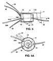
- Fig. 5Adepicts an optical coupler for a measurement using a transmission geometry
- Fig. 5Bdepicts an optical coupler for a measurement using a reflection geometry that was already described for coupling system of Fig. 4A.
- Fig. 5Cdepicts an optical coupler for a phased array system that introduce simultaneously from input ports 19, 19A, 19B and 19C radiation of known time varying pattern that form resulting introduced radiation possessing a substantial gradient of photon density in at least one direction.
- the directional introduced radiationis perturbed by a tissue inhomogeneity (e.g., a tumor, bleeding) and is detected at the detection location 21.
- tissue inhomogeneitye.g., a tumor, bleeding
- cylinder 42may include a slit opening to accommodate movement of fiber 22 so that detection port 21 may be located at several different positions.
- the tissueis examined or imaged by scanning the introduced directional field in two or three dimensions and moving the detection port over a predetermined geometry, as described in the WO 93/25145 document.
- a similar optical coupler for a two dimensional phased array systemis shown in Fig. 5D.
- a hollow box 42A filled with optical medium 12 contained within a pliable, optically transparent barrier 44includes several optical input ports 19, 19A, 19B, 19C, ..., arranged to form a two dimensional array, and a slit 49 constructed to receive detection port 21 of detection fiber 22 or an optical window.
- port 19can be used as the detection port in a backscattering geometry.
- the couplermay also include a port 50 adapted for the needle localization procedure. (If another access is needed, port 19 may be constructed to accommodate both an optical fiber or the needle.)
- the inner walls of box 42Aare lined with a reflecting material that returns photons back to fluid 44.
- the tumoris first identified by X-ray pictures taken through box 42A. While the X-ray pictures are taken, optical fluid 44 may be withdrawn to avoid high attenuation of X-rays. Then, needle 51 is placed through port 50 to mark the tumor with a metal wire. The tumor is then examined or localized using the two dimensional phased array. Ports 19 or 50 may also be used for biopsy of the localized tumor.
- Optical couplers used for ultrasound examination and magnetic resonance imaging in conjunction with the optical spectroscopyare depicted in Figs. 5E and 5F, respectively.
- the optical coupler of Fig. 5includes a port 52 constructed to accept an ultrasound probe.
- the optical coupler for magnetic resonance imagingis made of nonmagnetic materials and includes a set of MRI coils 56 located around the tissue. The tissue is imaged by using both MRI and optical techniques, wherein the image resolution may be increased using contrast agents suitable for both MRI and optical examination, as described in the WO 94/22361 application.
- the optical couplerincludes a set of optical windows instead of the input and detection fibers.
- the couplerincludes a hollow cylinder 42A, filled with optical medium 12 contained within a pliable barrier, which has three optical windows 63, 64A and 64B.
- a light beam emitted from a light source 62 of a spectrophotometer 60is directed to a selected location of input port 63 by a set of mirrors 68A and 68B and other optical elements.
- the optical systemstores the exact position of the input beam relative to the examined tissue. After migration in tissue 11, the altered light is detected at detection ports 64A or 64B using a detector 65.
- Detector 65includes, for example, an array of semiconducting detectors.
- Optical detection ports 64A or 64Bare formed from an array of detection subareas, and each subarea conveys received radiation to the corresponding semiconducting detector.
- the systemcan record intensity and exact co-ordinates of the detected radiation. Based on the known input radiation and its co-ordinates and detected radiation for the individual detector locations, the system characterizes the tissue.
- Coupler 70includes at least one source probe 72 and at least one detection probe 75.
- Source probe 72is made of approximately twenty optical fibers of 0.5 millimeter to 3 millimeter in diameter and at least one half centimeter in length.
- Input ports 73i.e., irradiation tips
- a selected structuree.g., a matrix, mosaic, circular or linear structure
- Each irradiation tip of the fibermay include an optical matching material (e.g., a plastic, a gel-like material, a coating or the like) located between the fiber and the tissue and designed to introduce light efficiently into the examined tissue.
- probe 72has one or more light coupling ports 74.
- the probehas at least two coupling ports each made of the fibers bundled together and arranged to achieve efficient coupling of light from a light source (e.g., a light bulb, a light emitting diode, a laser) to the probe.
- a light sourcee.g., a light bulb, a light emitting diode, a laser
- Detection probe 75includes one or more detection ports 76 and one or more light coupling ports 77.
- Detection probe 75has a similar design as source probe 72, but may have a larger number of individual fibers in order to collect a sufficient amount of light that has migrated in the tissue.
- the detection fibersmay also be bundled together to form a single light coupling port 77, which provides good coupling to a wide area detector (e.g., a diode detector, a PMT detector or a MCPD detector). Since source probe 72 and detection probe 75 have a similar construction, they may be used interchangeably.
- Several source probes and detection probesmay be coupled to an optical sequencer or multiplexer constructed to transmit and receive light in a desired manner. The probes are made of cladded fibers to eliminate crosstalk.
- Source probe 72 and detection probe 75are mounted on a support member constructed to achieve a selected position of the fibers and a desired separation of the input ports and the detection ports.
- the support membercan also transmit pressure to the fiber tips for improved coupling of light to the tissue.
- the hairbrush optical couplercan be used for examination of symmetrical tissue regions of the brain, breast, arm, leg or other, as is described in the WO 92/20273 application.
- the hairbrush optical couplercan be also employed to detect asymmetrical tissue properties of optically symmetrical body regions.
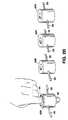
- Fig. 7Adepicts the hairbrush coupler attached to the head; specifically, to the parietal bones of a newborn which still has the characteristic opening called anterior fontanel.
- Input ports 73A and 73B of source probes 72A and 72B, respectively,are located on symmetrical locations of the corresponding parietal bones (or the temporal bones, the occipital bone, etc.).
- Detection ports 75A and 75Bare spaced the same distance ( , usually 3 cm to 8 cm) from the corresponding input ports 73A and 73B.
- the spectrophotometerintroduces radiation of a selected wavelength at each input port and detects radiation at each detection port.
- the spectrophotometerstores the detected data separately and correlates them together or with a stored data corresponding to the individual brain regions to identify any asymmetry in tissue properties.
- the spectrophotometermeasures a differential signal directly. Normal tissue provides a substantially symmetrical signal.
- a detected asymmetrymay be caused by a tissue disease, such as localized bleeding, an asymmetric stroke volume, or another pathological condition. (For example, see S.P. Gopinath et al., J. Neurosurg., 79, 1993.)
- a multifiber hairbrush probeis used for imaging of the brain.
- a series of semirigid 1 mm fibersis embedded in a styrofoam or plastic helmet.
- the input ports of the fibersproject through the hair to the surface of the scalp.
- the patient's headis covered by, for example, 4 rows of 8 fibers extending from the frontal region to the occipital region.
- a larger number of fibersis used when a higher resolution of the image is needed.
- Each fiberis coupled at its optical coupling port to an optical sequencer or multiplexer. This way any fiber may be coupled to a light source or a light detector of an optical imager described in WO 93/25145 or WO 96/16596.
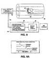
- the hairbrush optical coupleris constructed for in vivo examination of tissue using simultaneously magnetic resonance imaging (MRI) and medical optical imaging (MOI).
- the couplerincludes a styrofoam cap 85 with four rows of 8 fibers extending from frontal to occipital region of the patient's head 88 located inside an MRI magnet 90.
- the optical fibersextend through the hair to the skull and include ferrite caps.
- Each fiberis coupled at its optical coupling port to a fiber junction box 92.
- Fiber junction box 92located outside of magnet 90, has appropriate electromechanical or electro-optical switches to time sequence the switching of a fiber conduit 91 to any one of the 32 fibers coupled to the head 88.
- the systememploys any one or more fibers for transmission and any other fibers for detection.
- An MRI/MOI control center 94includes an imaging center 95 and a computer system 96, which is constructed to create and overlay the optical and magnetic images. Coordination of the optical and MRI images is achieved by MRI/optical markers. Three-dimensional markers are formed by coating the fibers with a film exhibiting a magnetically relaxed water-like signal so that each optical fiber appears on an NMR image. This way an optical image generated by the corresponding source and detector fibers is correlated to the MRI image. Importantly, such "labeled" fibers do not interfere with the NMR examination.
- Imaging center 95employs a TRS system described in US-A- 5,119,815 or in US-A- 5,386,827.
- the TRS systemincludes a Ti sapphire tunable laser that generates a series of light pulses of different wavelengths in the NIR region, sensitive to an endogenous or exogenous pigment.
- the light pulsesgenerated as shown in a timing diagram of Fig. 8A, are transmitted via fiber conduit 91 to fiber junction box 92.
- the signalsare multiplexed to the 32 fibers that transmit light to and receive light from appropriate places in the brain.
- a single optical fibermay also be connected to fiber branches which are attached to various places on the head.
- the TRS systemalso includes two 8 multi-anode micro-channel plate detectors. The detector output is send to a parallel computer that generates images congruent with the MRI scan and completed in approximately the same time as the MRI data.
- the fibersare indexed in space to form an array and are encoded appropriately by an index pad that mimics the tissue positions. This identifies the position of the fibers in the array 1 through 32 relative to a master synchronizing pulse.
- the imaging sequenceconsists of a series of pulses transmitted through the main fiber to an identified site at selected intervals (e.g., 5 nanoseconds). Each pulse generates a photon migration pattern which is received through an identified optical coupling fiber and is recognized by the central computer as originating from a certain receiving fiber or set of receiving fibers by time encoding.
- the transmitter pulsestimulates all transmit fibers in sequence. Similarly, the pattern received is a composite of all receiver positions.
- the imaging console"knows" not only the location of the fiber, but also identifies the signal received from the fiber conduit by its time sequence with respect to the synchronizing pulse.
- the transmission / reception algorithmconsists of a sequence of excitation pulses followed by photon diffusion patterns detected at the particular positions selected specifically for the organ being studied.
- the systemmay use a generic transmission /reception algorithm designed for an average organ or a patient specific algorithm. Furthermore, different algorithms may be used for ipsilateral, contralateral, de novo or recurrent brain bleeding.
- the optical couplercan be attached to the head (or any part of the body) for longer periods of time to monitor evolution of a tissue state (e.g., brain bleeding, compartment syndrome, or changes in a stroke induced volume) during and after administration of a specific drug.
- a tissue statee.g., brain bleeding, compartment syndrome, or changes in a stroke induced volume
- the systemcan also monitor evolution of a stroke induced volume or changes in intracranial pressure after administration of an osmotic agent (e.g., mannitol, glycerol), texamethasone (with its effects delayed for several hours) or another drug that temporarily reduces brain oedema.
- an osmotic agente.g., mannitol, glycerol
- texamethasonewith its effects delayed for several hours
- another drug that temporarily reduces brain oedemae.g., a solute
- solutee.g., glucose
- Computer system 96provides an overlay of the two images with contrast due to vascularity/vasculogenesis, blood vessels permeability, proliferation/degeneration of intracellular organelles, or some other tissue characteristics.
- the optical imagesneed to have an adequate contrast.
- the desired gradient of contrastis accomplished by selecting a suitable contrast agent (i.e., an exogenous pigment) and a wavelength of the introduced light.
- the spectrophotometermay construct separate images based on the scattering coefficient or the absorption coefficient.
- imaging center 95may employ an amplitude modulation system or a CW system rather than the TRS system to increase resolution for some types of images.
- Scanning coupler 160constructed for imaging of breast tissue, employs a spectroscopic imaging system described in the WO 93/25145 application or in the WO 96/16596 application.
- Scanning system 160includes an optical coupler 162, which may have cubical or cylindrical shape and is filled with optical medium 164.
- Optical coupler 162is positioned over the breast 8 near the chest wall.
- the optical matching fluide.g., twice-diluted J&J baby lotion
- the optical matching fluidis contained within a pliable, optically transparent barrier.
- the inside walls of coupler 162may be coated with a film that reflects light in the visible or near infra-red range back to the matching fluid to prevent escape of photons from the tissue surface.
- the optical couplermay be of different sizes or may have an adjustable volume so that the coupler can have a selected distance between the breast surface and the inside walls. (The preferred distance is about 1 centimeter, but for a very small tissue a larger distance is preferable to achieve semi-infinite boundary conditions.)
- the coupleris also useful for examination of a small breast or after a surgical removal of the breast tissue.
- the volume of medium 164is adjusted so that the barrier fits snugly around the examined breast 8.
- the optical mediumis a pliable solid, for example, an absorbing gel containing metallic or oxide spherical particles, silky glass beads as scatterers or a suitable plastic material.
- Fig. 9Adepicts a set of couplers 162A and 162B for simultaneous scanning of both breasts. Attached to each coupler are source-detector probes (168A, 168B, 168C, 168D, 169A, 169B, 169C, 168D), which include one or more optical sources or detectors described above. The probes are movable on a rail 170. In an automatic positioning system, each probe is connected to a servo motor (step motor) that is operated by a controller. Depending on the spectroscopic system, a fiber 172 (of Fig. 9) may be used to collect, at a detection port 174, radiation that has migrated in the examined tissue and couple the radiation to a detector. Alternatively, fiber 172 may be used to couple, at input port 174, radiation to the examined tissue.
- source-detector probes168A, 168B, 168C, 168D, 169A, 169B, 169C, 168D
- a computer controllermaintains coordinated positions of the probes to the selected combination of the transmitters and receivers.
- the scanis performed on a single breast or simultaneously on the contralateral breast.
- the sensitivity of the simultaneous scanis increased by measuring a differential signal.
- a computerdisplays the detected signal or the differential signal in a 3 dimensional coordinate system.
- a contrast agente.g., cardio-green, indocyanine-green
- cardio-green, indocyanine-greenwhich is preferentially accumulated in a tumor 9 may by injected intravenously.
- an optical coupler 181is located at a distal end of a catheter 180.
- Catheter 180includes at least two optical conduits 184 and 190, which are at the proximal end connected to a fiber junction box 182 (e.g., a muliplexer, a sequencer).
- the optical couplerincludes at least one input port 186 and at least one detection port 192, separated by a selected distance, and an optical barrier 189 constructed to prevent direct migration of the radiation between the ports.
- Input port 186 and detection port 192may also include selected optical medium 188 and 194, respectively.
- optical conduits 184 and 190Prior to the spectroscopic examination, optical conduits 184 and 190 may be used for illumination and observation of the internal tissue.
- catheter 180may include an inflatable balloon 183. When inflated, balloon 183 presses the optical ports 186 and 192, or pliable optical medium 188 and 194 to the examined tissue.
- catheter 180may include, at its distal end, an optical coupler 200, shown in Fig. 10B, which is constructed and arranged for examination or long term monitoring of brain tissue (or another tissue) of a fetus still located in the uterus.
- Optical coupler 200includes a suction ring 202 (or a suction cup) constructed to maintain optical ports 204 and 206 at a selected position, and optical medium 194.
- Catheter 180is introduced to the uterus either through the birth canal or through the maternal abdominal wall.
- optical coupler 200designed for visual and spectroscopic examination selected internal tissue, for example, cervix, uterus, gastrointestinal tract, urinary tract, bronchi, and other.
- Catheter 180is introduced to the selected tissue region via a body passage or transcutaneously.
- Optical conduits 184 and 190are first utilized to locate, visualize and examine the internal tissue by a clinician. If the clinician locates a tissue region that requires further examination, he/she positions the optical input and detection ports for spectroscopic examination utilizing a spectrophotometer optically coupled to the proximal end of catheter 180. The spectroscopic examination is performed by detecting back-scattered light that has migrated from the input port to the detection port, or by detecting fluorescent light excited in the examined tissue.
- the spectrophotometeris the above-cited CWS, TRS, PMS or phased array spectrophotometer, or a spectrophotometer described in U.S. Patents 4,930,516, 5,042,494, 5,106,387, 5,131,398, or 5,261,410.
- Catheter 180may also include a biopsy attachment for taking a biopsy specimen from a tissue region previously examined by the spectrophotometer. The biopsy is performed only if the spectroscopic examination indicates a potentially abnormal tissue. Thus the initial spectroscopic examination eliminates a substantial number of biopsies and saves the related cost.
- a spectrophotometeris disposed on a catheter 210 (e.g., an endoscopic catheter), which may include an inflatable balloon 212 and endoscope optics 214.
- the spectrophotometere.g., a TRS-pulse, PMS, CW, or phased array spectrophotometer
- the spectrophotometerincludes light sources 216 and 218 movable on tracks 217 and 219, respectively, and centrally located detectors 220 and 222.
- Optical medium 224is at least partially surrounding the sources and the detectors.
- catheter 210, with the balloon deflatedis passed through a body lumen to the position of interest, guided for example, by fluorimetry or by endoscopic viewing.
- the balloonis then inflated to press optical medium 224 against the tissue of interest.
- the technique and apparatusmay be applied, for example, to body lumens such as the GI tract (e.g., for measurements of GI track wall) or to blood vessels, employing an angiographic catheter for analysis and treatment of occlusions.
- a comprehensive systemcan serve many hospital functions including transduction of vital signals from bedside, from the OR, the ICU, or the ER to a designated computer.
- the systemmay include a large number of optrode transducers which may measure all the vital signs (blood pressure, pulse, temperature, respiration) electrocardiogram, electroencephalogram, serum electrolyte levels, and all the features of medical optical imaging (e.g., the simplest detection of hemorrhage, oxygen saturation of hemoglobin, imaging of potential dangers such as stroke, aneurysm rupture, and recurrence of brain bleeding).
- This informationcould be carried by single optical fibers with suitable transduction to whatever transmission method is optimal including highly sophisticated PCM.
Landscapes
- Health & Medical Sciences (AREA)
- Life Sciences & Earth Sciences (AREA)
- Physics & Mathematics (AREA)
- Molecular Biology (AREA)
- Animal Behavior & Ethology (AREA)
- Veterinary Medicine (AREA)
- Biophysics (AREA)
- Pathology (AREA)
- Engineering & Computer Science (AREA)
- Biomedical Technology (AREA)
- Heart & Thoracic Surgery (AREA)
- Medical Informatics (AREA)
- Public Health (AREA)
- Surgery (AREA)
- General Health & Medical Sciences (AREA)
- Spectroscopy & Molecular Physics (AREA)
- Optics & Photonics (AREA)
- Radiology & Medical Imaging (AREA)
- Neurology (AREA)
- Nuclear Medicine, Radiotherapy & Molecular Imaging (AREA)
- Gynecology & Obstetrics (AREA)
- Reproductive Health (AREA)
- Measurement Of The Respiration, Hearing Ability, Form, And Blood Characteristics Of Living Organisms (AREA)
- Investigating Or Analysing Materials By Optical Means (AREA)
- Investigating, Analyzing Materials By Fluorescence Or Luminescence (AREA)
Description
- Continuous wave (CW) spectrophotometers have beenwidely used to determinein vivo concentration of anoptically absorbing pigment (e.g., hemoglobin,oxyhemoglobin) in biological tissue. The CWspectrophotometers, for example, in pulse oximetryintroduce light into a finger or the ear lobe to measurethe light attenuation and then evaluate the concentrationbased on the Beer Lambert equation or modified BeerLambert absorbance equation. The Beer Lambert equation(1) describes the relationship between the concentrationof an absorbent constituent (C), the extinctioncoefficient (ε), the photon migration pathlength <L>, andthe attenuated light intensity (I/Io).
- Furthermore, for quantitative measurement oftissue of a small volume (e.g., a finger) photon escapeintroduces a significant error since the photons escapedfrom the tissue are counted as absorbed. Other errorsmay occur due to irregular coupling of light to theexamined tissue or varying relative geometry of the inputand detection ports.
- The time resolved (TRS-pulse) and phase modulation(PMS) spectrophotometers can measure the averagepathlength of migrating photons directly, but the properquantitation of the time resolved or frequency resolvedspectra can be performed only when the spectra arecollected at a relatively large source-detectorseparation. This separation is difficult to achieve fora small volume of tissue such as the earlobe, a finger ora biopsy tissue.
- Therefore, there is a need for an optical couplerused with a spectrophotometric system and method thatquantitatively examines a relatively small volume ofbiological tissue.
- US-A-5,090,415 discloses an examination apparatus forexamining with transmission photometry an object ofinterest. The apparatus comprises light launching meansand light pickup means. The light launching means isconstructed for successively launching an incidence lightbeam to the object at an incidence site. The lightpickup means is constructed for picking up, insynchronism with launching of the incidence light beam,light beams scattered in the object from a plurality ofoutput sites as light intensity data. The apparatusperforms mathematical processing on the light intensitydata for every launching of the incidence light beam toobtain absorption data representing a light absorptionquantity at the incidence site.
- US-A-4,321,930 discloses an apparatus for monitoringmetabolism in body organs. The apparatus includes amounting structure that secures to a selected portion ofthe human body, e.g., the head, a limb, or the torso, andincorporates light source and light detecting means. Thelight source and light detecting means are adapted forassociation with spectrophotometric circuitry for insitu, in vivo monitoring of local metabolism in the areaof the body where the structure is secured.
- PCT publication WO 94/16615 discloses a system forexamination of a volume of biological tissue usingvisible or infra-red radiation. The system includes aspectrophotometer, an optical medium having selectablescattering and absorptive properties, and a processor fordetermining a physiological property of the examinedtissue. The spectrophotometer includes a light sourcefor introducing radiation at an optical input port and adetector for detecting radiation that has migratedthrough a path from the input port to an opticaldetection port. The biological tissue is positioned intoa photon migration path inside the optical medium to create a tissue-medium optical path. The optical mediumis adapted to limit substantially escape of photons fromthe tissue. The processor determines tissue propertiesbased on the detected optical property of the tissue-mediumoptical path and the selectable properties of theoptical medium.
- The
EP publication EP 0 290 279 A1 discloses anexamination apparatus for measuring oxygenation. Theexamination apparatus measures the oxygenation of anobject by near infrared light transmissionspectrophotometry. The examination apparatus compriseslight source means; an illumination side fixture to applylight to the object, a detection side fixture to receivelight transmitted through the object, a transmitted lightdetection device to detect the light transmitted throughthe object, and a computer system to control theapparatus (1) and calculate its oxygenation. To inspectthe examination apparatus itself before the oxygenationmeasurement, the illumination-side fixture and thedetection-side fixture have such structures that enablethem to be assembled together in such a manner that lightis directly transmitted from one to the other. Duringthe measurement, the examination apparatus including itsphotomultiplier tube is regularly inspected by using aseparate inspection light source. - The present invention is directed to an optical coupling system comprising aspectrophotometer that includes at least one optical source and detector. The couplingsystem includes a source probe and a detection probe. The source probe includes at leasttwo optical fibers having distal ends positionable directly at the tissue. Each distal endforms an input port constructed to introduce optical radiation into the examined tissue.The fibers have proximal ends constructed and arranged to form at least one couplingport for receiving radiation from at least one source and for simultaneously introducingradiation into the examined tissue from at least two input ports at the distal ends. Thelight source and coupling port are co-operatively arranged for simultaneous introductionof radiation having a known time varying pattern. The detection probe includes at leastone optical fiber having a distal end positionable directly at the tissue. The distal endforms a detection port constructed to receive radiation that has migrated in the examinedtissue. The fiber has a proximal end constructed and arranged to form at least onecoupling port for conveying the detected radiation to the optical detector.
- The spectrophotometer is a continuous wavespectrophotoneter (CWS) as described in
PCT applicationsWO 92/20273 andWO 96/16592, a phase modulationspectroscopic unit (PMS) as described in U.S. Patents4,972,331, 5,187,672, or aPCT application WO 94/21173,time resolved spectroscopic (TRS) unit as described inU.S. Patent 5,119,815 or 5,386,827 or aPCT applicationWO 94/22361, or a phased array system as described in WO93/25145. - The system performs a single measurement or acontinuous, time-dependent monitoring of the selectedphysiological property.
- According to another important aspect, theinvention is an optical coupling system for non-invasivelymonitoring a region of living tissue. Thecoupling system includes at least two excitation (input) portspositionable at the tissue and adapted to introduceoptical radiation into the monitored tissue, a firstlight guide defining an excitation channel for conveyingthe radiation from a source to the excitation ports, and adetection port, positionable at the tissue, adapted toreceive radiation that has migrated in the monitoredtissue from the excitation ports to the detection port.The detection port has a detection area larger than aninput area of the excitation ports. connected to thedetection port is a detecting light guide, for conveyingthe radiation from the detection port to an opticaldetector. The coupling system also includes opticalmatching fluid contained within a flexible opticallytransparent bag and disposed partially around themonitored tissue and the excitation and detection ports.
- Preferred embodiments of this aspect of theinvention includes one or more of the following features.
- The optical coupling system may include multipleexcitation (input) ports positionable at the tissue andadapted to introduce radiation of the source into themonitored tissue, and multiple light guides, eachdefining an excitation channel for conveying theradiation from the source to the corresponding excitationport.
- The optical coupling system may also includemultiple detection ports positionable at the tissue andadapted to receive radiation that has migrated in themonitored tissue, and multiple detecting light guideseach connected to the corresponding detection port for conveying the radiation from the detection port to atleast one optical detector.
- The optical matching fluid may be positionedpartially between the ports and the monitored tissue.The optical matching fluid may have known scattering orabsorptive properties.
- The optical coupling system may further includemeans for changing scattering or absorptive properties ofthe optical matching fluid and means for calibrating thecoupling system by controllably changing scattering orabsorptive properties of the optical matching fluid.
- According to another important aspect, theinvention is an optical coupler forin vivo examinationof biological tissue. The optical coupler includes at least twooptical input ports of a selected input area positionableon or near the examined tissue, light guidesoptically coupled to the optical input ports andconstructed to transmit optical radiation of a visible orinfra-red wavelength from a source to the optical inputports, wherein the optical input ports are constructed andarranged to introduce the optical radiation to theexamined tissue, and an optical detection port of aselected detection area positionable on or near theexamined tissue. The detection port is constructed andarranged to receive radiation that has migrated in theexamined tissue from the input port to the detectionport. Optically coupled to the detection port is adetector light guide constructed to transmit theradiation from the detection port to an optical detector.The optical coupler also includes optical medium disposedat least partially around the examined tissue and theinput and detection ports and constructed to limit escapeof, or account for photons escaped from the examinedtissue.
- According to another important aspect, theinvention is an optical coupler forin vivo examinationof biological tissue. The optical coupler includes at least twooptical input ports of a selected input area directedtoward the examined tissue, an optical detection port ofa selected detection area directed toward the examinedtissue, and optical medium disposed at least partiallyaround the examined tissue and the input and detectionports. The optical medium is also placed between thetissue and the input area of the input ports and betweenthe tissue and the detection area of the detection port,and the optical medium exhibits known scattering orabsorptive properties. Optically coupled to the opticalinput port is a first light guide constructed to transmitoptical radiation of a visible or infra-red wavelengthfrom a source to the optical input ports that areconstructed and arranged to introduce the radiation tothe optical medium. The optical detection port isconstructed and arranged to receive radiation that hasmigrated in the examined tissue and the optical mediumfrom the input port to the detection port. Opticallycoupled to the detection port is a detector light guideconstructed to transmit the radiation from the detectionport to an optical detector.
- According to another important aspect, theinvention is an optical coupling system for non-invasivelymonitoring a region of biological tissue. Thecoupling system includes a source probe made of at leasttwo optical fibers having distal ends positionabledirectly at the tissue. Each distal end forms an inputport constructed to introduce optical radiation into theexamined tissue. The fibers have proximal endsconstructed and arranged to form at least one couplingport for receiving the radiation from a source. Thecoupling system also includes a detection probe made of at least one optical fiber having a distal endpositionable directly at the tissue. The distal endforms a detection port constructed to receive radiationthat has migrated in the examined tissue. The fiber hasa proximal end constructed and arranged to form at leastone coupling port for conveying the detected radiation toan optical detector.
- The optical fibers may include at the input portor at the detection port an optical matching mediumarranged to achieve a desired coupling of the radiation.
- Preferred embodiments of this aspect of theinvention includes one or more of the following features.
- The optical medium may have absorptive orscattering properties substantially matched to theabsorptive or scattering properties of the examinedtissue.
- The optical coupler may further include an opticalsystem constructed and arranged to alter controllablyabsorptive or scattering properties of the opticalmedium. The system may be adapted to substantially matchthe absorptive or scattering properties of the opticalmedium to the absorptive or scattering properties of theexamined tissue.
- The optical coupler may further include a secondinput port of a selected input area, and a light guideoptically coupled to the second input port. Thedetection port may be placed symmetrically relative tothe first input port and the second input port. Thedetection port may be arranged in a transmission geometryor in a backscattering geometry relative to the inputports.
- The optical coupler may accommodate movableoptical ports relative to the examined tissue.
- The optical coupler may further include multipleinput ports, and multiple light guides optically coupled to the corresponding input ports. The multiple inputports may be arranged to introduce simultaneouslyradiation of known time varying pattern to form resultingintroduced radiation possessing a substantial gradient ofphoton density in at least one direction. The multipleinput ports may form a one dimensional or two dimensionalarray. The optical detection port may be movable toanother location relative to the examined tissue.
- The optical coupler may also include multipledetection ports, and multiple detector light guidesoptically coupled to the corresponding detection ports.
- The optical medium may be made of a solid, liquid,or gas. The optical medium may also include solidparticles of smooth, spherical surface, or styrofoam.The optical medium may also include a liquid ofselectable scattering or absorptive properties such as anintralipid solution. The optical medium may include apliable solid of selectable scattering or absorptiveproperties.
- The optical coupler may have the detection area ofthe optical detection port is larger than the input areaof said optical input port.
- The optical coupler may further include a port forthe needle localization procedure or may be arranged forultrasonic examination of the tissue performedsimultaneously with, or subsequently to the opticalexamination of the tissue. The optical coupler mayfurther include a set of MRI coils arranged to perform anMRI examination of the tissue.
- The optical coupler may be disposed on anendoscope, catheter, guidewire or the like for insertionvia a body passage, or transcutaneously, to internaltissue. The optical coupler is designed for visual andspectroscopic examination the selected internal tissue.The catheter may include an inflatable balloon that can press the input and detection ports against the tissueselected for spectroscopic examination. The catheter mayalso include a biopsy attachment for taking a biopsyspecimen from a tissue region before or after thespectroscopic examination.
- According to another important aspect, theinvention is an optical coupler for in vivo examinationof biological tissue. The optical coupler includes at least twooptical input ports of a first selected area directedtoward the examined tissue and a second selected areaoppositely oriented to the first area, and an opticaldetection port of a selected detection area directedtoward the examined tissue. The input ports areconstructed to accept a light beam scanned over thesecond area and introduce the beam to the tissue at thefirst area. The optical coupler also includes opticalmedium disposed at least partially around the examinedtissue and the input and detection ports. The opticalmedium is also placed between the tissue and the inputarea of the input ports and between the tissue and thedetection area of the detection port. The optical mediumexhibits known scattering or absorptive properties. Theoptical detection port is constructed and arranged toreceive radiation that has migrated in the examinedtissue and the optical medium from the input port to thedetection port. optically coupled to the detection portis a detector light guide constructed to transmit theradiation from the detection port to an optical detector.
- Preferred embodiments of this aspect of theinvention includes one or more of the following features.
- The detection area of the optical detection portmay include a multiplicity of detection subareas locatedat a known position of the detection area. Eachdetection subarea is constructed and arranged to receive radiation that has migrated in the examined tissue andconvey the received radiation to a detector.
- The optical detector may include an array ofsemiconducting detectors each receiving light from acorresponding detection subarea via the detector lightguide. Thus a time profile of the detected radiation canbe measured at the individual locations.
- The light beam may be scanned over the input portusing a selected pattern relative to a detection sequenceaccumulated over the detection subareas. Then, byknowing the input and detection locations of themigrating photons, average photon migration paths may becalculated.
- In general, the optical coupling system providesan excellent coupling of light to the examined tissue.The coupling system may also substantially prevent escapeof photons from the tissue surface and achieve semi-infiniteboundary conditions for the introducedradiation. A larger volume of optical medium is usuallyused for a small tissue size. The optical couplingsystem also achieves precisely a selected geometry of theinput (excitation) ports and the detection portsregardless of the tissue shape or property. The precisegeometry is frequently important for proper evaluation ofthe photon migration patterns measured by the continuouswave (CWS) unit, the phase modulation unit, the TRS unit,or the phased array unit.
- Fig. 1 is a diagrammatic view of aspectrophotometric system for examination of tissue of arelatively small dimension.
- Figs. 2 and 2A show different views of a cylinderfor preventing escape of photons duringspectrophotometric measurements of a finger.
- Fig. 2B shows a set of cylinders of preselectedoptical properties for a finger oximetry.
- Fig. 3 is a diagrammatic view of an optical fiberholder for a spectrophotometric study of the head.
- Fig. 4 a plan view of an optical coupling systemfor monitoring the oxygenation-deoxygenation state of thehemoglobin within the brain tissue of a subject.
- Fig. 4A depicts an optical coupling system forexamination of the brain tissue utilizing several inputand detection ports.
- Figs. 5 through 5C depict several optical couplingsystems for optical examination of the breast tissue.
- Fig. 5D depicts an optical coupling system with atwo dimensional input array also adapted for the needlelocalization procedure.
- Figs. 5E and 5F depict optical coupling systemsadapted for optical examination together with ultrasoundand magnetic resonance imaging, respectively.
- Fig. 6 depicts an optical coupling system withoptical windows adapted for a scanning system with anarray detector.
- Figs. 7 and 7A depict a "hairbrush" opticalcoupling system for optical examination of the brain.
- Figs. 8 and 8A depict a "hairbrush" opticalcoupling system for optical and MRI examination.
- Figs. 9 and 9A depict a scanning coupling systemconstructed for examination of breast tissue.
- Figs. 10, 10A and 10B depict an optical couplerdisposed on a catheter.
- Figs. 11 and 11A depict a spectrophotometerdisposed on a catheter.
- Fig. 1-3 all show only one one optical fiber forming an input port.These embodiments do not constitute a portion of the inventionand are discussed for explanatory purposes only.
- Referring to Fig. 1, the basic principle ofoperation of different optical couplers is explained bydescribing a
system 10.System 10, designed forexamination of biological tissue of a relatively smallvolume, includes anoptical medium 12 of selectableoptical properties, aspectrophotometer 18, atitrimetriccirculation system 30, andcomputer control 35.Biological tissue ofinterest 14, attached to alocator 15, is immersed inoptical medium 12.Spectrophotometer 18 examines optical properties ofmedium 12 by employingvisible or infra-red light conducted via light guides 20and 22. Light guides 20 and 22, which in a preferredembodiment are optical fibers, are connected to alightsource 17 and alight detector 23, respectively. Photonsintroduced at anoptical input port 19 migrate inmedium 12 through a scattering and absorptive path and aredetected at adetection port 21. The selectable fixedgeometry ofinput port 19 anddetection port 21 controlsthe migration path, i.e.,optical field 25. System 30 is adapted to change precisely thescattering and absorptive properties ofmedium 12.Medium 12 includes intralipid solution (made by KabiVitrum, Inc., Clapton, NC) that exhibits scatteringproperties depending on its concentration and carbonblack india ink that exhibits absorptive properties. Thescattering or absorptive properties of medium 12 can beeither maintained constant and uniform by properly mixingthe solution or can be changed almost continuously bychanging the concentration of the constituents intitration system 30.Tubes - In system operation,
tissue 14 is first locatedaway fromoptical field 25.Spectrophotometer 18examines medium 12 infield region 25, andcontrol 35 compares the detected data to the preselected values ofthe absorption coefficient (µa) and the scatteringcoefficient (µs). Next,locator 15positions tissue 14intofield 25 andspectrophotometer 18 measures theoptical properties oftissue 14 andmedium 12. From thespectral data collected with and withouttissue 14,computer control 35 determines the optical properties oftissue 14. - In another preferred method of operation, aftermeasuring the optical properties of
medium 12, thescattering and absorptive properties ofmedium 12 arematched by titration to the properties oftissue 14 sothat, when inserted intofield 25,tissue 14 does notcause perturbation offield 25. After matching thescattering and absorption coefficients of medium 12 tothe coefficients oftissue 14,spectrophotometer 18detects the same data with or withouttissue 14. Theknown titrated values of µa* and µs* are equal to the µaand µs values oftissue 14. The matching process isperformed by first matching µa and then µs or vice versa. - The described method is applicable to both in vivoand in vitro tissue examination.
Tissue 14 may be abiopsy specimen enclosed in an optically transparentmaterial or a portion of a human finger inserted intomedium 12. The wavelength of light used byspectrophotometer 18 is selected depending on the tissuecomponent of interest (e.g., hemoglobin, oxyhemoglobin,glucose, enzymes); it is within the scope of thisinvention to use multiple wavelengths. - The present invention envisions the use ofdifferent preferred embodiments of
optical medium 12.Referring to Fig. 2, ahollow cylinder 42 filled withmedium 12 surrounds, for example, afinger 40 andprevents escape of introduced photons. The opticalproperties, pressure and volume ofmedium 12 are controlled bysystem 30 connected tocylinder 42 bytubes cylinder 42 are made of apliable, opticallytransparent barrier 44. Afterinsertion intocylinder 42,barrier 44 fits snugly aroundthe finger. The dimension ofinside barrier 44 is suchthat afterfinger 40 is withdrawn, medium 12 fills thevolume ofcylinder 42 completely. This enables both abackground measurement ofmedium 12 and a measurement offinger 40 inmedium 12 in the same way as described inconnection with Fig. 1.Optical field 25, controlled bythe position ofinput port 19 anddetection port 21, iseither in transmission or reflection geometry. - Referring to Fig. 2B, in another embodiment,
cylinder 42 is replaced by a set ofcylinders medium 12 in a fluid or solidstate with a constant preselected absorption andscattering coefficient. The solid optical medium istitanium oxide, or other scatterer, imbedded in anabsorbing, pliable medium such as a gel. - A human finger is inserted into the individualcylinders, and the optical properties of the insertedfinger are measured by
spectrophotometer 18. Using theknown optical properties of the cylinders and the input portdetection port geometry, the optical properties (i.e.,µa and µs) of the finger can be matched to the propertiesof one of the cylinders. - The preferred embodiments of
spectrophotometer 18are a continuous wave spectrometer, a phase modulationspectrometer and a time-resolved spectrometer, all ofthem described in the above-cited documents. System 10 operating with a dual wavelengthcontinuous wave spectrometer is used, for example, as afinger oximeter. As shown in Fig. 2A, the vast majorityof photons introduced intofinger 40 are prevented toescape by surroundingmedium 12. Thus, the introduced photons are either absorbed or reachdetection port 21and are registered by the detector. No error of countingthe escaped photons as absorbed occurs. The backgroundspectral data corresponding to each selected value of µa*and µs* ofcylinder 42 are stored in the system that canmatch the values of µa and µs of the finger and thecylinder for each wavelength. For the continuous wavespectrometer that operates at two wavelengths sensitiveto hemoglobin (Hb) and oxyhemoglobin (HbO2) (e.g., 754nmand 816nm), the hemoglobin saturation (Y) is calculatedby taking the ratio of absorption coefficients and usingthe following equation for the oxygen saturation:- As known to a person skilled in the art, in thehemoglobin saturation measurement the oximeter normalizesthe detected data to eliminate fluctuations due to thechanging blood volume. However, the volume changes canbe used to detect the pulse rate.
- Alternatively, a phase modulation spectrometer isused to measure the photon migration by detecting theintensity and the phase shift of sinusoidally modulatedlight introduced at a distance of several centimetersfrom the detector. For tissue of a small volume, theoptimal distance between the input port and theirradiation port is achieved using
optical medium 12. Furthermore, medium 12 substantially eliminates thephoton escape. - The detected phase shift is directly related tothe mean of the distribution of photon pathlengths shownin Fig. 2A. Photon migration theory predicts that thedetected photons can be represented by a threedimensional "banana-shaped" distribution pattern in thereflection geometry or a "cigar-shaped" distributionpattern in the transmission geometry. Inserting
tissue 14 into the center offield 25 causes nonuniformities inthe distribution of pathlengths, i.e., the banana-shapedoptical field 25 is nonuniform, if the tissue absorptionproperties are different from the properties ofmedium 12. If µa of the tissue is smaller then that of thesurrounding medium, the average pathlength <L> decreasessince photons with longer pathlengths are more absorbedand vice versa. Thus,tissue 14 causes changes in thepathlength and the phase shift, . - Furthermore, the detected intensity provides amodulation index (M) that is an important measure of theabsorption and scattering properties of a stronglyscattering medium. The modulation index is determined asthe ratio of the AC amplitude (Aλ) to the sum of the ACand DC (DCλ) amplitude.
- As described in Sevick et al. in AnalyticalBiochemistry Vol. 195, pp. 330-351, 1991,for low modulationfrequencies (i.e., 2πf << µac) the phase shift is adirect measure of the mean time of flight, <t>, i.e.,→2πf<t>. In a medium wherein all photons travel at aconstant speed, c, the phase shift describes theeffective, mean pathlength → 2πf<L>/c. Here, all pathlengths are weighted equally. The determinedpathlength is used in Beer-Lambert equation fordetermination of the absorption properties.
- As the modulation frequency increases, the shorterpathlengths become more heavily weighted. At high frequencies(i.e. 2πf >> µac), the phase shift is no longer a goodmeasure of the distribution of pathlengths and isdirectly proportional to the absorption coefficient, µa,and the effective scattering coefficient, (1-g)•µs
- Alternatively, a time-resolved spectrometer (TRS-pulse)is employed which introduces, at
input port 19,pulses of light on the order of less than a picosecond.Photons traveling through a distribution ofmigrationpathlengths 25 are collected at thedetection port 21. The intensity of detected light in the reflectancegeometry, R(ρ,t), (or the transmittance geometryT(ρ,d,t)) was determined by solving the diffusionequation in an infinite media as a Green's function withnear infinite boundary conditions. Due to the semi-infinitemedia condition in the reflectance geometry, theseparation of the input and output ports must be on theorder of several centimeters to use the followingequation. - For t → ∞ the absorption coefficient µa isdetermined aswherein ρ is the separation between input and detectionports and c is speed of light in the medium. Theeffective scattering coefficient (1-g) µs is determinedas

tissue 14. Alternatively, µaand µs ofmedium 12 andtissue 14 are matched by varyingthe scattering and absorptive properties of medium 12 sothat the detected time profile is not altered byintroducingtissue 14. - The TRS system can be used to calibrate a CWoximeter to quantify the measured data. To account forthe difference between the geometric distance (ρ) of theinput port and the detection port and the pathlength(<L>), some oximeters use a modified Beer-Lambertequation with a differential pathlength factor (DPF) asfollows:
- Alternatively, a phased array spectrometer,described in WO 93/25145, is employed to localize atissue anomaly or image a selected tissue region.
- The described systems are constructed to performeither a single measurement or a continuous, time-dependentmonitoring of the selected physiologicalproperty. The may include a visual display forcontinuous monitoring of the measured values and mayinclude a alarm that issues a warning signal when themeasured value equals to a preselected value.
- An alternative embodiment of the optical coupleris an
optrode holder 45 shown in Fig. 3.Optrode holder 45 is used for examination of the head of a neonate (46).Optical fibers photons 48. The pathlength of themigrating photons in the tissue is much longer since thephotons return to the tissue by the scattering materials,as shown by the zig-zag arrows 48. Thus, the banana-shapedpattern will penetrate more deeply and meaningfulspectroscopic data can be obtained at smaller input-outputfiber separations without the danger of photonleakage or "short" by substantially direct pathways.Alternatively, the styrofoam may be replaced by ametallic foil that reflects back to the tissue radiationof visible or near infrared wavelengths. The foilsurrounds the input and detection ports and the examinedtissue. - Referring to Fig. 4, another embodiment is anoptical coupling system that comprises an
opticalcoupling device 114 and a spacer-coupler 116 for couplingthe forward end ofoptical coupling device 114 to theback of thehead 110 to monitor a tissue region of thebrain. (A similar system can monitor other tissueregions, such as internal organs and muscles.) Thespacer-coupler 116 is a thin, flexible, liquid-filled bagthat is inflated by optical matching fluids to thecondition depicted. The spacer-coupler 116 also servesas a cushion, providing a soft interface between theforward end of thecoupling device 114 and thehead 110. - The
optical coupling device 114 comprises alightguide 120 in the form of a bundle of optical fibersconstituting an excitation channel for supplying near redradiation (NR) from the rear of the coupling device tohead 110. Thedistal end 121 of thelight guide 120adjacent thehead 110 forms an excitation port. Adetectinglight guide 124, which is also comprised of optical fibers, extends along the length of the couplingdevice. Surrounding adistal end 125 of detectinglightguide 124 is an opaquespecular barrier 122. The barrierblocks substantially all direct and reflected radiationexcept that migrating from a region spaced from thetissue surface; i.e.,barrier 122 acts as an absorber ofthe near-surface rays. This enables the connectedspectrophotometer to determine, for example, theoxygenation state of hemoglobin deep within the tissuerather than at the surface. To block the leakage of theradiation from the length of the excitation light guideinto the detecting light guide, athin coating 130 ofmaterial substantially opaque to the radiation ispreferably placed around each of the fiber optic bundles120, 124. - The monitoring systems of Fig. 4 can be calibratedby the flowing of a mixture of yeast cells and blood ofknown oxygenation properties through the spacer-
coupler 116 to determine the ab initio sensitivity of the systemto oxy-deoxy-hemoglobin solutions of blood. The accuracyof the monitoring system can be improved by compensatingfor changes of the albedo of the hair and skin of thesubject and also for changes in the thickness of thespacer-coupler 116. Such compensation can be achieved byproviding an annulus of optical fibers closelysurrounding theexcitation light guide 120, but separatedtherefrom by an opaque coating. The excitation radiationsupplied through thelight guide 120 and detected by theannulus of fibers at the forward end of the couplingdevice can be used to monitor the backscattered radiationand also regulate the lamp intensity so as to maintainconstant incident radiation. - A similar coupling system is shown in Fig. 4A.The coupling system includes a spacer-
coupler 116 and twosets ofexcitation ports detection ports detection ports tubes - Each row of the excitation ports and the detectionports may be used for independent examination of thebrain tissue by performing a ρ-scan as described in aWO 96/16592.Light guides deliver radiation to
individualexcitation ports detection ports - The central row of
detection ports excitationports detection port 126A is located on a null plane of equal intensity in thetissue. A detector detects sequentially radiation thathas migrated from theinput ports detection port 126A. The detected signals are stored ina sample-and-hold circuit and subtracted in a subtractioncircuit to create a differential signal. Thedifferential signal is then used to examine the tissue.This cancellation measurement is performed over the threesets of excitation and detection ports (i.e., 121A,121A', and 126A; 121B, 121B', and 126B; 121C, 121C', and126C, respectively) to examine the frontal lobe of thebrain. - Referring to Fig. 5, similar type of the opticalcoupling system is used to examine
breast tissue 11. Acylindrical optical coupler includes ahollow cylinder 42filled withoptical medium 12.Cylinder 42 is placedover thebreast 11 near thechest wall 11A. As describedabove, the optical properties, pressure and volume ofmedium 12 are controlled bysystem 30 connected tocylinder 42 bytubes transparentbarrier 44. The inside walls ofcylinder 42 may becoated with a film that reflects light in the visible ornear infra-red range back to the matching fluid. Theoptical coupler usescylinders 42 of different sizes or acylinder with an adjustable volume so that the couplercan have a selected distance between the breast surfaceand the inside wall ofcylinder 42. The preferreddistance is about 1 centimeter, but for a very smalltissue a larger distance is preferable to achieve semi-infiniteboundary conditions. Thus the coupler is also useful for examination of the breast of a small size orafter a surgical removal of the breast tissue. Afterplacement ofcylinder 42, the volume ofmedium 12 isadjusted so thatbarrier 44 fits snugly around theexamined breast. Alternatively, the optical medium is apliable solid, for example, an absorbing gel containingmetallic or oxide spherical particles, or silky glassbeads as scatterers. When the cylinder is placed firmlyon the examined breast, the excess optical mediumcontained within the pliable barrier is pushed outside ofthe cylinder. - As described above,
spectrophotometer 18 measuresthe optical properties oftissue 11 andmedium 12. Lightguides 20 and 20A are connected tolight source 21, andlight guide 22 is connected tolight detector 23.Photons introduced at anoptical input ports medium 12 over scattering and absorptive pathsand are detected atdetection port 21. The opticalmedium achieves a uniform coupling of light to the tissuethat is usually pliable and enables preselected fixedgeometry of the input end detection ports.Spectrophotometer 18, which is a continuous wavespectrophotometer, a phase modulation spectrophotometeror time resolved spectrophotometer, evaluates the breasttissue similarly as described above for the biopsyspecimen or the finger. - Furthermore, the optical resolution may beincreased when
spectrophotometer 18 together with theoptical coupler are calibrated on a "normal" tissueregion and then used to examine another tissue regionthat when "normal" should have the same opticalproperties as the first tissue region. For example, theoptical coupler is first placed on the left breast andthe optical properties of the tissue are measured. Then,the optical coupler is placed on the right breast suspected to have an abnormal tissue region. The opticalproperties of the right breast are measured and evaluatedrelative to the optical properties of the normal tissueof the left breast. The relative measurement can beperformed by measuring the two sets of data independentlyand subtracting them or comparing them to each other.Alternatively, two spectrophotometers, each with anoptical coupler placed on one breast, are usedsimultaneously using a lateralization detector. Suchtechnique is described in general (and specifically forexamination the brain) in a PCT application WO 92/20273,filed May 18, 1992. - Alternatively,
spectrophotometer 18 is a phasedarray system described in the WO 96/16596cited above. Fig. 5A depicts an optical coupler for ameasurement using a transmission geometry, and Fig. 5Bdepicts an optical coupler for a measurement using areflection geometry that was already described forcoupling system of Fig. 4A. Fig. 5C depicts an opticalcoupler for a phased array system that introducesimultaneously frominput ports detection location 21.cylinder 42 mayinclude a slit opening to accommodate movement offiber 22 so thatdetection port 21 may be located at severaldifferent positions. The tissue is examined or imaged byscanning the introduced directional field in two or threedimensions and moving the detection port over apredetermined geometry, as described in the WO 93/25145document. - A similar optical coupler for a two dimensionalphased array system is shown in Fig. 5D. A
hollow box 42A filled with optical medium 12 contained within apliable, opticallytransparent barrier 44 includesseveraloptical input ports slit 49constructed to receivedetection port 21 ofdetectionfiber 22 or an optical window. Alternatively,port 19can be used as the detection port in a backscatteringgeometry. The coupler may also include aport 50 adaptedfor the needle localization procedure. (If anotheraccess is needed,port 19 may be constructed toaccommodate both an optical fiber or the needle.) Theinner walls ofbox 42A are lined with a reflectingmaterial that returns photons back tofluid 44. When thecoupler is used in the needle localization procedure, thetumor is first identified by X-ray pictures taken throughbox 42A. While the X-ray pictures are taken,opticalfluid 44 may be withdrawn to avoid high attenuation of X-rays.Then, needle 51 is placed throughport 50 to markthe tumor with a metal wire. The tumor is then examinedor localized using the two dimensional phased array.Ports - Optical couplers used for ultrasound examinationand magnetic resonance imaging in conjunction with theoptical spectroscopy are depicted in Figs. 5E and 5F,respectively. Referring to Fig. 5E, the optical couplerof Fig. 5 includes a
port 52 constructed to accept anultrasound probe. Referring to Fig. 5F, the opticalcoupler for magnetic resonance imaging is made of nonmagneticmaterials and includes a set of MRI coils 56located around the tissue. The tissue is imaged by usingboth MRI and optical techniques, wherein the imageresolution may be increased using contrast agents suitable for both MRI and optical examination, asdescribed in the WO 94/22361 application. - Referring to Fig. 6, in another embodiment, theoptical coupler includes a set of optical windows insteadof the input and detection fibers. The coupler includesa
hollow cylinder 42A, filled with optical medium 12contained within a pliable barrier, which has threeoptical windows light source 62 of aspectrophotometer 60, isdirected to a selected location ofinput port 63 by a setofmirrors tissue 11, the altered light is detected atdetectionports detector 65.Detector 65includes, for example, an array of semiconductingdetectors.Optical detection ports - Referring to Fig. 7, another embodiment of theoptical coupling system is a hairbrush
optical coupler 70. This optical coupler is designed to provide optimalcoupling of light to and from brain tissue in regionswhere the skull is covered by hair.Coupler 70 includesat least onesource probe 72 and at least onedetectionprobe 75.Source probe 72 is made of approximatelytwenty optical fibers of 0.5 millimeter to 3 millimeterin diameter and at least one half centimeter in length. Input ports 73 (i.e., irradiation tips) of the fibers ofsource probe 72 are arranged to form a selected structure(e.g., a matrix, mosaic, circular or linear structure)depending on the desired input geometry and the type ofthe examined tissue. Each irradiation tip of the fibermay include an optical matching material (e.g., aplastic, a gel-like material, a coating or the like)located between the fiber and the tissue and designed tointroduce light efficiently into the examined tissue. Atthe proximal end,probe 72 has one or morelight couplingports 74. The probe has at least two coupling ports eachmade of the fibers bundled together and arranged toachieve efficient coupling of light from a light source(e.g., a light bulb, a light emitting diode, a laser) tothe probe. Detection probe 75 includes one ormore detectionports 76 and one or morelight coupling ports 77.Detection probe 75 has a similar design assource probe 72, but may have a larger number of individual fibers inorder to collect a sufficient amount of light that hasmigrated in the tissue. At the proximal end, thedetection fibers may also be bundled together to form asinglelight coupling port 77, which provides goodcoupling to a wide area detector (e.g., a diode detector,a PMT detector or a MCPD detector). Sincesource probe 72 anddetection probe 75 have a similar construction,they may be used interchangeably. Several source probesand detection probes may be coupled to an opticalsequencer or multiplexer constructed to transmit andreceive light in a desired manner. The probes are madeof cladded fibers to eliminate crosstalk.Source probe 72 anddetection probe 75 are mountedon a support member constructed to achieve a selectedposition of the fibers and a desired separation of theinput ports and the detection ports. The support membercan also transmit pressure to the fiber tips for improvedcoupling of light to the tissue. A connectedspectrophotometer (such as a TRS-pulse, PMS, CW, orphased array spectrophotometer) probes deep tissue atlarge separations of the ports (= 5 cm to 10 cm) andprobes a dermal layer at small separations (
= 0.5 cm to2 cm).
- The hairbrush optical coupler can be used forexamination of symmetrical tissue regions of the brain,breast, arm, leg or other, as is described in the WO92/20273 application. The hairbrush optical coupler canbe also employed to detect asymmetrical tissue propertiesof optically symmetrical body regions. Fig. 7A depictsthe hairbrush coupler attached to the head; specifically,to the parietal bones of a newborn which still has thecharacteristic opening called anterior fontanel.
Inputports 73A and 73B of source probes 72A and 72B,respectively, are located on symmetrical locations of thecorresponding parietal bones (or the temporal bones, theoccipital bone, etc.).Detection ports , usually 3 cm to 8 cm) fromthe corresponding
input ports 73A and 73B. Thespectrophotometer introduces radiation of a selectedwavelength at each input port and detects radiation ateach detection port. The spectrophotometer stores thedetected data separately and correlates them together orwith a stored data corresponding to the individual brainregions to identify any asymmetry in tissue properties.Alternatively, the spectrophotometer measures adifferential signal directly. Normal tissue provides asubstantially symmetrical signal. A detected asymmetry may be caused by a tissue disease, such as localizedbleeding, an asymmetric stroke volume, or anotherpathological condition. (For example, see S.P. Gopinathet al., J. Neurosurg., 79, 1993.) - In another embodiment, a multifiber hairbrushprobe is used for imaging of the brain. For thispurpose, a series of semirigid 1 mm fibers is embedded ina styrofoam or plastic helmet. When the helmet isattached to the head, the input ports of the fibersproject through the hair to the surface of the scalp.The patient's head is covered by, for example, 4 rows of8 fibers extending from the frontal region to theoccipital region. A larger number of fibers is used whena higher resolution of the image is needed. Each fiberis coupled at its optical coupling port to an opticalsequencer or multiplexer. This way any fiber may becoupled to a light source or a light detector of anoptical imager described in WO 93/25145 or WO 96/16596.
- Referring to Fig. 8, in another embodiment, thehairbrush optical coupler is constructed for in vivoexamination of tissue using simultaneously magneticresonance imaging (MRI) and medical optical imaging(MOI). The coupler includes a
styrofoam cap 85 with fourrows of 8 fibers extending from frontal to occipitalregion of the patient'shead 88 located inside anMRImagnet 90. The optical fibers extend through the hair tothe skull and include ferrite caps. Each fiber iscoupled at its optical coupling port to afiber junctionbox 92.Fiber junction box 92, located outside ofmagnet 90, has appropriate electromechanical or electro-opticalswitches to time sequence the switching of afiberconduit 91 to any one of the 32 fibers coupled to thehead 88. The system employs any one or more fibers fortransmission and any other fibers for detection. An MRI/MOI control center 94 includes animaging center 95and acomputer system 96, which is constructed to createand overlay the optical and magnetic images.Coordination of the optical and MRI images is achieved byMRI/optical markers. Three-dimensional markers areformed by coating the fibers with a film exhibiting amagnetically relaxed water-like signal so that eachoptical fiber appears on an NMR image. This way anoptical image generated by the corresponding source anddetector fibers is correlated to the MRI image.Importantly, such "labeled" fibers do not interfere withthe NMR examination. Imaging center 95 employs a TRS system describedin US-A- 5,119,815 or in US-A- 5,386,827. TheTRS system includes a Ti sapphire tunable laser thatgenerates a series of light pulses of differentwavelengths in the NIR region, sensitive to an endogenousor exogenous pigment. The light pulses, generated asshown in a timing diagram of Fig. 8A, are transmitted viafiber conduit 91 tofiber junction box 92. Atfiberjunction box 92, the signals are multiplexed to the 32fibers that transmit light to and receive light fromappropriate places in the brain. A single optical fibermay also be connected to fiber branches which areattached to various places on the head. The TRS systemalso includes two 8 multi-anode micro-channel platedetectors. The detector output is send to a parallelcomputer that generates images congruent with the MRIscan and completed in approximately the same time as theMRI data.- To achieve proper coupling, the fibers are indexedin space to form an array and are encoded appropriatelyby an index pad that mimics the tissue positions. Thisidentifies the position of the fibers in the array 1through 32 relative to a master synchronizing pulse. The imaging sequence consists of a series of pulsestransmitted through the main fiber to an identified siteat selected intervals (e.g., 5 nanoseconds). Each pulsegenerates a photon migration pattern which is receivedthrough an identified optical coupling fiber and isrecognized by the central computer as originating from acertain receiving fiber or set of receiving fibers bytime encoding. The transmitter pulse stimulates alltransmit fibers in sequence. Similarly, the patternreceived is a composite of all receiver positions. Theimaging console "knows" not only the location of thefiber, but also identifies the signal received from thefiber conduit by its time sequence with respect to thesynchronizing pulse. The transmission / receptionalgorithm consists of a sequence of excitation pulsesfollowed by photon diffusion patterns detected at theparticular positions selected specifically for the organbeing studied.
- The system may use a generic transmission /receptionalgorithm designed for an average organ or apatient specific algorithm. Furthermore, differentalgorithms may be used for ipsilateral, contralateral, denovo or recurrent brain bleeding. The optical couplercan be attached to the head (or any part of the body) forlonger periods of time to monitor evolution of a tissuestate (e.g., brain bleeding, compartment syndrome, orchanges in a stroke induced volume) during and afteradministration of a specific drug. For example, thesystem can also monitor evolution of a stroke inducedvolume or changes in intracranial pressure afteradministration of an osmotic agent (e.g., mannitol,glycerol), texamethasone (with its effects delayed forseveral hours) or another drug that temporarily reducesbrain oedema. The system can also monitor evolution of a solute (e.g., glucose) as it equilibrates in thebloodstream.
Computer system 96 provides an overlay of the twoimages with contrast due to vascularity/vasculogenesis,blood vessels permeability, proliferation/degeneration ofintracellular organelles, or some other tissuecharacteristics. To properly correlate the opticalimages to the NMR images, the optical images need to havean adequate contrast. The desired gradient of contrastis accomplished by selecting a suitable contrast agent(i.e., an exogenous pigment) and a wavelength of theintroduced light. The spectrophotometer may constructseparate images based on the scattering coefficient orthe absorption coefficient. Furthermore,imaging center 95 may employ an amplitude modulation system or a CWsystem rather than the TRS system to increase resolutionfor some types of images.- Referring to Figs. 9 and 9A, another embodiment ofthe optical coupling system a
scanning coupler 160.Scanning coupler 160, constructed for imaging of breasttissue, employs a spectroscopic imaging system describedin the WO 93/25145 application or in the WO 96/16596application.Scanning system 160 includes anopticalcoupler 162, which may have cubical or cylindrical shapeand is filled with optical medium 164.Optical coupler 162 is positioned over thebreast 8 near the chest wall.As described above, the optical properties, pressure andvolume of medium 164 may be controlled by an externalsystem connected to the coupler by a set of tubes. Theoptical matching fluid (e.g., twice-diluted J&J babylotion) is contained within a pliable, opticallytransparent barrier. The inside walls ofcoupler 162 maybe coated with a film that reflects light in the visibleor near infra-red range back to the matching fluid toprevent escape of photons from the tissue surface. The optical coupler may be of different sizes or may have anadjustable volume so that the coupler can have a selecteddistance between the breast surface and the inside walls.(The preferred distance is about 1 centimeter, but for avery small tissue a larger distance is preferable toachieve semi-infinite boundary conditions.) Thus thecoupler is also useful for examination of a small breastor after a surgical removal of the breast tissue. Afterplacement ofcoupler 162, the volume of medium 164 isadjusted so that the barrier fits snugly around theexaminedbreast 8. Alternatively, the optical medium is apliable solid, for example, an absorbing gel containingmetallic or oxide spherical particles, silky glass beadsas scatterers or a suitable plastic material. - Fig. 9A depicts a set of
couplers rail 170. In an automaticpositioning system, each probe is connected to a servomotor (step motor) that is operated by a controller.Depending on the spectroscopic system, a fiber 172 (ofFig. 9) may be used to collect, at adetection port 174,radiation that has migrated in the examined tissue andcouple the radiation to a detector. Alternatively,fiber 172 may be used to couple, atinput port 174, radiationto the examined tissue. - In an electro-optic scan, a computer controllermaintains coordinated positions of the probes to theselected combination of the transmitters and receivers.The scan is performed on a single breast orsimultaneously on the contralateral breast. Thesensitivity of the simultaneous scan is increased bymeasuring a differential signal. A computer displays the detected signal or the differential signal in a 3dimensional coordinate system. To increase theresolution, a contrast agent (e.g., cardio-green,indocyanine-green) which is preferentially accumulated ina
tumor 9 may by injected intravenously. Several scans areperformed to observe the time dependence of the decay andidentify a location of a suspected anomaly. The systemcan also calculate the scattering coefficient andabsorption coefficient of the suspected anomaly and thesurrounding tissue. - Referring to Figs. 10 and 10A, in anotherembodiment, an
optical coupler 181 is located at a distalend of acatheter 180.Catheter 180 includes at leasttwooptical conduits input port 186 and at least onedetectionport 192, separated by a selected distance, and anoptical barrier 189 constructed to prevent directmigration of the radiation between the ports.Input port 186 anddetection port 192 may also include selectedoptical medium optical conduits catheter 180 mayinclude aninflatable balloon 183. When inflated,balloon 183 presses theoptical ports - Alternatively,
catheter 180 may include, at itsdistal end, anoptical coupler 200, shown in Fig. 10B,which is constructed and arranged for examination or longterm monitoring of brain tissue (or another tissue) of afetus still located in the uterus.Optical coupler 200includes a suction ring 202 (or a suction cup) constructed to maintainoptical ports optical medium 194.Catheter 180is introduced to the uterus either through the birthcanal or through the maternal abdominal wall. - Alternatively,
optical coupler 200 designed forvisual and spectroscopic examination selected internaltissue, for example, cervix, uterus, gastrointestinaltract, urinary tract, bronchi, and other.Catheter 180is introduced to the selected tissue region via a bodypassage or transcutaneously.Optical conduits catheter 180. The spectroscopic examination isperformed by detecting back-scattered light that hasmigrated from the input port to the detection port, or bydetecting fluorescent light excited in the examinedtissue. Depending on the type of examination, thespectrophotometer is the above-cited CWS, TRS, PMS orphased array spectrophotometer, or a spectrophotometerdescribed in U.S. Patents 4,930,516, 5,042,494,5,106,387, 5,131,398, or 5,261,410. Catheter 180 may also include a biopsy attachmentfor taking a biopsy specimen from a tissue regionpreviously examined by the spectrophotometer. The biopsyis performed only if the spectroscopic examinationindicates a potentially abnormal tissue. Thus theinitial spectroscopic examination eliminates asubstantial number of biopsies and saves the relatedcost.- Referring to Figs. 11 and 11A, in anotherembodiment, a spectrophotometer is disposed on a catheter 210 (e.g., an endoscopic catheter), which may include an
inflatable balloon 212 andendoscope optics 214. Thespectrophotometer (e.g., a TRS-pulse, PMS, CW, or phasedarray spectrophotometer) includeslight sources tracks detectors Optical medium 224 is at least partially surrounding the sources and thedetectors. In operation,catheter 210, with the balloondeflated, is passed through a body lumen to the positionof interest, guided for example, by fluorimetry or byendoscopic viewing. The balloon is then inflated topress optical medium 224 against the tissue of interest.The technique and apparatus may be applied, for example,to body lumens such as the GI tract (e.g., formeasurements of GI track wall) or to blood vessels,employing an angiographic catheter for analysis andtreatment of occlusions. - A comprehensive system can serve many hospitalfunctions including transduction of vital signals frombedside, from the OR, the ICU, or the ER to a designatedcomputer. The system may include a large number ofoptrode transducers which may measure all the vital signs(blood pressure, pulse, temperature, respiration)electrocardiogram, electroencephalogram, serumelectrolyte levels, and all the features of medicaloptical imaging (e.g., the simplest detection ofhemorrhage, oxygen saturation of hemoglobin, imaging ofpotential dangers such as stroke, aneurysm rupture, andrecurrence of brain bleeding). This information could becarried by single optical fibers with suitabletransduction to whatever transmission method is optimalincluding highly sophisticated PCM.


Claims (27)
- An optical coupling systemcomprising:a spectrophotometer including at least one optical source and a detector;a source probe including at least two optical fibers (20, 20A, 20B, 20C, 72,72A, 72B, 120) having distal ends positionable directly at the tissue, each saiddistal end forming an input port (19, 19A, 73, 73A, 73B, 121) constructed tointroduce optical radiation into the examined tissue, said fibers having proximalends constructed and arranged to form at least one coupling port (74, 74A, 74B)for receiving said radiation from said at least one source and for simultaneouslyintroducing radiation into the examined tissue from at least two input ports at saiddistal ends; said at least one source and said at least one coupling port being co-operativelyarranged for said simultaneous introduction of said radiation having aknown time varying pattern; anda detection probe including at least one optical fiber (22, 75 124) having adistal end positionable directly at the tissue, said distal end forming a detectionport (21, 21', 76, 76A, 76B, 125) constructed to receive radiation that hasmigrated in the examined tissue, said fiber having a proximal end constructedand arranged to form at least one coupling port (77, 77A, 77B) for conveying saiddetected radiation to said optical detector.
- The optical coupling system of claim 1 wherein said optical fibersinclude at said input port or said detection port optical matching mediumarranged to achieve a desired coupling of said radiation.
- The optical coupling system of claim 1 further including an opticalmedium, disposed at least partially around the tissue and said optical ports,exhibiting selected scattering or absorptive properties.
- The optical coupling system of claim 1 wherein said optical fibers aremounted on a support member like bristles from a hairbrush and are arranged totransmit radiation to and from brain tissue in regions where the skull is coveredby hair.
- The optical coupling system of claim 1 further comprising a movementmechanism constructed to enable movement of said detection port to anotherlocation relative to the examined tissue.
- The optical coupling system of claim 1 wherein said optical input portsare positioned symmetrically relative to a location of said detection port.
- The optical coupling system of claim 6 wherein said input ports and saiddetection port are arranged in transmission geometry.
- The optical coupling system of claim 6 wherein said input ports and saiddetection port are arranged in a back-scattering geometry.
- The optical coupling system of claim 1 wherein said at least one sourceis arranged for said simultaneous introduction into the tissue of radiation having aknown time varying pattern to form resulting introduced radiation possessing asubstantial gradient of photon density in at least one direction.
- The optical coupling system of claim 8 wherein said source probeincludes multiple input ports arranged to form a one dimensional array or a twodimensional array.
- The optical coupling system of claim 3 wherein said optical mediumcomprises solid particles having a spherical surface.
- The optical coupling system of claim 1 wherein the area of said opticaldetection port is larger than the area of said optical input ports.
- The optical coupling system of claim 4 wherein said input anddetection ports are at a distance is between 3 cm and 8 cm.
- The optical coupling system of claim 1 wherein said input anddetection ports are positionable on an exterior surface of the head.
- The optical coupling system of claim 1 further comprisinga second-mentioned source probe including at least two optical fibers havingdistal ends positionable directly at the tissue, each said distal end forming aninput port constructed to introduce optical radiation into the examined tissue, saidfibers having proximal ends constructed and arranged to form at least onecoupling port for receiving said radiation from said source and for simultaneouslyintroducing radiation into the examined tissue from said distal ends; anda second-mentioned detection probe including at least one optical fiberhaving a distal end positionable directly at the tissue, said distal end forming adetection port constructed to receive radiation that has migrated in the examinedtissue, said fiber having a proximal end constructed and arranged to form at leastone coupling port for conveying said detected radiation to said optical detector.
- The optical coupling system of claim 15 wherein said input anddetection ports of said source and detection probes are positionable relative to the head in a manner that said first and second tissue regions are insidecontralateral brain hemispheres.
- The optical coupling system of claim 15 wherein said input anddetection ports of said source and detection probes are positionable relative tothe female breasts a manner that said first and second tissue regions are insidethe right and the left breast.
- The optical coupling system of claim 4 wherein said distal ends ofsaid fibers include an optical material located at each tip of said fiber andconstructed to couple efficiently light between said fiber and the biological tissue.
- The optical coupling system of any one of the above claims furtherincluding an MRI coil constructed for use with an MRI system thereby enablingcooperative optical brain tissue examination and magnetic resonance imaging.
- The optical coupling system of any one of the above claims furtherincluding a port constructed and arranged for needle localization procedure.
- The optical coupling system of any one of the above claims furtherconstructed to receive an ultrasound probe employed in an ultrasoundexamination of the tissue performed simultaneously with or subsequently to theoptical examination of the tissue.
- The optical coupling system of any one of the above claims whereinsaid spectrophotometer is constructed and arranged as a continuous wavespectrophotometer
- The optical coupling system of any one of the above claims whereinsaid spectrophotometer includes a lateralization detector.
- The optical coupling system of any one of the above claims whereinsaid spectrophotometer is constructed and arranged as a phase modulationspectrophotometer.
- The optical coupling system of any one of the above claims whereinsaid spectrophotometer is constructed and arranged as a time resolvedspectrophotometer.
- The optical coupling system of any one of the above claims whereinsaid spectrophotometer is constructed and arranged as a phased arrayspectrophotometer.
- The optical coupling system of any one of the above claims whereinsaid spectrophotometer is constructed and arranged as a phased arrayspectrophotometer utilizing cancellation measurements.
Applications Claiming Priority (7)
| Application Number | Priority Date | Filing Date | Title |
|---|---|---|---|
| US367939 | 1995-01-03 | ||
| US08/367,939US5596987A (en) | 1988-11-02 | 1995-01-03 | Optical coupler for in vivo examination of biological tissue |
| PCT/US1995/015666WO1996016592A1 (en) | 1994-12-02 | 1995-12-04 | Monitoring one or more solutes in a biological system using optical techniques |
| PCT/US1995/015694WO1996016596A1 (en) | 1994-12-02 | 1995-12-04 | Optical techniques for examination of biological tissue |
| WOPCT/US15/69495 | 1995-12-04 | ||
| WOPCT/US15/66695 | 1995-12-04 | ||
| PCT/US1996/000235WO1996020638A1 (en) | 1995-01-03 | 1996-01-02 | Optical coupler for in vivo examination of biological tissue |
Publications (3)
| Publication Number | Publication Date |
|---|---|
| EP0808124A1 EP0808124A1 (en) | 1997-11-26 |
| EP0808124A4 EP0808124A4 (en) | 1998-08-19 |
| EP0808124B1true EP0808124B1 (en) | 2003-04-16 |
Family
ID=23449241
Family Applications (2)
| Application Number | Title | Priority Date | Filing Date |
|---|---|---|---|
| EP96902117AExpired - LifetimeEP0808124B1 (en) | 1995-01-03 | 1996-01-02 | Optical coupler for in vivo examination of biological tissue |
| EP96921808AExpired - LifetimeEP0906052B1 (en) | 1995-01-03 | 1996-07-12 | Optical coupler for an optical examination device |
Family Applications After (1)
| Application Number | Title | Priority Date | Filing Date |
|---|---|---|---|
| EP96921808AExpired - LifetimeEP0906052B1 (en) | 1995-01-03 | 1996-07-12 | Optical coupler for an optical examination device |
Country Status (7)
| Country | Link |
|---|---|
| US (5) | US5987351A (en) |
| EP (2) | EP0808124B1 (en) |
| JP (1) | JP3725156B2 (en) |
| CN (1) | CN1230118C (en) |
| CA (1) | CA2209240C (en) |
| DE (1) | DE69627477T2 (en) |
| WO (2) | WO1996020638A1 (en) |
Cited By (2)
| Publication number | Priority date | Publication date | Assignee | Title |
|---|---|---|---|---|
| US9591999B2 (en) | 2010-11-03 | 2017-03-14 | University Of Washington Through Its Center For Commercialization | Determination of tissue oxygenation in vivo |
| CN109106376A (en)* | 2018-09-20 | 2019-01-01 | 京东方科技集团股份有限公司 | The detection method and device of total hemoglobin concentration in a kind of blood |
Families Citing this family (181)
| Publication number | Priority date | Publication date | Assignee | Title |
|---|---|---|---|---|
| US5353799A (en)* | 1991-01-22 | 1994-10-11 | Non Invasive Technology, Inc. | Examination of subjects using photon migration with high directionality techniques |
| US5853370A (en) | 1996-09-13 | 1998-12-29 | Non-Invasive Technology, Inc. | Optical system and method for non-invasive imaging of biological tissue |
| US6397099B1 (en) | 1992-05-18 | 2002-05-28 | Non-Invasive Technology, Inc. | Non-invasive imaging of biological tissue |
| US5987346A (en)* | 1993-02-26 | 1999-11-16 | Benaron; David A. | Device and method for classification of tissue |
| US5803909A (en)* | 1994-10-06 | 1998-09-08 | Hitachi, Ltd. | Optical system for measuring metabolism in a body and imaging method |
| US6618614B1 (en) | 1995-01-03 | 2003-09-09 | Non-Invasive Technology, Inc. | Optical examination device, system and method |
| CA2209240C (en)* | 1995-01-03 | 2009-07-21 | Non-Invasive Technology, Inc. | Optical coupler for in vivo examination of biological tissue |
| US20050043596A1 (en)* | 1996-07-12 | 2005-02-24 | Non-Invasive Technology, Inc., A Delaware Corporation | Optical examination device, system and method |
| US6152876A (en)* | 1997-04-18 | 2000-11-28 | Rio Grande Medical Technologies, Inc. | Method for non-invasive blood analyte measurement with improved optical interface |
| US6240309B1 (en) | 1995-10-06 | 2001-05-29 | Hitachi, Ltd. | Optical measurement instrument for living body |
| US20060184047A1 (en)* | 1995-11-17 | 2006-08-17 | Yuichi Yamashita | Optical measurement instrument for living body |
| CA2287296C (en)* | 1997-04-03 | 2009-06-16 | National Research Council Of Canada | Method of assessing tissue viability using near-infrared spectroscopy |
| WO1998051209A1 (en) | 1997-05-09 | 1998-11-19 | Koninklijke Philips Electronics N.V. | Device for localizing an object in a turbid medium |
| US6675035B1 (en)* | 1997-06-20 | 2004-01-06 | Imaging Diagnostic Systems, Inc. | Phantom for optical and magnetic resonance imaging quality control |
| EP1054619B1 (en)* | 1998-02-11 | 2007-11-21 | Non-Invasive Technology, Inc. | Imaging and characterization of brain tissue |
| EP1054618B1 (en)* | 1998-02-11 | 2006-12-20 | Non-Invasive Technology, Inc. | Detection, imaging and characterization of breast tumors |
| EP1054620B1 (en) | 1998-02-13 | 2010-01-27 | Non-Invasive Technology, Inc. | Transabdominal examination, monitoring and imaging of tissue |
| JP4006826B2 (en)* | 1998-04-28 | 2007-11-14 | 株式会社日立製作所 | Biological light measurement device |
| US6592847B1 (en)* | 1998-05-14 | 2003-07-15 | The General Hospital Corporation | Intramolecularly-quenched near infrared flourescent probes |
| CA2335776A1 (en)* | 1998-06-19 | 1999-12-23 | Uab Research Foundation | Oximetric tonometer with intracranial pressure monitoring capability |
| AU8558598A (en) | 1998-07-30 | 2000-02-21 | Yissum Research Development Company Of The Hebrew University Of Jerusalem | Optical mammography |
| US6949081B1 (en) | 1998-08-26 | 2005-09-27 | Non-Invasive Technology, Inc. | Sensing and interactive drug delivery |
| WO2000013578A1 (en)* | 1998-09-03 | 2000-03-16 | Hypermed Imaging, Inc. | Infrared endoscopic balloon probes |
| US8024027B2 (en)* | 1998-09-03 | 2011-09-20 | Hyperspectral Imaging, Inc. | Infrared endoscopic balloon probes |
| US6741884B1 (en) | 1998-09-03 | 2004-05-25 | Hypermed, Inc. | Infrared endoscopic balloon probes |
| USRE45608E1 (en)* | 1998-10-13 | 2015-07-14 | Covidien Lp | Multi-channel non-invasive tissue oximeter |
| EP1008925B1 (en)* | 1998-12-07 | 2006-01-11 | Hitachi, Ltd. | Device for controlling equipment by using signals from a living body |
| US7047054B2 (en)* | 1999-03-12 | 2006-05-16 | Cas Medical Systems, Inc. | Laser diode optical transducer assembly for non-invasive spectrophotometric blood oxygenation monitoring |
| WO2000056206A1 (en)* | 1999-03-23 | 2000-09-28 | Koninklijke Philips Electronics N.V. | Device for localizing an object in a turbid medium |
| JP4484373B2 (en)* | 1999-03-29 | 2010-06-16 | 株式会社日立メディコ | Biological light measurement device |
| IL129398A (en)* | 1999-04-12 | 2005-05-17 | Israel Atomic Energy Comm | Metabolism monitoring or body organs |
| US6167297A (en) | 1999-05-05 | 2000-12-26 | Benaron; David A. | Detecting, localizing, and targeting internal sites in vivo using optical contrast agents |
| EP1207385B1 (en)* | 1999-06-03 | 2011-02-09 | Hamamatsu Photonics K.K. | Optical ct device and method of image reformation |
| US7840257B2 (en)* | 2003-01-04 | 2010-11-23 | Non Invasive Technology, Inc. | Examination of biological tissue using non-contact optical probes |
| US7904139B2 (en) | 1999-08-26 | 2011-03-08 | Non-Invasive Technology Inc. | Optical examination of biological tissue using non-contact irradiation and detection |
| ATE343346T1 (en)* | 1999-08-31 | 2006-11-15 | Nir Diagnostics Inc | DEVICE FOR CHECKING THE ACCURACY OF A SPECTRA ANALYZER |
| CA2384813C (en)* | 1999-09-14 | 2014-01-21 | Randall L. Barbour | Method and system for imaging the dynamics of scattering medium |
| US7280866B1 (en) | 1999-10-06 | 2007-10-09 | National Research Council Of Canada | Non-invasive screening of skin diseases by visible/near-infrared spectroscopy |
| DE19954756A1 (en)* | 1999-11-17 | 2001-05-31 | Odim Gmbh | Device and method for examining biological tissue |
| US7006676B1 (en) | 2000-01-21 | 2006-02-28 | Medical Optical Imaging, Inc. | Method and apparatus for detecting an abnormality within a host medium utilizing frequency-swept modulation diffusion tomography |
| AU2001229916A1 (en) | 2000-01-27 | 2001-08-07 | National Research Council Of Canada | Visible-near infrared spectroscopy in burn injury assessment |
| DE10004989B4 (en)* | 2000-02-04 | 2006-11-02 | Siemens Ag | Method and device for arthritis diagnosis |
| US6597931B1 (en) | 2000-09-18 | 2003-07-22 | Photonify Technologies, Inc. | System and method for absolute oxygen saturation |
| US6516209B2 (en) | 2000-08-04 | 2003-02-04 | Photonify Technologies, Inc. | Self-calibrating optical imaging system |
| US6801648B2 (en) | 2000-08-04 | 2004-10-05 | Xuefeng Cheng | Optical imaging system with symmetric optical probe |
| US6587703B2 (en) | 2000-09-18 | 2003-07-01 | Photonify Technologies, Inc. | System and method for measuring absolute oxygen saturation |
| US6719686B2 (en)* | 2000-08-30 | 2004-04-13 | Mallinckrodt, Inc. | Fetal probe having an optical imaging device |
| US7383076B2 (en)* | 2000-11-27 | 2008-06-03 | The General Hospital Corporation | Fluorescence-mediated molecular tomography |
| US6826424B1 (en)* | 2000-12-19 | 2004-11-30 | Haishan Zeng | Methods and apparatus for fluorescence and reflectance imaging and spectroscopy and for contemporaneous measurements of electromagnetic radiation with multiple measuring devices |
| US20030044353A1 (en)* | 2001-01-05 | 2003-03-06 | Ralph Weissleder | Activatable imaging probes |
| DE10109539A1 (en)* | 2001-02-28 | 2002-09-12 | Siemens Ag | Device for examining tissue with light |
| US6831746B2 (en)* | 2001-05-30 | 2004-12-14 | Sciperio, Inc. | System, method, and apparatus for non-intrusively determining concentration of a solute in a solution |
| US6659941B2 (en)* | 2001-06-19 | 2003-12-09 | Mallinckrodt, Inc. | Balloon assisted endoscope for viewing a fetus during delivery |
| WO2004065943A1 (en)* | 2003-01-22 | 2004-08-05 | Art, Advanced Research Technologies, Inc. | Simultaneous acquisition of different time-gates in tpsf-based optical imaging |
| US7047057B2 (en)* | 2001-07-16 | 2006-05-16 | Art. Advanced Research Technologies Inc. | Simultaneous multiwavelength TPSF-based optical imaging |
| WO2003027648A2 (en)* | 2001-09-28 | 2003-04-03 | Ciencia, Incorporated | Compact multiwavelength phase fluorometer |
| US20050107709A1 (en)* | 2002-04-02 | 2005-05-19 | Technische Universitat Dresden | Method and arrangement for optically measuring swelling of the nose |
| EP1514093B1 (en) | 2002-06-04 | 2021-04-28 | Visen Medical, Inc. | Imaging volumes with arbitrary geometries in non-contact tomography |
| WO2004010844A2 (en) | 2002-07-26 | 2004-02-05 | Cas Medical Systems, Inc. | Method for spectrophotometric blood oxygenation monitoring |
| US7087075B2 (en) | 2002-09-30 | 2006-08-08 | Medtronic Emergency Response Systems, Inc. | Feedback system for rapid induction of mild hypothermia |
| US7179279B2 (en) | 2002-09-30 | 2007-02-20 | Medtronic Physio Control Corp. | Rapid induction of mild hypothermia |
| ATE479343T1 (en) | 2002-10-01 | 2010-09-15 | Nellcor Puritan Bennett Inc | USE OF A HEADBAND FOR VOLTAGE DISPLAY AND SYSTEM OF OXYMETER AND HEADBAND |
| US7698909B2 (en) | 2002-10-01 | 2010-04-20 | Nellcor Puritan Bennett Llc | Headband with tension indicator |
| US7056282B2 (en) | 2002-12-23 | 2006-06-06 | Medtronic Emergency Response Systems, Inc. | Coolant control for rapid induction of mild hypothermia |
| US7647091B2 (en)* | 2003-02-05 | 2010-01-12 | The General Hospital Corporation | Method and system for free space optical tomography of diffuse media |
| US20060135861A1 (en)* | 2003-02-06 | 2006-06-22 | Koninklijke Philips Electronics N.V. | Apparatus and method for blood analysis |
| US7047056B2 (en) | 2003-06-25 | 2006-05-16 | Nellcor Puritan Bennett Incorporated | Hat-based oximeter sensor |
| US6949072B2 (en)* | 2003-09-22 | 2005-09-27 | Infraredx, Inc. | Devices for vulnerable plaque detection |
| US8412297B2 (en) | 2003-10-01 | 2013-04-02 | Covidien Lp | Forehead sensor placement |
| KR100561857B1 (en)* | 2004-01-12 | 2006-03-16 | 삼성전자주식회사 | Acupoint detection device and method |
| US7491169B2 (en) | 2004-03-22 | 2009-02-17 | The United States Of America As Represented By The Administrator Of The National Aeronautics And Space Administration | Ultrasonic apparatus and method to assess compartment syndrome |
| US8060172B2 (en)* | 2004-03-29 | 2011-11-15 | Olympus Corporation | In-vivo information measurement apparatus |
| US7570979B2 (en)* | 2004-03-30 | 2009-08-04 | Philip George Cooper | Methods and apparatus for patient monitoring |
| US7313425B2 (en)* | 2004-07-08 | 2007-12-25 | Orsense Ltd. | Device and method for non-invasive optical measurements |
| US7381186B2 (en)* | 2004-08-02 | 2008-06-03 | The United States Of America As Represented By The Administrator Of The National Aeronautics And Space Administration | Method and apparatus to assess compartment syndrome |
| CA2520602A1 (en)* | 2004-09-21 | 2006-03-21 | Art Recherches Et Technologies Avancees Inc./Art Advanced Research Techn | Method for selecting wavelengths for optical data acquisition |
| US8062224B2 (en)* | 2004-10-28 | 2011-11-22 | Uab Vittamed | Method and apparatus for non-invasive continuous monitoring of cerebrovascular autoregulation state |
| US7298009B2 (en)* | 2005-02-01 | 2007-11-20 | Infineon Technologies Ag | Semiconductor method and device with mixed orientation substrate |
| WO2006121833A2 (en) | 2005-05-06 | 2006-11-16 | Infrascan Inc. | System and method for detection of hematoma |
| WO2006124696A1 (en)* | 2005-05-13 | 2006-11-23 | Children's Hospital Medical Center | Multi-wavelength spatial domain near infrared oximeter to detect cerebral hypoxia-ischemia |
| US7736382B2 (en) | 2005-09-09 | 2010-06-15 | Lockheed Martin Corporation | Apparatus for optical stimulation of nerves and other animal tissue |
| US20070093708A1 (en)* | 2005-10-20 | 2007-04-26 | Benaron David A | Ultra-high-specificity device and methods for the screening of in-vivo tumors |
| US8945197B1 (en) | 2005-10-24 | 2015-02-03 | Lockheed Martin Corporation | Sight-restoring visual prosthetic and method using infrared nerve-stimulation light |
| US20080077200A1 (en)* | 2006-09-21 | 2008-03-27 | Aculight Corporation | Apparatus and method for stimulation of nerves and automated control of surgical instruments |
| US8956396B1 (en) | 2005-10-24 | 2015-02-17 | Lockheed Martin Corporation | Eye-tracking visual prosthetic and method |
| US8475506B1 (en) | 2007-08-13 | 2013-07-02 | Lockheed Martin Corporation | VCSEL array stimulator apparatus and method for light stimulation of bodily tissues |
| US8792978B2 (en) | 2010-05-28 | 2014-07-29 | Lockheed Martin Corporation | Laser-based nerve stimulators for, E.G., hearing restoration in cochlear prostheses and method |
| US8012189B1 (en) | 2007-01-11 | 2011-09-06 | Lockheed Martin Corporation | Method and vestibular implant using optical stimulation of nerves |
| US8709078B1 (en) | 2011-08-03 | 2014-04-29 | Lockheed Martin Corporation | Ocular implant with substantially constant retinal spacing for transmission of nerve-stimulation light |
| US7802690B2 (en)* | 2005-10-24 | 2010-09-28 | Portola Packaging, Inc. | Closure having expanded peripheral surface |
| CN101312682B (en)* | 2005-11-23 | 2011-05-25 | 皇家飞利浦电子股份有限公司 | Method and device for optical imaging of turbid media |
| US7559945B2 (en) | 2006-01-13 | 2009-07-14 | Clarimedix Inc. | Multi-spectral photon therapy device and methods of use |
| WO2007087560A2 (en)* | 2006-01-26 | 2007-08-02 | The Board Of Trustees Of The University Of Illinois | Stroke inducing and monitoring system and method for using the same |
| US20090062685A1 (en)* | 2006-03-16 | 2009-03-05 | Trustees Of Boston University | Electro-optical sensor for peripheral nerves |
| US20070282404A1 (en)* | 2006-04-10 | 2007-12-06 | University Of Rochester | Side-firing linear optic array for interstitial optical therapy and monitoring using compact helical geometry |
| CN101511263B (en)* | 2006-09-07 | 2011-11-23 | 皇家飞利浦电子股份有限公司 | Optical tomography measurement using an adapted brim for the receiving volume |
| US8498699B2 (en) | 2008-10-03 | 2013-07-30 | Lockheed Martin Company | Method and nerve stimulator using simultaneous electrical and optical signals |
| US8996131B1 (en) | 2006-09-28 | 2015-03-31 | Lockheed Martin Corporation | Apparatus and method for managing chronic pain with infrared light sources and heat |
| US8116852B2 (en) | 2006-09-29 | 2012-02-14 | Nellcor Puritan Bennett Llc | System and method for detection of skin wounds and compartment syndromes |
| RU2009120513A (en)* | 2006-10-30 | 2010-12-10 | Конинклейке Филипс Электроникс Н.В. (Nl) | Visualization of a muddy environment |
| RU2009123019A (en)* | 2006-11-17 | 2010-12-27 | Кониклейке Филипс Электроникс Н.В. (Nl) | DEVICE FOR OBTAINING IMAGES OF THE INTERNAL AREA OF A MURDY ENVIRONMENT |
| US7936459B1 (en)* | 2006-11-21 | 2011-05-03 | David Coombs | Apparatus with probe |
| EP2120684B1 (en)* | 2006-12-22 | 2015-09-09 | Washington University | High performance imaging system for diffuse optical tomography and associated method of use |
| US7883536B1 (en) | 2007-01-19 | 2011-02-08 | Lockheed Martin Corporation | Hybrid optical-electrical probes |
| US8639309B2 (en) | 2007-07-31 | 2014-01-28 | J&M Shuler, Inc. | Method and system for monitoring oxygenation levels of compartments and tissue |
| US8100834B2 (en) | 2007-02-27 | 2012-01-24 | J&M Shuler, Inc. | Method and system for monitoring oxygenation levels of a compartment for detecting conditions of a compartment syndrome |
| US20080228053A1 (en)* | 2007-03-15 | 2008-09-18 | Shih-Ping Wang | Method and system for cerebral oxygenation level monitoring |
| US9226731B2 (en)* | 2007-05-21 | 2016-01-05 | The Board Of Regents Of The University Of Texas System | Optically guided needle biopsy system using multi-modal spectroscopy in combination with a transrectal ultrasound probe |
| EP2040050B1 (en)* | 2007-09-24 | 2012-03-07 | Universität Potsdam | Measuring assembly for an optical spectrometer |
| CN101827556B (en)* | 2007-10-19 | 2013-06-19 | 皇家飞利浦电子股份有限公司 | Device for imaging the interior of an optically turbid medium and receptacle unit for such a device |
| JP5420163B2 (en)* | 2007-10-24 | 2014-02-19 | 浜松ホトニクス株式会社 | Biological measuring device |
| US9011508B2 (en) | 2007-11-30 | 2015-04-21 | Lockheed Martin Corporation | Broad wavelength profile to homogenize the absorption profile in optical stimulation of nerves |
| US8380272B2 (en)* | 2007-12-21 | 2013-02-19 | Covidien Lp | Physiological sensor |
| ES2658852T3 (en) | 2008-01-18 | 2018-03-12 | Visen Medical, Inc. | Fluorescent Imaging Agents |
| DE102008011013B4 (en)* | 2008-02-25 | 2014-11-13 | Mevitec Gmbh | Method and device for complex metabolic analysis |
| US8243071B2 (en)* | 2008-02-29 | 2012-08-14 | Microsoft Corporation | Modeling and rendering of heterogeneous translucent materials using the diffusion equation |
| US20090234245A1 (en)* | 2008-03-17 | 2009-09-17 | O2 Medtech, Inc. | Non-invasive monitoring of intracranial pressure |
| US9480425B2 (en)* | 2008-04-17 | 2016-11-01 | Washington University | Task-less optical mapping of dynamic brain function using resting state functional connectivity |
| CA3194784A1 (en) | 2008-05-20 | 2009-11-26 | University Health Network | Device and method for fluorescence-based imaging and monitoring |
| US20100004518A1 (en) | 2008-07-03 | 2010-01-07 | Masimo Laboratories, Inc. | Heat sink for noninvasive medical sensor |
| US20100016731A1 (en)* | 2008-07-15 | 2010-01-21 | Cardiox Corporation | Hemodynamic Detection of Circulatory Anomalies |
| WO2010009412A2 (en) | 2008-07-18 | 2010-01-21 | University Of Rochester Medical Center | Low-cost device for c-scan photoacoustic imaging |
| DE102008050109B4 (en)* | 2008-07-21 | 2010-06-17 | Ancosys Gmbh | Optical sensor |
| US8515509B2 (en) | 2008-08-04 | 2013-08-20 | Cercacor Laboratories, Inc. | Multi-stream emitter for noninvasive measurement of blood constituents |
| US9839699B2 (en) | 2008-09-18 | 2017-12-12 | Yeda Research And Development Co., Ltd. | Optical method for detecting Alzheimer's disease by systemic administration of curcumin |
| US8257274B2 (en) | 2008-09-25 | 2012-09-04 | Nellcor Puritan Bennett Llc | Medical sensor and technique for using the same |
| US8364220B2 (en) | 2008-09-25 | 2013-01-29 | Covidien Lp | Medical sensor and technique for using the same |
| RU2514352C2 (en)* | 2008-09-26 | 2014-04-27 | Конинклейке Филипс Электроникс Н.В. | Detector chamber with changeable volume |
| WO2010058339A2 (en)* | 2008-11-21 | 2010-05-27 | Koninklijke Philips Electronics N.V. | Imaging a turbid medium |
| WO2010061339A1 (en)* | 2008-11-26 | 2010-06-03 | Koninklijke Philips Electronics N.V. | Device and method for optically examining the interior of a turbid medium |
| US8515515B2 (en) | 2009-03-25 | 2013-08-20 | Covidien Lp | Medical sensor with compressible light barrier and technique for using the same |
| US8781548B2 (en) | 2009-03-31 | 2014-07-15 | Covidien Lp | Medical sensor with flexible components and technique for using the same |
| US20120095305A1 (en)* | 2009-06-15 | 2012-04-19 | O2 Medtech, Inc. | Spectrophotometric Monitoring Of Multiple Layer Tissue Structures |
| EP2451344B1 (en) | 2009-07-10 | 2019-02-20 | Cas Medical Systems, Inc. | Method for spectrophotometric blood oxygenation monitoring of the lower gastrointestinal tract |
| US8688183B2 (en) | 2009-09-03 | 2014-04-01 | Ceracor Laboratories, Inc. | Emitter driver for noninvasive patient monitor |
| FR2950431B1 (en) | 2009-09-24 | 2011-12-09 | Commissariat Energie Atomique | DEVICE AND METHOD FOR SPATIAL RECONSTRUCTION OF FLUORESCENCE CARTOGRAPHY |
| FR2951283B1 (en) | 2009-10-08 | 2013-02-15 | Commissariat Energie Atomique | METHOD AND DEVICE FOR DIFFUSED EXCITATION IN IMAGING |
| CN102883658B (en) | 2009-11-19 | 2016-06-22 | 调节成像公司 | The method and apparatus analyzing turbid media for using structured lighting to detect via unit piece |
| DE102010014702A1 (en)* | 2010-04-12 | 2011-10-13 | Mbr Optikal Systems Gmbh & Co. Kg | Measuring arrangement for recording a spectrum, in particular on vital tissue |
| US11490957B2 (en) | 2010-06-16 | 2022-11-08 | Biosense Webster (Israel) Ltd. | Spectral sensing of ablation |
| US10314650B2 (en) | 2010-06-16 | 2019-06-11 | Biosense Webster (Israel) Ltd. | Spectral sensing of ablation |
| DE102010026068B4 (en) | 2010-07-05 | 2017-09-28 | Emz-Hanauer Gmbh & Co. Kgaa | Optical sensor, in particular for installation in a washing machine or a dishwasher of household equipment |
| US8648321B2 (en) | 2010-07-05 | 2014-02-11 | Emz-Hanauer Gmbh & Co. Kgaa | Optical sensor for use in a domestic washing machine or dishwasher |
| WO2012032413A2 (en)* | 2010-09-07 | 2012-03-15 | Cnsystems Medizintechnik Ag | Disposable and detachable sensor for continuous non-invasive arterial blood pressure monitoring |
| US9775545B2 (en) | 2010-09-28 | 2017-10-03 | Masimo Corporation | Magnetic electrical connector for patient monitors |
| EP2621333B1 (en) | 2010-09-28 | 2015-07-29 | Masimo Corporation | Depth of consciousness monitor including oximeter |
| WO2012055047A1 (en)* | 2010-10-29 | 2012-05-03 | Nir Science Corporation | Method and apparatus for analyte detection |
| FR2968921B1 (en) | 2010-12-15 | 2013-01-11 | Commissariat Energie Atomique | METHOD FOR LOCATING AN OPTICAL MARKER IN A DIFFUSING MEDIUM |
| CN102551736A (en)* | 2012-01-19 | 2012-07-11 | 西北工业大学 | Light sensing system |
| ES2642853T3 (en)* | 2012-02-27 | 2017-11-20 | Apd Advanced Perfusion Diagnostics | Apparatus and method for measuring blood flow within the gastrointestinal tract |
| CN104168830B (en)* | 2012-03-16 | 2016-06-22 | 西安电子科技大学 | Endoscopic X-ray luminescence tomography device and method |
| EP2861132B1 (en) | 2012-06-13 | 2020-11-18 | Dean Nahman | Devices for detection of internal bleeding and hematoma |
| US20140046170A1 (en)* | 2012-08-07 | 2014-02-13 | Chia-Wei Sun | Brain volumetric measuring method and system using the same |
| US20140051975A1 (en)* | 2012-08-15 | 2014-02-20 | Aspect Imaging Ltd. | Multiple heterogeneous imaging systems for clinical and preclinical diagnosis |
| AU2013341165B2 (en) | 2012-11-07 | 2019-08-01 | Modulated Imaging, Inc. | Efficient modulated imaging |
| US9256963B2 (en) | 2013-04-09 | 2016-02-09 | Elc Management Llc | Skin diagnostic and image processing systems, apparatus and articles |
| US9101320B2 (en) | 2013-04-09 | 2015-08-11 | Elc Management Llc | Skin diagnostic and image processing methods |
| WO2014187849A1 (en)* | 2013-05-22 | 2014-11-27 | Nemodevices Ag | Measurement system and method for measuring parameters in a body tissue |
| DE102013010611A1 (en)* | 2013-06-25 | 2015-01-08 | Sms Swiss Medical Sensor Ag | Measuring device and measuring method for measuring raw data for determining a blood parameter, in particular for noninvasive determination of the D-glucose concentration |
| WO2015010709A1 (en)* | 2013-07-22 | 2015-01-29 | Sentec Ag | Sensor for detection of gas and method for detection of gas |
| USD763939S1 (en) | 2014-04-02 | 2016-08-16 | Cephalogics, LLC | Optical sensor array liner with optical sensor array pad |
| USD763938S1 (en) | 2014-04-02 | 2016-08-16 | Cephalogics, LLC | Optical sensor array |
| DE102014107342B4 (en) | 2014-05-24 | 2023-05-04 | Frank Braun | Device and method for detecting cancerous tumors and other tissue changes |
| JP6769949B2 (en) | 2014-07-24 | 2020-10-14 | ユニバーシティー ヘルス ネットワーク | Data collection and analysis for diagnostic purposes |
| US10154815B2 (en) | 2014-10-07 | 2018-12-18 | Masimo Corporation | Modular physiological sensors |
| JP6555503B2 (en)* | 2015-01-13 | 2019-08-07 | 株式会社リコー | Optical sensor, optical inspection apparatus, and optical property detection method |
| US10499838B2 (en) | 2015-04-24 | 2019-12-10 | Drexel University | Non-invasive brain water monitoring device for cerebral edema and cerebral autoregulation monitoring system and method |
| ES2588017B1 (en)* | 2015-04-27 | 2017-08-02 | Universidad Miguel Hernández De Elche | A device suitable for the collection of data in a record of neuronal activity |
| US10448871B2 (en)* | 2015-07-02 | 2019-10-22 | Masimo Corporation | Advanced pulse oximetry sensor |
| US10105090B2 (en)* | 2016-10-13 | 2018-10-23 | Photon Migration Technologies Corp. | Method for representations of network-dependent features of the hemoglobin signal in living tissues for detection of breast cancer and other applications |
| DE102017116308A1 (en)* | 2017-07-19 | 2019-01-24 | Osram Opto Semiconductors Gmbh | Optoelectronic sensor |
| EP3678538A4 (en)* | 2017-09-07 | 2021-04-14 | Arizona Board of Regents on behalf of the University of Arizona | ILLUSTRATION OF ELECTRICAL CURRENT PATTERNS GENERATED BY A MEDICAL DEVICE |
| EP3473172A1 (en)* | 2017-10-20 | 2019-04-24 | Universität Zürich | Apparatus for measuring optical parameters in scattering media |
| WO2019231443A1 (en)* | 2018-05-30 | 2019-12-05 | Chi-Hua Foundation | Marker and method for evaluating cognitive dysfunction |
| ES3015552T3 (en) | 2018-07-16 | 2025-05-06 | Bbi Medical Innovations Llc | Perfusion and oxygenation measurement |
| WO2021146333A1 (en) | 2020-01-13 | 2021-07-22 | Masimo Corporation | Wearable device with physiological parameters monitoring |
| US11865270B2 (en)* | 2020-01-16 | 2024-01-09 | Starling Medical, Inc. | Bodily fluid management system |
| WO2022220784A1 (en)* | 2021-04-11 | 2022-10-20 | Alio, Inc. | Systems and methods for measuring biological metrics and blood vessel geometry using a multiple optical path photoplethysmography device |
| EP4370022A1 (en) | 2021-07-13 | 2024-05-22 | Masimo Corporation | Wearable device with physiological parameters monitoring |
| WO2024011092A2 (en)* | 2022-07-05 | 2024-01-11 | Tomov Martin Lyubomirov | Dental robot helmet |
| WO2025104732A1 (en)* | 2023-11-15 | 2025-05-22 | Hadasit Medical Research Services And Development Ltd. | Systems for applying functional near infra-red spectroscopy (fnirs) to a head of a subject |
Family Cites Families (56)
| Publication number | Priority date | Publication date | Assignee | Title |
|---|---|---|---|---|
| US3068742A (en)* | 1959-06-15 | 1962-12-18 | American Optical Corp | Means for performing colorimetry |
| US3412729A (en)* | 1965-08-30 | 1968-11-26 | Nasa Usa | Method and apparatus for continuously monitoring blood oxygenation, blood pressure, pulse rate and the pressure pulse curve utilizing an ear oximeter as transducer |
| US3461856A (en)* | 1965-10-23 | 1969-08-19 | American Optical Corp | Oximeters |
| US3638640A (en)* | 1967-11-01 | 1972-02-01 | Robert F Shaw | Oximeter and method for in vivo determination of oxygen saturation in blood using three or more different wavelengths |
| US3709612A (en)* | 1971-03-10 | 1973-01-09 | Miles Lab | Apparatus for measuring reflected light under stabilized light source conditions |
| US3866599A (en)* | 1972-01-21 | 1975-02-18 | Univ Washington | Fiberoptic catheter |
| CH581836A5 (en)* | 1974-08-20 | 1976-11-15 | Contraves Ag | |
| JPS5725217B2 (en)* | 1974-10-14 | 1982-05-28 | ||
| CA1037285A (en)* | 1975-04-30 | 1978-08-29 | Glenfield Warner | Ear oximetry process and apparatus |
| US4119406A (en)* | 1976-05-06 | 1978-10-10 | Miles Laboratories, Inc. | Calibration apparatus |
| US4167331A (en)* | 1976-12-20 | 1979-09-11 | Hewlett-Packard Company | Multi-wavelength incremental absorbence oximeter |
| US4086652A (en)* | 1977-01-19 | 1978-04-25 | Block Engineering, Inc. | Method and apparatus for analyzing a time-dependent phenomenon |
| US4281645A (en)* | 1977-06-28 | 1981-08-04 | Duke University, Inc. | Method and apparatus for monitoring metabolism in body organs |
| US4162405A (en)* | 1978-05-23 | 1979-07-24 | Britton Chance | Flying spot fluoro-meter for oxidized flavoprotein and reduced pyridine nucleotide |
| US4416285A (en)* | 1978-11-29 | 1983-11-22 | Oximetrix, Inc. | Improved optical catheter and method for making same |
| US4515165A (en)* | 1980-02-04 | 1985-05-07 | Energy Conversion Devices, Inc. | Apparatus and method for detecting tumors |
| US4485820A (en)* | 1982-05-10 | 1984-12-04 | The Johns Hopkins University | Method and apparatus for the continuous monitoring of hemoglobin saturation in the blood of premature infants |
| DE3323365C2 (en)* | 1982-09-04 | 1994-10-20 | Gsf Forschungszentrum Umwelt | Method and device for illuminating cavities |
| US4570638A (en)* | 1983-10-14 | 1986-02-18 | Somanetics Corporation | Method and apparatus for spectral transmissibility examination and analysis |
| IT1206462B (en)* | 1984-08-07 | 1989-04-27 | Anic Spa | MULTI-WAVE LENGTH PULSED LIGHT PHOTOMETER FOR NON-INVASIVE MONITORING. |
| DD227044B1 (en)* | 1984-10-11 | 1990-10-10 | Akad Wissenschaften Ddr | DEVICE FOR DETECTING THE METABOLISM CONDITION OF LIVING ORGANS |
| US5106387A (en)* | 1985-03-22 | 1992-04-21 | Massachusetts Institute Of Technology | Method for spectroscopic diagnosis of tissue |
| US4824242A (en)* | 1986-09-26 | 1989-04-25 | Sensormedics Corporation | Non-invasive oximeter and method |
| DK168849B1 (en)* | 1987-02-23 | 1994-06-27 | Sumitomo Electric Industries | Apparatus for measuring tissue metabolism |
| GB8709406D0 (en)* | 1987-04-21 | 1987-05-28 | Aberdeen University Of Univers | Examining body of living tissues |
| JPS63277039A (en)* | 1987-05-08 | 1988-11-15 | Hamamatsu Photonics Kk | Diagnostic apparatus |
| US4805623A (en)* | 1987-09-04 | 1989-02-21 | Vander Corporation | Spectrophotometric method for quantitatively determining the concentration of a dilute component in a light- or other radiation-scattering environment |
| US4800885A (en)* | 1987-12-02 | 1989-01-31 | The Boc Group, Inc. | Blood constituent monitoring apparatus and methods with frequency division multiplexing |
| US4846183A (en)* | 1987-12-02 | 1989-07-11 | The Boc Group, Inc. | Blood parameter monitoring apparatus and methods |
| JP2882797B2 (en)* | 1988-02-24 | 1999-04-12 | コーリン電子株式会社 | Peripheral resistance test output device |
| US5402778A (en)* | 1993-01-19 | 1995-04-04 | Nim Incorporated | Spectrophotometric examination of tissue of small dimension |
| US5596987A (en)* | 1988-11-02 | 1997-01-28 | Noninvasive Technology, Inc. | Optical coupler for in vivo examination of biological tissue |
| US4972331A (en)* | 1989-02-06 | 1990-11-20 | Nim, Inc. | Phase modulated spectrophotometry |
| US5187672A (en)* | 1989-02-06 | 1993-02-16 | Nim Incorporated | Phase modulation spectroscopic system |
| US5555885A (en)* | 1988-12-21 | 1996-09-17 | Non-Invasive Technology, Inc. | Examination of breast tissue using time-resolved spectroscopy |
| US5386827A (en) | 1993-03-30 | 1995-02-07 | Nim Incorporated | Quantitative and qualitative in vivo tissue examination using time resolved spectroscopy |
| US5119815A (en) | 1988-12-21 | 1992-06-09 | Nim, Incorporated | Apparatus for determining the concentration of a tissue pigment of known absorbance, in vivo, using the decay characteristics of scintered electromagnetic radiation |
| US5090415A (en)* | 1989-02-14 | 1992-02-25 | Hamamatsu Photonics Kabushiki Kaisha | Examination apparatus |
| US4945239A (en)* | 1989-03-29 | 1990-07-31 | Center For Innovative Technology | Early detection of breast cancer using transillumination |
| JP2798450B2 (en)* | 1989-12-08 | 1998-09-17 | 株式会社日立製作所 | Biological measurement device |
| EP0497021A1 (en)* | 1991-01-31 | 1992-08-05 | Hamamatsu Photonics K.K. | Oximeter with monitor |
| US5300097A (en)* | 1991-02-13 | 1994-04-05 | Lerner Ethan A | Fiber optic psoriasis treatment device |
| DE69229554T2 (en)* | 1991-05-16 | 2000-02-10 | Non-Invasive Technology, Inc. | HEMOGLOBIN MEASUREMENT FOR DETERMINING THE METABOLISM SIZE OF A PERSON |
| US5398685A (en)* | 1992-01-10 | 1995-03-21 | Wilk; Peter J. | Endoscopic diagnostic system and associated method |
| US6397099B1 (en)* | 1992-05-18 | 2002-05-28 | Non-Invasive Technology, Inc. | Non-invasive imaging of biological tissue |
| JP2556433Y2 (en)* | 1992-05-29 | 1997-12-03 | 株式会社島津製作所 | Biological photometric device |
| US5355880A (en)* | 1992-07-06 | 1994-10-18 | Sandia Corporation | Reliable noninvasive measurement of blood gases |
| WO1994005209A1 (en)* | 1992-08-31 | 1994-03-17 | Hitachi, Ltd. | Optical ct apparatus |
| US5420607A (en)* | 1992-09-02 | 1995-05-30 | Miller; Robert F. | Electronic paintbrush and color palette |
| IL107396A (en)* | 1992-11-09 | 1997-02-18 | Boehringer Mannheim Gmbh | Method and apparatus for analytical determination of glucose in a biological matrix |
| US5358503A (en)* | 1994-01-25 | 1994-10-25 | Bertwell Dale E | Photo-thermal therapeutic device and method |
| DE4410888A1 (en)* | 1994-03-29 | 1995-10-05 | Zeiss Carl Jena Gmbh | Apparatus for irradiating human tissue using multi-wavelength IR light |
| US5625458A (en)* | 1994-11-10 | 1997-04-29 | Research Foundation Of City College Of New York | Method and system for imaging objects in turbid media using diffusive fermat photons |
| US5706821A (en)* | 1994-12-30 | 1998-01-13 | Hamamatsu Photonics K.K. | Spectroscopic method for quantitatively determining the change of concentration of a light or other radiation absorbing compound in a medium which is interrogated through an intervening medium |
| CA2209240C (en)* | 1995-01-03 | 2009-07-21 | Non-Invasive Technology, Inc. | Optical coupler for in vivo examination of biological tissue |
| US5655530A (en)* | 1995-08-09 | 1997-08-12 | Rio Grande Medical Technologies, Inc. | Method for non-invasive blood analyte measurement with improved optical interface |
- 1996
- 1996-01-02CACA002209240Apatent/CA2209240C/ennot_activeExpired - Lifetime
- 1996-01-02JPJP52124896Apatent/JP3725156B2/ennot_activeExpired - Lifetime
- 1996-01-02DEDE69627477Tpatent/DE69627477T2/ennot_activeExpired - Lifetime
- 1996-01-02WOPCT/US1996/000235patent/WO1996020638A1/enactiveIP Right Grant
- 1996-01-02CNCNB961912901Apatent/CN1230118C/ennot_activeExpired - Lifetime
- 1996-01-02EPEP96902117Apatent/EP0808124B1/ennot_activeExpired - Lifetime
- 1996-07-12WOPCT/US1996/011630patent/WO1997020494A1/enactiveIP Right Grant
- 1996-07-12EPEP96921808Apatent/EP0906052B1/ennot_activeExpired - Lifetime
- 1997
- 1997-10-06USUS08/860,789patent/US5987351A/ennot_activeExpired - Lifetime
- 1999
- 1999-11-16USUS09/440,922patent/US6526309B1/ennot_activeExpired - Lifetime
- 2003
- 2003-02-24USUS10/373,665patent/US20040054290A1/ennot_activeAbandoned
- 2006
- 2006-05-18USUS11/437,766patent/US20060241502A1/ennot_activeAbandoned
- 2008
- 2008-02-29USUS12/082,344patent/US20090030327A1/ennot_activeAbandoned
Cited By (3)
| Publication number | Priority date | Publication date | Assignee | Title |
|---|---|---|---|---|
| US9591999B2 (en) | 2010-11-03 | 2017-03-14 | University Of Washington Through Its Center For Commercialization | Determination of tissue oxygenation in vivo |
| US10463286B2 (en) | 2010-11-03 | 2019-11-05 | University Of Washington | Determination of tissue oxygenation in vivo |
| CN109106376A (en)* | 2018-09-20 | 2019-01-01 | 京东方科技集团股份有限公司 | The detection method and device of total hemoglobin concentration in a kind of blood |
Also Published As
| Publication number | Publication date |
|---|---|
| DE69627477T2 (en) | 2004-03-18 |
| WO1996020638A1 (en) | 1996-07-11 |
| US20090030327A1 (en) | 2009-01-29 |
| EP0906052A1 (en) | 1999-04-07 |
| US6526309B1 (en) | 2003-02-25 |
| WO1997020494A1 (en) | 1997-06-12 |
| CA2209240C (en) | 2009-07-21 |
| US20040054290A1 (en) | 2004-03-18 |
| CN1230118C (en) | 2005-12-07 |
| EP0808124A4 (en) | 1998-08-19 |
| US20060241502A1 (en) | 2006-10-26 |
| EP0906052B1 (en) | 2006-05-10 |
| US5987351A (en) | 1999-11-16 |
| JP3725156B2 (en) | 2005-12-07 |
| CA2209240A1 (en) | 1996-07-11 |
| CN1169665A (en) | 1998-01-07 |
| EP0808124A1 (en) | 1997-11-26 |
| DE69627477D1 (en) | 2003-05-22 |
| JPH10511875A (en) | 1998-11-17 |
| EP0906052A4 (en) | 1999-04-07 |
Similar Documents
| Publication | Publication Date | Title |
|---|---|---|
| EP0808124B1 (en) | Optical coupler for in vivo examination of biological tissue | |
| US5596987A (en) | Optical coupler for in vivo examination of biological tissue | |
| EP1054620B1 (en) | Transabdominal examination, monitoring and imaging of tissue | |
| EP1054618B1 (en) | Detection, imaging and characterization of breast tumors | |
| ES2427546T3 (en) | Non-invasive measurements in the body of a human | |
| ES2436214T3 (en) | Non-invasive optical monitoring of a region of interest | |
| CN103735274B (en) | A kind of local brain tissue blood oxygen blood holds absolute amount detection device and detection method | |
| US6564088B1 (en) | Probe for localized tissue spectroscopy | |
| US9820655B2 (en) | Systems and methods for spectral analysis of a tissue mass using an instrument, an optical probe, and a Monte Carlo or a diffusion algorithm | |
| EP1021126B1 (en) | Method for measuring tissue morphology | |
| US6594518B1 (en) | Device and method for classification of tissue | |
| US20090281402A1 (en) | Transabdominal examination, monitoring and imaging of tissue | |
| CN101262812B (en) | optical tomography device | |
| US11457818B2 (en) | Handheld probe and system for imaging human tissue | |
| RU2234853C1 (en) | Diagnostic device for measuring physical and biological characteristics of skin and mucous membranes in vivo | |
| Cheng et al. | A novel optical scanning system for breast cancer imaging | |
| Cysewska-Sobusiak et al. | Examples of transillumination techniques used in medical measurements and imaging | |
| IL227993A (en) | Noninvasive measurements in a human body |
Legal Events
| Date | Code | Title | Description |
|---|---|---|---|
| PUAI | Public reference made under article 153(3) epc to a published international application that has entered the european phase | Free format text:ORIGINAL CODE: 0009012 | |
| 17P | Request for examination filed | Effective date:19970804 | |
| AK | Designated contracting states | Kind code of ref document:A1 Designated state(s):BE CH DE DK FR GB IE IT LI NL SE | |
| A4 | Supplementary search report drawn up and despatched | Effective date:19980701 | |
| AK | Designated contracting states | Kind code of ref document:A4 Designated state(s):BE CH DE DK FR GB IE IT LI NL SE | |
| 17Q | First examination report despatched | Effective date:20001010 | |
| GRAH | Despatch of communication of intention to grant a patent | Free format text:ORIGINAL CODE: EPIDOS IGRA | |
| GRAH | Despatch of communication of intention to grant a patent | Free format text:ORIGINAL CODE: EPIDOS IGRA | |
| GRAA | (expected) grant | Free format text:ORIGINAL CODE: 0009210 | |
| AK | Designated contracting states | Designated state(s):BE CH DE DK FR GB IE IT LI NL SE | |
| PG25 | Lapsed in a contracting state [announced via postgrant information from national office to epo] | Ref country code:NL Free format text:LAPSE BECAUSE OF FAILURE TO SUBMIT A TRANSLATION OF THE DESCRIPTION OR TO PAY THE FEE WITHIN THE PRESCRIBED TIME-LIMIT Effective date:20030416 Ref country code:LI Free format text:LAPSE BECAUSE OF FAILURE TO SUBMIT A TRANSLATION OF THE DESCRIPTION OR TO PAY THE FEE WITHIN THE PRESCRIBED TIME-LIMIT Effective date:20030416 Ref country code:IT Free format text:LAPSE BECAUSE OF FAILURE TO SUBMIT A TRANSLATION OF THE DESCRIPTION OR TO PAY THE FEE WITHIN THE PRE;WARNING: LAPSES OF ITALIAN PATENTS WITH EFFECTIVE DATE BEFORE 2007 MAY HAVE OCCURRED AT ANY TIME BEFORE 2007. THE CORRECT EFFECTIVE DATE MAY BE DIFFERENT FROM THE ONE RECORDED.SCRIBED TIME-LIMIT Effective date:20030416 Ref country code:FR Free format text:LAPSE BECAUSE OF FAILURE TO SUBMIT A TRANSLATION OF THE DESCRIPTION OR TO PAY THE FEE WITHIN THE PRESCRIBED TIME-LIMIT Effective date:20030416 Ref country code:CH Free format text:LAPSE BECAUSE OF FAILURE TO SUBMIT A TRANSLATION OF THE DESCRIPTION OR TO PAY THE FEE WITHIN THE PRESCRIBED TIME-LIMIT Effective date:20030416 Ref country code:BE Free format text:LAPSE BECAUSE OF FAILURE TO SUBMIT A TRANSLATION OF THE DESCRIPTION OR TO PAY THE FEE WITHIN THE PRESCRIBED TIME-LIMIT Effective date:20030416 | |
| REG | Reference to a national code | Ref country code:GB Ref legal event code:FG4D | |
| REG | Reference to a national code | Ref country code:CH Ref legal event code:EP | |
| REF | Corresponds to: | Ref document number:69627477 Country of ref document:DE Date of ref document:20030522 Kind code of ref document:P | |
| REG | Reference to a national code | Ref country code:IE Ref legal event code:FG4D | |
| PG25 | Lapsed in a contracting state [announced via postgrant information from national office to epo] | Ref country code:SE Free format text:LAPSE BECAUSE OF FAILURE TO SUBMIT A TRANSLATION OF THE DESCRIPTION OR TO PAY THE FEE WITHIN THE PRESCRIBED TIME-LIMIT Effective date:20030716 Ref country code:DK Free format text:LAPSE BECAUSE OF FAILURE TO SUBMIT A TRANSLATION OF THE DESCRIPTION OR TO PAY THE FEE WITHIN THE PRESCRIBED TIME-LIMIT Effective date:20030716 | |
| NLV1 | Nl: lapsed or annulled due to failure to fulfill the requirements of art. 29p and 29m of the patents act | ||
| REG | Reference to a national code | Ref country code:CH Ref legal event code:PL | |
| PGFP | Annual fee paid to national office [announced via postgrant information from national office to epo] | Ref country code:FR Payment date:20040122 Year of fee payment:9 | |
| PLBE | No opposition filed within time limit | Free format text:ORIGINAL CODE: 0009261 | |
| STAA | Information on the status of an ep patent application or granted ep patent | Free format text:STATUS: NO OPPOSITION FILED WITHIN TIME LIMIT | |
| 26N | No opposition filed | Effective date:20040119 | |
| EN | Fr: translation not filed | ||
| PGFP | Annual fee paid to national office [announced via postgrant information from national office to epo] | Ref country code:IE Payment date:20060127 Year of fee payment:11 | |
| PG25 | Lapsed in a contracting state [announced via postgrant information from national office to epo] | Ref country code:IE Free format text:LAPSE BECAUSE OF NON-PAYMENT OF DUE FEES Effective date:20070102 | |
| REG | Reference to a national code | Ref country code:IE Ref legal event code:MM4A | |
| PGFP | Annual fee paid to national office [announced via postgrant information from national office to epo] | Ref country code:DE Payment date:20150128 Year of fee payment:20 | |
| PGFP | Annual fee paid to national office [announced via postgrant information from national office to epo] | Ref country code:GB Payment date:20150127 Year of fee payment:20 | |
| REG | Reference to a national code | Ref country code:DE Ref legal event code:R071 Ref document number:69627477 Country of ref document:DE | |
| REG | Reference to a national code | Ref country code:GB Ref legal event code:PE20 Expiry date:20160101 | |
| PG25 | Lapsed in a contracting state [announced via postgrant information from national office to epo] | Ref country code:GB Free format text:LAPSE BECAUSE OF EXPIRATION OF PROTECTION Effective date:20160101 |