EP0807934A1 - Means for protecting reading and/or writing device - Google Patents
Means for protecting reading and/or writing deviceDownload PDFInfo
- Publication number
- EP0807934A1 EP0807934A1EP97870066AEP97870066AEP0807934A1EP 0807934 A1EP0807934 A1EP 0807934A1EP 97870066 AEP97870066 AEP 97870066AEP 97870066 AEP97870066 AEP 97870066AEP 0807934 A1EP0807934 A1EP 0807934A1
- Authority
- EP
- European Patent Office
- Prior art keywords
- shutter
- reading
- means according
- active element
- recording device
- Prior art date
- Legal status (The legal status is an assumption and is not a legal conclusion. Google has not performed a legal analysis and makes no representation as to the accuracy of the status listed.)
- Granted
Links
Images

Classifications
- G—PHYSICS
- G11—INFORMATION STORAGE
- G11B—INFORMATION STORAGE BASED ON RELATIVE MOVEMENT BETWEEN RECORD CARRIER AND TRANSDUCER
- G11B33/00—Constructional parts, details or accessories not provided for in the other groups of this subclass
- G11B33/14—Reducing influence of physical parameters, e.g. temperature change, moisture, dust
- G11B33/1446—Reducing contamination, e.g. by dust, debris
- G—PHYSICS
- G11—INFORMATION STORAGE
- G11B—INFORMATION STORAGE BASED ON RELATIVE MOVEMENT BETWEEN RECORD CARRIER AND TRANSDUCER
- G11B5/00—Recording by magnetisation or demagnetisation of a record carrier; Reproducing by magnetic means; Record carriers therefor
- G11B5/41—Cleaning of heads
- G—PHYSICS
- G11—INFORMATION STORAGE
- G11B—INFORMATION STORAGE BASED ON RELATIVE MOVEMENT BETWEEN RECORD CARRIER AND TRANSDUCER
- G11B7/00—Recording or reproducing by optical means, e.g. recording using a thermal beam of optical radiation by modifying optical properties or the physical structure, reproducing using an optical beam at lower power by sensing optical properties; Record carriers therefor
- G11B7/12—Heads, e.g. forming of the optical beam spot or modulation of the optical beam
- G11B7/121—Protecting the head, e.g. against dust or impact with the record carrier
Definitions
- the present inventionrelates to devices for reading and / or recording both optically and magnetically, ... both analog and digital information, on a medium such as a disc, tape, card, etc ... and relates to means ensuring their protection against the deposit of foreign particles.
- Japanese application 51-111500proposes a shutter driven by an electromagnet to protect the information medium from prolonged exposure to the light of a laser in the absence of recording.
- a similar systemis described in Japanese application 63-146235.
- mounting an electromagnetis highly ill-advised near an optical or magnetic head because of the magnetic fields which it creates while shielding the head is unrealistic because it is expensive and would weigh down the mobile equipment which should be kept as light as possible.
- these shuttersdo not have a stable position during reading and / or recording, which requires the permanent supply of the electromagnet.
- German patent application DE 195 23 785, the American patent 5,297,122propose mechanical systems masking the read heads but they are bulky and require for their actuation respectively the return of the heads to a determined position (the initial groove of the disc) , ejecting the information medium which is very inflexible and prohibits any instant resumption of reading or recording at the place of its interruption.
- the ejection of the support or return of the head to a determined positioncan not be ensured for devices mounted in vehicles because the ignition key, by instantly cutting off the power, prevents any movement.
- the object of the present inventionis therefore to remedy the aforementioned drawbacks by proposing simple, effective means of protection, operable at any time and not requiring the prior accomplishment of a particular phase.
- a second aimis to propose means making it possible to resume reading and / or recording of information practically instantaneously at the place where it has been interrupted, and this, as soon as the operation or feeding is restored.
- Another object of the present inventionis to provide inexpensive means so as not to burden the price of the devices in which they are incorporated.
- Another object of the inventionis to provide means that are easily adaptable to any type of device: for homes, cars, portable, portable, etc.
- Another object of the inventionis to propose means requiring very little energy to save the energy source (batteries, accumulators, etc.) of portable and portable devices.
- Another aimis to offer very stable means both in active and inactive positions.
- the means which are the subject of the present inventionare essentially characterized by the content of the main claim.
- Figures 1 to 3 and 7relate to a cassette device as described in Belgian patents 891,045 and 94 00,149 of the applicant where the reading / recording of information is done after application of the magnetic head on the support which is a magnetic tape.
- a fixed lateral upright 2 of the device located near the magnetic head 20supports a slide 4 of the transfer mechanism (not shown) ensuring the relative movement between the head 20 and the information carrier for putting them in the operative position, respectively inoperative.
- This slide 4is translated (arrows F, G) to guide a stud 6 of the housing receiving the cassette by simultaneous movement through the L-shaped slot 3 formed in the upright 2 and the inclined slot 7 of the slide 4.
- a slide 10provided with two horizontal slots 11 allowing two studs 12, 13 fixed on the slide 4 to pass, is supported on and is guided by the external surface of said slide 4; a fold 14 formed on its left edge serves anchoring to a spring 17, the other end of which is fixed to the stud 13, while on its straight edge the slide 10 carries, using a flexible strip 18, a shutter 16 having substantially the size of the active element 22 of the head 20.
- This strip 18is preferably elastic in order to maintain the shutter 16 against the head 20 in the operative position.
- the active element 22is therefore permanently protected from any deposit, contamination by either the information medium in reading and / or recording mode, or the shutter 16 in any other mode.
- the shutter 16 provided with a suitable material, by being translated on the active element 22,can advantageously ensure its cleaning.
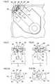
- FIGS. 4 to 7cover an embodiment specific to an optical disc reader of the portable type, the energy source of which must be saved.
- a shutter 52also covers, uncovers, the active element 30, a lens through which the light beam of the reading and / or recording device 31 which is a laser passes.
- the device 31is mobile for monitoring information and carries a coil 32 connected to two soft iron plates 33, 34 surrounding a rotor 36 permanently magnetized North, South on each half moon ( Figures 5A, 6A) and provided with 'an eccentric finger 38 which acts through a slot 50 (Fig. 5) on the shutter 52 to rotate it around the axis 54.
- the assembly of coil 32, plates 33, 34 and rotor 36constitutes a micro- stepper motor activated by a short current pulse which requires only a tiny expenditure of energy and ensures the plates 33, 34 always opposite polarities ( Figures 5A, 6A).
- the coil 32is advantageously supplied by a brief electric pulse (200 ms) of low voltage (3V.) The direction of which determines that of the current flowing through it, therefore the polarity of the plates 33, 34.
- the pulse of circuit 62is used (FIG. 7) ensuring that the reading device is switched on and off, recording 31 which is positive, respectively negative since each switches the polarities of the plates 33, 34, this which rotates the rotor 36 (arrow R) each time by half a turn.
- the finger 38can therefore pass at any time, for a positive pulse, from the position of FIG. 6A to that of FIG. 5A and through the slot 50, pivot the shutter 52 which uncovers the lens 30 (FIG. 5) and remains in this stable position. Reading and / or recording of information can take place.
- the brevity of the pulsedoes not at all require a permanent current source, so this protection means can be mounted in any vehicle device; in addition, very low energy is required, which allows it to be integrated into any portable device.
- each plate 33, 34advantageously has, near the rotor 36, a slight discontinuity 39 to concentrate the passage magnetic flux, always taking the shortest path, on sector 40 and therefore stop the rotor 36 in a position where the diameter separating its North and South poles is offset from the axis of the slot separating the plates 33, 34.
- the rotor 36always turns during the inversion of the polarities.
- the magnetic fields usedare very weak and the polarities of the plates 33, 34 and the rotor 36 being opposite and very close, there is no magnetic loss.
- this means of protectionis completely safe, there is no need to memorize the direction of the control pulse or the position of the shutter 52 in the event of a failure or change of supply because a positive pulse always makes rotate the shutter in one direction (uncover the lens), a negative pulse always makes it rotate in the other direction (cover the lens).
- the control pulsesbeing generated by switching on or off the reading and / or recording device 31, the lens 30 is only discovered in reading and / or recording mode, closed in any other fashion.
- This embodimentcan be applied to any head other than optical. It is also possible to use the pulses generated by the switch 60 or the transfer mechanism 61, when it exists.
Landscapes
- Physics & Mathematics (AREA)
- Optics & Photonics (AREA)
- Optical Head (AREA)
- Magnetic Heads (AREA)
Abstract
Description
Translated fromFrenchLa présente invention se rapporte aux dispositifs de lecture et/ou d'enregistrement tant par voie optique que magnétique,... d'informations tant analogiques que numériques, sur un support tel un disque, une bande, une carte, etc... et concerne des moyens assurant leur protection contre le dépôt de particules étrangères.The present invention relates to devices for reading and / or recording both optically and magnetically, ... both analog and digital information, on a medium such as a disc, tape, card, etc ... and relates to means ensuring their protection against the deposit of foreign particles.
Les améliorations constamment réalisées dans le domaine des supports d'informations et celui des dispositifs de lecture et d'enregistrement, communément appelés têtes, permettent de doubler la densité des informations environ tous les 3 ou 4 ans, donc de rendre les appareils plus compacts en mettant en oeuvre des têtes de plus en plus petites. De ce fait, les particules étrangères telles que poussières, impuretés, vapeurs, humidité dont la taille reste sensiblement la même, risquent, par dépôt sur ces têtes, d'en diminuer sensiblement les performances, voire de les obturer, ce qui occasionne des erreurs de lecture ou d'enregistrement d'informations.The improvements constantly made in the field of information carriers and that of reading and recording devices, commonly called heads, make it possible to double the density of information approximately every 3 or 4 years, therefore making the devices more compact by using increasingly smaller heads. As a result, foreign particles such as dust, impurities, vapors, humidity, the size of which remains substantially the same, risk, by deposition on these heads, of significantly reducing their performance, or even of plugging them, which causes errors. reading or recording information.
Pour remédier à ces problèmes, on a proposé des systèmes de nettoyage des têtes de lecture et/ou d'enregistrement, tel celui décrit dans le brevet américain 5.170.304, activés temporairement à la mise sous tension de l'appareil. Cependant ces systèmes sont peu satisfaisants car étant internes à l'appareil, leur remplacement ou entretien régulier est pratiquement impossible. En outre, ils n'empêchent pas le dépôt de particules.To remedy these problems, cleaning systems for reading and / or recording heads have been proposed, such as that described in US patent 5,170,304, temporarily activated when the device is switched on. However these systems are unsatisfactory because being internal to the device, their replacement or regular maintenance is practically impossible. In addition, they do not prevent the deposition of particles.
On a proposé, dans le brevet américain 4.519.059 de la demanderesse, des moyens masquant la tête optique mais ceci a lieu uniquement durant le nettoyage du support d'informations.In the applicant's patent 4,519,059, means have been proposed masking the optical head, but this only takes place during the cleaning of the information medium.
La demande japonaise 51-111500 propose un obturateur mû par un électro-aimant pour protéger le support d'informations d'une exposition prolongée à la lumière d'un laser en l'absence d'enregistrement. Un système similaire est décrit dans la demande japonaise 63-146235. Mais le montage d'un électro-aimant est très peu recommandable à proximité d'une tête optique ou magnétique à cause des champs magnétiques qu'il crée tandis qu'un blindage de la tête est irréaliste car onéreux et alourdirait l'équipage mobile qui doit rester le plus léger possible. De plus, ces obturateurs n'ont pas de position stable lors de la lecture et/ou l'enregistrement, ce qui nécessite d'alimenter en permanence l'électro-aimant.Japanese application 51-111500 proposes a shutter driven by an electromagnet to protect the information medium from prolonged exposure to the light of a laser in the absence of recording. A similar system is described in Japanese application 63-146235. However, mounting an electromagnet is highly ill-advised near an optical or magnetic head because of the magnetic fields which it creates while shielding the head is unrealistic because it is expensive and would weigh down the mobile equipment which should be kept as light as possible. In addition, these shutters do not have a stable position during reading and / or recording, which requires the permanent supply of the electromagnet.
La demande de brevet allemand DE 195 23 785, le brevet américain 5.297.122 proposent des systèmes mécaniques masquant les têtes de lecture mais ils sont encombrants et nécessitent pour leur actionnement respectivement le retour des têtes à une position déterminée (le sillon initial du disque), l'éjection du support d'informations ce qui est très peu souple et interdit toute reprise instantanée de la lecture ou de l'enregistrement à l'endroit de son interruption. En outre, l'éjection du support ou retour de la tête à une position déterminée ne peut être assuré pour des appareils montés dans des véhicules car la clé de contact, en coupant instantanément l'alimentation, interdit tout mouvement.The German patent application DE 195 23 785, the American patent 5,297,122 propose mechanical systems masking the read heads but they are bulky and require for their actuation respectively the return of the heads to a determined position (the initial groove of the disc) , ejecting the information medium which is very inflexible and prohibits any instant resumption of reading or recording at the place of its interruption. In addition, the ejection of the support or return of the head to a determined position can not be ensured for devices mounted in vehicles because the ignition key, by instantly cutting off the power, prevents any movement.
Le but de la présente invention est donc de remédier aux inconvénients précités en proposant des moyens de protection simples, efficaces, actionnables à tout moment et ne nécessitant pas l'accomplissement préalable d'une phase particulière.The object of the present invention is therefore to remedy the aforementioned drawbacks by proposing simple, effective means of protection, operable at any time and not requiring the prior accomplishment of a particular phase.
Un second but est de proposer des moyens permettant de reprendre la lecture et/ou l'enregistrement d'informations pratiquement instantanément à l'endroit où elle a été interrompue, et ce, dès le rétablissement de l'opération ou de l'alimentation.A second aim is to propose means making it possible to resume reading and / or recording of information practically instantaneously at the place where it has been interrupted, and this, as soon as the operation or feeding is restored.
Un autre but de la présente invention est de proposer des moyens peu coûteux pour ne pas grever le prix des appareils auxquels ils sont incorporés.Another object of the present invention is to provide inexpensive means so as not to burden the price of the devices in which they are incorporated.
Un autre but de l'invention est de proposer des moyens aisément adaptables à tout type d'appareil : pour maisons, voitures, portables, portatifs....Another object of the invention is to provide means that are easily adaptable to any type of device: for homes, cars, portable, portable, etc.
Un autre but de l'invention est de proposer des moyens nécessitant très peu d'énergie pour épargner la source d'énergie (piles, accumulateurs,...) des appareils portables, portatifs.Another object of the invention is to propose means requiring very little energy to save the energy source (batteries, accumulators, etc.) of portable and portable devices.
Un autre but est de proposer des moyens très stables tant en position active qu'inactive.Another aim is to offer very stable means both in active and inactive positions.
En vue de la réalisation de ces buts, les moyens objets de la présente invention sont essentiellement caractérisés par le contenu de la revendication principale.With a view to achieving these aims, the means which are the subject of the present invention are essentially characterized by the content of the main claim.
Divers avantages, caractéristiques, particularités, ressortiront de la description détaillée, donnée ci-dessous à titre non limitatif, de deux modes de réalisation préférés auxquels des améliorations peuvent être apportées sans pour autant sortir du cadre de l'invention et pour lesquels :
- la figure 1 est une vue de face d'un premier mode de réalisation, les moyens de protection étant en position inactive,
- la figure 2 est une vue de côté des éléments apparaissant à la figure 1,
- la figure 3 est une vue de dessus des éléments de la figure 1, les moyens de protection étant actifs,
- la figure 4 est une vue de dessus partielle d'un second mode de réalisation, les moyens de protection étant inactifs,
- la figure 5 est une vue de détail à plus grande échelle d'éléments de la figure 4,
- la figure 6 est semblable à la figure 5, les moyens de protection étant actifs,
- les figures 5A et 6A représentent un détail particulier des figures 5 et 6 à plus grande échelle.
- la figure 7 est un diagramme électrique schématique d'un appareil équipé des moyens de protection.
- FIG. 1 is a front view of a first embodiment, the protection means being in the inactive position,
- Figure 2 is a side view of the elements appearing in Figure 1,
- FIG. 3 is a top view of the elements of FIG. 1, the protection means being active,
- FIG. 4 is a partial top view of a second embodiment, the protection means being inactive,
- FIG. 5 is an enlarged detail view of the elements of FIG. 4,
- FIG. 6 is similar to FIG. 5, the protection means being active,
- Figures 5A and 6A show a particular detail of Figures 5 and 6 on a larger scale.
- Figure 7 is a schematic electrical diagram of a device equipped with protection means.
Les figures 1 à 3 et 7 concernent un appareil à cassettes tel que décrit dans les brevets belges 891.045 et 94 00149 de la demanderesse où la lecture/ l'enregistrement d'informations se fait après application de la tête magnétique sur le support qui est une bande magnétique.Figures 1 to 3 and 7 relate to a cassette device as described in Belgian patents 891,045 and 94 00,149 of the applicant where the reading / recording of information is done after application of the magnetic head on the support which is a magnetic tape.
Comme le montrent ces figures, un montant latéral fixe 2 de l'appareil situé à proximité de la tête magnétique 20 supporte une glissière 4 du mécanisme de transfert (non représenté) assurant le mouvement relatif entre la tête 20 et le support d'informations pour leur mise en position opérative, respectivement inopérative. Cette glissière 4 est translatée (flèches F, G) pour guider un téton 6 du logement recevant la cassette par déplacement simultané au travers de la fente 3 en forme de L pratiquée dans le montant 2 et la fente inclinée 7 de la glissière 4.As these figures show, a fixed lateral upright 2 of the device located near the
Conformément à l'invention, une coulisse 10 munie de deux fentes horizontales 11 laissant passer deux tétons 12, 13 fixés sur la glissière 4, s'appuie sur et est guidée par la surface externe de ladite glissière 4 ; un pli 14 formé sur son bord gauche sert d'ancrage à un ressort 17 dont l'autre extrémité est fixée au téton 13, tandis que sur son bord droit la coulisse 10 porte à l'aide d'une lamelle flexible 18 un obturateur 16 ayant sensiblement la taille de l'élément actif 22 de la tête 20. Cette lamelle 18 est de préférence élastique pour maintenir en position opérative l'obturateur 16 contre la tête 20.According to the invention, a
En l'absence de cassette ou lorsque l'appareil est inopératif, tous les éléments précités sont dans la position représentée à la figure 3, la tête 20 est écartée du support magnétique tandis que les tétons 12, 13 et le ressort 17 maintiennent de façon stable la coulisse 10 à l'encontre de tout déplacement, l'obturateur 16 recouvrant l'élément actif 22 pour y éviter tout dépôt de poussière, particule, ou même vapeur, fumée ou humidité.In the absence of a cassette or when the device is inoperative, all the aforementioned elements are in the position shown in FIG. 3, the
Lorsque l'appareil est rendu opératif par actionnement soit de son interrupteur général 60 (figure 7) soit du mécanisme de transfert 61 suite à l'introduction d'une cassette, la glissière 4 est, d'une manière non représentée car bien connue, translatée (flèche F - figure 3). Dès lors, les tétons 12, 13 parcourent les fentes 11 libérant la coulisse 10 à l'action du ressort 17 qui l'entraîne dans le même sens et aboutissent à l'extrémité droite desdites fentes 11. Ainsi, l'obturateur 16 est dégagé de l'élément actif 22 de la tête 20, amené et maintenu dans la position stable représentée à la figure 1; une butée 19 fixée au montant 2 en limitant le déplacement vers la droite. L'élément actif 22 étant exposé, la tête 20 est déplacée (flèche H - figure 2) pour être appliquée sur le support d'informations.When the device is made operational by actuating either its general switch 60 (FIG. 7) or the
Lorsque l'appareil est commuté en mode inopératif par actionnement de l'interrupteur 60 ou du mécanisme de transfert 61, la tête 20 est dégagée du support d'informations, simultanément la glissière 4 est déplacée en sens inverse (flèche G - figure 1), ainsi les tétons 12, 13 parviennent à l'extrémité gauche des fentes 11 puis déplacent la coulisse 10 qui ramène l'obturateur 16 contre l'élément actif 22 (figure 3) et l'y maintient grâce à la lamelle flexible 18.When the device is switched to inoperative mode by actuation of the
L'élément actif 22 est donc protégé en permanence de tout dépôt, contamination par soit le support d'informations en mode de lecture et/ou d'enregistrement, soit l'obturateur 16 dans tout autre mode. L'obturateur 16 muni d'une matière appropriée, en étant translaté sur l'élément actif 22, peut avantageusement assurer son nettoyage.The
Les figures 4 à 7 couvrent une réalisation propre à un lecteur de disque optique du type portatif dont la source d'énergie doit être impérativement épargnée. Un obturateur 52 vient également recouvrir, découvrir l'élément actif 30, une lentille par laquelle passe le faisceau lumineux du dispositif de lecture et/ou d'enregistrement 31 qui est un laser.FIGS. 4 to 7 cover an embodiment specific to an optical disc reader of the portable type, the energy source of which must be saved. A
Le dispositif 31 est mobile pour assurer le suivi des informations et porte une bobine 32 reliée à deux plaques en fer doux 33, 34 entourant un rotor 36 aimanté en permanence Nord, Sud sur chaque demi-lune (figures 5A, 6A) et muni d'un doigt 38 excentré qui agit grâce à une fente 50 (Fig. 5) sur l'obturateur 52 pour le faire pivoter autour de l'axe 54. L'ensemble bobine 32, plaques 33, 34 et rotor 36 constitue un micro-moteur pas-à-pas activé par une brève impulsion de courant ce qui ne nécessite qu'une infime dépense d'énergie et assure aux plaques 33, 34 des polarités toujours opposées (figures 5A, 6A). En l'absence d'impulsion, le fer doux des plaques 33, 34 assure la rémanence de leurs polarités, ce qui contrecarre toute rotation éventuelle du rotor 36 suite à des chocs ou vibrations et lui confère donc deux positions excessivement stables où la lentille 30 est découverte, respectivement recouverte (figures 5, 6).The
Pour déplacer l'obturateur 52, la bobine 32 est avantageusement alimentée par une brève impulsion électrique (200 ms) de faible tension (3V.) dont le sens détermine celui du courant la parcourant, donc la polarité des plaques 33, 34. Dans un mode de réalisation préféré, on utilise l'impulsion du circuit 62 (figure 7) assurant la mise sous tension, hors tension du dispositif de lecture, enregistrement 31 qui est positive, respectivement négative car chacune commute les polarités des plaques 33, 34, ce qui fait tourner le rotor 36 (flèche R) à chaque fois d'un demi tour. Le doigt 38 peut donc passer à tout moment, pour une impulsion positive, de la position de la figure 6A à celle de la figure 5A et par la fente 50, pivoter l'obturateur 52 qui découvre la lentille 30 (figure 5) et reste dans cette position stable. La lecture et/ou l'enregistrement d'informations peut avoir lieu.To move the
Pour recouvrir la lentille 30 à tout moment, il suffit d'utiliser l'impulsion négative assurant la mise hors tension du dispositif 31; le courant circule dans la bobine 32 en sens opposé, créant sur les plaques 33, 34 des polarités opposées aux précédentes (figure 6A) qui font pivoter le rotor 36 et son doigt 38 d'un demi tour amenant l'obturateur 52 dans la position stable de la figure 6.To cover the
La brièveté de l'impulsion ne nécessite nullement une source de courant permanent, donc ce moyen de protection peut être monté dans tout appareil pour véhicule ; en outre, une très faible énergie est requise, ce qui permet de l'intégrer à tout appareil portatif.The brevity of the pulse does not at all require a permanent current source, so this protection means can be mounted in any vehicle device; in addition, very low energy is required, which allows it to be integrated into any portable device.
Comme montré aux figures 5A, 6A, chaque plaque 33, 34 possède avantageusement à proximité du rotor 36 une légère discontinuité 39 pour concentrer le passage du flux magnétique, empruntant toujours le chemin le plus court, sur le secteur 40 et donc stopper le rotor 36 dans une position où le diamètre séparant ses pôles Nord et Sud est décalé de l'axe de la fente séparant les plaques 33, 34. Ainsi, le rotor 36 tourne toujours lors de l'inversion des polarités.As shown in FIGS. 5A, 6A, each
Les champs magnétiques mis en oeuvre sont très faibles et les polarités des plaques 33, 34 et du rotor 36 étant opposées et très proches, il n'y a aucune perte magnétique.The magnetic fields used are very weak and the polarities of the
De plus, ce moyen de protection est d'une sécurité totale, il est inutile de mémoriser le sens de l'impulsion de commande ou la position de l'obturateur 52 en cas de panne ou changement d'alimentation car une impulsion positive fait toujours pivoter l'obturateur dans un sens (découvrir la lentille), une impulsion négative le fait toujours pivoter dans l'autre sens (recouvrir la lentille). Les impulsions de commande étant générées par la mise sous tension ou hors tension du dispositif de lecture et/ou d'enregistrement 31, la lentille 30 n'est découverte qu'en mode de lecture et/ou d'enregistrement, obturée dans tout autre mode. Ce mode de réalisation peut être appliqué à toute tête autre qu'optique. Il est aussi possible d'utiliser les impulsions générées par l'interrupteur 60 ou le mécanisme de transfert 61, lorsqu'il existe.In addition, this means of protection is completely safe, there is no need to memorize the direction of the control pulse or the position of the
A la place d'un rotor aimanté 36, on peut appliquer sur la face inférieure de l'obturateur 52 proche des plaques 33, 34, une matière magnétique telle qu'employée dans les afficheurs Signalex, l'obturateur étant alors attiré par un pôle magnétique, repoussé par l'autre, tandis que l'inversion de polarité des plaques 33, 34 assure son pivotement.
- 2
- montant
- 3
- fente en L
- 4
- glissière
- 6
- téton
- 7
- fente inclinée
- 10
- coulisse
- 11
- fentes de 10
- 12, 13
- tétons
- 14
- pli
- 16
- obturateur
- 17
- ressort de traction
- 18
- lamelle flexible
- 19
- butée
- 20
- tête magnétique
- 22
- élément actif de 20
- 30
- élément actif de 31, lentille
- 31
- dispositif de lecture/enregistrement
- 32
- bobines
- 33, 34
- plaques
- 36
- rotor aimanté
- 38
- doigt
- 39
- discontinuité
- 40
- secteur
- 50
- fente
- 52
- obturateur
- 54
- axe
- 60
- interrupteur Marche/arrêt
- 61
- mécanisme de transfert
- 62
- circuit
- 2
- amount
- 3
- L-shaped slot
- 4
- slide
- 6
- nipple
- 7
- angled slot
- 10
- backstage
- 11
- 10 slots
- 12, 13
- nipples
- 14
- fold
- 16
- shutter
- 17
- tension spring
- 18
- flexible coverslip
- 19
- stop
- 20
- magnetic head
- 22
- active element of 20
- 30
- active element of 31, lens
- 31
- playback / recording device
- 32
- coils
- 33, 34
- plates
- 36
- magnetic rotor
- 38
- finger
- 39
- discontinuity
- 40
- sector
- 50
- slot
- 52
- shutter
- 54
- axis
- 60
- on / off switch
- 61
- transfer mechanism
- 62
- circuit
Claims (10)
Translated fromFrenchApplications Claiming Priority (2)
| Application Number | Priority Date | Filing Date | Title |
|---|---|---|---|
| BE9600442ABE1010187A3 (en) | 1996-05-15 | 1996-05-15 | Protection device for ways to play and / or recording. |
| BE9600442 | 1996-05-15 |
Publications (2)
| Publication Number | Publication Date |
|---|---|
| EP0807934A1true EP0807934A1 (en) | 1997-11-19 |
| EP0807934B1 EP0807934B1 (en) | 2007-02-21 |
Family
ID=3889754
Family Applications (1)
| Application Number | Title | Priority Date | Filing Date |
|---|---|---|---|
| EP97870066AExpired - LifetimeEP0807934B1 (en) | 1996-05-15 | 1997-05-07 | Means for protecting reading and/or writing device |
Country Status (5)
| Country | Link |
|---|---|
| US (1) | US5946291A (en) |
| EP (1) | EP0807934B1 (en) |
| JP (1) | JPH10124816A (en) |
| BE (1) | BE1010187A3 (en) |
| DE (1) | DE69737380T2 (en) |
Cited By (1)
| Publication number | Priority date | Publication date | Assignee | Title |
|---|---|---|---|---|
| WO2002050825A1 (en)* | 2000-12-20 | 2002-06-27 | Thomson Licensing S.A. | Recording and/or reproducing apparatus for optical recording media |
Families Citing this family (4)
| Publication number | Priority date | Publication date | Assignee | Title |
|---|---|---|---|---|
| US6385161B1 (en)* | 1999-07-14 | 2002-05-07 | Hewlett-Packard Company | Securing mechanism and method for an optical disc drive |
| US6487158B2 (en) | 1999-07-14 | 2002-11-26 | Hewlett-Packard Company | Cover member and method for an optical disc drive |
| KR100536691B1 (en)* | 2003-05-31 | 2005-12-14 | 주식회사 대우일렉트로닉스 | Holographic rom system |
| TWI364755B (en)* | 2008-09-23 | 2012-05-21 | Quanta Storage Inc | Protection cover of pick-up head |
Citations (10)
| Publication number | Priority date | Publication date | Assignee | Title |
|---|---|---|---|---|
| JPS5622228A (en)* | 1979-07-30 | 1981-03-02 | Matsushita Electric Ind Co Ltd | Dust protector of optical recording and reproducing device |
| JPS61237236A (en)* | 1985-04-15 | 1986-10-22 | Canon Inc | Objective lens cleaning mechanism for optical information recording and reproducing equipment |
| JPS61280043A (en)* | 1985-06-05 | 1986-12-10 | Nec Eng Ltd | Optical disk device |
| JPS63146235A (en)* | 1986-12-09 | 1988-06-18 | Canon Inc | Optical information recording and reproducing device |
| JPS63244467A (en)* | 1987-03-31 | 1988-10-11 | Toshiba Corp | information processing equipment |
| JPS63244477A (en)* | 1987-03-31 | 1988-10-11 | Toshiba Corp | information processing equipment |
| JPS63255839A (en)* | 1987-04-13 | 1988-10-24 | Matsushita Graphic Commun Syst Inc | Optical disk recording and reproducing device |
| JPH05144058A (en)* | 1991-11-20 | 1993-06-11 | Hitachi Ltd | Lens cleaner |
| US5268890A (en)* | 1993-02-09 | 1993-12-07 | Delco Electronics Corporation | Self-cleaning optical disc system |
| US5297122A (en)* | 1992-09-14 | 1994-03-22 | Hewlett-Packard Company | Dust protection assembly for magneto-optic drive apparatus |
Family Cites Families (7)
| Publication number | Priority date | Publication date | Assignee | Title |
|---|---|---|---|---|
| JPS5922293B2 (en)* | 1976-09-16 | 1984-05-25 | 三菱電機株式会社 | information recording device |
| BE896473A (en)* | 1983-04-15 | 1983-08-01 | Staar Sa | DEVICE FOR CLEANING DISCS IN A RECORDER, |
| DE3840311A1 (en)* | 1988-11-30 | 1990-05-31 | Thomson Brandt Gmbh | OPTICAL RECORDING AND / OR PLAYBACK DEVICE |
| JPH03134815A (en)* | 1989-10-20 | 1991-06-07 | Hitachi Ltd | Cleaning device control method for magnetic recording and reproducing device |
| JPH04330693A (en)* | 1991-04-30 | 1992-11-18 | Kyocera Corp | objective lens actuator |
| JP3320906B2 (en)* | 1994-06-30 | 2002-09-03 | アルパイン株式会社 | Disk unit |
| JP3462293B2 (en)* | 1995-04-14 | 2003-11-05 | 株式会社東芝 | Optical disk drive |
- 1996
- 1996-05-15BEBE9600442Apatent/BE1010187A3/ennot_activeIP Right Cessation
- 1997
- 1997-04-01USUS08/831,513patent/US5946291A/ennot_activeExpired - Fee Related
- 1997-05-07DEDE69737380Tpatent/DE69737380T2/ennot_activeExpired - Fee Related
- 1997-05-07EPEP97870066Apatent/EP0807934B1/ennot_activeExpired - Lifetime
- 1997-05-14JPJP9137937Apatent/JPH10124816A/enactivePending
Patent Citations (10)
| Publication number | Priority date | Publication date | Assignee | Title |
|---|---|---|---|---|
| JPS5622228A (en)* | 1979-07-30 | 1981-03-02 | Matsushita Electric Ind Co Ltd | Dust protector of optical recording and reproducing device |
| JPS61237236A (en)* | 1985-04-15 | 1986-10-22 | Canon Inc | Objective lens cleaning mechanism for optical information recording and reproducing equipment |
| JPS61280043A (en)* | 1985-06-05 | 1986-12-10 | Nec Eng Ltd | Optical disk device |
| JPS63146235A (en)* | 1986-12-09 | 1988-06-18 | Canon Inc | Optical information recording and reproducing device |
| JPS63244467A (en)* | 1987-03-31 | 1988-10-11 | Toshiba Corp | information processing equipment |
| JPS63244477A (en)* | 1987-03-31 | 1988-10-11 | Toshiba Corp | information processing equipment |
| JPS63255839A (en)* | 1987-04-13 | 1988-10-24 | Matsushita Graphic Commun Syst Inc | Optical disk recording and reproducing device |
| JPH05144058A (en)* | 1991-11-20 | 1993-06-11 | Hitachi Ltd | Lens cleaner |
| US5297122A (en)* | 1992-09-14 | 1994-03-22 | Hewlett-Packard Company | Dust protection assembly for magneto-optic drive apparatus |
| US5268890A (en)* | 1993-02-09 | 1993-12-07 | Delco Electronics Corporation | Self-cleaning optical disc system |
Non-Patent Citations (7)
| Title |
|---|
| PATENT ABSTRACTS OF JAPAN vol. 005, no. 073 (P - 061) 15 May 1981 (1981-05-15)* |
| PATENT ABSTRACTS OF JAPAN vol. 011, no. 084 (P - 556) 13 March 1987 (1987-03-13)* |
| PATENT ABSTRACTS OF JAPAN vol. 011, no. 144 (P - 574) 12 May 1987 (1987-05-12)* |
| PATENT ABSTRACTS OF JAPAN vol. 012, no. 408 (P - 778) 28 October 1988 (1988-10-28)* |
| PATENT ABSTRACTS OF JAPAN vol. 013, no. 054 (P - 824) 8 February 1989 (1989-02-08)* |
| PATENT ABSTRACTS OF JAPAN vol. 013, no. 070 (P - 829) 17 February 1989 (1989-02-17)* |
| PATENT ABSTRACTS OF JAPAN vol. 017, no. 536 (P - 1620) 27 September 1993 (1993-09-27)* |
Cited By (2)
| Publication number | Priority date | Publication date | Assignee | Title |
|---|---|---|---|---|
| WO2002050825A1 (en)* | 2000-12-20 | 2002-06-27 | Thomson Licensing S.A. | Recording and/or reproducing apparatus for optical recording media |
| US7007288B2 (en) | 2000-12-20 | 2006-02-28 | Thomson Licensing | Recording and/or reproducing apparatus for optical recording media |
Also Published As
| Publication number | Publication date |
|---|---|
| BE1010187A3 (en) | 1998-02-03 |
| DE69737380D1 (en) | 2007-04-05 |
| JPH10124816A (en) | 1998-05-15 |
| EP0807934B1 (en) | 2007-02-21 |
| US5946291A (en) | 1999-08-31 |
| DE69737380T2 (en) | 2007-11-29 |
Similar Documents
| Publication | Publication Date | Title |
|---|---|---|
| WO2009109449A1 (en) | Power generation device with two mobile parts | |
| FR2504718A1 (en) | SELF-MAINTAINED SOLENOID | |
| FR2621170A1 (en) | BREAKER-LIMIT | |
| JPH02214076A (en) | Device for holding recovery of actuator of disk device | |
| FR2777079A1 (en) | DEVICE FOR DETECTING THE OPENING OF A COUNTER | |
| EP0807934B1 (en) | Means for protecting reading and/or writing device | |
| FR2539543A1 (en) | LOCKING DEVICE FOR TURNKEY APPARATUS | |
| FR2680920A1 (en) | Electric motor with a device for detecting the position of the rotor, the speed of rotation and/or the direction of rotation | |
| JP4164378B2 (en) | Light control device | |
| EP0824289B1 (en) | Electromechanical transducer featuring two permanent magnet rotors | |
| EP2085987B1 (en) | Dual-actuation-mode control device | |
| FR2514928A1 (en) | OPERATING MODE CHANGING DEVICE FOR MAGNETIC TAPE RECORDER | |
| FR2532459A1 (en) | DEVICE FOR AUTOMATIC CLEANING OF A CASSETTE RECORDER RECEIVER READING HEAD | |
| EP0163570B1 (en) | Segment display system, particularly for use in a remotely controlled numerical display | |
| EP1792326B1 (en) | Bistable electromagnetic actuator with integrated lock | |
| FR2557343A1 (en) | DEVICE FOR CLEANING A RECORDING AND READING APPARATUS SUCH AS A MAGNETOSCOPE | |
| FR2586129A1 (en) | Optical fibres signalling and display device | |
| FR2537760A1 (en) | NEEDLE PROTECTION MECHANISM FOR A VIDEO DRIVE | |
| EP3018690B1 (en) | Electromagnetic actuator and electric contactor including such an actuator | |
| EP0509391A1 (en) | Protection system for electric circuits | |
| CH607307A5 (en) | Highly sensitive electromagnetic relay | |
| BE657828A (en) | ||
| FR2666927A1 (en) | Electromagnetic relay | |
| WO2006005817A1 (en) | Circuit breaker comprising a bistable actuator and safety device equipped with said circuit breaker | |
| FR2808616A1 (en) | ROTARY ELECTROMAGNET |
Legal Events
| Date | Code | Title | Description |
|---|---|---|---|
| PUAI | Public reference made under article 153(3) epc to a published international application that has entered the european phase | Free format text:ORIGINAL CODE: 0009012 | |
| AK | Designated contracting states | Kind code of ref document:A1 Designated state(s):BE CH DE FR GB IT LI NL PT | |
| 17P | Request for examination filed | Effective date:19971216 | |
| GRAP | Despatch of communication of intention to grant a patent | Free format text:ORIGINAL CODE: EPIDOSNIGR1 | |
| GRAS | Grant fee paid | Free format text:ORIGINAL CODE: EPIDOSNIGR3 | |
| GRAA | (expected) grant | Free format text:ORIGINAL CODE: 0009210 | |
| AK | Designated contracting states | Kind code of ref document:B1 Designated state(s):BE CH DE FR GB IT LI NL PT | |
| REG | Reference to a national code | Ref country code:GB Ref legal event code:FG4D Free format text:NOT ENGLISH | |
| REG | Reference to a national code | Ref country code:CH Ref legal event code:EP | |
| GBT | Gb: translation of ep patent filed (gb section 77(6)(a)/1977) | Effective date:20070305 | |
| REG | Reference to a national code | Ref country code:CH Ref legal event code:NV Representative=s name:BUGNION S.A. | |
| REF | Corresponds to: | Ref document number:69737380 Country of ref document:DE Date of ref document:20070405 Kind code of ref document:P | |
| PG25 | Lapsed in a contracting state [announced via postgrant information from national office to epo] | Ref country code:PT Free format text:LAPSE BECAUSE OF FAILURE TO SUBMIT A TRANSLATION OF THE DESCRIPTION OR TO PAY THE FEE WITHIN THE PRESCRIBED TIME-LIMIT Effective date:20070723 | |
| PLBE | No opposition filed within time limit | Free format text:ORIGINAL CODE: 0009261 | |
| 26N | No opposition filed | Effective date:20071122 | |
| PG25 | Lapsed in a contracting state [announced via postgrant information from national office to epo] | Ref country code:IT Free format text:LAPSE BECAUSE OF FAILURE TO SUBMIT A TRANSLATION OF THE DESCRIPTION OR TO PAY THE FEE WITHIN THE PRESCRIBED TIME-LIMIT Effective date:20070221 | |
| PGFP | Annual fee paid to national office [announced via postgrant information from national office to epo] | Ref country code:DE Payment date:20090527 Year of fee payment:13 | |
| PGFP | Annual fee paid to national office [announced via postgrant information from national office to epo] | Ref country code:GB Payment date:20090522 Year of fee payment:13 | |
| PGFP | Annual fee paid to national office [announced via postgrant information from national office to epo] | Ref country code:FR Payment date:20100602 Year of fee payment:14 | |
| PGFP | Annual fee paid to national office [announced via postgrant information from national office to epo] | Ref country code:NL Payment date:20100527 Year of fee payment:14 | |
| PGFP | Annual fee paid to national office [announced via postgrant information from national office to epo] | Ref country code:CH Payment date:20100527 Year of fee payment:14 Ref country code:BE Payment date:20100526 Year of fee payment:14 | |
| GBPC | Gb: european patent ceased through non-payment of renewal fee | Effective date:20100507 | |
| PG25 | Lapsed in a contracting state [announced via postgrant information from national office to epo] | Ref country code:DE Free format text:LAPSE BECAUSE OF NON-PAYMENT OF DUE FEES Effective date:20101201 | |
| PG25 | Lapsed in a contracting state [announced via postgrant information from national office to epo] | Ref country code:GB Free format text:LAPSE BECAUSE OF NON-PAYMENT OF DUE FEES Effective date:20100507 | |
| BERE | Be: lapsed | Owner name:STAAR S.A. Effective date:20110531 | |
| REG | Reference to a national code | Ref country code:NL Ref legal event code:V1 Effective date:20111201 | |
| REG | Reference to a national code | Ref country code:CH Ref legal event code:PL | |
| PG25 | Lapsed in a contracting state [announced via postgrant information from national office to epo] | Ref country code:NL Free format text:LAPSE BECAUSE OF NON-PAYMENT OF DUE FEES Effective date:20111201 Ref country code:CH Free format text:LAPSE BECAUSE OF NON-PAYMENT OF DUE FEES Effective date:20110531 Ref country code:LI Free format text:LAPSE BECAUSE OF NON-PAYMENT OF DUE FEES Effective date:20110531 | |
| REG | Reference to a national code | Ref country code:FR Ref legal event code:ST Effective date:20120131 | |
| PG25 | Lapsed in a contracting state [announced via postgrant information from national office to epo] | Ref country code:BE Free format text:LAPSE BECAUSE OF NON-PAYMENT OF DUE FEES Effective date:20110531 | |
| PG25 | Lapsed in a contracting state [announced via postgrant information from national office to epo] | Ref country code:FR Free format text:LAPSE BECAUSE OF NON-PAYMENT OF DUE FEES Effective date:20110531 |