EP0806920B1 - Joint prosthesis - Google Patents
Joint prosthesisDownload PDFInfo
- Publication number
- EP0806920B1 EP0806920B1EP96903803AEP96903803AEP0806920B1EP 0806920 B1EP0806920 B1EP 0806920B1EP 96903803 AEP96903803 AEP 96903803AEP 96903803 AEP96903803 AEP 96903803AEP 0806920 B1EP0806920 B1EP 0806920B1
- Authority
- EP
- European Patent Office
- Prior art keywords
- femoral
- component
- condyles
- condyle
- knee
- Prior art date
- Legal status (The legal status is an assumption and is not a legal conclusion. Google has not performed a legal analysis and makes no representation as to the accuracy of the status listed.)
- Expired - Lifetime
Links
Images

Classifications
- A—HUMAN NECESSITIES
- A61—MEDICAL OR VETERINARY SCIENCE; HYGIENE
- A61F—FILTERS IMPLANTABLE INTO BLOOD VESSELS; PROSTHESES; DEVICES PROVIDING PATENCY TO, OR PREVENTING COLLAPSING OF, TUBULAR STRUCTURES OF THE BODY, e.g. STENTS; ORTHOPAEDIC, NURSING OR CONTRACEPTIVE DEVICES; FOMENTATION; TREATMENT OR PROTECTION OF EYES OR EARS; BANDAGES, DRESSINGS OR ABSORBENT PADS; FIRST-AID KITS
- A61F2/00—Filters implantable into blood vessels; Prostheses, i.e. artificial substitutes or replacements for parts of the body; Appliances for connecting them with the body; Devices providing patency to, or preventing collapsing of, tubular structures of the body, e.g. stents
- A61F2/02—Prostheses implantable into the body
- A61F2/30—Joints
- A61F2/38—Joints for elbows or knees
- A61F2/3886—Joints for elbows or knees for stabilising knees against anterior or lateral dislocations
- A—HUMAN NECESSITIES
- A61—MEDICAL OR VETERINARY SCIENCE; HYGIENE
- A61F—FILTERS IMPLANTABLE INTO BLOOD VESSELS; PROSTHESES; DEVICES PROVIDING PATENCY TO, OR PREVENTING COLLAPSING OF, TUBULAR STRUCTURES OF THE BODY, e.g. STENTS; ORTHOPAEDIC, NURSING OR CONTRACEPTIVE DEVICES; FOMENTATION; TREATMENT OR PROTECTION OF EYES OR EARS; BANDAGES, DRESSINGS OR ABSORBENT PADS; FIRST-AID KITS
- A61F2/00—Filters implantable into blood vessels; Prostheses, i.e. artificial substitutes or replacements for parts of the body; Appliances for connecting them with the body; Devices providing patency to, or preventing collapsing of, tubular structures of the body, e.g. stents
- A61F2/02—Prostheses implantable into the body
- A61F2/30—Joints
- A61F2/30767—Special external or bone-contacting surface, e.g. coating for improving bone ingrowth
- A61F2/30771—Special external or bone-contacting surface, e.g. coating for improving bone ingrowth applied in original prostheses, e.g. holes or grooves
- A61F2002/3082—Grooves
- A61F2002/30823—Grooves having the shape of a reverse dovetail
- A—HUMAN NECESSITIES
- A61—MEDICAL OR VETERINARY SCIENCE; HYGIENE
- A61F—FILTERS IMPLANTABLE INTO BLOOD VESSELS; PROSTHESES; DEVICES PROVIDING PATENCY TO, OR PREVENTING COLLAPSING OF, TUBULAR STRUCTURES OF THE BODY, e.g. STENTS; ORTHOPAEDIC, NURSING OR CONTRACEPTIVE DEVICES; FOMENTATION; TREATMENT OR PROTECTION OF EYES OR EARS; BANDAGES, DRESSINGS OR ABSORBENT PADS; FIRST-AID KITS
- A61F2/00—Filters implantable into blood vessels; Prostheses, i.e. artificial substitutes or replacements for parts of the body; Appliances for connecting them with the body; Devices providing patency to, or preventing collapsing of, tubular structures of the body, e.g. stents
- A61F2/02—Prostheses implantable into the body
- A61F2/30—Joints
- A61F2/30767—Special external or bone-contacting surface, e.g. coating for improving bone ingrowth
- A61F2/30771—Special external or bone-contacting surface, e.g. coating for improving bone ingrowth applied in original prostheses, e.g. holes or grooves
- A61F2002/30878—Special external or bone-contacting surface, e.g. coating for improving bone ingrowth applied in original prostheses, e.g. holes or grooves with non-sharp protrusions, for instance contacting the bone for anchoring, e.g. keels, pegs, pins, posts, shanks, stems, struts
- A61F2002/30879—Ribs
- A—HUMAN NECESSITIES
- A61—MEDICAL OR VETERINARY SCIENCE; HYGIENE
- A61F—FILTERS IMPLANTABLE INTO BLOOD VESSELS; PROSTHESES; DEVICES PROVIDING PATENCY TO, OR PREVENTING COLLAPSING OF, TUBULAR STRUCTURES OF THE BODY, e.g. STENTS; ORTHOPAEDIC, NURSING OR CONTRACEPTIVE DEVICES; FOMENTATION; TREATMENT OR PROTECTION OF EYES OR EARS; BANDAGES, DRESSINGS OR ABSORBENT PADS; FIRST-AID KITS
- A61F2/00—Filters implantable into blood vessels; Prostheses, i.e. artificial substitutes or replacements for parts of the body; Appliances for connecting them with the body; Devices providing patency to, or preventing collapsing of, tubular structures of the body, e.g. stents
- A61F2/02—Prostheses implantable into the body
- A61F2/30—Joints
- A61F2/46—Special tools for implanting artificial joints
- A61F2002/4631—Special tools for implanting artificial joints the prosthesis being specially adapted for being cemented
- A—HUMAN NECESSITIES
- A61—MEDICAL OR VETERINARY SCIENCE; HYGIENE
- A61F—FILTERS IMPLANTABLE INTO BLOOD VESSELS; PROSTHESES; DEVICES PROVIDING PATENCY TO, OR PREVENTING COLLAPSING OF, TUBULAR STRUCTURES OF THE BODY, e.g. STENTS; ORTHOPAEDIC, NURSING OR CONTRACEPTIVE DEVICES; FOMENTATION; TREATMENT OR PROTECTION OF EYES OR EARS; BANDAGES, DRESSINGS OR ABSORBENT PADS; FIRST-AID KITS
- A61F2310/00—Prostheses classified in A61F2/28 or A61F2/30 - A61F2/44 being constructed from or coated with a particular material
- A61F2310/00005—The prosthesis being constructed from a particular material
- A61F2310/00011—Metals or alloys
- A61F2310/00017—Iron- or Fe-based alloys, e.g. stainless steel
- A—HUMAN NECESSITIES
- A61—MEDICAL OR VETERINARY SCIENCE; HYGIENE
- A61F—FILTERS IMPLANTABLE INTO BLOOD VESSELS; PROSTHESES; DEVICES PROVIDING PATENCY TO, OR PREVENTING COLLAPSING OF, TUBULAR STRUCTURES OF THE BODY, e.g. STENTS; ORTHOPAEDIC, NURSING OR CONTRACEPTIVE DEVICES; FOMENTATION; TREATMENT OR PROTECTION OF EYES OR EARS; BANDAGES, DRESSINGS OR ABSORBENT PADS; FIRST-AID KITS
- A61F2310/00—Prostheses classified in A61F2/28 or A61F2/30 - A61F2/44 being constructed from or coated with a particular material
- A61F2310/00005—The prosthesis being constructed from a particular material
- A61F2310/00011—Metals or alloys
- A61F2310/00029—Cobalt-based alloys, e.g. Co-Cr alloys or Vitallium
- A—HUMAN NECESSITIES
- A61—MEDICAL OR VETERINARY SCIENCE; HYGIENE
- A61F—FILTERS IMPLANTABLE INTO BLOOD VESSELS; PROSTHESES; DEVICES PROVIDING PATENCY TO, OR PREVENTING COLLAPSING OF, TUBULAR STRUCTURES OF THE BODY, e.g. STENTS; ORTHOPAEDIC, NURSING OR CONTRACEPTIVE DEVICES; FOMENTATION; TREATMENT OR PROTECTION OF EYES OR EARS; BANDAGES, DRESSINGS OR ABSORBENT PADS; FIRST-AID KITS
- A61F2310/00—Prostheses classified in A61F2/28 or A61F2/30 - A61F2/44 being constructed from or coated with a particular material
- A61F2310/00005—The prosthesis being constructed from a particular material
- A61F2310/00179—Ceramics or ceramic-like structures
- A61F2310/00185—Ceramics or ceramic-like structures based on metal oxides
- A61F2310/00203—Ceramics or ceramic-like structures based on metal oxides containing alumina or aluminium oxide
- A—HUMAN NECESSITIES
- A61—MEDICAL OR VETERINARY SCIENCE; HYGIENE
- A61F—FILTERS IMPLANTABLE INTO BLOOD VESSELS; PROSTHESES; DEVICES PROVIDING PATENCY TO, OR PREVENTING COLLAPSING OF, TUBULAR STRUCTURES OF THE BODY, e.g. STENTS; ORTHOPAEDIC, NURSING OR CONTRACEPTIVE DEVICES; FOMENTATION; TREATMENT OR PROTECTION OF EYES OR EARS; BANDAGES, DRESSINGS OR ABSORBENT PADS; FIRST-AID KITS
- A61F2310/00—Prostheses classified in A61F2/28 or A61F2/30 - A61F2/44 being constructed from or coated with a particular material
- A61F2310/00005—The prosthesis being constructed from a particular material
- A61F2310/00179—Ceramics or ceramic-like structures
- A61F2310/00185—Ceramics or ceramic-like structures based on metal oxides
- A61F2310/00239—Ceramics or ceramic-like structures based on metal oxides containing zirconia or zirconium oxide ZrO2
Definitions
- This inventionrelates to joint prostheses in accordance with the precharacterizing portion of claim 1, such as total knee prostheses of the type intended to replace all surfaces of the femur and tibia which engage each other at the knee joint.
- Artificial joint prosthesesare commonly used today for many different joints in the human body.
- One such common prosthesisis known as a total knee prosthesis.
- Virtually all total knee prosthesescomprise a metallic femoral component and a tibial component which includes a plastic platform.
- the femoral componentincludes spaced apart condyles shaped generally to match the anatomical femoral condyles.
- the femoral condylesare received in spaced apart concavities within the tibial platform, with the shape of the condyles and concavities being selected so that a range of motion of approximately 130°in flexion to approximately 8° hyperextension is available.
- U.S. Patent Number 4,298,992 of Burstein and Insalldiscloses a posteriorly stabilized total knee joint prosthesis which has gained widespread acceptance as the Insall Burstein knee.
- the Insall Burstein kneecomprises femoral and tibial components which permit relative motions closely resembling those of the anatomical joint it replaces. Such motions include flexion, anterior-posterior translation, lateral angulation and axial rotation.
- the Insall Burstein kneeis posterially stabilized by the interaction of a tibial post and cam-follower portion on the femoral component which, during flexion, prevents excessive posterior movement of the tibia relative to the femur.
- prosthesesIn addition to knees, there are other types of prostheses in which a pair of condyles are received in spaced apart concavities to replicate a human anatomical joint.
- bicondylar prosthesesare used for ankles and fingers.
- the present inventionis applicable to any artificial prosthesis in which a pair of condyles are received in complementary concavities. Because the invention has been embodied in a knee, the principles of the invention are described in connection with a total knee prosthesis for purposes of explanation. In the following explanation, reference is made specifically to a posterior stabilized total knee prosthesis in which posterior dislocation of the tibia relative to the femur is prevented during flexion by engagement of a femoral cam follower surface with a tibial post.
- the principles of the inventionare equally applicable to a total condylar knee prosthesis of the posterior cruciate sparing type which does not contain a tibial post or femoral cam follower surface and which may or may not have a central notch in the tibial component to allow retention of the natural posterior cruciate ligament. Because of the similarity of these two knees, only one (posterior stabilized) is described in this specification.
- the longevity of a total knee replacementis of obvious concern.
- stress caused by the contact loads between the femoral and tibial surfacescan be reduced by increasing the conformity of the components. That is, if the radii of the convex femoral condyles are made larger to more closely match (conform to) the radii of the concavities in the tibial platform, stress (and, therefore, long term degradation) will be minimized.
- Axial rotationis the amount of angular movement that occurs between the tibial and femoral components when they are simultaneously subject to axial compressive load and axial torsion in values encountered during normal gait activities.
- a joint prosthesis of the type referred to in the precharacterizing portion of claim 1is disclosed in US-A-4309778.
- the inventionis particularly well suited for use in conjunction with a total knee replacement (such as the Insall-Burstein knee) either of the posterior-stabilized or cruciate-sparing type.
- a total knee replacementsuch as the Insall-Burstein knee
- the inventionprovides a total knee replacement which is improved as compared to the Insall Burstein knee in other respects as well.
- the first (e.g. femoral) componentincludes a pair of laterally spaced apart condyles each of which is curved generally to match the shape of an anatomical condyle.
- the surface of each condyleis defined at least in part by (a) anterior posterior radii R CF and R CE , where R CF represents the radius of curvature of that portion of the condyle which is weight bearing in flexion and R CE represents that portion of the curvature of the condyle which is weight bearing in extension, and (b) a medial lateral radius R CML .
- tibial componentincludes a pair of laterally spaced apart concavities, each of which is adapted to receive one of the condyles of the first component.
- the surfaces of the concavitiesare defined by an anterior posterior radius R TAP and a medial lateral radius R TML .
- the foregoing radii as expressed by the ratios R CF /R TAP , R CE /R TAP , and R CML /R TMLare selected so as to optimize the balance between range of motion, particularly rotation, and joint longevity.
- the combination of the ratios of R CML /R TML and R CF /R TAPare selected to minimize the stresses caused by contact loads during both knee flexion and extension while at the same time allowing adequate axial rotation of the knee joint in its most restricted range of motion, i.e. during the tightest fit between tibia and femor in which contact is maintained on the condylar arc defined by R CE .
- the ratio of R CF /R TAPis independently chosen to provide the acceptable range of flexion-extension motion of approximately 130°.
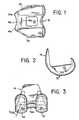
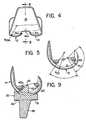
- FIG. 1-5illustrate a posterior-stabilized total knee prosthesis including a femoral component (Figs. 1-5) and a tibial component (Figs. 6-8).
- the illustrated prosthesisis a modified form of the Insall-Burstein knee.
- the femoral componentcomprises a pair of identical laterally spaced-apart femoral condyles 10 and 12, each of which is curved in lateral profile (Fig. 2) generally to match the convex curvature of an anatomical femoral condyle along its entire anterior-posterior extent.
- the anterior parts of the condylesmerge smoothly with convexly curved portions 14a and 14 b of a patellar flange 14, the middle part 14 c of which is concave.
- the middle patellar part 14cintersects at its lower extremity an anterior wall 16a of a box-like intercondylar portion 16.
- the anterior wall 16a and a femoral cam follower 20(described below) together with patellar portion 14, connect the condyles 10 and 12.
- a pair of laterally spaced-apart walls 16 b and 16 cjoin the patellar flange to the condyles and form the sides of the box-like intercondylar portion 16.
- the surfaces of the femoral component which face the surgically prepared femur boneare generally flat and, in the case of the "facets" of each condyle 10 and 12, are bounded by a small rib or flange 19 (Fig. 1) to provide a keying effect which holds the component securely on the cement used to attach the component to the femur.
- the upper surface of the anterior wall 16a of the intercondylar portion 16is generally flat. It slopes upwardly from its anterior surface toward a cam follower 20 at the posterior extremity of intercondylar portion 16, and includes a generally square opening 18.
- the femoral componentis preferably made of a surgical grade, durable metal, such as a 316L stainless steel or a chrome-cobalt-molybdenum alloy or ceramic material such as alumina or zirconia. All surfaces which are external to the bone are highly polished.
- the femoral componentis symmetrical about a vertical anterior-posterior center plane, so it can be used on either knee.
- the tibial componentis shown in Figs. 6-8 at 30. It may be made entirely of plastic (as shown) or it may include a plastic insert mounted on a metal tray. It is preferably made of a surgical grade, low friction, high molecular weight polyethylene. It is symmetrical about a vertical anterior-posterior center plane for right or left use. The upper surface of platform 30 slopes downwardly in the posterior direction. Two laterally spaced-apart, oblong concavities 32 and 34 are formed in the upper surface of plateau portion 30 to receive the femoral condyles 12 and 10, respectively.
- the "nested" support of the femoral componentstabilizes the prosthetic joint but still permits anterior-posterior translation, lateral angulation and axial rotation, all of which are involved in normal function of the anatomical knee joint.
- the lateral curvature of concavities 32 and 34is slightly greater than the lateral curvature of the femoral condyles 10 and 12.
- a fixation post 36extends from the bottom surface 31 of component 30. Cement intrudes into slots 38 in the walls of the fixation post and slots 40 on the bottom surface of the support and anchors the tibial component to the tibia.
- a stabilizing post 42extends upwardly from the plateau portion between the concavities 32 and 34 and is received in hole 18 of the femoral intercondylar portion 16.
- the post 42is generally triangular in lateral profile and has lateral surfaces, a posterior surface 42a which functions as a cam and an anterior upwardly sloping surface 42 b which functions as a hyperextension stop when contacting anterior wall 16a.
- the lateral surfaces of the stabilizing post 42are spaced sufficiently from the lateral walls of the femoral intercondylar recess to allow normal lateral angulation and rotation of the prosthetic knee joint.
- a generally stable positionis established by the nesting of the femoral condyles 10 and 12 in the tibial plateau concavities 34 and 32.
- the tibial stabilizing post 42 and femoral recess 16do not engage in the anterior-posterior direction. Under moderate degrees of flexion the post and recess continue to remain functionally dormant.
- the femoral cam 20tends to engage the posterior cam surface 42a of the tibial post 42 as the knee flexes.
- the femoral cam 20should ordinarily engage the tibial cam surface 42a and, as flexion increases beyond that point, force the prosthetic femoral condyles to roll back in the tibial concavities.
- the zone of contact between the condyles and the concavitiesshifts posteriorly to a location very close to the posterior extremity of the tibial plateau at full flexion. This shift and the sloping of the tibial plateau allows large flexion angles to be obtained without interference between the posterior extremity of the femur and the posterior extremity of the tibial component.
- the post and recessthus stabilize joint functions near and at full flexion by controlling the relative anterior-posterior positions of the femur and the tibia and by preventing anterior femoral translation.
- the anterior part of the wall 16a of the femoral intercondylar portion 16will engage the anterior surface of the tibial post 42 b and prevent hyperextension and posterior translation of the femur.
- the femoral condyles 10 and 12are nested in the tibial concavities 34 and 32. As indicated above, it is this relationship which is primarily responsible for knee stability, range of motion and durability.
- the proper selection of tibial concavity curvature and femoral condyle curvature in accordance with the inventionis particularly effective in reducing stress applied to the tibial platform when the knee undergoes varus or valgus angulation when bearing load.
- stress applied to the tibial platformis minimized under a compressive load; however, the range of motion, particularly axial rotation, is also reduced.
- the inventionby slightly modifying the radii of the curves of the condyles and concavities the invention provides increased durability, i.e. longevity, without diminishing stability, range of motion or axial rotation.
- the curve of the condyles 10 and 12 viewed in a lateral plainmay be defined by a radius designated as R CML .
- the curvature of the weight bearing surfaces of the condyles as viewed in an anterior-posterior planemay be defined by the radii R CE and R CF .
- the radius R CEdefines the curvature of the surface of the condyle which rests in a tibial concavity when the knee is in extension.
- the radius R CFdefines the curvature of the surface of the condyle that rests in a tibial concavity when the knee is in flexion.
- the surface of the tibial concavities 32 and 34are further defined by a medial-lateral radius R TML (Fig. 8) and anterior-posterior radius R TAP (Fig. 7).
- the optimum radii which have been established pursuant to the inventionmay be expressed as the ratio of the radii of the femoral condyles to the corresponding radii of the tibial concavities in both the medial/lateral and anterior/posterior directions. Since the condyles are defined by two radii in the anterior/posterior direction, i.e. the radii R CF and R CE representing, respectively, the weight bearing portions of the curvature when the knee is in flexion and extension, the relationships between the components may be defined by the ratios R CML /R TML , R CF /R TAP and R CE /R TAP .
- the ratiosare not necessarily the same for each available size.
- the illustrated embodiment of the inventionis shown in five different sizes and the following tables set forth the approximate ratios in accordance with the invention for five different sizes with size 1 being the smallest and size 5 being the largest.
- the tablesalso include the corresponding radii for the prior art Insall Burstein knee identified as "I-B II".
- the ratio R CML /R TMLis to be as close to the value of 1.00 as is obtainable consistent with obtaining adequate axial rotation when taken in combination with R CE /R TAP .
- the use of the value 1.00 for the ratio R CML /R TMLis not acceptable since this will overly restrict axial rotation.
- a value of R CML /R TML of about 0.96is preferred when used in combination with a value of R CE /R TAP of about 0.60 to 0.75.
- the contact-load-induced stresses on the tibial component in the illustrated embodimentwill be reduced because of the increase of the ratio R CML /R TML while at the same time the reduction of the ratio R CE /R TAP will tend to increase these stresses.
- the combination of the two changesresults in a net decrease in contact stresses without meaningful change in axial rotation of the knee joint.
- the ratio R CF /R TAPis to be about 0.4 to 0.5. This value will independently contribute to lower contact-load-induced stresses as compared to the I-BII, while not decreasing axial rotation meaningfully.
- the indicated values of R CF /R TAPproduce greater axial rotation in the flexed position of the knee joint than that produced by the corresponding radii of curvature when the knee is in the extended position.
- the radii R CE of the femoral condyles 10 and 12have been substantially reduced.
- the effectis to remove bulk from the condyles and thereby reduce tension in the soft tissues that attach to the medial and lateral sides of the patella (not illustrated). This reduces complications which can occur at the patella-femoral joints, such as dislocation, subluxation (i.e. movement of the patella in and out of the trochlea grove), pain and even possible fracture of the patella.
- the height of the anterior portion of the femoral componenthas been increased. This enhances the ability of the knee to engage the patella when the knee is fully extended.
- the tibial post 42has been increased in height and the cam surface 42a moved in a posterior direction.
- the increased height of post 42makes it more difficult for the femoral component to slip over the post.
- Repositioning the cam surface 42aallows an essentially uniform range of motion for all size prosthetic knee joints.
Landscapes
- Health & Medical Sciences (AREA)
- Orthopedic Medicine & Surgery (AREA)
- Physical Education & Sports Medicine (AREA)
- Cardiology (AREA)
- Oral & Maxillofacial Surgery (AREA)
- Transplantation (AREA)
- Engineering & Computer Science (AREA)
- Biomedical Technology (AREA)
- Heart & Thoracic Surgery (AREA)
- Vascular Medicine (AREA)
- Life Sciences & Earth Sciences (AREA)
- Animal Behavior & Ethology (AREA)
- General Health & Medical Sciences (AREA)
- Public Health (AREA)
- Veterinary Medicine (AREA)
- Prostheses (AREA)
- Materials For Medical Uses (AREA)
Abstract
Description


Claims (4)
- A joint prosthesis comprising:characterized in thata first component which includes a pair of laterally spaced apart condyles (10, 12),the surface of each said condyle being defined at least in part by (a) anterior posterior radiiRCF and RCE, wherein RCF is the radius of curvature of that portion of the condyle which isweight bearing in flexion and RCE represents that portion of the curvature of the condylewhich is weight bearing in extension, and (b) a medial lateral radius RCML; anda second component, at least a portion of which is made of a plastic material andincludes a pair of laterally spaced apart concavities (32, 34), each of which is adapted toreceive one of the condyles (10, 12) of the first component, the articulating surfaces of suchconcavities being defined by an anterior posterior radius RTAP and a medial lateral radiusRTML,
said condyles (10, 12) and concavities (32, 34) are formed such that the ratioRCML/RTML is about 0.96 and the ratio RCE/RTAP is between 0.60 and 0.75. - A joint prosthesis according to claim 1, wherein said condyles and concavities areformed such that the ratio RCF/RTAP is between 0.4 and 0.5.
- A joint prosthesis according to anyone of claims 1 or 2,characterized in that
said first component is a femoral component in which each of said laterally spacedapart condyles is curved generally to be similar to the shape of an anatomical femoral condyle;
and said second component is a tibial component. - A knee joint prosthesis according to claim 3, wherein said tibial component includesan upwardly extending post (42) having a posterior concavely curved cam portion(42a), and wherein
said femoral component includes a cam follower portion (20) adapted to engagesaid cam portion (42a) to provide posterior stabilization, the cam follower and cam surfacesbeing arranged such that they engage each other when the knee is flexed about 60-65 degrees.
Applications Claiming Priority (3)
| Application Number | Priority Date | Filing Date | Title |
|---|---|---|---|
| US08/383,757US5702458A (en) | 1994-12-09 | 1995-02-02 | Joint prosthesis |
| US383757 | 1995-02-02 | ||
| PCT/US1996/001732WO1996023460A1 (en) | 1995-02-02 | 1996-01-26 | Joint prosthesis |
Publications (3)
| Publication Number | Publication Date |
|---|---|
| EP0806920A1 EP0806920A1 (en) | 1997-11-19 |
| EP0806920A4 EP0806920A4 (en) | 1998-12-02 |
| EP0806920B1true EP0806920B1 (en) | 2002-12-11 |
Family
ID=23514598
Family Applications (1)
| Application Number | Title | Priority Date | Filing Date |
|---|---|---|---|
| EP96903803AExpired - LifetimeEP0806920B1 (en) | 1995-02-02 | 1996-01-26 | Joint prosthesis |
Country Status (10)
| Country | Link |
|---|---|
| US (1) | US5702458A (en) |
| EP (1) | EP0806920B1 (en) |
| JP (1) | JPH10513371A (en) |
| KR (2) | KR19980701639A (en) |
| AT (1) | ATE229308T1 (en) |
| AU (1) | AU697225B2 (en) |
| CA (1) | CA2210531C (en) |
| DE (1) | DE69625334T2 (en) |
| ES (1) | ES2189863T3 (en) |
| WO (1) | WO1996023460A1 (en) |
Cited By (1)
| Publication number | Priority date | Publication date | Assignee | Title |
|---|---|---|---|---|
| US8394148B2 (en) | 2002-12-20 | 2013-03-12 | Smith & Nephew, Inc. | Tibial component of high performance knee prosthesis |
Families Citing this family (90)
| Publication number | Priority date | Publication date | Assignee | Title |
|---|---|---|---|---|
| US8603095B2 (en) | 1994-09-02 | 2013-12-10 | Puget Bio Ventures LLC | Apparatuses for femoral and tibial resection |
| US6695848B2 (en) | 1994-09-02 | 2004-02-24 | Hudson Surgical Design, Inc. | Methods for femoral and tibial resection |
| HU219444B (en)* | 1996-02-26 | 2001-04-28 | Gábor Krakovits | Sliding surface for knee-joint prothesis |
| US5928285A (en)* | 1997-05-30 | 1999-07-27 | Bristol-Myers Squibb Co. | Orthopaedic implant having an articulating surface with a conforming and translational surface |
| US6039764A (en)* | 1997-08-18 | 2000-03-21 | Arch Development Corporation | Prosthetic knee with adjusted center of internal/external rotation |
| US6325828B1 (en)* | 1997-12-02 | 2001-12-04 | Rose Biomedical Research | Apparatus for knee prosthesis |
| US6443991B1 (en)* | 1998-09-21 | 2002-09-03 | Depuy Orthopaedics, Inc. | Posterior stabilized mobile bearing knee |
| US6152960A (en)* | 1998-10-13 | 2000-11-28 | Biomedical Engineering Trust I | Femoral component for knee endoprosthesis |
| US6165223A (en)* | 1999-03-01 | 2000-12-26 | Biomet, Inc. | Floating bearing knee joint prosthesis with a fixed tibial post |
| US6972039B2 (en) | 1999-03-01 | 2005-12-06 | Biomet, Inc. | Floating bearing knee joint prosthesis with a fixed tibial post |
| US6413279B1 (en) | 1999-03-01 | 2002-07-02 | Biomet, Inc. | Floating bearing knee joint prosthesis with a fixed tibial post |
| ITVI20000025U1 (en)* | 2000-04-07 | 2001-10-07 | Tecres Spa | TEMPORARY SPACER DEVICE FOR SURGICAL TREATMENT OF THE KNEE |
| FR2809302B1 (en)* | 2000-05-23 | 2003-03-21 | Didier Baert | ORTHOPEDIC IMPLANTS AND MORE PARTICULARLY KNEE PROSTHESES |
| JP3679315B2 (en)* | 2000-07-19 | 2005-08-03 | 経憲 武井 | Knee prosthesis |
| US6558426B1 (en) | 2000-11-28 | 2003-05-06 | Medidea, Llc | Multiple-cam, posterior-stabilized knee prosthesis |
| US6355037B1 (en) | 2000-12-05 | 2002-03-12 | Smith & Nephew, Inc. | Apparatus and method of external skeletal support allowing for internal-external rotation |
| US6485519B2 (en)* | 2001-01-29 | 2002-11-26 | Bristol-Myers Squibb Company | Constrained prosthetic knee with rotating bearing |
| US6719800B2 (en) | 2001-01-29 | 2004-04-13 | Zimmer Technology, Inc. | Constrained prosthetic knee with rotating bearing |
| US6773461B2 (en) | 2001-01-29 | 2004-08-10 | Zimmer Technology, Inc. | Constrained prosthetic knee with rotating bearing |
| US8123814B2 (en) | 2001-02-23 | 2012-02-28 | Biomet Manufacturing Corp. | Method and appartus for acetabular reconstruction |
| US8062377B2 (en) | 2001-03-05 | 2011-11-22 | Hudson Surgical Design, Inc. | Methods and apparatus for knee arthroplasty |
| ES2368422T3 (en)* | 2001-04-17 | 2011-11-17 | Exactech, Inc. | ARTICULATION OF KNEE PROTESIC. |
| US7776085B2 (en) | 2001-05-01 | 2010-08-17 | Amedica Corporation | Knee prosthesis with ceramic tibial component |
| US7695521B2 (en) | 2001-05-01 | 2010-04-13 | Amedica Corporation | Hip prosthesis with monoblock ceramic acetabular cup |
| EP1408874B1 (en) | 2001-06-14 | 2012-08-08 | Amedica Corporation | Metal-ceramic composite articulation |
| US20030009230A1 (en)* | 2001-06-30 | 2003-01-09 | Gundlapalli Rama Rao V. | Surface sterilizable joint replacement prosthesis component with insert |
| DE10220591B4 (en)* | 2002-05-08 | 2004-03-18 | Mathys Medizinaltechnik Ag | Joint prosthesis with an intermediate element with different radii of curvature |
| AU2003297195A1 (en) | 2002-12-17 | 2004-07-22 | Amedica Corporation | Total disc implant |
| CA2512617C (en) | 2003-02-08 | 2010-05-18 | Depuy International Limited | A knee joint prosthesis |
| CA2542619C (en) | 2003-10-17 | 2011-10-11 | Smith & Nephew, Inc. | High flexion articular insert |
| US20060030854A1 (en) | 2004-02-02 | 2006-02-09 | Haines Timothy G | Methods and apparatus for wireplasty bone resection |
| US9814539B2 (en) | 2004-01-14 | 2017-11-14 | Puget Bioventures Llc | Methods and apparatus for conformable prosthetic implants |
| US8114083B2 (en) | 2004-01-14 | 2012-02-14 | Hudson Surgical Design, Inc. | Methods and apparatus for improved drilling and milling tools for resection |
| US8021368B2 (en) | 2004-01-14 | 2011-09-20 | Hudson Surgical Design, Inc. | Methods and apparatus for improved cutting tools for resection |
| US8043294B2 (en)* | 2004-03-05 | 2011-10-25 | Wright Medical Technology, Inc. | Reference mark adjustment mechanism for a femoral caliper and method of using the same |
| JP3915989B2 (en)* | 2004-03-17 | 2007-05-16 | 徹 勝呂 | Artificial knee joint |
| US7731755B2 (en)* | 2004-06-11 | 2010-06-08 | Depuy Products, Inc. | Posterior stabilized mobile bearing knee |
| US8303597B2 (en) | 2005-02-08 | 2012-11-06 | Rasmussen G Lynn | Systems and methods for guiding cuts to a femur and tibia during a knee arthroplasty |
| US7927336B2 (en)* | 2005-02-08 | 2011-04-19 | Rasmussen G Lynn | Guide assembly for guiding cuts to a femur and tibia during a knee arthroplasty |
| US8317797B2 (en) | 2005-02-08 | 2012-11-27 | Rasmussen G Lynn | Arthroplasty systems and methods for optimally aligning and tensioning a knee prosthesis |
| US20070100460A1 (en)* | 2005-10-27 | 2007-05-03 | Rhodes James M | Orthopaedic implant systems with anti-abrasion studs |
| US8216319B2 (en)* | 2005-10-27 | 2012-07-10 | Depuy Products, Inc. | Method of repairing a knee joint |
| US7635447B2 (en) | 2006-02-17 | 2009-12-22 | Biomet Manufacturing Corp. | Method and apparatus for forming porous metal implants |
| EP1996122B1 (en) | 2006-03-21 | 2012-11-21 | DePuy (Ireland) | Moment induced total arthroplasty prosthetic |
| CA2656359C (en) | 2006-06-30 | 2016-11-22 | Smith & Nephew, Inc. | Anatomical motion hinged prosthesis |
| US7875081B2 (en)* | 2006-09-25 | 2011-01-25 | New York Society For The Ruptured And Crippled Maintaining The Hospital For Special Surgery | Posterior stabilized knee prosthesis |
| US8142510B2 (en)* | 2007-03-30 | 2012-03-27 | Depuy Products, Inc. | Mobile bearing assembly having a non-planar interface |
| US8328874B2 (en)* | 2007-03-30 | 2012-12-11 | Depuy Products, Inc. | Mobile bearing assembly |
| US8147558B2 (en)* | 2007-03-30 | 2012-04-03 | Depuy Products, Inc. | Mobile bearing assembly having multiple articulation interfaces |
| US8764841B2 (en)* | 2007-03-30 | 2014-07-01 | DePuy Synthes Products, LLC | Mobile bearing assembly having a closed track |
| US8147557B2 (en)* | 2007-03-30 | 2012-04-03 | Depuy Products, Inc. | Mobile bearing insert having offset dwell point |
| CN101842062B (en)* | 2007-09-25 | 2013-04-03 | 拜欧米特制造公司 | Method for manufacturing cementless tibial tray |
| US8128703B2 (en) | 2007-09-28 | 2012-03-06 | Depuy Products, Inc. | Fixed-bearing knee prosthesis having interchangeable components |
| US8632600B2 (en) | 2007-09-25 | 2014-01-21 | Depuy (Ireland) | Prosthesis with modular extensions |
| US9204967B2 (en) | 2007-09-28 | 2015-12-08 | Depuy (Ireland) | Fixed-bearing knee prosthesis having interchangeable components |
| KR100904087B1 (en)* | 2008-01-08 | 2009-06-23 | 주식회사 코렌텍 | Artificial knee joint with curvature in bearing member |
| CN101977570B (en)* | 2008-02-11 | 2013-08-14 | 精密技术公司 | Knee prosthesis system with slope |
| US9168145B2 (en) | 2008-06-30 | 2015-10-27 | Depuy (Ireland) | Posterior stabilized orthopaedic knee prosthesis having controlled condylar curvature |
| US8187335B2 (en) | 2008-06-30 | 2012-05-29 | Depuy Products, Inc. | Posterior stabilized orthopaedic knee prosthesis having controlled condylar curvature |
| US9119723B2 (en) | 2008-06-30 | 2015-09-01 | Depuy (Ireland) | Posterior stabilized orthopaedic prosthesis assembly |
| US8828086B2 (en) | 2008-06-30 | 2014-09-09 | Depuy (Ireland) | Orthopaedic femoral component having controlled condylar curvature |
| US8192498B2 (en) | 2008-06-30 | 2012-06-05 | Depuy Products, Inc. | Posterior cructiate-retaining orthopaedic knee prosthesis having controlled condylar curvature |
| US8206451B2 (en) | 2008-06-30 | 2012-06-26 | Depuy Products, Inc. | Posterior stabilized orthopaedic prosthesis |
| US8480752B2 (en)* | 2008-06-30 | 2013-07-09 | DePuy Synthes Products, LLC | Tibial bearing having increased axial-rotation |
| US8236061B2 (en) | 2008-06-30 | 2012-08-07 | Depuy Products, Inc. | Orthopaedic knee prosthesis having controlled condylar curvature |
| US8202323B2 (en)* | 2008-07-16 | 2012-06-19 | Depuy Products, Inc. | Knee prostheses with enhanced kinematics |
| US8491662B2 (en) | 2008-12-23 | 2013-07-23 | Aesculap Ag | Knee prosthesis |
| US20100161067A1 (en)* | 2008-12-23 | 2010-06-24 | Aesculap Ag | Knee prosthesis |
| US9220600B2 (en) | 2008-12-23 | 2015-12-29 | Aesculap Implant Systems, Llc | Knee prosthesis |
| FR2940760B1 (en)* | 2009-01-08 | 2010-12-31 | Memometal Technologies | ORTHOPEDIC IMPLANT FOR DIGITAL ARTHROPLASTY |
| FR2940759B1 (en)* | 2009-01-08 | 2011-10-07 | Memometal Technologies | INTRA MEDULLAIRE ANCHORING ROD FOR ORTHOPEDIC IMPLANT HEAD |
| CN105380733B (en)* | 2009-03-27 | 2021-09-14 | 史密夫和内修整形外科股份公司 | Artificial knee joint |
| CA2756226C (en)* | 2009-03-27 | 2017-01-24 | Smith & Nephew Orthopaedics Ag | Artificial knee joint |
| US8915965B2 (en) | 2009-05-07 | 2014-12-23 | Depuy (Ireland) | Anterior stabilized knee implant |
| DE202009008370U1 (en)* | 2009-06-17 | 2010-10-28 | Lawton Gmbh & Co. Kg | Surgical instrument |
| US8383033B2 (en) | 2009-10-08 | 2013-02-26 | Biomet Manufacturing Corp. | Method of bonding porous metal to metal substrates |
| US8870964B2 (en) | 2009-11-16 | 2014-10-28 | New York Society For The Ruptured And Crippled Maintaining The Hospital For Special Surgery | Prosthetic condylar joints with articulating bearing surfaces having a translating contact point during rotation thereof |
| JP5775092B2 (en)* | 2009-12-09 | 2015-09-09 | ザ・ジエネラル・ホスピタル・コーポレーシヨン・ドウーイング・ビジネス・アズ・マサチユセツツ・ジエネラル・ホスピタル | Implants that repair the normal range of knee flexion and movement |
| US9011547B2 (en) | 2010-01-21 | 2015-04-21 | Depuy (Ireland) | Knee prosthesis system |
| US8900316B2 (en) | 2010-01-29 | 2014-12-02 | Smith & Nephew, Inc. | Cruciate-retaining knee prosthesis |
| US8308808B2 (en) | 2010-02-19 | 2012-11-13 | Biomet Manufacturing Corp. | Latent mobile bearing for prosthetic device |
| CA2808090C (en) | 2010-08-12 | 2018-09-11 | Smith & Nephew, Inc. | Structures for use in orthopaedic implant fixation and methods of installation onto a bone |
| US8747479B2 (en) | 2011-04-26 | 2014-06-10 | Michael A. McShane | Tibial component |
| JP6472658B2 (en)* | 2011-06-30 | 2019-02-20 | デピュイ・アイルランド・アンリミテッド・カンパニーDepuy Ireland Unlimited Company | Retrostable orthopedic knee prosthesis with controlled condyle curvature |
| EP2726021B1 (en)* | 2011-06-30 | 2015-11-04 | DePuy (Ireland) | Posterior stabilized orthopaedic prosthesis assembly |
| WO2014124233A1 (en)* | 2013-02-08 | 2014-08-14 | Orthopaedic International, Inc. | Instruments and methods for locating a femoral mechanical axis |
| DE102013205156B4 (en) | 2013-03-22 | 2015-02-12 | Heraeus Medical Gmbh | Knee spacer for temporary replacement of an artificial knee joint |
| US10179052B2 (en) | 2016-07-28 | 2019-01-15 | Depuy Ireland Unlimited Company | Total knee implant prosthesis assembly and method |
| US12414862B2 (en) | 2016-11-30 | 2025-09-16 | G. Lynn Rasmussen | Systems and methods for providing a tibial baseplate system |
| JP2020500600A (en) | 2016-11-30 | 2020-01-16 | ジー リン ラスムッセン | System and method for providing a tibial baseplate |
Family Cites Families (7)
| Publication number | Priority date | Publication date | Assignee | Title |
|---|---|---|---|---|
| US4213209A (en)* | 1978-05-22 | 1980-07-22 | New York Society For The Relief Of The Ruptured And Crippled | Knee joint prosthesis |
| US4309778A (en)* | 1979-07-02 | 1982-01-12 | Biomedical Engineering Corp. | New Jersey meniscal bearing knee replacement |
| US4298992A (en)* | 1980-01-21 | 1981-11-10 | New York Society For The Relief Of The Ruptured And Crippled | Posteriorly stabilized total knee joint prosthesis |
| US5011496A (en)* | 1988-02-02 | 1991-04-30 | Joint Medical Products Corporation | Prosthetic joint |
| US4892547A (en)* | 1988-02-03 | 1990-01-09 | Biomet, Inc. | Partially stabilized knee prosthesis |
| US5147405A (en)* | 1990-02-07 | 1992-09-15 | Boehringer Mannheim Corporation | Knee prosthesis |
| US5370699A (en)* | 1993-01-21 | 1994-12-06 | Orthomet, Inc. | Modular knee joint prosthesis |
- 1995
- 1995-02-02USUS08/383,757patent/US5702458A/ennot_activeExpired - Lifetime
- 1996
- 1996-01-26ATAT96903803Tpatent/ATE229308T1/ennot_activeIP Right Cessation
- 1996-01-26JPJP8523791Apatent/JPH10513371A/enactivePending
- 1996-01-26ESES96903803Tpatent/ES2189863T3/ennot_activeExpired - Lifetime
- 1996-01-26CACA002210531Apatent/CA2210531C/ennot_activeExpired - Lifetime
- 1996-01-26KRKR1019970705033Apatent/KR19980701639A/ennot_activeWithdrawn
- 1996-01-26DEDE69625334Tpatent/DE69625334T2/ennot_activeExpired - Lifetime
- 1996-01-26AUAU47773/96Apatent/AU697225B2/ennot_activeExpired
- 1996-01-26WOPCT/US1996/001732patent/WO1996023460A1/enactiveIP Right Grant
- 1996-01-26EPEP96903803Apatent/EP0806920B1/ennot_activeExpired - Lifetime
- 1997
- 1997-07-24KRKR19977005033Apatent/KR19987001639A/enactivePending
Cited By (12)
| Publication number | Priority date | Publication date | Assignee | Title |
|---|---|---|---|---|
| US8394148B2 (en) | 2002-12-20 | 2013-03-12 | Smith & Nephew, Inc. | Tibial component of high performance knee prosthesis |
| US8394147B2 (en) | 2002-12-20 | 2013-03-12 | Smith & Nephew, Inc. | High performance femoral knee prostheses |
| US8398716B2 (en) | 2002-12-20 | 2013-03-19 | Smith & Nephew, Inc. | High performance knee prostheses with posterior cam |
| US8398715B2 (en) | 2002-12-20 | 2013-03-19 | Smith & Nephew, Inc. | High performance knee prostheses with converging anterior and posterior portions |
| US8403992B2 (en) | 2002-12-20 | 2013-03-26 | Smith & Nephew, Inc. | High performance knee prostheses |
| US8425617B2 (en) | 2002-12-20 | 2013-04-23 | Smith & Nephew, Inc. | Knee prostheses with convex slope on portion of tibial articular surface |
| US8449618B2 (en) | 2002-12-20 | 2013-05-28 | Smith & Nephew, Inc. | High performance knee prostheses |
| US8603178B2 (en) | 2002-12-20 | 2013-12-10 | Smith & Nephew, Inc. | Knee prostheses with convex portion on tibial lateral articular surface |
| US8647389B2 (en) | 2002-12-20 | 2014-02-11 | Smith & Nephew, Inc. | High performance knee prostheses |
| US8652210B2 (en) | 2002-12-20 | 2014-02-18 | Smith & Nephew, Inc. | Femoral prostheses with lateral buttress for patella |
| US9320605B2 (en) | 2002-12-20 | 2016-04-26 | Smith & Nephew, Inc. | High performance knee prostheses |
| US9402729B2 (en) | 2002-12-20 | 2016-08-02 | Smith & Nephew, Inc. | High performance knee prostheses |
Also Published As
| Publication number | Publication date |
|---|---|
| WO1996023460A1 (en) | 1996-08-08 |
| AU697225B2 (en) | 1998-10-01 |
| ATE229308T1 (en) | 2002-12-15 |
| KR19980701639A (en) | 1998-06-25 |
| ES2189863T3 (en) | 2003-07-16 |
| CA2210531A1 (en) | 1996-08-08 |
| DE69625334D1 (en) | 2003-01-23 |
| EP0806920A4 (en) | 1998-12-02 |
| AU4777396A (en) | 1996-08-21 |
| US5702458A (en) | 1997-12-30 |
| CA2210531C (en) | 2007-03-20 |
| KR19987001639A (en) | 1998-06-25 |
| EP0806920A1 (en) | 1997-11-19 |
| JPH10513371A (en) | 1998-12-22 |
| DE69625334T2 (en) | 2004-06-17 |
Similar Documents
| Publication | Publication Date | Title |
|---|---|---|
| EP0806920B1 (en) | Joint prosthesis | |
| US4298992A (en) | Posteriorly stabilized total knee joint prosthesis | |
| US5330532A (en) | Knee joint prosthesis | |
| US5171283A (en) | Compound shape rotating bearing | |
| US5871542A (en) | Endoprosthetic knee joint device | |
| US4207627A (en) | Knee prosthesis | |
| EP1333785B1 (en) | Floating bearing knee joint prosthesis with a fixed tibial post | |
| US8382847B2 (en) | Posterior stabilized knee with varus-valgus constraint | |
| EP2254519B1 (en) | Total knee replacement prosthesis | |
| US5935173A (en) | Knee prosthesis | |
| US5997577A (en) | Knee joint prosthesis | |
| CA2449287C (en) | Femoral prosthesis | |
| US6730128B2 (en) | Prosthetic knee joint | |
| US4081866A (en) | Total anatomical knee prosthesis | |
| EP0327297B1 (en) | Prosthetic knee joint with improved patellar component tracking | |
| US20180161164A1 (en) | Posteriorly stabilized total knee joint prosthesis | |
| AU714764B2 (en) | Knee prosthesis | |
| AU2011221425A1 (en) | High flexion articular insert |
Legal Events
| Date | Code | Title | Description |
|---|---|---|---|
| PUAI | Public reference made under article 153(3) epc to a published international application that has entered the european phase | Free format text:ORIGINAL CODE: 0009012 | |
| 17P | Request for examination filed | Effective date:19970731 | |
| AK | Designated contracting states | Kind code of ref document:A1 Designated state(s):AT BE CH DE DK ES FR GB GR IE IT LI LU MC NL PT SE | |
| A4 | Supplementary search report drawn up and despatched | Effective date:19981021 | |
| AK | Designated contracting states | Kind code of ref document:A4 Designated state(s):AT BE CH DE DK ES FR GB GR IE IT LI LU MC NL PT SE | |
| 17Q | First examination report despatched | Effective date:20010711 | |
| GRAG | Despatch of communication of intention to grant | Free format text:ORIGINAL CODE: EPIDOS AGRA | |
| GRAG | Despatch of communication of intention to grant | Free format text:ORIGINAL CODE: EPIDOS AGRA | |
| GRAH | Despatch of communication of intention to grant a patent | Free format text:ORIGINAL CODE: EPIDOS IGRA | |
| GRAH | Despatch of communication of intention to grant a patent | Free format text:ORIGINAL CODE: EPIDOS IGRA | |
| GRAA | (expected) grant | Free format text:ORIGINAL CODE: 0009210 | |
| AK | Designated contracting states | Kind code of ref document:B1 Designated state(s):AT BE CH DE DK ES FR GB GR IE IT LI LU MC NL PT SE | |
| PG25 | Lapsed in a contracting state [announced via postgrant information from national office to epo] | Ref country code:NL Free format text:LAPSE BECAUSE OF FAILURE TO SUBMIT A TRANSLATION OF THE DESCRIPTION OR TO PAY THE FEE WITHIN THE PRESCRIBED TIME-LIMIT Effective date:20021211 Ref country code:GR Free format text:LAPSE BECAUSE OF FAILURE TO SUBMIT A TRANSLATION OF THE DESCRIPTION OR TO PAY THE FEE WITHIN THE PRESCRIBED TIME-LIMIT Effective date:20021211 Ref country code:BE Free format text:LAPSE BECAUSE OF FAILURE TO SUBMIT A TRANSLATION OF THE DESCRIPTION OR TO PAY THE FEE WITHIN THE PRESCRIBED TIME-LIMIT Effective date:20021211 Ref country code:AT Free format text:LAPSE BECAUSE OF FAILURE TO SUBMIT A TRANSLATION OF THE DESCRIPTION OR TO PAY THE FEE WITHIN THE PRESCRIBED TIME-LIMIT Effective date:20021211 | |
| REF | Corresponds to: | Ref document number:229308 Country of ref document:AT Date of ref document:20021215 Kind code of ref document:T | |
| REG | Reference to a national code | Ref country code:GB Ref legal event code:FG4D | |
| REG | Reference to a national code | Ref country code:CH Ref legal event code:EP | |
| REG | Reference to a national code | Ref country code:IE Ref legal event code:FG4D | |
| REF | Corresponds to: | Ref document number:69625334 Country of ref document:DE Date of ref document:20030123 | |
| PG25 | Lapsed in a contracting state [announced via postgrant information from national office to epo] | Ref country code:LU Free format text:LAPSE BECAUSE OF NON-PAYMENT OF DUE FEES Effective date:20030126 | |
| PG25 | Lapsed in a contracting state [announced via postgrant information from national office to epo] | Ref country code:IE Free format text:LAPSE BECAUSE OF NON-PAYMENT OF DUE FEES Effective date:20030127 | |
| PG25 | Lapsed in a contracting state [announced via postgrant information from national office to epo] | Ref country code:MC Free format text:LAPSE BECAUSE OF NON-PAYMENT OF DUE FEES Effective date:20030131 | |
| PG25 | Lapsed in a contracting state [announced via postgrant information from national office to epo] | Ref country code:SE Free format text:LAPSE BECAUSE OF FAILURE TO SUBMIT A TRANSLATION OF THE DESCRIPTION OR TO PAY THE FEE WITHIN THE PRESCRIBED TIME-LIMIT Effective date:20030311 Ref country code:PT Free format text:LAPSE BECAUSE OF FAILURE TO SUBMIT A TRANSLATION OF THE DESCRIPTION OR TO PAY THE FEE WITHIN THE PRESCRIBED TIME-LIMIT Effective date:20030311 Ref country code:DK Free format text:LAPSE BECAUSE OF FAILURE TO SUBMIT A TRANSLATION OF THE DESCRIPTION OR TO PAY THE FEE WITHIN THE PRESCRIBED TIME-LIMIT Effective date:20030311 | |
| NLV1 | Nl: lapsed or annulled due to failure to fulfill the requirements of art. 29p and 29m of the patents act | ||
| REG | Reference to a national code | Ref country code:CH Ref legal event code:NV Representative=s name:BUGNION S.A. | |
| ET | Fr: translation filed | ||
| REG | Reference to a national code | Ref country code:ES Ref legal event code:FG2A Ref document number:2189863 Country of ref document:ES Kind code of ref document:T3 | |
| PLBE | No opposition filed within time limit | Free format text:ORIGINAL CODE: 0009261 | |
| STAA | Information on the status of an ep patent application or granted ep patent | Free format text:STATUS: NO OPPOSITION FILED WITHIN TIME LIMIT | |
| REG | Reference to a national code | Ref country code:IE Ref legal event code:MM4A | |
| 26N | No opposition filed | Effective date:20030912 | |
| REG | Reference to a national code | Ref country code:FR Ref legal event code:PLFP Year of fee payment:20 | |
| PGFP | Annual fee paid to national office [announced via postgrant information from national office to epo] | Ref country code:DE Payment date:20150128 Year of fee payment:20 Ref country code:ES Payment date:20150126 Year of fee payment:20 Ref country code:CH Payment date:20150126 Year of fee payment:20 Ref country code:IT Payment date:20150126 Year of fee payment:20 | |
| PGFP | Annual fee paid to national office [announced via postgrant information from national office to epo] | Ref country code:GB Payment date:20150127 Year of fee payment:20 Ref country code:FR Payment date:20150119 Year of fee payment:20 | |
| REG | Reference to a national code | Ref country code:DE Ref legal event code:R071 Ref document number:69625334 Country of ref document:DE | |
| REG | Reference to a national code | Ref country code:CH Ref legal event code:PL | |
| REG | Reference to a national code | Ref country code:GB Ref legal event code:PE20 Expiry date:20160125 | |
| PG25 | Lapsed in a contracting state [announced via postgrant information from national office to epo] | Ref country code:GB Free format text:LAPSE BECAUSE OF EXPIRATION OF PROTECTION Effective date:20160125 | |
| REG | Reference to a national code | Ref country code:ES Ref legal event code:FD2A Effective date:20160504 | |
| PG25 | Lapsed in a contracting state [announced via postgrant information from national office to epo] | Ref country code:ES Free format text:LAPSE BECAUSE OF EXPIRATION OF PROTECTION Effective date:20160127 |