EP0806211B1 - Implant material and process for producing it - Google Patents
Implant material and process for producing itDownload PDFInfo
- Publication number
- EP0806211B1 EP0806211B1EP97201424AEP97201424AEP0806211B1EP 0806211 B1EP0806211 B1EP 0806211B1EP 97201424 AEP97201424 AEP 97201424AEP 97201424 AEP97201424 AEP 97201424AEP 0806211 B1EP0806211 B1EP 0806211B1
- Authority
- EP
- European Patent Office
- Prior art keywords
- coating
- calcium phosphate
- implantable device
- immersion
- titanium
- Prior art date
- Legal status (The legal status is an assumption and is not a legal conclusion. Google has not performed a legal analysis and makes no representation as to the accuracy of the status listed.)
- Expired - Lifetime
Links
- 239000007943implantSubstances0.000titleclaimsdescription22
- 239000000463materialSubstances0.000titleclaimsdescription19
- 238000000034methodMethods0.000titleclaimsdescription15
- 230000008569processEffects0.000titleclaimsdescription6
- 239000001506calcium phosphateSubstances0.000claimsdescription51
- QORWJWZARLRLPR-UHFFFAOYSA-Htricalcium bis(phosphate)Chemical compound[Ca+2].[Ca+2].[Ca+2].[O-]P([O-])([O-])=O.[O-]P([O-])([O-])=OQORWJWZARLRLPR-UHFFFAOYSA-H0.000claimsdescription51
- 229910000389calcium phosphateInorganic materials0.000claimsdescription50
- 235000011010calcium phosphatesNutrition0.000claimsdescription50
- 230000003746surface roughnessEffects0.000claimsdescription17
- 238000011282treatmentMethods0.000claimsdescription15
- 239000000126substanceSubstances0.000claimsdescription8
- 229910052751metalInorganic materials0.000claimsdescription7
- 239000002184metalSubstances0.000claimsdescription7
- 238000004381surface treatmentMethods0.000claimsdescription7
- 239000011148porous materialSubstances0.000claimsdescription6
- 239000002131composite materialSubstances0.000claimsdescription3
- 229910003460diamondInorganic materials0.000claimsdescription3
- 239000010432diamondSubstances0.000claimsdescription3
- 238000001356surgical procedureMethods0.000claimsdescription3
- 239000000316bone substituteSubstances0.000claimsdescription2
- 229910010293ceramic materialInorganic materials0.000claimsdescription2
- 239000004053dental implantSubstances0.000claimsdescription2
- 229920005615natural polymerPolymers0.000claimsdescription2
- 229920001059synthetic polymerPolymers0.000claimsdescription2
- 230000002378acidificating effectEffects0.000claims1
- 238000004519manufacturing processMethods0.000claims1
- 229910001092metal group alloyInorganic materials0.000claims1
- 238000009991scouringMethods0.000claims1
- 238000000576coating methodMethods0.000description55
- 239000011248coating agentSubstances0.000description39
- 239000011575calciumSubstances0.000description31
- 238000007654immersionMethods0.000description31
- 239000010936titaniumSubstances0.000description31
- 239000012981Hank's balanced salt solutionSubstances0.000description23
- 229910000883Ti6Al4VInorganic materials0.000description23
- 229910052791calciumInorganic materials0.000description22
- RTAQQCXQSZGOHL-UHFFFAOYSA-NTitaniumChemical compound[Ti]RTAQQCXQSZGOHL-UHFFFAOYSA-N0.000description20
- 239000000243solutionSubstances0.000description20
- 229910052719titaniumInorganic materials0.000description19
- 239000000758substrateSubstances0.000description15
- 229910052698phosphorusInorganic materials0.000description13
- 239000002244precipitateSubstances0.000description12
- 238000001556precipitationMethods0.000description12
- 239000000523sampleSubstances0.000description11
- OYPRJOBELJOOCE-UHFFFAOYSA-NCalciumChemical compound[Ca]OYPRJOBELJOOCE-UHFFFAOYSA-N0.000description10
- GWEVSGVZZGPLCZ-UHFFFAOYSA-NTitan oxideChemical compoundO=[Ti]=OGWEVSGVZZGPLCZ-UHFFFAOYSA-N0.000description9
- 229910052586apatiteInorganic materials0.000description9
- 230000003592biomimetic effectEffects0.000description9
- 229910052588hydroxylapatiteInorganic materials0.000description9
- VSIIXMUUUJUKCM-UHFFFAOYSA-Dpentacalcium;fluoride;triphosphateChemical compound[F-].[Ca+2].[Ca+2].[Ca+2].[Ca+2].[Ca+2].[O-]P([O-])([O-])=O.[O-]P([O-])([O-])=O.[O-]P([O-])([O-])=OVSIIXMUUUJUKCM-UHFFFAOYSA-D0.000description9
- XYJRXVWERLGGKC-UHFFFAOYSA-Dpentacalcium;hydroxide;triphosphateChemical compound[OH-].[Ca+2].[Ca+2].[Ca+2].[Ca+2].[Ca+2].[O-]P([O-])([O-])=O.[O-]P([O-])([O-])=O.[O-]P([O-])([O-])=OXYJRXVWERLGGKC-UHFFFAOYSA-D0.000description9
- 238000004626scanning electron microscopyMethods0.000description9
- 229910052715tantalumInorganic materials0.000description9
- GUVRBAGPIYLISA-UHFFFAOYSA-Ntantalum atomChemical compound[Ta]GUVRBAGPIYLISA-UHFFFAOYSA-N0.000description9
- 229910001069Ti alloyInorganic materials0.000description8
- 239000000203mixtureSubstances0.000description8
- 238000004833X-ray photoelectron spectroscopyMethods0.000description7
- 229910045601alloyInorganic materials0.000description7
- 239000000956alloySubstances0.000description7
- 210000000988bone and boneAnatomy0.000description7
- -1polyethylenePolymers0.000description7
- 238000002441X-ray diffractionMethods0.000description6
- 230000015572biosynthetic processEffects0.000description6
- 239000010935stainless steelSubstances0.000description6
- 229910001220stainless steelInorganic materials0.000description6
- QVGXLLKOCUKJST-UHFFFAOYSA-Natomic oxygenChemical compound[O]QVGXLLKOCUKJST-UHFFFAOYSA-N0.000description5
- 239000013078crystalSubstances0.000description5
- 239000010408filmSubstances0.000description5
- BHEPBYXIRTUNPN-UHFFFAOYSA-Nhydridophosphorus(.) (triplet)Chemical compound[PH]BHEPBYXIRTUNPN-UHFFFAOYSA-N0.000description5
- 238000000338in vitroMethods0.000description5
- 229910052760oxygenInorganic materials0.000description5
- 239000001301oxygenSubstances0.000description5
- 239000002245particleSubstances0.000description5
- 235000019592roughnessNutrition0.000description5
- FYYHWMGAXLPEAU-UHFFFAOYSA-NMagnesiumChemical compound[Mg]FYYHWMGAXLPEAU-UHFFFAOYSA-N0.000description4
- 239000004698PolyethyleneSubstances0.000description4
- 239000012530fluidSubstances0.000description4
- 230000001965increasing effectEffects0.000description4
- 239000011777magnesiumSubstances0.000description4
- 229910052749magnesiumInorganic materials0.000description4
- 229920000573polyethylenePolymers0.000description4
- 238000001228spectrumMethods0.000description4
- OGIDPMRJRNCKJF-UHFFFAOYSA-Ntitanium oxideInorganic materials[Ti]=OOGIDPMRJRNCKJF-UHFFFAOYSA-N0.000description4
- OKTJSMMVPCPJKN-UHFFFAOYSA-NCarbonChemical compound[C]OKTJSMMVPCPJKN-UHFFFAOYSA-N0.000description3
- MHAJPDPJQMAIIY-UHFFFAOYSA-NHydrogen peroxideChemical compoundOOMHAJPDPJQMAIIY-UHFFFAOYSA-N0.000description3
- HEMHJVSKTPXQMS-UHFFFAOYSA-MSodium hydroxideChemical compound[OH-].[Na+]HEMHJVSKTPXQMS-UHFFFAOYSA-M0.000description3
- 230000002308calcificationEffects0.000description3
- 229910052799carbonInorganic materials0.000description3
- 230000006698inductionEffects0.000description3
- 150000002739metalsChemical class0.000description3
- 229910000392octacalcium phosphateInorganic materials0.000description3
- 230000011164ossificationEffects0.000description3
- NBIIXXVUZAFLBC-UHFFFAOYSA-KphosphateChemical compound[O-]P([O-])([O-])=ONBIIXXVUZAFLBC-UHFFFAOYSA-K0.000description3
- 238000002360preparation methodMethods0.000description3
- 238000007788rougheningMethods0.000description3
- 229920006395saturated elastomerPolymers0.000description3
- 238000001878scanning electron micrographMethods0.000description3
- 239000012890simulated body fluidSubstances0.000description3
- YIGWVOWKHUSYER-UHFFFAOYSA-Ftetracalcium;hydrogen phosphate;diphosphateChemical compound[Ca+2].[Ca+2].[Ca+2].[Ca+2].OP([O-])([O-])=O.[O-]P([O-])([O-])=O.[O-]P([O-])([O-])=OYIGWVOWKHUSYER-UHFFFAOYSA-F0.000description3
- BHPQYMZQTOCNFJ-UHFFFAOYSA-NCalcium cationChemical compound[Ca+2]BHPQYMZQTOCNFJ-UHFFFAOYSA-N0.000description2
- KCXVZYZYPLLWCC-UHFFFAOYSA-NEDTAChemical compoundOC(=O)CN(CC(O)=O)CCN(CC(O)=O)CC(O)=OKCXVZYZYPLLWCC-UHFFFAOYSA-N0.000description2
- LFQSCWFLJHTTHZ-UHFFFAOYSA-NEthanolChemical compoundCCOLFQSCWFLJHTTHZ-UHFFFAOYSA-N0.000description2
- VYPSYNLAJGMNEJ-UHFFFAOYSA-NSilicium dioxideChemical compoundO=[Si]=OVYPSYNLAJGMNEJ-UHFFFAOYSA-N0.000description2
- QAOWNCQODCNURD-UHFFFAOYSA-NSulfuric acidChemical compoundOS(O)(=O)=OQAOWNCQODCNURD-UHFFFAOYSA-N0.000description2
- 239000002253acidSubstances0.000description2
- 230000001464adherent effectEffects0.000description2
- 238000004458analytical methodMethods0.000description2
- 238000004873anchoringMethods0.000description2
- 230000008901benefitEffects0.000description2
- 230000003185calcium uptakeEffects0.000description2
- 239000003153chemical reaction reagentSubstances0.000description2
- 238000004140cleaningMethods0.000description2
- 238000000151depositionMethods0.000description2
- 238000009826distributionMethods0.000description2
- 229910001651emeryInorganic materials0.000description2
- 238000000724energy-dispersive X-ray spectrumMethods0.000description2
- 238000005530etchingMethods0.000description2
- 238000002474experimental methodMethods0.000description2
- 239000000499gelSubstances0.000description2
- 238000001727in vivoMethods0.000description2
- 230000016507interphaseEffects0.000description2
- BPUBBGLMJRNUCC-UHFFFAOYSA-Noxygen(2-);tantalum(5+)Chemical compound[O-2].[O-2].[O-2].[O-2].[O-2].[Ta+5].[Ta+5]BPUBBGLMJRNUCC-UHFFFAOYSA-N0.000description2
- VLTRZXGMWDSKGL-UHFFFAOYSA-Nperchloric acidChemical compoundOCl(=O)(=O)=OVLTRZXGMWDSKGL-UHFFFAOYSA-N0.000description2
- 239000000843powderSubstances0.000description2
- 238000012545processingMethods0.000description2
- 239000000741silica gelSubstances0.000description2
- 229910002027silica gelInorganic materials0.000description2
- 229960001866silicon dioxideDrugs0.000description2
- 238000002798spectrophotometry methodMethods0.000description2
- 238000002233thin-film X-ray diffractionMethods0.000description2
- XLYOFNOQVPJJNP-UHFFFAOYSA-NwaterSubstancesOXLYOFNOQVPJJNP-UHFFFAOYSA-N0.000description2
- ODINCKMPIJJUCX-UHFFFAOYSA-NCalcium oxideChemical compound[Ca]=OODINCKMPIJJUCX-UHFFFAOYSA-N0.000description1
- VEXZGXHMUGYJMC-UHFFFAOYSA-MChloride anionChemical compound[Cl-]VEXZGXHMUGYJMC-UHFFFAOYSA-M0.000description1
- VEXZGXHMUGYJMC-UHFFFAOYSA-NHydrochloric acidChemical compoundClVEXZGXHMUGYJMC-UHFFFAOYSA-N0.000description1
- DGAQECJNVWCQMB-PUAWFVPOSA-MIlexoside XXIXChemical compoundC[C@@H]1CC[C@@]2(CC[C@@]3(C(=CC[C@H]4[C@]3(CC[C@@H]5[C@@]4(CC[C@@H](C5(C)C)OS(=O)(=O)[O-])C)C)[C@@H]2[C@]1(C)O)C)C(=O)O[C@H]6[C@@H]([C@H]([C@@H]([C@H](O6)CO)O)O)O.[Na+]DGAQECJNVWCQMB-PUAWFVPOSA-M0.000description1
- 229910002651NO3Inorganic materials0.000description1
- NHNBFGGVMKEFGY-UHFFFAOYSA-NNitrateChemical compound[O-][N+]([O-])=ONHNBFGGVMKEFGY-UHFFFAOYSA-N0.000description1
- GRYLNZFGIOXLOG-UHFFFAOYSA-NNitric acidChemical compoundO[N+]([O-])=OGRYLNZFGIOXLOG-UHFFFAOYSA-N0.000description1
- OAICVXFJPJFONN-UHFFFAOYSA-NPhosphorusChemical compound[P]OAICVXFJPJFONN-UHFFFAOYSA-N0.000description1
- 229920000954PolyglycolidePolymers0.000description1
- 239000004743PolypropyleneSubstances0.000description1
- 239000004793PolystyreneSubstances0.000description1
- ZLMJMSJWJFRBEC-UHFFFAOYSA-NPotassiumChemical compound[K]ZLMJMSJWJFRBEC-UHFFFAOYSA-N0.000description1
- QAOWNCQODCNURD-UHFFFAOYSA-LSulfateChemical compound[O-]S([O-])(=O)=OQAOWNCQODCNURD-UHFFFAOYSA-L0.000description1
- 229920006362Teflon®Polymers0.000description1
- QCWXUUIWCKQGHC-UHFFFAOYSA-NZirconiumChemical compound[Zr]QCWXUUIWCKQGHC-UHFFFAOYSA-N0.000description1
- 238000005054agglomerationMethods0.000description1
- 230000002776aggregationEffects0.000description1
- PNEYBMLMFCGWSK-UHFFFAOYSA-Naluminium oxideInorganic materials[O-2].[O-2].[O-2].[Al+3].[Al+3]PNEYBMLMFCGWSK-UHFFFAOYSA-N0.000description1
- 150000001450anionsChemical class0.000description1
- XKRFYHLGVUSROY-UHFFFAOYSA-NargonSubstances[Ar]XKRFYHLGVUSROY-UHFFFAOYSA-N0.000description1
- 229910052786argonInorganic materials0.000description1
- 238000001479atomic absorption spectroscopyMethods0.000description1
- 230000000975bioactive effectEffects0.000description1
- 239000000560biocompatible materialSubstances0.000description1
- 229920002988biodegradable polymerPolymers0.000description1
- 239000004621biodegradable polymerSubstances0.000description1
- 239000005312bioglassSubstances0.000description1
- 239000012620biological materialSubstances0.000description1
- 230000033228biological regulationEffects0.000description1
- 238000005422blastingMethods0.000description1
- AXCZMVOFGPJBDE-UHFFFAOYSA-Lcalcium dihydroxideChemical class[OH-].[OH-].[Ca+2]AXCZMVOFGPJBDE-UHFFFAOYSA-L0.000description1
- 150000001768cationsChemical class0.000description1
- 239000000919ceramicSubstances0.000description1
- 230000008859changeEffects0.000description1
- 239000002537cosmeticSubstances0.000description1
- 238000005336crackingMethods0.000description1
- 230000003247decreasing effectEffects0.000description1
- 238000005238degreasingMethods0.000description1
- 230000001419dependent effectEffects0.000description1
- 230000008021depositionEffects0.000description1
- 238000011161developmentMethods0.000description1
- BNIILDVGGAEEIG-UHFFFAOYSA-Ldisodium hydrogen phosphateChemical compound[Na+].[Na+].OP([O-])([O-])=OBNIILDVGGAEEIG-UHFFFAOYSA-L0.000description1
- 229910000397disodium phosphateInorganic materials0.000description1
- 239000012153distilled waterSubstances0.000description1
- 230000000694effectsEffects0.000description1
- 238000007786electrostatic chargingMethods0.000description1
- 230000002349favourable effectEffects0.000description1
- 239000011521glassSubstances0.000description1
- 150000004676glycansChemical class0.000description1
- 238000000227grindingMethods0.000description1
- 239000001257hydrogenSubstances0.000description1
- 229910052739hydrogenInorganic materials0.000description1
- 125000004435hydrogen atomChemical class[H]*0.000description1
- 150000002432hydroperoxidesChemical class0.000description1
- XLYOFNOQVPJJNP-UHFFFAOYSA-MhydroxideChemical compound[OH-]XLYOFNOQVPJJNP-UHFFFAOYSA-M0.000description1
- 239000012535impuritySubstances0.000description1
- 238000011065in-situ storageMethods0.000description1
- 238000010348incorporationMethods0.000description1
- 230000001939inductive effectEffects0.000description1
- 229910052500inorganic mineralInorganic materials0.000description1
- 238000010884ion-beam techniqueMethods0.000description1
- 229910052742ironInorganic materials0.000description1
- 238000005259measurementMethods0.000description1
- 239000011707mineralSubstances0.000description1
- 230000003472neutralizing effectEffects0.000description1
- 229910052758niobiumInorganic materials0.000description1
- 239000010955niobiumSubstances0.000description1
- GUCVJGMIXFAOAE-UHFFFAOYSA-Nniobium atomChemical compound[Nb]GUCVJGMIXFAOAE-UHFFFAOYSA-N0.000description1
- 229910017604nitric acidInorganic materials0.000description1
- 230000006911nucleationEffects0.000description1
- 238000010899nucleationMethods0.000description1
- 238000012829orthopaedic surgeryMethods0.000description1
- 239000007800oxidant agentSubstances0.000description1
- 150000004965peroxy acidsChemical class0.000description1
- 239000011574phosphorusSubstances0.000description1
- 238000005498polishingMethods0.000description1
- 229920000747poly(lactic acid)Polymers0.000description1
- 239000004633polyglycolic acidSubstances0.000description1
- 239000004626polylactic acidSubstances0.000description1
- 229920001155polypropylenePolymers0.000description1
- 229920001282polysaccharidePolymers0.000description1
- 239000005017polysaccharideSubstances0.000description1
- 229920002223polystyrenePolymers0.000description1
- 229920001343polytetrafluoroethylenePolymers0.000description1
- 239000004810polytetrafluoroethyleneSubstances0.000description1
- 239000011591potassiumSubstances0.000description1
- 229910052700potassiumInorganic materials0.000description1
- 238000002203pretreatmentMethods0.000description1
- 230000002829reductive effectEffects0.000description1
- 230000002787reinforcementEffects0.000description1
- 238000012552reviewMethods0.000description1
- 238000004439roughness measurementMethods0.000description1
- 238000005488sandblastingMethods0.000description1
- 239000011734sodiumSubstances0.000description1
- 229910052708sodiumInorganic materials0.000description1
- 229910000162sodium phosphateInorganic materials0.000description1
- 239000007787solidSubstances0.000description1
- 239000011343solid materialSubstances0.000description1
- 239000012798spherical particleSubstances0.000description1
- 238000004544sputter depositionMethods0.000description1
- 229910021653sulphate ionInorganic materials0.000description1
- 229910001936tantalum oxideInorganic materials0.000description1
- PBCFLUZVCVVTBY-UHFFFAOYSA-Ntantalum pentoxideInorganic materialsO=[Ta](=O)O[Ta](=O)=OPBCFLUZVCVVTBY-UHFFFAOYSA-N0.000description1
- 235000019587textureNutrition0.000description1
- 239000004408titanium dioxideSubstances0.000description1
- 230000007704transitionEffects0.000description1
- 229910000391tricalcium phosphateInorganic materials0.000description1
- 235000019731tricalcium phosphateNutrition0.000description1
- 229940078499tricalcium phosphateDrugs0.000description1
- 229910052726zirconiumInorganic materials0.000description1
Images


Classifications
- A—HUMAN NECESSITIES
- A61—MEDICAL OR VETERINARY SCIENCE; HYGIENE
- A61F—FILTERS IMPLANTABLE INTO BLOOD VESSELS; PROSTHESES; DEVICES PROVIDING PATENCY TO, OR PREVENTING COLLAPSING OF, TUBULAR STRUCTURES OF THE BODY, e.g. STENTS; ORTHOPAEDIC, NURSING OR CONTRACEPTIVE DEVICES; FOMENTATION; TREATMENT OR PROTECTION OF EYES OR EARS; BANDAGES, DRESSINGS OR ABSORBENT PADS; FIRST-AID KITS
- A61F2/00—Filters implantable into blood vessels; Prostheses, i.e. artificial substitutes or replacements for parts of the body; Appliances for connecting them with the body; Devices providing patency to, or preventing collapsing of, tubular structures of the body, e.g. stents
- A61F2/02—Prostheses implantable into the body
- A61F2/30—Joints
- A61F2/30767—Special external or bone-contacting surface, e.g. coating for improving bone ingrowth
- A—HUMAN NECESSITIES
- A61—MEDICAL OR VETERINARY SCIENCE; HYGIENE
- A61L—METHODS OR APPARATUS FOR STERILISING MATERIALS OR OBJECTS IN GENERAL; DISINFECTION, STERILISATION OR DEODORISATION OF AIR; CHEMICAL ASPECTS OF BANDAGES, DRESSINGS, ABSORBENT PADS OR SURGICAL ARTICLES; MATERIALS FOR BANDAGES, DRESSINGS, ABSORBENT PADS OR SURGICAL ARTICLES
- A61L27/00—Materials for grafts or prostheses or for coating grafts or prostheses
- A61L27/28—Materials for coating prostheses
- A61L27/30—Inorganic materials
- A61L27/32—Phosphorus-containing materials, e.g. apatite
- A—HUMAN NECESSITIES
- A61—MEDICAL OR VETERINARY SCIENCE; HYGIENE
- A61L—METHODS OR APPARATUS FOR STERILISING MATERIALS OR OBJECTS IN GENERAL; DISINFECTION, STERILISATION OR DEODORISATION OF AIR; CHEMICAL ASPECTS OF BANDAGES, DRESSINGS, ABSORBENT PADS OR SURGICAL ARTICLES; MATERIALS FOR BANDAGES, DRESSINGS, ABSORBENT PADS OR SURGICAL ARTICLES
- A61L27/00—Materials for grafts or prostheses or for coating grafts or prostheses
- A61L27/50—Materials characterised by their function or physical properties, e.g. injectable or lubricating compositions, shape-memory materials, surface modified materials
- A61L27/54—Biologically active materials, e.g. therapeutic substances
- A—HUMAN NECESSITIES
- A61—MEDICAL OR VETERINARY SCIENCE; HYGIENE
- A61F—FILTERS IMPLANTABLE INTO BLOOD VESSELS; PROSTHESES; DEVICES PROVIDING PATENCY TO, OR PREVENTING COLLAPSING OF, TUBULAR STRUCTURES OF THE BODY, e.g. STENTS; ORTHOPAEDIC, NURSING OR CONTRACEPTIVE DEVICES; FOMENTATION; TREATMENT OR PROTECTION OF EYES OR EARS; BANDAGES, DRESSINGS OR ABSORBENT PADS; FIRST-AID KITS
- A61F2/00—Filters implantable into blood vessels; Prostheses, i.e. artificial substitutes or replacements for parts of the body; Appliances for connecting them with the body; Devices providing patency to, or preventing collapsing of, tubular structures of the body, e.g. stents
- A61F2/02—Prostheses implantable into the body
- A61F2/30—Joints
- A61F2002/30001—Additional features of subject-matter classified in A61F2/28, A61F2/30 and subgroups thereof
- A61F2002/30667—Features concerning an interaction with the environment or a particular use of the prosthesis
- A61F2002/30677—Means for introducing or releasing pharmaceutical products, e.g. antibiotics, into the body
- A—HUMAN NECESSITIES
- A61—MEDICAL OR VETERINARY SCIENCE; HYGIENE
- A61F—FILTERS IMPLANTABLE INTO BLOOD VESSELS; PROSTHESES; DEVICES PROVIDING PATENCY TO, OR PREVENTING COLLAPSING OF, TUBULAR STRUCTURES OF THE BODY, e.g. STENTS; ORTHOPAEDIC, NURSING OR CONTRACEPTIVE DEVICES; FOMENTATION; TREATMENT OR PROTECTION OF EYES OR EARS; BANDAGES, DRESSINGS OR ABSORBENT PADS; FIRST-AID KITS
- A61F2/00—Filters implantable into blood vessels; Prostheses, i.e. artificial substitutes or replacements for parts of the body; Appliances for connecting them with the body; Devices providing patency to, or preventing collapsing of, tubular structures of the body, e.g. stents
- A61F2/02—Prostheses implantable into the body
- A61F2/30—Joints
- A61F2/30767—Special external or bone-contacting surface, e.g. coating for improving bone ingrowth
- A61F2002/30906—Special external or bone-contacting surface, e.g. coating for improving bone ingrowth shot- sand- or grit-blasted
- A—HUMAN NECESSITIES
- A61—MEDICAL OR VETERINARY SCIENCE; HYGIENE
- A61F—FILTERS IMPLANTABLE INTO BLOOD VESSELS; PROSTHESES; DEVICES PROVIDING PATENCY TO, OR PREVENTING COLLAPSING OF, TUBULAR STRUCTURES OF THE BODY, e.g. STENTS; ORTHOPAEDIC, NURSING OR CONTRACEPTIVE DEVICES; FOMENTATION; TREATMENT OR PROTECTION OF EYES OR EARS; BANDAGES, DRESSINGS OR ABSORBENT PADS; FIRST-AID KITS
- A61F2310/00—Prostheses classified in A61F2/28 or A61F2/30 - A61F2/44 being constructed from or coated with a particular material
- A61F2310/00005—The prosthesis being constructed from a particular material
- A61F2310/00011—Metals or alloys
- A61F2310/00023—Titanium or titanium-based alloys, e.g. Ti-Ni alloys
- A—HUMAN NECESSITIES
- A61—MEDICAL OR VETERINARY SCIENCE; HYGIENE
- A61F—FILTERS IMPLANTABLE INTO BLOOD VESSELS; PROSTHESES; DEVICES PROVIDING PATENCY TO, OR PREVENTING COLLAPSING OF, TUBULAR STRUCTURES OF THE BODY, e.g. STENTS; ORTHOPAEDIC, NURSING OR CONTRACEPTIVE DEVICES; FOMENTATION; TREATMENT OR PROTECTION OF EYES OR EARS; BANDAGES, DRESSINGS OR ABSORBENT PADS; FIRST-AID KITS
- A61F2310/00—Prostheses classified in A61F2/28 or A61F2/30 - A61F2/44 being constructed from or coated with a particular material
- A61F2310/00005—The prosthesis being constructed from a particular material
- A61F2310/00179—Ceramics or ceramic-like structures
- A—HUMAN NECESSITIES
- A61—MEDICAL OR VETERINARY SCIENCE; HYGIENE
- A61F—FILTERS IMPLANTABLE INTO BLOOD VESSELS; PROSTHESES; DEVICES PROVIDING PATENCY TO, OR PREVENTING COLLAPSING OF, TUBULAR STRUCTURES OF THE BODY, e.g. STENTS; ORTHOPAEDIC, NURSING OR CONTRACEPTIVE DEVICES; FOMENTATION; TREATMENT OR PROTECTION OF EYES OR EARS; BANDAGES, DRESSINGS OR ABSORBENT PADS; FIRST-AID KITS
- A61F2310/00—Prostheses classified in A61F2/28 or A61F2/30 - A61F2/44 being constructed from or coated with a particular material
- A61F2310/00389—The prosthesis being coated or covered with a particular material
- A61F2310/00592—Coating or prosthesis-covering structure made of ceramics or of ceramic-like compounds
- A61F2310/00796—Coating or prosthesis-covering structure made of a phosphorus-containing compound, e.g. hydroxy(l)apatite
- A—HUMAN NECESSITIES
- A61—MEDICAL OR VETERINARY SCIENCE; HYGIENE
- A61F—FILTERS IMPLANTABLE INTO BLOOD VESSELS; PROSTHESES; DEVICES PROVIDING PATENCY TO, OR PREVENTING COLLAPSING OF, TUBULAR STRUCTURES OF THE BODY, e.g. STENTS; ORTHOPAEDIC, NURSING OR CONTRACEPTIVE DEVICES; FOMENTATION; TREATMENT OR PROTECTION OF EYES OR EARS; BANDAGES, DRESSINGS OR ABSORBENT PADS; FIRST-AID KITS
- A61F2310/00—Prostheses classified in A61F2/28 or A61F2/30 - A61F2/44 being constructed from or coated with a particular material
- A61F2310/00389—The prosthesis being coated or covered with a particular material
- A61F2310/0097—Coating or prosthesis-covering structure made of pharmaceutical products, e.g. antibiotics
- A—HUMAN NECESSITIES
- A61—MEDICAL OR VETERINARY SCIENCE; HYGIENE
- A61F—FILTERS IMPLANTABLE INTO BLOOD VESSELS; PROSTHESES; DEVICES PROVIDING PATENCY TO, OR PREVENTING COLLAPSING OF, TUBULAR STRUCTURES OF THE BODY, e.g. STENTS; ORTHOPAEDIC, NURSING OR CONTRACEPTIVE DEVICES; FOMENTATION; TREATMENT OR PROTECTION OF EYES OR EARS; BANDAGES, DRESSINGS OR ABSORBENT PADS; FIRST-AID KITS
- A61F2310/00—Prostheses classified in A61F2/28 or A61F2/30 - A61F2/44 being constructed from or coated with a particular material
- A61F2310/00389—The prosthesis being coated or covered with a particular material
- A61F2310/00976—Coating or prosthesis-covering structure made of proteins or of polypeptides, e.g. of bone morphogenic proteins BMP or of transforming growth factors TGF
- A—HUMAN NECESSITIES
- A61—MEDICAL OR VETERINARY SCIENCE; HYGIENE
- A61L—METHODS OR APPARATUS FOR STERILISING MATERIALS OR OBJECTS IN GENERAL; DISINFECTION, STERILISATION OR DEODORISATION OF AIR; CHEMICAL ASPECTS OF BANDAGES, DRESSINGS, ABSORBENT PADS OR SURGICAL ARTICLES; MATERIALS FOR BANDAGES, DRESSINGS, ABSORBENT PADS OR SURGICAL ARTICLES
- A61L2300/00—Biologically active materials used in bandages, wound dressings, absorbent pads or medical devices
- A61L2300/20—Biologically active materials used in bandages, wound dressings, absorbent pads or medical devices containing or releasing organic materials
- A61L2300/252—Polypeptides, proteins, e.g. glycoproteins, lipoproteins, cytokines
- A—HUMAN NECESSITIES
- A61—MEDICAL OR VETERINARY SCIENCE; HYGIENE
- A61L—METHODS OR APPARATUS FOR STERILISING MATERIALS OR OBJECTS IN GENERAL; DISINFECTION, STERILISATION OR DEODORISATION OF AIR; CHEMICAL ASPECTS OF BANDAGES, DRESSINGS, ABSORBENT PADS OR SURGICAL ARTICLES; MATERIALS FOR BANDAGES, DRESSINGS, ABSORBENT PADS OR SURGICAL ARTICLES
- A61L2300/00—Biologically active materials used in bandages, wound dressings, absorbent pads or medical devices
- A61L2300/40—Biologically active materials used in bandages, wound dressings, absorbent pads or medical devices characterised by a specific therapeutic activity or mode of action
- A61L2300/412—Tissue-regenerating or healing or proliferative agents
- A61L2300/414—Growth factors
- A—HUMAN NECESSITIES
- A61—MEDICAL OR VETERINARY SCIENCE; HYGIENE
- A61L—METHODS OR APPARATUS FOR STERILISING MATERIALS OR OBJECTS IN GENERAL; DISINFECTION, STERILISATION OR DEODORISATION OF AIR; CHEMICAL ASPECTS OF BANDAGES, DRESSINGS, ABSORBENT PADS OR SURGICAL ARTICLES; MATERIALS FOR BANDAGES, DRESSINGS, ABSORBENT PADS OR SURGICAL ARTICLES
- A61L2300/00—Biologically active materials used in bandages, wound dressings, absorbent pads or medical devices
- A61L2300/60—Biologically active materials used in bandages, wound dressings, absorbent pads or medical devices characterised by a special physical form
- A61L2300/606—Coatings
Definitions
- the present inventionrelates to an implantable device, to a process of producing such a device and to the biomedical use of such a device.
- US Patent 5,456,723discloses an implant having a porous metallic surface which has been treated by sandblasting and reductive acid etching resulting in a surface micro-roughness having a maximum peak-to-valley height of about 20 to 30 ⁇ m and a roughness spacing of about 1-5 ⁇ m.
- the extremely sharp, comb-like structureis necessary in order to achieve sufficient adhesion between the implant and the coating material (hydroxyapatite) formed on it by anchoring the hydroxyapatite in the implant.
- a drawback of most hydroxyapatite-coated implantsis that the anchoring of hydroxyapatite onto the implant requires high processing temperatures, which limit the choice of substrate materials and result in higher processing costs.
- the previously preferred technique for coating implant materials with hydroxyapatiteis plasma deposition (for a review, see P. Serekian, in Hydroxylapatite Coatings in Orthopaedic Surgery , Ed. Geesink and Manley, Raven Press NY, 1993, p. 81-87).
- Another disadvantage of the plasma deposition techniquein addition to the high temperatures involved, resides in the relatively large particle size, in the order of 30-70 ⁇ m.
- the aim of the present inventionis to provide an implantable device that can be used in a wide variety of biomedical applications (surgery, bone-replacement, prosthodontics etc.), and results in an effective bone formation and can be processed at ambient temperatures.
- the surface roughnessis a critical factor of the article according to the invention.
- the surface roughnessis defined herein by the average peak distance, i.e the average spacing between protrusions on the surface (Ra value).
- This average peak distancecan be determined e.g. by means of Scanning Electron Microscopy (SEM).
- SEMScanning Electron Microscopy
- the average peak distanceshould be 1,000 nm or less.
- the most suitable roughnessdepends on the nature of the material of the article.
- the average peak distancecan be e.g. from 10 to 200 nm, for polymeric material, the preferred peak distance is from 20 to 500 nm, whereas for stainless steel the peak distance is advantageously between 50 and 1,000 nm.
- the preferred average peak distance rangeis between 2 and 500 nm.
- the depth of the surface roughness of the articleis less critical than the peak distance.
- a minimum depthis desirable, in particular a peak height - with respect to the deepest sites on the surface - of at least 20 nm, up to about 2,000 nm.
- the preferred average depthis of the same order of magnitude as the average peak distance, and is in particular from 50 nm to 1,000 nm.
- the average depthcan also be determined by means of Scanning Electron Microscopy.
- the substrate of the implant articlecan be of various materials. These include metals, in particular biocompatible metals such as titanium, tantalum, niobium, zirconium and alloys thereof, as well as stainless steel.
- Another useful class of biocompatible materialscomprises organic natural and synthetic polymers such as polyethylene, polypropylene, polytetrafluoroethylene (Teflon®), which may also be biodegradable polymers such as polyglycolic acid, polylactic acid or certain polysaccharides.
- Ceramic materialssuch as calcium phosphate, alumina or bioglass, as well as composite materials, can also be used as an implant substrate.
- the materialmay be porous or non-porous. Where it is porous, the pores are distinguished from the valleys of the surface roughness by their depth: i.e. the pores have depths substantially greater than 2 ⁇ m, and the surface roughness may be superimposed on the pore walls.
- the substrate having the surface roughness as defined abovecan very efficiently be coated with a layer of a calcium phosphate, either in vitro, or in vivo.
- the calcium phosphate coatingis applied in vitro, the calcium phosphate layer can be relatively thin, in the order of from a e.g. 50 nm to 200 ⁇ m, especially from 1 to 50 ⁇ m.
- the calcium phosphatepreferably forms small crystals, producing an amorphous-like structure.
- the calcium phosphatecan be any combination of calcium and phosphate ions, optionally together with e.g. hydroxide, chloride, sulphate, nitrate etc. anions or hydrogen, sodium, potassium, magnesium etc. cations.
- the calcium phosphateis not a hydroxyapatite, since the latter tends to have too large particles.
- the calcium coatingcan be applied from a solution containing calcium and phosphate ions.
- the solutionmay be saturated or even super-saturated, but it may also be relatively diluted. This is an important advantage of the present invention since it allows the formation of a calcium phosphate coating from practically any solution containing calcium and phosphate ions.
- the pH range of the calcium phosphate containing solutionmay be between 4 and 10, preferentially between 6 and 8.
- the inventionalso provides a process of producing a shaped article as described above, comprising subjecting a solid material to a mechanical or chemical surface treatment until a surface roughness with the required average peak distance (Ra value) is obtained.
- the mechanical surface treatmentmay e.g. be a sanding or scoring treatment using conventional sandpaper, emery paper or glass paper having an appropriate fineness, e.g. grade 4000, optionally in the presence of water or other fluids. Diamond paste can also be used in the mechanical surface treatment.
- the surface rougheningcan further be obtained by powder blasting, using suitable fine powders.
- the chemical surface treatmentmay e.g. be a treatment with a strong, preferably mineral, acid solution, such as hydrofluoric, hydrochloric, sulphuric, nitric, perchloric acid or combinations thereof, optionally followed by oxidising agents such as nitric acid, peracids, hydroperoxides or hydrogen peroxide, optionally followed by neutralising steps. It is important that the surface roughening is performed under controlled conditions to ensure a uniform result.
- the surface-roughened implantable devices according to the inventionare intended for biomedical use, i.e. as a bone substitute, a joint prosthesis, a dental implant (prosthodontics), a maxillofacial implant, a vertebral surgery aid, a transcutaneous device (stoma and the like) and other medical or cosmetic devices.
- Such implantscan serve as a bone replacement or bone reinforcement, but also as a means of fixing a device to a particular bone.
- the implantable devicescan be provided as such, i.e. without calcium phosphate coating. Bone formation can then be induced in vivo due to the presence of the specific surface roughening, which can result in the formation of a calcium phosphate coating in situ.
- the articlescan also be pre-coated with calcium phosphate, the precoat serving then to accelerate and enhance bone formation and fixation of the implant in the target organism.
- Ti-6Al-4V and Ti-Al-2.5Fe samples9.15 mm and 5 mm in diameter respectively and 1.5 mm thick, were used. They were ground flat in SiC papers, 1200, 4000 grit and diamond polished down to 1 ⁇ m. 316L stainless steel samples, ca. 80 mm 2 , were also ground in SiC papers, 1200 and 4000 grit. All samples were ultrasonically cleaned in 90% ethanol for 20 minutes followed by a 20-minute double rinse with distilled water and dried under a flow of hot air. The surface roughnesses were measured with a laser profilometer (Perkin Elmer). Table 1 shows the results of the following roughness parameters: R a - arithmetic mean of the roughness height, R z - mean peak-to-valley height and R max - maximum roughness depth.
- HBSSHanks' Balanced Salt Solution
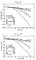
- Fig. 1shows the Ca concentrations as a function of time. A monotonic decrease of the Ca concentrations was detected in the solutions that were in contact with the alloys. The same phenomenon was observed for the reference HBSS. Until day 5 all curves were similar but after day 5 the Ti-6Al-4V 1 ⁇ m samples exhibited a higher decrease, which reaches 123 ⁇ 1.5 ppm. For both Ti-6Al-4V 4000 and Ti-Al-2.5Fe 1 ⁇ m samples the Ca concentration decreased more rapidly after day 7 attaining similar final Ca uptake concentrations, 61 ⁇ 2.3 and 63 ⁇ 1.5 ppm, respectively. All other surfaces exhibited Ca uptake values between 5 and 20 ppm.
- Fig. 2shows the P concentration as a function of time.
- the P uptake curveslike the Ca determinations, also showed a decrease as a function of time.
- the Ti-6Al-4V 4000 and 1 ⁇ m and the Ti-Al-2.5Fe 1 ⁇ mshowed the highest P uptake; 29 ⁇ 2.1, 34 ⁇ 1.5 and 58.5 ⁇ 2.2 ppm, respectively.
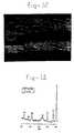
- Fig. 3shows SEM photomicrographs of the metal surfaces after immersion in HBSS. Comparing the photographs on Fig. 3 it can be seen that the precipitate layer has a plate morphology on which "globules" and/or crystals grow.
- XRMArevealed a higher quantity of Ca and P on these particles than in the plate precipitate. It was possible to observe that the plates fractured on some of the surfaces, namely Ti-6Al-4V 1200 and 1 ⁇ m, Ti-Al-2.5Fe 1 ⁇ m and stainless steel 1200. The orientation of the fractures does not seem to depend on the orientation of the grinding flaws as it is possible to observe a random cracking of the plates.
- the precipitate formed on Ti-6Al-4V 4000shows a continuous texture at the same magnification as the other observations. It was only possible to detect fractures on these surfaces, on the Ca and P rich layer, at magnifications higher than 2400 x.
- Li et al. [6]performed a series of experiments in which silica-gel was immersed in SBF. They suggest that the regulation of apatite growth is related to the Ca/P molar ratio of the fluids.
- Fugishiro et al. [1]obtained different HA morphologies by immersing Fe and Ti in Ca(edta) 2- -NaH 2 PO 4 solution. Various concentrations of Ca(edta) 2- had a direct effect on the morphology of the hydroxyapatite film.
- Fig. 4shows an AFM photomicrograph from a Ti-Al-2.5Fe 1 ⁇ m sample. It is apparent that the calcium phosphate rich coating is constituted by the agglomeration of spherical particles. Similar results were obtained for the Ti-6Al-4V 1 ⁇ m surfaces. It seems that the formation of the coating starts with heterogeneous precipitation of nuclei which gather with time until all the surface is covered.
- Fig. 5exhibits XRMA spectra acquired in a Ti-6Al-4V 4000 sample before and after immersion in HBSS.
- the calculated Ca/P ratiois 1.56 ⁇ 0.03 which indicates that the precipitate probably consists mainly of tricalcium phosphate.
- Fig. 6shows XRD spectra acquired on non-immersed (A) and immersed (B) Ti-6Al-4V 1 ⁇ m surfaces.
- Anon-immersed
- Bimmersed
- a well defined [002] peakOn the immersed samples one can observe the appearance of a well defined [002] peak and a broader peak which seems to be constituted by the junction of peaks [211] and [112] indicating the amorphous characteristics of the calcium phosphate.
- the precipitate layerhas an amorphous apatite-like structure. Similar results were obtained for the Ti-Al-2.5Fe 1 ⁇ m samples.
- Li et al. [6]monitored the development of hydroxyapatite deposits on gel-derived titania, as a function of time, after immersion in Simulated Body Fluid. In the initial stages they detected scattered precipitates all over the surface which increased in number and size until, eventually, all the surface was covered by a 10 ⁇ m coating.
- Ducheyne et al. [5]reported the formation of small deposits on titanium discs after 1-day exposure to a Simulated Physiological Solution. Two weeks of differential immersion were needed to produce an apatite layer with a thickness of 1 ⁇ m.
- the present resultsindicate that a calcium phosphate with an apatite-like structure is naturally formed on the surfaces of polished titanium alloys.
- the thickness of this layermakes it a suitable surface for bone induction. Thicknesses of at least 1 ⁇ m are needed for the calcium phosphate to show its properties and cause bone induction [5].
- the morphology of calcium phosphate precipitatesdepends on the metal substrate and its surface characteristics. It is possible to produce a naturally formed calcium phosphate coating by immersing metals such as titanium alloys and stainless steel in HBSS. Ti-6Al-4V 4000 seems to be the surface that is most favourable to produce a continuous and more adherent apatite-like coating capable of bone induction.
- EXAMPLE 2Determination of calcium phosphate depth distribution on a titanium alloy substrate using x-ray photoelectron spectroscopy
- This exampleillustrates the determination of the depth distributions of selected elements in a calcium, phosphorous and oxygen - containing coating on a titanium alloy sample using depth profiling X-ray Photoelectron Spectroscopy (XPS or ESCA).
- XPSX-ray Photoelectron Spectroscopy
- the sampleswere titanium alloy plates that had been surface treated according to the procedure of Example 1 to produce a calcium phosphate coating when immersed in calcification solutions or simulated body fluids.
- the sampleswere mounted directly to a standard XPS sample holder using a spring clip arrangement, with no pre-treatment.
- the outer coating surfacewas sufficiently electrically conducting that no electrostatic charging problems were encountered during X-ray irradiation or ion beam etching. All analysis were carried out using a Surface Science Instruments (SSI) M-probe operating at a base pressure of 3x10 -9 torr.
- SSISurface Science Instruments
- a survey spectrumwas recorded from the "as received" surface, to determine the surface composition of the coating and therefore determine the elements to be monitored for the depth profile.
- the XPS depth profilewas obtained by alternating argon ion sputtering (over an area of approx. 2 x 2 mm) and data acquisition (from an area of approx. 300 ⁇ m diameter centred in the etched crater). Elements analysed were carbon, oxygen, calcium, phosphorus, magnesium and titanium. Etch time per step was variable from 15 to 120 seconds per cycle and the etch rate was 3 nm/min using a total sputter time of 4470 seconds.
- the surface chemical composition (in atomic percent) of the "as received" coatingwas: carbon 44.9%, oxygen 33.8%, calcium 10.5%, phosphorous 8.8%, magnesium 2.0% and titanium 0% (figure 7).
- the depth profile of the coatingrevealed a gradual transition of calcium and phosphorous from the coating to the substrate, indicating the incorporation of these elements in the surface (oxide layer), and thus a chemical bonding between coating and substrate (figure 8).
- the calcium - oxygen - phosphorous layer (calcium phosphate)is estimated as being approximately 90 nm, assuming a sputter rate of 3 nm per minute as calibrated on a tantalum pentoxide film on tantalum, and that the "interface" is defined as the point where the titanium reaches approx.
- a thin layer of titanium oxideseparates the calcium phosphate layer from the titanium alloy substrate.
- the interface between the calcium phosphate and titaniumshows changes in the oxygen, phosphorous, calcium and titanium chemistries.
- the XPS peak binding energies of calcium and phosphorousdecrease at the interface with the titanium where a titanium oxide layer is found.
- An interphase regionis likely to occur at the boundary and oxygen has been depleted from the calcium phosphate to form titanium dioxide at the interface.
- Metallic titaniumis present below the interphase region. Magnesium is detected at 2 - 4 atomic percent throughout the calcium phosphate layer and increases slightly in concentration with depth towards the interface with the titanium (oxide). Carbon is found in the bulk of the titanium.
- the calcium phosphate layer that is formed on the titanium alloy substrateis chemically bound to the substrate via its surface oxide layer.
- This exampleillustrates a new two-step chemical treatment for preparing an implant with a specific surface roughness, resulting in a metallic surface that allows fast precipitation of biomimetic calcium phosphate (Ca-P) coatings from in vitro super-saturated calcification solutions (SCS).
- the specific surface roughnessresults in the following advantages: (i) the biomimetic coatings directly induced from SCS are chemically bound to metallic substrates and show higher bone-bonding ability, (ii) the coatings can be produced onto complex-shaped and/or macro-porous implants, and (iii) it is a controllable and cost-effective way to acquire Ca-P coatings.
- a newly developed two-step chemical treatmentwas performed on the metallic implant materials, i.e. commercially pure titanium (cp.Ti), annealed Ti6Al4V and porous tantalum (Ta), to produce a specific surface roughness.
- the metallic implant materialsi.e. commercially pure titanium (cp.Ti), annealed Ti6Al4V and porous tantalum (Ta)
- Tititanium
- Taporous tantalum
- FCSfast calcification solution
- HBSScommercial Hanks' balanced salt solution
- the biomimetic Ca-P coatingswere fast precipitated on the treated cp.Ti and Ti6Al4V samples by immersion in both FCS and HBSS no matter whether the Pre-Ca procedure was performed or not. But the Pre-Ca treatments could dramatically speed-up the precipitation rate of the Ca-P coatings as listed in table 2.
- FIG 9shows that a biomimetic Ca-P coating, approximately 16 ⁇ m thick, was formed on treated cp.Ti after 16 hours of immersion in FCS with Pre-Ca.
- the coatinggot thicker with immersion time as indicated by EDX (figure 10) and XRD (figure 11) results.
- the precipitation rate of the Ca-P coating in HBSSis slower than that in FCS.
- the coating from HBSS(figure 12) was much denser than that from FCS.
- the coating from HBSSmainly consisted of apatite (figure 13).
- Biomimetic Ca-P coatingscould also be precipitated on porous Ta samples (figure 14) after the treatment. The surface content change of the sample was detected by EDX as shown in figure 15.
Landscapes
- Health & Medical Sciences (AREA)
- Life Sciences & Earth Sciences (AREA)
- Chemical & Material Sciences (AREA)
- Public Health (AREA)
- Oral & Maxillofacial Surgery (AREA)
- Transplantation (AREA)
- Medicinal Chemistry (AREA)
- Animal Behavior & Ethology (AREA)
- General Health & Medical Sciences (AREA)
- Veterinary Medicine (AREA)
- Epidemiology (AREA)
- Dermatology (AREA)
- Engineering & Computer Science (AREA)
- Biomedical Technology (AREA)
- Molecular Biology (AREA)
- Inorganic Chemistry (AREA)
- Orthopedic Medicine & Surgery (AREA)
- Cardiology (AREA)
- Heart & Thoracic Surgery (AREA)
- Vascular Medicine (AREA)
- Materials For Medical Uses (AREA)
Description
- The present invention relates to an implantable device, to a process ofproducing such a device and to the biomedical use of such a device.
- US Patent 5,456,723 discloses an implant having a porous metallic surfacewhich has been treated by sandblasting and reductive acid etching resulting in a surfacemicro-roughness having a maximum peak-to-valley height of about 20 to 30 µm anda roughness spacing of about 1-5 µm. The extremely sharp, comb-like structure isnecessary in order to achieve sufficient adhesion between the implant and the coatingmaterial (hydroxyapatite) formed on it by anchoring the hydroxyapatite in the implant.
- A drawback of most hydroxyapatite-coated implants is that the anchoring ofhydroxyapatite onto the implant requires high processing temperatures, which limit thechoice of substrate materials and result in higher processing costs. The previouslypreferred technique for coating implant materials with hydroxyapatite is plasmadeposition (for a review, see P. Serekian, inHydroxylapatite Coatings in OrthopaedicSurgery, Ed. Geesink and Manley, Raven Press NY, 1993, p. 81-87). Another disadvantageof the plasma deposition technique, in addition to the high temperaturesinvolved, resides in the relatively large particle size, in the order of 30-70 µm.
- The aim of the present invention is to provide an implantable device that canbe used in a wide variety of biomedical applications (surgery, bone-replacement,prosthodontics etc.), and results in an effective bone formation and can be processed atambient temperatures.
- The aim is achieved by a shaped article suitable as an implant of a solid, i.e.non-fluid, porous or non-porous material having a surface nanoroughness with anaverage peak distance (Ra value) between 10 nm and 1,000 nm, giving rise to theformation of a composite coating when placed in solutions of bone-formingcomponents.
- The surface roughness is a critical factor of the article according to theinvention. The surface roughness is defined herein by the average peak distance, i.e theaverage spacing between protrusions on the surface (Ra value). This average peakdistance can be determined e.g. by means of Scanning Electron Microscopy (SEM). Ingeneral, the average peak distance should be 1,000 nm or less. The most suitable roughness depends on the nature of the material of the article. For articles made oftitanium, the average peak distance can be e.g. from 10 to 200 nm, for polymericmaterial, the preferred peak distance is from 20 to 500 nm, whereas for stainless steelthe peak distance is advantageously between 50 and 1,000 nm. In general, the preferredaverage peak distance range is between 2 and 500 nm.
- The depth of the surface roughness of the article is less critical than the peakdistance. However, a minimum depth is desirable, in particular a peak height - withrespect to the deepest sites on the surface - of at least 20 nm, up to about 2,000 nm.The preferred average depth is of the same order of magnitude as the average peakdistance, and is in particular from 50 nm to 1,000 nm. The average depth can also bedetermined by means of Scanning Electron Microscopy.
- The substrate of the implant article can be of various materials. These includemetals, in particular biocompatible metals such as titanium, tantalum, niobium,zirconium and alloys thereof, as well as stainless steel. Another useful class of biocompatiblematerials comprises organic natural and synthetic polymers such as polyethylene,polypropylene, polytetrafluoroethylene (Teflon®), which may also be biodegradablepolymers such as polyglycolic acid, polylactic acid or certain polysaccharides.Ceramic materials such as calcium phosphate, alumina or bioglass, as wellas composite materials, can also be used as an implant substrate. The material may beporous or non-porous. Where it is porous, the pores are distinguished from the valleysof the surface roughness by their depth: i.e. the pores have depths substantially greaterthan 2 µm, and the surface roughness may be superimposed on the pore walls.
- The substrate having the surface roughness as defined above can very efficientlybe coated with a layer of a calcium phosphate, either in vitro, or in vivo. If the calciumphosphate coating is applied in vitro, the calcium phosphate layer can be relatively thin,in the order of from a e.g. 50 nm to 200 µm, especially from 1 to 50 µm. The calciumphosphate preferably forms small crystals, producing an amorphous-like structure. Thecalcium phosphate can be any combination of calcium and phosphate ions, optionallytogether with e.g. hydroxide, chloride, sulphate, nitrate etc. anions or hydrogen, sodium,potassium, magnesium etc. cations. Preferably, the calcium phosphate is not a hydroxyapatite,since the latter tends to have too large particles.
- The calcium coating can be applied from a solution containing calcium and phosphate ions. The solution may be saturated or even super-saturated, but it may alsobe relatively diluted. This is an important advantage of the present invention since itallows the formation of a calcium phosphate coating from practically any solutioncontaining calcium and phosphate ions. The pH range of the calcium phosphate containingsolution may be between 4 and 10, preferentially between 6 and 8.
- The invention also provides a process of producing a shaped article as describedabove, comprising subjecting a solid material to a mechanical or chemical surfacetreatment until a surface roughness with the required average peak distance (Ra value)is obtained.
- The mechanical surface treatment may e.g. be a sanding or scoring treatmentusing conventional sandpaper, emery paper or glass paper having an appropriate fineness,
e.g. grade 4000, optionally in the presence of water or other fluids. Diamond pastecan also be used in the mechanical surface treatment. The surface roughening can furtherbe obtained by powder blasting, using suitable fine powders. The chemical surfacetreatment may e.g. be a treatment with a strong, preferably mineral, acid solution, suchas hydrofluoric, hydrochloric, sulphuric, nitric, perchloric acid or combinations thereof,optionally followed by oxidising agents such as nitric acid, peracids, hydroperoxides orhydrogen peroxide, optionally followed by neutralising steps. It is important that thesurface roughening is performed under controlled conditions to ensure a uniform result. - The surface-roughened implantable devices according to the invention areintended for biomedical use, i.e. as a bone substitute, a joint prosthesis, a dental implant(prosthodontics), a maxillofacial implant, a vertebral surgery aid, a transcutaneous device(stoma and the like) and other medical or cosmetic devices. Such implants can serve asa bone replacement or bone reinforcement, but also as a means of fixing a device to aparticular bone.
- The implantable devices can be provided as such, i.e. without calciumphosphate coating. Bone formation can then be induced in vivo due to the presence ofthe specific surface roughening, which can result in the formation of a calciumphosphate coating in situ. The articles can also be pre-coated with calcium phosphate,the precoat serving then to accelerate and enhance bone formation and fixation of theimplant in the target organism.
- Ti-6Al-4V and Ti-Al-2.5Fe samples, 9.15 mm and 5 mm in diameter respectively and1.5 mm thick, were used. They were ground flat in SiC papers, 1200, 4000 grit anddiamond polished down to 1 µm. 316L stainless steel samples, ca. 80 mm2, were alsoground in SiC papers, 1200 and 4000 grit. All samples were ultrasonically cleaned in90% ethanol for 20 minutes followed by a 20-minute double rinse with distilled waterand dried under a flow of hot air. The surface roughnesses were measured with a laserprofilometer (Perkin Elmer). Table 1 shows the results of the following roughnessparameters: Ra - arithmetic mean of the roughness height, Rz - mean peak-to-valleyheight and Rmax - maximum roughness depth.
- After surface polishing and cleaning, all samples were immersed in Hanks' BalancedSalt Solution (HBSS) at 37°C for 14 days in separate polyethylene containers. To allowa constant supply of solution this was changed every 48 hours. Empty polyethylenecontainers were used as reference. A sample of each retrieved solution was stored in 2mL Eppendorf™ at 4°C. Ca and P concentrations in these solutions were laterdetermined by atomic absorption spectrometry (Varian SpectAA 300) and spectrophotometry(Vitalab 21, Vitalab Scientific), respectively. All the results are the average of atleast three measurements.
- All surfaces were observed by scanning electron microscopy (Philips SEM 525M) beforeand after immersion and analysed by XRMA (Voyager XRMA, NORAN Instruments).XRD (Philips Thin-film XRD) was used to determine the structure of the precipitatelayer, and AFM was used to observe its morphology on polished titanium alloys.
- Fig. 1 shows the Ca concentrations as a function of time. A monotonic decrease of theCa concentrations was detected in the solutions that were in contact with the alloys. Thesame phenomenon was observed for the reference HBSS. Until
day 5 all curves weresimilar but afterday 5 the Ti-6Al-4V 1 µm samples exhibited a higher decrease, whichreaches 123±1.5 ppm. For both Ti-6Al-4V 4000 and Ti-Al-2.5Fe 1 µm samples theCa concentration decreased more rapidly afterday 7 attaining similar final Ca uptakeconcentrations, 61±2.3 and 63±1.5 ppm, respectively. All other surfaces exhibited Cauptake values between 5 and 20 ppm. - Fig. 2 shows the P concentration as a function of time. The P uptake curves, like the Cadeterminations, also showed a decrease as a function of time. The Ti-6Al-
4V Fe 1 µm showed the highest P uptake; 29±2.1, 34±1.5 and58.5±2.2 ppm, respectively. These findings suggest that a Ca and P rich precipitate isformed on all the surfaces from HBSS. In fact, a white film deposited on the polyethylenethat contacted with HBSS could be seen. Ti-Al-2.5Fe - Fig. 3 shows SEM photomicrographs of the metal surfaces after immersion in HBSS.Comparing the photographs on Fig. 3 it can be seen that the precipitate layer has a platemorphology on which "globules" and/or crystals grow. XRMA revealed a higherquantity of Ca and P on these particles than in the plate precipitate. It was possible toobserve that the plates fractured on some of the surfaces, namely Ti-6Al-
4V Fe 1 µm andstainless steel 1200. The orientation of the fractures doesnot seem to depend on the orientation of the grinding flaws as it is possible to observea random cracking of the plates. The precipitate formed on Ti-6Al-4V 4000 shows acontinuous texture at the same magnification as the other observations. It was onlypossible to detect fractures on these surfaces, on the Ca and P rich layer, atmagnifications higher than 2400 x. - Liet al. [6] performed a series of experiments in which silica-gel was immersed inSBF. They suggest that the regulation of apatite growth is related to the Ca/P molar ratioof the fluids. Fugishiroet al. [1] obtained different HA morphologies by immersing Feand Ti in Ca(edta)2--NaH2PO4 solution. Various concentrations of Ca(edta)2- had adirect effect on the morphology of the hydroxyapatite film.
- The SEM observations suggest that the morphology of the precipitate layer seems to bedependent both on material and surface finishing as the immersion fluid was the samein all experiments.
- Fig. 4 shows an AFM photomicrograph from a Ti-Al-2.5
Fe 1 µm sample. It is apparentthat the calcium phosphate rich coating is constituted by the agglomeration of sphericalparticles. Similar results were obtained for the Ti-6Al-4V 1 µm surfaces. It seems thatthe formation of the coating starts with heterogeneous precipitation of nuclei whichgather with time until all the surface is covered. - It was noticeable that the Ti-Al-2.5Fe alloy surfaces 4000 and 1200 did not exhibitplate precipitates. It was only possible to observe small scattered deposits which had asimilar morphology to crystals. XRMA acquisition on the flat-ground surfaces showedthe presence of no Ca or P. The same acquisition on the crystals showed the presenceof the alloy elements, Ca and P, associated with Si. Si seems to act as a nucleus for theprecipitation and growth of the crystals. This impurity is probably due to the SiC emerypaper used during the surface preparation. Either the degreasing and cleaning of thesurface was not sufficient, on these surfaces, to remove the SiC or some SiC particlesmight be anchored in the alloy's surface as Ti-Al-2.5Fe is a softer material than theother alloys.
- Fig. 5 exhibits XRMA spectra acquired in a Ti-6Al-
4V 4000 sample before and afterimmersion in HBSS. One can observe the presence of the alloy elements as well as verywell defined Ca and P peaks on the after-immersion spectra. The calculated Ca/P ratiois 1.56±0.03 which indicates that the precipitate probably consists mainly of tricalciumphosphate. - Fig. 6 shows XRD spectra acquired on non-immersed (A) and immersed (B) Ti-6Al-
4V 1 µm surfaces. On the immersed samples one can observe the appearance of a welldefined [002] peak and a broader peak which seems to be constituted by the junctionof peaks [211] and [112] indicating the amorphous characteristics of the calciumphosphate. These results suggest that the precipitate layer has an amorphous apatite-likestructure. Similar results were obtained for the Ti-Al-2.5Fe 1 µm samples. - The thickness of this layer was previously determined by SEM observations and is ca.5 µm. Liet al. [6] monitored the development of hydroxyapatite deposits on gel-derivedtitania, as a function of time, after immersion in Simulated Body Fluid. In the initialstages they detected scattered precipitates all over the surface which increased in numberand size until, eventually, all the surface was covered by a 10 µm coating. Ducheyneet al. [5] reported the formation of small deposits on titanium discs after 1-day exposureto a Simulated Physiological Solution. Two weeks of differential immersion were neededto produce an apatite layer with a thickness of 1 µm.
- Hanawaet al. [3] also reported that apatite is naturally formed on titanium whentitanium is immersed in a solution whose pH is similar to that of the bioliquid. Theyreported a thickness of 7 nm of the apatite film grown on Ti-6Al-4V which makes itimpossible for this layer to exhibit any properties of calcium phosphate in thisenvironment.
- The present results indicate that a calcium phosphate with an apatite-like structure isnaturally formed on the surfaces of polished titanium alloys. The thickness of this layermakes it a suitable surface for bone induction. Thicknesses of at least 1 µm are neededfor the calcium phosphate to show its properties and cause bone induction [5].
- The morphology of calcium phosphate precipitates depends on the metal substrate andits surface characteristics. It is possible to produce a naturally formed calcium phosphatecoating by immersing metals such as titanium alloys and stainless steel in HBSS.Ti-6Al-
4V 4000 seems to be the surface that is most favourable to produce acontinuous and more adherent apatite-like coating capable of bone induction. - This example illustrates the determination of the depth distributions of selected elementsin a calcium, phosphorous and oxygen - containing coating on a titanium alloy sampleusing depth profiling X-ray Photoelectron Spectroscopy (XPS or ESCA).
- The samples were titanium alloy plates that had been surface treated according to theprocedure of Example 1 to produce a calcium phosphate coating when immersed incalcification solutions or simulated body fluids. The samples were mounted directly toa standard XPS sample holder using a spring clip arrangement, with no pre-treatment.The outer coating surface was sufficiently electrically conducting that no electrostaticcharging problems were encountered during X-ray irradiation or ion beam etching. Allanalysis were carried out using a Surface Science Instruments (SSI) M-probe operatingat a base pressure of 3x10⁻⁹ torr.
- A survey spectrum was recorded from the "as received" surface, to determine thesurface composition of the coating and therefore determine the elements to be monitoredfor the depth profile. The XPS depth profile was obtained by alternating argon ionsputtering (over an area of approx. 2 x 2 mm) and data acquisition (from an area ofapprox. 300 µm diameter centred in the etched crater). Elements analysed were carbon,oxygen, calcium, phosphorus, magnesium and titanium. Etch time per step was variablefrom 15 to 120 seconds per cycle and the etch rate was 3 nm/min using a total sputtertime of 4470 seconds.
- The surface chemical composition (in atomic percent) of the "as received" coating was:carbon 44.9%, oxygen 33.8%, calcium 10.5%, phosphorous 8.8%, magnesium 2.0%and
titanium 0% (figure 7). The depth profile of the coating revealed a gradualtransition of calcium and phosphorous from the coating to the substrate, indicating theincorporation of these elements in the surface (oxide layer), and thus a chemical bondingbetween coating and substrate (figure 8). The calcium - oxygen - phosphorous layer(calcium phosphate) is estimated as being approximately 90 nm, assuming a sputter rateof 3 nm per minute as calibrated on a tantalum pentoxide film on tantalum, and that the"interface" is defined as the point where the titanium reaches approx. 50% of its finalvalue. A thin layer of titanium oxide separates the calcium phosphate layer from thetitanium alloy substrate. The interface between the calcium phosphate and titaniumshows changes in the oxygen, phosphorous, calcium and titanium chemistries. The XPSpeak binding energies of calcium and phosphorous decrease at the interface with thetitanium where a titanium oxide layer is found. Aninterphase region is likely to occurat the boundary and oxygen has been depleted from the calcium phosphate to formtitanium dioxide at the interface. Metallic titanium is present below the interphaseregion. Magnesium is detected at 2 - 4 atomic percent throughout the calcium phosphatelayer and increases slightly in concentration with depth towards the interface with thetitanium (oxide). Carbon is found in the bulk of the titanium. - The calcium phosphate layer that is formed on the titanium alloy substrate is chemicallybound to the substrate via its surface oxide layer.
- This example illustrates a new two-step chemical treatment for preparing an implantwith a specific surface roughness, resulting in a metallic surface that allows fastprecipitation of biomimetic calcium phosphate (Ca-P) coatings fromin vitro super-saturatedcalcification solutions (SCS). The specific surface roughness results in thefollowing advantages: (i) the biomimetic coatings directly induced from SCS arechemically bound to metallic substrates and show higher bone-bonding ability, (ii) thecoatings can be produced onto complex-shaped and/or macro-porous implants, and (iii)it is a controllable and cost-effective way to acquire Ca-P coatings.
- A newly developed two-step chemical treatment was performed on the metallic implantmaterials, i.e. commercially pure titanium (cp.Ti), annealed Ti6Al4V and poroustantalum (Ta), to produce a specific surface roughness. During this treatment, two seriesof chemical reagents were used for titanium (cp.Ti and Ti6Al4V) and tantalum implantmaterials, respectively, that resulted in the presence of the specific surface roughnessnecessary for the preparation of the coating. For the former, the samples were treatedwith a mixture of HCl and H2SO4, followed by immersion in a NaOH solution. Theporous tantalum samples were treated with a mixture of HCI, H2SO4 and HF, followedby immersion in H2O2.
- Two kinds of SCSs with different Ca and P concentrations, fast calcification solution(FCS) and commercial Hanks' balanced salt solution (HBSS), were used for preparingbiomimetic Ca-P coatings. To promote the Ca-P nucleation on the metallic surfaces,a precalcification (Pre-Ca) procedure was performed on half the treated samples beforeimmersion in the SCS. The Pre-Ca was carried out by incubating the samples in 0.5NNa2HPO4 overnight and then transferring them into saturated Ca(OH)2 for 5 h. The FCSsolution volume used for immersion was 15 ml per cm2 of sample surface area. Thesamples were immersed in sealed polystyrene vials at 37°C in a calibrated water-bath.
- Scanning electron microscopy (SEM) together with energy disperse X-ray (EDX)analyses, X-ray diffraction (XRD) and infrared (IR) spectrophotometry were used tocharacterize the obtained Ca-P coatings.
- The biomimetic Ca-P coatings were fast precipitated on the treated cp.Ti and Ti6Al4Vsamples by immersion in both FCS and HBSS no matter whether the Pre-Ca procedurewas performed or not. But the Pre-Ca treatments could dramatically speed-up theprecipitation rate of the Ca-P coatings as listed in table 2.
- Figure 9 shows that a biomimetic Ca-P coating, approximately 16 µm thick, was formedon treated cp.Ti after 16 hours of immersion in FCS with Pre-Ca. The coating gotthicker with immersion time as indicated by EDX (figure 10) and XRD (figure 11)results. The precipitation rate of the Ca-P coating in HBSS is slower than that in FCS.But the coating from HBSS (figure 12) was much denser than that from FCS. Thecoating from HBSS mainly consisted of apatite (figure 13). Biomimetic Ca-P coatings could also be precipitated on porous Ta samples (figure 14) after the treatment. Thesurface content change of the sample was detected by EDX as shown in figure 15. It isnoteworthy that no precipitation was observed on any untreated samples after 2 weeksof immersion in FCS or HBSS, even with Pre-Ca. The formation of a specific titaniumand tantalum oxide layer after their treatments is probably the main reason for theinductive precipitation of Ca-P coatings by means ofin vitro immersion in SCS. Theprocedure of the treatments for titanium implants and tantalum could not be exchanged,otherwise no Ca-P coating was acquired.
- This biomimetic calcium phosphate coating study has shown that:-
- The newly developed two-step treatment is an effective method to prepare bioactivemetallic implant surfaces allowing fast precipitation of adherent biomimetic Ca-Pcoatings byin vitro immersion in SCS. The chemical reagents needed for the treatmentof titanium implant materials and tantalum are different from each other.
- The precipitation of Ca-P coatings could be dramatically accelerated by means of precalcifyingthe treated samples before the immersions.
- The precipitation rate and composition of the Ca-P coatings can be adjusted bycontrolling the components of the SCSs (FCS or HBSS) for immersion.
Surface roughness measurements results Surface finish Ra (µm) Rz (µm) Rmax (µm) Ti-6Al- 4V 1200 grit0.47±0.01 3.74±0.04 5.13±0.08 Ti-6Al- 4V 4000 grit0.24±0.03 1.91±0.31 2.46±0.54 Ti-6Al- 4V 1 µm0.03±0.00 0.35±0.05 0.48±0.03 Ti-Al-2.5 Fe 1200 grit0.42±0.03 2.97±0.35 3.47±0.48 Ti-Al-2.5 Fe 4000 grit0.23±0.01 1.97±0.18 2.46±0.34 Ti-Al-2.5 Fe 1 µm0.04±0.01 0.28±0.11 0.36±0.19 316 L 1200 grit0.3±0.06 2.32±0.47 2.96±0.03 316 L 4000 grit0.04±0.01 0.35±0.1 0.46±0.1 List of Ca2+ and HPO42- concentrations, precipitation rate and composition of Ca-P coatings on cp.Ti and Ti6Al4V. FCS HBSS Concentration (mM) Ca2+ 3.0 1.26 HPO42- 1.87 0.78 Precipitation rate of coating No Pre-Ca 0.5 µm/ hr 1 µm/ wk Pre-Ca 1 µm/ hr 3 µm/wk Composition of coating apatite, OCP apatite - Figure 1 -
- Ca concentration as a function of time
- Figure 2 -
- P concentration as a function of time
- Figure 3 -
- SEM photomicrographs of the metal surfaces after immersion in HBSS. A:Ti-6Al-
4V 1200; B: Ti-6Al-4V 4000; C: Ti-6Al-4V 1 µm; D: Ti-Al-2.5Fe 1µm; E: Ti-Al-2.5Fe 4000; F -stainless steel 1200 - Figure 4 -
- AFM photomicrograph of a Ti-Al-2.5
Fe 1 µm sample after immersion inHBSS. Increasing magnification fromfield 0 to 3. Scanning length from field 3:1.5 µm. - Figure 5 -
- XRMA spectra acquired on a Ti-6Al-
4V 4000 sample before (A) and afterimmersion (B) in HBSS. - Figure 6 -
- XRD spectra acquired on a non-immersed (A) and immersed (B) Ti-6Al-
4V 1 µm surface - Figure 7.
- Surface chemical composition (in atomic percent) of the "as received" coating.
- Figure 8.
- Depth profile of the coating, from coating to substrate.
- Figure 9.
- Scanning electron micrograph of the Ca-P coating (CP) precipitated on cp.Ti(Ti) after 16 hours of immersion in FCS with Pre-Ca.
- Figure 10.
- EDX spectra of the cp.Ti surfaces non-treated, treated and immersed in FCSwith Pre-Ca for different hours. The shoulder of O kα peak is clearly seen afterthe treatment. The Ca and P contents increased with the increase of immersiontime.
- Figure 11.
- XRD patterns of the cp.Ti surfaces after different hours of immersion in FCSwith Pre-Ca. The counts of apatite peaks get higher with increased immersiontimes. Octa-calcium phosphate (OCP) starts to be formed at around 8 hours.
- Figure 12.
- Scanning electron micrograph of a dense Ca-P coating (CP) precipitated oncp.Ti from HBSS after 1 week of immersion with Pre-Ca. The layer betweencoating and substrate is the titanium oxide layer (OL), formed as a result of thetreatment.
- Figure 13.
- Thin-film XRD pattern of a dense Ca-P coating deposited by immersion inHBSS with Pre-Ca for 1 week.
- Figure 14.
- Scanning electron micrograph of porous tantalum (Ta) after 2 days immersionin FCS with Pre-Ca. The coating is formed throughout the porous material.
- Figure 15.
- EDX spectra of (a) non-treated, (b) treated, and (c) Pre-Ca treated, 2 dayFCS immersed porous tantalum (Ta) sample.
- 1. Y. Fujishiro, T. Sato and A. Okuwaki, "Coating of hydroxyapatite on metal platesusing thermal dissociation of calcium -EDTA chelate in phosphate solutions underhydrothermal conditions",J. Mater. Sc: Mater in Med,6, pp. 172-176, 1995
- 2. S.R. Radin and P. Ducheyne,J. Biom. Mater. Res.,,27, pp. 35, 1993
- 3. T. Hanawa, "Titanium and its oxide film: a substrate for forming apatite",in Proc.of the Bone Biomaterial Interface Workshop, Toronto, Dec. 1990, J.E. Davies ed.,Univ. Toronto Press, pp. 49-61, 1991
- 4. E. Leit
a o, M.A. Barbosa and K. de Groot, "In vitro calcification of orthopaedicimplant materials",J. Mater. Sc: Mater in Med,6, pp. 849-852, 1995 - 5. P. Ducheyne, S. Radin and K. Ishikawa, "The rate of calcium phosphateprecipitation on metal and ceramics, and the relationship to bioactivity", in BoneBonding Biomaterials, P. Ducheyne, T. Kokubo & C.A. van Blitterswijk (eds),Reed Heathcare Communications, pp. 213-218, 1992
- 6. Li, P, PhD Thesis, Leiden University (1993)
Claims (9)
- An implantable device of a material having a surface roughness with anaverage peak distance (Ra value) between 10 and 1,000 nm and an averagedepth (Rz value) between 20 and 2000 nm.
- An implantable device according to claim 1 having a surface roughnesswith an average peak distance between 20 and 500 nm.
- An implantable device according to claim 1 or 2 having a surfaceroughness with an average depth between 20 and 1,000 nm.
- An implantable device according to any one of claims 1-3, wherein thesurface is coated with a layer of a calcium phosphate having a thickness of 50nm - 100 µm, in particular of between 1000 nm and 50 µm.
- An implantable device according to any one of claims 1-4, wherein saidmaterial is a metal, a metal alloy, a ceramic material, a natural or syntheticpolymer, or a composite of any of these materials.
- A process for producing an implantable device, comprising subjecting aporous or non-porous material to a surface treatment until a surface roughnesswith an average peak distance (Ra value) between 10 and 1,000 nm and anaverage depth (Rz value) between 20 and 2,000 nm is obtained.
- A process according to claim 6, wherein said surface treatment comprisesa mechanical treatment such as a sanding or scouring step, e.g. using adiamond paste.
- A process according to claim 6, wherein said surface treatment comprisesa chemical treatment involving subjecting the surface to acidic, alkaline and/oroxidising solutions.
- Use of a device according to any one of claims 1-5, or produced accordingto any one of claims 6-8, for the manufacture of a bone substitute, a joint prosthesis, a dental implant, a maxillofacial implant, a vertebral surgery aid ora transcutaneous device.
Priority Applications (1)
| Application Number | Priority Date | Filing Date | Title |
|---|---|---|---|
| EP97201424AEP0806211B1 (en) | 1996-05-10 | 1997-05-12 | Implant material and process for producing it |
Applications Claiming Priority (3)
| Application Number | Priority Date | Filing Date | Title |
|---|---|---|---|
| EP96201293 | 1996-05-10 | ||
| EP96201293 | 1996-05-10 | ||
| EP97201424AEP0806211B1 (en) | 1996-05-10 | 1997-05-12 | Implant material and process for producing it |
Publications (2)
| Publication Number | Publication Date |
|---|---|
| EP0806211A1 EP0806211A1 (en) | 1997-11-12 |
| EP0806211B1true EP0806211B1 (en) | 2002-10-23 |
Family
ID=26142788
Family Applications (1)
| Application Number | Title | Priority Date | Filing Date |
|---|---|---|---|
| EP97201424AExpired - LifetimeEP0806211B1 (en) | 1996-05-10 | 1997-05-12 | Implant material and process for producing it |
Country Status (1)
| Country | Link |
|---|---|
| EP (1) | EP0806211B1 (en) |
Cited By (41)
| Publication number | Priority date | Publication date | Assignee | Title |
|---|---|---|---|---|
| US7763270B2 (en) | 2002-09-10 | 2010-07-27 | Scil Technology Gmbh | Metal implant coated under reduced oxygen concentration with osteoinductive protein |
| EP1477141B2 (en)† | 2003-05-16 | 2010-12-08 | Implant Innovations, Inc. | Surface treatment process for implants made of titanium alloy |
| US7931683B2 (en) | 2007-07-27 | 2011-04-26 | Boston Scientific Scimed, Inc. | Articles having ceramic coated surfaces |
| US7938855B2 (en) | 2007-11-02 | 2011-05-10 | Boston Scientific Scimed, Inc. | Deformable underlayer for stent |
| US7942926B2 (en) | 2007-07-11 | 2011-05-17 | Boston Scientific Scimed, Inc. | Endoprosthesis coating |
| US7976915B2 (en) | 2007-05-23 | 2011-07-12 | Boston Scientific Scimed, Inc. | Endoprosthesis with select ceramic morphology |
| US7981150B2 (en) | 2006-11-09 | 2011-07-19 | Boston Scientific Scimed, Inc. | Endoprosthesis with coatings |
| US8002823B2 (en) | 2007-07-11 | 2011-08-23 | Boston Scientific Scimed, Inc. | Endoprosthesis coating |
| US8029554B2 (en) | 2007-11-02 | 2011-10-04 | Boston Scientific Scimed, Inc. | Stent with embedded material |
| US8067054B2 (en) | 2007-04-05 | 2011-11-29 | Boston Scientific Scimed, Inc. | Stents with ceramic drug reservoir layer and methods of making and using the same |
| US8066763B2 (en) | 1998-04-11 | 2011-11-29 | Boston Scientific Scimed, Inc. | Drug-releasing stent with ceramic-containing layer |
| US8071156B2 (en) | 2009-03-04 | 2011-12-06 | Boston Scientific Scimed, Inc. | Endoprostheses |
| US8070797B2 (en) | 2007-03-01 | 2011-12-06 | Boston Scientific Scimed, Inc. | Medical device with a porous surface for delivery of a therapeutic agent |
| US8075312B2 (en) | 2005-08-30 | 2011-12-13 | Zimmer Dental, Inc. | Dental implant with improved osseointegration features |
| US8187620B2 (en) | 2006-03-27 | 2012-05-29 | Boston Scientific Scimed, Inc. | Medical devices comprising a porous metal oxide or metal material and a polymer coating for delivering therapeutic agents |
| US8216632B2 (en) | 2007-11-02 | 2012-07-10 | Boston Scientific Scimed, Inc. | Endoprosthesis coating |
| US8221822B2 (en) | 2007-07-31 | 2012-07-17 | Boston Scientific Scimed, Inc. | Medical device coating by laser cladding |
| US8231980B2 (en) | 2008-12-03 | 2012-07-31 | Boston Scientific Scimed, Inc. | Medical implants including iridium oxide |
| US8231387B2 (en) | 2008-07-02 | 2012-07-31 | Zimmer, Inc. | Porous implant with non-porous threads |
| US8287937B2 (en) | 2009-04-24 | 2012-10-16 | Boston Scientific Scimed, Inc. | Endoprosthese |
| US8353949B2 (en) | 2006-09-14 | 2013-01-15 | Boston Scientific Scimed, Inc. | Medical devices with drug-eluting coating |
| US8372419B2 (en) | 2004-03-10 | 2013-02-12 | Scil Technology Gmbh | Coated implants, their manufacturing and use thereof |
| US8431149B2 (en) | 2007-03-01 | 2013-04-30 | Boston Scientific Scimed, Inc. | Coated medical devices for abluminal drug delivery |
| US8449603B2 (en) | 2008-06-18 | 2013-05-28 | Boston Scientific Scimed, Inc. | Endoprosthesis coating |
| US8546334B2 (en) | 2001-11-19 | 2013-10-01 | Scil Technology Gmbh | Device having osteoinductive and osteoconductive properties |
| US8562346B2 (en) | 2005-08-30 | 2013-10-22 | Zimmer Dental, Inc. | Dental implant for a jaw with reduced bone volume and improved osseointegration features |
| US8562348B2 (en) | 2008-07-02 | 2013-10-22 | Zimmer Dental, Inc. | Modular implant with secured porous portion |
| US8574615B2 (en) | 2006-03-24 | 2013-11-05 | Boston Scientific Scimed, Inc. | Medical devices having nanoporous coatings for controlled therapeutic agent delivery |
| US8602782B2 (en) | 2009-11-24 | 2013-12-10 | Zimmer Dental, Inc. | Porous implant device with improved core |
| US8632836B2 (en) | 2007-07-09 | 2014-01-21 | Astra Tech Ab | Nanosurface |
| US8771343B2 (en) | 2006-06-29 | 2014-07-08 | Boston Scientific Scimed, Inc. | Medical devices with selective titanium oxide coatings |
| US8815273B2 (en) | 2007-07-27 | 2014-08-26 | Boston Scientific Scimed, Inc. | Drug eluting medical devices having porous layers |
| US8814567B2 (en) | 2005-05-26 | 2014-08-26 | Zimmer Dental, Inc. | Dental implant prosthetic device with improved osseointegration and esthetic features |
| US8815275B2 (en) | 2006-06-28 | 2014-08-26 | Boston Scientific Scimed, Inc. | Coatings for medical devices comprising a therapeutic agent and a metallic material |
| US8900292B2 (en) | 2007-08-03 | 2014-12-02 | Boston Scientific Scimed, Inc. | Coating for medical device having increased surface area |
| US8899982B2 (en) | 2008-07-02 | 2014-12-02 | Zimmer Dental, Inc. | Implant with structure for securing a porous portion |
| US8920491B2 (en) | 2008-04-22 | 2014-12-30 | Boston Scientific Scimed, Inc. | Medical devices having a coating of inorganic material |
| US8932346B2 (en) | 2008-04-24 | 2015-01-13 | Boston Scientific Scimed, Inc. | Medical devices having inorganic particle layers |
| US9095396B2 (en) | 2008-07-02 | 2015-08-04 | Zimmer Dental, Inc. | Porous implant with non-porous threads |
| US9149345B2 (en) | 2007-08-30 | 2015-10-06 | Zimmer Dental, Inc. | Multiple root implant |
| US9284409B2 (en) | 2007-07-19 | 2016-03-15 | Boston Scientific Scimed, Inc. | Endoprosthesis having a non-fouling surface |
Families Citing this family (10)
| Publication number | Priority date | Publication date | Assignee | Title |
|---|---|---|---|---|
| SE9900189D0 (en)* | 1999-01-22 | 1999-01-22 | Astra Ab | Implant |
| CH694935A5 (en)* | 2000-07-26 | 2005-09-30 | Straumann Holding Ag | Oberflaechenmodifizierte implants. |
| JP2002322013A (en)* | 2001-04-25 | 2002-11-08 | Univ Nagoya | Active substance precursor, active substance using the precursor, and method for producing the active substance |
| WO2008082698A2 (en)* | 2006-12-28 | 2008-07-10 | Boston Scientific Limited | Medical devices and methods of making the same |
| ITTO20070719A1 (en) | 2007-10-12 | 2009-04-13 | Torino Politecnico | MULTIFUNCTIONAL TITANIUM SURFACES FOR OSTEOINTEGRATION. |
| US20100114314A1 (en) | 2008-11-06 | 2010-05-06 | Matthew Lomicka | Expandable bone implant |
| US9707058B2 (en) | 2009-07-10 | 2017-07-18 | Zimmer Dental, Inc. | Patient-specific implants with improved osseointegration |
| EP3034033A1 (en) | 2014-12-16 | 2016-06-22 | Nobel Biocare Services AG | Dental implant |
| EP3473277A1 (en)* | 2017-10-20 | 2019-04-24 | Paul Scherrer Institut | Method for biomimetic growth of calcium phosphates ceramics on metal implants |
| CA3119714A1 (en) | 2018-11-12 | 2020-05-22 | Nobel Biocare Services Ag | Dental implant or component having a protective layer |
Family Cites Families (6)
| Publication number | Priority date | Publication date | Assignee | Title |
|---|---|---|---|---|
| SE416175B (en)* | 1979-03-07 | 1980-12-08 | Per Ingvar Branemark | FOR IMPLANTATION IN BODY TISSUE Separate Bone Tissue, Dedicated Material |
| US5344457A (en)* | 1986-05-19 | 1994-09-06 | The University Of Toronto Innovations Foundation | Porous surfaced implant |
| EP0388576B1 (en)* | 1989-03-23 | 1993-09-15 | Institut Straumann Ag | Metallic implant |
| US5164187A (en)* | 1990-04-05 | 1992-11-17 | Norian Corporation | Hydroxyapatite prosthesis coatings |
| NL9301941A (en)* | 1993-11-09 | 1995-06-01 | Klaas De Groot | Method of applying a coating of a bioactive material to implants. |
| US5607480A (en)* | 1993-11-10 | 1997-03-04 | Implant Innovations, Inc. | Surgically implantable prosthetic devices |
- 1997
- 1997-05-12EPEP97201424Apatent/EP0806211B1/ennot_activeExpired - Lifetime
Cited By (49)
| Publication number | Priority date | Publication date | Assignee | Title |
|---|---|---|---|---|
| US8066763B2 (en) | 1998-04-11 | 2011-11-29 | Boston Scientific Scimed, Inc. | Drug-releasing stent with ceramic-containing layer |
| US8546334B2 (en) | 2001-11-19 | 2013-10-01 | Scil Technology Gmbh | Device having osteoinductive and osteoconductive properties |
| US7763270B2 (en) | 2002-09-10 | 2010-07-27 | Scil Technology Gmbh | Metal implant coated under reduced oxygen concentration with osteoinductive protein |
| US8257728B2 (en) | 2002-09-10 | 2012-09-04 | Scil Technology Gmbh | Metal implant coated under reduced oxygen concentration with osteoinductive protein |
| EP1477141B2 (en)† | 2003-05-16 | 2010-12-08 | Implant Innovations, Inc. | Surface treatment process for implants made of titanium alloy |
| US11015253B2 (en) | 2003-05-16 | 2021-05-25 | Biomet 3I, Llc | Surface treatment process for implants made of titanium alloy |
| US10227697B2 (en) | 2003-05-16 | 2019-03-12 | Biomet 3I, Llc | Surface treatment process for implants made of titanium alloy |
| US8251700B2 (en) | 2003-05-16 | 2012-08-28 | Biomet 3I, Llc | Surface treatment process for implants made of titanium alloy |
| US8372419B2 (en) | 2004-03-10 | 2013-02-12 | Scil Technology Gmbh | Coated implants, their manufacturing and use thereof |
| US8814567B2 (en) | 2005-05-26 | 2014-08-26 | Zimmer Dental, Inc. | Dental implant prosthetic device with improved osseointegration and esthetic features |
| US8075312B2 (en) | 2005-08-30 | 2011-12-13 | Zimmer Dental, Inc. | Dental implant with improved osseointegration features |
| US8562346B2 (en) | 2005-08-30 | 2013-10-22 | Zimmer Dental, Inc. | Dental implant for a jaw with reduced bone volume and improved osseointegration features |
| US8574615B2 (en) | 2006-03-24 | 2013-11-05 | Boston Scientific Scimed, Inc. | Medical devices having nanoporous coatings for controlled therapeutic agent delivery |
| US8187620B2 (en) | 2006-03-27 | 2012-05-29 | Boston Scientific Scimed, Inc. | Medical devices comprising a porous metal oxide or metal material and a polymer coating for delivering therapeutic agents |
| US8815275B2 (en) | 2006-06-28 | 2014-08-26 | Boston Scientific Scimed, Inc. | Coatings for medical devices comprising a therapeutic agent and a metallic material |
| US8771343B2 (en) | 2006-06-29 | 2014-07-08 | Boston Scientific Scimed, Inc. | Medical devices with selective titanium oxide coatings |
| US8353949B2 (en) | 2006-09-14 | 2013-01-15 | Boston Scientific Scimed, Inc. | Medical devices with drug-eluting coating |
| US7981150B2 (en) | 2006-11-09 | 2011-07-19 | Boston Scientific Scimed, Inc. | Endoprosthesis with coatings |
| US8431149B2 (en) | 2007-03-01 | 2013-04-30 | Boston Scientific Scimed, Inc. | Coated medical devices for abluminal drug delivery |
| US8070797B2 (en) | 2007-03-01 | 2011-12-06 | Boston Scientific Scimed, Inc. | Medical device with a porous surface for delivery of a therapeutic agent |
| US8067054B2 (en) | 2007-04-05 | 2011-11-29 | Boston Scientific Scimed, Inc. | Stents with ceramic drug reservoir layer and methods of making and using the same |
| US7976915B2 (en) | 2007-05-23 | 2011-07-12 | Boston Scientific Scimed, Inc. | Endoprosthesis with select ceramic morphology |
| US8632836B2 (en) | 2007-07-09 | 2014-01-21 | Astra Tech Ab | Nanosurface |
| US9642708B2 (en) | 2007-07-09 | 2017-05-09 | Astra Tech Ab | Nanosurface |
| US8002823B2 (en) | 2007-07-11 | 2011-08-23 | Boston Scientific Scimed, Inc. | Endoprosthesis coating |
| US7942926B2 (en) | 2007-07-11 | 2011-05-17 | Boston Scientific Scimed, Inc. | Endoprosthesis coating |
| US9284409B2 (en) | 2007-07-19 | 2016-03-15 | Boston Scientific Scimed, Inc. | Endoprosthesis having a non-fouling surface |
| US7931683B2 (en) | 2007-07-27 | 2011-04-26 | Boston Scientific Scimed, Inc. | Articles having ceramic coated surfaces |
| US8815273B2 (en) | 2007-07-27 | 2014-08-26 | Boston Scientific Scimed, Inc. | Drug eluting medical devices having porous layers |
| US8221822B2 (en) | 2007-07-31 | 2012-07-17 | Boston Scientific Scimed, Inc. | Medical device coating by laser cladding |
| US8900292B2 (en) | 2007-08-03 | 2014-12-02 | Boston Scientific Scimed, Inc. | Coating for medical device having increased surface area |
| US9149345B2 (en) | 2007-08-30 | 2015-10-06 | Zimmer Dental, Inc. | Multiple root implant |
| US7938855B2 (en) | 2007-11-02 | 2011-05-10 | Boston Scientific Scimed, Inc. | Deformable underlayer for stent |
| US8029554B2 (en) | 2007-11-02 | 2011-10-04 | Boston Scientific Scimed, Inc. | Stent with embedded material |
| US8216632B2 (en) | 2007-11-02 | 2012-07-10 | Boston Scientific Scimed, Inc. | Endoprosthesis coating |
| US8920491B2 (en) | 2008-04-22 | 2014-12-30 | Boston Scientific Scimed, Inc. | Medical devices having a coating of inorganic material |
| US8932346B2 (en) | 2008-04-24 | 2015-01-13 | Boston Scientific Scimed, Inc. | Medical devices having inorganic particle layers |
| US8449603B2 (en) | 2008-06-18 | 2013-05-28 | Boston Scientific Scimed, Inc. | Endoprosthesis coating |
| US9095396B2 (en) | 2008-07-02 | 2015-08-04 | Zimmer Dental, Inc. | Porous implant with non-porous threads |
| US8899982B2 (en) | 2008-07-02 | 2014-12-02 | Zimmer Dental, Inc. | Implant with structure for securing a porous portion |
| US8231387B2 (en) | 2008-07-02 | 2012-07-31 | Zimmer, Inc. | Porous implant with non-porous threads |
| US8562348B2 (en) | 2008-07-02 | 2013-10-22 | Zimmer Dental, Inc. | Modular implant with secured porous portion |
| US8231980B2 (en) | 2008-12-03 | 2012-07-31 | Boston Scientific Scimed, Inc. | Medical implants including iridium oxide |
| US8071156B2 (en) | 2009-03-04 | 2011-12-06 | Boston Scientific Scimed, Inc. | Endoprostheses |
| US8287937B2 (en) | 2009-04-24 | 2012-10-16 | Boston Scientific Scimed, Inc. | Endoprosthese |
| US8602782B2 (en) | 2009-11-24 | 2013-12-10 | Zimmer Dental, Inc. | Porous implant device with improved core |
| US9439738B2 (en) | 2009-11-24 | 2016-09-13 | Zimmer Dental, Inc. | Porous implant device with improved core |
| US9901424B2 (en) | 2009-11-24 | 2018-02-27 | Zimmer Dental, Inc. | Porous implant device with improved core |
| US10687919B2 (en) | 2009-11-24 | 2020-06-23 | Zimmer Dental, Inc. | Porous implant device with improved core |
Also Published As
| Publication number | Publication date |
|---|---|
| EP0806211A1 (en) | 1997-11-12 |
Similar Documents
| Publication | Publication Date | Title |
|---|---|---|
| EP0806211B1 (en) | Implant material and process for producing it | |
| US6146686A (en) | Implant material and process for using it | |
| EP0806212B1 (en) | Device for incorporation and release of biologically active agents | |
| US6143948A (en) | Device for incorporation and release of biologically active agents | |
| Wen et al. | Preparation of calcium phosphate coatings on titanium implant materials by simple chemistry | |
| US6569489B1 (en) | Bioactive ceramic coating and method | |
| Wen et al. | Fast precipitation of calcium phosphate layers on titanium induced by simple chemical treatments | |
| Zhang et al. | A comparative study of electrochemical deposition and biomimetic deposition of calcium phosphate on porous titanium | |
| AU2003203220B2 (en) | Surface mineralized spinal implants | |
| Wen et al. | Preparation of bioactive microporous titanium surface by a new two-step chemical treatment | |
| Pierre et al. | Calcium phosphate coatings elaborated by the soaking process on titanium dental implants: Surface preparation, processing and physical–chemical characterization | |
| Kang et al. | State of the art of bioimplants manufacturing: part II | |
| Kim et al. | In vitro dissolution and mechanical behavior of c-axis preferentially oriented hydroxyapatite thin films fabricated by pulsed laser deposition | |
| US7767250B2 (en) | Bioceramic coating of a metal-containing substrate | |
| JPH08299429A (en) | Method for surface treatment of titanium implant and bio-compatible titanium implant | |
| Shi et al. | Biomimetic apatite layers on plasma-sprayed titanium coatings after surface modification | |
| Sandrini et al. | A novel biomimetic treatment for an improved osteointegration of titanium | |
| Kolafová et al. | In Vitro Bioactivity Test of Real Dental Implants According to ISO 23317. | |
| Grubova et al. | Sand-blasting treatment as a way to improve the adhesion strength of hydroxyapatite coating on titanium implant | |
| Leitao et al. | Influence of substrate material and surface finishing on the morphology of the calcium‐phosphate coating | |
| KR20100076867A (en) | Etching and biocompatible thin film coated methods for surface of implant | |
| Salemi et al. | Biomimetic synthesis of calcium phosphate materials on alkaline-treated titanium | |
| Barrere et al. | Physical and chemical characteristics of plasma-sprayed and biomimetic apatite coating | |
| Victoria Cabanas | Bioceramic coatings for medical implants | |
| Layrolle¹ et al. | Biomimetic hydroxyapatite coating on Ti6Al4V induced by pre-calcification |
Legal Events
| Date | Code | Title | Description |
|---|---|---|---|
| PUAI | Public reference made under article 153(3) epc to a published international application that has entered the european phase | Free format text:ORIGINAL CODE: 0009012 | |
| AK | Designated contracting states | Kind code of ref document:A1 Designated state(s):AT BE CH DE DK ES FI FR GB GR IE IT LI NL PT SE | |
| 17P | Request for examination filed | Effective date:19980127 | |
| RAP1 | Party data changed (applicant data changed or rights of an application transferred) | Owner name:ISOTIS N.V. | |
| 17Q | First examination report despatched | Effective date:20010410 | |
| GRAG | Despatch of communication of intention to grant | Free format text:ORIGINAL CODE: EPIDOS AGRA | |
| GRAG | Despatch of communication of intention to grant | Free format text:ORIGINAL CODE: EPIDOS AGRA | |
| GRAH | Despatch of communication of intention to grant a patent | Free format text:ORIGINAL CODE: EPIDOS IGRA | |
| GRAH | Despatch of communication of intention to grant a patent | Free format text:ORIGINAL CODE: EPIDOS IGRA | |
| GRAA | (expected) grant | Free format text:ORIGINAL CODE: 0009210 | |
| AK | Designated contracting states | Kind code of ref document:B1 Designated state(s):AT BE CH DE DK ES FI FR GB GR IE IT LI NL PT SE | |
| PG25 | Lapsed in a contracting state [announced via postgrant information from national office to epo] | Ref country code:LI Free format text:LAPSE BECAUSE OF FAILURE TO SUBMIT A TRANSLATION OF THE DESCRIPTION OR TO PAY THE FEE WITHIN THE PRESCRIBED TIME-LIMIT Effective date:20021023 Ref country code:GR Free format text:LAPSE BECAUSE OF FAILURE TO SUBMIT A TRANSLATION OF THE DESCRIPTION OR TO PAY THE FEE WITHIN THE PRESCRIBED TIME-LIMIT Effective date:20021023 Ref country code:FI Free format text:LAPSE BECAUSE OF FAILURE TO SUBMIT A TRANSLATION OF THE DESCRIPTION OR TO PAY THE FEE WITHIN THE PRESCRIBED TIME-LIMIT Effective date:20021023 Ref country code:CH Free format text:LAPSE BECAUSE OF FAILURE TO SUBMIT A TRANSLATION OF THE DESCRIPTION OR TO PAY THE FEE WITHIN THE PRESCRIBED TIME-LIMIT Effective date:20021023 Ref country code:AT Free format text:LAPSE BECAUSE OF FAILURE TO SUBMIT A TRANSLATION OF THE DESCRIPTION OR TO PAY THE FEE WITHIN THE PRESCRIBED TIME-LIMIT Effective date:20021023 | |
| REF | Corresponds to: | Ref document number:226453 Country of ref document:AT Date of ref document:20021115 Kind code of ref document:T | |
| REG | Reference to a national code | Ref country code:GB Ref legal event code:FG4D | |
| REG | Reference to a national code | Ref country code:CH Ref legal event code:EP | |
| REG | Reference to a national code | Ref country code:IE Ref legal event code:FG4D | |
| REF | Corresponds to: | Ref document number:69716505 Country of ref document:DE Date of ref document:20021128 | |
| PG25 | Lapsed in a contracting state [announced via postgrant information from national office to epo] | Ref country code:SE Free format text:LAPSE BECAUSE OF FAILURE TO SUBMIT A TRANSLATION OF THE DESCRIPTION OR TO PAY THE FEE WITHIN THE PRESCRIBED TIME-LIMIT Effective date:20030123 Ref country code:PT Free format text:LAPSE BECAUSE OF FAILURE TO SUBMIT A TRANSLATION OF THE DESCRIPTION OR TO PAY THE FEE WITHIN THE PRESCRIBED TIME-LIMIT Effective date:20030123 Ref country code:DK Free format text:LAPSE BECAUSE OF FAILURE TO SUBMIT A TRANSLATION OF THE DESCRIPTION OR TO PAY THE FEE WITHIN THE PRESCRIBED TIME-LIMIT Effective date:20030123 | |
| REG | Reference to a national code | Ref country code:ES Ref legal event code:FG2A Ref document number:2185861 Country of ref document:ES Kind code of ref document:T3 | |
| REG | Reference to a national code | Ref country code:CH Ref legal event code:PL | |
| ET | Fr: translation filed | ||
| PLBE | No opposition filed within time limit | Free format text:ORIGINAL CODE: 0009261 | |
| STAA | Information on the status of an ep patent application or granted ep patent | Free format text:STATUS: NO OPPOSITION FILED WITHIN TIME LIMIT | |
| 26N | No opposition filed | Effective date:20030724 | |
| PGFP | Annual fee paid to national office [announced via postgrant information from national office to epo] | Ref country code:IE Payment date:20040511 Year of fee payment:8 | |
| PGFP | Annual fee paid to national office [announced via postgrant information from national office to epo] | Ref country code:NL Payment date:20040517 Year of fee payment:8 | |
| PGFP | Annual fee paid to national office [announced via postgrant information from national office to epo] | Ref country code:ES Payment date:20040526 Year of fee payment:8 | |
| PGFP | Annual fee paid to national office [announced via postgrant information from national office to epo] | Ref country code:BE Payment date:20040622 Year of fee payment:8 | |
| PG25 | Lapsed in a contracting state [announced via postgrant information from national office to epo] | Ref country code:IT Free format text:LAPSE BECAUSE OF NON-PAYMENT OF DUE FEES;WARNING: LAPSES OF ITALIAN PATENTS WITH EFFECTIVE DATE BEFORE 2007 MAY HAVE OCCURRED AT ANY TIME BEFORE 2007. THE CORRECT EFFECTIVE DATE MAY BE DIFFERENT FROM THE ONE RECORDED. Effective date:20050512 Ref country code:IE Free format text:LAPSE BECAUSE OF NON-PAYMENT OF DUE FEES Effective date:20050512 | |
| PG25 | Lapsed in a contracting state [announced via postgrant information from national office to epo] | Ref country code:ES Free format text:LAPSE BECAUSE OF NON-PAYMENT OF DUE FEES Effective date:20050513 | |
| PG25 | Lapsed in a contracting state [announced via postgrant information from national office to epo] | Ref country code:BE Free format text:LAPSE BECAUSE OF NON-PAYMENT OF DUE FEES Effective date:20050531 | |
| BERE | Be: lapsed | Owner name:*ISOTIS N.V. Effective date:20050531 | |
| PG25 | Lapsed in a contracting state [announced via postgrant information from national office to epo] | Ref country code:NL Free format text:LAPSE BECAUSE OF NON-PAYMENT OF DUE FEES Effective date:20051201 | |
| NLV4 | Nl: lapsed or anulled due to non-payment of the annual fee | Effective date:20051201 | |
| REG | Reference to a national code | Ref country code:IE Ref legal event code:MM4A | |
| REG | Reference to a national code | Ref country code:ES Ref legal event code:FD2A Effective date:20050513 | |
| BERE | Be: lapsed | Owner name:*ISOTIS N.V. Effective date:20050531 | |
| PGFP | Annual fee paid to national office [announced via postgrant information from national office to epo] | Ref country code:DE Payment date:20080611 Year of fee payment:12 | |
| REG | Reference to a national code | Ref country code:FR Ref legal event code:TP | |
| PGFP | Annual fee paid to national office [announced via postgrant information from national office to epo] | Ref country code:FR Payment date:20080530 Year of fee payment:12 | |
| PGFP | Annual fee paid to national office [announced via postgrant information from national office to epo] | Ref country code:GB Payment date:20080530 Year of fee payment:12 | |
| GBPC | Gb: european patent ceased through non-payment of renewal fee | Effective date:20090512 | |
| REG | Reference to a national code | Ref country code:FR Ref legal event code:ST Effective date:20100129 | |
| PG25 | Lapsed in a contracting state [announced via postgrant information from national office to epo] | Ref country code:FR Free format text:LAPSE BECAUSE OF NON-PAYMENT OF DUE FEES Effective date:20090602 | |
| PG25 | Lapsed in a contracting state [announced via postgrant information from national office to epo] | Ref country code:GB Free format text:LAPSE BECAUSE OF NON-PAYMENT OF DUE FEES Effective date:20090512 | |
| PG25 | Lapsed in a contracting state [announced via postgrant information from national office to epo] | Ref country code:DE Free format text:LAPSE BECAUSE OF NON-PAYMENT OF DUE FEES Effective date:20091201 |