EP0806020B1 - Colour detection apparatus - Google Patents
Colour detection apparatusDownload PDFInfo
- Publication number
- EP0806020B1 EP0806020B1EP96900629AEP96900629AEP0806020B1EP 0806020 B1EP0806020 B1EP 0806020B1EP 96900629 AEP96900629 AEP 96900629AEP 96900629 AEP96900629 AEP 96900629AEP 0806020 B1EP0806020 B1EP 0806020B1
- Authority
- EP
- European Patent Office
- Prior art keywords
- colour
- article
- articles
- read
- detected
- Prior art date
- Legal status (The legal status is an assumption and is not a legal conclusion. Google has not performed a legal analysis and makes no representation as to the accuracy of the status listed.)
- Expired - Lifetime
Links
- 238000001514detection methodMethods0.000titleclaimsdescription18
- 238000001228spectrumMethods0.000claimsabstractdescription36
- 239000003086colorantSubstances0.000claimsabstractdescription17
- 238000000034methodMethods0.000claimsabstractdescription14
- 238000001429visible spectrumMethods0.000claimsdescription13
- 208000001613GamblingDiseases0.000claimsdescription11
- 239000000428dustSubstances0.000claimsdescription6
- 230000001419dependent effectEffects0.000claims3
- 230000007723transport mechanismEffects0.000abstract2
- 238000004519manufacturing processMethods0.000description2
- 238000005259measurementMethods0.000description2
- 239000004677NylonSubstances0.000description1
- 230000009977dual effectEffects0.000description1
- 238000005562fadingMethods0.000description1
- 239000007789gasSubstances0.000description1
- 229920001778nylonPolymers0.000description1
- 238000003908quality control methodMethods0.000description1
- 238000011896sensitive detectionMethods0.000description1
- 230000035945sensitivityEffects0.000description1
Images


Classifications
- G—PHYSICS
- G01—MEASURING; TESTING
- G01N—INVESTIGATING OR ANALYSING MATERIALS BY DETERMINING THEIR CHEMICAL OR PHYSICAL PROPERTIES
- G01N21/00—Investigating or analysing materials by the use of optical means, i.e. using sub-millimetre waves, infrared, visible or ultraviolet light
- G01N21/17—Systems in which incident light is modified in accordance with the properties of the material investigated
- G01N21/25—Colour; Spectral properties, i.e. comparison of effect of material on the light at two or more different wavelengths or wavelength bands
- G01N21/251—Colorimeters; Construction thereof
- B—PERFORMING OPERATIONS; TRANSPORTING
- B07—SEPARATING SOLIDS FROM SOLIDS; SORTING
- B07C—POSTAL SORTING; SORTING INDIVIDUAL ARTICLES, OR BULK MATERIAL FIT TO BE SORTED PIECE-MEAL, e.g. BY PICKING
- B07C5/00—Sorting according to a characteristic or feature of the articles or material being sorted, e.g. by control effected by devices which detect or measure such characteristic or feature; Sorting by manually actuated devices, e.g. switches
- B07C5/34—Sorting according to other particular properties
- B07C5/342—Sorting according to other particular properties according to optical properties, e.g. colour
- G—PHYSICS
- G07—CHECKING-DEVICES
- G07D—HANDLING OF COINS OR VALUABLE PAPERS, e.g. TESTING, SORTING BY DENOMINATIONS, COUNTING, DISPENSING, CHANGING OR DEPOSITING
- G07D3/00—Sorting a mixed bulk of coins into denominations
- G07D3/14—Apparatus driven under control of coin-sensing elements
- G—PHYSICS
- G07—CHECKING-DEVICES
- G07F—COIN-FREED OR LIKE APPARATUS
- G07F1/00—Coin inlet arrangements; Coins specially adapted to operate coin-freed mechanisms
- G07F1/06—Coins specially adapted to operate coin-freed mechanisms
- Y—GENERAL TAGGING OF NEW TECHNOLOGICAL DEVELOPMENTS; GENERAL TAGGING OF CROSS-SECTIONAL TECHNOLOGIES SPANNING OVER SEVERAL SECTIONS OF THE IPC; TECHNICAL SUBJECTS COVERED BY FORMER USPC CROSS-REFERENCE ART COLLECTIONS [XRACs] AND DIGESTS
- Y10—TECHNICAL SUBJECTS COVERED BY FORMER USPC
- Y10S—TECHNICAL SUBJECTS COVERED BY FORMER USPC CROSS-REFERENCE ART COLLECTIONS [XRACs] AND DIGESTS
- Y10S209/00—Classifying, separating, and assorting solids
- Y10S209/938—Illuminating means facilitating visual inspection
Definitions
- This inventionconcerns colour detection apparatus, particularly but not exclusively apparatus for sorting different coloured articles, and especially apparatus for sorting different coloured gambling chips.
- Prior arrangements for automatically sorting coloured gambling chipshave generally used a plurality of photocells, usually three cells each having a respective filter to detect respectively red, yellow and green light. This arrangement is relatively unsophisticated and problems can occur in detecting different coloured chips and especially relatively similar colours. Particular difficulties can also be encountered when some chips of a particular colour have become faded and/or dirty relative to other chips due perhaps to the chips being of different ages. Colour variations can also occur between different batches of a particular colour chip. Further difficulties have also been experienced with chips with different coloured faces on each side, or chips bearing ordered or random patterns.
- EPA 424355discloses an apparatus for sorting gambling chips. This comprises a television set and apparatus which compares colour data of a chip detected by three CCD sensors each being provided with a colour filter with a colour data of sample chips. The chips are therefore sorted according to a measured colour.
- thismay include an article of more than one colour and/or one which bears a pattern.
- colour detection apparatuscomprising means for detecting light intensity substantially across the visible spectrum and means for comparing the read light intensity relative to a previously read light intensity substantially across the visible spectrum, means being provided for splitting the light into one or more spectra.
- Meansare preferably provided for comparing the read light intensity with previously read light intensities for one or more known colours.
- Meansare preferably provided for reading the light intensity at a plurality of closely spaced intervals across the visible spectrum and preferably substantially sixty four spaced intervals.
- Diffraction meansmay be provided for splitting the light into one or more spectra, and desirably a diffraction grid is provided. Means are preferably provided for focusing light onto the diffraction grid.
- the apparatusis preferably arranged to read the light intensity across respective parts of adjacent spectra, desirably with the red end of a one spectra being read along with the blue end of a larger spectra.
- the apparatusmay comprise a visible detector capable of measuring light intensity at a plurality of closely spaced intervals, for measuring the respective light intensities across the spectrum or the respective parts of each spectra.
- the inventionalso provides apparatus for detecting the colour of an article, the apparatus comprising colour detection apparatus according to any of the preceding six paragraphs.
- the apparatuspreferably comprises means for shining light onto the article.
- the apparatusis preferably arranged such that the colour is read for at least part of the article.
- the detection apparatusmay be arranged to record the colour detected, i.e. the intensity and frequency, and the positioning of the article, so as to detect changes in colour and/or pattern across the article.
- the apparatuspreferably comprises means for differentiating the colour detected relative to the position on the article so as to indicate colour changes.
- the apparatuspreferably also comprises means for comparing the colour detected with a plurality of previous colour detections of articles, with the articles at different orientations.
- the apparatusmay also be arranged to include the detected colour of an article in subsequent comparisons, whereby to update the apparatus.
- the inventionfurther provides apparatus for sorting different colour articles, the sorting apparatus comprising apparatus for detecting the colour of an article according to any of the preceding four paragraphs, and means for automatically directing the article to a required location in response to the colour detected by said colour detecting apparatus.
- the apparatusmay comprise means for allocating values to articles, and inputting into the apparatus which colour or colours of article have each value; and means for directing articles of each value to a respective required location and preferably also means for recording how many articles of each value and/or colour have been sorted by the apparatus over a given time period.
- the sorting apparatuspreferably comprises means for automatically supplying articles to the colour detecting apparatus.
- a receptaclemay be provided for the articles, and from which the supply means takes the articles.
- a movable continuous membermay be provided extending through the receptacle for supplying the articles to the colour detecting apparatus.
- a plurality of article holdersmay be provided on the continuous member.
- the sorting apparatusmay comprise a plurality of engagement members respectively operable in response to the colour detected to move an article off a one of the holders such that the article is directed to a respective required location.
- the engagement membersmay be located substantially downstream of the colour detecting apparatus relative to the continuous member, desirably with a plurality of respective receiving areas on the opposite side of the continuous member thereto.
- the sorting apparatusis preferably arranged such that articles are directed to a respective location if their colour corresponds to the colour of an article whose colour has been previously detected and recorded during programming of the apparatus.
- the apparatusmay be arranged such that a range of shades and/or intensities of a particular colour article can be detected and recorded during programming, to set tolerances for an article being detected as corresponding to a particular colour.
- meansmay be provided to permit the tolerance of the range of colours considered as corresponding, to be varied.
- the sorting apparatusis preferably arranged such that all articles which have not previously been directed to a respective required location subsequent to passing the colour detection apparatus, are automatically directed to a final location or returned to the receptacle.
- Meansare preferably provided in the apparatus for electrostatically collecting dust and dirt and preferably the dust collecting means is electrostatically charged by virtue of movement of the continuous member.
- Meansmay be provided for automatically stopping movement of the continuous member if resistance to movement thereof above a predetermined limit is detected.
- the sorting apparatusmay be arranged such that movement of the continuous member is reversed for a short period following detection of such increased resistance with a view to clearing any blockage of articles.
- apparatus for sorting different colour gambling chipsthe apparatus being according to any of the preceding twenty two paragraphs.
- the inventionfurther provides a method for checking the colour of an article, the method comprising detecting the colour intensity of the article substantially across the visible spectrum by shining light on the article, and comparing the read colour intensity with a previously read colour intensity substantially across the visible sprectrum of an article of a known colour to ascertain whether the checked article is of the same colour, the light reflected from the articles is preferably split into one or more spectra.
- the read colour intensityis preferably compared relative to previously read colour intensities of an article at a plurality of different orientations and/or a plurality of articles.
- the light intensityis preferably read at a plurality of closely spaced intervals across the visible spectrum, and preferably at substantially sixty four spaced intervals.
- the light intensityis preferably read across respective parts of adjacent spectra, desirably with the red end of a one spectra being read along with the blue end of a larger spectra.
- the colour intensityis preferably read across at least part of the surface of the articles.
- the colour intensitymay be detected relative to the location on the articles.
- the colour intensity readis preferably differentiated relative to the location on the article so as to indicate colour changes. Only colour changes may be stored from previously checked articles, such that only colour changes are compared.
- the previously read colour intensitiesare preferably automatically updated if variations are noted in subsequent colour intensities for articles of the same colour.
- Tolerancesmay be set for deciding whether an article is of the same colour as a previously detected article, and the tolerances may be adjustable.
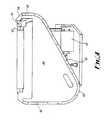
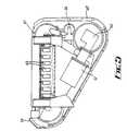
- Figs. 1 and 2show colour detecting apparatus 10 suitable for detecting for example the colour of a gambling chip located approximately at X.
- the apparatus 10comprises a mounting bracket 12 above which is located an electric lamp 14.
- a passage 16is located in front of the top part of the lamp 14 to receive light therefrom.
- a collimator 18is provided at the far end of the passage 16. Beyond the collimator 18 is a downwardly angled mirror 20 which directs light from the lamp 14 downwardly to X.
- the mirror 20is located in a housing 22 which extends beyond X.
- the housing 22mounts a further passage 24 beyond and facing X, with a narrow opening 26 on the end thereof facing X.
- a diffraction grid 28is provided towards the other end of the passage 24 between two convex lenses 30.
- a broader passage 32extends at a downward inclination from the end of the passage 24 with a sixty four position visible detector 34 at the far end thereof.
- Figs. 3-5show a gambling chip sorting apparatus 36.
- the apparatuscomprises a plate 38 inclined downwardly and outwardly at a relatively steep gradient.
- a continuous member in the form of a chain 40extends in a loop over the plate 38 substantially adjacent the edge thereof.
- the chain 40is movable in an anti-clockwise direction from a horizontal upper pass 42, to a long vertical down pass 44, to a gradual upwardly inclined portion 46 to a short vertically upwards extending portion 48.
- the chain 40is drivable by a motor 50 through a gearbox 52.
- An automatic chain tensioning device 54is provided in engagement with the chain 40.
- a plurality of holders(not shown) are provided on the chain 40 with a suitable size circular recess in each for carrying a gambling chip.
- a sprung pusher memberis provided in each holder and arranged so as to eject a chip from the holder when pushed against the spring force.
- An open topped bin 56 with substantially vertical sidesis provided on the front side of the plate 38 with the chain 40 running through the interior thereof.
- a paddle(not shown) may be provided in the bin adjacent the connection between the pass 44 and portion 46 to direct chips into the holders.
- a plate 58is provided spaced from the plate 38 a short distance from the chain 40 such that there is limited clearance between the plate 58 and holders passing thereby.
- the plate 58thereby ensures that any chips carried by the holders are in correct alignment, and only one chip can be carried by each holder.
- the plate 58is located at the far right hand end as shown in Fig. 4 of the upper pass 42.
- the measuring apparatus 10Downstream of the apparatus 10 are ten chip directing stations (not shown in detail).
- Each of the stationscomprises a solenoid 60 operated finger (not shown) engageable with the sprung pusher members on the holders to push a chip off the holder.
- the fingersare generally located behind and slightly above the plate 38 such that chips are pushed in a direction out of the page as shown in Fig. 4.
- the apparatus 36is arranged such that if a chip has not been urged from a holder at a one of the directing stations, either the chip is urged off the holder at the most downstream directing station, or the chip is urged back into the bin 66 before leaving the upper pass 42.
- a nylon cam member 67(Figs. 3 and 5) is provided downstream of the chip directing stations.
- the cam member 67is engageable with each sprung pusher member on the article holders to eject any remaining chips therefrom.
- the cam member 67provides a dual roll in that it also collects dust and dirt in the apparatus 36 by electrostatic attraction.
- the regular enagement of the pusher members, during operation of the apparatus 36, against the member 67causes an electrostatic charge thereon. Dirt/dust can readily be removed from the member 67 when the apparatus 36 is switched off.
- the apparatus 36is mounted on a base 62 with wheels 64 to enable ready movement thereof for example to adjacent a roulette table or elsewhere.
- the apparatus 36is programmed as follows. Each directing station is programmed to a relevant colour chip by detecting and recording the colour of a sample chip placed in the apparatus 10. A plurality of sample chips of each colour may be detected to provide a range of recordings to set tolerances to accept variations of intensity or tone etc. for a particular colour. If required it may be possible to manually adjust the tolerance for any or all colours. Once each directing station has been programmed to be actuable for a respective colour, the apparatus 36 is ready for operation.
- Used chipsare directed into the bin 56.
- the chipsare taken up by the holders carried by the chain 40, perhaps with the assistance of the paddle.
- the chipsare then carried by the chain 40 past the plate 58 to ensure correct alignment.
- the colour of the chipsis then detected by the apparatus 10 in the following manner.
- Light from the lamp 14is focused in the collimator 18 and reflected onto the chip by the mirror 20. Colour is detected as chips move past the apparatus 10 such that colour is detected over a rectangular area on the chips.
- Light reflected from the chip 20passes through the opening 26 and subsequently through the lenses 30 and diffraction grid 28 sandwiched therebetween. Light passing through the grid 28 is diffracted to produce a plurality of spectra to be read by the detector 34.
- the detector 34is arranged to measure light intensity of the red end of a first spectra and the blue end of an adjacent further larger spectra.
- the detector 34is arranged to measure across the whole visible spectrum though in two different spectra. Measuring the larger spectra for the blue end permits a greater number of readings in this area where accurate measurements are more typically difficult to obtain.
- the detector 34measures the light intensity at sixty four positions across the respective spectra, and produces an analog signal which is sent to a control computer (not shown).
- the control computerconverts the analog signal to a digital signal and compares this with the signals previously recorded for the colours of the chips measured during programming. If the colour of a chip being measured corresponds within the tolerances of a one of the previously programmed coloured chips, a signal is sent to the appropriate directing station such that when the corresponding holder is adjacent the respective station, the finger is actuated to move the chip off the holder and into the appropriate place in the storage rack.
- the directing stationsmay be allocated values, and one or more previously read colours may be programmed as having a respective value. This enables different colour/shades of chips to be used for the same value, and is useful with chips which may be differently coloured on each side.
- the apparatusmay be programmed to provide statistical information such as how many chips of each colour and/or value have been sorted over a given period.
- the apparatusmay also be programmed to automatically update previously read colours when the apparatus detects that the colours of corresponding chips gradually changes due for example to the chips becoming dirty and/or fading.
- the computeroperates in real time to perform this function and means are provided to either accurately control the speed of movement of the chain 40 and/or to detect very accurately this speed.
- the colour of the chip detecteddoes not correspond to any of the colours previously detected during programming, the chip is either ejected into a final column of the rack or is returned into the bin 56.
- the apparatusis wholly programmable and can be programmed by detecting the colour of a variety of chips of the same colour to be able to accurately detect chips of the same colour even with variations due perhaps to dirt, age or any manufacturing variations. Measurement across the whole visible spectrum provides for much more accurate detection and means relatively similar colours can be readily distinguished.
- colouris detected over an area on the chips as the chips move past the detecting apparatus 10.
- the colourmay be detected relative to the position on the chip, during movement thereof, preferably with the colour being detected at a large number of discrete points.
- the colour readi.e. intensity and frequency, may be differentiated relative to the position on the chip, i.e. the distance travelled thereby, so as to indicate changes in colour, and the amount thereof.
- the changes in colourwill generally denote boundaries between colours on the chips.
- Apparatus according to the inventioncould be used to sort a wide variety of articles other than gambling chips.
- colour detection apparatus according to the inventioncould be used in a wide range of other applications.
- Apparatus according to the inventioncould be used for example in quality control and perhaps in production to locate extraneous articles.
- the apparatuscould be used to detect colours other than of articles, such as for example of gases or other arrangements.
- the system measuring colour relative to positionis very useful in verifying patterned items such as bank notes.
- the detection across the spectraprovides for a very accurate and sensitive detection. Furthermore, the detection across the blue end of the spectra in a larger spectra relative to the red end provides for greater sensitivity in this part of the spectrum which is generally more difficult to measure. The programmability of the apparatus obviously makes it particularly flexible.
Landscapes
- Physics & Mathematics (AREA)
- General Physics & Mathematics (AREA)
- Pathology (AREA)
- Chemical & Material Sciences (AREA)
- Analytical Chemistry (AREA)
- Biochemistry (AREA)
- General Health & Medical Sciences (AREA)
- Health & Medical Sciences (AREA)
- Immunology (AREA)
- Spectroscopy & Molecular Physics (AREA)
- Life Sciences & Earth Sciences (AREA)
- Spectrometry And Color Measurement (AREA)
- Sorting Of Articles (AREA)
- Measuring Pulse, Heart Rate, Blood Pressure Or Blood Flow (AREA)
- Manufacture, Treatment Of Glass Fibers (AREA)
- Geophysics And Detection Of Objects (AREA)
- Gyroscopes (AREA)
- Inspection Of Paper Currency And Valuable Securities (AREA)
- Heat Sensitive Colour Forming Recording (AREA)
- Food-Manufacturing Devices (AREA)
- Toys (AREA)
Abstract
Description
Claims (41)
- Colour detection apparatus (10) comprising means (34) for detectinglight intensity substantially across the visible spectrum, means forcomparing the read light intensity relative to a previously read lightintensity substantially across the visible spectrum, characterised in thatmeans (28) are provided for splitting the light into one or more spectra.
- Apparatus (10) according to claim 1, characterised in that means areprovided for comparing the read light intensity with previously read lightintensities for one or more known colours.
- Apparatus (10) according to claims 1 or 2, characterised in that means(34) are provided for reading the light intensity at a plurality of closelyspaced intervals across the visible spectrum, and preferably substantiallysixty four spaced intervals.
- Apparatus (10) according to any of the preceding claims,
characterised in that diffraction means (28) are provided for splitting thelight into one or more spectra. - Apparatus (10) according to claim 4, characterised in that adiffraction grid (28) is provided.
- Apparatus (10) according to claim 5, characterised in that means (30)are provided for focusing light onto the diffraction grid (28).
- Apparatus (10) according to any of the preceding claims,
characterised in that the apparatus (10) is arranged to read the lightintensity across respective parts of adjacent spectra, and preferably to readthe red end of one spectra along with the blue end of a larger spectra. - Apparatus (10) according to any of the preceding claims,
characterised in that the apparatus (10) comprises a visible detector (34) capable of measuring light intensity at a plurality of closely spacedintervals, for measuring the respective light intensities across the spectrumor the respective parts of each spectra. - Apparatus (10) for detecting the colour of an article, characterised inthat the apparatus (10) comprises colour detection apparatus according toany of the preceding claims.
- Apparatus (10) according to claim 10, characterised in that theapparatus (10) comprises means (14, 18, 20) for shining light onto thearticle.
- Apparatus (10) according to claims 9 or 10, characterised in that theapparatus (10) is arranged such that the colour is read for at least part of thearticle.
- Apparatus (10) according to claim 11, characterised in that thedetection apparatus (10) is arranged to record the colour detected, i.e. theintensity and frequency, and the positioning of the article, so as to detectchanges in colour and/or pattern across the article.
- Apparatus (10) according to claim 12, characterised in that theapparatus (10) comprises means for differentiating the colour detectedrelative to the position on the article so as to indicate colour changes.
- Apparatus (10) according to any of claims 9 to 13, characterised inthat the apparatus (10) also comprises means for comparing the colourdetected with a plurality of previous colour detections of articles, with thearticles at different orientations.
- Apparatus (10) according to any of claims 9 to 14, characterised inthat the apparatus (10) is arranged to include the detected colour of anarticle in subsequent comparisons, whereby to update the apparatus (10).
- Apparatus (36) for sorting different colour articles, characterised inthat the sorting apparatus (36) comprises apparatus (10) for detecting thecolour of an article according to any of claims 9 to 15, and means (40) forautomatically directing the article to a required location in response to thecolour detected by said colour detecting apparatus (10).
- Apparatus (36) according to claim 16, characterised in that theapparatus (36) comprises means for allocating values to articles, andinputting into the apparatus (36) which colour or colours of article haveeach value; and means for directing articles of each value to a respectiverequired location and preferably also means for recording how many articlesof each value and/or colour have been sorted by the apparatus (36) over agiven time period.
- Apparatus (36) according to claims 16 to 17, characterised in that thesorting apparatus (36) comprises means (40) for automatically supplyingarticles to the colour detecting apparatus (10).
- Apparatus (36) according to claim 18, characterised in that areceptacle (56) is provided for the articles, and from which the supply means(40) takes the articles.
- Apparatus (36) according to claim 19, characterised in that a movablecontinuous member (40) is provided extending through the receptacle (56)for supplying the articles to the colour detecting apparatus (10).
- Apparatus (36) according to claim 20, characterised in that a pluralityof article holders are provided on the continuous member (40).
- Apparatus (36) according to claim 21, characterised in that the sortingapparatus (36) comprises a plurality of engagement members (60)respectively operable in response to the colour detected to move an articleoff a one of the holders such that the article is directed to a respectiverequired location.
- Apparatus (36) according to claim 22, characterised in that theengagement members (60) are located substantially downstream of thecolour detecting apparatus (10) relative to the continuous member (40).
- Apparatus (36) according to claim 23, characterised in that theengagement members (60) are located with a plurality of respective receivingareas on the opposite side of the continuous member (40) thereto.
- Apparatus (36) according to claim 16 or any of claims 17 to 24 whendependent on claim 16, characterised in that the sorting apparatus (36) isarranged such that articles are directed to a respective location if theircolour corresponds to the colour of an article whose colour has beenpreviously detected and recorded during programming of the apparatus (36).
- Apparatus (36) according to any of claims 16 to 25, characterised inthat the apparatus (36) is arranged such that a range of shades and/orintensities of a particular colour article can be detected and recorded duringprogramming, to set tolerances for an article being detected ascorresponding to a particular colour, and preferably means are provided topermit the tolerance of the range of colours considered as corresponding, tobe varied.
- Apparatus (36) according to claim 19 or any of claims 20 to 26 whendependent on claim 19, characterised in that the sorting apparatus (36) isarranged such that all articles which have not previously been directed to arespective required location subsequent to passing the colour detectionapparatus (10), are automatically directed to a final location or returned tothe receptacle (56).
- Apparatus (36) according to any of claims 16 to 27, characterised inthat means (67) are provided in the apparatus for electrostatically collectingdust and dirt and preferably the dust collecting means (67) iselectrostatically charged by virtue of movement of the continuous member(40).
- Apparatus (36) according to claim 20 or any of claims 21 to 28 whendependent on claim 20, characterised in that means are provided forautomatically stopping movement of the continuous member (40) ifresistance to movement thereof above a predetermined limit is detected.
- Apparatus (36) according to claim 29, characterised in that the sortingapparatus (36) is arranged such that movement of the continuous member(40) is reversed for a short period following detection of such increasedresistance with a view to clearing any blockage of articles.
- Apparatus (36) for sorting different colour gambling chips,characterised in that the apparatus (36) is according to any of claims 16 to30.
- A method for checking the colour of an article, the methodcomprising detecting the colour intensity of the article substantially acrossthe visible spectrum by shining light onto the article, and comparing theread colour intensity with a previously read colour intensity substantiallyacross the visible spectrum of an article of a known colour to ascertainwhether the checked article is of the same colour, characterised in that thelight reflected from the articles is split into one or more spectra.
- A method according to claim 32, characterised in that the read colourintensity is compared relative to previously read colour intensities of anarticle at a plurality of different orientations and/or a plurality of articles.
- A method according to claims 32 or 33, characterised in that the lightintensity is read at a plurality of closely spaced intervals across the visiblespectrum, and preferably at substantially sixty four spaced intervals.
- A method according to any of claims 32 to 34, characterised in thatwhere the light is split into more than one spectra, the light intensity is readacross respective parts of adjacent spectra, and preferably the red end of onespectra is read along with the blue end of a larger spectra.
- A method according to any of claims 32 to 35, characterised in thatthe colour intensity is read across at least part of the surface of the articles.
- A method according to claim 36, characterised in that the colourintensity is detected relative to the location of the articles.
- A method according to claim 37, characterised in that the colourintensity read is differentiated relative to the location on the article so as toindicate colour changes.
- A method according to claim 38, characterised in that only colourchanges are stored from previously checked articles, such that only colourchanges are compared.
- A method according to any of claims 32 to 39, characterised in thatthe previously read colour intensities are automatically updated if variationsare noted in subsequent colour intensities for articles of the same colour.
- A method according to any of claims 32 to 40, characterised in thattolerances are set for deciding whether an article is of the same colour as apreviously detected article, and preferably the tolerances are adjustable.
Applications Claiming Priority (5)
| Application Number | Priority Date | Filing Date | Title |
|---|---|---|---|
| GBGB9501359.5AGB9501359D0 (en) | 1995-01-24 | 1995-01-24 | Colour detection apparatus |
| GB9501359 | 1995-01-24 | ||
| GBGB9508633.6AGB9508633D0 (en) | 1995-01-24 | 1995-04-28 | Colour detection apparatus |
| GB9508633 | 1995-04-28 | ||
| PCT/GB1996/000115WO1996023281A1 (en) | 1995-01-24 | 1996-01-23 | Colour detection apparatus |
Publications (2)
| Publication Number | Publication Date |
|---|---|
| EP0806020A1 EP0806020A1 (en) | 1997-11-12 |
| EP0806020B1true EP0806020B1 (en) | 1998-12-30 |
Family
ID=26306363
Family Applications (1)
| Application Number | Title | Priority Date | Filing Date |
|---|---|---|---|
| EP96900629AExpired - LifetimeEP0806020B1 (en) | 1995-01-24 | 1996-01-23 | Colour detection apparatus |
Country Status (11)
| Country | Link |
|---|---|
| US (1) | US6075217A (en) |
| EP (1) | EP0806020B1 (en) |
| AT (1) | ATE175288T1 (en) |
| AU (1) | AU700096B2 (en) |
| CA (1) | CA2229054C (en) |
| DE (1) | DE69601258T2 (en) |
| DK (1) | DK0806020T3 (en) |
| ES (1) | ES2126377T3 (en) |
| GR (1) | GR3029419T3 (en) |
| NZ (1) | NZ298849A (en) |
| WO (1) | WO1996023281A1 (en) |
Cited By (5)
| Publication number | Priority date | Publication date | Assignee | Title |
|---|---|---|---|---|
| US8298052B2 (en) | 2003-02-03 | 2012-10-30 | Shuffle Master Gmbh & Co Kg | Apparatus for sorting articles |
| US8336699B2 (en) | 2009-11-02 | 2012-12-25 | Shuffle Master Gmbh & Co Kg | Chip sorting devices, components therefor and methods of ejecting chips |
| US8393942B2 (en) | 2002-06-05 | 2013-03-12 | Shuffle Master Gmbh & Co Kg | Methods for displacing chips in a chip stack |
| US10096192B1 (en) | 2017-08-30 | 2018-10-09 | Shuffle Master Gmbh & Co Kg | Chip sorting devices and related assemblies and methods |
| US10255741B2 (en) | 2016-04-06 | 2019-04-09 | Shuffle Master Gmbh & Co Kg | Chip sorting devices and related assemblies, components and methods |
Families Citing this family (9)
| Publication number | Priority date | Publication date | Assignee | Title |
|---|---|---|---|---|
| JPH09126890A (en)* | 1995-11-01 | 1997-05-16 | Toshiba Corp | Color inspection device |
| GB2333632A (en) | 1998-01-23 | 1999-07-28 | Technical Casino Services Ltd | Disc sorting apparatus and method |
| SE523567C2 (en)* | 1999-01-08 | 2004-04-27 | Scan Coin Ind Ab | Coin-separating device and method |
| US6567159B1 (en)* | 1999-10-13 | 2003-05-20 | Gaming Analysis, Inc. | System for recognizing a gaming chip and method of use |
| AT6405U1 (en) | 2002-06-05 | 2003-10-27 | Card Casinos Austria Res & Dev | CHIP SORTING DEVICE |
| US20060063586A1 (en)* | 2004-09-23 | 2006-03-23 | Shuffle Master, Inc. | Electronic value marking for wagering chips |
| US20060068878A1 (en)* | 2004-09-29 | 2006-03-30 | Shuffle Master Gmbh & Co Kg | Roulette revenue method and apparatus |
| US20100029374A1 (en)* | 2008-08-04 | 2010-02-04 | Glory Ltd., A Corporation Of Japan | Automatic dealing machine and automatic dealing system |
| CN118162366B (en)* | 2024-04-18 | 2024-08-16 | 江苏暖阳半导体科技有限公司 | LED chip detecting system based on Raman spectrum |
Family Cites Families (9)
| Publication number | Priority date | Publication date | Assignee | Title |
|---|---|---|---|---|
| US4146792A (en)* | 1973-04-30 | 1979-03-27 | G.A.O. Gesellschaft Fur Automation Und Organisation Mbh | Paper secured against forgery and device for checking the authenticity of such papers |
| GB2061490A (en)* | 1979-10-17 | 1981-05-13 | Harwood H L | Sorting Coloured Gambling Chips |
| EP0053183B1 (en)* | 1980-05-30 | 1984-12-12 | GAO Gesellschaft für Automation und Organisation mbH | Paper security with authenticity mark of luminescent material only in an invisible area of the light spectrum and checking method thereof |
| JPS61110016A (en)* | 1984-11-02 | 1986-05-28 | Satake Eng Co Ltd | Photoelectric detector for color selector |
| US5046841A (en)* | 1989-01-19 | 1991-09-10 | Idx, Inc. | Token having a predetermined optical characteristic, and a token validation device for use therewith |
| AT401436B (en)* | 1989-10-16 | 1996-09-25 | Pohanka Christian Ing | DEVICE FOR SORTING CHIPS ON PLAY TABLES |
| JP3098273B2 (en)* | 1991-05-14 | 2000-10-16 | シスメックス株式会社 | Urine cell analyzer |
| EP0517950B1 (en)* | 1991-05-21 | 1996-07-10 | Esm International, Inc. | Sorting machine |
| US5502559A (en)* | 1993-11-01 | 1996-03-26 | Environmental Products Corporation | Apparatus and method for detection of material used in construction of containers and color of same |
- 1996
- 1996-01-23EPEP96900629Apatent/EP0806020B1/ennot_activeExpired - Lifetime
- 1996-01-23ATAT96900629Tpatent/ATE175288T1/ennot_activeIP Right Cessation
- 1996-01-23DKDK96900629Tpatent/DK0806020T3/enactive
- 1996-01-23CACA002229054Apatent/CA2229054C/ennot_activeExpired - Fee Related
- 1996-01-23ESES96900629Tpatent/ES2126377T3/ennot_activeExpired - Lifetime
- 1996-01-23WOPCT/GB1996/000115patent/WO1996023281A1/enactiveIP Right Grant
- 1996-01-23NZNZ298849Apatent/NZ298849A/ennot_activeIP Right Cessation
- 1996-01-23USUS08/875,368patent/US6075217A/ennot_activeExpired - Fee Related
- 1996-01-23AUAU44537/96Apatent/AU700096B2/ennot_activeCeased
- 1996-01-23DEDE69601258Tpatent/DE69601258T2/ennot_activeExpired - Fee Related
- 1999
- 1999-02-17GRGR990400502Tpatent/GR3029419T3/enunknown
Cited By (12)
| Publication number | Priority date | Publication date | Assignee | Title |
|---|---|---|---|---|
| US8393942B2 (en) | 2002-06-05 | 2013-03-12 | Shuffle Master Gmbh & Co Kg | Methods for displacing chips in a chip stack |
| US8298052B2 (en) | 2003-02-03 | 2012-10-30 | Shuffle Master Gmbh & Co Kg | Apparatus for sorting articles |
| US8678164B2 (en) | 2003-02-03 | 2014-03-25 | Shuffle Master Gmbh & Co Kg | Apparatus for receiving and sorting disks |
| US9330516B2 (en) | 2003-02-03 | 2016-05-03 | Shuffle Master Gmbh & Co Kg | Apparatus for receiving and sorting disks |
| US9589407B2 (en) | 2003-02-03 | 2017-03-07 | Shuffle Master Gmbh & Co Kg | Apparatus for receiving and sorting disks |
| US9990792B2 (en) | 2003-02-03 | 2018-06-05 | Shuffle Master Gmbh & Co Kg | Methods and apparatus for receiving and sorting disks |
| US10706656B2 (en) | 2003-02-03 | 2020-07-07 | Shuffle Master Gmbh & Co Kg | Methods and apparatus for receiving and sorting disks |
| US8336699B2 (en) | 2009-11-02 | 2012-12-25 | Shuffle Master Gmbh & Co Kg | Chip sorting devices, components therefor and methods of ejecting chips |
| US8757349B2 (en) | 2009-11-02 | 2014-06-24 | Shuffle Master Gmbh & Co Kg | Methods of ejecting chips |
| US9384616B2 (en) | 2009-11-02 | 2016-07-05 | Shuffle Master Gmbh & Co Kg | Chip handling devices and related methods |
| US10255741B2 (en) | 2016-04-06 | 2019-04-09 | Shuffle Master Gmbh & Co Kg | Chip sorting devices and related assemblies, components and methods |
| US10096192B1 (en) | 2017-08-30 | 2018-10-09 | Shuffle Master Gmbh & Co Kg | Chip sorting devices and related assemblies and methods |
Also Published As
| Publication number | Publication date |
|---|---|
| GR3029419T3 (en) | 1999-05-28 |
| DE69601258D1 (en) | 1999-02-11 |
| DE69601258T2 (en) | 1999-06-17 |
| ATE175288T1 (en) | 1999-01-15 |
| US6075217A (en) | 2000-06-13 |
| EP0806020A1 (en) | 1997-11-12 |
| AU4453796A (en) | 1996-08-14 |
| CA2229054C (en) | 2006-11-07 |
| AU700096B2 (en) | 1998-12-24 |
| CA2229054A1 (en) | 1996-08-01 |
| WO1996023281A1 (en) | 1996-08-01 |
| NZ298849A (en) | 1999-01-28 |
| DK0806020T3 (en) | 1999-08-30 |
| ES2126377T3 (en) | 1999-03-16 |
Similar Documents
| Publication | Publication Date | Title |
|---|---|---|
| EP0806020B1 (en) | Colour detection apparatus | |
| US5933244A (en) | Method of article identification through color determination | |
| RU2635296C2 (en) | Check of precious stones | |
| US5538142A (en) | Sorting apparatus | |
| US6567159B1 (en) | System for recognizing a gaming chip and method of use | |
| EP2281279B1 (en) | Apparatus for producing optical signatures from coinage | |
| US6239867B1 (en) | Apparatus and method for grading, testing, and identifying gemstones | |
| US5531331A (en) | Sorting of differently identified articles | |
| JPH05232030A (en) | Apparatus and method for non-contact type survey and inspection for color label | |
| JPH0147721B2 (en) | ||
| EP1273349B1 (en) | Biochip deposition system and method | |
| EP0798669A3 (en) | Coin discriminating apparatus | |
| WO1998004882A1 (en) | Split optics arrangement for vision inspection/sorter module | |
| JPH07146965A (en) | Disk inspection device | |
| GB2172699A (en) | Apparatus and method for separating mixed products | |
| US8126251B2 (en) | Photo sensor array for banknote evaluation | |
| JP2002257837A (en) | Method for controlling nozzle location for supplying urine sample by detecting location and thickness of reagent pad | |
| US3340978A (en) | Bill acceptance and detection system | |
| KR100775178B1 (en) | Apparatus and method for optical measurement of small particles such as grains from cereals and similar grains | |
| IE893210L (en) | Classifying objects | |
| AU779164B2 (en) | Method and associated apparatus for the standardized grading of gemstones | |
| JPS60137477A (en) | Selector for spherical article | |
| CA1082945A (en) | On-the-paper-machine optical property control system and method |
Legal Events
| Date | Code | Title | Description |
|---|---|---|---|
| PUAI | Public reference made under article 153(3) epc to a published international application that has entered the european phase | Free format text:ORIGINAL CODE: 0009012 | |
| 17P | Request for examination filed | Effective date:19970820 | |
| AK | Designated contracting states | Kind code of ref document:A1 Designated state(s):AT DE DK ES FR GB GR IE IT MC SE | |
| 17Q | First examination report despatched | Effective date:19971113 | |
| GRAG | Despatch of communication of intention to grant | Free format text:ORIGINAL CODE: EPIDOS AGRA | |
| GRAG | Despatch of communication of intention to grant | Free format text:ORIGINAL CODE: EPIDOS AGRA | |
| GRAH | Despatch of communication of intention to grant a patent | Free format text:ORIGINAL CODE: EPIDOS IGRA | |
| GRAH | Despatch of communication of intention to grant a patent | Free format text:ORIGINAL CODE: EPIDOS IGRA | |
| GRAA | (expected) grant | Free format text:ORIGINAL CODE: 0009210 | |
| AK | Designated contracting states | Kind code of ref document:B1 Designated state(s):AT DE DK ES FR GB GR IE IT MC SE | |
| REF | Corresponds to: | Ref document number:175288 Country of ref document:AT Date of ref document:19990115 Kind code of ref document:T | |
| ITF | It: translation for a ep patent filed | ||
| REG | Reference to a national code | Ref country code:IE Ref legal event code:FG4D | |
| REF | Corresponds to: | Ref document number:69601258 Country of ref document:DE Date of ref document:19990211 | |
| REG | Reference to a national code | Ref country code:ES Ref legal event code:FG2A Ref document number:2126377 Country of ref document:ES Kind code of ref document:T3 | |
| ET | Fr: translation filed | ||
| REG | Reference to a national code | Ref country code:DK Ref legal event code:T3 | |
| PLBE | No opposition filed within time limit | Free format text:ORIGINAL CODE: 0009261 | |
| STAA | Information on the status of an ep patent application or granted ep patent | Free format text:STATUS: NO OPPOSITION FILED WITHIN TIME LIMIT | |
| 26N | No opposition filed | ||
| PGFP | Annual fee paid to national office [announced via postgrant information from national office to epo] | Ref country code:GB Payment date:20000121 Year of fee payment:5 | |
| PG25 | Lapsed in a contracting state [announced via postgrant information from national office to epo] | Ref country code:GB Free format text:LAPSE BECAUSE OF NON-PAYMENT OF DUE FEES Effective date:20010123 | |
| GBPC | Gb: european patent ceased through non-payment of renewal fee | Effective date:20010123 | |
| REG | Reference to a national code | Ref country code:GB Ref legal event code:728V | |
| REG | Reference to a national code | Ref country code:GB Ref legal event code:7282 | |
| REG | Reference to a national code | Ref country code:FR Ref legal event code:TP Ref country code:FR Ref legal event code:CA | |
| PGFP | Annual fee paid to national office [announced via postgrant information from national office to epo] | Ref country code:IE Payment date:20090126 Year of fee payment:14 Ref country code:ES Payment date:20090121 Year of fee payment:14 Ref country code:DK Payment date:20090123 Year of fee payment:14 | |
| PGFP | Annual fee paid to national office [announced via postgrant information from national office to epo] | Ref country code:GR Payment date:20090129 Year of fee payment:14 | |
| PGFP | Annual fee paid to national office [announced via postgrant information from national office to epo] | Ref country code:SE Payment date:20090130 Year of fee payment:14 Ref country code:IT Payment date:20090126 Year of fee payment:14 Ref country code:DE Payment date:20090319 Year of fee payment:14 | |
| PGFP | Annual fee paid to national office [announced via postgrant information from national office to epo] | Ref country code:MC Payment date:20090122 Year of fee payment:14 | |
| PGFP | Annual fee paid to national office [announced via postgrant information from national office to epo] | Ref country code:FR Payment date:20090130 Year of fee payment:14 | |
| PGFP | Annual fee paid to national office [announced via postgrant information from national office to epo] | Ref country code:AT Payment date:20100131 Year of fee payment:15 | |
| PG25 | Lapsed in a contracting state [announced via postgrant information from national office to epo] | Ref country code:MC Free format text:LAPSE BECAUSE OF NON-PAYMENT OF DUE FEES Effective date:20100131 | |
| REG | Reference to a national code | Ref country code:DK Ref legal event code:EBP | |
| EUG | Se: european patent has lapsed | ||
| REG | Reference to a national code | Ref country code:FR Ref legal event code:ST Effective date:20100930 | |
| REG | Reference to a national code | Ref country code:IE Ref legal event code:MM4A | |
| PG25 | Lapsed in a contracting state [announced via postgrant information from national office to epo] | Ref country code:FR Free format text:LAPSE BECAUSE OF NON-PAYMENT OF DUE FEES Effective date:20100201 | |
| PG25 | Lapsed in a contracting state [announced via postgrant information from national office to epo] | Ref country code:DE Free format text:LAPSE BECAUSE OF NON-PAYMENT OF DUE FEES Effective date:20100803 | |
| PG25 | Lapsed in a contracting state [announced via postgrant information from national office to epo] | Ref country code:IE Free format text:LAPSE BECAUSE OF NON-PAYMENT OF DUE FEES Effective date:20100125 Ref country code:DK Free format text:LAPSE BECAUSE OF NON-PAYMENT OF DUE FEES Effective date:20100131 | |
| REG | Reference to a national code | Ref country code:ES Ref legal event code:FD2A Effective date:20110228 | |
| PG25 | Lapsed in a contracting state [announced via postgrant information from national office to epo] | Ref country code:IT Free format text:LAPSE BECAUSE OF NON-PAYMENT OF DUE FEES Effective date:20100123 | |
| PG25 | Lapsed in a contracting state [announced via postgrant information from national office to epo] | Ref country code:ES Free format text:LAPSE BECAUSE OF NON-PAYMENT OF DUE FEES Effective date:20110224 | |
| PG25 | Lapsed in a contracting state [announced via postgrant information from national office to epo] | Ref country code:ES Free format text:LAPSE BECAUSE OF NON-PAYMENT OF DUE FEES Effective date:20100124 | |
| PG25 | Lapsed in a contracting state [announced via postgrant information from national office to epo] | Ref country code:AT Free format text:LAPSE BECAUSE OF NON-PAYMENT OF DUE FEES Effective date:20110123 | |
| PG25 | Lapsed in a contracting state [announced via postgrant information from national office to epo] | Ref country code:SE Free format text:LAPSE BECAUSE OF NON-PAYMENT OF DUE FEES Effective date:20100124 |