EP0805652B1 - Device for collecting endometrial fragments - Google Patents
Device for collecting endometrial fragmentsDownload PDFInfo
- Publication number
- EP0805652B1 EP0805652B1EP96939989AEP96939989AEP0805652B1EP 0805652 B1EP0805652 B1EP 0805652B1EP 96939989 AEP96939989 AEP 96939989AEP 96939989 AEP96939989 AEP 96939989AEP 0805652 B1EP0805652 B1EP 0805652B1
- Authority
- EP
- European Patent Office
- Prior art keywords
- tube
- distal end
- wall
- patient
- uterine
- Prior art date
- Legal status (The legal status is an assumption and is not a legal conclusion. Google has not performed a legal analysis and makes no representation as to the accuracy of the status listed.)
- Expired - Lifetime
Links
- 239000012634fragmentSubstances0.000titleclaimsabstractdescription10
- 230000002357endometrial effectEffects0.000title1
- 210000001835visceraAnatomy0.000claimsabstractdescription3
- 239000003082abrasive agentSubstances0.000claimsdescription3
- 210000004696endometriumAnatomy0.000claimsdescription3
- 239000000126substanceSubstances0.000claimsdescription3
- 230000002708enhancing effectEffects0.000abstract1
- 238000005070samplingMethods0.000description20
- 238000007790scrapingMethods0.000description7
- 210000003679cervix uteriAnatomy0.000description6
- 230000002380cytological effectEffects0.000description6
- 210000004027cellAnatomy0.000description5
- 210000004400mucous membraneAnatomy0.000description5
- 210000004291uterusAnatomy0.000description5
- 238000004458analytical methodMethods0.000description4
- 239000007788liquidSubstances0.000description3
- 238000006073displacement reactionMethods0.000description2
- 210000002919epithelial cellAnatomy0.000description2
- 239000000463materialSubstances0.000description2
- 210000004877mucosaAnatomy0.000description2
- 239000004033plasticSubstances0.000description2
- 238000004321preservationMethods0.000description2
- DHKHKXVYLBGOIT-UHFFFAOYSA-N1,1-DiethoxyethaneChemical compoundCCOC(C)OCCDHKHKXVYLBGOIT-UHFFFAOYSA-N0.000description1
- 206010003694AtrophyDiseases0.000description1
- 206010008342Cervix carcinomaDiseases0.000description1
- 229920000742CottonPolymers0.000description1
- 206010014733Endometrial cancerDiseases0.000description1
- 206010014759Endometrial neoplasmDiseases0.000description1
- 239000004743PolypropyleneSubstances0.000description1
- 208000006105Uterine Cervical NeoplasmsDiseases0.000description1
- 239000011354acetal resinSubstances0.000description1
- 230000037444atrophyEffects0.000description1
- 201000010881cervical cancerDiseases0.000description1
- 230000000295complement effectEffects0.000description1
- 238000003745diagnosisMethods0.000description1
- 238000010586diagramMethods0.000description1
- 238000013399early diagnosisMethods0.000description1
- 230000000694effectsEffects0.000description1
- 210000000981epitheliumAnatomy0.000description1
- 238000000605extractionMethods0.000description1
- 239000012530fluidSubstances0.000description1
- 238000002695general anesthesiaMethods0.000description1
- 208000015181infectious diseaseDiseases0.000description1
- 238000012544monitoring processMethods0.000description1
- 210000003101oviductAnatomy0.000description1
- 238000009595pap smearMethods0.000description1
- 238000005498polishingMethods0.000description1
- 229920006324polyoxymethylenePolymers0.000description1
- -1polypropylenePolymers0.000description1
- 229920001155polypropylenePolymers0.000description1
- 239000011148porous materialSubstances0.000description1
- 230000035935pregnancyEffects0.000description1
- 230000001737promoting effectEffects0.000description1
- 238000012216screeningMethods0.000description1
- 238000004659sterilization and disinfectionMethods0.000description1
- 238000004381surface treatmentMethods0.000description1
- 210000001519tissueAnatomy0.000description1
- 239000012780transparent materialSubstances0.000description1
- 230000003313weakening effectEffects0.000description1
Images

Classifications
- A—HUMAN NECESSITIES
- A61—MEDICAL OR VETERINARY SCIENCE; HYGIENE
- A61B—DIAGNOSIS; SURGERY; IDENTIFICATION
- A61B10/00—Instruments for taking body samples for diagnostic purposes; Other methods or instruments for diagnosis, e.g. for vaccination diagnosis, sex determination or ovulation-period determination; Throat striking implements
- A61B10/02—Instruments for taking cell samples or for biopsy
- A61B10/0291—Instruments for taking cell samples or for biopsy for uterus
- A—HUMAN NECESSITIES
- A61—MEDICAL OR VETERINARY SCIENCE; HYGIENE
- A61B—DIAGNOSIS; SURGERY; IDENTIFICATION
- A61B17/00—Surgical instruments, devices or methods
- A61B17/32—Surgical cutting instruments
- A61B2017/320004—Surgical cutting instruments abrasive
Definitions
- the present inventionrelates to a device able to allow remove fragments from the inner lining of the uterus, such as fragments of mucous membranes.
- This type of devicegenerally comprises a cylindrical tube, of a outer diameter of about 3 millimeters and inner diameter of 1.5 to 2.6 millimeters, for a length of about 25 centimeters.
- the tubeis open at one end (proximal end) and has at its opposite end (distal end) a hole, with a diameter about 2 millimeters, said suction hole and provided on the wall cylindrical of the tube, i.e. in a plane parallel to the axis longitudinal of the tube.
- a pistonattached to the distal end of a rod, while the other end (proximal) of the rod is integral with a gripping member.
- thisis introduced through the patient's cervix, up to uterine fundus. Graduations provided on the tube allow locate the arrival of the distal end of the tube (provided with the hole), at beginning of the uterine cavity.
- the operatorwhile holding the tube in pulling on the rod, by the gripping member, in the direction of the distance from the patient, achieves depression at inside the tube, and therefore a suction phenomenon at the level of the hole at the distal end of the tube.
- the removal of fragments of the uterine wall and uterine liningis made by moving the tube, preferably by longitudinal reciprocating movement, and rotation around the longitudinal axis, while maintaining the end distal of the tube against the wall.
- Fragments of mucous membranesare therefore torn from the wall and are sucked into the tube at through the suction hole.
- the latterin side view, in a plane transverse to the axis of the hole, has a concavity turned towards the outside of the tube.
- the edges of the holeform a bowl whose concavity is turned towards the outside of the tube.
- the operatorremoves the device and then pours the contents of the tube resulting from samples, in a container containing a fixing liquid histologically.
- the end of the tubehas a rough surface on the periphery of said tube and preferably over a length, in the longitudinal direction of the tube, between 2 and 50 millimeters, and preferably between 5 and 20 millimeters.
- the rough surface of the end of the tubeis treated by rubbing with an abrasive material.
- At least part of the rough surface of the tube endis under attack chemical, so as to create micro-porosities on the surface, or equivalent, to achieve the desired degree of roughness.
- the surface treated in order to increase the roughness of the outer surface of the tubeis arranged below the hole suction, relative to the distal end of said tube.
- the sampling device carrying the general reference 1includes a cylindrical tube 2, based circular, and having an opening 3 at one of its ends, at know the proximal end, in other words the furthest of the patient.
- the opposite end, or distal end, and referenced 4,is closed, with the exception of a suction hole 5, of cross section preferably circular.
- the outside diameter of the tube 2is between 2 and 4 millimeters and, according to a particular example, equal to 3.14 millimeters, and the diameter inside of the tube is 2.6 millimeters for example.
- the tubehas a length of 20 to 30 centimeters, and by example of 23.5 centimeters.
- the diameter of the holeis about 2 millimeters, and preferably 2.1 mm.
- Tube 2includes marks or markers, one of which bears the reference 6, arranged in planes transverse to the axis longitudinal of the tube.
- a piston 7in the form of a ring or washer, of external diameter substantially equivalent to the diameter inside the tube.
- the piston 7is integral with the distal end of a rod 8 whose proximal end (on the patient's side) is integral a handle 9 ( Figure 1).
- the marks 6allow, in known manner, to ensure the arrival from the distal end 4, at the beginning of the uterus.
- the deviceis moved, by direction back and forth movement longitudinal, combined with a rotational movement, in the cavity uterine, to allow the displacement of the aspiration hole 5 by relation to the uterine wall from which the mucous membranes are taken.
- Figure 3shows an embodiment of the invention, in addition large scale, and more precisely the distal end portion 4 of the tube 2, where the suction hole 5 is arranged.
- a zone 10, shown in gray / hatched on the tube 2corresponds to a particular surface condition of the tube 2, on its outer wall.
- the state surface of this areais such that it has properties of roughness greater than the rest of the surface of the tube 2.
- the tube 2is preferably in the zone 10, surface treated on a length of about 10 millimeters and, more preferably, on the entire circumference of the tube.
- the surface treatmentcan be carried out by scraping, polishing, or any other similar operation, using an abrasive material, and capable of create micro-roughness or micro-pores.
- the rough area 10is preferably located near the suction hole 5.
- the rough surface finish of zone 10can also be carried out by chemical attack on the material constituting the tube 2.
- the tube 2is advantageously made of plastic transparent, such as polypropylene.
- the pistonis EVA, while that the rod 8 is for example made of flexible acetal resin.
- the device of the inventionis preferably for single use and can present any variation in terms of shape and size, without depart from the scope of the invention.
- the present inventionrelates to an endo-uterine sampling device for single use.
- Routine Pap smear screening for cervical cancerhas allowed to reduce, to a large extent, the mortality rate which was attributable by promoting its early diagnosis.
- This deviceis schematically constituted by a flexible and smooth sampling tube intended to be introduced into the uterine cavity and by a movable piston the inside of this tube and connected by a rod with an actuating button protruding through the open proximal end of the tube.
- the end closed and rounded distal of this tubehas a hole, and as a rule a side hole about 2mm in diameter; this orifice allows the suction, to the part internal tube, uterine lining under the action of depression created by a displacement of the piston towards the end proximal, following the pulling of the actuation button performed by the practitioner.
- the mucosa thus torn offis introduced into the internal part of the tube of sample, then transferred after extraction of the device, to a bottle containing a preservation liquid, using the plunger after sectioning of the tube at its distal end, in view from his histological study.
- this devicehas the disadvantage of do not allow scraping of the endo-uterine lining when the uterine lining does not come off, as it does when atrophy exists or in postmenopausal patients.
- the object of the present inventionis to provide a device for single-use endo-uterine sample of the above type which is likely to remedy these drawbacks while allowing perform, in addition to the usual histological sample, a cytological sampling to complement it when it is not possible to detach the uterine lining.
- the inventionrelates to an endo-uterine sampling device single use characterized in that the outer surface of the tube is rough at its distal end so as to allow a double sample by scraping the cells epithelial at this level in addition to histological sampling.
- the roughnesspreferably extends over the whole of the periphery of the distal end of the sampling tube, this on a length of about 1 to 1.5 cm. This can advantageously be obtained by a running-in operation at this level of the material (as a rule general of the plastic) constituting the sampling tube.
- the distal end of the type of sampleallows to create a friction likely to detach the epithelial cells; the cells thus detached can then be sucked under the effect of a vacuum induced by the piston then spread on a slide so as to obtain an endo-uterine sample cytological comparable to the smear of the cervix; we can also thus analyze the cells that remained attached to the area rough.
- the essential advantage of the endo-uterine sample according to the inventionis therefore to allow perform both a histological sample and a sample cytology; indeed, after cutting the sampling tube at level of its distal end using scissors, the contents thereof can either be spread on a slide, if the sample is intended cytological, either be placed in a storage fluid, if the sampling is for histological purpose, either by spreading out the part lapped on slides with cytological aim after having regrown using of the piston the contents of the tube for histological study.
- the deviceis essentially constituted by a tube sampling 100 made of a flexible and smooth transparent material and having a length of around 23 cm and a diameter of around 3 mm.
- This tube 100has a rounded and closed distal end 20 by which it is intended to be introduced into the uterine cavity and a open proximal end 30.
- a piston 40measuring approximately 1 cm in length, can slide at the internal part of the sampling tube 100.
- This piston 40is connected by a rod 50 to an actuating button 60 projecting from the open proximal end 3 of the tube so as to allow the practitioner to move the piston 40.
- a flattened part 70 provided at the proximal end 30 of the tube 100makes it possible to prevent any untimely exit from the piston 40.
- Marking graduations 80located on the periphery of the tube sampling 100 in particular 4,5,6,7,8,9 and 10 cm from its end distal 2, measure the depth of the uterus.
- the distal end 20 of the tube 100is moreover provided with an orifice side suction 90 measuring approximately 2 mm in diameter as well as of a lapped part 1001 extending over the length of 1 to 1.5 cm over the entire periphery of the sampling tube 100.
- This lapped part 1001is shown hatched in the figures.
- the collection tube 100is gently pushed to the bottom of the uterus. It is to highlight that the passage of the cervix is usually painless for the patient. Prior to this introduction, the practitioner can, if necessary, bend the tube to pre-bend it.
- the piston 40must be located at the level of the distal end 20 of the tube 100.
- the practitionerWhen it has been placed at the bottom of the uterine cavity, the practitioner creates a depression by pulling, according to arrow a, on the button actuation 6, and therefore, by moving the piston 40 towards the end 30 of the tube 100.
- Tissue fragments detached from the endometriumcan thus be sucked according to arrow b to the internal part of the tube 100.
- the practitionermoves the tube 100 by circular helical movements from the bottom to the edge of the uterus so that the lapped part 1001 comes exert an action of friction and circular scraping likely detaching epithelial cells; these can then be drawn into the internal part of tube 1 under the action of vacuum induced by the tube 40; it is therefore added to the histological sample by aspiration and detachment of the uterine lining, a function of scraping of the epithelium.
- the contents of the tubeare then pushed back using the piston 40 from the actuation button 60, and is either, as shown in FIG. 6, introduced according to the arrow A in the bottle 120 containing a preservation liquid 130 when the sample is for histological purpose, or spread on a slide if the sample is for cytological purposes.
- the inventionalso makes it possible to carry out these two types at the same time. analysis by pushing the inner part of the tube 100 back into a bottle 120, as shown in FIG. 5, and spreading out the lapped part external 1001 on a blade 140 as shown in FIG. 5, in a manner largely comparable to that allowing smear from the cervix.
Landscapes
- Health & Medical Sciences (AREA)
- Life Sciences & Earth Sciences (AREA)
- Surgery (AREA)
- Animal Behavior & Ethology (AREA)
- Reproductive Health (AREA)
- Engineering & Computer Science (AREA)
- Biomedical Technology (AREA)
- Heart & Thoracic Surgery (AREA)
- Medical Informatics (AREA)
- Molecular Biology (AREA)
- Gynecology & Obstetrics (AREA)
- Pathology (AREA)
- General Health & Medical Sciences (AREA)
- Public Health (AREA)
- Veterinary Medicine (AREA)
- Surgical Instruments (AREA)
- Saccharide Compounds (AREA)
- Measuring And Recording Apparatus For Diagnosis (AREA)
- External Artificial Organs (AREA)
- Braking Arrangements (AREA)
- Carbon And Carbon Compounds (AREA)
- Friction Gearing (AREA)
Abstract
Description
Translated fromFrenchLa présente invention concerne un dispositif apte à permettre deprélever des fragments de la paroi interne de l'utérus, tels que desfragments de muqueuses.The present invention relates to a device able to allowremove fragments from the inner lining of the uterus, such asfragments of mucous membranes.
Ce type de dispositif comprend généralement un tube cylindrique, d'undiamètre extérieur d'environ 3 millimètres et de diamètre interne de 1,5à 2,6 millimètres, pour une longueur d'environ 25 centimètres. Le tubeest ouvert à une première extrémité (extrémité proximale) et comporteà son extrémité opposée (extrémité distale) un trou, d'un diamètred'environ 2 millimètres, dit trou d'aspiration et prévu sur la paroicylindrique du tube, c'est-à-dire dans un plan parallèle à l'axelongitudinal du tube. A l'intérieur de ce dernier, est apte à coulisser unpiston fixé à l'extrémité distale d'une tige, tandis que l'autre extrémité(proximale) de la tige est solidaire d'un organe de préhension.This type of device generally comprises a cylindrical tube, of aouter diameter of about 3 millimeters and inner diameter of 1.5to 2.6 millimeters, for a length of about 25 centimeters. The tubeis open at one end (proximal end) and hasat its opposite end (distal end) a hole, with a diameterabout 2 millimeters, said suction hole and provided on the wallcylindrical of the tube, i.e. in a plane parallel to the axislongitudinal of the tube. Inside the latter, is able to slide apiston attached to the distal end of a rod, while the other end(proximal) of the rod is integral with a gripping member.
Ce type de dispositif est plus connu sous la dénomination commercialePIPELLE DE CORNIER (marque déposées), (voir par exemple ledocument FR-A-2 602 414).This type of device is better known under the trade namePIPELLE DE CORNIER (registered trademark), (see for example thedocument FR-A-2 602 414).
L'utilisation, en général à usage unique, de ce dispositif connu est lasuivante : celui-ci est introduit à travers le col de la patiente, jusqu'aufond utérin. Des graduations prévues sur le tube permettent delocaliser l'arrivée de l'extrémité distale du tube (pourvu du trou), audébut de la cavité utérine. L'opérateur, tout en maintenant le tube entirant sur la tige, par l'organe de préhension, dans le sens del'éloignement par rapport à la patiente, réalise une dépression àl'intérieur du tube, et donc un phénomène d'aspiration au niveau du trou disposé à l'extrémité distale du tube. Le prélèvement de fragmentsde la paroi utérine et de la muqueuse utérine est réalisé en déplaçant letube, de préférence par mouvement de va-et-vient longitudinal, et derotation autour de l'axe longitudinal, tout en maintenant l'extrémitédistale du tube contre la paroi. Des fragments de muqueuses setrouvent donc arrachés de la paroi et sont aspirés dans le tube autravers du trou d'aspiration. Ce dernier, en vue de côté, dans un plantransversal à l'axe du trou, présente une concavité tournée versl'extérieur du tube. En d'autres termes, toujours en vue de côté, lesbords du trou forment une cuvette dont la concavité est tournée versl'extérieur du tube.The use, generally for single use, of this known device is thefollowing: this is introduced through the patient's cervix, up touterine fundus. Graduations provided on the tube allowlocate the arrival of the distal end of the tube (provided with the hole), atbeginning of the uterine cavity. The operator, while holding the tube inpulling on the rod, by the gripping member, in the direction ofthe distance from the patient, achieves depression atinside the tube, and therefore a suction phenomenon at the level of thehole at the distal end of the tube. The removal of fragmentsof the uterine wall and uterine lining is made by moving thetube, preferably by longitudinal reciprocating movement, androtation around the longitudinal axis, while maintaining the enddistal of the tube against the wall. Fragments of mucous membranesare therefore torn from the wall and are sucked into the tube atthrough the suction hole. The latter, in side view, in a planetransverse to the axis of the hole, has a concavity turned towardsthe outside of the tube. In other words, still in side view, theedges of the hole form a bowl whose concavity is turned towardsthe outside of the tube.
Une fois l'opération de prélèvement effectuée, l'opérateur retire ledispositif et ensuite déverse le contenu du tube résultant desprélèvements, dans un récipient contenant un liquide de fixationhistologique.Once the removal operation has been carried out, the operator removes thedevice and then pours the contents of the tube resulting fromsamples, in a container containing a fixing liquidhistologically.
On comprend que ce type de dispositif doit permettre de prélever desfragments de parois (muqueuses) utérines, de manière fiable, et bienentendu sans douleur. Également, le prélèvement doit être représentatifet donc régulier, en terme de profondeur, dans un plan transversal à laparoi. Le prélèvement doit être également aisé et rapide pour raccourcirau maximum l'opération de prélèvement, compte tenu desdésagréments qu'elle comporte pour la patiente.It is understood that this type of device must make it possible to take samplesfragments of uterine walls (mucous membranes), reliably, and wellheard painlessly. Also, the sample must be representativeand therefore regular, in terms of depth, in a plane transverse to thewall. Sampling must also be easy and quick to shortenmaximum the direct debit operation, taking into accountinconvenience it involves for the patient.
Les dispositifs connus et mentionnés ci-dessus donnent relativementsatisfaction.The known devices mentioned above give relativelysatisfaction.
Cependant, ils sont susceptibles d'amélioration, et c'est un des objetsde la présente invention de proposer un dispositif de prélèvementperfectionné présentant des conditions d'utilisation améliorées,notamment en termes de fiabilité et de conditions de prélèvementoptimales, tout en respectant les conditions requises et rappelées ci-dessus.However, they are subject to improvement, and this is one of the objectsof the present invention to provide a sampling deviceimproved with improved conditions of use,especially in terms of reliability and sampling conditionsoptimal, while respecting the conditions required and recalled above.
A cet effet, selon l'invention, le dispositif de prélèvement de fragmentsde parois d'organes internes, tels que la paroi utérine, du typecomportant :
- un tube dont l'extrémité proximale (la plus éloignée de la patiente)est ouverte et dont l'extrémité opposée (distale) est obturée, àl'exception d'un trou dit d'aspiration ;
- un piston étanche apte à se déplacer dans ledit tube et relié àl'extrémité distale d'une tige dont l'extrémité proximale (opposée àla patiente) est pourvue d'un organe de préhension ;
- a tube whose proximal end (furthest from the patient) is open and whose opposite (distal) end is closed, with the exception of a so-called suction hole;
- a sealed piston able to move in said tube and connected to the distal end of a rod whose proximal end (opposite to the patient) is provided with a gripping member;
Avantageusement, l'extrémité du tube présente une surface rugueusesur la périphérie dudit tube et de préférence sur une longueur, dans lesens longitudinal du tube, comprise entre 2 et 50 millimètres, et depréférence entre 5 et 20 millimètres.Advantageously, the end of the tube has a rough surfaceon the periphery of said tube and preferably over a length, in thelongitudinal direction of the tube, between 2 and 50 millimeters, andpreferably between 5 and 20 millimeters.
Selon une première forme de réalisation, la surface rugueuse del'extrémité du tube est traitée par frottement avec un matériau abrasif.According to a first embodiment, the rough surface ofthe end of the tube is treated by rubbing with an abrasive material.
Selon une autre forme de mise en oeuvre, une partie au moins de lasurface rugueuse de l'extrémité du tube est soumise à une attaquechimique, de manière à créer des micro-porosités en surface, ouéquivalent, pour atteindre le degré de rugosité voulu.According to another form of implementation, at least part of therough surface of the tube end is under attackchemical, so as to create micro-porosities on the surface, orequivalent, to achieve the desired degree of roughness.
De manière avantageuse, la surface traitée en vue d'augmenter larugosité de la surface extérieure du tube, est disposée en deçà du troud'aspiration, par rapport à l'extrémité distale dudit tube.Advantageously, the surface treated in order to increase theroughness of the outer surface of the tube, is arranged below the holesuction, relative to the distal end of said tube.
L'invention sera bien comprise à la lumière de la description qui suit serapportant à un exemple illustratif et non limitatif, en référence audessin annexé dans lequel :
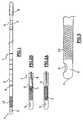
- la figure 1 est une représentation en plan du dispositif deprélèvement ;
Les figures 2A et 2B montrent l'extrémité distale du tube pour deuxpositions différentes du piston ; et - la figure 3 est une représentation schématique, à échelle agrandie,de l'extrémité distale du tube.
- Figure 1 is a plan view of the sampling device;
Figures 2A and 2B show the distal end of the tube for two different positions of the piston; and - Figure 3 is a schematic representation, on an enlarged scale, of the distal end of the tube.
Comme montré sur la figure 1, le dispositif de prélèvement portant laréférence générale 1, comprend un tube cylindrique 2, à basecirculaire, et comportant une ouverture 3 à l'une de ses extrémités, àsavoir l'extrémité proximale, en d'autres termes celle la plus éloignéede la patiente. L'extrémité opposée, ou extrémité distale, et référencée4, est obturée, à l'exception d'un trou d'aspiration 5, de section depréférence circulaire.As shown in Figure 1, the sampling device carrying thegeneral reference 1, includes a
Le diamètre extérieur du tube 2 est compris entre 2 et 4 millimètres et,selon un exemple particulier, égal à 3,14 millimètres, et le diamètreintérieur du tube est de 2,6 millimètres par exemple. Toujours à titreillustratif, le tube présente une longueur de 20 à 30 centimètres, et parexemple de 23,5 centimètres. Le diamètre du trou est d'environ 2millimètres, et de préférence de 2,1 mm.The outside diameter of the
Le tube 2 comprend des marques ou repères, dont l'un d'entre euxporte la référence 6, disposés dans des plans transversaux à l'axelongitudinal du tube.
En référence aux figures 2A et 2B, à l'intérieur du tube 2, estsusceptible de coulisser un piston 7, sous la forme d'une bague ourondelle, de diamètre extérieur sensiblement équivalent au diamètreintérieur du tube. Le piston 7 est solidaire de l'extrémité distale d'unetige 8 dont l'extrémité proximale (du côté de la patiente) est solidaired'une poignée 9 (figure 1).With reference to FIGS. 2A and 2B, inside the
En partant de la position de départ représentée sur la figure 2A,l'opérateur, tout en maintenant le tube 2, tire sur la poignée 9, dans lesens de la flèche f (figure 2B); la tige 8 et le piston 7 se trouvententraínés dans la même direction (vers la patiente). Ce faisant, il secrée une dépression au niveau du trou d'aspiration 5.Starting from the starting position shown in FIG. 2A,the operator, while holding the
L'aspiration ainsi créée au niveau du trou 5, entraíne dans le tube 2 lesmuqueuses détachées de la paroi utérine où le dispositif est introduit.Les repères 6 permettent, de manière connue, de s'assurer de l'arrivéede l'extrémité distale 4, au début de l'utérus. De manière traditionnelle,le dispositif est déplacé, par mouvement de va-et-vient de directionlongitudinale, combiné avec un mouvement de rotation, dans la cavitéutérine, afin de permettre le déplacement du trou d'aspiration 5 parrapport à la paroi utérine d'où sont prélevées les muqueuses.The suction thus created at the hole 5, drives in the
La figure 3 montre une forme de réalisation de l'invention, à plusgrande échelle, et plus précisément la partie d'extrémité distale 4 dutube 2, où est disposé le trou d'aspiration 5.Figure 3 shows an embodiment of the invention, in additionlarge scale, and more precisely the distal end portion 4 of the
Une zone 10, représentée en grisé/hachuré sur le tube 2, correspond àun état de surface particulier du tube 2, sur sa paroi extérieure. L'étatde surface de cette zone est tel qu'il présente des propriétés derugosité supérieures au reste de la surface du tube 2.A
Le tube 2 est, de préférence, dans la zone 10, traité en surface sur unelongueur d'environ 10 millimètres et, de préférence encore, sur latotalité du pourtour du tube.The
Le traitement de surface peut être effectué par grattage, polissage, outout autre opération similaire, à l'aide d'un matériau abrasif, et apte àcréer des micro-rugosités ou micro-pores. La zone rugueuse 10 est depréférence disposée à proximité du trou d'aspiration 5.The surface treatment can be carried out by scraping, polishing, orany other similar operation, using an abrasive material, and capable ofcreate micro-roughness or micro-pores. The
L'état de surface rugueux de la zone 10 peut être également effectuépar attaque chimique du matériau constituant le tube 2.The rough surface finish of
Le tube 2 est avantageusement réalisé en matière plastiquetransparente, telle que du polypropylène. Le piston est en EVA, tandisque la tige 8 est par exemple en résine d'acétal souple.The
Le dispositif de l'invention est, de préférence, à usage unique et peutprésenter toute variation en terme de forme et de dimension, sanssortir du cadre de l'invention.The device of the invention is preferably for single use and canpresent any variation in terms of shape and size, withoutdepart from the scope of the invention.
La présente invention a pour objet un dispositif de prélèvement endo-utérinà usage unique.The present invention relates to an endo-uterine sampling devicefor single use.
Le dépistage systématique, par frottis, du cancer du col de l'utérus apermis de réduire, dans une large mesure, le taux de mortalité qui luiétait imputable en favorisant son diagnostic précoce.Routine Pap smear screening for cervical cancer hasallowed to reduce, to a large extent, the mortality rate whichwas attributable by promoting its early diagnosis.
Dans ce but, les gynécologues ont depuis déjà de nombreuses annéespris l'habitude de surveiller régulièrement leurs patientes en prélevant,par raclage, des cellules au niveau de leur col utérin au moyen despatules, bâtonnets, coton tiges, ... avant de les étaler sur des lamesde façon à permettre leur analyse.For this purpose, gynecologists have already for many yearsgot into the habit of regularly monitoring their patients when collecting,by scraping, cells at the level of their cervix by means ofspatulas, sticks, cotton swabs, ... before spreading them on bladesso as to allow their analysis.
De telles analyses ne s'avèrent cependant pas toujours suffisantes, etne permettent, en particulier pas de détecter ou de confirmer undiagnostic de cancer de l'endomètre. Il est en effet indispensable dansce but d'effectuer des prélèvements au niveau de la muqueuseépithéliale, donc à la partie interne de la cavité utérine, notammentpour permettre une étude à visée histologique.However, such analyzes are not always sufficient, anddo not, in particular, detect or confirm adiagnosis of endometrial cancer. It is indeed essential inthis purpose of taking samples from the mucosaepithelial, therefore to the internal part of the uterine cavity, in particularto allow a histological study.
Pendant longtemps, de tels prélèvements ne pouvaient être effectuésque par curetage, sous anesthésie générale.For a long time, such withdrawals could not be madeonly by curettage, under general anesthesia.
Depuis quelques années, on a créé un dispositif à usage uniquespécialement adapté à de tels prélèvements qui a immédiatementrencontré un grand succès auprès des praticiens.In recent years, we have created a disposable devicespecially adapted for such direct debits which immediatelymet with great success with practitioners.
Ce dispositif, connu sous le nom de «Pipelle de Cornier», estschématiquement constitué par un tube de prélèvement souple et lissedestiné à être introduit dans la cavité utérine et par un piston mobile àl'intérieur de ce tube et relié par une tige à bouton d'actionnementfaisant saillie par l'extrémité proximale ouverte du tube. L'extrémitédistale fermée et arrondie de ce tube, dont le diamètre est de l'ordre de3mm, est percée d'un orifice, et en règle générale d'un orifice latérald'environ 2mm de diamètre; cet orifice permet l'aspiration, à la partieinterne du tube, de la muqueuse utérine sous l'action de la dépressioncréée par un déplacement du piston en direction de l'extrémitéproximale, suite au tirage du bouton d'actionnement effectué par lepraticien.This device, known as the "Cornier Pipelle", isschematically constituted by a flexible and smooth sampling tubeintended to be introduced into the uterine cavity and by a movable pistonthe inside of this tube and connected by a rod with an actuating buttonprotruding through the open proximal end of the tube. The endclosed and rounded distal of this tube, the diameter of which is of the order of3mm, has a hole, and as a rule a side holeabout 2mm in diameter; this orifice allows the suction, to the partinternal tube, uterine lining under the action of depressioncreated by a displacement of the piston towards the endproximal, following the pulling of the actuation button performed by thepractitioner.
La muqueuse ainsi arrachée est introduite à la partie interne du tube deprélèvement, puis transférée après extraction du dispositif, dans un flacon contenant un liquide de conservation, à l'aide du piston aprèssectionnement du tube au niveau de son extrémité distale, ce en vuede son étude histologique.The mucosa thus torn off is introduced into the internal part of the tube ofsample, then transferred after extraction of the device, to abottle containing a preservation liquid, using the plunger aftersectioning of the tube at its distal end, in viewfrom his histological study.
Malgré ses avantages certains, ce dispositif présente l'inconvénient dene pas permettre de gratter le revêtement endo-utérin lorsque lamuqueuse utérine ne se détache pas, comme c'est le cas lorsqu'uneatrophie existe ou chez les patientes ménopausées.Despite its certain advantages, this device has the disadvantage ofdo not allow scraping of the endo-uterine lining when theuterine lining does not come off, as it does whenatrophy exists or in postmenopausal patients.
Pour remédier à cet inconvénient, on a déjà proposé d'adjoindre àl'extrémité du dispositif de prélèvement endo-utérin divers types debrosses (voir par exemple les documents US-A-3 088 454 et GB-A-1 573 819) permettant le grattage et le détachement des cellulesépithéliales pour permettre leur étude cytologique; l'adjonction de tellesbrosses présente toutefois, l'inconvénient de fragiliser le dispositif, eten outre, d'augmenter notablement le diamètre du tube deprélèvement, et par voie de conséquence de nuire au confort de lapatiente.To remedy this drawback, it has already been proposed to add tothe end of the endo-uterine sampling device various types ofbrushes (see for example documents US-A-3 088 454 and GB-A-1 573 819) allowing scraping and detachment of cellsepithelial to allow their cytological study; the addition of suchbrushes, however, have the disadvantage of weakening the device, andin addition, to significantly increase the diameter of theremoval, and as a consequence to harm the comfort of thepatient.
La présente invention a pour objet de proposer un dispositif deprélèvement endo-utérin à usage unique du type susmentionné qui soitsusceptible de remédier à ces inconvénients tout en permettantd'effectuer, parallèlement au prélèvement histologique habituel, unprélèvement à visée cytologique de nature à venir compléter celui-cilorsqu'il n'est pas possible de détacher la muqueuse utérine.The object of the present invention is to provide a device forsingle-use endo-uterine sample of the above type which islikely to remedy these drawbacks while allowingperform, in addition to the usual histological sample, acytological sampling to complement itwhen it is not possible to detach the uterine lining.
A cet effet, l'invention concerne un dispositif de prélèvement endo-utérinà usage unique caractérisé en ce que la surface externe du tubede prélèvement est rugueuse au niveau de son extrémité distale de façon à permettre un double prélèvement par raclage des cellulesépithéliale à ce niveau en plus du prélèvement histologique.To this end, the invention relates to an endo-uterine sampling devicesingle use characterized in that the outer surface of the tubeis rough at its distal endso as to allow a double sample by scraping the cellsepithelial at this level in addition to histological sampling.
Selon l'invention, la rugosité s'étend de préférence sur la totalité de lapériphérie de l'extrémité distale du tube de prélèvement, ce sur unelongueur d'environ 1 à 1,5 cm. Celle-ci peut avantageusement êtreobtenue par une opération de rodage à ce niveau du matériau (en règlegénérale de la matière plastique) constitutif du tube de prélèvement.According to the invention, the roughness preferably extends over the whole of theperiphery of the distal end of the sampling tube, this on alength of about 1 to 1.5 cm. This can advantageously beobtained by a running-in operation at this level of the material (as a rulegeneral of the plastic) constituting the sampling tube.
Le fait de rendre rugueuse, en particulier de roder, l'extrémité distaledu type de prélèvement permet de créer un frottement susceptible dedétacher les cellules épithéliales; les cellules ainsi détachées peuventensuite être aspirées sous l'effet d'une dépression induite par le pistonpuis étalées sur une lame de façon à obtenir un prélèvement endo-utérincytologique comparable au frottis du col de l'utérus; on peutégalement analyser ainsi les cellules restées attachées à la zonerugueuse.Roughing, especially lapping, the distal endof the type of sample allows to create a friction likely todetach the epithelial cells; the cells thus detached canthen be sucked under the effect of a vacuum induced by the pistonthen spread on a slide so as to obtain an endo-uterine samplecytological comparable to the smear of the cervix; we canalso thus analyze the cells that remained attached to the arearough.
Compte tenu de ce qui précède, l'avantage essentiel du dispositif deprélèvement endo-utérin conforme à l'invention, dont la mise en oeuvreest totalement indolore pour la patiente, est donc de permettred'effectuer aussi bien un prélèvement histologique qu'un prélèvementcytologique; en effet, après sectionnement du tube de prélèvement auniveau de son extrémité distale à l'aide de ciseaux, le contenu de celui-cipeut soit être étalé sur une lame, si le prélèvement est à butcytologique, soit être placé dans un liquide de conservation, si leprélèvement est à but histologique, soit les deux en étalant la partierodée sur des lames à visée cytologique après avoir repoussé à l'aidedu piston le contenu du tube pour étude histologique.In view of the above, the essential advantage of theendo-uterine sample according to the invention, the implementation of whichis completely painless for the patient, is therefore to allowperform both a histological sample and a samplecytology; indeed, after cutting the sampling tube atlevel of its distal end using scissors, the contents thereofcan either be spread on a slide, if the sample is intendedcytological, either be placed in a storage fluid, if thesampling is for histological purpose, either by spreading out the partlapped on slides with cytological aim after having regrown usingof the piston the contents of the tube for histological study.
Les caractéristiques du dispositif de prélèvement endo-utérin qui faitl'objet de l'invention seront décrite plus en détail en se référant auxdessins annexés dans lesquels :
- la figure 4 représente le dispositif,
- les figures 5 et 6 sont des schémas montrant comment divers typesd'analyse peuvent être effectués à partir d'un tel dispositif.
- FIG. 4 represents the device,
- Figures 5 and 6 are diagrams showing how various types of analysis can be performed from such a device.
Selon la figure 4, le dispositif est essentiellement constitué par un tubede prélèvement 100 réalisé en une matière transparente souple et lisseet ayant une longueur de l'ordre de 23 cm et un diamètre de l'ordre de3 mm.According to Figure 4, the device is essentially constituted by a
Ce tube 100 présente une extrémité distale arrondie et fermée 20 parlaquelle il est destiné à être introduit dans la cavité utérine et uneextrémité proximale ouverte 30.This
Un piston 40, mesurant environ 1 cm de longueur peut coulisser à lapartie interne du tube de prélèvement 100. Ce piston 40 est relié parune tige 50 à un bouton d'actionnement 60 faisant saillie parl'extrémité proximale ouvertue 3 du tube de façon à permettre aupraticien de déplacer le piston 40.A
Une partie aplatie 70 prévue au niveau de l'extrémité proximale 30 dutube 100 permet d'empêcher toute sortie intempestive du piston 40.A flattened
Des graduations de repérage 80 situées sur la périphérie du tube deprélèvement 100 notamment à 4,5,6,7,8,9 et 10 cm de son extrémitédistale 2, permettent de mesurer la profondeur de l'utérus.Marking
L'extrémité distale 20 du tube 100 est, par ailleurs, munie d'un orificed'aspiration latéral 90 mesurant environ 2 mm de diamètre ainsi qued'une partie rodée 1001 s'étendant sur lune longueur de 1 à 1,5 cmsur toute la périphérie du tube de prélèvement 100. Cette partie rodée1001 est représentée en hachuré sur les figures.The
Après désinfection du col de l'utérus, et en-dehors des contre-indicationshabituelles (grossesse, infection), le tube de prélèvement100 est poussé doucement jusqu'au fond de l'utérus. Il est à noter quele passage du col est habituellement indolore pour la patiente.Préalablement à cette introduction, le praticien peut, le cas échéant,plier le tube afin de le précourber.After disinfection of the cervix, and apart from contraindicationsusual (pregnancy, infection), the
Lors de l'introduction, le piston 40 doit être situé au niveau del'extrémité distale 20 du tube 100.During the introduction, the
Lorsque celui-ci a été placé au fond de la cavité utérine, le praticiencrée une dépression en tirant, selon la flèche a, sur le boutond'actionnement 6, et par suite, en déplaçant le piston 40 versl'extrémité 30 du tube 100.When it has been placed at the bottom of the uterine cavity, the practitionercreates a depression by pulling, according to arrow a, on the buttonactuation 6, and therefore, by moving the
Des fragments tissulaires détachés de l'endomètre peuvent ainsi êtreaspirés selon la flèche b à la partie interne du tube 100.Tissue fragments detached from the endometrium can thus besucked according to arrow b to the internal part of the
Lorsque cette première phase a été effectuée, le praticien déplace letube 100 par des mouvements circulaires hélicoïdaux depuis le fond jusqu'au bord de l'utérus de sorte que la partie rodée 1001 vienneexercer une action de frottement et de grattage circulaire susceptiblede détacher des cellules épithéliales; celles-ci peuvent ensuite êtreaspirées à la partie interne du tube 1 sous l'action de la dépressioninduite par le tube 40; il s'ajoute donc au prélèvement histologique paraspiration et détachement de la muqueuse utérine, une fonction degrattage de l'épithélium.When this first phase has been carried out, the practitioner moves the
Le praticien retire ensuite le tube 100 de l'utérus et le sectionne auniveau de l'extrémité distale 20 à l'aide de ciseaux 110 commereprésenté schématiquement sur la figure 5. Le contenu du tube estalors repoussé à l'aide du piston 40 à partir du bouton d'actionnement60, et est soit, comme représenté sur la figure 6, introduit selon laflèche A dans le flacon 120 contenant un liquide de conservation 130lorsque le prélèvement est à but histologique, soit étalé sur une lame sile prélèvement est à but cytologique.The practitioner then removes the
L'invention permet également de réaliser à la fois ces deux typesd'analyse en repoussant la partie interne du tube 100 dans un flacon120, comme représenté sur la figure 5, et en étalant la partie rodéeexterne 1001 sur une lame 140 comme représenté sur la figure 5,d'une manière largement comparable à celle permettant de réaliser desfrottis du col de l'utérus.The invention also makes it possible to carry out these two types at the same time.analysis by pushing the inner part of the
Claims (5)
- Device for collecting fragments of walls of internal organs, such asthe endometrium, of the type comprising:characterized in that the surface (10) of the outer wall of the tube, in thevicinity of said hole (5), over at least a part of the periphery of said wall,presents a roughness greater than the rest of the tube.a tube (2) of which the proximal end, i.e. the one furthest away fromthe patient, is open and of which the opposite end (4) is obturated with theexception of a so-called suction hole (5);a tight piston (7) adapted to move in said tube (2) and connectedto the distal end of a rod (8) of which the proximal end, i.e. opposite thepatient, is provided with a member (9) for gripping;means (10) provided towards the distal end (4) of the tube (2), andin the vicinity of the suction hole (5),
- Device according to Claim 1,characterized in that the end of thetube presents said rough surface (10) over the periphery of said tube (2)and preferably over a length, in the longitudinal direction of the tube,included between 2 and 50 millimeters, and preferably between 5 and 20millimeters.
- Device according to one of Claims 1 or 2,characterized in that saidrough surface (10) is made by rubbing the tube (2) with an abrasivematerial.
- Device according to one of Claims 1 or 2,characterized in that saidrough surface (10) is made by chemical attack, so as to create a micro-porosityon the surface, or equivalent, in order to attain the desired degreeof roughness.
- Device according to one of the preceding Claims,characterized inthat said rough surface (10) is formed this side of the suction hole (5) withrespect to the distal end (4) of said tube.
Applications Claiming Priority (5)
| Application Number | Priority Date | Filing Date | Title |
|---|---|---|---|
| FR9514018 | 1995-11-27 | ||
| FR9514018AFR2741522B1 (en) | 1995-11-27 | 1995-11-27 | SINGLE USE ENDO-UTERINE DEVICE |
| FR9607852 | 1996-06-25 | ||
| FR9607852AFR2750030B1 (en) | 1996-06-25 | 1996-06-25 | DEVICE FOR THE COLLECTION OF UTERINE MUCOSUS |
| PCT/FR1996/001881WO1997019642A1 (en) | 1995-11-27 | 1996-11-27 | Device for collecting endometrial fragments |
Publications (2)
| Publication Number | Publication Date |
|---|---|
| EP0805652A1 EP0805652A1 (en) | 1997-11-12 |
| EP0805652B1true EP0805652B1 (en) | 2002-10-16 |
Family
ID=26232349
Family Applications (1)
| Application Number | Title | Priority Date | Filing Date |
|---|---|---|---|
| EP96939989AExpired - LifetimeEP0805652B1 (en) | 1995-11-27 | 1996-11-27 | Device for collecting endometrial fragments |
Country Status (9)
| Country | Link |
|---|---|
| US (1) | US6042552A (en) |
| EP (1) | EP0805652B1 (en) |
| JP (1) | JPH10508240A (en) |
| AT (1) | ATE226047T1 (en) |
| AU (1) | AU7700296A (en) |
| DE (1) | DE69624338T2 (en) |
| ES (1) | ES2184897T3 (en) |
| PT (1) | PT805652E (en) |
| WO (1) | WO1997019642A1 (en) |
Families Citing this family (82)
| Publication number | Priority date | Publication date | Assignee | Title |
|---|---|---|---|---|
| NL1006944C2 (en) | 1997-09-04 | 1999-03-11 | Mark Hans Emanuel | Surgical endoscopic cutting device. |
| GB9807075D0 (en) | 1998-04-01 | 1998-06-03 | Smiths Industries Plc | Endometrial samplers |
| IL124361A0 (en)* | 1998-05-07 | 1998-12-06 | Benny Gaber | Uterine tissue collector |
| US6641591B1 (en) | 1999-08-26 | 2003-11-04 | John H. Shadduck | Instruments and techniques for controlled removal of epidermal layers |
| US6241739B1 (en) | 1999-11-12 | 2001-06-05 | Altair Instruments, Inc. | Microdermabrasion device and method of treating the skin surface |
| US6592595B1 (en) | 2000-03-31 | 2003-07-15 | Edge Systems Corporation | Microdermabrasion and suction massage apparatus and method |
| US6629983B1 (en)* | 2000-10-27 | 2003-10-07 | Edge Systems Corporation | Apparatus and method for skin/surface abrasion |
| US6911031B2 (en)* | 2001-09-24 | 2005-06-28 | Janelle Marie Muldner | Single-hand operable microdermabrasion device |
| US7226459B2 (en) | 2001-10-26 | 2007-06-05 | Smith & Nephew, Inc. | Reciprocating rotary arthroscopic surgical instrument |
| US6695853B2 (en) | 2001-11-21 | 2004-02-24 | Emed, Inc. | Microdermabrasion system and method of use |
| US7658742B2 (en) | 2001-11-21 | 2010-02-09 | Envy Medical, Inc. | Skin treatment system and method of use |
| RU2250078C1 (en)* | 2003-10-27 | 2005-04-20 | Закрытое Акционерное Общество "Вектор" | Device for collecting diagnosis material |
| US20050096682A1 (en)* | 2003-11-05 | 2005-05-05 | Visibelle Derma Institute, Inc. | Vibratory blade device for body treatments |
| US8062214B2 (en) | 2004-08-27 | 2011-11-22 | Smith & Nephew, Inc. | Tissue resecting system |
| EP1903946B1 (en)* | 2005-05-31 | 2016-01-20 | Aprovix AB | Sampling system |
| US20070005078A1 (en)* | 2005-06-30 | 2007-01-04 | Cosmedic R & D, Inc. | System for abrading skin to remove outer portions thereof |
| US7837695B2 (en)* | 2005-06-30 | 2010-11-23 | Dermasweep, Inc. | Skin treatment system |
| US8048089B2 (en)* | 2005-12-30 | 2011-11-01 | Edge Systems Corporation | Apparatus and methods for treating the skin |
| US9566088B2 (en) | 2006-03-29 | 2017-02-14 | Edge Systems Llc | Devices, systems and methods for treating the skin |
| US10172644B2 (en) | 2006-03-29 | 2019-01-08 | Edge Systems Llc | Devices, systems and methods for treating the skin |
| DE102006018412B3 (en)* | 2006-04-20 | 2007-10-18 | Siemens Ag | Endoscopic capsule for use in hollow organ of human or animal body, has sampling unit for sampling smear of wall of hollow organ, where sampling unit is supported in vibratable manner and designed as smear spattle |
| KR20100129269A (en) | 2008-01-04 | 2010-12-08 | 엣지 시스템즈 코포레이션 | Skin treatment device and method |
| US9056193B2 (en) | 2008-01-29 | 2015-06-16 | Edge Systems Llc | Apparatus and method for treating the skin |
| US8814836B2 (en) | 2008-01-29 | 2014-08-26 | Edge Systems Llc | Devices, systems and methods for treating the skin using time-release substances |
| US8236008B2 (en) | 2008-02-29 | 2012-08-07 | Envy Medical, Inc. | Microdermabrasion treatment heads |
| US8986323B2 (en) | 2008-08-22 | 2015-03-24 | Envy Medical, Inc. | Microdermabrasion system upgrade kit |
| US8945104B2 (en) | 2008-08-22 | 2015-02-03 | Envy Medical, Inc. | Microdermabrasion system with combination skin therapies |
| US9050133B1 (en) | 2009-12-22 | 2015-06-09 | Envy Medical, Inc. | Skin treatment system with adjustable height wand |
| US9155454B2 (en) | 2010-09-28 | 2015-10-13 | Smith & Nephew, Inc. | Hysteroscopic system |
| HK1198738A1 (en)* | 2011-05-03 | 2015-06-05 | Endosee股份有限公司 | Method and apparatus for hysteroscopy and endometrial biopsy |
| US9622646B2 (en) | 2012-06-25 | 2017-04-18 | Coopersurgical, Inc. | Low-cost instrument for endoscopically guided operative procedures |
| US9968340B2 (en)* | 2012-10-24 | 2018-05-15 | William Zinnanti | Biopsy device with automatic aspiration |
| US10238812B2 (en) | 2013-03-15 | 2019-03-26 | Edge Systems Llc | Skin treatment systems and methods using needles |
| EP3437575B1 (en) | 2013-03-15 | 2021-04-21 | Edge Systems LLC | Devices and systems for treating the skin |
| US10098653B2 (en) | 2013-08-16 | 2018-10-16 | Presser Direct, Llc | Portable microdermabrasion device with swiveling ergonomic handle |
| US10631889B2 (en) | 2014-12-16 | 2020-04-28 | Covidien Lp | Surgical device with incorporated tissue extraction |
| EP4324414A3 (en) | 2014-12-23 | 2024-05-01 | HydraFacial LLC | Devices and methods for treating the skin using a rollerball or a wicking member |
| US10179229B2 (en) | 2014-12-23 | 2019-01-15 | Edge Systems Llc | Devices and methods for treating the skin using a porous member |
| WO2016122500A1 (en) | 2015-01-28 | 2016-08-04 | Smith & Nephew, Inc. | Tissue resection system |
| WO2016191422A1 (en) | 2015-05-26 | 2016-12-01 | Covidien Lp | Systems and methods for generating a fluid bearing for an operative procedure |
| EP3310241B1 (en) | 2015-06-17 | 2020-08-05 | Covidien LP | Endoscopic device with drip flange |
| WO2016205359A2 (en) | 2015-06-17 | 2016-12-22 | Smith & Nephew, Inc. | Surgical instrument with phase change cooling |
| AU2016277923B2 (en) | 2015-06-18 | 2021-02-25 | Covidien Lp | Surgical instrument with suction control |
| JP2018527052A (en) | 2015-07-08 | 2018-09-20 | エッジ システムズ エルエルシー | Apparatus, system and method for promoting hair growth |
| US10702305B2 (en) | 2016-03-23 | 2020-07-07 | Coopersurgical, Inc. | Operative cannulas and related methods |
| US11864735B2 (en) | 2016-05-26 | 2024-01-09 | Covidien Lp | Continuous flow endoscope |
| US10299819B2 (en) | 2016-07-28 | 2019-05-28 | Covidien Lp | Reciprocating rotary surgical cutting device and system for tissue resecting, and method for its use |
| US10299803B2 (en) | 2016-08-04 | 2019-05-28 | Covidien Lp | Self-aligning drive coupler |
| TW201811259A (en)* | 2016-09-01 | 2018-04-01 | 佛教慈濟醫療財團法人花蓮慈濟醫院 | Female pelvic organ prolapse quantification measuring tool |
| RU170401U1 (en)* | 2016-10-06 | 2017-04-24 | Закрытое акционерное общество "Вектор" (ЗАО "Вектор") | Manual vacuum aspirator |
| US10758261B2 (en) | 2016-11-23 | 2020-09-01 | LCL Enterprises, Inc. | Microdermabrasion systems and related technologies |
| US10772654B2 (en) | 2017-03-02 | 2020-09-15 | Covidien Lp | Fluid-driven tissue resecting instruments, systems, and methods |
| CN107041975A (en)* | 2017-04-28 | 2017-08-15 | 重庆金山科技(集团)有限公司 | The video image transmission method of suction device and suction device |
| US10869684B2 (en) | 2018-02-13 | 2020-12-22 | Covidien Lp | Powered tissue resecting device |
| US11547815B2 (en) | 2018-05-30 | 2023-01-10 | Covidien Lp | Systems and methods for measuring and controlling pressure within an internal body cavity |
| US11065147B2 (en) | 2018-10-18 | 2021-07-20 | Covidien Lp | Devices, systems, and methods for pre-heating fluid to be introduced into a patient during a surgical procedure |
| US11197710B2 (en) | 2018-10-26 | 2021-12-14 | Covidien Lp | Tissue resecting device including a blade lock and release mechanism |
| US11154318B2 (en) | 2019-02-22 | 2021-10-26 | Covidien Lp | Tissue resecting instrument including an outflow control seal |
| US11083481B2 (en) | 2019-02-22 | 2021-08-10 | Covidien Lp | Tissue resecting instrument including an outflow control seal |
| US10898218B2 (en) | 2019-02-25 | 2021-01-26 | Covidien Lp | Tissue resecting device including a motor cooling assembly |
| US10945752B2 (en) | 2019-03-20 | 2021-03-16 | Covidien Lp | Tissue resecting instrument including a rotation lock feature |
| US11883058B2 (en) | 2019-03-26 | 2024-01-30 | Covidien Lp | Jaw members, end effector assemblies, and ultrasonic surgical instruments including the same |
| CN113840578B (en) | 2019-05-29 | 2024-06-18 | 柯惠有限合伙公司 | Hysteroscopy system and method for managing patient bodily fluids |
| WO2021025082A1 (en) | 2019-08-06 | 2021-02-11 | 株式会社北里コーポレーション | Intrauterine tissue collection intrument |
| US11452806B2 (en) | 2019-10-04 | 2022-09-27 | Covidien Lp | Outflow collection vessels, systems, and components thereof for hysteroscopic surgical procedures |
| KR102233917B1 (en) | 2019-10-04 | 2021-03-29 | 울산대학교 산학협력단 | Endometrial suction biopsy sampler |
| US11890237B2 (en) | 2019-10-04 | 2024-02-06 | Covidien Lp | Outflow collection vessels, systems, and components thereof for hysteroscopic surgical procedures |
| US11179172B2 (en) | 2019-12-05 | 2021-11-23 | Covidien Lp | Tissue resecting instrument |
| US11376032B2 (en) | 2019-12-05 | 2022-07-05 | Covidien Lp | Tissue resecting instrument |
| US11291474B2 (en) | 2020-01-06 | 2022-04-05 | Ed F. Nicolas | Skin treatment tool applicator tip |
| US11547782B2 (en) | 2020-01-31 | 2023-01-10 | Covidien Lp | Fluid collecting sheaths for endoscopic devices and systems |
| US11737777B2 (en) | 2020-02-05 | 2023-08-29 | Covidien Lp | Tissue resecting instruments |
| US11317947B2 (en) | 2020-02-18 | 2022-05-03 | Covidien Lp | Tissue resecting instrument |
| US11596429B2 (en) | 2020-04-20 | 2023-03-07 | Covidien Lp | Tissue resecting instrument |
| US12156673B2 (en) | 2020-10-07 | 2024-12-03 | Covidien Lp | Temperature measurement device for a handpiece of a surgical instrument |
| US11571233B2 (en) | 2020-11-19 | 2023-02-07 | Covidien Lp | Tissue removal handpiece with integrated suction |
| US12364500B2 (en) | 2021-05-26 | 2025-07-22 | Covidien Lp | Tissue resecting instrument |
| USD1016615S1 (en) | 2021-09-10 | 2024-03-05 | Hydrafacial Llc | Container for a skin treatment device |
| USD1065551S1 (en) | 2021-09-10 | 2025-03-04 | Hydrafacial Llc | Skin treatment device |
| USD1042807S1 (en) | 2021-10-11 | 2024-09-17 | Hydrafacial Llc | Skin treatment tip |
| US12303109B2 (en) | 2021-12-22 | 2025-05-20 | Covidien Lp | Surgical systems and methods for component cooling while warming fluid to be introduced during a surgical procedure |
| USD1084369S1 (en) | 2023-02-10 | 2025-07-15 | Hydrafacial Llc | Skin treatment tip |
Family Cites Families (14)
| Publication number | Priority date | Publication date | Assignee | Title |
|---|---|---|---|---|
| US3088454A (en)* | 1960-01-06 | 1963-05-07 | Wallace B Shute | Surgical instrument |
| US3554185A (en)* | 1968-02-29 | 1971-01-12 | Gerald C Kohl | Cervical biopsy-sampling instrument |
| ZA761847B (en)* | 1976-03-26 | 1977-10-26 | A Baskind | Detection of oesophageal cancer |
| US4340066A (en)* | 1980-02-01 | 1982-07-20 | Sherwood Medical Industries Inc. | Medical device for collecting a body sample |
| US4620548A (en)* | 1980-04-21 | 1986-11-04 | Accupap, Inc. | Pap smear T-zone sampler |
| FR2602414A1 (en)* | 1986-08-08 | 1988-02-12 | Cornier Edgard | Device for medical sampling, in particular of mucus and secretions |
| US4777947A (en)* | 1986-09-23 | 1988-10-18 | Roland J. Zwick, Inc. | Endocervical curette |
| DE8704459U1 (en)* | 1987-03-25 | 1988-07-21 | Erbe Elektromedizin GmbH, 7400 Tübingen | Handle with a double cannula |
| US4951684A (en)* | 1987-05-15 | 1990-08-28 | Syntex (U.S.A.) Inc. | Device for collecting biological material |
| DE3732582A1 (en)* | 1987-09-28 | 1989-04-06 | Labotect Labor Tech Goettingen | Aspiration cannula for removal of tissue samples from the uterine cavity |
| US5069224A (en)* | 1989-02-24 | 1991-12-03 | Zinnanti Jr Anthony | Endometrial aspirator |
| NL9000166A (en)* | 1990-01-23 | 1991-08-16 | Futurerole Ltd | DEVICE FOR SIMULTANEOUS SAMPLING OF BOTH THE ENDOCERVIX AND THE EXOCERVIX, WHICH APPARATUS IS ONE PIECE AND EQUIPPED WITH A STEEL, OF WHICH A END BEARS A SCRAPER. |
| US5476104A (en)* | 1994-08-01 | 1995-12-19 | Sheahon; John A. | Cervical and endometrial biopsy instrument |
| US5807282A (en)* | 1995-12-28 | 1998-09-15 | Mayo Foundation For Medical Education And Research | Endometrial tissue curette and method |
- 1996
- 1996-11-27PTPT96939989Tpatent/PT805652E/enunknown
- 1996-11-27EPEP96939989Apatent/EP0805652B1/ennot_activeExpired - Lifetime
- 1996-11-27ESES96939989Tpatent/ES2184897T3/ennot_activeExpired - Lifetime
- 1996-11-27ATAT96939989Tpatent/ATE226047T1/ennot_activeIP Right Cessation
- 1996-11-27WOPCT/FR1996/001881patent/WO1997019642A1/enactiveIP Right Grant
- 1996-11-27JPJP9520231Apatent/JPH10508240A/enactivePending
- 1996-11-27DEDE69624338Tpatent/DE69624338T2/ennot_activeExpired - Lifetime
- 1996-11-27AUAU77002/96Apatent/AU7700296A/ennot_activeAbandoned
- 1996-11-27USUS08/860,729patent/US6042552A/ennot_activeExpired - Lifetime
Also Published As
| Publication number | Publication date |
|---|---|
| AU7700296A (en) | 1997-06-19 |
| EP0805652A1 (en) | 1997-11-12 |
| PT805652E (en) | 2003-02-28 |
| DE69624338T2 (en) | 2003-08-07 |
| JPH10508240A (en) | 1998-08-18 |
| DE69624338D1 (en) | 2002-11-21 |
| ES2184897T3 (en) | 2003-04-16 |
| US6042552A (en) | 2000-03-28 |
| WO1997019642A1 (en) | 1997-06-05 |
| ATE226047T1 (en) | 2002-11-15 |
Similar Documents
| Publication | Publication Date | Title |
|---|---|---|
| EP0805652B1 (en) | Device for collecting endometrial fragments | |
| EP1335672B1 (en) | Drilling device comprising a bone recuperating trephine | |
| FR2481103A1 (en) | MEDICAL BISTOURI FOR COLLECTING A BLOOD DROP AND METHOD FOR MANUFACTURING THE SAME | |
| CH522395A (en) | Test tube intended for percutaneous and digital blood sampling | |
| FR2820305A1 (en) | ENDOSCOPIC RODENT-TYPE SURGICAL INSTRUMENT | |
| FR3047167B1 (en) | DEVICE FOR CROSSING THE PEN OF THE UTERUS OF A PENSION ANIMAL, FOR THE TRANSFER OF MATERIAL OR SUBSTANCE FOR REPRODUCTIVE, THERAPEUTIC OR DIAGNOSTIC PURPOSES OR SAMPLING FROM THE UTERUS | |
| FR2609885A1 (en) | INSTRUMENT FOR ARTIFICIAL INSEMINATION, TRANSFER OF EMBRYOS OR SAMPLING OF FOLLICULAR LIQUIDS IN MAMMALS | |
| FR2615094A1 (en) | DEVICE FOR COLLECTING A BIOLOGICAL MATERIAL | |
| FR2973683A1 (en) | CAPILLARY GRAFT DELIVERY DEVICE | |
| EP3856271B1 (en) | Device for loading hair grafts into a graft implantation instrument | |
| WO2017046531A1 (en) | Device for the sterile coupling of a percutaneous surgical instrument and of a driving tool, and method for producing such a coupling | |
| EP3151765B1 (en) | Improved device for the atraumatic transfer of a material or substance with a reproductive, therapeutic or diagnostic purpose into female mammals | |
| FR2810247A1 (en) | ECHOGENIC AND / OR OPAQUE RADIO DEVICE FOR SAMPLING OR TRANSFER IN THE GENITAL ORGANS | |
| EP0445246B1 (en) | Instrument for handling biopsies and samples | |
| FR2524794A1 (en) | REMOVABLE APPARATUS HAVING A DOUBLE BAYONET COUPLING | |
| FR2534811A1 (en) | SYSTEM FOR SAMPLING PHYSIOLOGICAL LIQUID, SUCH AS BLOOD AND CONTAINER FOR SUCH A SYSTEM | |
| WO2019101870A1 (en) | Device and kits for sampling cervical-vaginal cells in women | |
| FR2602414A1 (en) | Device for medical sampling, in particular of mucus and secretions | |
| FR2750030A1 (en) | Collector for uterine wall fragments | |
| FR2741522A1 (en) | Endo=uterine tissue sampler, designed for one=time use | |
| CA2281603C (en) | Disposable safety device for transferring blood | |
| EP1599138B1 (en) | Trochar for osteo-medullary biopsy | |
| FR2791433A1 (en) | SAMPLING DEVICE AND ASSEMBLY CONSISTING OF SUCH A DEVICE AND A COLLECTION DEVICE | |
| EP0864296A1 (en) | Uterine tissue collector | |
| WO2002037971A2 (en) | Method for drawing out by suction the spinal cord of a bovine |
Legal Events
| Date | Code | Title | Description |
|---|---|---|---|
| PUAI | Public reference made under article 153(3) epc to a published international application that has entered the european phase | Free format text:ORIGINAL CODE: 0009012 | |
| AK | Designated contracting states | Kind code of ref document:A1 Designated state(s):AT BE CH DE DK ES FI FR GB GR IE IT LI LU MC NL PT SE | |
| 17P | Request for examination filed | Effective date:19971023 | |
| GRAG | Despatch of communication of intention to grant | Free format text:ORIGINAL CODE: EPIDOS AGRA | |
| 17Q | First examination report despatched | Effective date:20020321 | |
| GRAG | Despatch of communication of intention to grant | Free format text:ORIGINAL CODE: EPIDOS AGRA | |
| GRAH | Despatch of communication of intention to grant a patent | Free format text:ORIGINAL CODE: EPIDOS IGRA | |
| GRAH | Despatch of communication of intention to grant a patent | Free format text:ORIGINAL CODE: EPIDOS IGRA | |
| GRAA | (expected) grant | Free format text:ORIGINAL CODE: 0009210 | |
| AK | Designated contracting states | Kind code of ref document:B1 Designated state(s):AT BE CH DE DK ES FI FR GB GR IE IT LI LU MC NL PT SE | |
| PG25 | Lapsed in a contracting state [announced via postgrant information from national office to epo] | Ref country code:GR Free format text:LAPSE BECAUSE OF FAILURE TO SUBMIT A TRANSLATION OF THE DESCRIPTION OR TO PAY THE FEE WITHIN THE PRESCRIBED TIME-LIMIT Effective date:20021016 Ref country code:FI Free format text:LAPSE BECAUSE OF FAILURE TO SUBMIT A TRANSLATION OF THE DESCRIPTION OR TO PAY THE FEE WITHIN THE PRESCRIBED TIME-LIMIT Effective date:20021016 | |
| REF | Corresponds to: | Ref document number:226047 Country of ref document:AT Date of ref document:20021115 Kind code of ref document:T | |
| REG | Reference to a national code | Ref country code:GB Ref legal event code:FG4D Free format text:NOT ENGLISH | |
| REG | Reference to a national code | Ref country code:CH Ref legal event code:EP | |
| REG | Reference to a national code | Ref country code:IE Ref legal event code:FG4D Free format text:FRENCH | |
| REF | Corresponds to: | Ref document number:69624338 Country of ref document:DE Date of ref document:20021121 | |
| PGFP | Annual fee paid to national office [announced via postgrant information from national office to epo] | Ref country code:MC Payment date:20021204 Year of fee payment:7 | |
| GBT | Gb: translation of ep patent filed (gb section 77(6)(a)/1977) | Effective date:20021218 | |
| PG25 | Lapsed in a contracting state [announced via postgrant information from national office to epo] | Ref country code:SE Free format text:LAPSE BECAUSE OF FAILURE TO SUBMIT A TRANSLATION OF THE DESCRIPTION OR TO PAY THE FEE WITHIN THE PRESCRIBED TIME-LIMIT Effective date:20030116 Ref country code:DK Free format text:LAPSE BECAUSE OF FAILURE TO SUBMIT A TRANSLATION OF THE DESCRIPTION OR TO PAY THE FEE WITHIN THE PRESCRIBED TIME-LIMIT Effective date:20030116 | |
| REG | Reference to a national code | Ref country code:CH Ref legal event code:NV Representative=s name:INFOSUISSE | |
| REG | Reference to a national code | Ref country code:PT Ref legal event code:SC4A Free format text:AVAILABILITY OF NATIONAL TRANSLATION Effective date:20030113 | |
| REG | Reference to a national code | Ref country code:ES Ref legal event code:FG2A Ref document number:2184897 Country of ref document:ES Kind code of ref document:T3 | |
| PLBE | No opposition filed within time limit | Free format text:ORIGINAL CODE: 0009261 | |
| STAA | Information on the status of an ep patent application or granted ep patent | Free format text:STATUS: NO OPPOSITION FILED WITHIN TIME LIMIT | |
| 26N | No opposition filed | Effective date:20030717 | |
| PGFP | Annual fee paid to national office [announced via postgrant information from national office to epo] | Ref country code:LU Payment date:20031125 Year of fee payment:8 | |
| PG25 | Lapsed in a contracting state [announced via postgrant information from national office to epo] | Ref country code:MC Free format text:LAPSE BECAUSE OF NON-PAYMENT OF DUE FEES Effective date:20031130 | |
| PGFP | Annual fee paid to national office [announced via postgrant information from national office to epo] | Ref country code:PT Payment date:20041019 Year of fee payment:9 | |
| PG25 | Lapsed in a contracting state [announced via postgrant information from national office to epo] | Ref country code:LU Free format text:LAPSE BECAUSE OF NON-PAYMENT OF DUE FEES Effective date:20041127 | |
| PG25 | Lapsed in a contracting state [announced via postgrant information from national office to epo] | Ref country code:PT Free format text:LAPSE BECAUSE OF NON-PAYMENT OF DUE FEES Effective date:20060529 | |
| REG | Reference to a national code | Ref country code:PT Ref legal event code:MM4A Effective date:20060529 | |
| PGFP | Annual fee paid to national office [announced via postgrant information from national office to epo] | Ref country code:ES Payment date:20071129 Year of fee payment:12 | |
| PGFP | Annual fee paid to national office [announced via postgrant information from national office to epo] | Ref country code:CH Payment date:20071120 Year of fee payment:12 Ref country code:AT Payment date:20071122 Year of fee payment:12 | |
| REG | Reference to a national code | Ref country code:CH Ref legal event code:PL | |
| REG | Reference to a national code | Ref country code:IE Ref legal event code:MM4A | |
| PG25 | Lapsed in a contracting state [announced via postgrant information from national office to epo] | Ref country code:AT Free format text:LAPSE BECAUSE OF NON-PAYMENT OF DUE FEES Effective date:20081127 | |
| PGFP | Annual fee paid to national office [announced via postgrant information from national office to epo] | Ref country code:IE Payment date:20071117 Year of fee payment:12 | |
| PG25 | Lapsed in a contracting state [announced via postgrant information from national office to epo] | Ref country code:LI Free format text:LAPSE BECAUSE OF NON-PAYMENT OF DUE FEES Effective date:20081130 Ref country code:IE Free format text:LAPSE BECAUSE OF NON-PAYMENT OF DUE FEES Effective date:20081127 Ref country code:CH Free format text:LAPSE BECAUSE OF NON-PAYMENT OF DUE FEES Effective date:20081130 | |
| REG | Reference to a national code | Ref country code:ES Ref legal event code:FD2A Effective date:20081128 | |
| PG25 | Lapsed in a contracting state [announced via postgrant information from national office to epo] | Ref country code:ES Free format text:LAPSE BECAUSE OF NON-PAYMENT OF DUE FEES Effective date:20081128 | |
| PGFP | Annual fee paid to national office [announced via postgrant information from national office to epo] | Ref country code:GB Payment date:20141127 Year of fee payment:19 Ref country code:DE Payment date:20141201 Year of fee payment:19 | |
| PGFP | Annual fee paid to national office [announced via postgrant information from national office to epo] | Ref country code:NL Payment date:20141127 Year of fee payment:19 Ref country code:FR Payment date:20141127 Year of fee payment:19 | |
| PGFP | Annual fee paid to national office [announced via postgrant information from national office to epo] | Ref country code:IT Payment date:20141126 Year of fee payment:19 | |
| PGFP | Annual fee paid to national office [announced via postgrant information from national office to epo] | Ref country code:BE Payment date:20141127 Year of fee payment:19 | |
| REG | Reference to a national code | Ref country code:DE Ref legal event code:R119 Ref document number:69624338 Country of ref document:DE | |
| GBPC | Gb: european patent ceased through non-payment of renewal fee | Effective date:20151127 | |
| PG25 | Lapsed in a contracting state [announced via postgrant information from national office to epo] | Ref country code:IT Free format text:LAPSE BECAUSE OF NON-PAYMENT OF DUE FEES Effective date:20151127 | |
| REG | Reference to a national code | Ref country code:NL Ref legal event code:MM Effective date:20151201 | |
| REG | Reference to a national code | Ref country code:FR Ref legal event code:ST Effective date:20160729 | |
| PG25 | Lapsed in a contracting state [announced via postgrant information from national office to epo] | Ref country code:NL Free format text:LAPSE BECAUSE OF NON-PAYMENT OF DUE FEES Effective date:20151201 | |
| PG25 | Lapsed in a contracting state [announced via postgrant information from national office to epo] | Ref country code:GB Free format text:LAPSE BECAUSE OF NON-PAYMENT OF DUE FEES Effective date:20151127 Ref country code:DE Free format text:LAPSE BECAUSE OF NON-PAYMENT OF DUE FEES Effective date:20160601 | |
| PG25 | Lapsed in a contracting state [announced via postgrant information from national office to epo] | Ref country code:FR Free format text:LAPSE BECAUSE OF NON-PAYMENT OF DUE FEES Effective date:20151130 | |
| PG25 | Lapsed in a contracting state [announced via postgrant information from national office to epo] | Ref country code:BE Free format text:LAPSE BECAUSE OF NON-PAYMENT OF DUE FEES Effective date:20151130 |