EP0805254A2 - Method of manufacturing insulating glass panels with thermoplastic spacer - Google Patents
Method of manufacturing insulating glass panels with thermoplastic spacerDownload PDFInfo
- Publication number
- EP0805254A2 EP0805254A2EP97105195AEP97105195AEP0805254A2EP 0805254 A2EP0805254 A2EP 0805254A2EP 97105195 AEP97105195 AEP 97105195AEP 97105195 AEP97105195 AEP 97105195AEP 0805254 A2EP0805254 A2EP 0805254A2
- Authority
- EP
- European Patent Office
- Prior art keywords
- strand
- glass sheet
- thermoplastic
- width
- insulating glass
- Prior art date
- Legal status (The legal status is an assumption and is not a legal conclusion. Google has not performed a legal analysis and makes no representation as to the accuracy of the status listed.)
- Granted
Links
- 239000011521glassSubstances0.000titleclaimsabstractdescription150
- 229920001169thermoplasticPolymers0.000titleclaimsabstractdescription43
- 239000004416thermosoftening plasticSubstances0.000titleclaimsabstractdescription43
- 125000006850spacer groupChemical group0.000titleclaimsabstractdescription34
- 238000004519manufacturing processMethods0.000titleclaimsabstractdescription6
- 238000000034methodMethods0.000claimsabstractdescription32
- 230000006835compressionEffects0.000claimsdescription11
- 238000007906compressionMethods0.000claimsdescription11
- 239000012815thermoplastic materialSubstances0.000claimsdescription6
- 230000007704transitionEffects0.000claimsdescription5
- 238000001125extrusionMethods0.000claimsdescription4
- 239000007789gasSubstances0.000description46
- 238000005452bendingMethods0.000description7
- 239000000853adhesiveSubstances0.000description5
- 230000001070adhesive effectEffects0.000description5
- 238000003825pressingMethods0.000description5
- 239000000203mixtureSubstances0.000description4
- 238000007789sealingMethods0.000description3
- XKRFYHLGVUSROY-UHFFFAOYSA-NArgonChemical compound[Ar]XKRFYHLGVUSROY-UHFFFAOYSA-N0.000description2
- QVGXLLKOCUKJST-UHFFFAOYSA-Natomic oxygenChemical compound[O]QVGXLLKOCUKJST-UHFFFAOYSA-N0.000description2
- 230000015572biosynthetic processEffects0.000description2
- 238000006073displacement reactionMethods0.000description2
- 239000001301oxygenSubstances0.000description2
- 229910052760oxygenInorganic materials0.000description2
- 229920002367PolyisobutenePolymers0.000description1
- 238000004026adhesive bondingMethods0.000description1
- 238000013459approachMethods0.000description1
- 229910052786argonInorganic materials0.000description1
- 150000001875compoundsChemical class0.000description1
- 230000001419dependent effectEffects0.000description1
- 238000011161developmentMethods0.000description1
- 230000018109developmental processEffects0.000description1
- 238000009792diffusion processMethods0.000description1
- 230000003292diminished effectEffects0.000description1
- 230000002349favourable effectEffects0.000description1
- 230000007774longtermEffects0.000description1
- 239000002808molecular sieveSubstances0.000description1
- 229920001021polysulfidePolymers0.000description1
- 239000005077polysulfideSubstances0.000description1
- 150000008117polysulfidesPolymers0.000description1
- 239000000843powderSubstances0.000description1
- 239000000523sampleSubstances0.000description1
- URGAHOPLAPQHLN-UHFFFAOYSA-Nsodium aluminosilicateChemical compound[Na+].[Al+3].[O-][Si]([O-])=O.[O-][Si]([O-])=OURGAHOPLAPQHLN-UHFFFAOYSA-N0.000description1
- 238000003860storageMethods0.000description1
- 238000009423ventilationMethods0.000description1
- XLYOFNOQVPJJNP-UHFFFAOYSA-NwaterChemical compoundOXLYOFNOQVPJJNP-UHFFFAOYSA-N0.000description1
Images


Classifications
- E—FIXED CONSTRUCTIONS
- E06—DOORS, WINDOWS, SHUTTERS, OR ROLLER BLINDS IN GENERAL; LADDERS
- E06B—FIXED OR MOVABLE CLOSURES FOR OPENINGS IN BUILDINGS, VEHICLES, FENCES OR LIKE ENCLOSURES IN GENERAL, e.g. DOORS, WINDOWS, BLINDS, GATES
- E06B3/00—Window sashes, door leaves, or like elements for closing wall or like openings; Layout of fixed or moving closures, e.g. windows in wall or like openings; Features of rigidly-mounted outer frames relating to the mounting of wing frames
- E06B3/66—Units comprising two or more parallel glass or like panes permanently secured together
- E06B3/677—Evacuating or filling the gap between the panes ; Equilibration of inside and outside pressure; Preventing condensation in the gap between the panes; Cleaning the gap between the panes
- E06B3/6775—Evacuating or filling the gap during assembly
- E—FIXED CONSTRUCTIONS
- E06—DOORS, WINDOWS, SHUTTERS, OR ROLLER BLINDS IN GENERAL; LADDERS
- E06B—FIXED OR MOVABLE CLOSURES FOR OPENINGS IN BUILDINGS, VEHICLES, FENCES OR LIKE ENCLOSURES IN GENERAL, e.g. DOORS, WINDOWS, BLINDS, GATES
- E06B3/00—Window sashes, door leaves, or like elements for closing wall or like openings; Layout of fixed or moving closures, e.g. windows in wall or like openings; Features of rigidly-mounted outer frames relating to the mounting of wing frames
- E06B3/66—Units comprising two or more parallel glass or like panes permanently secured together
- E06B3/673—Assembling the units
- E06B3/67326—Assembling spacer elements with the panes
- E06B3/6733—Assembling spacer elements with the panes by applying, e.g. extruding, a ribbon of hardenable material on or between the panes
Definitions
- thermoplastic strandpreferably based on a polyisobutylene, in which a moisture-binding powder, in particular molecular sieves, is embedded, is applied to a first glass sheet along the edge thereof by means of a nozzle, which has a defined mouth cross section, by the nozzle is guided along the edge of the glass sheet and the thermoplastic material is fed from a storage container to the nozzle by means of a pump.
- the beginning and end of the lineare connected to one another via inclined surfaces.
- thermoplastic strandAfter the thermoplastic strand has been applied to the first glass sheet, a second glass sheet is attached to the first glass sheet, so that the two glass sheets are passed through the serving as a spacer thermoplastic strand are glued together.
- the current distance between the two glass sheetsis then reduced to a predetermined target dimension, corresponding to the predetermined target thickness of the insulating glass pane.
- the thermoplastic strandis compressed and a complete hardening of the strand is achieved on the two glass panels.
- the edge joint of the insulating glass pane remaining on the outside of the thermoplastic spaceris then filled with a hardening sealing compound, usually based on polysulfide, which permanently secures the bond between the two glass sheets.
- DE-34 04 006 A1proposes to initially leave a gap in the thermoplastic spacer, which gap is only closed after the insulating glass blank has been pressed to its desired size. When such a gap is subsequently closed, it is difficult to achieve the required tightness against water vapor diffusion.
- DE-42 31 424 A1therefore proposes to form a circumferentially closed thermoplastic spacer from the outset and to enable pressure equalization by bending one of the two glass sheets away from the opposite glass sheet at a section of its edge before pressing the insulating glass blank that when a second glass sheet is attached to the first glass sheet, the second glass sheet is not glued to the first glass sheet along its entire circumference, but a gap remains in the section in which it is bent away from the first glass sheet. This gap is initially kept open during the pressing of the insulating glass blank, so that pressure equalization can take place through it.
- This procedureis labor-intensive and has the disadvantage that it is difficult to subsequently close the very narrow openings with the required tightness; if the adhesive is injected with too high pressure, it can get into the interior uncontrollably, if it is injected with less pressure, it does not fill the narrow openings; on top of that, hardly any pressure can be exerted on the surfaces to be glued. Otherwise, such a procedure can only be carried out with metallic spacers, but not with thermoplastic spacers.
- the present inventionhas for its object to show a way how in the manufacture of insulating glass panes with thermoplastic spacers, the escape of air from the interior of the insulating glass blank and the subsequent tight sealing of the interior can be done in a simple manner.
- thermoplastic strand with which the spacer is formedis formed in sections with a reduced width and applied to the glass sheet, the reduced width being greater than the nominal width (nominal dimension) which the spacer in should have the finished insulating glass pane.
- the width of the spacer or of the thermoplastic strand forming the spaceris the distance between its two surfaces facing the glass sheets.
- the target dimensiontherefore corresponds to the distance between the two glass sheets in the finished insulating glass pane; this distance is also known as the air gap (LZR).
- the sectionally reduced width of the strandis larger than the nominal size, it is ensured that the strand is still compressed in any case when the insulating glass blank is pressed onto the nominal size of the insulating glass pane and that the sections with reduced width are also tightly sealed with the two glass panels connects.
- thermoplastic strandcould be prefabricated, formed at intervals of reduced width, temporarily stored on rolls and then processed from the roll, for example as described in DE 34 04 006. It is cheaper to extrude the thermoplastic strand directly onto the first glass sheet and to form it in sections with the reduced width during extrusion.
- Methods and devices for the direct extrusion of a thermoplastic strand onto a glass sheetare disclosed in EP 0 171 309 B2, in DE 43 35 671 A1, in DE 43 35 673 A1 and in DE 44 33 749 A1, the content of which is expressly referred to here to avoid repetition.
- the thermoplastic strandcan be easily z. B.
- DE 44 33 749 A1discloses such a nozzle.
- Another possibility of forming the strand in sections with reduced width during extrusionis to move the nozzle, by means of which it is produced, at times with increased speed along the edge of the first glass sheet, without at the same time the throughput of the thermoplastic material through the nozzle increase to the same extent.
- Another possibilityis to temporarily reduce the throughput through the nozzle while it is being moved along the edge of the first glass sheet, without at the same time reducing the speed of the nozzle to the same extent.
- the position of the opening or the openings which are formed in this way in the insulating glass blankcan be individually matched and optimized to the format and the outline shape of the insulating glass panes.
- the widthis preferably first gradually reduced, then kept a little constant, and then gradually increased again at the end in order to obtain smooth transitions between the reduced width sections and the undiminished width sections.
- Such continuous transitionsare cheaper for an uninterrupted gluing of the strand to the glass panels.
- the stepswould have to be matched to the flowability of the thermoplastic material when pressing the insulating glass pane blank.
- the transition from the full width of the thermoplastic strand to the reduced widthexpediently takes place over a length of 10 mm to 40 mm, preferably over a length of 30 mm ⁇ 5 mm.
- the amount of reduction in widthmust be less than the amount of compression.
- the compression dimensionis understood to be the difference between the undiminished width of the strand and its nominal size in the finished insulating glass pane.
- the amount by which the width of the strand is reducedis expediently not greater than 0.6 times the upset dimension, in order also in the section with reduced width to compress the strand sufficiently for a tight connection of the strand to the two glass sheets to achieve; on the other hand, the reduction in the width of the strand is expediently not less than 0.3 times the compression dimension in order to obtain a sufficient width of the openings in the insulating glass blank.
- the amount by which the width of the strand is reducedis preferably 0.4 to 0.5 times the amount of compression.
- the compression dimensionis expediently chosen as a function of the air gap provided for the insulating glass pane, which corresponds to the target dimension defined above. Preferably 0.1 to 0.2 times the nominal size is selected as the compression size.
- At least one section with reduced width per insulating glass paneis provided in the thermoplastic strand.
- the method according to the inventioncan be used in such a way that the heavy gas is introduced through an opening of the insulating glass pane blank formed according to the invention and from one or more further openings the air displaced by the heavy gas, subsequently also an air / heavy gas mixture, is displaced, the displacement being able to be supported by suction.
- the gas exchangeOnce the gas exchange has taken place, which can be determined by a probe to which the gas mixture leaving the insulating glass blank is fed, then the blank only has to be pressed to its nominal size in order to tightly close the insulating glass pane.
- one of the glass sheetsis first bent away in places on the opposite glass sheet (WO 89/11021), preferably in that the one glass sheet is elongated one of its edges is bent, as disclosed in WO 92/01137, or also in that the one glass sheet is bent away at its one corner, as disclosed in EP 0444 391 A1, to which express reference is hereby made to avoid repetition.
- the outflow of air or an air-heavy gas mixture from the interior of the insulating glass blankcan take place partly through the opening formed by bending away the one glass sheet and / or through the further openings, which are formed by reducing the thickness of the thermoplastic spacer in sections .
- the bending away of a glass sheet in combination with the further openings formed by reducing the width of the thermoplastic spacer in sectionsis not only advantageous because it can form a larger cross section for the introduction of the heavy gas, but is also advantageous for the pressure reduction in the insulating glass blank during the course the pressing which takes place after the gas exchange to its desired dimension, which is preferably carried out first outside the bent-away area of the one glass sheet; preferably the curvature of the "second" glass sheet is reversed, which, as it approaches the spacer, can still displace the remaining excess gas from the interior of the insulating glass pane and only then tightly closes the interior when it has practically reached its final volume .
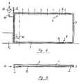
- FIGS. 1 to 3show the blank of an insulating glass pane, consisting of a first rectangular glass sheet 1 and a second rectangular glass sheet 2 of the same size, which are connected to one another by a thermoplastic spacer 3.
- the spacer 3can be formed in that a A strand of thermoplastic material is applied by means of a nozzle, as described in DE-44 33 749 A1, starting at a point 4 along the edge of the first glass sheet 1 until the beginning and end of the strand at point 4, forming one another Overlap sloping surface 5.
- the inclined surface 5is formed by gradually opening the mouth of the nozzle to its desired cross section at the beginning of the application process and gradually closing it at the end of the application process by means of a slide.
- the same slideis used to form two sections 6 and 7 with reduced width in the thermoplastic spacer 3, for which purpose the mouth cross section of the nozzle is temporarily narrowed by means of the slide. This narrowing does not happen suddenly, but gradually, so that the width of the strand 3, as shown in FIG. 3, does not decrease suddenly, but steadily to the reduced width b. If the second glass sheet 2 is then attached with slight pressure, a gap-shaped opening 8 results at these points, which is only closed when the insulating glass blank is pressed in order to create the air gap LZR desired in the finished insulating glass sheet between the two glass sheets 1 and 2 to obtain. This air gap LZR is smaller than the reduced width b of the strand 3 (see Figure 3).
- a tip 9 at one of the two lower corners of the second glass sheet 2is bent away from the first glass sheet 1 before the second glass sheet 2 is joined together with the first glass sheet 1 to form the insulating glass sheet blank.
- a gap-shaped opening 10leads around the corner of the insulating glass pane, the lower, horizontal section of which is covered by a horizontal conveyor 11, on which the blank stands, and the vertical section of which is covered by a gas filling nozzle 12 which a heavy gas is introduced into the interior of the insulating glass pane.
- the inflowing heavy gasprogressively displaces the air present in the interior from bottom to top through the two gap-shaped openings 8 located at the upper edge. If there were no opening 8 in section 7, it would a dead space is formed in the area of the upper corner there, which would be difficult to reach from the inflowing heavy gas, so that the air remaining in the dead space could not be displaced.
- the insulating glass blankis pressed in order to bring the two glass sheets 1 and 2 to their desired spacing LZR.
- the two openings 8are tightly closed by the compression of the spacer 3, the opening 10 being initially kept open by maintaining the bend in the gusset 9 until the desired distance LZR is reached outside the gusset 9. Only then is the bending of the second glass sheet 2 reversed and the target distance LZR is also reached in the region of the gusset 9. This procedure ensures that no overpressure can arise due to the compression of the spacer 3 in the interior of the insulating glass pane.
- the embodiment shown in Figures 4 and 5differs from the first embodiment in that instead of two shorter openings only a single long opening 8 is provided at the upper edge of the insulating glass blank, which is formed by the width of the spacer 3 in the corresponding Section was diminished.
- the second glass sheet 2is bent along its one vertical edge, as described in WO 92/01137, before the second glass sheet 2 is joined together with the first glass sheet 1 to form the insulating glass sheet blank. This results in a slit-shaped opening 10 which extends over the full vertical edge and extends a little further around the upper and lower corner.
- this gap-shaped openingis covered by the horizontal conveyor 11, on the vertical edge above the gas filling nozzle 12 by a special cover 13, which is interrupted by a suction line 14, which leads to a sensor 15 sensitive to oxygen.
- the heavy gas introduced into the interior of the insulating glass blank from the gas filling nozzle 12displaces the Air initially present through the long opening 8. A small part of the air and later the air / heavy gas mixture is drawn through line 14 to the sensor 15. As soon as it reports that the oxygen content has fallen below a certain lower limit, the gas exchange is ended and the insulating glass pane is pressed to its desired dimension LZR.
- FIGS. 6 and 7differs from the first exemplary embodiment in that, instead of a rectangular insulating glass pane, a semicircular model pane is assembled and filled with a heavy gas. Due to the semicircular contour, the formation of a dead space is less likely. In order to displace the air, an opening 8 extending over the apex of the model pane is sufficient, formed by a section with a reduced width of the spacer 3.
- the exemplary embodiment shown in FIGS. 8 and 9differs from the first exemplary embodiment in that a triangular insulating glass pane is assembled and filled with a heavy gas.
- the heavy gasis introduced through an opening 10 in the lower region of the oblique edge and the displacement of the air through an opening 8 in the upper region of the oblique edge of the insulating glass blank.
- the exemplary embodiment shown in FIGS. 10 and 11differs from the exemplary embodiment shown in FIGS. 8 and 9 in that a trapezoidal insulating glass pane is assembled and filled with a heavy gas.
- an opening 8is provided in the vicinity thereof, formed by a section with a reduced width of the spacer 3.
- Heavy gasis introduced as in the previous example through an opening 10, formed in the area of the lower left corner by bending a tip 9 of the second glass sheet 2.
Landscapes
- Engineering & Computer Science (AREA)
- Civil Engineering (AREA)
- Structural Engineering (AREA)
- Joining Of Glass To Other Materials (AREA)
- Securing Of Glass Panes Or The Like (AREA)
- Laminated Bodies (AREA)
- Building Environments (AREA)
- Compositions Of Macromolecular Compounds (AREA)
Abstract
Translated fromGerman
Description
Translated fromGermanDie Erfindung geht aus von einem Verfahren mit den im Oberbegriff des Anspruchs 1 angegebenen Merkmalen. Ein solches Verfahren ist aus der DE-44 33 749 A1 bekannt. Bei dem bekannten Verfahren wird ein thermoplastischer Strang, vorzugsweise auf Basis eines Polyisobutylens, in welches ein Feuchtigkeit bindendes Pulver, insbesondere Molekularsiebe, eingelagert ist, mittels einer Düse, welche einen definierten Mündungsquerschnitt hat, auf eine erste Glastafel entlang deren Randes aufgetragen, indem die Düse an dem Rand der Glastafel entlanggeführt wird und der Düse mittels einer Pumpe das thermoplastische Material aus einen Vorratsbehälter zugeführt wird. Anfang und Ende des Stranges werden über Schrägflächen miteinander verbunden. Nach dem Auftragen des thermoplastischen Stranges auf die erste Glastafel wird eine zweite Glastafel an die erste Glastafel angefügt, so daß die beiden Glastafeln durch den als Abstandhalter dienenden thermoplastischen Strang miteinander verklebt werden. Anschließend wird der gegenwärtige Abstand der beiden Glastafeln auf ein vorgegebenes Sollmaß verringert, entsprechend der vorgegebenen Solldicke der Isolierglasscheibe. Dabei wird der thermoplastische Strang gestaucht und eine lückenlose Hartung des Strangs an den beiden Glastafeln erreicht. Die auf der Außenseite des thermoplastischen Abstandhalters verbliebene Randfuge der Isolierglasscheibe wird anschließend mit einer aushärtenden Versiegelungsmasse, zumeist auf Polysulfidbasis, gefüllt, welche den Verbund der beiden Glastafeln dauerhaft sichert.The invention is based on a method with the features specified in the preamble of
Beim Stauchen des Abstandhalters wird der Rauminhalt des Isolierglasscheibenrohlings verringert. Damit in der Isolierglasscheibe nicht ein Überdruck entsteht, welcher auf die beiden Glastafeln und auf den thermoplastischen Abstandhalter einwirkt und sie zum Ausbeulen veranlassen kann, ist es bekannt, beim Verpressen des Isolierglasscheibenrohlings einen Druckausgleich zu ermöglichen. Die DE-34 04 006 A1 schlägt dazu vor, im thermoplastischen Abstandhalter zunächst eine Lücke zu belassen, welche erst nach dem Verpressen des Isolierglasscheibenrohlings auf sein Sollmaß geschlossen wird. Beim nachträglichen Schließen einer solchen Lücke ist es jedoch schwierig, die geforderte Dichtigkeit gegen Wasserdampfdiffusion zu erreichen. Die DE-42 31 424 A1 schlägt deshalb vor, von vornherein einen umlaufend geschlossenen thermoplastischen Abstandhalter zu bilden und einen Druckausgleich dadurch zu ermöglichen, daß man eine der beiden Glastafeln vor dem Verpressen des Isolierglasscheibenrohlings an einem Abschnitt ihres Randes von der gegenüberliegenden Glastafel wegbiegt, so daß beim Anfügen einer zweiten Glastafel an die erste Glastafel die zweite Glastafel nicht entlang ihres gesamten Umfangs mit der ersten Glastafel verklebt wird, sondern in dem Abschnitt, in welchem sie von der ersten Glastafel weggebogen ist, ein Spalt verbleibt. Diesen Spalt hält man während des Verpressens des Isolierglasscheibenrohlings zunächst offen, so daß durch ihn der Druckausgleich erfolgen kann. Erst wenn der Isolierglasscheibenrohling im nicht weggebogenen Bereich sein Sollmaß erreicht oder nahezu erreicht hat, wird die Biegung der zweiten Glastafel rückgängig gemacht und auch in jenem Abschnitt die Solldicke der Isolierglasscheibe hergestellt, wobei ein schädlicher Überdruck nicht mehr entstehen kann.When compressing the spacer, the volume of the insulating glass blank is reduced. So that there is no overpressure in the insulating glass pane, which acts on the two glass sheets and on the thermoplastic spacer and can cause them to bulge, it is known to enable pressure compensation when the insulating glass pane blank is pressed. DE-34 04 006 A1 proposes to initially leave a gap in the thermoplastic spacer, which gap is only closed after the insulating glass blank has been pressed to its desired size. When such a gap is subsequently closed, it is difficult to achieve the required tightness against water vapor diffusion. DE-42 31 424 A1 therefore proposes to form a circumferentially closed thermoplastic spacer from the outset and to enable pressure equalization by bending one of the two glass sheets away from the opposite glass sheet at a section of its edge before pressing the insulating glass blank that when a second glass sheet is attached to the first glass sheet, the second glass sheet is not glued to the first glass sheet along its entire circumference, but a gap remains in the section in which it is bent away from the first glass sheet. This gap is initially kept open during the pressing of the insulating glass blank, so that pressure equalization can take place through it. Only when the insulating glass blank in the area that has not been bent away has reached or has almost reached its nominal size, does the bending of the second glass sheet undone and also in that section the target thickness of the insulating glass pane was produced, whereby a harmful overpressure can no longer arise.
Aus der WO 89/11021 und aus der WO 92/01137 ist es bekannt, durch das Wegbiegen der einen Glastafel eines Isolierglasscheibenrohlings von der gegenüberliegenden Glastafel einen Zugang zum Innenraum des Isolierglasscheibenrohlings zu schaffen, um darin einen Austausch von Luft gegen ein Schwergas, z.B. Argon, vorzunehmen. Dabei wird das Schwergas bei ungefähr senkrecht stehender Isolierglasscheibe an einer tiefliegenden Öffnung eingeleitet und die Luft durch dieselbe Öffnung hindurch (EP 0 444 391 A1), durch eine der Einfüllöffnung gegenüberliegende Öffnung (WO 89/11021) oder durch eine am selben vertikalen Rand, an welchem die Einfüllöffnung vorgesehen wird, aber mit Abstand darüber liegenden Öffnung (WO 92/01137) verdrängt oder abgesaugt. Dabei ist es schwierig, die Luft vollständig aus dem Innenraum des Isolierglasscheibenrohlings zu verdrängen, weil sich insbesondere bei großformatigen Isolierglasscheiben Toträume ausbilden, welche von dem einströmenden Schwergas nicht erreicht werden, so daß ein vollständiger Gasaustausch praktisch unmöglich ist. Ein längere Zeit andauerndes Einleiten des Schwergases könnte den Restgehalt an Luft im Innenraum der Isolierglasscheibe zwar vermindern, wenn auch nicht vollständig beseitigen, verbietet sich aber aus Kostengründen, weil der Verbrauch des teuren Schwergases dadurch stark ansteigt.From WO 89/11021 and WO 92/01137 it is known to provide access to the interior of the insulating glass blank by bending the one glass sheet of an insulating glass blank from the opposite glass sheet in order to exchange air for a heavy gas, e.g. Argon. The heavy gas is introduced with the insulating glass pane standing approximately vertically at a deep opening and the air through the same opening (EP 0 444 391 A1), through an opening opposite the filling opening (WO 89/11021) or through a same vertical edge which the filling opening is provided, but displaced or suctioned off at a distance above it (WO 92/01137). It is difficult to displace the air completely from the interior of the insulating glass blank, because dead spaces form in particular in the case of large-sized insulating glass panes, which are not reached by the inflowing heavy gas, so that a complete gas exchange is practically impossible. A long-term introduction of the heavy gas could reduce the residual air content in the interior of the insulating glass pane, but not completely eliminate it, but it is prohibited for reasons of cost because the consumption of the expensive heavy gas increases sharply as a result.
Bei Isolierglasscheiben, die anstelle eines thermoplastischen Abstandhalters einen metallischen Abstandhalterrahmen haben, welcher beidseits mit Klebstoff beschichtet ist, um ihn mit den beiden Glastafeln der Isolierglasscheibe zu verbinden, ist es aus der DE-42 02 612 C2 bekannt, den Abstandhalterrahmen vor dem Verbinden mit den beiden Glastafeln stellenweise zunächst nicht mit Klebstoff zu beschichten oder ihn zwar umlaufend mit Klebstoff zu beschichten, diesen aber stellenweise wieder zu entfernen, um auf diese Weise Öffnungen im Isolierglasscheibenrohling zu erzeugen, durch die hindurch ein Gasaustausch vorgenommen werden kann; diese Öffnungen werden nach vollzogenem Gasaustausch durch Einspritzen von weiterem Klebstoff verschlossen. Diese Vorgehensweise ist arbeitsaufwendig und hat den Nachteil, daß es schwierig ist, die sehr schmalen Öffnungen mit der erforderlichen Dichtigkeit nachträglich zu verschließen; wird der Klebstoff mit zu hohem Druck eingespritzt, kann er unkontrolliert in den Innenraum gelangen, wird er mit geringerem Druck eingespritzt, füllt er die schmalen Öffnungen nicht aus; obendrein kann auf die zu verklebenden Flächen kaum Druck ausgeübt werden. Im übrigen läßt sich eine solche Vorgehensweise nur bei metallischen Abstandhaltern, nicht aber bei thermoplastischen Abstandhaltern durchführen.In insulating glass panes, which have a metallic spacer frame instead of a thermoplastic spacer, which is coated on both sides with adhesive to connect it to the two glass panels of the insulating glass pane, it is known from DE-42 02 612 C2, the spacer frame before connecting to the Do not initially coat either of the two glass panels with adhesive or coat it with adhesive all around, but remove it in places in order to create openings in the insulating glass blank through which gas exchange occurs can be made; these openings are closed after the gas has been exchanged by injecting further adhesive. This procedure is labor-intensive and has the disadvantage that it is difficult to subsequently close the very narrow openings with the required tightness; if the adhesive is injected with too high pressure, it can get into the interior uncontrollably, if it is injected with less pressure, it does not fill the narrow openings; on top of that, hardly any pressure can be exerted on the surfaces to be glued. Otherwise, such a procedure can only be carried out with metallic spacers, but not with thermoplastic spacers.
Der vorliegenden Erfindung liegt dieAufgabe zugrunde, einen Weg aufzuzeigen, wie beim Herstellen von Isolierglasscheiben mit thermoplastischem Abstandhalter das Entweichen von Luft aus dem Innenraum des Isolierglasscheibenrohlings und das anschließende dichte Verschließen des Innenraums auf einfache Weise erfolgen können.The present invention has for itsobject to show a way how in the manufacture of insulating glass panes with thermoplastic spacers, the escape of air from the interior of the insulating glass blank and the subsequent tight sealing of the interior can be done in a simple manner.
Diese Aufgabe wird erfindungsgemäß gelöst durch ein Verfahren mit den im Patentanspruch 1 angegebenen Merkmalen. Vorteilhafte Weiterbildungen der Erfindung sind Gegenstand der abhängigen Ansprüche.This object is achieved by a method with the features specified in
Die Erfindung erreicht ihr Ziel auf verblüffend elegante Weise indem der thermoplastische Strang, mit welchem der Abstandhalter gebildet wird, abschnittsweise mit verminderter Breite gebildet und auf die Glastafel aufgetragen wird, wobei die verminderte Breite größer ist als die Sollbreite (Sollmaß), welche der Abstandhalter in der fertigen Isolierglasscheibe haben soll. Als die Breite des Abstandhalters bzw. des den Abstandhalter bildenden thermoplastischen Stranges wird der Abstand seiner beiden den Glastafeln zugewandten Flächen bezeichnet. Das Sollmaß stimmt deshalb mit dem Abstand der beiden Glastafeln in der fertigen Isolierglasscheibe überein; dieser Abstand wird auch als Luftzwischenraum ( LZR) bezeichnet.The invention achieves its goal in an astonishingly elegant manner in that the thermoplastic strand with which the spacer is formed is formed in sections with a reduced width and applied to the glass sheet, the reduced width being greater than the nominal width (nominal dimension) which the spacer in should have the finished insulating glass pane. The width of the spacer or of the thermoplastic strand forming the spacer is the distance between its two surfaces facing the glass sheets. The target dimension therefore corresponds to the distance between the two glass sheets in the finished insulating glass pane; this distance is also known as the air gap (LZR).
Dadurch, daß die abschnittsweise verminderte Breite des Strangs größer ist als das Sollmaß, wird sichergestellt, daß der Strang beim Verpressen des Isolierglasscheibenrohlings auf das Sollmaß der Isolierglasscheibe auf jeden Fall noch gestaucht wird und sich auch in den Abschnitten mit verminderter Breite dicht mit den beiden Glastafeln verbindet.Characterized in that the sectionally reduced width of the strand is larger than the nominal size, it is ensured that the strand is still compressed in any case when the insulating glass blank is pressed onto the nominal size of the insulating glass pane and that the sections with reduced width are also tightly sealed with the two glass panels connects.
Die Erfindung hat wesentliche Vorteile:
- ◆ Das Auftragen des Strangs mit abschnittsweise verminderter Breite erfordert im Vergleich zum Aufbringen eines thermoplastischen Strangs mit konstanter Breite keinen zusätzlichen apparativen Aufwand und keine zusätzliche Arbeitszeit.
- ◆ Das Verpressen des Isolierglasscheibenrohlings erfordert keine Änderungen gegenüber dem Stand der Technik.
- ◆ Die Taktzeit für das Herstellen einer Isolierglasscheibe nach dem erfindungsgemäßen Verfahren wird gegenüber dem Stand der Technik nicht verlängert, sondern bleibt gleich oder wird sogar verkürzt, weil für das dichte Verschließen der abschnittsweise zunächst vorliegenden Öffnungen zwischen dem thermoplastischen Strang und einer der Glastafeln kein besonderer Arbeitsgang benötigt wird.
- ◆ Das erfindungsgemäße Verfahren erlaubt ein rationelleres Herstellen von Isolierglasscheiben mit thermoplastischem Abstandhalter.
- ◆ Durch das abschnittsweise Vermindern der Breite des thermoplastischen Strangs können Öffnungen für einen Luftaustritt bzw. einen Gasaustausch ohne Schwierigkeiten auf das Format der Isolierglasscheibe abgestimmt und so positioniert werden, wie es für einen Luttaustritt bzw. für einen Gasaustausch besonders günstig ist. Insbesondere können die Abschnitte mit verminderter Breite dort gebildet werden, wo erfahrungsgemäß eine Neigung zur Bildung von Toträumen besteht, die vom Schwergas nicht oder nur zögernd durchströmt werden, so daß sich solche Toträume erfindungsgemäß leicht vermeiden lassen.
- ◆ Besonders günstig ist das erfindungsgemäße Verfahren beim Herstellen von Isolierglasscheiben mit thermoplastischem Abstandhalter, welche mit einem Schwergas gefüllt werden sollen. Dadurch, daß sich Toträume, aus denen sich die Luft vom Schwergas nicht oder nur sehr zögernd verdrängen läßt, leicht vermeidbar sind, wird die Möglichkeit eröffnet, den Gasaustausch
- ◆ schneller,
- ◆ vollständiger und
- ◆ mit weniger Schwergasverbrauch als bisher durchzuführen.
- ◆ Den thermoplastischen Strang abschnittsweise mit verminderter Breite auszubilden, ist aber auch dann schon vorteilhaft, wenn kein Gasaustausch durchgeführt werden soll, denn die im Isolierglasscheibenrohling zunächst vorhandenen Öffnungen ermöglichen beim Verpressen des Isolierglases zeitweise ein Entweichen von Luft und wirken so einem Druckanstieg in der Isolierglasscheibe beim Verpressen entgegen, ohne den dichten Verbund der Isolierglasscheibe zu gefährden.
- ◆ The application of the strand with reduced width in sections does not require any additional equipment and no additional working time compared to the application of a thermoplastic strand with a constant width.
- ◆ The pressing of the insulating glass blank does not require any changes compared to the state of the art.
- ◆ The cycle time for producing an insulating glass pane according to the method according to the invention is not extended compared to the prior art, but remains the same or is even shortened, because for the tight sealing of the openings that are initially present in sections between the thermoplastic strand and one of the glass sheets, no special operation is needed.
- ◆ The method according to the invention allows a more efficient production of insulating glass panes with a thermoplastic spacer.
- ◆ By reducing the width of the thermoplastic strand in sections, openings for an air outlet or a gas exchange can be matched to the format of the insulating glass pane without difficulty and positioned in the same way as for a ventilation outlet or for one Gas exchange is particularly cheap. In particular, the sections with reduced width can be formed where experience has shown that there is a tendency to form dead spaces which are not or only hesitantly flowed through by the heavy gas, so that such dead spaces can easily be avoided according to the invention.
- ◆ The method according to the invention is particularly favorable when producing insulating glass panes with thermoplastic spacers which are to be filled with a heavy gas. The fact that dead spaces from which the air cannot be displaced by the heavy gas, or only with great hesitation, can easily be avoided, opens up the possibility of gas exchange
- ◆ faster,
- ◆ more complete and
- ◆ with less heavy gas consumption than before.
- ◆ Forming the thermoplastic strand in sections with a reduced width is also advantageous even if no gas exchange is to be carried out, because the openings initially present in the insulating glass blank allow air to escape temporarily when the insulating glass is pressed and thus act to increase the pressure in the insulating glass pane Press against it without jeopardizing the tight bond of the insulating glass pane.
Der thermoplastische Strang könnte vorgefertigt, dabei in Abständen mit verminderter Breite ausgebildet, auf Rollen zwischengespeichert und dann von der Rolle verarbeitet werden, z.B. so, wie es in der DE 34 04 006 beschrieben ist. Günstiger ist es, den thermoplastischen Strang unmittelbar auf die erste Glastafel zu extrudieren und beim Extrudieren abschnittsweise mit der verminderten Breite auszubilden. Verfahren und Vorrichtungen zum unmittelbaren Extrudieren eines thermoplastischen Strangs auf eine Glastafel sind in der EP 0 171 309 B2, in der DE 43 35 671 A1, in der DE 43 35 673 A1 und in der DE 44 33 749 A1 offenbart, auf deren Inhalt hier zur Vermeidung von Wiederholungen ausdrücklich Bezug genommen wird. Der thermoplastische Strang kann während des Extrudierens ganz einfach z. B. dadurch abschnittsweise mit verminderter Breite ausgebildet werden, daß er mittels einer Düse erzeugt wird, deren lichte Breite, z.B. durch einen Schieber, zeitweise verringert wird. Eine solche Düse offenbart die DE-44 33 749 A1. Eine andere Möglichkeit, den Strang während des Extrudierens abschnittsweise mit verminderter Breite auszubilden, besteht darin, die Düse, mittels welcher er erzeugt wird, zeitweise mit erhöhter Geschwindigkeit entlang des Randes der ersten Glastafel zu bewegen, ohne zugleich den Durchsatz des thermoplastischen Materials durch die Düse im selben Ausmaß zu erhöhen. Eine andere Möglichkeit besteht darin, zeitweise den Durchsatz durch die Düse zu drosseln, während diese entlang des Randes der ersten Glastafel bewegt wird, ohne zugleich die Geschwindigkeit der Düse im selben Ausmaß zu verringern.The thermoplastic strand could be prefabricated, formed at intervals of reduced width, temporarily stored on rolls and then processed from the roll, for example as described in DE 34 04 006. It is cheaper to extrude the thermoplastic strand directly onto the first glass sheet and to form it in sections with the reduced width during extrusion. Methods and devices for the direct extrusion of a thermoplastic strand onto a glass sheet are disclosed in EP 0 171 309 B2, in DE 43 35 671 A1, in DE 43 35 673 A1 and in DE 44 33 749 A1, the content of which is expressly referred to here to avoid repetition. The thermoplastic strand can be easily z. B. be formed in sections with a reduced width in that it is generated by means of a nozzle, the clear width, for example by a slide, is temporarily reduced. DE 44 33 749 A1 discloses such a nozzle. Another possibility of forming the strand in sections with reduced width during extrusion is to move the nozzle, by means of which it is produced, at times with increased speed along the edge of the first glass sheet, without at the same time the throughput of the thermoplastic material through the nozzle increase to the same extent. Another possibility is to temporarily reduce the throughput through the nozzle while it is being moved along the edge of the first glass sheet, without at the same time reducing the speed of the nozzle to the same extent.
In allen diesen Fällen läßt sich die Lage der Öffnung oder der Öffnungen, die auf diese Weise im Isolierglasscheibenrohling gebildet werden, individuell auf das Format und auf die Umrißgestalt der Isolierglasscheiben abstimmen und optimieren.In all these cases, the position of the opening or the openings which are formed in this way in the insulating glass blank can be individually matched and optimized to the format and the outline shape of the insulating glass panes.
Beim Bilden eines Abschnitts mit verminderter Breite wird die Breite vorzugsweise zunächst allmählich vermindert, dann ein Stück weit gleichbleibend gehalten und zum Schluß allmählich wieder erhöht, um stetige Übergänge zwischen den Abschnitten mit verminderter Breite und den Abschnitten mit unverminderter Breite zu erhalten. Solche stetigen Übergänge sind günstiger für ein unterbrechungsfreies Verkleben des Stranges mit den Glastafeln. Bei einer stufenweisen Verringerung müßten die Stufen an die Fließfähigkeit des thermoplastischen Materials beim Verpressen des Isolierglasscheibenrohlings abgestimmt werden.When forming a reduced width section, the width is preferably first gradually reduced, then kept a little constant, and then gradually increased again at the end in order to obtain smooth transitions between the reduced width sections and the undiminished width sections. Such continuous transitions are cheaper for an uninterrupted gluing of the strand to the glass panels. In the case of a gradual reduction, the steps would have to be matched to the flowability of the thermoplastic material when pressing the insulating glass pane blank.
Der Übergang von der vollen Breite des thermoplastischen Strangs zur verminderten Breite erfolgt zweckmäßigerweise über eine Länge von 10 mm bis 40 mm, vorzugsweise über eine Länge von 30 mm ± 5 mm. Das Ausmaß der Verminderung der Breite muß kleiner sein als das Stauchmaß. Als Stauchmaß wird hier der Unterschied zwischen der unverminderten Breite des Strangs und seinem Sollmaß in der fertigen Isolierglasscheibe verstanden. Das Maß, um welches die Breite des Stranges vermindert wird, ist zweckmäßigerweise nicht größer als das 0,6-fache des Stauchmaßes, um auch in dem Abschnitt mit verminderter Breite noch eine für ein dichtes Verbinden des Strangs mit den beiden Glastafeln ausreichende Stauchung des Strangs zu erzielen; andererseits beträgt die Verminderung der Breite des Strangs zweckmäßigerweise nicht weniger als das 0,3-fache des Stauchmaßes, um noch eine hinreichende Weite der Öffnungen im Isolierglasscheibenrohling zu erhalten. Vorzugsweise beträgt das Maß, um welche die Breite des Strangs vermindert wird, das 0,4-fache bis zum 0,5-fachen des Stauchmaßes. Das Stauchmaß seinerseits wird zweckmäßigerweise in Abhängigkeit vom vorgesehenen Luftzwischenraum der Isolierglasscheibe gewählt, welcher mit dem vorstehend definierten Sollmaß übereinstimmt. Vorzugsweise wird als Stauchmaß das 0,1-fache bis 0,2-fache des Sollmaßes gewählt.The transition from the full width of the thermoplastic strand to the reduced width expediently takes place over a length of 10 mm to 40 mm, preferably over a length of 30 mm ± 5 mm. The amount of reduction in width must be less than the amount of compression. Here, the compression dimension is understood to be the difference between the undiminished width of the strand and its nominal size in the finished insulating glass pane. The amount by which the width of the strand is reduced is expediently not greater than 0.6 times the upset dimension, in order also in the section with reduced width to compress the strand sufficiently for a tight connection of the strand to the two glass sheets to achieve; on the other hand, the reduction in the width of the strand is expediently not less than 0.3 times the compression dimension in order to obtain a sufficient width of the openings in the insulating glass blank. The amount by which the width of the strand is reduced is preferably 0.4 to 0.5 times the amount of compression. For its part, the compression dimension is expediently chosen as a function of the air gap provided for the insulating glass pane, which corresponds to the target dimension defined above. Preferably 0.1 to 0.2 times the nominal size is selected as the compression size.
Für Zwecke der Erfindung wird im thermoplastischen Strang wenigstens ein Abschnitt mit verminderter Breite pro Isolierglasscheibe vorgesehen. Bei größeren Isolierglasscheiben empfiehlt es sich, zwei oder mehr als zwei Abschnitte mit verminderter Breite in dem auf die erste Glastafel aufgetragenen Strang vorzusehen.For purposes of the invention, at least one section with reduced width per insulating glass pane is provided in the thermoplastic strand. In the case of larger insulating glass panes, it is advisable to provide two or more than two sections of reduced width in the strand applied to the first glass sheet.
Zum Herstellen von Isolierglasscheiben, die mit einem von Luft verschiedenen Gas, insbesondere mit einem Schwergas gefüllt sind, kann das Verfahren nach der Erfindung in der Weise angewendet werden, daß durch eine erfindungsgemäß gebildete Öffnung des Isolierglasscheibenrohlings das Schwergas eingeleitet und aus einer oder mehreren weiteren Öffnungen die vom Schwergas verdrängte Luft, in weiterer Folge auch ein Luft-Schwergas-Gemisch, verdrängt wird, wobei das Verdrängen durch Absaugen unterstützt werden kann. Ist der Gasaustausch vollzogen, was durch eine Sonde festgestellt werden kann, welcher die den den Isolierglasscheibenrohling verlassende Gasmischung zugeführt wird, dann muß der Rohling nur noch auf sein Sollmaß verpreßt werden, um die Isolierglasscheibe dicht zu verschließen. Es ist aber auch möglich, eine größere Öffnung für das Einleiten des Schwergases dadurch zu bilden, daß in an sich bekannter Weise eine der Glastafeln zunächst an der gegenüberliegenden Glastafel stellenweise weggebogen wird (WO 89/11021), vorzugsweise dadurch, daß die eine Glastafel längs eines ihrem Ränder abgebogen wird, wie in der WO 92/01137 offenbart, oder auch dadurch, daß die eine Glastafel an ihrer einen Ekke weggebogen wird, wie in der EP 0444 391 A1 offenbart, auf welche hiermit zur Vermeidung von Wiederholungen ausdrücklich bezuggenommen wird. Das Ausströmen der Luft bzw. eines Luft-Schwergas-Gemisches aus dem Innenraum des Isolierglasscheibenrohlings kann teilweise durch die durch das Wegbiegen der einen Glastafel gebildete Öffnung und/oder durch die weiteren Öffnungen erfolgen, welche durch das abschnittsweise Vermindern der Dicke des thermoplastischen Abstandhalters gebildet sind. Auf diese Weise läßt sich die Luft besonders rasch und vollständig und mit sparsamstem Schwergasverbrauch aus der Isolierglasscheibe verdrängen. Das Wegbiegen einer Glastafel in Kombination mit den weiteren, durch abschnittsweises Vermindern der Breite des thermoplastischen Abstandhalters gebildeten Öffnungen ist nicht nur vorteilhaft, weil dadurch ein größerer Querschnitt für das Einleiten des Schwergases gebildet werden kann, sondern ist auch vorteilhaft für den Druckabbau im Isolierglasscheibenrohling im Verlauf des nach dem Gasaustausch erfolgenden Verpressens auf sein Sollmaß, welches vorzugsweise zuerst außerhalb des weggebogenen Bereichs der einen Glastafel erfolgt; vorzugsweise wird erst die Biegung der "zweiten" Glastafel rückgängig gemacht, welche, während sie sich dem Abstandhalter annähert, das restliche überschüssige Gas noch aus dem Innenraum der Isolierglasscheibe verdrängen kann und den Innenraum erst dann dicht verschließt, wenn dieser praktisch sein endgültiges Volumen erreicht hat.To produce insulating glass panes which are filled with a gas other than air, in particular with a heavy gas, the method according to the invention can be used in such a way that the heavy gas is introduced through an opening of the insulating glass pane blank formed according to the invention and from one or more further openings the air displaced by the heavy gas, subsequently also an air / heavy gas mixture, is displaced, the displacement being able to be supported by suction. Once the gas exchange has taken place, which can be determined by a probe to which the gas mixture leaving the insulating glass blank is fed, then the blank only has to be pressed to its nominal size in order to tightly close the insulating glass pane. However, it is also possible to form a larger opening for introducing the heavy gas in that, in a manner known per se, one of the glass sheets is first bent away in places on the opposite glass sheet (WO 89/11021), preferably in that the one glass sheet is elongated one of its edges is bent, as disclosed in WO 92/01137, or also in that the one glass sheet is bent away at its one corner, as disclosed in EP 0444 391 A1, to which express reference is hereby made to avoid repetition. The outflow of air or an air-heavy gas mixture from the interior of the insulating glass blank can take place partly through the opening formed by bending away the one glass sheet and / or through the further openings, which are formed by reducing the thickness of the thermoplastic spacer in sections . In this way, the air can be displaced from the insulating glass pane particularly quickly and completely and with the most economical use of heavy gas. The bending away of a glass sheet in combination with the further openings formed by reducing the width of the thermoplastic spacer in sections is not only advantageous because it can form a larger cross section for the introduction of the heavy gas, but is also advantageous for the pressure reduction in the insulating glass blank during the course the pressing which takes place after the gas exchange to its desired dimension, which is preferably carried out first outside the bent-away area of the one glass sheet; preferably the curvature of the "second" glass sheet is reversed, which, as it approaches the spacer, can still displace the remaining excess gas from the interior of the insulating glass pane and only then tightly closes the interior when it has practically reached its final volume .
Ausführungsbeispiele der Erfindung werden anhand der beigefügten Zeichnungen erläutert. Gleiche oder einander entsprechende Teile sind in den verschiedenen Zeichnungen mit übereinstimmenden Bezugszahlen bezeichnet.
Figur 1- zeigt den Rohling einer rechteckigen Isolierglasscheibe mit zwei erfindungsgemäß gebildeten Öffnungen in einer Seitenansicht,
Figur 2- zeigt den
Rohling aus Figur 1 in der Draufsicht, Figur 3- zeigt als vergrößertes Detail einen Ausschnitt aus der
Draufsicht von Figur 2, Figur 4- zeigt den Rohling einer rechteckigen Isolierglasscheibe in einer Seitenansicht mit einer einzigen erfindungsgemäß gebildeten Öffnung,
Figur 5- zeigt die
Isolierglasscheibe aus Figur 4 in der Draufsicht, - Figur 6
- zeigt eine halbrunde Modellscheibe in einer Seitenansicht mit einer einzigen erfindungsgemäß gebildeten Öffnung,
Figur 7- zeigt die Modellscheibe aus Figur 6 in der Draufsicht,
Figur 8- zeigt eine dreieckige Modellscheibe in einer Seitenansicht mit einer einzigen erfindungsgemäß gebildeten Öffnung,
Figur 9- zeigt die
Modellscheibe aus Figur 8 in der Draufsicht, Figur 10- zeigt eine trapezförmige Modellscheibe in einer Seitenansicht mit einer einzigen erfindungsgemäß gebildeten Öffnung, und
Figur 11- zeigt die
Modellscheibe aus Figur 10 in der Draufsicht.
- Figure 1
- shows the blank of a rectangular insulating glass pane with two openings formed according to the invention in a side view,
- Figure 2
- shows the blank from Figure 1 in plan view,
- Figure 3
- shows an enlarged detail of a detail from the top view of Figure 2,
- Figure 4
- shows the blank of a rectangular insulating glass pane in a side view with a single opening formed according to the invention,
- Figure 5
- 4 shows a top view of the insulating glass pane from FIG. 4,
- Figure 6
- shows a semicircular model disc in a side view with a single opening formed according to the invention,
- Figure 7
- 6 shows the model pane from FIG. 6 in a top view,
- Figure 8
- shows a triangular model pane in a side view with a single opening formed according to the invention,
- Figure 9
- 8 shows the model pane from FIG. 8 in a top view,
- Figure 10
- shows a trapezoidal model disc in a side view with a single opening formed according to the invention, and
- Figure 11
- shows the model disk of Figure 10 in plan view.
Die Figuren 1 bis 3 zeigen den Rohling einer Isolierglasscheibe, bestehend aus einer ersten rechteckigen Glastafel 1 und einer zweiten rechteckigen, gleich großen Glastafel 2, welche durch einen thermoplastischen Abstandhalter 3 miteinander verbunden sind. Der Abstandhalter 3 kann dadurch gebildet sein, daß ein Strang aus thermoplastischem Material mittels einer Düse, wie in der DE-44 33 749 A1 beschrieben, beginnend an einer Stelle 4 längs des Randes der ersten Glastafel 1 auf diese aufgetragen wird, bis Anfang und Ende des Strangs an der Stelle 4 einander unter Bildung einer Schrägfläche 5 überlappen. Die Schrägfläche 5 wird dadurch gebildet, daß mittels eines Schiebers die Mündung der Düse zu Beginn des Applikationsvorganges allmählich auf ihren Sollquerschnitt geöffnet und zum Schluß des Applikationsvorganges allmählich geschlossen wird. Derselbe Schieber wird eingesetzt, um in dem thermoplastischen Abstandhalter 3 zwei Abschnitte 6 und 7 mit verminderter Breite auszubilden, wozu der Mündungsquerschnitt der Düse mittels des Schiebers zeitweise verengt wird. Diese Verengung geschieht nicht schlagartig, sondern allmählich, so daß sich die Breite des Strangs 3, wie in Figur 3 dargestellt, nicht schlagartig, sondern stetig auf die verminderte Breite b verringert. Wird danach die zweite Glastafel 2 mit leichtem Druck angefügt, so ergibt sich an diesen Stellen eine spaltförmige Öffnung 8, welche erst dann geschlossen wird, wenn der Isolierglasscheibenrohling verpreßt wird, um den in der fertigen Isolierglasscheibe gewünschten Luftzwischenraum LZR zwischen den beiden Glastafeln 1 und 2 zu erhalten. Dieser Luftzwischenraum LZR ist kleiner als die reduzierte Breite b des Stranges 3 (siehe Figur 3).FIGS. 1 to 3 show the blank of an insulating glass pane, consisting of a first
Um die Isolierglasscheibe mit einem Schwergas füllen zu können, wird ein Zipfel 9 an einer der beiden unteren Ecken der zweiten Glastafel 2 von der ersten Glastafel 1 weggebogen, bevor die zweite Glastafel 2 mit der ersten Glastafel 1 zum Isolierglasscheibenrohling zusammengefügt wird. Auf diese Weise ergibt sich im Bereich des Zwickels eine um die Ecke der Isolierglasscheibe herumführende spaltförmige Öffnung 10, deren unterer, waagerechter Abschnitt durch einen Waagerechtförderer 11 abgedeckt wird, auf welchem der Rohling steht, und dessen vertikaler Abschnitt durch eine Gasfülldüse 12 abgedeckt wird, durch welche ein Schwergas in den Innenraum der Isolierglasscheibe eingeleitet wird. Das einströmende Schwergas verdrängt die im Innenraum vorhandene Luft fortschreitend von unten nach oben durch die beiden am oberen Rand liegenden spaltförmigen Öffnungen 8. Würde sich im Abschnitt 7 keine Öffnung 8 befinden, würde sich im Bereich der dortigen oberen Ecke ein Totraum bilden, welcher von dem einströmenden Schwergas nur schwer erreicht würde, so daß die im Totraum verbleibende Luft nicht verdrängt werden könnte. Dadurch, daß dort erfindungsgemäß jedoch eine Öffnung 8 vorhanden ist, kann die Luft praktisch vollständig und rasch gegen das Schwergas ausgetauscht werden. Ist der Austausch vollzogen, wird der Isolierglasscheibenrohling verpreßt, um die beiden Glastafeln 1 und 2 auf ihren Sollabstand LZR zu bringen. Die beiden Öffnungen 8 werden durch die Stauchung des Abstandhalters 3 dicht verschlossen, wobei die Öffnung 10 durch Aufrechterhalten der Biegung im Zwickel 9 zunächst offengehalten wird, bis außerhalb des Zwickels 9 der Sollabstand LZR erreicht ist. Erst danach wird die Biegung der zweiten Glastafel 2 rückgängig gemacht und auch im Bereich des Zwickels 9 der Sollabstand LZR erreicht. Bei dieser Vorgehensweise ist sichergestellt, daß durch das Stauchen des Abstandhalters 3 im Innenraum der Isolierglasscheibe kein Überdruck entstehen kann.In order to be able to fill the insulating glass pane with a heavy gas, a
Das in den Figuren 4 und 5 dargestellte Ausführungsbeispiel unterscheidet sich vom ersten Ausführungsbeispiel darin, daß am oberen Rand des Isolierglasscheibenrohlings anstelle von zwei kürzeren Öffnungen nur eine einzige lange Öffnung 8 vorgesehen ist, welche dadurch gebildet ist, daß die Breite des Abstandhalters 3 in dem entsprechenden Abschnitt vermindert wurde. Um die Isolierglasscheibe mit einem Schwergas füllen zu können, wird die zweite Glastafel 2 längs ihres einen vertikalen Randes abgebogen, wie in der WO 92/01137 beschrieben, bevor die zweite Glastafel 2 mit der ersten Glastafel 1 zum Isolierglasscheibenrohling zusammengefügt wird. Dadurch ergibt sich eine spaltförmige Öffnung 10, welche sich über den vollen vertikalen Rand erstreckt und noch ein Stück weit um die obere und untere Ecke herumragt. Am unteren Rand des Rohlings wird diese spaltförmige Öffnung durch den Waagerechtförderer 11 abgedeckt, am vertikalen Rand oberhalb der Gasfülldüse 12 durch eine besondere Abdeckung 13, welche von einer Absaugleitung 14 unterbrochen ist, welche zu einem auf Sauerstoff empfindlichen Meßfühler 15 führt. Das von der Gasfülldüse 12 in den Innenraum des Isolierglasscheibenrohlings eingeleitete Schwergas verdrängt die im Innenraum zunächst vorhandene Luft durch die lange Öffnung 8. Ein kleiner Teil der Luft und später des Luft-Schwergas-Gemisches wird durch die Leitung 14 zum Meßfühler 15 gesaugt. Sobald dieser meldet, daß der Sauerstoffgehalt eine bestimmte untere Grenze unterschritten hat, wird der Gasaustausch beendet und die Isolierglasscheibe auf ihr Sollmaß LZR verpreßt.The embodiment shown in Figures 4 and 5 differs from the first embodiment in that instead of two shorter openings only a single
Das in den Figuren 6 und 7 dargestellte Ausführungsbeispiel unterscheidet sich von dem ersten Ausführungsbeispiel darin, daß anstelle einer rechteckigen Isolierglasscheibe eine halbrunde Modellscheibe zusammengebaut und mit einem Schwergas gefüllt wird. Infolge der halbrunden Kontur ist die Bildung eines Totraums weniger wahrscheinlich. Um die Luft zu verdrängen, genügt eine sich über den Scheitel der Modellscheibe hinweg erstreckende Öffnung 8, gebildet durch einen Abschnitt mit verminderter Breite des Abstandhalters 3.The exemplary embodiment shown in FIGS. 6 and 7 differs from the first exemplary embodiment in that, instead of a rectangular insulating glass pane, a semicircular model pane is assembled and filled with a heavy gas. Due to the semicircular contour, the formation of a dead space is less likely. In order to displace the air, an
Das in den Figuren 8 und 9 dargestellte Ausführungsbeispiel unterscheidet sich vom ersten Ausführungsbeispiel darin, daß eine dreieckige Isolierglasscheibe zusammengebaut und mit einem Schwergas gefüllt wird. In diesem Fall erfolgt die Einleitung des Schwergases durch eine Öffnung 10 im unteren Bereich des schräg verlaufenden Randes und das Verdrängen der Luft durch eine Öffnung 8 im oberen Bereich des schräg verlaufenden Randes des Isolierglasscheibenrohlings.The exemplary embodiment shown in FIGS. 8 and 9 differs from the first exemplary embodiment in that a triangular insulating glass pane is assembled and filled with a heavy gas. In this case, the heavy gas is introduced through an
Das in den Figuren 10 und 11 dargestellte Ausführungsbeispiel unterscheidet sich von dem in den Figuren 8 und 9 dargestellten Ausführungsbeispiel dahingehend, daß eine trapezförmige Isolierglasscheibe zusammengebaut und mit einem Schwergas gefüllt wird. Um das Ausbilden eines Totraums im Bereich der rechten oberen Ecke zu vermeiden, ist in deren Nähe eine Öffnung 8, gebildet durch einen Abschnitt mit verminderter Breite des Abstandhalters 3, vorgesehen. Das Einleiten von Schwergas erfolgt wie im vorhergehenden Beispiel durch eine Öffnung 10, gebildet im Bereich der linken unteren Ecke durch Abbiegen eines Zipfels 9 der zweiten Glastafel 2.The exemplary embodiment shown in FIGS. 10 and 11 differs from the exemplary embodiment shown in FIGS. 8 and 9 in that a trapezoidal insulating glass pane is assembled and filled with a heavy gas. In order to avoid the formation of a dead space in the area of the upper right corner, an
Claims (17)
Translated fromGermanApplications Claiming Priority (2)
| Application Number | Priority Date | Filing Date | Title |
|---|---|---|---|
| DE19617198 | 1996-04-29 | ||
| DE19617198ADE19617198A1 (en) | 1996-04-29 | 1996-04-29 | Process for the production of insulating glass panes with thermoplastic spacers |
Publications (3)
| Publication Number | Publication Date |
|---|---|
| EP0805254A2true EP0805254A2 (en) | 1997-11-05 |
| EP0805254A3 EP0805254A3 (en) | 1999-09-22 |
| EP0805254B1 EP0805254B1 (en) | 2002-11-06 |
Family
ID=7792839
Family Applications (1)
| Application Number | Title | Priority Date | Filing Date |
|---|---|---|---|
| EP97105195AExpired - LifetimeEP0805254B1 (en) | 1996-04-29 | 1997-03-27 | Method of manufacturing insulating glass panels with thermoplastic spacer |
Country Status (3)
| Country | Link |
|---|---|
| EP (1) | EP0805254B1 (en) |
| AT (1) | ATE227390T1 (en) |
| DE (2) | DE19617198A1 (en) |
Cited By (15)
| Publication number | Priority date | Publication date | Assignee | Title |
|---|---|---|---|---|
| EP1002925A2 (en) | 1998-11-19 | 2000-05-24 | Peter Lisec | Assembly method for insulating glazing units with a thermoplastic spacer |
| FR2861120A1 (en)* | 2003-10-16 | 2005-04-22 | Patrice Cardot | Double-glazed panel manufacturing procedure uses spacer of thermoplastic resin film that is heated to stick glass panes together after evacuating air |
| WO2008107612A3 (en)* | 2007-02-06 | 2008-12-18 | Saint Gobain | Spacer frame for an insulating window element comprising at least one convex pane |
| WO2011009554A1 (en)* | 2009-07-24 | 2011-01-27 | Bystronic Lenhardt Gmbh | Method for producing an insulating glass pane |
| US8101251B2 (en) | 2006-07-03 | 2012-01-24 | Dow Corning Corporation | Chemically curing all-in-one warm edge spacer and seal |
| US8866590B2 (en) | 2006-05-30 | 2014-10-21 | Dow Corning | Insulating glass unit with an electronic device and process for its production |
| US9736028B2 (en) | 2006-12-29 | 2017-08-15 | Kip Prod P1 Lp | System and method for providing network support services and premises gateway support infrastructure |
| US9924235B2 (en) | 2006-12-29 | 2018-03-20 | Kip Prod P1 Lp | Display inserts, overlays, and graphical user interfaces for multimedia systems |
| EP3357884A4 (en)* | 2015-09-29 | 2018-10-31 | Panasonic Intellectual Property Management Co., Ltd. | Glass panel unit manufacturing method and glass window manufacturing method |
| US10385609B2 (en) | 2014-01-28 | 2019-08-20 | Lisec Austria Gmbh | Method and device for producing thermoplastic spacers |
| US10403394B2 (en) | 2006-12-29 | 2019-09-03 | Kip Prod P1 Lp | Multi-services application gateway and system employing the same |
| BE1027870B1 (en)* | 2019-12-17 | 2021-07-14 | Skylux Nv | Improved method for manufacturing a multi-wall module, in particular a multi-wall roof device |
| US11316688B2 (en) | 2006-12-29 | 2022-04-26 | Kip Prod P1 Lp | Multi-services application gateway and system employing the same |
| US11783925B2 (en) | 2006-12-29 | 2023-10-10 | Kip Prod P1 Lp | Multi-services application gateway and system employing the same |
| US11943351B2 (en) | 2006-12-29 | 2024-03-26 | Kip Prod P1 Lp | Multi-services application gateway and system employing the same |
Families Citing this family (2)
| Publication number | Priority date | Publication date | Assignee | Title |
|---|---|---|---|---|
| DE10050676C2 (en)* | 2000-10-05 | 2002-08-01 | Lenhardt Maschinenbau | Process for assembling and pressing insulating glass panes with a plastic spacer |
| WO2010111174A1 (en) | 2009-03-23 | 2010-09-30 | Dow Corning Corporation | Chemically curing all-in-one warm edge spacer and seal |
Family Cites Families (11)
| Publication number | Priority date | Publication date | Assignee | Title |
|---|---|---|---|---|
| DE3404006A1 (en)* | 1984-02-06 | 1985-08-08 | Karl 7531 Neuhausen Lenhardt | DEVICE FOR APPLYING AN ADHESIVE STRING OF PLASTIC TO A GLASS PANEL |
| CA1280568C (en)* | 1984-07-10 | 1991-02-26 | Karl Lenhardt | Preparation of a plastic material to be extruded in the shape of a dimensioned strand for use as an insert for multiple glazing |
| DE3914706A1 (en)* | 1988-05-04 | 1989-12-14 | Lenhardt Maschinenbau | Process and apparatus for assembling insulating glass panes which are filled with a gas other than air |
| EP0406325B2 (en)* | 1988-05-04 | 1997-07-16 | Lenhardt Maschinenbau GmbH | Process and device for filling insulating glass panes with a heavy gas |
| AT408982B (en)* | 1990-02-28 | 2002-04-25 | Lisec Peter | METHOD FOR FILLING THE INTERIOR OF INSULATING GLASS PANELS WITH GAS |
| DE4022185A1 (en)* | 1990-07-13 | 1992-01-16 | Lenhardt Maschinenbau | METHOD AND DEVICE FOR ASSEMBLING INSULATING GLASS PANELS FILLED WITH A GAS DIFFERENT FROM AIR |
| EP0498787A3 (en)* | 1991-02-04 | 1992-10-14 | Peter Lisec | Method and device for manufacturing insulating glazing units |
| DE4231424C2 (en)* | 1992-09-19 | 1998-04-09 | Lenhardt Maschinenbau | Method and device for assembling insulating glass panes, the glass panels of which are held at a distance by a plastic spacer and glued to one another |
| DE4335671A1 (en)* | 1993-10-20 | 1995-05-04 | Lenhardt Maschinenbau | Method and device for assembling insulating glass panes with frame-shaped spacers from a plastic mass |
| DE4335673C1 (en)* | 1993-10-20 | 1995-05-11 | Lenhardt Maschinenbau | Method and device for assembling insulating glass panes with frame-shaped spacers from a plastic mass |
| DE4433749C2 (en)* | 1994-09-22 | 2002-11-21 | Lenhardt Maschinenbau | Method and device for applying a plastic spacer to a glass sheet |
- 1996
- 1996-04-29DEDE19617198Apatent/DE19617198A1/ennot_activeCeased
- 1997
- 1997-03-27ATAT97105195Tpatent/ATE227390T1/enactive
- 1997-03-27DEDE59708644Tpatent/DE59708644D1/ennot_activeExpired - Lifetime
- 1997-03-27EPEP97105195Apatent/EP0805254B1/ennot_activeExpired - Lifetime
Cited By (63)
| Publication number | Priority date | Publication date | Assignee | Title |
|---|---|---|---|---|
| EP1002925A2 (en) | 1998-11-19 | 2000-05-24 | Peter Lisec | Assembly method for insulating glazing units with a thermoplastic spacer |
| AT407279B (en)* | 1998-11-19 | 2001-02-26 | Lisec Peter | METHOD FOR ASSEMBLING INSULATING GLASS WITH A THERMOPLASTIC SPACER |
| EP1002925A3 (en)* | 1998-11-19 | 2001-08-16 | Peter Lisec | Assembly method for insulating glazing units with a thermoplastic spacer |
| FR2861120A1 (en)* | 2003-10-16 | 2005-04-22 | Patrice Cardot | Double-glazed panel manufacturing procedure uses spacer of thermoplastic resin film that is heated to stick glass panes together after evacuating air |
| US8866590B2 (en) | 2006-05-30 | 2014-10-21 | Dow Corning | Insulating glass unit with an electronic device and process for its production |
| US8101251B2 (en) | 2006-07-03 | 2012-01-24 | Dow Corning Corporation | Chemically curing all-in-one warm edge spacer and seal |
| US10672508B2 (en) | 2006-12-29 | 2020-06-02 | Kip Prod P1 Lp | Multi-services application gateway and system employing the same |
| US11184188B2 (en) | 2006-12-29 | 2021-11-23 | Kip Prod Pi Lp | System and method for providing network support services and premises gateway support infrastructure |
| US12300366B2 (en) | 2006-12-29 | 2025-05-13 | Xmatrix Llc | Multi-services application gateway and system employing the same |
| US11943351B2 (en) | 2006-12-29 | 2024-03-26 | Kip Prod P1 Lp | Multi-services application gateway and system employing the same |
| US11876637B2 (en) | 2006-12-29 | 2024-01-16 | Kip Prod P1 Lp | System and method for providing network support services and premises gateway support infrastructure |
| US11792035B2 (en) | 2006-12-29 | 2023-10-17 | Kip Prod P1 Lp | System and method for providing network support services and premises gateway support infrastructure |
| US10027500B2 (en) | 2006-12-29 | 2018-07-17 | Kip Prod Pi Lp | System and method for providing network support services and premises gateway support infrastructure |
| US10069643B2 (en) | 2006-12-29 | 2018-09-04 | Kip Prod P1 Lp | Display inserts, overlays, and graphical user interfaces for multimedia systems |
| US10071395B2 (en) | 2006-12-29 | 2018-09-11 | Kip Prod P1 Lp | Display inserts, overlays, and graphical user interfaces for multimedia systems |
| US10097367B2 (en) | 2006-12-29 | 2018-10-09 | Kip Prod Pi Lp | System and method for providing network support services and premises gateway support infrastructure |
| US11783925B2 (en) | 2006-12-29 | 2023-10-10 | Kip Prod P1 Lp | Multi-services application gateway and system employing the same |
| US11750412B2 (en) | 2006-12-29 | 2023-09-05 | Kip Prod P1 Lp | System and method for providing network support services and premises gateway support infrastructure |
| US11695585B2 (en) | 2006-12-29 | 2023-07-04 | Kip Prod P1 Lp | System and method for providing network support services and premises gateway support infrastructure |
| US10166572B2 (en) | 2006-12-29 | 2019-01-01 | Kip Prod P1 Lp | Display inserts, overlays, and graphical user interfaces for multimedia systems |
| US10225096B2 (en) | 2006-12-29 | 2019-03-05 | Kip Prod Pi Lp | System and method for providing network support services and premises gateway support infrastructure |
| US10263803B2 (en) | 2006-12-29 | 2019-04-16 | Kip Prod P1 Lp | System and method for providing network support services and premises gateway support infrastructure |
| US10361877B2 (en) | 2006-12-29 | 2019-07-23 | Kip Prod P1 Lp | System and method for providing network support services and premises gateway support infrastructure |
| US10374821B2 (en) | 2006-12-29 | 2019-08-06 | Kip Prod P1 Lp | System and method for providing network support services and premises gateway support infrastructure |
| US11588658B2 (en) | 2006-12-29 | 2023-02-21 | Kip Prod P1 Lp | System and method for providing network support services and premises gateway support infrastructure |
| US10403394B2 (en) | 2006-12-29 | 2019-09-03 | Kip Prod P1 Lp | Multi-services application gateway and system employing the same |
| US10530600B2 (en) | 2006-12-29 | 2020-01-07 | Kip Prod P1 Lp | Systems and method for providing network support services and premises gateway support infrastructure |
| US10530598B2 (en) | 2006-12-29 | 2020-01-07 | Kip Prod P1 Lp | Voice control of endpoint devices through a multi-services gateway device at the user premises |
| US10630501B2 (en) | 2006-12-29 | 2020-04-21 | Kip Prod P1 Lp | System and method for providing network support services and premises gateway support infrastructure |
| US10646897B2 (en) | 2006-12-29 | 2020-05-12 | Kip Prod P1 Lp | Display inserts, overlays, and graphical user interfaces for multimedia systems |
| US9736028B2 (en) | 2006-12-29 | 2017-08-15 | Kip Prod P1 Lp | System and method for providing network support services and premises gateway support infrastructure |
| US10673645B2 (en) | 2006-12-29 | 2020-06-02 | Kip Prod Pi Lp | Systems and method for providing network support services and premises gateway support infrastructure |
| US10728051B2 (en) | 2006-12-29 | 2020-07-28 | Kip Prod Pi Lp | System and method for providing network support services and premises gateway support infrastructure |
| US10785050B2 (en) | 2006-12-29 | 2020-09-22 | Kip Prod P1 Lp | Multi-services gateway device at user premises |
| US9924235B2 (en) | 2006-12-29 | 2018-03-20 | Kip Prod P1 Lp | Display inserts, overlays, and graphical user interfaces for multimedia systems |
| US11032097B2 (en) | 2006-12-29 | 2021-06-08 | Kip Prod P1 Lp | System and method for providing network support services and premises gateway support infrastructure |
| US10812283B2 (en) | 2006-12-29 | 2020-10-20 | Kip Prod P1 Lp | System and method for providing network support services and premises gateway support infrastructure |
| US11057237B2 (en) | 2006-12-29 | 2021-07-06 | Kip Prod Pi Lp | System and method for providing network support services and premises gateway support infrastructure |
| US11582057B2 (en) | 2006-12-29 | 2023-02-14 | Kip Prod Pi Lp | Multi-services gateway device at user premises |
| US11102025B2 (en) | 2006-12-29 | 2021-08-24 | Kip Prod P1 Lp | System and method for providing network support services and premises gateway support infrastructure |
| US11164664B2 (en) | 2006-12-29 | 2021-11-02 | Kip Prod P1 Lp | Multi-services application gateway and system employing the same |
| US11173517B2 (en) | 2006-12-29 | 2021-11-16 | Kip Prod P1 Lp | Display inserts, overlays, and graphical user interfaces for multimedia systems |
| US11183282B2 (en) | 2006-12-29 | 2021-11-23 | Kip Prod Pi Lp | Multi-services application gateway and system employing the same |
| US10897373B2 (en) | 2006-12-29 | 2021-01-19 | Kip Prod P1 Lp | System and method for providing network support services and premises gateway support infrastructure |
| US11316688B2 (en) | 2006-12-29 | 2022-04-26 | Kip Prod P1 Lp | Multi-services application gateway and system employing the same |
| US11323281B2 (en) | 2006-12-29 | 2022-05-03 | Kip Prod P1 Lp | System and method for providing network support services and premises gateway support infrastructure |
| US11329840B2 (en) | 2006-12-29 | 2022-05-10 | Kip Prod P1 Lp | Voice control of endpoint devices through a multi-services gateway device at the user premises |
| US11363318B2 (en) | 2006-12-29 | 2022-06-14 | Kip Prod Pi Lp | Display inserts, overlays, and graphical user interfaces for multimedia systems |
| US11362851B2 (en) | 2006-12-29 | 2022-06-14 | Kip Prod Pi Lp | System and method for providing network support services and premises gateway support infrastructure |
| US11381414B2 (en) | 2006-12-29 | 2022-07-05 | Kip Prod P1 Lp | System and method for providing network support services and premises gateway support infrastructure |
| US11457259B2 (en) | 2006-12-29 | 2022-09-27 | Kip Prod P1 Lp | Display inserts, overlays, and graphical user interfaces for multimedia systems |
| US11489689B2 (en) | 2006-12-29 | 2022-11-01 | Kip Prod Pi Lp | System and method for providing network support services and premises gateway support infrastructure |
| US11527311B2 (en) | 2006-12-29 | 2022-12-13 | Kip Prod P1 Lp | Multi-services application gateway and system employing the same |
| US11533190B2 (en) | 2006-12-29 | 2022-12-20 | Kip Prod P1 Lp | System and method for providing network support services and premises gateway support infrastructure |
| US8375657B2 (en) | 2007-02-06 | 2013-02-19 | Saint-Gobain Glass France | Insulating glazing unit comprising a curved pane |
| WO2008107612A3 (en)* | 2007-02-06 | 2008-12-18 | Saint Gobain | Spacer frame for an insulating window element comprising at least one convex pane |
| CN102549229B (en)* | 2009-07-24 | 2015-09-30 | 百超伦哈特有限公司 | Manufacturing method of insulating glass panel |
| RU2537826C2 (en)* | 2009-07-24 | 2015-01-10 | Бистроник Ленхардт Гмбх | Production of dual pane window |
| CN102549229A (en)* | 2009-07-24 | 2012-07-04 | 百超伦哈特有限公司 | Method for producing an insulating glass pane |
| WO2011009554A1 (en)* | 2009-07-24 | 2011-01-27 | Bystronic Lenhardt Gmbh | Method for producing an insulating glass pane |
| US10385609B2 (en) | 2014-01-28 | 2019-08-20 | Lisec Austria Gmbh | Method and device for producing thermoplastic spacers |
| EP3357884A4 (en)* | 2015-09-29 | 2018-10-31 | Panasonic Intellectual Property Management Co., Ltd. | Glass panel unit manufacturing method and glass window manufacturing method |
| BE1027870B1 (en)* | 2019-12-17 | 2021-07-14 | Skylux Nv | Improved method for manufacturing a multi-wall module, in particular a multi-wall roof device |
Also Published As
| Publication number | Publication date |
|---|---|
| ATE227390T1 (en) | 2002-11-15 |
| EP0805254B1 (en) | 2002-11-06 |
| DE59708644D1 (en) | 2002-12-12 |
| DE19617198A1 (en) | 1997-11-13 |
| EP0805254A3 (en) | 1999-09-22 |
Similar Documents
| Publication | Publication Date | Title |
|---|---|---|
| EP0805254B1 (en) | Method of manufacturing insulating glass panels with thermoplastic spacer | |
| EP0185222B1 (en) | Space holding frame for an insulating glazing | |
| DE3109514A1 (en) | CORNER CONNECTING PIECE FOR THE SPACING FRAME OF GLASS THERMAL PROTECTIVE DISC AND METHOD FOR PRODUCING HEAT PROTECTIVE DISC USING THE CORNER CONNECTING PIECE | |
| EP2262970A1 (en) | Spacer having a drying agent for an insulated glass pane | |
| CH659962A5 (en) | MACHINE FOR MAKING A CLEARANCE INTERIOR FRAME FOR AN INSULATED GLASS DISC. | |
| EP1554455A1 (en) | Spacer for panes of multilayer insulation glazings | |
| EP2288777A2 (en) | Method for producing a corner of a frame-type spacer for insulating glass panels and spacer and insulating glass panels produced according to said method | |
| DE69101039T2 (en) | Device for sealing the open ends of single-dose containers already filled with liquid or pasty solutions. | |
| EP2473697B1 (en) | Method for producing insulating glass that is filled with a gas that is different from air | |
| EP2406454A1 (en) | Spacer for insulating glass panes | |
| EP0498787A2 (en) | Method and device for manufacturing insulating glazing units | |
| EP1659254B1 (en) | Wing for a window or door | |
| AT391518B (en) | METHOD AND STRING SEAL FOR SEALING WINDOWS OF GLASS AND THE LIKE IN ROOM CLOSING BODIES | |
| EP1195497B1 (en) | Manufacturing and compressing method for insulating glazing panels with a plastic spacer | |
| DE8204453U1 (en) | Rolled hollow profile to hold the panes of a multi-pane insulating glass apart | |
| AT390123B (en) | PROFILE STRING GASKET MADE OF ELASTIC MATERIAL FOR WINDOWS, DOORS OR THE LIKE. | |
| EP3589556B1 (en) | Container packaging and method for its manufacturing | |
| DE19902067A1 (en) | Spacer bar for insulating glass | |
| EP0110295A2 (en) | Spacer frame for edge-sealed insulating glazings | |
| AT406979B (en) | METHOD FOR APPLYING A THERMOPLASTIC SPACER TO A GLASS DISC IN THE MANUFACTURE OF INSULATING GLASS DISC AND THE NOZZLE USED BY THE PROCESS | |
| DE29613761U1 (en) | Device for applying a plastic spacer to a glass sheet | |
| DE9115891U1 (en) | Plastic corner connectors for producing welded corner connections for plastic frames for windows and doors | |
| EP0497807A1 (en) | Process for combining two sheets of glass to form an insulating pane and device for implementing it | |
| AT409524B (en) | PROFILE SEAL | |
| CH522814A (en) | Double-glazing panes - with hermetically airtight cavities bounded by peripheral spacers |
Legal Events
| Date | Code | Title | Description |
|---|---|---|---|
| PUAI | Public reference made under article 153(3) epc to a published international application that has entered the european phase | Free format text:ORIGINAL CODE: 0009012 | |
| AK | Designated contracting states | Kind code of ref document:A2 Designated state(s):AT DE | |
| PUAL | Search report despatched | Free format text:ORIGINAL CODE: 0009013 | |
| AK | Designated contracting states | Kind code of ref document:A3 Designated state(s):AT DE | |
| RIC1 | Information provided on ipc code assigned before grant | Free format text:6E 06B 3/673 A, 6E 06B 3/677 B | |
| 17P | Request for examination filed | Effective date:19991026 | |
| GRAG | Despatch of communication of intention to grant | Free format text:ORIGINAL CODE: EPIDOS AGRA | |
| GRAG | Despatch of communication of intention to grant | Free format text:ORIGINAL CODE: EPIDOS AGRA | |
| GRAH | Despatch of communication of intention to grant a patent | Free format text:ORIGINAL CODE: EPIDOS IGRA | |
| 17Q | First examination report despatched | Effective date:20020521 | |
| GRAH | Despatch of communication of intention to grant a patent | Free format text:ORIGINAL CODE: EPIDOS IGRA | |
| GRAA | (expected) grant | Free format text:ORIGINAL CODE: 0009210 | |
| AK | Designated contracting states | Kind code of ref document:B1 Designated state(s):AT DE | |
| REF | Corresponds to: | Ref document number:227390 Country of ref document:AT Date of ref document:20021115 Kind code of ref document:T | |
| REF | Corresponds to: | Ref document number:59708644 Country of ref document:DE Date of ref document:20021212 | |
| PLBE | No opposition filed within time limit | Free format text:ORIGINAL CODE: 0009261 | |
| STAA | Information on the status of an ep patent application or granted ep patent | Free format text:STATUS: NO OPPOSITION FILED WITHIN TIME LIMIT | |
| 26N | No opposition filed | Effective date:20030807 | |
| PGFP | Annual fee paid to national office [announced via postgrant information from national office to epo] | Ref country code:DE Payment date:20160113 Year of fee payment:20 | |
| PGFP | Annual fee paid to national office [announced via postgrant information from national office to epo] | Ref country code:AT Payment date:20160318 Year of fee payment:20 | |
| REG | Reference to a national code | Ref country code:DE Ref legal event code:R071 Ref document number:59708644 Country of ref document:DE | |
| REG | Reference to a national code | Ref country code:AT Ref legal event code:MK07 Ref document number:227390 Country of ref document:AT Kind code of ref document:T Effective date:20170327 |