EP0803411A1 - Air bag,in particular for a side air bag module - Google Patents
Air bag,in particular for a side air bag moduleDownload PDFInfo
- Publication number
- EP0803411A1 EP0803411A1EP97250024AEP97250024AEP0803411A1EP 0803411 A1EP0803411 A1EP 0803411A1EP 97250024 AEP97250024 AEP 97250024AEP 97250024 AEP97250024 AEP 97250024AEP 0803411 A1EP0803411 A1EP 0803411A1
- Authority
- EP
- European Patent Office
- Prior art keywords
- tether
- airbag
- chambers
- gas bag
- side edges
- Prior art date
- Legal status (The legal status is an assumption and is not a legal conclusion. Google has not performed a legal analysis and makes no representation as to the accuracy of the status listed.)
- Granted
Links
- 238000005192partitionMethods0.000description4
- 230000003111delayed effectEffects0.000description2
- 238000009958sewingMethods0.000description2
- 238000004026adhesive bondingMethods0.000description1
- 238000007664blowingMethods0.000description1
- 230000007423decreaseEffects0.000description1
- 238000002347injectionMethods0.000description1
- 239000007924injectionSubstances0.000description1
- 238000004519manufacturing processMethods0.000description1
- 238000000926separation methodMethods0.000description1
Images


Classifications
- B—PERFORMING OPERATIONS; TRANSPORTING
- B60—VEHICLES IN GENERAL
- B60R—VEHICLES, VEHICLE FITTINGS, OR VEHICLE PARTS, NOT OTHERWISE PROVIDED FOR
- B60R21/00—Arrangements or fittings on vehicles for protecting or preventing injuries to occupants or pedestrians in case of accidents or other traffic risks
- B60R21/02—Occupant safety arrangements or fittings, e.g. crash pads
- B60R21/16—Inflatable occupant restraints or confinements designed to inflate upon impact or impending impact, e.g. air bags
- B60R21/23—Inflatable members
- B60R21/231—Inflatable members characterised by their shape, construction or spatial configuration
- B60R21/233—Inflatable members characterised by their shape, construction or spatial configuration comprising a plurality of individual compartments; comprising two or more bag-like members, one within the other
- B—PERFORMING OPERATIONS; TRANSPORTING
- B60—VEHICLES IN GENERAL
- B60R—VEHICLES, VEHICLE FITTINGS, OR VEHICLE PARTS, NOT OTHERWISE PROVIDED FOR
- B60R21/00—Arrangements or fittings on vehicles for protecting or preventing injuries to occupants or pedestrians in case of accidents or other traffic risks
- B60R21/02—Occupant safety arrangements or fittings, e.g. crash pads
- B60R21/16—Inflatable occupant restraints or confinements designed to inflate upon impact or impending impact, e.g. air bags
- B60R21/23—Inflatable members
- B60R21/231—Inflatable members characterised by their shape, construction or spatial configuration
- B60R21/23138—Inflatable members characterised by their shape, construction or spatial configuration specially adapted for side protection
- B—PERFORMING OPERATIONS; TRANSPORTING
- B60—VEHICLES IN GENERAL
- B60R—VEHICLES, VEHICLE FITTINGS, OR VEHICLE PARTS, NOT OTHERWISE PROVIDED FOR
- B60R21/00—Arrangements or fittings on vehicles for protecting or preventing injuries to occupants or pedestrians in case of accidents or other traffic risks
- B60R21/02—Occupant safety arrangements or fittings, e.g. crash pads
- B60R21/16—Inflatable occupant restraints or confinements designed to inflate upon impact or impending impact, e.g. air bags
- B60R21/23—Inflatable members
- B60R21/231—Inflatable members characterised by their shape, construction or spatial configuration
- B60R21/2334—Expansion control features
- B60R21/2338—Tethers
- B—PERFORMING OPERATIONS; TRANSPORTING
- B60—VEHICLES IN GENERAL
- B60R—VEHICLES, VEHICLE FITTINGS, OR VEHICLE PARTS, NOT OTHERWISE PROVIDED FOR
- B60R21/00—Arrangements or fittings on vehicles for protecting or preventing injuries to occupants or pedestrians in case of accidents or other traffic risks
- B60R21/02—Occupant safety arrangements or fittings, e.g. crash pads
- B60R21/16—Inflatable occupant restraints or confinements designed to inflate upon impact or impending impact, e.g. air bags
- B60R21/23—Inflatable members
- B60R21/231—Inflatable members characterised by their shape, construction or spatial configuration
- B60R21/233—Inflatable members characterised by their shape, construction or spatial configuration comprising a plurality of individual compartments; comprising two or more bag-like members, one within the other
- B60R2021/23324—Inner walls crating separate compartments, e.g. communicating with vents
- B—PERFORMING OPERATIONS; TRANSPORTING
- B60—VEHICLES IN GENERAL
- B60R—VEHICLES, VEHICLE FITTINGS, OR VEHICLE PARTS, NOT OTHERWISE PROVIDED FOR
- B60R21/00—Arrangements or fittings on vehicles for protecting or preventing injuries to occupants or pedestrians in case of accidents or other traffic risks
- B60R21/02—Occupant safety arrangements or fittings, e.g. crash pads
- B60R21/16—Inflatable occupant restraints or confinements designed to inflate upon impact or impending impact, e.g. air bags
- B60R21/23—Inflatable members
- B60R21/231—Inflatable members characterised by their shape, construction or spatial configuration
- B60R21/2334—Expansion control features
- B60R21/2338—Tethers
- B60R2021/23382—Internal tether means
Definitions
- the inventionrelates to an airbag, in particular for a side airbag module, according to the preamble of claim 1.
- a side impact protection device for an occupant of a vehicle with an inflatable gas cushion interacting with a filling deviceis known.
- tether strapsare provided within the gas cushion, which subdivide the gas cushion into at least two chambers, i.e. there are several adjacent tether straps between two chambers. Either open gaps are provided between two adjacent tether straps or the tether straps are connected to one another by tear seams. These tear open when the gas bag is filled, so that a gap is also formed between the adjacent tether straps.
- This type of separation of two chambers of the gas bag from one anotheris complex since a plurality of tether straps have to be fastened in the gas bag between the two chambers.
- An airbagis known from US Pat. No. 5,464,250 in which a tether runs in a zigzag shape through the airbag.
- the tetheris alternately attached to the top and bottom of the airbag, so that several chambers are formed.
- Each tether sectionhas openings through which the chambers are connected to one another.
- the side edges of the tether running in a zigzag shape between the top and bottomrun freely in the gas bag.
- This type of arrangement of a tetherhas the disadvantage that the size and shape of the chambers are limited Scope can be changed by changing the angle of inclination of the tether portions between the top and bottom of the airbag.
- a gas bagis known from DE 44 43 027 A1, which is divided into two chambers by a flexible partition inside the gas bag.
- the partitionextends over the entire length or width and depth of the gas bag and it has an opening for connecting the two chambers.
- the partitionis straight when inflated.
- the inventionhas for its object to provide a multi-chamber gas bag that is easier to manufacture and in which chambers of different shapes and sizes can also be achieved in a simple manner.
- a gas bagin particular for a side airbag module, which is inflatable by means of a filling device and consists of at least two interconnected chambers, a tether being provided as a wall between each two chambers, which is attached to opposite surfaces of the gas bag with one of the longer side edges , It is provided according to the invention that the side edges of the tether attached to the gas bag in the inflated state of the airbag have at least partially a course deviating from the straight line and / or the opposite side edges run in different directions in the plane of the tether, and that the narrow end edges of the tether end at a distance from the airbag.
- the gas bagcan be easily divided into chambers of different sizes and shapes, and the shape of the inflated gas bag can also be influenced. Furthermore, it was surprisingly found that no openings in the tether or not a plurality of tethers must be present between adjacent chambers, between which there are gaps when the gas bag is inflated, in order to enable a delayed but rapid filling of the second chamber. Rather, a satisfactory filling of the second chamber is possible even when only one tether is arranged as the chamber wall, which can only be flowed around at the narrow end edges. A tether is easier to attach in the gas bag between two chambers than several tether that must be aligned with each other.
- the desired delay time with which the second chamber is inflated compared to a first chamber, which is connected to a filling devicecan be influenced.
- the tetherprefferably has an arcuate shape at its narrow ends in order to achieve increased stability of the ends and to influence the shape of the chamber. Furthermore, the longer side edges of the tether should be permanently attached to the gas bag.
- the tetherextends in the longitudinal direction of the motor vehicle and divides the gas bag into two chambers, the first of which is connected to the filling device and the tether has an arcuate shape at its narrow ends in the direction of the second chamber.
- Influencing the shape and size of adjacent chambersis also possible in that the longer side edges of the tether attached to the airbag are curved overall.
- a tether or several tetherscan be provided for their division.
- the use of several tether straps for dividing different chambersis not comparable to the arrangement of several tether straps between two chambers in the known gas bag mentioned above. Rather, in this case only one tether is provided between two adjacent chambers.
- the longer side edges of the tether attached to the gas bagextend in a V-shape.
- three chambersare formed in the gas bag, which are inflated one after the other.
- a further subdivision of the airbagis possible due to the zigzag shape of the longer side edges of the tether attached to the airbag.
- Influencing the shape of the inflated gas bagis also possible in that the side edges of the tether run in different directions. While the side edges of the airbag also run parallel after the side edges have unfolded, this is not always expedient, particularly in the case of side airbags. Especially there the gas bag has to be adapted to the constructive environment, e.g. to the space between the seat and the B-pillar.
- the tetheris trapezoidal. It is thereby achieved that the airbag has a different thickness in the unfolded state, which changes continuously between the ends of the tether and can be adapted to the available space.
- the tetherhas the shape of a double trapezoid, both trapezoids having one of the parallel sides as a common side.
- the thickness of the unfolded airbagincreases or decreases continuously from the common side to the ends of the tether, depending on whether the double trapezoid is wider or narrower in the middle than at the ends.
- the tetherhas sections of different shape and / or the tether has different shapes in the area of different chambers. This makes it possible to adapt the gas bag even better to the most diverse spatial conditions when inflated.
- the gas bagconsists of a plate-shaped lower and upper part, between which the tether extends or the tether extends and to which they are attached.
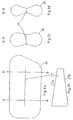
- the airbag according to Figures 1 to 3consists of a lower part 1 and an upper part 2, which are connected to one another by seams 3.
- the lower partis provided with an injection mouth 4 which is connected to a gas generator, not shown.
- a tether 5a, 5b or 5cextends across the airbag between the lower part and the upper part.
- the tetherruns in a straight line and has arcuate ends 6, 7.
- the tetheris connected on its long sides 8, 9 by seams 8a, 9a to the lower part or upper part.
- the sewing of the continuous tetheris easier than the sewing of several individual tethers lying next to each other between two adjacent chambers. Other types of fastening, such as gluing, are easier to implement.
- the tetherdivides the gas bag into two chambers 10, 11, which are connected to each other at both ends of the tether, since the tether does not extend to the edge of the gas bag. This subdivision ensures that the gas bag is first inflated in the region of the chamber 10 with the blowing mouth 4, and that it is inflated with a delay in the region of the chamber 11.
- the inflation of the gas bagcan be influenced by the size ratio of the chambers to one another.
- This size ratiocan be influenced by a different position of the tether shown in FIG. 1.
- the different angular position of the tether straps 5a, 5b and 5cnot only changes the size ratio of the chambers, but also changes the shape of each individual chamber.
- the tether 5ais arranged, the chamber 10 is larger in its right area than in the left area, while these areas are the same size with a tether 5b.
- the left area of the chamber 10is larger than the right area.
- the shape of the chamber 11changes accordingly in the opposite sense, i.e. enlarged areas of the chamber 10 are opposed to smaller areas of the chamber 11.
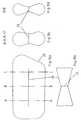
- FIG. 4A further possibility for influencing the size ratio of the chambers is shown in FIG. 4.
- a tether 12that is curved. It can thereby be achieved that the central area of the chambers has a different size than the lateral areas in the vicinity of the tether ends.
- FIG. 5shows an embodiment in which the tether divided the gas bag into three chambers.
- a V-shaped tether 13is provided, which divides the gas bag into three chambers 14, 15, 16.
- a zigzag tether 17, as shown in Fig. 6,can be used to further subdivide.
- four chambers 18 to 21are present.
- a gas bagcan be divided into different chambers with only one tether.
- FIG. 7shows how the airbag has to adapt to the constructive environment.
- a driver's seat 22, a door 23 and the B-pillar 24 of a motor vehiclecan be seen from the figure.
- an inflated gas bag 25can be seen, which extends out of the door. From the figure it can be seen that the airbag has a greater width in the door area than between the B-pillar and the seat.
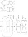
- an airbag 26is shown in which a tether 27 is provided.
- Thishas a trapezoidal shape, i.e. the side edges 27a and 27b run in different directions, as can be seen from FIG. 8b.
- the tetheris cut in this form.
- the gas bag in the unfolded statehas a greater width at interface A than at interface B, as can be seen from FIGS. 8c and 8d.
- an airbag 26 with a tether 28is provided, which has the shape of a double trapezoid.
- the two trapezoidshave the larger side 29 of the parallel sides as a common side. This makes the tether too narrow from the center towards its ends. Therefore, the gas bag in the unfolded state at interface B has a greater width than at interfaces A and C, as can be seen from FIGS. 9c and 9d.
- Figures 10a to 10dshow an embodiment in which the tether 30 also has the shape of a double trapezoid.
- the difference from the exemplary embodiment in FIGS. 9a to 9dis that the smaller side 31 of the parallel sides is provided as the common side. This makes the tether too wide from the center towards its ends.
- the airbagtherefore has a smaller width at interface B than at locations A and C, as can be seen from FIGS. 10c and 10d.
- FIGS. 11a to 11eThe further embodiment of the embodiment according to FIGS. 10a to 10d provides in FIGS. 11a to 11e that a double trapezoidal tether 32 has ends 33, 34 of different widths, so that the tether has differently shaped sections 35, 36. It is thereby achieved that the airbag has a different width at the interfaces A and C in the unfolded state, as can be seen from FIGS. 11c and 11e.
- FIGS. 12a to 12efinally show an exemplary embodiment with two tether straps 37, 38 which have different shapes.
- the tether 37corresponds to the tether 28 of FIG. 9b and the tether 38 to the tether 30 of FIG. 10b.
- the unfolded gas baghas a different course both in the middle and at the ends.
Landscapes
- Engineering & Computer Science (AREA)
- Mechanical Engineering (AREA)
- Air Bags (AREA)
Abstract
Description
Translated fromGermanDie Erfindung betrifft einen Gassack, insbesondere für ein Seitenairbagmodul, nach dem Oberbegriff des Anspruchs 1.The invention relates to an airbag, in particular for a side airbag module, according to the preamble of
Aus der DE 44 30 412 C1 ist eine Seitenaufprallschutzeinrichtung für einen Insassen eines Fahrzeuges mit einem mit einer Fülleinrichtung zusammenwirkenden aufblasbaren Gaskissen bekannt. Innerhalb des Gaskissens sind bei dieser Einrichtung Fangbänder vorgesehen, die das Gaskissen zumindest in zwei Kammern unterteilen, d.h. zwischen zwei Kammern sind mehrere nebeneinander liegende Fangbänder vorhanden. Zwischen zwei benachbarten Fangbändern sind entweder offene Spalte vorgesehen oder die Fangbänder sind durch Reißnähte miteinander verbunden. Diese reißen beim Füllen des Gassackes auf, so daß zwischen den benachbarten Fangbändern ebenfalls ein Spalt entsteht.From DE 44 30 412 C1 a side impact protection device for an occupant of a vehicle with an inflatable gas cushion interacting with a filling device is known. In this device, tether straps are provided within the gas cushion, which subdivide the gas cushion into at least two chambers, i.e. there are several adjacent tether straps between two chambers. Either open gaps are provided between two adjacent tether straps or the tether straps are connected to one another by tear seams. These tear open when the gas bag is filled, so that a gap is also formed between the adjacent tether straps.
Diese Art der Trennung zweier Kammern des Gassackes untereinander ist aufwendig, da zwischen beiden Kammern mehrere Fangbänder im Gassack zu befestigen sind.This type of separation of two chambers of the gas bag from one another is complex since a plurality of tether straps have to be fastened in the gas bag between the two chambers.
Aus der US 5 464 250 ist ein Airbag bekannt, bei dem ein Fangband zick-zack-förmig durch den Airbag verläuft. Dabei ist das Fangband abwechselnd an der Ober- und Unterseite des Airbags befestigt, so daß mehrere Kammern gebildet werden. Jeder Fangbandabschnitt weist Öffnungen auf, über die die Kammern miteinander verbunden sind. Weiterhin verlaufen die zwischen der Ober- und Unterseite zick-zack-förmig verlaufenden Seitenkanten des Fangbandes frei im Gassack.An airbag is known from US Pat. No. 5,464,250 in which a tether runs in a zigzag shape through the airbag. The tether is alternately attached to the top and bottom of the airbag, so that several chambers are formed. Each tether section has openings through which the chambers are connected to one another. Furthermore, the side edges of the tether running in a zigzag shape between the top and bottom run freely in the gas bag.
Diese Art der Anordnung eines Fangbandes weist den Nachteil auf, daß die Größe und Form der Kammern nur in begrenztem Umfang durch Änderung des Neigungswinkels der Fangbandabschnitte zwischen der Ober- und Unterseite des Airbags veränderbar sind.This type of arrangement of a tether has the disadvantage that the size and shape of the chambers are limited Scope can be changed by changing the angle of inclination of the tether portions between the top and bottom of the airbag.
Weiterhin ist aus der DE 44 43 027 A1 ein Gassack bekannt, der durch eine flexible Trennwand im Inneren des Gassackes in zwei Kammern aufgeteilt ist. Die Trennwand erstreckt sich über die gesamte Länge oder Breite und Tiefe des Gassackes und sie weist eine Öffnung für die Verbindung der beiden Kammern auf. Die Trennwand verläuft im aufgeblasenen Zustand geradlinig.Furthermore, a gas bag is known from DE 44 43 027 A1, which is divided into two chambers by a flexible partition inside the gas bag. The partition extends over the entire length or width and depth of the gas bag and it has an opening for connecting the two chambers. The partition is straight when inflated.
Bei beiden besteht der Nachteil, daß das Fangband zusätzliche Öffnungen für die Verbindung der Kammern aufweist.Both have the disadvantage that the tether has additional openings for connecting the chambers.
Der Erfindung liegt die Aufgabe zugrunde, einen Mehrkammer-Gassack zu schaffen, der einfacher herstellbar ist, und bei dem Kammern unterschiedlicher Form und Größe ebenfalls in einfacher Weise erzielbar sind.The invention has for its object to provide a multi-chamber gas bag that is easier to manufacture and in which chambers of different shapes and sizes can also be achieved in a simple manner.
Erfindungsgemäß wird das gemäß den Merkmalen des Anspruchs 1 erreicht.According to the invention this is achieved in accordance with the features of
Bei einem Gassack, insbesondere für ein Seitenairbagmodul, der mittels einer Fülleinrichtung aufblasbar ist und aus mindestens zwei miteinander verbundenen Kammern besteht, wobei zwischen jeweils zwei Kammern als Wand ein Fangband vorgesehen ist, das mit je einer der längeren Seitenkanten an gegenüberliegenden Flächen des Gassacks befestigt ist, ist erfindungsgemäß vorgesehen, daß die am Gassack befestigten Seitenkanten des Fangbandes im aufgeblasenen Zustand des Gassackes mindestens teilweise einen von der Geraden abweichenden Verlauf haben und/oder die gegenüberliegenden Seitenkanten in der Ebene des Fangbandes in unterschiedliche Richtungen verlaufen, und daß die schmalen Endkanten des Fangbandes im Abstand zum Gassack enden.In the case of a gas bag, in particular for a side airbag module, which is inflatable by means of a filling device and consists of at least two interconnected chambers, a tether being provided as a wall between each two chambers, which is attached to opposite surfaces of the gas bag with one of the longer side edges , It is provided according to the invention that the side edges of the tether attached to the gas bag in the inflated state of the airbag have at least partially a course deviating from the straight line and / or the opposite side edges run in different directions in the plane of the tether, and that the narrow end edges of the tether end at a distance from the airbag.
Durch diesen Verlauf der Seitenkanten des Fangbandes läßt sich der Gassack in einfacher Weise in Kammern unterschiedlicher Größe und Form unterteilen und weiterhin ist dadurch die Form des aufgeblasenen Gassacks beeinflußbar. Weiterhin wurde überraschend gefunden, daß zwischen benachbarten Kammern keine Öffnungen im Fangband oder nicht mehrere Fangbänder vorhanden sein müssen, zwischen denen beim Aufblasen des Gassackes Spalte vorhanden sind, um zwar ein verzögertes aber doch schnelles Füllen der zweiten Kammer zu ermöglichen. Vielmehr ist ein zufriedenstellendes Füllen der zweiten Kammer auch bei Anordnung nur eines Fangbandes als Kammerwand möglich, das nur an den schmalen Endkanten umströmt werden kann. Ein Fangband läßt sich zwischen zwei Kammern leichter im Gassack befestigen als mehrere Fangbänder, die zueinander ausgerichtet werden müssen.Through this course of the side edges of the tether, the gas bag can be easily divided into chambers of different sizes and shapes, and the shape of the inflated gas bag can also be influenced. Furthermore, it was surprisingly found that no openings in the tether or not a plurality of tethers must be present between adjacent chambers, between which there are gaps when the gas bag is inflated, in order to enable a delayed but rapid filling of the second chamber. Rather, a satisfactory filling of the second chamber is possible even when only one tether is arranged as the chamber wall, which can only be flowed around at the narrow end edges. A tether is easier to attach in the gas bag between two chambers than several tether that must be aligned with each other.
Durch die Änderung des Abstandes zwischen den Fangbandenden und dem Gasssackrand und damit des Querschnitts der Verbindungsöffnungen zwischen den Kammern kann die gewünschte Verzögerungszeit mit der die zweite Kammer gegenüber einer ersten Kammer aufgeblasen wird, die an eine Fülleinrichtung angeschlossen ist, beeinflußt werden.By changing the distance between the tether ends and the airbag edge and thus the cross-section of the connecting openings between the chambers, the desired delay time with which the second chamber is inflated compared to a first chamber, which is connected to a filling device, can be influenced.
Es ist zweckmäßig, daß das Fangband an seinen schmalen Enden bogenförmig verläuft, um eine erhöhte Stabilität der Enden zu erzielen und um die Form der Kammer zu beeinflussen. Weiterhin sollten die längeren Seitenkanten des Fangbandes durchgehend am Gassack befestigt sein.It is expedient for the tether to have an arcuate shape at its narrow ends in order to achieve increased stability of the ends and to influence the shape of the chamber. Furthermore, the longer side edges of the tether should be permanently attached to the gas bag.
In einer Ausführungform verläuft das Fangband in Längsrichtung des Kraftfahrzeuges und unterteilt den Gassack in zwei Kammern, von denen die erste an die Fülleinrichtung angeschlossen ist und das Fangband verläuft an seinen schmalen Enden in Richtung der zweiten Kammer bogenförmig.In one embodiment, the tether extends in the longitudinal direction of the motor vehicle and divides the gas bag into two chambers, the first of which is connected to the filling device and the tether has an arcuate shape at its narrow ends in the direction of the second chamber.
Eine Beeinflussung der Form und Größe benachbarter Kammern ist auch dadurch möglich, daß die am Gassack befestigten längeren Seitenkanten des Fangbandes insgesamt kurvenförmig verlaufen.Influencing the shape and size of adjacent chambers is also possible in that the longer side edges of the tether attached to the airbag are curved overall.
Bei Anordnung von mehr als zwei Kammern können für deren Unterteilung ein Fangband oder mehrere Fangbänder vorgesehen sein. Die Verwendung mehrerer Fangbänder für die Unterteilung unterschiedlicher Kammern ist nicht vergleichbar mit der Anordnung mehrerer Fangbänder zwischen zwei Kammern in dem oben genannten bekannten Gassack. Vielmehr ist auch in diesem Fall zwischen zwei benachbarten Kammern jeweils nur ein Fangband vorgesehen.If more than two chambers are arranged, a tether or several tethers can be provided for their division. The use of several tether straps for dividing different chambers is not comparable to the arrangement of several tether straps between two chambers in the known gas bag mentioned above. Rather, in this case only one tether is provided between two adjacent chambers.
Zur Bildung von mehr als zwei Kammern ist in einer Ausführungsform vorgesehen, daß die am Gassack befestigten längeren Seitenkanten des Fangbandes V-förmig verlaufen. In diesem Fall werden im Gassack drei Kammern gebildet, die nacheinander aufgeblasen werden. Eine noch weitergehende Unterteilung des Gassackes ist durch einen zickzackförmigen Verlauf der am Gassack befestigten längeren Seitenkanten des Fangbandes möglich.To form more than two chambers is provided in one embodiment that the longer side edges of the tether attached to the gas bag extend in a V-shape. In this case, three chambers are formed in the gas bag, which are inflated one after the other. A further subdivision of the airbag is possible due to the zigzag shape of the longer side edges of the tether attached to the airbag.
Eine Beeinflussung der Form des aufgeblasenen Gassackes ist auch dadurch möglich, daß die Seitenkanten des Fangbandes in unterschiedliche Richtungen verlaufen. Während bei einem parallelen Verlauf der Seitenkanten auch die angrenzenden Seiten des Gassackes nach dessen Entfaltung parallel verlaufen, ist das insbesondere bei Seitenairbags nicht immer zweckmäßig. Besonders dort ist der Gassack an das konstruktive Umfeld anzupassen, z.B. an den Raum zwischen dem Sitz und der B-Säule.Influencing the shape of the inflated gas bag is also possible in that the side edges of the tether run in different directions. While the side edges of the airbag also run parallel after the side edges have unfolded, this is not always expedient, particularly in the case of side airbags. Especially there the gas bag has to be adapted to the constructive environment, e.g. to the space between the seat and the B-pillar.
So ist in einer Ausführungform vorgesehen, daß das Fangband trapezförmig ist. Dadurch wird erreicht, daß der Gassack im entfalteten Zustand eine unterschiedliche Dicke aufweist, die sich zwischen den Enden des Fangbandes kontinuierlich verändert und dem verfügbaren Raum anpaßbar ist.It is provided in one embodiment that the tether is trapezoidal. It is thereby achieved that the airbag has a different thickness in the unfolded state, which changes continuously between the ends of the tether and can be adapted to the available space.
In einer weiteren Ausgestaltung dieser Ausführungsform ist vorgesehen, daß das Fangband die Form eines Doppeltrapezes aufweist, wobei beide Trapeze eine der parallelen Seiten als gemeinsame Seite haben. In dieser Ausführungsform nimmt die Dicke des entfalteten Gassackes von der gemeinsamen Seite aus zu den Enden des Fangbandes kontinuierlich zu oder ab, je nachdem ob das Doppeltrapez in der Mitte breiter oder schmaler als an den Enden ist.In a further embodiment of this embodiment it is provided that the tether has the shape of a double trapezoid, both trapezoids having one of the parallel sides as a common side. In this embodiment, the thickness of the unfolded airbag increases or decreases continuously from the common side to the ends of the tether, depending on whether the double trapezoid is wider or narrower in the middle than at the ends.
In einer anderen Ausführungsform ist vorgesehen, daß das Fangband Abschnitte unterschiedlicher Form aufweist und/oder die Fangbänder im Bereich unterschiedlicher Kammern unterschiedliche Formen aufweisen. Damit ist es möglich, den Gassack im aufgeblasenen Zustand noch besser an die unterschiedlichsten Raumverhältnisse anzupassen.In another embodiment it is provided that the tether has sections of different shape and / or the tether has different shapes in the area of different chambers. This makes it possible to adapt the gas bag even better to the most diverse spatial conditions when inflated.
In einer bevorzugten Ausführungsform besteht der Gassack aus einem plattenförmigen Unter- und Oberteil, zwischen denen sich das Fangband erstreckt bzw. die Fangbänder erstrecken und an denen sie befestigt sind.In a preferred embodiment, the gas bag consists of a plate-shaped lower and upper part, between which the tether extends or the tether extends and to which they are attached.
Die Erfindung soll in Ausführungsbeispielen anhand von Zeichnungen erläutert werden. Es zeigen:
- Fig. 1
- eine Ansicht auf die Unterseite eines ausgebreiteten Gassackes, teilweise geschnitten;
- Fig. 2
- einen Schnitt gemäß der Linie II - II der Fig. 1:
- Fig. 3
- einen Schnitt gemäß der Linie III - III der Fig. 1;
- Fig. 4 - 6
- Ansichten der Unterseite eines ausgebreiteten Gassackes mit unterschiedlich verlaufendem Fangband, teilweise geschnitten;
- Fig. 7
- die Draufsicht auf einen Fahrersitz mit entfaltetem Gassack;
- Fig. 8a
- einen Längsschnitt durch einen ausgebreitetem Gassack mit trapezförmigem Fangband;
- Fig. 8b
- eine Seitenansicht des Fangbandes nach Fig. 8a;
- Fig. 8c, d
- Querschnitte gemäß den Buchstaben A und B der Fig. 8a;
- Fig. 9a
- einen Längsschnitt durch einen ausgebreiteten Gassack mit einem Fangband, das die Form eines Doppeltrapezes mit der längeren der parallelen Seiten als gemeinsame Seite aufweist;
- Fig. 9b
- eine Seitenansicht des Fangbandes nach Fig. 9a;
- Fig. 9c, d
- Querschnitte gemäß den Buchstaben A, B und C der Fig. 9a;
- Fig. 10a
- einen Längsschnitt durch einen ausgebreiteten Gassack mit einem Fangband, das die Form eines Doppeltrapezes mit der kürzeren der parallelen Seiten als gemeinsame Seite aufweist;
- Fig. 10b
- eine Seitenansicht des Fangbandes nach Fig. 10a;
- Fig. 10c, d
- Querschnitte gemäß den Buchstaben A, B und C der Fig. 10a;
- Fig. 11a - e
- eine abgewandelte Ausführungsform der Figuren 10a - d, wobei die Trapeze eine unterschiedliche Form aufweisen;
- Fig. 12a
- einen Längssschnitt durch einen ausgebreiteten Gassack mit zwei Fangbändern unterschiedlicher Form;
- Fig. 12b, c
- Seitenansichten der Fangbänder nach Fig. 12a;
- Fig. 12d, e
- Querschnitte gemäß den Buchstaben A, B und C der Fig. 12a.
- Fig. 1
- a view of the underside of an expanded gas bag, partially cut;
- Fig. 2
- 2 shows a section along the line II-II of FIG. 1:
- Fig. 3
- a section along the line III - III of Fig. 1;
- 4 - 6
- Views of the underside of a spread out airbag with a differently extending tether, partially cut;
- Fig. 7
- the top view of a driver's seat with the gas bag unfolded;
- Fig. 8a
- a longitudinal section through an expanded gas bag with a trapezoidal tether;
- Fig. 8b
- a side view of the tether according to Fig. 8a;
- Fig. 8c, d
- Cross sections according to the letters A and B of Fig. 8a;
- Fig. 9a
- a longitudinal section through a spread out airbag with a tether that has the shape of a double trapezoid with the longer of the parallel sides as a common side;
- Fig. 9b
- a side view of the tether according to Fig. 9a;
- Fig. 9c, d
- Cross sections according to the letters A, B and C of Fig. 9a;
- Fig. 10a
- a longitudinal section through a spread out airbag with a tether that has the shape of a double trapezoid with the shorter of the parallel sides as a common side;
- Fig. 10b
- a side view of the tether according to Fig. 10a;
- Fig. 10c, d
- Cross sections according to the letters A, B and C of Fig. 10a;
- 11a-e
- a modified embodiment of Figures 10a-d, wherein the trapezoids have a different shape;
- Fig. 12a
- a longitudinal section through an airbag with two tethers of different shape;
- Fig. 12b, c
- Side views of the tether according to Fig. 12a;
- Fig. 12d, e
- Cross sections according to the letters A, B and C of Fig. 12a.
Der Gassack nach den Figuren 1 bis 3 besteht aus einem Unterteil 1 und einem Oberteil 2, die am Rand durch Nähte 3 miteinander verbunden sind. Das Unterteil ist mit einem Einblasmund 4 versehen, der an einen nicht dargestellten Gasgenerator angeschlossen wird. Zwischen dem Unterteil und dem Oberteil erstreckt sich quer durch den Gassack ein Fangband 5a, 5b oder 5c. Das Fangband verläuft geradlinig und weist bogenförmige Enden 6, 7 auf. Das Fangband ist an seinen Längsseiten 8, 9 durch Nähte 8a, 9a mit dem Unterteil bzw. Oberteil verbunden. Das Annähen des durchgehenden Fangbandes ist einfacher, als das Annähen mehrerer nebeneinander liegender einzelner Fangbänder zwischen zwei benachbarten Kammern. Auch andere Befestigungsarten, wie z.B. Kleben sind einfacher realisierbar.The airbag according to Figures 1 to 3 consists of a
Das Fangband teilt den Gassack in zwei Kammern 10, 11, die an beiden Enden des Fangbandes miteinander verbunden sind, da sich das Fangband nicht bis an den Rand des Gassackes erstreckt. Durch diese Unterteilung wird erreicht, daß der Gassack im Bereich der Kammer 10 mit dem Einblasmund 4 zuerst aufgeblasen wird, und daß er im Bereich der Kammer 11 verzögert aufgeblasen wird.The tether divides the gas bag into two
Das Aufblasen des Gassackes kann durch das Größenverhältnis der Kammern zueinander beeinflußt werden. Dieses Größenverhältnis kann durch eine in der Fig. 1 dargestellte unterschiedliche Lage des Fangbandes beeeinlußt werden. Durch die dargestellte unterschiedliche Winkellage der Fangbänder 5a, 5b und 5c wird nicht nur das Größenverhältnis der Kammern verändert, sondern jede einzelne Kammer wird auch in ihrer Form verändert. So ist die Kammer 10 bei Anordnung des Fangbandes 5a in ihrem rechten Bereich größer als im linken Bereich, während diese Bereiche mit einem Fangband 5b gleich groß sind. Mit einem Fangband 5c ist dagegen der linke Bereich der Kammer 10 größer als der rechte Bereich. Die Form der Kammer 11 verändert sich entsprechend im entgegengesetzten Sinn, d.h., vergrößerten Bereichen der Kammer 10 stehen verkleinerte Bereiche der Kammer 11 gegenüber.The inflation of the gas bag can be influenced by the size ratio of the chambers to one another. This size ratio can be influenced by a different position of the tether shown in FIG. 1. The different angular position of the tether straps 5a, 5b and 5c not only changes the size ratio of the chambers, but also changes the shape of each individual chamber. Thus, when the
Eine weitere Möglichkeit zur Beeinflussung des Größenverhältnisses der Kammern ist in der Fig. 4 dargestellt. Dort ist ein Fangband 12 vorgesehen, daß kurvenförmig verläuft. Dadurch kann erreicht werden, daß der mittlere Bereich der Kammern eine andere Größe aufweist als die seitlichen Bereiche in der Nähe der Fangbandenden.A further possibility for influencing the size ratio of the chambers is shown in FIG. 4. There is a
Während bei den bisher dargestellten Ausführungsformen der Gassack durch das Fangband in zwei Kammern unterteilt wurde, ist in der Fig. 5 eine Ausführungsform dargestellt, bei der das Fangband den Gassack in drei Kammern unterteilt. Hierzu ist ein V-förmig verlaufendes Fangband 13 vorgesehen, das den Gassack in drei Kammern 14, 15, 16 unterteilt. Durch die Dreiteilung des Gassackes ist eine feinere Abstufung des verzögerten Aufblasens bestimmter Bereiche des Gassackes zu erzielen.While in the previously illustrated embodiments the gas bag was divided into two chambers by the tether, FIG. 5 shows an embodiment in which the tether divided the gas bag into three chambers. For this purpose, a V-shaped
Durch ein zickzackförmig verlaufendes Fangband 17, wie es in Fig. 6 dargestellt ist, kann eine noch weitergehende Unterteilung erfolgen. In der dargestellten Ausführungsform sind vier Kammern 18 bis 21 vorhanden.A
Aus den Ausführungsbeispielen ist ersichtlich, daß mit nur einem Fangband eine Unterteilung eines Gassackes in verschiedene Kammern möglich ist.It can be seen from the exemplary embodiments that a gas bag can be divided into different chambers with only one tether.
Aus der Fig.7 ist am Beispiel eines Gassacks für einen Fahrersitz erkennbar, wie sich der Gassack an das konstuktive Umfeld anpassen muß. Aus der Figur sind ein Fahrersitz 22, eine Tür 23 und die B-Säule 24 eines Kraftfahrzeuges erkennbar. Weiterhin ist ein aufgeblasener Gassack 25 erkennbar, der sich aus der Tür heraus erstreckt. Aus der Figur ist ersichtlich, daß der Gassack im Türbereich eine größere Breite aufweist als zwischen der B-Säule und dem Sitz. Diese und andere Formen des Gassackes sind mit den als Trennwände vorgesehenen Fangbändern der nachfolgenden Ausführungsbeispiele erzielbar.Using the example of an airbag for a driver's seat, FIG. 7 shows how the airbag has to adapt to the constructive environment. A driver's
Im Ausführungsbeipiel der Figuren 8a bis d ist ein Gassack 26 dargestellt, in dem ein Fangband 27 vorgesehen ist. Dieses weist eine Trapezform auf, d.h., die Seitenkanten 27a und 27b verlaufen in unterschiedlichen Richtungen, wie es aus Fig. 8b ersichtlich ist. In dieser Form wird das Fangband zugeschnitten. Infolge dieses Verlaufs des Fangbandes weist der Gassack im entfalteten Zustand an der Schnittstelle A eine größere Breite auf als an der Schnittstelle B, wie es aus den Figuren 8c und 8d erkennbar ist.In the exemplary embodiment of FIGS. 8a to d, an
Im Ausführungsbeispiel der Figuren 9a bis d ist ein Gassack 26 mit einem Fangband 28 vorgesehen, das die Form eines Doppeltrapezes aufweist. Die beiden Trapeze weisen als gemeinsame Seite die größere Seite 29 der parallelen Seiten auf. Dadurch wird das Fangband von der Mitte aus nach seinen Enden zu schmaler. Deshalb weist der Gassack im entfalteten Zustand an der Schnittstelle B eine größere Breite auf als an den Schnittstellen A und C, wie es aus den Figuren 9c und 9d ersichtlich ist.In the exemplary embodiment in FIGS. 9a to d, an
Die Figuren 10a bis 10d zeigen ein Ausführungsbeispiel, bei dem das Fangband 30 ebenfalls die Form eines Doppeltrapezes aufweist. Der Unterschied zum Ausführungsbeispiel der Figuren 9a bis 9d besteht darin, daß die kleinere Seite 31 der parallelen Seiten als gemeinsame Seite vorgesehen ist. Dadurch wird das Fangband von der Mitte aus nach seinen Enden zu breiter. Der Gassack weist deshalb im entfalteten Zustand an der Schnittstelle B eine geringere Breite auf als an den Stellen A und C, wie es aus den Figuren 10c und 10d hervorgeht.Figures 10a to 10d show an embodiment in which the
Die weitere Ausgestaltung des Ausführungsbeispiels nach den Figuren 10a bis 10d sieht in den Figuren 11a bis 11e vor, daß ein doppeltrapezförmiges Fangband 32 unterschiedlich breite Enden 33, 34 aufweist, so daß das Fangband unterschiedlich geformte Abschnitte 35, 36 hat. Dadurch wird erreicht, daß der Gassack im entfalteten Zustand an den Schnittstellen A und C eine unterschiedliche Breite aufweist, wie es aus den Figuren 11c und 11e ersichtlich ist.The further embodiment of the embodiment according to FIGS. 10a to 10d provides in FIGS. 11a to 11e that a double
In den Figuren 12a bis 12e ist schließlich ein Ausführungsbeispiel mit zwei Fangbändern 37, 38 dargestellt, die unterschiedliche Formen aufweisen. Dabei entspricht das Fangband 37 dem Fangband 28 der Fig. 9b und das Fangband 38 dem Fangband 30 der Fig. 10b. Wie aus den Figuren 12d und 12e ersichtlich ist, weist der entfaltete Gassack sowohl in der Mitte als auch an den Enden einen unterschiedlichen Verlauf auf.FIGS. 12a to 12e finally show an exemplary embodiment with two
Die dargestellten Ausführungsformen zeigen beispielhaft die Möglichkeiten zur Beeinflussung der Gassackgeometrie durch die erfindungsgemäßen Fangbänder. Es ist erkennbar, daß beliebige andere Formen der Fangbänder möglich sind.The embodiments shown show an example of the possibilities for influencing the gas bag geometry by the tether straps according to the invention. It can be seen that any other forms of tether are possible.
Claims (12)
Translated fromGermandadurch gekennzeichnet,
daß die am Gassack (1) befestigten Seitenkanten (8, 9; 27a, 27b) des Fangbandes (5a, b, c) im aufgeblasenen Zustand des Gassackes mindestens teilweise einen von der Geraden abweichenden Verlauf haben und/oder in unterschiedliche Richtungen verlaufen, und daß die schmalen Enden (6, 7) des Fangbandes im Abstand zum Gassack verlaufen.Airbag, in particular for a side airbag module, which can be inflated by means of a filling device and consists of at least two interconnected chambers, a tether being provided as a wall between each two chambers, which is attached to opposite surfaces of the airbag with one of the longer side edges,
characterized by
that the side edges (8, 9; 27a, 27b) of the tether (5a, b, c) attached to the gas bag (1) have at least partially a course deviating from the straight line in the inflated state of the gas bag and / or run in different directions, and that the narrow ends (6, 7) of the tether run at a distance from the gas bag.
Priority Applications (3)
| Application Number | Priority Date | Filing Date | Title |
|---|---|---|---|
| JP9088505AJP3016746B2 (en) | 1996-04-24 | 1997-04-07 | Gas bag |
| US08/847,384US6032977A (en) | 1996-04-24 | 1997-04-23 | Gas bag |
| BR9701910ABR9701910A (en) | 1996-04-24 | 1997-04-23 | Gas bag especially for a side airbag module |
Applications Claiming Priority (2)
| Application Number | Priority Date | Filing Date | Title |
|---|---|---|---|
| DE29608055U | 1996-04-24 | ||
| DE29608055UDE29608055U1 (en) | 1996-04-24 | 1996-04-24 | Airbag, in particular for a side airbag module |
Publications (2)
| Publication Number | Publication Date |
|---|---|
| EP0803411A1true EP0803411A1 (en) | 1997-10-29 |
| EP0803411B1 EP0803411B1 (en) | 2001-05-16 |
Family
ID=8023505
Family Applications (1)
| Application Number | Title | Priority Date | Filing Date |
|---|---|---|---|
| EP97250024AExpired - LifetimeEP0803411B1 (en) | 1996-04-24 | 1997-02-04 | Air bag,in particular for a side air bag module |
Country Status (2)
| Country | Link |
|---|---|
| EP (1) | EP0803411B1 (en) |
| DE (2) | DE29608055U1 (en) |
Cited By (1)
| Publication number | Priority date | Publication date | Assignee | Title |
|---|---|---|---|---|
| US6540258B1 (en) | 1997-11-26 | 2003-04-01 | Takata-Petri Ag | Device for influencing the deployment of a gas bag in an airbag module |
Families Citing this family (7)
| Publication number | Priority date | Publication date | Assignee | Title |
|---|---|---|---|---|
| DE19652019A1 (en)* | 1996-12-13 | 1998-06-18 | Takata Europ Gmbh | Airbag for a side airbag |
| DE29705133U1 (en) | 1997-03-20 | 1997-07-24 | Trw Repa Gmbh | Airbag for a vehicle occupant protection system |
| DE19720586C2 (en)* | 1997-05-16 | 2000-11-30 | Porsche Ag | Side impact protection device for an occupant of a vehicle |
| DE19720587A1 (en)* | 1997-05-16 | 1998-11-19 | Porsche Ag | Side impact protection device for an occupant of a vehicle |
| DE19720584C2 (en) | 1997-05-16 | 2000-11-23 | Porsche Ag | Side impact protection device for an occupant of a vehicle |
| DE19720585A1 (en)* | 1997-05-16 | 1998-11-19 | Porsche Ag | Side impact protection device for an occupant of a vehicle |
| DE102004031865B4 (en)* | 2004-07-01 | 2009-01-15 | Autoliv Development Ab | Side airbag module for a vehicle seat of a motor vehicle |
Citations (9)
| Publication number | Priority date | Publication date | Assignee | Title |
|---|---|---|---|---|
| FR2227979A1 (en)* | 1973-05-02 | 1974-11-29 | Chrysler Corp | |
| US5160164A (en)* | 1991-06-05 | 1992-11-03 | Trw Vehicle Safety Systems Inc. | Gas deflection device for an air bag assembly |
| EP0600598A1 (en)* | 1992-12-01 | 1994-06-08 | Morton International, Inc. | Air bag cushion with fabric diffuser |
| DE4430412C1 (en) | 1994-08-26 | 1995-10-12 | Porsche Ag | Side impact protection system for occupant of vehicle |
| US5464250A (en) | 1992-06-17 | 1995-11-07 | Kabushiki Kaisha Tokai-Rika-Denki-Seisakusho | Bag suitable for use in an air bag apparatus and method of manufacturing the same |
| JPH07329667A (en)* | 1994-06-13 | 1995-12-19 | Takata Kk | Air bag for vehicle |
| DE29517372U1 (en)* | 1995-11-02 | 1996-02-01 | Trw Repa Gmbh | Airbag side impact protection device |
| DE4443027A1 (en) | 1994-12-02 | 1996-06-05 | Trw Repa Gmbh | Side impact gas bag |
| US5586782A (en)* | 1995-06-26 | 1996-12-24 | Alliedsignal Inc. | Dual pressure side impact air bag |
Family Cites Families (6)
| Publication number | Priority date | Publication date | Assignee | Title |
|---|---|---|---|---|
| US3788665A (en)* | 1971-05-12 | 1974-01-29 | Gen Motors Corp | Occupant restraint system |
| US4944527A (en)* | 1989-08-31 | 1990-07-31 | Allied-Signal Inc. | Integral retainer, heat shield and assembly |
| JPH03281460A (en)* | 1990-03-29 | 1991-12-12 | Mazda Motor Corp | Air bag device for automobile |
| GB2252083A (en)* | 1991-01-22 | 1992-07-29 | Dowty Woodville Polymer Ltd | Heat resistant vehicle crash bag. |
| JP3168591B2 (en)* | 1991-03-12 | 2001-05-21 | トヨタ自動車株式会社 | Airbag device |
| DE29518651U1 (en)* | 1995-11-24 | 1996-02-22 | Trw Repa Gmbh | Double chamber gas bag for a vehicle occupant restraint system |
- 1996
- 1996-04-24DEDE29608055Upatent/DE29608055U1/ennot_activeExpired - Lifetime
- 1997
- 1997-02-04EPEP97250024Apatent/EP0803411B1/ennot_activeExpired - Lifetime
- 1997-02-04DEDE59703533Tpatent/DE59703533D1/ennot_activeExpired - Lifetime
Patent Citations (10)
| Publication number | Priority date | Publication date | Assignee | Title |
|---|---|---|---|---|
| FR2227979A1 (en)* | 1973-05-02 | 1974-11-29 | Chrysler Corp | |
| US5160164A (en)* | 1991-06-05 | 1992-11-03 | Trw Vehicle Safety Systems Inc. | Gas deflection device for an air bag assembly |
| US5464250A (en) | 1992-06-17 | 1995-11-07 | Kabushiki Kaisha Tokai-Rika-Denki-Seisakusho | Bag suitable for use in an air bag apparatus and method of manufacturing the same |
| EP0600598A1 (en)* | 1992-12-01 | 1994-06-08 | Morton International, Inc. | Air bag cushion with fabric diffuser |
| JPH07329667A (en)* | 1994-06-13 | 1995-12-19 | Takata Kk | Air bag for vehicle |
| US5593179A (en)* | 1994-06-13 | 1997-01-14 | Takata Corporation | Air bag device for vehicle |
| DE4430412C1 (en) | 1994-08-26 | 1995-10-12 | Porsche Ag | Side impact protection system for occupant of vehicle |
| DE4443027A1 (en) | 1994-12-02 | 1996-06-05 | Trw Repa Gmbh | Side impact gas bag |
| US5586782A (en)* | 1995-06-26 | 1996-12-24 | Alliedsignal Inc. | Dual pressure side impact air bag |
| DE29517372U1 (en)* | 1995-11-02 | 1996-02-01 | Trw Repa Gmbh | Airbag side impact protection device |
Cited By (1)
| Publication number | Priority date | Publication date | Assignee | Title |
|---|---|---|---|---|
| US6540258B1 (en) | 1997-11-26 | 2003-04-01 | Takata-Petri Ag | Device for influencing the deployment of a gas bag in an airbag module |
Also Published As
| Publication number | Publication date |
|---|---|
| DE59703533D1 (en) | 2001-06-21 |
| EP0803411B1 (en) | 2001-05-16 |
| DE29608055U1 (en) | 1996-07-18 |
Similar Documents
| Publication | Publication Date | Title |
|---|---|---|
| DE19816061B4 (en) | Airbag assembly | |
| EP0773144B1 (en) | Air bag for a vehicle occupant restraint system | |
| DE69904985T2 (en) | Airbag for the head protection of vehicle occupants | |
| DE102006056603B4 (en) | The vehicle occupant restraint system | |
| DE102019124091A1 (en) | Airbag assembly for a vehicle occupant restraint system | |
| DE69803370T2 (en) | air bag | |
| EP0875426A2 (en) | Airbag curtain, in particular for a vehicle window | |
| WO2019197164A1 (en) | Airbag arrangement for a vehicle occupant restraint system | |
| DE4115884A1 (en) | COVER TO RECEIVE AN AIRBAG | |
| DE10063473B4 (en) | Roof railing for inflatable restraint system | |
| DE4040041C2 (en) | Holder for an airbag system | |
| EP4227168A1 (en) | AIRBAG FOR A DRIVERýS SEAT OF A VEHICLE AND AIRBAG MODULE, VEHICLE OCCUPANT SAFETY SYSTEM AND VEHICLE COMPRISING SUCH AN AIRBAG | |
| DE19823492A1 (en) | Side airbag | |
| EP0803411B1 (en) | Air bag,in particular for a side air bag module | |
| DE10251681A1 (en) | Side gas bag module for vehicle occupant protection system has elongated housing with first and second side parts brought together by back piece and with insides opposite to each other | |
| DE10126864B4 (en) | Knee protection device for vehicle occupants | |
| DE29804611U1 (en) | Airbag module, especially passenger airbag module | |
| DE10039555B4 (en) | Airbag and method for producing a gas bag | |
| WO2007028376A1 (en) | Airbag, in particular, for protecting the knee area of a vehicle occupant | |
| DE19519998C2 (en) | Passenger airbag module | |
| DE19505160C2 (en) | Rear bench seat for a station wagon | |
| DE102008030895B4 (en) | Arrangement for a vehicle seat | |
| DE20011327U1 (en) | Protective pillow for the head of a vehicle occupant, corresponding protective device and corresponding motor vehicle | |
| DE10159046B4 (en) | airbag mounting | |
| EP1359060B1 (en) | Airbag for a motor vehicle passenger restraining system |
Legal Events
| Date | Code | Title | Description |
|---|---|---|---|
| PUAI | Public reference made under article 153(3) epc to a published international application that has entered the european phase | Free format text:ORIGINAL CODE: 0009012 | |
| AK | Designated contracting states | Kind code of ref document:A1 Designated state(s):DE FR GB IT SE | |
| 17P | Request for examination filed | Effective date:19980128 | |
| RAP1 | Party data changed (applicant data changed or rights of an application transferred) | Owner name:DAIMLERCHRYSLER AG Owner name:PETRI AG | |
| 17Q | First examination report despatched | Effective date:19990721 | |
| GRAG | Despatch of communication of intention to grant | Free format text:ORIGINAL CODE: EPIDOS AGRA | |
| RIC1 | Information provided on ipc code assigned before grant | Free format text:7B 60R 21/16 A | |
| GRAG | Despatch of communication of intention to grant | Free format text:ORIGINAL CODE: EPIDOS AGRA | |
| GRAH | Despatch of communication of intention to grant a patent | Free format text:ORIGINAL CODE: EPIDOS IGRA | |
| GRAH | Despatch of communication of intention to grant a patent | Free format text:ORIGINAL CODE: EPIDOS IGRA | |
| GRAA | (expected) grant | Free format text:ORIGINAL CODE: 0009210 | |
| AK | Designated contracting states | Kind code of ref document:B1 Designated state(s):DE FR GB IT SE | |
| REF | Corresponds to: | Ref document number:59703533 Country of ref document:DE Date of ref document:20010621 | |
| ITF | It: translation for a ep patent filed | ||
| GBT | Gb: translation of ep patent filed (gb section 77(6)(a)/1977) | Effective date:20010817 | |
| RAP2 | Party data changed (patent owner data changed or rights of a patent transferred) | Owner name:DAIMLERCHRYSLER AG Owner name:TAKATA - PETRI AKTIENGESELLSCHAFT | |
| ET | Fr: translation filed | Owner name:DAIMLERCHRYSLER AG | |
| REG | Reference to a national code | Ref country code:GB Ref legal event code:IF02 | |
| PLBE | No opposition filed within time limit | Free format text:ORIGINAL CODE: 0009261 | |
| STAA | Information on the status of an ep patent application or granted ep patent | Free format text:STATUS: NO OPPOSITION FILED WITHIN TIME LIMIT | |
| 26N | No opposition filed | ||
| PGFP | Annual fee paid to national office [announced via postgrant information from national office to epo] | Ref country code:SE Payment date:20080219 Year of fee payment:12 Ref country code:IT Payment date:20080227 Year of fee payment:12 Ref country code:GB Payment date:20080130 Year of fee payment:12 | |
| PGFP | Annual fee paid to national office [announced via postgrant information from national office to epo] | Ref country code:FR Payment date:20080208 Year of fee payment:12 | |
| EUG | Se: european patent has lapsed | ||
| GBPC | Gb: european patent ceased through non-payment of renewal fee | Effective date:20090204 | |
| REG | Reference to a national code | Ref country code:FR Ref legal event code:ST Effective date:20091030 | |
| PG25 | Lapsed in a contracting state [announced via postgrant information from national office to epo] | Ref country code:GB Free format text:LAPSE BECAUSE OF NON-PAYMENT OF DUE FEES Effective date:20090204 Ref country code:FR Free format text:LAPSE BECAUSE OF NON-PAYMENT OF DUE FEES Effective date:20090302 | |
| PG25 | Lapsed in a contracting state [announced via postgrant information from national office to epo] | Ref country code:IT Free format text:LAPSE BECAUSE OF NON-PAYMENT OF DUE FEES Effective date:20090204 | |
| PG25 | Lapsed in a contracting state [announced via postgrant information from national office to epo] | Ref country code:SE Free format text:LAPSE BECAUSE OF NON-PAYMENT OF DUE FEES Effective date:20090205 | |
| PGFP | Annual fee paid to national office [announced via postgrant information from national office to epo] | Ref country code:DE Payment date:20120131 Year of fee payment:16 | |
| REG | Reference to a national code | Ref country code:DE Ref legal event code:R082 Ref document number:59703533 Country of ref document:DE Representative=s name:MAIKOWSKI & NINNEMANN PATENTANWAELTE, DE | |
| REG | Reference to a national code | Ref country code:DE Ref legal event code:R082 Ref document number:59703533 Country of ref document:DE Representative=s name:MAIKOWSKI & NINNEMANN PATENTANWAELTE, DE Effective date:20120904 Ref country code:DE Ref legal event code:R081 Ref document number:59703533 Country of ref document:DE Owner name:TAKATA AKTIENGESELLSCHAFT, DE Free format text:FORMER OWNERS: DAIMLER AG, 70327 STUTTGART, DE; TAKATA-PETRI AG, 63743 ASCHAFFENBURG, DE Effective date:20120904 Ref country code:DE Ref legal event code:R081 Ref document number:59703533 Country of ref document:DE Owner name:DAIMLER AG, DE Free format text:FORMER OWNERS: DAIMLER AG, 70327 STUTTGART, DE; TAKATA-PETRI AG, 63743 ASCHAFFENBURG, DE Effective date:20120904 Ref country code:DE Ref legal event code:R081 Ref document number:59703533 Country of ref document:DE Owner name:DAIMLER AG, DE Free format text:FORMER OWNER: DAIMLER AG, TAKATA-PETRI AG, , DE Effective date:20120904 Ref country code:DE Ref legal event code:R081 Ref document number:59703533 Country of ref document:DE Owner name:TAKATA AKTIENGESELLSCHAFT, DE Free format text:FORMER OWNER: DAIMLER AG, TAKATA-PETRI AG, , DE Effective date:20120904 | |
| REG | Reference to a national code | Ref country code:DE Ref legal event code:R119 Ref document number:59703533 Country of ref document:DE Effective date:20130903 | |
| PG25 | Lapsed in a contracting state [announced via postgrant information from national office to epo] | Ref country code:DE Free format text:LAPSE BECAUSE OF NON-PAYMENT OF DUE FEES Effective date:20130903 |