EP0801929B1 - Sleeve for rotary dental instrument - Google Patents
Sleeve for rotary dental instrumentDownload PDFInfo
- Publication number
- EP0801929B1 EP0801929B1EP97470003AEP97470003AEP0801929B1EP 0801929 B1EP0801929 B1EP 0801929B1EP 97470003 AEP97470003 AEP 97470003AEP 97470003 AEP97470003 AEP 97470003AEP 0801929 B1EP0801929 B1EP 0801929B1
- Authority
- EP
- European Patent Office
- Prior art keywords
- sleeve
- handle
- notched portion
- dental instrument
- cylindrical
- Prior art date
- Legal status (The legal status is an assumption and is not a legal conclusion. Google has not performed a legal analysis and makes no representation as to the accuracy of the status listed.)
- Expired - Lifetime
Links
- 229920003023plasticPolymers0.000claimsdescription14
- 239000004033plasticSubstances0.000claimsdescription14
- 239000000463materialSubstances0.000claimsdescription6
- 238000005304joiningMethods0.000claimsdescription2
- 229910052751metalInorganic materials0.000description5
- 239000002184metalSubstances0.000description5
- 238000004140cleaningMethods0.000description4
- 239000000645desinfectantSubstances0.000description3
- 238000004519manufacturing processMethods0.000description3
- 238000004659sterilization and disinfectionMethods0.000description3
- WSFSSNUMVMOOMR-UHFFFAOYSA-NFormaldehydeChemical compoundO=CWSFSSNUMVMOOMR-UHFFFAOYSA-N0.000description2
- PXHVJJICTQNCMI-UHFFFAOYSA-NNickelChemical compound[Ni]PXHVJJICTQNCMI-UHFFFAOYSA-N0.000description2
- 238000004873anchoringMethods0.000description2
- 229910001369BrassInorganic materials0.000description1
- 229910052782aluminiumInorganic materials0.000description1
- XAGFODPZIPBFFR-UHFFFAOYSA-NaluminiumChemical compound[Al]XAGFODPZIPBFFR-UHFFFAOYSA-N0.000description1
- 239000010951brassSubstances0.000description1
- 238000005553drillingMethods0.000description1
- 230000000694effectsEffects0.000description1
- 238000000465mouldingMethods0.000description1
- 229910052759nickelInorganic materials0.000description1
- MOFOBJHOKRNACT-UHFFFAOYSA-Nnickel silverChemical compound[Ni].[Ag]MOFOBJHOKRNACT-UHFFFAOYSA-N0.000description1
- 239000010956nickel silverSubstances0.000description1
- 230000003252repetitive effectEffects0.000description1
- 239000010935stainless steelSubstances0.000description1
- 229910001220stainless steelInorganic materials0.000description1
- 238000001356surgical procedureMethods0.000description1
- 230000008961swellingEffects0.000description1
Images
Classifications
- A—HUMAN NECESSITIES
- A61—MEDICAL OR VETERINARY SCIENCE; HYGIENE
- A61C—DENTISTRY; APPARATUS OR METHODS FOR ORAL OR DENTAL HYGIENE
- A61C3/00—Dental tools or instruments
- A61C3/02—Tooth drilling or cutting instruments; Instruments acting like a sandblast machine
- B—PERFORMING OPERATIONS; TRANSPORTING
- B25—HAND TOOLS; PORTABLE POWER-DRIVEN TOOLS; MANIPULATORS
- B25G—HANDLES FOR HAND IMPLEMENTS
- B25G3/00—Attaching handles to the implements
- B25G3/34—Attaching handles to the implements by pressing the handle on the implements; using cement or molten metal, e.g. casting, moulding, by welding or the like
- A—HUMAN NECESSITIES
- A61—MEDICAL OR VETERINARY SCIENCE; HYGIENE
- A61C—DENTISTRY; APPARATUS OR METHODS FOR ORAL OR DENTAL HYGIENE
- A61C5/00—Filling or capping teeth
- A61C5/40—Implements for surgical treatment of the roots or nerves of the teeth; Nerve needles; Methods or instruments for medication of the roots
- A61C5/42—Files for root canals; Handgrips or guiding means therefor
- Y—GENERAL TAGGING OF NEW TECHNOLOGICAL DEVELOPMENTS; GENERAL TAGGING OF CROSS-SECTIONAL TECHNOLOGIES SPANNING OVER SEVERAL SECTIONS OF THE IPC; TECHNICAL SUBJECTS COVERED BY FORMER USPC CROSS-REFERENCE ART COLLECTIONS [XRACs] AND DIGESTS
- Y10—TECHNICAL SUBJECTS COVERED BY FORMER USPC
- Y10T—TECHNICAL SUBJECTS COVERED BY FORMER US CLASSIFICATION
- Y10T408/00—Cutting by use of rotating axially moving tool
- Y10T408/89—Tool or Tool with support
- Y10T408/907—Tool or Tool with support including detailed shank
Definitions
- the present inventionrelates to handles for rotary instruments dental, particularly but not limited to, for treatment instruments Ductal.
- Instruments used in dental surgeryrequire hygiene perfect, which requires dental surgeons to regularly cleaning or disinfection of said instruments, which causes damage, in particular the aluminum handles can be attacked by disinfectants and the plastic sleeves swell under the effect of the formalin used also as a disinfectant.
- the handle as describedhas some disadvantages. Indeed, the anchoring means as provided in said patent are made by drilling a cylindrical metal sleeve or an overflow in plastic with respect to said cylindrical metallic sleeve.
- the object of the present inventionis to remedy the drawbacks of devices of the prior art as presented above.
- a handleis proposed for this purpose.
- dental instruments with rotary channelsconsisting of a metal sleeve cylindrical into which the non-active end of the instrument is introduced, the space between the sleeve and the rod being filled with a plastic material which constitutes a core joining the sleeve and the rod which protrudes at the end of the sleeve to form the instrument head, at least one anchorage being provided between the sleeve and plastic core characterized in that the anchoring is carried out thanks to at least one longitudinal notching produced on the internal wall of the sleeve cylindrical over at least part of its length, notch in which the plastic material, said notching not extending to the ends of the sleeve.
- the handle for a rotary dental instrumentessentially consists of a hollow cylindrical sleeve (1) of metal, for example nickel silver, brass nickel plated or stainless steel and inside this sleeve is molded a plastic core (2).
- the tool rod (3)which will have been inserted prior to molding in the sleeve (1) so that its axis is substantially in the axis of the sleeve, is embedded in the plastic core (2) and therefore connected rigidly to him and to the sleeve.
- the notch (s)are executed inside the wall of the sleeve so as not to protrude from the ends of the sleeve (4a) constituting an anchor.
- FIG. 3represents the notch (s) executed inside the wall of the sleeve so as to lead to one of the ends of the sleeve (4b).
- FIG. 4represents the notches executed inside the wall of the sleeve so as to lead to the two ends of the sleeve (4c).
- the notch (s)may have a tail shape dovetail (see Figure 5) or a V shape (see Figure 6).
Landscapes
- Health & Medical Sciences (AREA)
- Oral & Maxillofacial Surgery (AREA)
- Dentistry (AREA)
- Epidemiology (AREA)
- Life Sciences & Earth Sciences (AREA)
- Animal Behavior & Ethology (AREA)
- General Health & Medical Sciences (AREA)
- Public Health (AREA)
- Veterinary Medicine (AREA)
- Engineering & Computer Science (AREA)
- Mechanical Engineering (AREA)
- Dental Tools And Instruments Or Auxiliary Dental Instruments (AREA)
Description
Translated fromFrenchLa présente invention concerne les manches pour instruments rotatifsdentaires, particulièrement mais non limitativement, pour instruments de traitementcanalaire.The present invention relates to handles for rotary instrumentsdental, particularly but not limited to, for treatment instrumentsDuctal.
Les instruments utilisés dans la chirurgie dentaire nécessitent une hygièneparfaite, ce qui oblige les chirurgiens-dentistes à procéder régulièrement aunettoyage ou à la désinfection desdits instruments, ce qui engendre des dommages,en particulier les manches en aluminium peuvent être attaqués par les désinfectantset les manches en matière plastique gonflent sous l'effet du formol employéégalement comme désinfectant.Instruments used in dental surgery require hygieneperfect, which requires dental surgeons to regularlycleaning or disinfection of said instruments, which causes damage,in particular the aluminum handles can be attacked by disinfectantsand the plastic sleeves swell under the effect of the formalin usedalso as a disinfectant.
On a déjà proposé pour remédier à ces inconvénients un manche mixte àsavoir qu'il n'est pas uniquement en matière plastique permettant audit manched'être moins sensible à un nettoyage ou à une désinfection. Un tel manche a étédécrit dans le brevet français FR-A-2 499 446.A mixed handle has already been proposed to remedy these drawbacks.know that it is not only plastic allowing said sleeveto be less sensitive to cleaning or disinfection. Such a round wasdescribed in French patent FR-A-2 499 446.
Même s'il donne satisfaction, le manche tel que décrit présente quelquesinconvénients. En effet, les moyens d'ancrage tels que prévus dans ledit brevet sontréalisés par un perçage d'un manchon métallique cylindrique ou un débordement enplastique par rapport audit manchon métallique cylindrique.Even if it gives satisfaction, the handle as described has somedisadvantages. Indeed, the anchoring means as provided in said patent aremade by drilling a cylindrical metal sleeve or an overflow inplastic with respect to said cylindrical metallic sleeve.
Ceci a pour inconvénient que lorsque l'utilisateur traite pour le nettoyageet/ou la désinfection les instruments à canaux avec des produits provoquant ungonflement du plastique, le plastique "sort" légèrement du manchon métalliquecylindrique et fait saillie, ce qui peut rendre difficile la mise en place de l'instrumentdans la pièce à main.This has the disadvantage that when the user is processing for cleaningand / or disinfection of channel instruments with products causingswelling of the plastic, the plastic "comes out" slightly from the metal sleevecylindrical and protruding, which can make it difficult to set up the instrumentin the handpiece.
De plus, certains de ces modes de réalisation d'instruments dentairesrequièrent une reprise du manchon métallique cylindrique pour sa fabrication, ce quirend plus onéreuse ladite fabrication.In addition, some of these embodiments of dental instrumentsrequire a rework of the cylindrical metal sleeve for its manufacture, whichmakes said manufacturing more expensive.
La présente invention a pour but de remédier aux inconvénients desdispositifs de l'art antérieur tels que présentés ci-dessus.The object of the present invention is to remedy the drawbacks ofdevices of the prior art as presented above.
Conformément à l'invention, on propose à cette fin un manche pourinstruments dentaires à canaux rotatifs constitué par un manchon métalliquecylindrique dans lequel est introduite l'extrémité non active de l'instrument, l'espacecompris entre le manchon et la tige étant rempli par une matière plastique quiconstitue un noyau solidarisant le manchon et la tige qui dépasse à l'extrémité dumanchon pour former la tête d'instrument, au moins un ancrage étant prévu entre lemanchon et le noyau en matière plastique caractérisé en ce que l'ancrage est réaliségrâce à au moins un crantage longitudinal réalisé sur la paroi interne du manchoncylindrique sur au moins une partie de sa longueur, crantage dans lequel se loge lamatière plastique, ledit crantage ne s'étendant pas jusqu'aux extrémitésdu manchon.In accordance with the invention, a handle is proposed for this purpose.dental instruments with rotary channels consisting of a metal sleevecylindrical into which the non-active end of the instrument is introduced, the spacebetween the sleeve and the rod being filled with a plastic material whichconstitutes a core joining the sleeve and the rod which protrudes at the end of thesleeve to form the instrument head, at least one anchorage being provided between thesleeve and plastic core characterized in that the anchoring is carried outthanks to at least one longitudinal notching produced on the internal wall of the sleevecylindrical over at least part of its length, notch in which theplastic material, said notching not extending to the endsof the sleeve.
On comprendra mieux l'invention à l'aide de la description faite ci-aprèsd'un mode préférentiel de mise en oeuvre, donné à titre d'exemple non limitatif, enréférence aux dessins annexés dans lesquels :
- lafigure 1 est une vue en élévation et en coupe partielle du manche,
- lesfigures 2 à 4 sont des vues de profil des manchons correspondant àtrois variantes d'exécution,
- lafigure 5 représente une vue en coupe partielle du dessin du manche,
- lafigure 6 représente une vue en coupe partielle d'une varianted'exécution illustrant un crantage en forme de V.
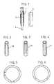
- FIG. 1 is a view in elevation and in partial section of the handle,
- FIGS. 2 to 4 are side views of the sleeves corresponding to three variant embodiments,
- FIG. 5 represents a partial section view of the drawing of the handle,
- Figure 6 shows a partial sectional view of an alternative embodiment illustrating a V-shaped notch.
On se réfère tout d'abord à la figure 1.We first refer to Figure 1.
Le manche pour instrument dentaire rotatif se compose essentiellement d'unmanchon cylindrique creux (1) en métal, par exemple en maillechort, en laitonnickelé ou en acier inoxydable et à l'intérieur de ce manchon se trouve moulé unnoyau en matière plastique (2).The handle for a rotary dental instrument essentially consists of ahollow cylindrical sleeve (1) of metal, for example nickel silver, brassnickel plated or stainless steel and inside this sleeve is molded aplastic core (2).
La tige de l'outil (3) qui aura été insérée préalablement au moulage dans lemanchon (1) de telle manière que son axe soit sensiblement dans l'axe du manchon, se trouve noyée dans le noyau de matière plastique (2) et donc reliéerigidement à lui et au manchon.The tool rod (3) which will have been inserted prior to molding in thesleeve (1) so that its axis is substantially in the axis of thesleeve, is embedded in the plastic core (2) and therefore connectedrigidly to him and to the sleeve.
En référence aux figures 2, 3 et 4, on a représenté différentes formesd'exécution du manchon.Referring to Figures 2, 3 and 4, different shapes have been shownof the sleeve.
Sur la figure 2, le ou les crantages sont exécutés à l'intérieur de la paroi dumanchon de telle manière à ne pas dépasser des extrémités du manchon (4a)constituant un ancrage.In FIG. 2, the notch (s) are executed inside the wall of thesleeve so as not to protrude from the ends of the sleeve (4a)constituting an anchor.
Dans une variante d'exécution non conforme à l'invention, la figure 3 représente le ou les crantagesexécutés à l'intérieur de la paroi du manchon de telle manière à déboucher à l'unedes extrémités du manchon (4b).In an alternative embodiment not in accordance with the invention, FIG. 3 represents the notch (s)executed inside the wall of the sleeve so as to lead to oneof the ends of the sleeve (4b).
Dans une autre variante d'exécution non conforme à l'invention, la figure 4 représente le ou lescrantages exécutés à l'intérieur de la paroi du manchon de façon à déboucher auxdeux extrémités du manchon (4c).In another alternative embodiment not in accordance with the invention, FIG. 4 represents thenotches executed inside the wall of the sleeve so as to lead to thetwo ends of the sleeve (4c).
Avantageusement, le ou les crantages pourront avoir une forme en queued'aronde (voir figure 5) ou une forme en V (voir figure 6).Advantageously, the notch (s) may have a tail shapedovetail (see Figure 5) or a V shape (see Figure 6).
C'est dans ce ou ces dits crantages que viendront se loger la matièreplastique conférant au manche une moindre fragilité et une meilleure résistance auxdésinfectants nécessaires aux nettoyages répétitifs des instruments dentaires.It is in this or these so-called notches that will be housed the materialplastic giving the handle less fragility and better resistance todisinfectants necessary for repetitive cleaning of dental instruments.
Les différents éléments du manche tels que décrits seront réalisés par desprocédés de fabrication qu'il n'est pas nécessaire de décrire ici.The various elements of the handle as described will be produced bymanufacturing processes which need not be described here.
Claims (3)
- Handle for a rotary grooved dental instrument, said handle beingformed by a cylindrical metallic sleeve (1), into which is introduced thenon-active end of the instrument, the space between the sleeve (1) andthe shaft (3) being filled by a plastics material (2), which forms a corejoining together the sleeve and the shaft, and which protrudes beyond theend of the sleeve to form the head of the instrument, at least oneanchorage being provided between the cylindrical sleeve and the coreformed from plastics material,characterised in that the anchorage isproduced by means of at least one longitudinal notched portion (4)provided on the internal wall of the cylindrical sleeve over at least somepart of its length, in which notched portion is housed the plasticsmaterial, said notched portion not extending as far as the ends of thesleeve.
- Handle for a rotary grooved dental instrument according to claim1,characterised in that the notched portion or portions has or have adovetail-shaped configuration.
- Handle for a rotary grooved dental instrument according to claim1,characterised in that the notched portion or portions has or have a V-shapedconfiguration.
Applications Claiming Priority (2)
| Application Number | Priority Date | Filing Date | Title |
|---|---|---|---|
| FR9604988AFR2747563B1 (en) | 1996-04-17 | 1996-04-17 | HANDLE FOR ROTARY DENTAL INSTRUMENT |
| FR9604988 | 1996-04-17 |
Publications (2)
| Publication Number | Publication Date |
|---|---|
| EP0801929A1 EP0801929A1 (en) | 1997-10-22 |
| EP0801929B1true EP0801929B1 (en) | 2002-07-10 |
Family
ID=9491416
Family Applications (1)
| Application Number | Title | Priority Date | Filing Date |
|---|---|---|---|
| EP97470003AExpired - LifetimeEP0801929B1 (en) | 1996-04-17 | 1997-02-07 | Sleeve for rotary dental instrument |
Country Status (5)
| Country | Link |
|---|---|
| US (1) | US5897318A (en) |
| EP (1) | EP0801929B1 (en) |
| JP (1) | JPH1033560A (en) |
| DE (1) | DE69713831T2 (en) |
| FR (1) | FR2747563B1 (en) |
Families Citing this family (10)
| Publication number | Priority date | Publication date | Assignee | Title |
|---|---|---|---|---|
| GB9930554D0 (en)* | 1999-12-23 | 2000-02-16 | Fiskars Uk Ltd | The manufacture of implements |
| FR2855962B1 (en)* | 2003-06-12 | 2005-08-19 | Micro Mega Int Mfg Sa | MECHANIZED DENTAL INSTRUMENT. |
| DE602004015243D1 (en)* | 2004-03-29 | 2008-09-04 | Maillefer Instr Holding S A R | Disposable dental instrument |
| EP1609560B1 (en)* | 2004-06-21 | 2009-05-20 | Straumann Holding AG | Method for manufacturing disposable rotary cutting tools and disposable rotary tool for dental or medical applications |
| US20070141532A1 (en)* | 2005-12-20 | 2007-06-21 | Ford Christopher W | Force distributing dental implant assembly |
| US7682152B2 (en) | 2005-12-20 | 2010-03-23 | Ford Christopher W | Force distributing dental implant assembly |
| US20070141533A1 (en)* | 2005-12-20 | 2007-06-21 | Ford Christopher W | Polymeric dental implant assembly |
| KR100959639B1 (en)* | 2007-04-05 | 2010-05-26 | 이인환 | Needle Unit of Root Canal Therapy |
| US8011926B2 (en) | 2008-05-15 | 2011-09-06 | Ford Christopher W | Polymeric dental implant assembly |
| DE102010002557A1 (en)* | 2010-03-03 | 2011-09-08 | Sandvik Intellectual Property Ab | Cutting tool with backlash-free fine adjustment |
Family Cites Families (8)
| Publication number | Priority date | Publication date | Assignee | Title |
|---|---|---|---|---|
| US628927A (en)* | 1898-08-20 | 1899-07-18 | Francis Ducharme | Tool-handle. |
| US2606366A (en)* | 1948-10-13 | 1952-08-12 | James B Stevens | Vibration dampening and insulating means for tools such as dental tools |
| US2871899A (en)* | 1958-04-16 | 1959-02-03 | Bridgeport Hardware Mfg Corp | Tool handles |
| DE1126560B (en)* | 1960-06-04 | 1962-03-29 | Finzler Schrock & Kimmel | Dental instrument |
| US4321040A (en)* | 1980-12-09 | 1982-03-23 | Ipco Corporation | Endodontic instrument |
| AU552062B2 (en)* | 1981-01-06 | 1986-05-22 | Stuart Julian Filhol | Dental anchoring means |
| FR2499446A1 (en)* | 1981-02-12 | 1982-08-13 | Micro Mega Sa | HANDLE FOR ROTARY CHANNEL DENTAL INSTRUMENT, AND METHOD FOR MANUFACTURING SUCH HANDLE |
| CH669513A5 (en)* | 1986-07-07 | 1989-03-31 | Maillefer Auguste Sa |
- 1996
- 1996-04-17FRFR9604988Apatent/FR2747563B1/ennot_activeExpired - Fee Related
- 1997
- 1997-02-07EPEP97470003Apatent/EP0801929B1/ennot_activeExpired - Lifetime
- 1997-02-07DEDE69713831Tpatent/DE69713831T2/ennot_activeExpired - Fee Related
- 1997-04-16USUS08/840,742patent/US5897318A/ennot_activeExpired - Fee Related
- 1997-04-17JPJP9114220Apatent/JPH1033560A/enactivePending
Also Published As
| Publication number | Publication date |
|---|---|
| JPH1033560A (en) | 1998-02-10 |
| EP0801929A1 (en) | 1997-10-22 |
| DE69713831D1 (en) | 2002-08-14 |
| FR2747563B1 (en) | 1998-06-05 |
| FR2747563A1 (en) | 1997-10-24 |
| DE69713831T2 (en) | 2003-03-27 |
| US5897318A (en) | 1999-04-27 |
Similar Documents
| Publication | Publication Date | Title |
|---|---|---|
| EP0801929B1 (en) | Sleeve for rotary dental instrument | |
| EP2023840B1 (en) | Dynamometric tool for medical use | |
| FR2680461A1 (en) | IMPLANT FOR OSTEOSYNTHESIS DEVICE, ESPECIALLY OF THE RACHIS, AND CORRESPONDING DEVICE FOR ITS PLACEMENT. | |
| FR2621465A1 (en) | INTERDENTAL BRUSH | |
| CH644049A5 (en) | HANDLE FOR USE IN CONNECTION WITH A TOOL IN THE FORM OF '' L ''. | |
| FR2516416A1 (en) | POWER TOOL HAVING A PLASTIC HOUSING | |
| FR2642283A1 (en) | Artist's brush including a protective case for the tuft of bristles | |
| FR2681223A1 (en) | Device for aiding walking, of the crutch or English walking stick (cane) type | |
| FR2465469A1 (en) | INSTRUMENT FOR THE TREATMENT OF DENTAL CHANNELS | |
| EP0909870A1 (en) | Coupling for a force transmitting device | |
| CH646045A5 (en) | HANDLE FOR A ROTARY CHANNEL DENTAL INSTRUMENT, AND METHOD FOR MANUFACTURING SUCH A HANDLE | |
| EP0880943A1 (en) | Screwdriver for a screw with two threaded parts separated by an intermediate tightening section | |
| FR2465468A1 (en) | DENTAL TOOL AND ITS TOOL HOLDER | |
| WO2014140448A1 (en) | Rotatable and/or vibrating surgical instrument suitable for dispensing a fluid | |
| CA2520294C (en) | Device for cleaning inter-dental spaces | |
| EP0283377B1 (en) | Bushing for connecting a cylindrical or oval handle to a conical bore of a tool | |
| CH628799A5 (en) | DEVICE FOR FIXING A DENTAL INSTRUMENT IN A HANDPIECE. | |
| BE1014828A6 (en) | Potato hollowing out tool comprises long rod with inclined end serving as handle and helicoidal screw attached to rest of rod guiding movement on potato and ring attached to rod at screw end has cutting edge | |
| FR2834630A1 (en) | Cotyloid cup for head of artificial hip joint femoral implant is made from two hemispherical shells, one partly flexible and other rigid | |
| WO2008129217A2 (en) | Root canal instrument handle made of two co-axial portions joined in axial translation and in rotation | |
| FR2530225A1 (en) | DEVICE FOR PROTECTING THE THREAD REALIZED AT THE END OF A TUBULAR PIECE | |
| FR2671025A1 (en) | SELF-LOCKING NUT HOLDER FOR PRESENTATION. | |
| FR2763231A1 (en) | Tool to open oyster with spiral on rod | |
| FR2613930A1 (en) | Gutta-percha applicator for obturation of tooth canals | |
| FR2837367A1 (en) | Disposable toothbrush has hollow handle with flexible walls which is filled with toothpaste dispensed through channel with outlet in head |
Legal Events
| Date | Code | Title | Description |
|---|---|---|---|
| PUAI | Public reference made under article 153(3) epc to a published international application that has entered the european phase | Free format text:ORIGINAL CODE: 0009012 | |
| AK | Designated contracting states | Kind code of ref document:A1 Designated state(s):CH DE ES GB IT LI SE | |
| 17P | Request for examination filed | Effective date:19980310 | |
| 17Q | First examination report despatched | Effective date:20000705 | |
| GRAG | Despatch of communication of intention to grant | Free format text:ORIGINAL CODE: EPIDOS AGRA | |
| GRAG | Despatch of communication of intention to grant | Free format text:ORIGINAL CODE: EPIDOS AGRA | |
| GRAH | Despatch of communication of intention to grant a patent | Free format text:ORIGINAL CODE: EPIDOS IGRA | |
| GRAH | Despatch of communication of intention to grant a patent | Free format text:ORIGINAL CODE: EPIDOS IGRA | |
| GRAA | (expected) grant | Free format text:ORIGINAL CODE: 0009210 | |
| AK | Designated contracting states | Kind code of ref document:B1 Designated state(s):CH DE ES GB IT LI SE | |
| PG25 | Lapsed in a contracting state [announced via postgrant information from national office to epo] | Ref country code:IT Free format text:LAPSE BECAUSE OF FAILURE TO SUBMIT A TRANSLATION OF THE DESCRIPTION OR TO PAY THE FEE WITHIN THE PRE;WARNING: LAPSES OF ITALIAN PATENTS WITH EFFECTIVE DATE BEFORE 2007 MAY HAVE OCCURRED AT ANY TIME BEFORE 2007. THE CORRECT EFFECTIVE DATE MAY BE DIFFERENT FROM THE ONE RECORDED.SCRIBED TIME-LIMIT Effective date:20020710 Ref country code:GB Free format text:LAPSE BECAUSE OF FAILURE TO SUBMIT A TRANSLATION OF THE DESCRIPTION OR TO PAY THE FEE WITHIN THE PRESCRIBED TIME-LIMIT Effective date:20020710 | |
| REG | Reference to a national code | Ref country code:GB Ref legal event code:FG4D Free format text:NOT ENGLISH | |
| REG | Reference to a national code | Ref country code:CH Ref legal event code:EP | |
| REF | Corresponds to: | Ref document number:69713831 Country of ref document:DE Date of ref document:20020814 | |
| REG | Reference to a national code | Ref country code:CH Ref legal event code:NV Representative=s name:SPIERENBURG HELMLE-KOLB & PARTNER AG PATENT- UND M | |
| PG25 | Lapsed in a contracting state [announced via postgrant information from national office to epo] | Ref country code:SE Free format text:LAPSE BECAUSE OF FAILURE TO SUBMIT A TRANSLATION OF THE DESCRIPTION OR TO PAY THE FEE WITHIN THE PRESCRIBED TIME-LIMIT Effective date:20021010 | |
| GBV | Gb: ep patent (uk) treated as always having been void in accordance with gb section 77(7)/1977 [no translation filed] | Effective date:20020710 | |
| PG25 | Lapsed in a contracting state [announced via postgrant information from national office to epo] | Ref country code:ES Free format text:LAPSE BECAUSE OF FAILURE TO SUBMIT A TRANSLATION OF THE DESCRIPTION OR TO PAY THE FEE WITHIN THE PRESCRIBED TIME-LIMIT Effective date:20030130 | |
| PG25 | Lapsed in a contracting state [announced via postgrant information from national office to epo] | Ref country code:LI Free format text:LAPSE BECAUSE OF NON-PAYMENT OF DUE FEES Effective date:20030228 Ref country code:CH Free format text:LAPSE BECAUSE OF NON-PAYMENT OF DUE FEES Effective date:20030228 | |
| PLBE | No opposition filed within time limit | Free format text:ORIGINAL CODE: 0009261 | |
| STAA | Information on the status of an ep patent application or granted ep patent | Free format text:STATUS: NO OPPOSITION FILED WITHIN TIME LIMIT | |
| 26N | No opposition filed | Effective date:20030411 | |
| PG25 | Lapsed in a contracting state [announced via postgrant information from national office to epo] | Ref country code:DE Free format text:LAPSE BECAUSE OF NON-PAYMENT OF DUE FEES Effective date:20030902 | |
| REG | Reference to a national code | Ref country code:CH Ref legal event code:PL |