EP0801629B1 - Apparatus and method for removing articles from a stack - Google Patents
Apparatus and method for removing articles from a stackDownload PDFInfo
- Publication number
- EP0801629B1 EP0801629B1EP96900148AEP96900148AEP0801629B1EP 0801629 B1EP0801629 B1EP 0801629B1EP 96900148 AEP96900148 AEP 96900148AEP 96900148 AEP96900148 AEP 96900148AEP 0801629 B1EP0801629 B1EP 0801629B1
- Authority
- EP
- European Patent Office
- Prior art keywords
- stack
- conveying means
- articles
- planar
- article
- Prior art date
- Legal status (The legal status is an assumption and is not a legal conclusion. Google has not performed a legal analysis and makes no representation as to the accuracy of the status listed.)
- Expired - Lifetime
Links
- 238000000034methodMethods0.000titleclaimsdescription11
- 230000001360synchronised effectEffects0.000claimsdescription4
- 235000015895biscuitsNutrition0.000description50
- 238000004519manufacturing processMethods0.000description4
- 239000004677NylonSubstances0.000description1
- 238000013459approachMethods0.000description1
- 238000005336crackingMethods0.000description1
- 229920001778nylonPolymers0.000description1
Images


Classifications
- B—PERFORMING OPERATIONS; TRANSPORTING
- B65—CONVEYING; PACKING; STORING; HANDLING THIN OR FILAMENTARY MATERIAL
- B65G—TRANSPORT OR STORAGE DEVICES, e.g. CONVEYORS FOR LOADING OR TIPPING, SHOP CONVEYOR SYSTEMS OR PNEUMATIC TUBE CONVEYORS
- B65G59/00—De-stacking of articles
- B65G59/06—De-stacking from the bottom of the stack
- B65G59/067—De-stacking from the bottom of the stack articles being separated substantially perpendicularly to the axis of the stack
- B65G59/068—De-stacking from the bottom of the stack articles being separated substantially perpendicularly to the axis of the stack by means of endless elements
Definitions
- the present inventionrelates to apparatus and a method for removing articles from a stack, and is concerned particularly, although not exclusively, with apparatus and a method for removing delicate or friable articles, such as biscuits, from a stack.
- the present inventionprovides a much smoother conveying path, particularly suitable for transporting biscuits.
- apparatus for removing planar articles from a stackcomprises conveying means and a number of projections located on the conveying means, each projection comprising a leading edge which is substantially transverse to the extent of the conveying means and a trailing edge which tapers towards the conveying means; said conveying means being adapted to be located in use substantially below a stack of articles in stack retaining means, characterised in that the portion of the conveying means directly below the stack of articles is angled downwardly with respect to the stack of articles; that in use the conveying means is arranged to convey a lowermost article in the stack downwardly with respect to the stack retaining means, and the stack of articles descends at a constant speed relative to the speed of the conveying means.
- the downward motion of the stackis continuous.
- the arrangementis such that in use the stack of articles maintains a downward motion with respect to the stack retaining means.
- the conveying meanscomprises an endless belt or track, which may be driven by a pulley.
- the portion of the conveying means directly below the stackis arranged to travel downwardly with respect to the stack in the direction of travel of the conveying means.
- Said portion of the conveying meansis preferably substantially flat.
- the angle between the said portion of the conveying means and the horizontal extent of the stackis preferably such that a lower most article of the stack is removed and travels downwardly with respect to the stack retaining means by a distance substantially equal to the thickness of an article.
- the trailing edge of the projectionis arranged, in use, to support the next lower most article in the stack.
- the articlesare preferably urged onto guide means arranged to guide the motion of the articles away from the stack.
- the urging meansmay comprise one or more pin members, which pin members may be driven by a chain and sprocket type drive.
- the guide meansmay comprise a number of wires arranged to support articles from below.
- the or each articlemay in use be inverted after removal from the stack, by co-operation of the articles with a retaining member, which retaining member extends partly around a pulley of the conveying means, and is spaced from the conveying means.
- the or each articleis supported by one or more support members which are fixed relative to the pulley, to support the or each article as it travels around the pulley.
- the support membersmay comprise projections fixed to the pulley.
- the fixed projectionsmay be attached to or integral with a plate mounted on the side of the pulley, such that the fixed projections extend radially outward with respect to the pulley.
- the pulleysmay each have a plate, such that the conveying means extend between the plates.
- the fixed projectionsare spaced apart by an extent substantially equal to the spacing of the articles on the conveying means.
- each conveying meanssupports the lower most article as it is removed from the stack, there being one conveying means located substantially either side of a centre of a lower most article.
- the motion of the two conveying meansis synchronised, such that in use projections on the two conveying means arrive at the lower most article at substantially the same time.
- a conveyor support meansarranged, in use, to support at least the portion of the conveying means directly below the stack, such that the said portion of the conveying means extends at an angle below horizontal.
- the conveyor support meansmay be adjustable such that the angle below the horizontal at which the said portion of the conveying means extends in use may be adjusted.
- the conveyor support meansis adjustable pivotally with respect to a pulley of the conveying means.
- the inventionalso includes a method of removing planar articles from a stack in a stack retaining means, the method comprising conveying the lowermost article of the stack away from the stack on conveying means, characterised in that the conveying means is arranged to convey the lowermost article in the stack downwardly with respect to the stack retaining means until the said article is conveyed beyond a horizontal extent of the stack and to descend the stack of articles at a constant speed relative to the speed of the conveying means.
- the vertical downward movement of the stackis continuous.
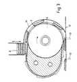
- a de-stacking unit shown generally at 1has a conveyor belt 2 on which are mounted projections 3.
- Each of the projections 3comprises a blade member having a leading edge 4 which is substantially normal to the surface of the belt 2, and a trailing support edge 5.
- the belt 2is driven by a pulley or wheel 6 and the belt 2 is arranged to extend around a nylon support 7 positioned to the side of the pulley 6.
- the supportcommonly referred to as a follower, is pivotally mounted about the centre of the drive pulley 6.
- the de-stacker unit 1is positioned below a substantially vertical stack of biscuits 8 held in a magazine 9.
- the position of the drive pulley 6is arranged such that clockwise rotation of the pulley 6 results in a left to right movement of the portion of the belt 2 beneath the magazine 9.
- the support 7is mounted relative to the pulley 6 such that the portion of the belt 2 directly below the stack 8 of biscuits is angled downwardly with respect to the stack 8.
- the profile of the support 7is such that the portion of the belt 2 directly below the stack 8 of biscuits is substantially flat.
- the downward speed of the stackis determined by the angle of the belt below horizontal for any given belt speed.
- various sizes and thicknesses of biscuitcan be accommodated by varying the spacing between the projections on the belt and both the angle and speed of the belt.
- the range of biscuits that can be accommodated by one beltwill primarily be determined by the height of the leading edge of the projections which must be no greater than the thickness of the biscuit and is preferably substantially the same as the thickness of the biscuit.
- FIG. 3shows an alternative embodiment of apparatus to remove articles from a stack in which the biscuits are inverted after removal from the stack, i.e. to present the underside of the biscuits in the stack as the upperside for the next stage in a production process.
- an arcuate retaining member 14is provided adjacent to the surface of the belt 2 which follows the belt 2 around the drive pulley 6 in order to retain the biscuits on the surface of the belt 2 as they travel around the pulley 6.
- the inverted biscuitsare then presented to guide wires 12 below the pulley 6 and are urged along by contact with driven pins 13.
- a further embodiment of apparatus for removing articles from a stackincludes the addition of a circular plate 15 mounted on the side of pulley 6.
- the plate 15has fixed radially extending pins 16, the spacing of which is substantially equal to the spacing of the biscuits on the belt. As the biscuits travel around the pulley between the belt 2 and the retaining member 14, the biscuits are prevented from falling forwards and potentially jamming or breaking by the pins 16.
- Angular adjustment of the plate 15 on the pulley 6may be achieved using a conventional slot and screw arrangement shown generally at 17. If a single pulley is used there is preferably a plate 15 mounted on each side of the pulley. If two pulleys are used there is preferably a plate 15 mounted on the outer surface of each of the two pulleys, with the belts extending between the plates 15.
- the stack as a wholemaintains a constant downward motion which is not arrested at any time during the de-stacking process. Since the stack of biscuits is not undergoing a start-stop vibration there is less likelihood of damage to the biscuits.
- the projections 3are made sufficiently flexible to follow the path of the belt 2.
- An advantage of using a belt as the conveying meansis that the belt with its associated projections 3 can easily be changed when this is required to suit a different type of biscuit.
Landscapes
- Stacking Of Articles And Auxiliary Devices (AREA)
- Belt Conveyors (AREA)
Description
Claims (27)
- Apparatus (1) for removing planar articles from a stack (8), theapparatus comprising conveying means and a number of projections (3)located on the conveying means, each projection (3) comprising a leadingedge (4) which is substantially transverse to the extent of the conveyingmeans and a trailing edge (5) which tapers towards the conveying means;said conveying means being adapted to be located in use substantiallybelow a stack of articles (8) in stack retaining means (9), characterised inthat the portion of the conveying means directly below the stack of articles(8) is angled downwardly with respect to the stack of articles (8); that inuse the conveying means is arranged to convey a lowermost article (10) inthe stack (8) downwardly with respect to the stack retaining means (9), andthe stack of articles (8) descends at a constant speed relative to the speed ofthe conveying means.
- Apparatus (1) for removing planar articles from a stack (8)according to claim 1, characterised in that in use the downward motion ofthe stack (8) is continuous.
- Apparatus according to claim 1 or claim 2, characterised in that thestack of planar articles maintains a downward motion with respect to thestack retaining means (9).
- Apparatus according to any one of claims 1 to 3, characterised inthat the conveying means comprises an endless belt or track (2), which beltor track is driven by a pulley (6).
- Apparatus according to any of claims 1 to 4, characterised in that theportion of the conveying means (2) directly below the stack is arranged totravel downwardly with respect to the stack retaining means (9) in thedirection of travel of the conveying means.
- Apparatus according to claim 5, characterised in that said portion ofthe conveying means (2) is substantially flat.
- Apparatus according to claim 5 or claim 6, characterised in that theangle between the said portion of the conveying means and the horizontalextent of the stack is such that a lowermost planar article of the stack isremoved and travels downwardly with respect to the stack retaining means(9) by a distance substantially equal to the thickness of a planar article.
- Apparatus according to any of claims 1 to 7, characterised in that theor each projection comprises a blade member (3) having a leading edge (4)which is substantially transverse to the extent of the conveying means (2),and a trailing edge (5) which tapers towards the conveying means.
- Apparatus according to claim 8, characterised in that the heightabove the conveying means of the leading edge of the projection is notgreater than the thickness of a planar article.
- Apparatus according to claim 8 or claim 9, characterised in that thetrailing edge (5) of the projection (3) is arranged to support the nextlowermost planar article (11) in the stack.
- Apparatus according to any of claims 1 to 10, characterised in thatthe articles are urged on to guide means (12) arranged to guide the motionof the planar articles away from the stack.
- Apparatus according to claim 11, characterised in that there isprovided additional urging means (13) to urge the planar articles onto theguide means (12).
- Apparatus according to claim 12, characterised in that the urgingmeans comprise one or more pin members (13).
- Apparatus according to any of claims 11 to 13, characterised in thatthe guide means comprises a number of wires (12) arranged to supportplanar articles (10) from below.
- Apparatus according to any of claims 1 to 10, characterised in thatthe or each planar article is inverted after removal from the stack, by co-operationof the planar articles with a retaining member (14), whichretaining member extends partly around a pulley (6) of the conveyingmeans, and is spaced from the conveying means.
- Apparatus according to claim 15, characterised in that the or eachplanar article is supported by one or more support members (16) which arefixed relative to the pulley, to support the or each planar article as it travelsaround the pulley.
- Apparatus according to claim 16, characterised in that the supportmembers comprise projections (16) fixed to the pulley.
- Apparatus according to claim 17, characterised in that the fixedprojections (16) are attached to or integral with a plate (15) mounted on theside of the pulley, such that the fixed projections extend radially outwardwith respect to the pulley.
- Apparatus according to claim 18, characterised in that there areprovided two plates located either side of the pulley of the conveyingmeans.
- Apparatus according to claim 17, characterised in that the fixedprojections (16) are spaced apart by an extent substantially equal to thespacing of the planar articles on the conveying means (2).
- Apparatus according to any of claims 1 to 20, characterised in thattwo conveying means are provided below the stack of planar articles, suchthat each conveying means supports the lowermost planar article as it isremoved from the stack, there being one conveying means locatedsubstantially either side of a centre of a lowermost article.
- Apparatus according to claim 21, characterised in that the motion ofthe two conveying means is synchronised such that projections (16) on thetwo conveying means arrive at the lowermost article at substantially thesame time.
- Apparatus according to any of claims 1 to 22, characterised in thatthere is provided a conveyor support means (7) arranged to support at leastthe portion of the conveying means (2) directly below the stack such thatthe said portion of the conveying means extends at an angle belowhorizontal.
- Apparatus according to a claim 23, characterised in that theconveyor support means (7) is adjustable such that the angle below thehorizontal at which the said portion of the conveying means extends maybe adjusted.
- Apparatus according to claim 24, characterised in that the conveyorsupport means (7) is adjustable pivotally with respect to a pulley (6) of theconveying means.
- A method of removing planar articles (8) from a stack in a stackretaining means (9), the method comprising conveying the lowermostarticle (10) of the stack (8) away from the stack (8) on conveying means,characterised in that the conveying means is arranged to convey thelowermost article (10) in the stack (8) downwardly with respect to the stackretaining means (9) until the said article (10) is conveyed beyond ahorizontal extent of the stack (8) and to descend the stack of articles (8) ata constant speed relative to the speed of the conveying means.
- A method of removing planar articles (8) from a stack according toclaim 26 characterised in that in use the downward movement of the stack(8) is continuous.
Applications Claiming Priority (3)
| Application Number | Priority Date | Filing Date | Title |
|---|---|---|---|
| GB9500714AGB2296914B (en) | 1995-01-14 | 1995-01-14 | Apparatus and method for removing articles from a stack |
| GB9500714 | 1995-01-14 | ||
| PCT/GB1996/000056WO1996021612A1 (en) | 1995-01-14 | 1996-01-12 | Apparatus and method for removing articles from a stack |
Publications (2)
| Publication Number | Publication Date |
|---|---|
| EP0801629A1 EP0801629A1 (en) | 1997-10-22 |
| EP0801629B1true EP0801629B1 (en) | 2000-03-29 |
Family
ID=10768028
Family Applications (1)
| Application Number | Title | Priority Date | Filing Date |
|---|---|---|---|
| EP96900148AExpired - LifetimeEP0801629B1 (en) | 1995-01-14 | 1996-01-12 | Apparatus and method for removing articles from a stack |
Country Status (5)
| Country | Link |
|---|---|
| EP (1) | EP0801629B1 (en) |
| DE (1) | DE69607457D1 (en) |
| DK (1) | DK0801629T3 (en) |
| GB (1) | GB2296914B (en) |
| WO (1) | WO1996021612A1 (en) |
Families Citing this family (12)
| Publication number | Priority date | Publication date | Assignee | Title |
|---|---|---|---|---|
| WO2001005235A2 (en)* | 1999-07-16 | 2001-01-25 | Stuck Robert M | Loader for conveyorized cooking apparatus |
| DE102005012420A1 (en)* | 2005-03-11 | 2006-09-14 | Walter Hanke Mechanische Werkstätten GmbH & Co KG | Coin dispensing device, has drive intervening recess in base plate of coin tube for contacting and driving of bottom of coins that are stacked in coin tube, where drive enables moving out of coins through opening of coin tube |
| ITTO20060900A1 (en)* | 2006-12-19 | 2008-06-20 | Cavanna Spa | "PROCEDURE FOR THE EXTRACTION OF INDIVIDUAL PRODUCTS FROM A CONTINUOUS PLATE OF PRODUCTS" |
| ITTO20070083A1 (en)* | 2007-02-05 | 2008-08-06 | Cavanna Spa | "DEVICE TO FORM PRODUCT GROUPS" |
| US10173849B2 (en)* | 2017-02-01 | 2019-01-08 | Bosch Packaging Technology, Inc. | Method and system for extracting articles |
| DE102018009755B4 (en)* | 2018-12-12 | 2020-12-03 | Messer Group Gmbh | Device for loading a refrigerant storage compartment of a cooling container with dry ice |
| NL1043435B1 (en)* | 2019-10-21 | 2021-07-29 | Dero Groep Joure Bv | Device for destacking a sliced loaf of bread into individual slices. |
| CN111761865B (en)* | 2020-05-30 | 2021-12-17 | 浙江三阳包装产业股份有限公司 | Conveying equipment for corrugated paper processing |
| CN111731808A (en)* | 2020-06-28 | 2020-10-02 | 嘉兴卓尔精密机械有限公司 | Conveying device for processing metal plate |
| CN112173563B (en)* | 2020-10-10 | 2022-04-22 | 天长市祥瑞电子有限公司 | Charger upper cover shell automatic feeding device |
| WO2024196767A1 (en)* | 2023-03-17 | 2024-09-26 | Duke Manufacturing Co. | Food dispenser |
| CN118183151B (en)* | 2024-03-21 | 2025-09-16 | 益阳市明正宏电子有限公司 | A circuit board conveying device for automated production of circuit boards |
Family Cites Families (5)
| Publication number | Priority date | Publication date | Assignee | Title |
|---|---|---|---|---|
| GB393336A (en)* | ||||
| US2198036A (en)* | 1937-06-04 | 1940-04-23 | Isted Reginald Miles | Conveyer for tiles and the like |
| US2910211A (en)* | 1953-06-26 | 1959-10-27 | American Can Co | Feeding mechanism for fragile articles |
| CH650985A5 (en)* | 1981-05-12 | 1985-08-30 | Sig Schweiz Industrieges | METHOD FOR REMOVING AT LEAST ONE FLAT OBJECT FROM A STACK, AND APPLYING THE METHOD. |
| GB8805082D0 (en)* | 1988-03-03 | 1988-03-30 | Burton S Gold Medal Biscuits | Improvements in & relating to apparatus for use in removing generally planar articles from stack |
- 1995
- 1995-01-14GBGB9500714Apatent/GB2296914B/ennot_activeExpired - Fee Related
- 1996
- 1996-01-12EPEP96900148Apatent/EP0801629B1/ennot_activeExpired - Lifetime
- 1996-01-12DEDE69607457Tpatent/DE69607457D1/ennot_activeExpired - Lifetime
- 1996-01-12DKDK96900148Tpatent/DK0801629T3/enactive
- 1996-01-12WOPCT/GB1996/000056patent/WO1996021612A1/enactiveIP Right Grant
Also Published As
| Publication number | Publication date |
|---|---|
| WO1996021612A1 (en) | 1996-07-18 |
| GB2296914A (en) | 1996-07-17 |
| GB2296914B (en) | 1999-04-21 |
| EP0801629A1 (en) | 1997-10-22 |
| DE69607457D1 (en) | 2000-05-04 |
| GB9500714D0 (en) | 1995-03-08 |
| DK0801629T3 (en) | 2000-07-24 |
Similar Documents
| Publication | Publication Date | Title |
|---|---|---|
| EP0801629B1 (en) | Apparatus and method for removing articles from a stack | |
| KR100454349B1 (en) | Packing machine for multi-packs | |
| US5147027A (en) | Article group-segregating apparatus and method | |
| EP0819091B1 (en) | Apparatus and method for flipping and positioning articles | |
| US4519505A (en) | Egg transfer system | |
| US4164996A (en) | Tile stacking machine and method | |
| US5363950A (en) | Lumber organizer | |
| US5628614A (en) | Continuous motion stacking apparatus and methods | |
| US5020655A (en) | Article group-segregating apparatus and method | |
| EP0096505A1 (en) | Picking device | |
| EP0601221B1 (en) | Gripping device | |
| EP0665810B1 (en) | Continuous motion upender | |
| US3912070A (en) | Tray handling apparatus | |
| US5012916A (en) | Article group-segregating apparatus and method | |
| US4565443A (en) | Printing apparatus | |
| JP5052934B2 (en) | Sliced bread dividing and carrying device | |
| US4354590A (en) | Spacer escalator for spacing loads in carton loading machines | |
| EP1015357B1 (en) | Lifting device for lifting and/or lowering an ordered stack of articles | |
| US4629056A (en) | Yeast cake tumbler | |
| US4678456A (en) | Carton opening apparatus | |
| KR20230165121A (en) | Takeout apparatus for frozen foods | |
| JP3009362B2 (en) | Unstacker device and unstacker method | |
| US4995225A (en) | Compact food tray film wrapping machine | |
| JPH0754177Y2 (en) | Standing Article Separation Device | |
| EP0489478A1 (en) | Apparatus for placing articles on a conveyor |
Legal Events
| Date | Code | Title | Description |
|---|---|---|---|
| PUAI | Public reference made under article 153(3) epc to a published international application that has entered the european phase | Free format text:ORIGINAL CODE: 0009012 | |
| 17P | Request for examination filed | Effective date:19970717 | |
| AK | Designated contracting states | Kind code of ref document:A1 Designated state(s):BE DE DK ES FR IT NL SE | |
| 17Q | First examination report despatched | Effective date:19971111 | |
| GRAG | Despatch of communication of intention to grant | Free format text:ORIGINAL CODE: EPIDOS AGRA | |
| GRAG | Despatch of communication of intention to grant | Free format text:ORIGINAL CODE: EPIDOS AGRA | |
| GRAG | Despatch of communication of intention to grant | Free format text:ORIGINAL CODE: EPIDOS AGRA | |
| GRAH | Despatch of communication of intention to grant a patent | Free format text:ORIGINAL CODE: EPIDOS IGRA | |
| RAP1 | Party data changed (applicant data changed or rights of an application transferred) | Owner name:APV UK PLC | |
| RBV | Designated contracting states (corrected) | Designated state(s):BE DE DK ES FR IT NL SE | |
| RAP1 | Party data changed (applicant data changed or rights of an application transferred) | Owner name:APV UK LIMITED | |
| GRAH | Despatch of communication of intention to grant a patent | Free format text:ORIGINAL CODE: EPIDOS IGRA | |
| GRAA | (expected) grant | Free format text:ORIGINAL CODE: 0009210 | |
| AK | Designated contracting states | Kind code of ref document:B1 Designated state(s):BE DE DK ES FR IT NL SE | |
| PG25 | Lapsed in a contracting state [announced via postgrant information from national office to epo] | Ref country code:SE Free format text:THE PATENT HAS BEEN ANNULLED BY A DECISION OF A NATIONAL AUTHORITY Effective date:20000329 Ref country code:NL Free format text:LAPSE BECAUSE OF FAILURE TO SUBMIT A TRANSLATION OF THE DESCRIPTION OR TO PAY THE FEE WITHIN THE PRESCRIBED TIME-LIMIT Effective date:20000329 Ref country code:ES Free format text:THE PATENT HAS BEEN ANNULLED BY A DECISION OF A NATIONAL AUTHORITY Effective date:20000329 Ref country code:BE Free format text:LAPSE BECAUSE OF FAILURE TO SUBMIT A TRANSLATION OF THE DESCRIPTION OR TO PAY THE FEE WITHIN THE PRESCRIBED TIME-LIMIT Effective date:20000329 | |
| REF | Corresponds to: | Ref document number:69607457 Country of ref document:DE Date of ref document:20000504 | |
| ITF | It: translation for a ep patent filed | ||
| PG25 | Lapsed in a contracting state [announced via postgrant information from national office to epo] | Ref country code:DE Free format text:LAPSE BECAUSE OF FAILURE TO SUBMIT A TRANSLATION OF THE DESCRIPTION OR TO PAY THE FEE WITHIN THE PRESCRIBED TIME-LIMIT Effective date:20000630 | |
| ET | Fr: translation filed | ||
| REG | Reference to a national code | Ref country code:DK Ref legal event code:T3 | |
| NLV1 | Nl: lapsed or annulled due to failure to fulfill the requirements of art. 29p and 29m of the patents act | ||
| PLBE | No opposition filed within time limit | Free format text:ORIGINAL CODE: 0009261 | |
| STAA | Information on the status of an ep patent application or granted ep patent | Free format text:STATUS: NO OPPOSITION FILED WITHIN TIME LIMIT | |
| PGFP | Annual fee paid to national office [announced via postgrant information from national office to epo] | Ref country code:DK Payment date:20010131 Year of fee payment:6 | |
| 26N | No opposition filed | ||
| PG25 | Lapsed in a contracting state [announced via postgrant information from national office to epo] | Ref country code:DK Free format text:LAPSE BECAUSE OF NON-PAYMENT OF DUE FEES Effective date:20020112 | |
| PG25 | Lapsed in a contracting state [announced via postgrant information from national office to epo] | Ref country code:IT Free format text:LAPSE BECAUSE OF NON-PAYMENT OF DUE FEES;WARNING: LAPSES OF ITALIAN PATENTS WITH EFFECTIVE DATE BEFORE 2007 MAY HAVE OCCURRED AT ANY TIME BEFORE 2007. THE CORRECT EFFECTIVE DATE MAY BE DIFFERENT FROM THE ONE RECORDED. Effective date:20050112 | |
| PGFP | Annual fee paid to national office [announced via postgrant information from national office to epo] | Ref country code:FR Payment date:20051229 Year of fee payment:11 | |
| REG | Reference to a national code | Ref country code:FR Ref legal event code:ST Effective date:20070930 | |
| PG25 | Lapsed in a contracting state [announced via postgrant information from national office to epo] | Ref country code:FR Free format text:LAPSE BECAUSE OF NON-PAYMENT OF DUE FEES Effective date:20070131 |