EP0797962B1 - Areal implant - Google Patents
Areal implantDownload PDFInfo
- Publication number
- EP0797962B1 EP0797962B1EP97250072AEP97250072AEP0797962B1EP 0797962 B1EP0797962 B1EP 0797962B1EP 97250072 AEP97250072 AEP 97250072AEP 97250072 AEP97250072 AEP 97250072AEP 0797962 B1EP0797962 B1EP 0797962B1
- Authority
- EP
- European Patent Office
- Prior art keywords
- plunger
- basic structure
- implant according
- areal
- knitted fabric
- Prior art date
- Legal status (The legal status is an assumption and is not a legal conclusion. Google has not performed a legal analysis and makes no representation as to the accuracy of the status listed.)
- Expired - Lifetime
Links
- 239000007943implantSubstances0.000titleclaimsdescription97
- 239000000463materialSubstances0.000claimsdescription46
- 239000004744fabricSubstances0.000claimsdescription35
- 210000003815abdominal wallAnatomy0.000claimsdescription17
- -1polypropylenePolymers0.000claimsdescription15
- 239000004743PolypropyleneSubstances0.000claimsdescription14
- 238000010586diagramMethods0.000claimsdescription14
- 229920001155polypropylenePolymers0.000claimsdescription14
- 229920001577copolymerPolymers0.000claimsdescription11
- 239000011248coating agentSubstances0.000claimsdescription9
- 238000000576coating methodMethods0.000claimsdescription9
- 229920000728polyesterPolymers0.000claimsdescription7
- RKDVKSZUMVYZHH-UHFFFAOYSA-N1,4-dioxane-2,5-dioneChemical compoundO=C1COC(=O)CO1RKDVKSZUMVYZHH-UHFFFAOYSA-N0.000claimsdescription6
- 229920000117poly(dioxanone)Polymers0.000claimsdescription6
- JJTUDXZGHPGLLC-UHFFFAOYSA-NlactideChemical compoundCC1OC(=O)C(C)OC1=OJJTUDXZGHPGLLC-UHFFFAOYSA-N0.000claimsdescription5
- 230000007423decreaseEffects0.000claimsdescription4
- 238000001727in vivoMethods0.000claimsdescription4
- 229920000747poly(lactic acid)Polymers0.000claimsdescription4
- AEMRFAOFKBGASW-UHFFFAOYSA-NGlycolic acidPolymersOCC(O)=OAEMRFAOFKBGASW-UHFFFAOYSA-N0.000claimsdescription3
- 229920000954PolyglycolidePolymers0.000claimsdescription3
- 229920000642polymerPolymers0.000claims1
- PAPBSGBWRJIAAV-UHFFFAOYSA-Nε-CaprolactoneChemical compoundO=C1CCCCCO1PAPBSGBWRJIAAV-UHFFFAOYSA-N0.000claims1
- 239000000523sampleSubstances0.000description31
- 210000001519tissueAnatomy0.000description19
- 239000011148porous materialSubstances0.000description7
- 238000005452bendingMethods0.000description6
- 238000002513implantationMethods0.000description5
- 238000009864tensile testMethods0.000description5
- 230000003187abdominal effectEffects0.000description4
- 230000006378damageEffects0.000description3
- 238000005259measurementMethods0.000description3
- 239000004753textileSubstances0.000description3
- 230000000694effectsEffects0.000description2
- 230000007774longtermEffects0.000description2
- 238000002844meltingMethods0.000description2
- 230000008018meltingEffects0.000description2
- 239000000203mixtureSubstances0.000description2
- 230000002093peripheral effectEffects0.000description2
- 238000013001point bendingMethods0.000description2
- 239000002759woven fabricSubstances0.000description2
- 208000005422Foreign-Body reactionDiseases0.000description1
- 208000027418Wounds and injuryDiseases0.000description1
- 238000010521absorption reactionMethods0.000description1
- 239000012472biological sampleSubstances0.000description1
- 230000000052comparative effectEffects0.000description1
- 239000000470constituentSubstances0.000description1
- 238000010276constructionMethods0.000description1
- 230000008602contractionEffects0.000description1
- 230000001419dependent effectEffects0.000description1
- 230000002349favourable effectEffects0.000description1
- 230000035876healingEffects0.000description1
- 208000014674injuryDiseases0.000description1
- 238000003780insertionMethods0.000description1
- 230000037431insertionEffects0.000description1
- 230000003993interactionEffects0.000description1
- 210000003205muscleAnatomy0.000description1
- 239000004033plasticSubstances0.000description1
- 229920003023plasticPolymers0.000description1
- 231100000241scarToxicity0.000description1
- 239000000126substanceSubstances0.000description1
- 229920002994synthetic fiberPolymers0.000description1
- 230000007704transitionEffects0.000description1
- 230000000007visual effectEffects0.000description1
- 239000001993waxSubstances0.000description1
- 230000036642wellbeingEffects0.000description1
Images


Classifications
- D—TEXTILES; PAPER
- D04—BRAIDING; LACE-MAKING; KNITTING; TRIMMINGS; NON-WOVEN FABRICS
- D04B—KNITTING
- D04B21/00—Warp knitting processes for the production of fabrics or articles not dependent on the use of particular machines; Fabrics or articles defined by such processes
- D04B21/10—Open-work fabrics
- D04B21/12—Open-work fabrics characterised by thread material
- A—HUMAN NECESSITIES
- A61—MEDICAL OR VETERINARY SCIENCE; HYGIENE
- A61F—FILTERS IMPLANTABLE INTO BLOOD VESSELS; PROSTHESES; DEVICES PROVIDING PATENCY TO, OR PREVENTING COLLAPSING OF, TUBULAR STRUCTURES OF THE BODY, e.g. STENTS; ORTHOPAEDIC, NURSING OR CONTRACEPTIVE DEVICES; FOMENTATION; TREATMENT OR PROTECTION OF EYES OR EARS; BANDAGES, DRESSINGS OR ABSORBENT PADS; FIRST-AID KITS
- A61F2/00—Filters implantable into blood vessels; Prostheses, i.e. artificial substitutes or replacements for parts of the body; Appliances for connecting them with the body; Devices providing patency to, or preventing collapsing of, tubular structures of the body, e.g. stents
- A61F2/0063—Implantable repair or support meshes, e.g. hernia meshes
- A—HUMAN NECESSITIES
- A61—MEDICAL OR VETERINARY SCIENCE; HYGIENE
- A61L—METHODS OR APPARATUS FOR STERILISING MATERIALS OR OBJECTS IN GENERAL; DISINFECTION, STERILISATION OR DEODORISATION OF AIR; CHEMICAL ASPECTS OF BANDAGES, DRESSINGS, ABSORBENT PADS OR SURGICAL ARTICLES; MATERIALS FOR BANDAGES, DRESSINGS, ABSORBENT PADS OR SURGICAL ARTICLES
- A61L31/00—Materials for other surgical articles, e.g. stents, stent-grafts, shunts, surgical drapes, guide wires, materials for adhesion prevention, occluding devices, surgical gloves, tissue fixation devices
- A61L31/04—Macromolecular materials
- A61L31/06—Macromolecular materials obtained otherwise than by reactions only involving carbon-to-carbon unsaturated bonds
- A—HUMAN NECESSITIES
- A61—MEDICAL OR VETERINARY SCIENCE; HYGIENE
- A61L—METHODS OR APPARATUS FOR STERILISING MATERIALS OR OBJECTS IN GENERAL; DISINFECTION, STERILISATION OR DEODORISATION OF AIR; CHEMICAL ASPECTS OF BANDAGES, DRESSINGS, ABSORBENT PADS OR SURGICAL ARTICLES; MATERIALS FOR BANDAGES, DRESSINGS, ABSORBENT PADS OR SURGICAL ARTICLES
- A61L31/00—Materials for other surgical articles, e.g. stents, stent-grafts, shunts, surgical drapes, guide wires, materials for adhesion prevention, occluding devices, surgical gloves, tissue fixation devices
- A61L31/14—Materials characterised by their function or physical properties, e.g. injectable or lubricating compositions, shape-memory materials, surface modified materials
- A61L31/148—Materials at least partially resorbable by the body
- A—HUMAN NECESSITIES
- A61—MEDICAL OR VETERINARY SCIENCE; HYGIENE
- A61F—FILTERS IMPLANTABLE INTO BLOOD VESSELS; PROSTHESES; DEVICES PROVIDING PATENCY TO, OR PREVENTING COLLAPSING OF, TUBULAR STRUCTURES OF THE BODY, e.g. STENTS; ORTHOPAEDIC, NURSING OR CONTRACEPTIVE DEVICES; FOMENTATION; TREATMENT OR PROTECTION OF EYES OR EARS; BANDAGES, DRESSINGS OR ABSORBENT PADS; FIRST-AID KITS
- A61F2/00—Filters implantable into blood vessels; Prostheses, i.e. artificial substitutes or replacements for parts of the body; Appliances for connecting them with the body; Devices providing patency to, or preventing collapsing of, tubular structures of the body, e.g. stents
- A61F2/0063—Implantable repair or support meshes, e.g. hernia meshes
- A61F2002/0068—Implantable repair or support meshes, e.g. hernia meshes having a special mesh pattern
- A—HUMAN NECESSITIES
- A61—MEDICAL OR VETERINARY SCIENCE; HYGIENE
- A61F—FILTERS IMPLANTABLE INTO BLOOD VESSELS; PROSTHESES; DEVICES PROVIDING PATENCY TO, OR PREVENTING COLLAPSING OF, TUBULAR STRUCTURES OF THE BODY, e.g. STENTS; ORTHOPAEDIC, NURSING OR CONTRACEPTIVE DEVICES; FOMENTATION; TREATMENT OR PROTECTION OF EYES OR EARS; BANDAGES, DRESSINGS OR ABSORBENT PADS; FIRST-AID KITS
- A61F2250/00—Special features of prostheses classified in groups A61F2/00 - A61F2/26 or A61F2/82 or A61F9/00 or A61F11/00 or subgroups thereof
- A61F2250/0014—Special features of prostheses classified in groups A61F2/00 - A61F2/26 or A61F2/82 or A61F9/00 or A61F11/00 or subgroups thereof having different values of a given property or geometrical feature, e.g. mechanical property or material property, at different locations within the same prosthesis
- A61F2250/003—Special features of prostheses classified in groups A61F2/00 - A61F2/26 or A61F2/82 or A61F9/00 or A61F11/00 or subgroups thereof having different values of a given property or geometrical feature, e.g. mechanical property or material property, at different locations within the same prosthesis differing in adsorbability or resorbability, i.e. in adsorption or resorption time
- D—TEXTILES; PAPER
- D10—INDEXING SCHEME ASSOCIATED WITH SUBLASSES OF SECTION D, RELATING TO TEXTILES
- D10B—INDEXING SCHEME ASSOCIATED WITH SUBLASSES OF SECTION D, RELATING TO TEXTILES
- D10B2509/00—Medical; Hygiene
- D10B2509/08—Hernia repair mesh
Definitions
- the inventionrelates to an areal implant, in particular for abdominal wall closure.
- the known implant netshave some disadvantages. For example, they are relatively heavy, i.e. the areal weight is as a rule more than 50 g/m 2 and predominantly even ca. 100 g/m 2 . If the implants are not resorbable, a relatively large quantity of foreign substance thus remains permanently in the body. In terms of tearing strength, the known implant nets are frequently over-sized, i.e. they have a much higher strength than is required from a physiological viewpoint. These properties, combined with the usual, net-like construction of the basic structure of the previously known implants, can mean that the well-being and the mobility of a patient who is fitted with such an implant are limited.
- DE 38 30 005 Cdiscloses a conventional areal implant made from resorbable materials having different melting points, in which knitted or woven fabric is heated to a temperature above the lowest, but below the highest melting point of the constituents.
- This implantis porous and can be easily handled, but generally is not very flexible.
- the areal implant according to the inventionhas a flexible basic structure made from a knitted fabric comprising non-resorbable material or resorbable material or a combination of such materials. If resorbable material is used, the resorption time (i.e. the period after which the total mass of the implant has degraded in vivo) is at least 60 days, and/or the in vivo decrease in strength is so slow that 30 days after implantation the tearing strength is still at least 10 % of the initial tearing strength. Non-resorbable or slowly resorbable materials are used in order that the basic structure is stable in the longer term and a more certain healing success can be ensured.
- knit fabricis to be understood here in the widest sense. It also includes, for example, knits and other mesh structures, i.e. essentially all textile materials which are not pure woven fabrics.
- the knitted fabric of the basic structureis designed to stretch more than the tissue region destined to receive the implant below a critical force and stretch less than this tissue region above the critical force.
- the critical forceis below the highest load this tissue region can be submitted to.
- the flexible basic structureis thereby matched without problems to the usual movements of the tissue (e.g. of an abdominal wall) into which the areal implant is inserted or sewn.
- the tissuee.g. of an abdominal wall
- the elasticity behaviour of the system consisting of an abdominal wall and the inserted implantis shaped by the abdominal wall.
- the implantthus does not act as a foreign body. If, on the other hand, the forces exceed the critical force, the implant absorbs the forces and thus prevents injury to the body tissue, e.g. the abdominal wall.
- the basic structureis stiffened by a synthetic resorbable material whose resorption time is less than that of the basic structure and preferably lies in the range from 2 days to 200 days.
- the areal implantis relatively firm and easy to handle during the operation (e.g. when cutting to size and inserting) but loses its then undesired rigidity after a relatively short time in the body tissue, because the stiffening synthetic material is resorbed.
- the knitted fabric of the basic structureis constructed in such a way that it has stress/strain properties which can be quantified using a plunger pressing test, as stated in claim 2.
- the areal weight of the basic structureis preferably less than 50 g/m 2 .
- suitable materialsare used (see below), for an implant for abdominal wall closure of correspondingly low mass, a strength can be achieved which lies above the physiological framework data given by Klinge (U. Klinge, B. Kleinhalten, W. Limberg, A.P. bttinger, V. Schumpelick: Use of mesh materials in scar rupture; Change in the abdominal wall dynamics after mesh implantation; Poster, 162nd Convention of the Lower Rhine-Westphalian Surgeon's Association, 1995).
- the intra-abdominal pressureis 20 kPa (150 mm Hg) at most, the wall stress at the edge of an abdominal tissue region 16 N/cm at most and the tearing strength of the fasciae, 20 N/cm to 30 N/cm.
- An implant constructed in this wayis thus able to absorb all forces occurring physiologically at a healthy abdominal wall and also offers an additional safety reserve. More stable and thus heavier basic structures offer no additional advantage, but can have the disadvantage of undesired rigidity mentioned at the beginning.
- the knitted fabric of the basic structurepreferably has an approximate rectangular structure or approximate quadratic structure knitted from yarns.
- Honeycomb structures or structures with approximately circular openings or other polygonal structuresare however also conceivable.
- Preferred versions of such knitted fabricsare explained in more detail in the description of the embodiments with the help of figures.
- the desired stress/strain behaviourcan be achieved with knitted structures of this type, i.e. the basic structure stretches more than the tissue region destined to receive the implant below the critical force and less than this tissue region above the critical force, the critical force being below the highest load allowable for this tissue region.
- the stiffening materialcan e.g. have resorbable yarns or thin monofilaments woven into the basic structure, it can have a film which is applied to one side or both sides of the basic structure, or it can have a coating applied to the material of the knitted fabric. Combinations of these are also conceivable.
- Advantageous materials for the basic structureare e.g. polypropylene, polyester, polyglactin 910, polylactide yarns, polyglycolide yarns, poly-p-dioxanone yarns, but also copolymers, mixtures or combinations of such materials.
- Suitable as the stiffening materialare e.g. yarns or films of poly-p-dioxanone, yarns or films of polyglactin (i.e. glycolide/lactide copolymers), yarns or films of polylactide, yarns or films of other copolymers of these materials, monofilaments of such materials (e.g. with thread thicknesses of 0.01 mm to 0.2 mm in diameter), coating waxes made from such materials, in particular from polyglactin 630, and others.
- Mixtures of synthetic resorbable materials whose resorption time lies in the desired rangecan also be used for the stiffening material. If the stiffening material is of a textile nature, the result of the in vivo decrease in strength is that, after an implantation time of typically 2 to 50 days, the residual tearing strength is still about 10 % of the initial tearing strength.
- the material of the basic structureis preferably not dyed, in order that the basic structure, which does after all remain in the body for a long time or permanently after implantation, shows no undesired foreign body reaction as a result of the dye.
- the stiffening materialis dyed. This does in fact permit a better visual check on the implant during the operation. During resorption the dye disappears, so that no dye remains in the body in the longer term and thus no undesired side-effects occur.
- Figures 1 to 5show magnified schematic views of different versions of the knitted fabric of the flexible basic structure of the areal implant according to the invention.
- the figuresare drawn on the basis of scanning electron microscope photographs taken at roughly 25 times magnification.
- Variant A of the knitted fabric according to Figure 1has an approximate quadratic structure, the crosspiece length being about 3 mm in each case.
- Variant B of the knitted fabric according to Figure 2also has an approximate quadratic structure. However, the crosspiece length is larger here and is about 5 mm.
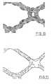
- Variant C of the knitted fabric, shown in Figure 3has differently sized openings or pores, the area of the large pores being greater than 0.5 mm 2 and that of the smaller pores being less than 0.5 mm 2 .
- Variants D and E of the knitted fabric, shown in Figures 4 and 5have other structures.
- Table 1Given in Table 1 are data for the individual variants A to E of the flexible basic structure of the areal implant according to the invention and, for comparison, the corresponding data for a conventional implant net.
- Variants A to Eare all knitted from multifilament polypropylene, using three thread systems.
- the conventional implant netconsists of monofilament polypropylene, using one thread system.
- Table 1shows the number of courses per centimetre, the number of wales per centimetre, the yarn fineness, the dimensions of the pores larger than 0.5 mm 2 , the proportion of pores (relative to the total area of the knitted fabric or of the conventional implant net) and the thickness.
- variants A and Bhave a larger proportion of pores and a smaller thickness.
- variants A to Ehave a relatively low areal weight, which in all cases is below 50 g/m 2 and is thus clearly smaller than that of the conventional implant net.
- the seam tear-out force per centimetre of seam length, measured along and across the knitted fabric or the conventional implant net,is as a rule more than 16 N/cm, the value quoted by Klinge for the maximum wall stress at the edge of an abdominal tissue region.
- the stress-strain behaviour of the knitted fabrics or of the conventional implant netcan be best described quantitatively using a plunger pressing test related to DIN 54307.
- material properties related to areaare measured with such plunger pressing tests.
- Figure 6shows a schematic view of a device for carrying out plunger pressing tests.
- a semispherical plunger 1, which is attached to a shank 2,is moved in the direction of the arrow, i.e. along the axis of symmetry.
- a sample 5 of the knitted fabric to be investigated or of a conventional implant netis clamped between an upper ring 3 and a lower ring 4.
- the plunger 1When the plunger 1 is advanced in a downwards direction, it pushes the sample 5 in a downwards direction. The greater the deformation of the sample 5, the greater the force F exerted on the plunger 1 by the sample 5 becomes.
- the plunger radiusis 50 mm.
- the internal radius of the upper ring 3 and of the lower ring 4is 56.4 mm, so that the effective surface area of the sample 5 is 100 cm 2 .
- the deformation given in Table 1arises which results from the change in length of the sample at r contact measured in the peripheral direction, relative to the corresponding peripheral length of the non-deformed sample. From the test data, it is also possible to calculate the elongation at break, also given in Table 1, which is higher than the deformation since the sample in the plunger pressing test tears, not at r contact , but in the middle region where it is more stretched than at r contact .
- Table 1also shows the results of a strip tensile test carried out on samples of variants A to E and the conventional implant net. For this, the tearing force per centimetre of sample width (tearing strength) along the sample direction and the elongation at break are determined. It is, however, to be taken into consideration here that the values can be severely distorted by the test (contraction upon drawing), making the plunger pressing test more informative.
- the tearing strengthslie in the range from 25 to 45 N/cm and are therefore at least as large as the tearing strength of the fasciae quoted by Klinge (20 to 30 N/cm). The much higher tearing strength of the conventional implant net is again not necessary.
- Figure 7shows a complete plunger force - plunger path length diagram, determined using a plunger pressing test, for the knitted fabric of variant B compared with the conventional implant net made of polypropylene (H).
- the plunger force - plunger path length diagrams as in Figure 7can be converted into force-length change diagrams or into stress-strain diagrams. In the case of the latter, stress is to be understood as the force per centimetre of sample width.
- Figure 8shows such a stress - strain diagram of the flexible basic structure according to variant A, as results from the plunger pressing test.
- a stress - strain diagram determined using rat musculatureis also shown, which was not, however, obtained by a plunger pressing test, which was not possible to carry out with rat musculature because of the sample size required, but on the basis of a strip tensile test on a sample strip approx. 1 cm in width. Measurements on the rat musculature were taken at a musculature thickness which corresponds approximately to that of a human abdominal wall, wherein the spread, as in the case of any biological sample, can be correspondingly large.
- the forces required for variant Aare smaller than for rat musculature, and for elongations of less than 50 %, even much smaller.
- a knitted fabric according to variant A implanted into musclestretches with it during usual movements, without appreciable forces being necessary for this. Therefore, the implant does not have an inconvenient effect.
- the knitted fabric of the basic structureundergoes less pronounced further stretching than the tissue, so that the knitted fabric of the basic structure is able to absorb the forces.
- the transition between the two elongation or stretching regionstakes place at a critical force which results from the point of intersection of the curves in Figure 8.
- the critical force defined in this wayshould be below the highest load which is allowable for the tissue region.
- Table 2shows the plunger forces F measured in the plunger pressing test as a function of the plunger path length s for variants A to E, i.e. values as are shown graphically in Figure 7 for variant B.
- the values for the conventional implant net made of polypropylene (H) according to Table 1 and for another conventional implant net made of polyester (M)are also listed.
- the data for F max and for the plunger path length at F maxare taken from Table 1. In the plunger pressing test initial damage to the investigated sample takes place at F max .
- F maxis much larger for the conventional implant net made of polypropylene than for variants A to E.
- F max for the conventional implant net made of polyesteris of the same order of magnitude as for variants A to E.
- the plunger force for variants A to Eis much smaller than for the conventional implant net made of polyester, which again illustrates the superiority of the implant according to the invention.
- the forcewas not returned to zero in the plunger pressing tests (as in Figure 9), but operated at a residual force of 0.5 N. It is clear from Table 3 that variant B of the flexible basic structure of the implant according to the invention offers a clearly lower resistance to the alternating load, which is to simulate the movement of an abdominal wall, than do the conventional implant nets.
- Figure 10shows a magnified schematic view of the flexible basic structure according to variant A, into which a multifilament thread made of polyglactin 910 is woven for stiffening.
- Figure 11Shown in Figure 11 is a magnified schematic view of the flexible basic structure according to variant B which is provided with a coating of polyglactin 630.
- Polyglactin 630is a copolymer of glycolide and lactide in the ratio 6:3 and, just like polyglactin 910, is resorbable.
- the flexible basic structureis stiffened by the woven-in thread or by the coating, as a result of which handling of the implant according to the invention during use, in particular during the operation, is much improved. Since the stiffening material is resorbable, the rigidity of the implant in the body of the patient decreases with time, until the implant has achieved the properties of the basic structure with its favourable stress/strain behaviour, as explained earlier.
- Table 4compares the bending resistances of the knitted fabric according to variant A ( Figure 1), of the knitted fabric according to variant B ( Figure 2), of the knitted fabric according to variant A with stiffening thread (Figure 10), of the knitted fabric according to variant B with stiffening coating ( Figure 11) and of a conventional implant net made of polypropylene.
- the bending resistances quotedwere determined in a three-point bending test with the supports 15 mm apart and a sample width of 15 mm.
- the conventional implantrated as good by users as regards handling, has a bending resistance of ca. 0.15 to 0.20 N/mm.
- the bending resistances of the stiffened knitted fabricsare clearly higher than those of the original basic structures and are between ca. 0.05 and 0.42 N/mm.
- the initial rigidity of the areal implant according to the inventioncan be varied within wide limits by means of the type, the quantity and the structure of the applied or incorporated stiffening resorbable material.
Landscapes
- Health & Medical Sciences (AREA)
- Public Health (AREA)
- Animal Behavior & Ethology (AREA)
- Heart & Thoracic Surgery (AREA)
- Veterinary Medicine (AREA)
- Vascular Medicine (AREA)
- General Health & Medical Sciences (AREA)
- Life Sciences & Earth Sciences (AREA)
- Epidemiology (AREA)
- Surgery (AREA)
- Engineering & Computer Science (AREA)
- Chemical Kinetics & Catalysis (AREA)
- Chemical & Material Sciences (AREA)
- Textile Engineering (AREA)
- Cardiology (AREA)
- Oral & Maxillofacial Surgery (AREA)
- Transplantation (AREA)
- Biomedical Technology (AREA)
- Prostheses (AREA)
- Materials For Medical Uses (AREA)
Description
- The invention relates to an areal implant, in particular forabdominal wall closure.
- During an operation in the abdominal region, it is oftennecessary to strengthen the abdominal wall using an insertedareal implant. It is known to use nets made from the non-resorbableplastics polypropylene or polyester or from theslowly resorbable polyglactin 910 (a copolymer of glycolide andlactide in the ratio 9:1) for such implants. Metallic implantsare also used.
- The known implant nets have some disadvantages. For example,they are relatively heavy, i.e. the areal weight is as a rulemore than 50 g/m2 and predominantly even ca. 100 g/m2. If theimplants are not resorbable, a relatively large quantity offoreign substance thus remains permanently in the body. Interms of tearing strength, the known implant nets are frequentlyover-sized, i.e. they have a much higher strength than isrequired from a physiological viewpoint. These properties,combined with the usual, net-like construction of the basicstructure of the previously known implants, can mean that thewell-being and the mobility of a patient who is fitted with suchan implant are limited.
- Another disadvantage of the previously known areal implants isthat, although they conform better to the abdominal wall afterthe operation if they are more flexible, they can then only beinserted with difficulty, since e.g. they fold readily. On theother hand, although a rigid implant is easy to handle, it canlead to problems in the long term after insertion into theabdominal wall, as already mentioned. The previously knownareal implants are thus either too flexible for ease of workingduring an operation or too rigid for an unproblematicalinteraction with the abdominal wall into which they areinserted.
- DE 38 30 005 C discloses a conventional areal implant made fromresorbable materials having different melting points, in whichknitted or woven fabric is heated to a temperature above thelowest, but below the highest melting point of the constituents.This implant is porous and can be easily handled, but generallyis not very flexible.
- It is thus the object of the invention to provide an arealimplant, in particular for abdominal wall closure, which can beworked easily during an operation and which shows an elasticitybehaviour in the long term which is matched to the tissue intowhich it is inserted.
- This object is achieved by an areal implant, in particular forabdominal wall closure, having the features of
claim 1.Advantageous embodiments result from the dependent claims. - The areal implant according to the invention has a flexiblebasic structure made from a knitted fabric comprising non-resorbablematerial or resorbable material or a combination ofsuch materials. If resorbable material is used, the resorptiontime (i.e. the period after which the total mass of the implanthas degraded in vivo) is at least 60 days, and/or the in vivodecrease in strength is so slow that 30 days after implantation the tearing strength is still at least 10 % of the initialtearing strength. Non-resorbable or slowly resorbable materialsare used in order that the basic structure is stable in thelonger term and a more certain healing success can be ensured.
- The term "knitted fabric" is to be understood here in the widestsense. It also includes, for example, knits and other mesh structures, i.e. essentially all textile materials which are notpure woven fabrics.
- The knitted fabric of the basic structure is designed to stretchmore than the tissue region destined to receive the implantbelow a critical force and stretch less than this tissue regionabove the critical force. The critical force is below thehighest load this tissue region can be submitted to. Theflexible basic structure is thereby matched without problems tothe usual movements of the tissue (e.g. of an abdominal wall)into which the areal implant is inserted or sewn. In the caseof small forces, as occur during normal movements by thepatient, the elasticity behaviour of the system consisting of anabdominal wall and the inserted implant is shaped by theabdominal wall. The implant thus does not act as a foreignbody. If, on the other hand, the forces exceed the criticalforce, the implant absorbs the forces and thus prevents injuryto the body tissue, e.g. the abdominal wall.
- According to the invention, the basic structure is stiffened bya synthetic resorbable material whose resorption time is lessthan that of the basic structure and preferably lies in therange from 2 days to 200 days. As a result, the areal implantis relatively firm and easy to handle during the operation (e.g.when cutting to size and inserting) but loses its then undesiredrigidity after a relatively short time in the body tissue,because the stiffening synthetic material is resorbed.
- In a preferred version, the knitted fabric of the basicstructure is constructed in such a way that it has stress/strainproperties which can be quantified using a plunger pressingtest, as stated in
claim 2. - The areal weight of the basic structure is preferably less than50 g/m2. When suitable materials are used (see below), for animplant for abdominal wall closure of correspondingly low mass, a strength can be achieved which lies above the physiologicalframework data given by Klinge (U. Klinge, B. Klosterhalten, W.Limberg, A.P. bttinger, V. Schumpelick: Use of mesh materials inscar rupture; Change in the abdominal wall dynamics after meshimplantation; Poster, 162nd Convention of the Lower Rhine-WestphalianSurgeon's Association, 1995). According to him, theintra-abdominal pressure is 20 kPa (150 mm Hg) at most, the wallstress at the edge of an abdominal tissue region 16 N/cm at mostand the tearing strength of the fasciae, 20 N/cm to 30 N/cm. Animplant constructed in this way is thus able to absorb allforces occurring physiologically at a healthy abdominal wall andalso offers an additional safety reserve. More stable and thusheavier basic structures offer no additional advantage, but canhave the disadvantage of undesired rigidity mentioned at thebeginning.
- The knitted fabric of the basic structure preferably has anapproximate rectangular structure or approximate quadraticstructure knitted from yarns. Honeycomb structures orstructures with approximately circular openings or otherpolygonal structures are however also conceivable. Preferredversions of such knitted fabrics are explained in more detail inthe description of the embodiments with the help of figures.The desired stress/strain behaviour can be achieved with knittedstructures of this type, i.e. the basic structure stretches morethan the tissue region destined to receive the implant below thecritical force and less than this tissue region above thecritical force, the critical force being below the highest loadallowable for this tissue region.
- There are various possibilities for connecting the stiffeningmaterial to the basic structure. Thus, the stiffening materialcan e.g. have resorbable yarns or thin monofilaments woven intothe basic structure, it can have a film which is applied to oneside or both sides of the basic structure, or it can have a coating applied to the material of the knitted fabric.Combinations of these are also conceivable.
- Advantageous materials for the basic structure are e.g.polypropylene, polyester, polyglactin 910, polylactide yarns,polyglycolide yarns, poly-p-dioxanone yarns, but alsocopolymers, mixtures or combinations of such materials.
- Suitable as the stiffening material are e.g. yarns or films ofpoly-p-dioxanone, yarns or films of polyglactin (i.e.glycolide/lactide copolymers), yarns or films of polylactide,yarns or films of other copolymers of these materials,monofilaments of such materials (e.g. with thread thicknesses of0.01 mm to 0.2 mm in diameter), coating waxes made from suchmaterials, in particular from polyglactin 630, and others.Mixtures of synthetic resorbable materials whose resorption timelies in the desired range can also be used for the stiffeningmaterial. If the stiffening material is of a textile nature,the result of the in vivo decrease in strength is that, afteran implantation time of typically 2 to 50 days, the residualtearing strength is still about 10 % of the initial tearingstrength.
- The material of the basic structure is preferably not dyed, inorder that the basic structure, which does after all remain inthe body for a long time or permanently after implantation,shows no undesired foreign body reaction as a result of the dye.On the other hand, it can be advantageous if the stiffeningmaterial is dyed. This does in fact permit a better visual checkon the implant during the operation. During resorption the dyedisappears, so that no dye remains in the body in the longerterm and thus no undesired side-effects occur.
- The invention is described in more detail below with referenceto embodiments and with the help of drawings. These show:
- Figure 1
- a magnified schematic view of a first version of theflexible basic structure (variant A), magnified 25times in part (a) and 15 times in part (b),
- Figure 2
- a magnified (25 times) schematic view of anotherversion of the flexible basic structure (variant B),
- Figure 3
- a magnified (25 times) schematic view of anotherversion of the flexible basic structure (variant C),
- Figure 4
- a magnified (25 times) schematic view of anotherversion of the flexible basic structure (variant D),
- Figure 5
- a magnified (25 times) schematic view of anotherversion of the flexible basic structure (variant E),
- Figure 6
- a schematic view of a device for carrying out plungerpressing tests,
- Figure 7
- the plunger force - plunger path length diagram,measured with the device according to Figure 6, of theflexible basic structure according to variant Bcompared with a conventional implant made ofpolypropylene (H),
- Figure 8
- the stress-strain diagram of the flexible basicstructure according to variant A, compared with ratmusculature,
- Figure 9
- a schematic plunger force - plunger path lengthdiagram to explain the hysteresis behaviour of theflexible basic structure,
- Figure 10
- a magnified (25 times) schematic view of the flexiblebasic structure according to variant A which isstiffened with a yarn made of polyglactin 910, and
- Figure 11
- a magnified (25 times) schematic view of the flexiblebasic structure according to variant B which isstiffened with a resorbable coating made ofpolyglactin 630.
- Figures 1 to 5 show magnified schematic views of differentversions of the knitted fabric of the flexible basic structureof the areal implant according to the invention. The figuresare drawn on the basis of scanning electron microscopephotographs taken at roughly 25 times magnification.
- Variant A of the knitted fabric according to Figure 1 has anapproximate quadratic structure, the crosspiece length beingabout 3 mm in each case. Variant B of the knitted fabricaccording to Figure 2 also has an approximate quadraticstructure. However, the crosspiece length is larger here and isabout 5 mm. Variant C of the knitted fabric, shown in Figure 3,has differently sized openings or pores, the area of the largepores being greater than 0.5 mm2 and that of the smaller poresbeing less than 0.5 mm2. Variants D and E of the knitted fabric,shown in Figures 4 and 5, have other structures.
- It is clearly recognisable from Figures 1 to 5 that the majorityof the pores are larger than 0.5 mm2. Thus, after implantation,the flexible basic structure of the areal implant can be grownthrough by tissue in satisfactory manner, which leads to asecure anchorage in the body of the patient and to a reliableabsorption of forces by the implant.

- Given in Table 1 are data for the individual variants A to E ofthe flexible basic structure of the areal implant according tothe invention and, for comparison, the corresponding data for aconventional implant net.
- Variants A to E are all knitted from multifilamentpolypropylene, using three thread systems. The conventionalimplant net consists of monofilament polypropylene, using onethread system. Table 1 shows the number of courses percentimetre, the number of wales per centimetre, the yarnfineness, the dimensions of the pores larger than 0.5 mm2, theproportion of pores (relative to the total area of the knittedfabric or of the conventional implant net) and the thickness.Compared with the conventional implant net, variants A and Bhave a larger proportion of pores and a smaller thickness. AsTable 1 also shows, variants A to E have a relatively low arealweight, which in all cases is below 50 g/m2 and is thus clearlysmaller than that of the conventional implant net.
- For variants A to E, the seam tear-out force per centimetre ofseam length, measured along and across the knitted fabric or theconventional implant net, is as a rule more than 16 N/cm, thevalue quoted by Klinge for the maximum wall stress at the edgeof an abdominal tissue region.
- The stress-strain behaviour of the knitted fabrics or of theconventional implant net can be best described quantitativelyusing a plunger pressing test related to DIN 54307. In thetextile industry, material properties related to area aremeasured with such plunger pressing tests.
- Figure 6 shows a schematic view of a device for carrying outplunger pressing tests. A
semispherical plunger 1, which isattached to ashank 2, is moved in the direction of the arrow,i.e. along the axis of symmetry. Asample 5 of the knittedfabric to be investigated or of a conventional implant net is clamped between anupper ring 3 and alower ring 4. When theplunger 1 is advanced in a downwards direction, it pushes thesample 5 in a downwards direction. The greater the deformationof thesample 5, the greater the force F exerted on theplunger 1 by thesample 5 becomes. The force F and the plunger pathlength s, which is a measure of the deformation of thesample 5,are measured, wherein s = 0 when the lowest point of theplunger 1 is located in the plane of thesample 5. With the device usedfor the plunger pressing tests the plunger radius is 50 mm. Theinternal radius of theupper ring 3 and of thelower ring 4 is56.4 mm, so that the effective surface area of thesample 5 is100 cm2. - Given in Table 1 for variants A to E and for the conventionalimplant net are the maximum force Fmax applied during the plungerpressing test, at which the first damage to the sample occurs(in the middle region of the sample), and the associated plungerpath length smax. From this, the so-called stress at rcontact,which corresponds to the so-called wall stress in N/cm, can becalculated. In the sample, the stress at rcontact occurs along thecircular line where, in the case of plunger path length smax, thesample region abutting the plunger passes into the sample edgeregion which does not touch the plunger directly and extends asfar as the
rings - It is clear from Table 1 that for all variants A to E the stressat rcontact is greater than or equal to 16 N/cm, i.e. at least aslarge as the maximum wall stress at the edge of an abdominal tissue region (16 N/cm) quoted by Klinge. The much greater valuein the case of the conventional implant net is physiologicallyunnecessary.
- Table 1 also shows the results of a strip tensile test carriedout on samples of variants A to E and the conventional implantnet. For this, the tearing force per centimetre of sample width(tearing strength) along the sample direction and the elongationat break are determined. It is, however, to be taken intoconsideration here that the values can be severely distorted bythe test (contraction upon drawing), making the plunger pressingtest more informative.
- For variants A to E of the knitted fabric, the tearing strengthslie in the range from 25 to 45 N/cm and are therefore at leastas large as the tearing strength of the fasciae quoted by Klinge(20 to 30 N/cm). The much higher tearing strength of theconventional implant net is again not necessary.
- Figure 7 shows a complete plunger force - plunger path lengthdiagram, determined using a plunger pressing test, for theknitted fabric of variant B compared with the conventionalimplant net made of polypropylene (H). The curve for variant Bends at the values for Fmax and smax given in Table 1, whilst thecurve for the conventional implant net is not shown in full, butstops at F = 500 N. It is clear to see that, for the implant ofthe invention according to variant B, the plunger force F issmall even with relatively large plunger path lengths s. Onlyat larger values of s does the curve rise sharply. With theconventional implant net, the plunger force F is already largeat average plunger path lengths s.
- The plunger force - plunger path length diagrams as in Figure 7can be converted into force-length change diagrams or intostress-strain diagrams. In the case of the latter, stress is tobe understood as the force per centimetre of sample width.
- Moreover, the change in length of the sample is related to thetotal length of the sample (before strain) and is thusindependent of the total length of the sample itself. Figure 8shows such a stress - strain diagram of the flexible basicstructure according to variant A, as results from the plungerpressing test.
- A stress - strain diagram determined using rat musculature isalso shown, which was not, however, obtained by a plungerpressing test, which was not possible to carry out with ratmusculature because of the sample size required, but on thebasis of a strip tensile test on a sample strip approx. 1 cm inwidth. Measurements on the rat musculature were taken at amusculature thickness which corresponds approximately to that ofa human abdominal wall, wherein the spread, as in the case ofany biological sample, can be correspondingly large.
- A narrow sample strip contracts in the tensile test, which leadsto a much greater elongation at a given tensile force per stripwidth (stress) than if elongation takes place simultaneously inseveral spatial directions, as during the plunger pressing test.The curve for the rat musculature cannot therefore be compareddirectly with the stress - strain diagram obtained in theplunger pressing test for the flexible basic structure accordingto variant A. For this reason, another stress-strain diagram isshown for the flexible basic structure according to variant Awhich, as with the rat musculature, was determined using a striptensile test, using a
sample strip 1 cm in width. Even at anelongation of 100 %, the sample had still not torn, which is notinconsistent with the elongation at break given in Table 1 forthe strip tensile test, because the values in Table 1 apply tostrips with a larger width. - In order to achieve an elongation up to about 78 %, the forcesrequired for variant A are smaller than for rat musculature, andfor elongations of less than 50 %, even much smaller. This means that a knitted fabric according to variant A implantedinto muscle stretches with it during usual movements, withoutappreciable forces being necessary for this. Therefore, theimplant does not have an inconvenient effect. However, if inthe case of extreme loads, the forces which arise approach thehighest load which is allowable for the tissue region into whichthe implant is inserted (which corresponds in Figure 8 to about18 N/cm), the knitted fabric of the basic structure undergoesless pronounced further stretching than the tissue, so that theknitted fabric of the basic structure is able to absorb theforces. The transition between the two elongation or stretchingregions takes place at a critical force which results from thepoint of intersection of the curves in Figure 8. The criticalforce defined in this way should be below the highest load whichis allowable for the tissue region.
- The fact that in Figure 8 the critical force and the highestload which is allowable for the tissue region (to be moreprecise, the corresponding stresses) are approximately the samesize is due to the tests with rat musculature which aredifficult to carry out. Figure 8 is intended only to illustratethe two described elongation regions. Quantitative measurementson the flexible basic structures are better carried out usingplunger pressing tests, and Klinge's data can for example bereferred to for tissue, see above.
- Table 2 shows the plunger forces F measured in the plungerpressing test as a function of the plunger path length s forvariants A to E, i.e. values as are shown graphically in Figure7 for variant B. By way of comparison, the values for theconventional implant net made of polypropylene (H) according toTable 1 and for another conventional implant net made ofpolyester (M) are also listed. The data for Fmax and for theplunger path length at Fmax are taken from Table 1. In theplunger pressing test initial damage to the investigated sampletakes place at Fmax.
Plunger force F measured in the plunger pressing test related to DIN 54307 as a function of the plunger path length s, and Fmax (in N) and s(Fmax) (in mm) for five flexible basic structures according to the invention (variants A to E) and for two conventional implant nets made of polypropylene (H) and of polyester (M). A B C D E M H s [mm] F[N] F[N] F[N] F[N] F[N] F[N] F[N] 10 < 10 < 10 < 10 < 10 < 10 ca.10 ca.50 15 ca.15 ca.20 ca.10 ca.20 ca.10 ca.35 ca.135 20 ca.30 ca.35 ca.30 ca.40 ca.40 ca.85 ca.300 25 ca.70 ca.70 ca.75 ca.80 ca.80 ca.160 ca.600 30 ca.130 ca.130 ca.150 ca.170 ca.150 ca.280 Fmax 464 420 460 490 630 460 2370 s(Fmax) 45 44 40 41 45 37 45 - As already seen, Fmax is much larger for the conventional implantnet made of polypropylene than for variants A to E. Fmax for theconventional implant net made of polyester is of the same orderof magnitude as for variants A to E. However, for the plungerpath lengths up to 30 mm listed in Table 2, the plunger forcefor variants A to E is much smaller than for the conventionalimplant net made of polyester, which again illustrates thesuperiority of the implant according to the invention.
- Both the knitted fabric of the basic structure of the arealimplant according to the invention and conventional implant netsshow a hysteresis behaviour which can be determined in theplunger pressing test. The plunger force - plunger path lengthdiagram in Figure 9 shows schematically how in the case of a newsample, the plunger force F, starting from the plunger pathlength s = 0, increases to a value F0 which is defined here asthe value of the plunger force at a plunger path length of 20mm. If the plunger is withdrawn, the plunger force alreadyreturns to zero at a plunger path length s1.
- Table 3 compares the force F0 and the plunger path length s1during one plunger pressing test (n = 1) and after 5,000 plungerpressing tests (n = 5,000) for a conventional implant net madeof polyglactin 910, a conventional implant net made ofpolypropylene and the knitted fabric of the basic structureaccording to variant B. In order to ensure a secure abutment ofthe sample against the plunger, the force was not returned tozero in the plunger pressing tests (as in Figure 9), butoperated at a residual force of 0.5 N. It is clear from Table3 that variant B of the flexible basic structure of the implantaccording to the invention offers a clearly lower resistance tothe alternating load, which is to simulate the movement of anabdominal wall, than do the conventional implant nets.
Hysteresis behaviour of different implants after n alternating loads, measured in the plunger pressing test at a plunger path length between 0 and 20 mm and a plunger residual force of 0.5 N; see text Implant n = 1 n = 5000 F0 [N] s1 [mm] F0 [N] s1 [mm] Conventional implant net made of polyglactin 910, coarse-meshed ca. 150 ca. 8 ca.114 ca.15.5 Conventional implant net made of polypropylene ca. 240 ca. 4 ca.164 ca.12.5 Basic structure according to the invention, variant B ca.45 ca.7.5 ca.30 ca.14.2 - Figure 10 shows a magnified schematic view of the flexible basicstructure according to variant A, into which a multifilamentthread made of polyglactin 910 is woven for stiffening. Shown inFigure 11 is a magnified schematic view of the flexible basic structure according to variant B which is provided with acoating of polyglactin 630. Polyglactin 630 is a copolymer ofglycolide and lactide in the ratio 6:3 and, just likepolyglactin 910, is resorbable.
- The flexible basic structure is stiffened by the woven-in threador by the coating, as a result of which handling of the implantaccording to the invention during use, in particular during theoperation, is much improved. Since the stiffening material isresorbable, the rigidity of the implant in the body of thepatient decreases with time, until the implant has achieved theproperties of the basic structure with its favourablestress/strain behaviour, as explained earlier.
- Table 4 compares the bending resistances of the knitted fabricaccording to variant A (Figure 1), of the knitted fabricaccording to variant B (Figure 2), of the knitted fabricaccording to variant A with stiffening thread (Figure 10), ofthe knitted fabric according to variant B with stiffeningcoating (Figure 11) and of a conventional implant net made ofpolypropylene. The bending resistances quoted were determinedin a three-point bending test with the
supports 15 mm apart anda sample width of 15 mm. The conventional implant, rated asgood by users as regards handling, has a bending resistance ofca. 0.15 to 0.20 N/mm. The bending resistances of the stiffenedknitted fabrics are clearly higher than those of the originalbasic structures and are between ca. 0.05 and 0.42 N/mm. Thelatter value is even much higher than that for the previouslyknown implant net.Bending resistance of different implants, determined by comparative measurement in the three-point bending test with the supports 15 mm apart and a sample width of 15 mmImplant Bending resistance [N/mm] Basic structure according to the invention, variant A ca. 0.03 Basic structure according to the invention, variant B ca. 0.015 Basic structure according to the invention, variant A, stiffened by yarn (4 x 80 den) made of polyglactin 910 ca. 0.05 Basic structure according to the invention, variant B, stiffened by coating made of polyglactin 630 ca. 0.42 Conventional implant net made of polypropylene ca. 0.15 to 0.2 - The initial rigidity of the areal implant according to theinvention can be varied within wide limits by means of the type,the quantity and the structure of the applied or incorporatedstiffening resorbable material.

Claims (16)
- Areal implant, in particular for abdominal wall closure,with a flexible basic structure made from a knittedfabric comprising non-resorbable material or resorbablematerial, which has a resorption time of at least 60 daysand/or an in vivo decrease in strength which leads to atearing strength remaining after 30 days which is at least10 % of the initial tearing strength, or a combination ofsuch materials,wherein the knitted fabric of the basic structure isdesigned to stretch more than the tissue region destined toreceive the implant below a critical force and stretch lessthan this tissue region above the critical force, thecritical force being below the highest load allowable forthis tissue region, andwith a synthetic resorbable material, which stiffens thebasic structure, whose resorption time is less than that ofthe basic structure.
- Areal implant according to Claim 1,characterized in thatthe knitted fabric of the basic structure is constructed insuch a way that a plunger pressing test carried out on animplant 100 cm2 in area with semispherical plunger 50 mm inradius produces a plunger force-plunger path length diagramwhich corresponds to a force-length change diagram, inwhich the plunger force is at most 15 N up to 10 mm plungerpath length, less than 50 N at 20 mm plunger path length,and less than 200 N at 30 mm plunger path length, and inwhich the plunger force for plunger path lengths of morethan 30 mm increases sharply to a value between 200 N and1000 N at a plunger path length of 38 mm.
- Areal implant according to Claim 1 or 2,characterized inthat the resorption time of the stiffening material is 2days to 200 days.
- Areal implant according to one of claims 1 to 3,characterized in that the areal weight of the basicstructure is less than 50 g/m2.
- Areal implant according to one of claims 1 to 4,characterized in that the knitted fabric has a honeycombstructure or approximate rectangular structure orapproximate quadratic structure knitted from yarns.
- Areal implant according to one of claims 1 to 4,characterized in that the knitted fabric has a structure asis shown in one of Figures 1 to 5.
- Areal implant according to one of the preceding claims,characterized in that the knitted fabric has meshes with aninside width in the range from 1 mm to 8 mm.
- Areal implant according to one of the preceding claims,characterized in that the stiffening material hasresorbable yarns, preferably monofilaments and/ormultifilaments, knitted into the basic structure.
- Areal implant according to one of the preceding claims,characterized in that the stiffening material has a filmwhich is applied to one side or both sides of the basicstructure.
- Areal implant according to one of the preceding claims,characterized in that the stiffening material has a coatingapplied to the material of the knitted fabric.
- Areal implant according to Claim 10,characterized in thatthe coating comprises polyglactin 630.
- Areal implant according to one of the preceding claims,characterized in that the stiffening material comprises a material which is selected from the following group ofmaterials: polymers based on caprolactone, polyglycolide,polylactide, poly-p-dioxanone, lactide/glycolidecopolymers, lactide/caprolactone copolymers,glycolide/caprolactone copolymers, glycolide/poly-p-dioxanonecopolymers, glycolide/poly-p-dioxanone/lactide copolymers,other copolymers of the listed materials.
- Areal implant according to one of the preceding claims,characterized in that the material of the basic structurecomprises polypropylene and/or polyester.
- Areal implant according to one of the preceding claims,characterized in that the material of the basic structurecomprises a material which is selected from the group ofthe following materials: polylactide, polyglycolide,lactide/glycolide copolymers, preferably polyglactin 910,poly-p-dioxanone.
- Areal implant according to one of the preceding claims,characterized in that the material of the basic structureis not dyed.
- Areal implant according to one of the preceding claims,characterized in that the stiffening material is dyed.
Applications Claiming Priority (2)
| Application Number | Priority Date | Filing Date | Title |
|---|---|---|---|
| DE19613730ADE19613730C2 (en) | 1996-03-26 | 1996-03-26 | Flat implant for strengthening or closing body tissue |
| DE19613730 | 1996-03-26 |
Publications (4)
| Publication Number | Publication Date |
|---|---|
| EP0797962A2 EP0797962A2 (en) | 1997-10-01 |
| EP0797962A3 EP0797962A3 (en) | 1997-11-05 |
| EP0797962B1true EP0797962B1 (en) | 2004-05-12 |
| EP0797962B2 EP0797962B2 (en) | 2009-09-02 |
Family
ID=7790607
Family Applications (1)
| Application Number | Title | Priority Date | Filing Date |
|---|---|---|---|
| EP97250072AExpired - LifetimeEP0797962B2 (en) | 1996-03-26 | 1997-03-13 | Areal implant |
Country Status (9)
| Country | Link |
|---|---|
| US (1) | US6162962A (en) |
| EP (1) | EP0797962B2 (en) |
| JP (1) | JP4450437B2 (en) |
| CN (1) | CN1163196C (en) |
| AU (1) | AU704334B2 (en) |
| BR (1) | BR9701466B8 (en) |
| CA (1) | CA2200801C (en) |
| DE (2) | DE19613730C2 (en) |
| ZA (1) | ZA972563B (en) |
Cited By (14)
| Publication number | Priority date | Publication date | Assignee | Title |
|---|---|---|---|---|
| WO2007101630A1 (en) | 2006-03-09 | 2007-09-13 | Aesculap Ag | Flat implant, particularly a hernia mesh |
| EP2070555A2 (en) | 2007-12-14 | 2009-06-17 | Aesculap AG | Fluorinated implant |
| EP2072023A1 (en) | 2007-12-20 | 2009-06-24 | Aesculap AG | Flat implant, in particular for supplying hernias |
| US7594921B2 (en) | 2001-03-30 | 2009-09-29 | Mpathy Medical Devices Limited | Surgical implant |
| US7789821B2 (en) | 2000-10-12 | 2010-09-07 | Gyne Ideas Ltd. | Apparatus and method for treating female urinary incontinence |
| US7975698B2 (en) | 2004-05-21 | 2011-07-12 | Coloplast A/S | Implant for treatment of vaginal and/or uterine prolapse |
| US8016841B2 (en) | 2007-06-11 | 2011-09-13 | Novus Scientific Pte. Ltd. | Mesh implant with an interlocking knitted structure |
| US8167785B2 (en) | 2000-10-12 | 2012-05-01 | Coloplast A/S | Urethral support system |
| US8469875B2 (en) | 2000-07-05 | 2013-06-25 | Coloplast A/S | Method and device for treating urinary incontinence |
| US8709471B2 (en) | 2003-03-27 | 2014-04-29 | Coloplast A/S | Medicament delivery device and a method of medicament delivery |
| US8906047B2 (en) | 2006-06-22 | 2014-12-09 | Novus Scientific Ab | Mesh implant for use in reconstruction of soft tissue defects |
| US9186235B2 (en) | 2000-04-20 | 2015-11-17 | Sofradim Production | Prosthetic knit with grip properties, method for its production, and reinforcement implant for treatment of parietal defects |
| US9242026B2 (en) | 2008-06-27 | 2016-01-26 | Sofradim Production | Biosynthetic implant for soft tissue repair |
| US9308068B2 (en) | 2007-12-03 | 2016-04-12 | Sofradim Production | Implant for parastomal hernia |
Families Citing this family (117)
| Publication number | Priority date | Publication date | Assignee | Title |
|---|---|---|---|---|
| FR2732582B1 (en)* | 1995-04-04 | 1997-10-17 | Sgro Jean Claude | PARIETAL PROSTHETIC ELEMENT |
| US7238403B2 (en)* | 1997-03-07 | 2007-07-03 | Kx Industries, Lp | Composite for removing moisture, liquid and odors with anti-microbial capability |
| US5980564A (en)* | 1997-08-01 | 1999-11-09 | Schneider (Usa) Inc. | Bioabsorbable implantable endoprosthesis with reservoir |
| FR2766698B1 (en) | 1997-08-01 | 1999-11-05 | Cogent Sarl | ADJUSTED THREE-DIMENSIONAL PROSTHETIC FABRIC |
| FR2767671B1 (en) | 1997-08-27 | 1999-11-26 | Ethnor | PROSTHETIC SHUTTER DEVICE FOR SHUTTERING HERNARY CHANNELS |
| US6241768B1 (en) | 1997-08-27 | 2001-06-05 | Ethicon, Inc. | Prosthetic device for the repair of a hernia |
| FR2767672B1 (en)* | 1997-08-27 | 1999-11-26 | Ethnor | PROSTHESES FOR SEALING HERNIA CANALS |
| US6319264B1 (en) | 1998-04-03 | 2001-11-20 | Bionx Implants Oy | Hernia mesh |
| US6740122B1 (en) | 1998-09-11 | 2004-05-25 | C. R. Bard, Inc. | Preformed curved prosthesis that is adapted to the external iliac vessels |
| US6723133B1 (en) | 1998-09-11 | 2004-04-20 | C. R. Bard, Inc. | Performed curved prosthesis having a reduced incidence of developing wrinkles or folds |
| DE19906172C1 (en)* | 1999-02-08 | 2000-07-13 | Ethicon Gmbh | Resorbable implant used for inducing tissue formation, especially in bone regeneration, has specific density and porosity properties |
| DE19912360A1 (en) | 1999-03-19 | 2000-09-21 | Aesculap Ag & Co Kg | Strand-shaped implant made of resorbable polymer material, process for its production and use in surgery |
| DE19942611C1 (en)* | 1999-08-31 | 2001-07-05 | Ethicon Gmbh | Reinforced flat implant |
| DE19954166A1 (en) | 1999-11-10 | 2001-05-17 | Inst Textil & Faserforschung | Flat implant, method for its production and use in surgery |
| DE19959088A1 (en)* | 1999-12-08 | 2001-06-13 | Inst Textil & Faserforschung | Medical device, process for its manufacture and use |
| DE10004832A1 (en)* | 2000-01-31 | 2001-08-16 | Ethicon Gmbh | Flat implant with X-ray visible elements |
| FR2807936B1 (en) | 2000-04-20 | 2002-08-02 | Sofradim Production | ABDOMINAL WALL REINFORCEMENT FOR THE TREATMENT OF INGUINAL HERNIA BY ANTERIOR VOLTAGE-FREE |
| DE10043396C1 (en)* | 2000-09-04 | 2002-06-20 | Ethicon Gmbh | Flexible implant |
| US6592515B2 (en) | 2000-09-07 | 2003-07-15 | Ams Research Corporation | Implantable article and method |
| US7025063B2 (en) | 2000-09-07 | 2006-04-11 | Ams Research Corporation | Coated sling material |
| DE10046119A1 (en) | 2000-09-15 | 2002-03-28 | Inst Textil & Faserforschung | Medical bioresorbable implant, method of manufacture and use |
| US20060205995A1 (en) | 2000-10-12 | 2006-09-14 | Gyne Ideas Limited | Apparatus and method for treating female urinary incontinence |
| DE10123934A1 (en) | 2001-05-17 | 2002-12-05 | Ethicon Gmbh | Flat implant |
| AU2002313195B2 (en)* | 2001-06-15 | 2006-05-18 | Gunze Limited | Antiadhesive Material |
| DE10153334B4 (en)* | 2001-10-29 | 2004-04-29 | Ethicon Gmbh | Flat implant |
| DE10155842A1 (en)* | 2001-11-14 | 2003-05-28 | Ethicon Gmbh | Flat implant |
| US6790213B2 (en) | 2002-01-07 | 2004-09-14 | C.R. Bard, Inc. | Implantable prosthesis |
| DE10219860A1 (en)* | 2002-05-03 | 2003-11-20 | Ethicon Gmbh | Surgical thread and surgical implant with such a thread |
| DE10220368A1 (en)* | 2002-05-07 | 2003-12-04 | Biotissue Technologies Ag | Implant comprising transplant tissue cells in a porous resorbable matrix, especially useful for cartilage or bone transplantation, includes one or more stiffening elements for increasing compressive stability |
| US20040059356A1 (en)* | 2002-07-17 | 2004-03-25 | Peter Gingras | Soft tissue implants and methods for making same |
| CA2492630C (en) | 2002-08-02 | 2009-01-13 | C.R. Bard, Inc. | Self anchoring sling and introducer system |
| DE10243967A1 (en)* | 2002-09-20 | 2004-04-15 | Adiam Life Science Ag | Vascular prosthesis or tissue patch made of biocompatible polyurethane and method for improving the elastic modulus of these workpieces |
| US8142515B2 (en)* | 2002-11-04 | 2012-03-27 | Sofradim Production | Prosthesis for reinforcement of tissue structures |
| US8545386B2 (en) | 2003-08-14 | 2013-10-01 | Boston Scientific Scimed, Inc. | Surgical slings |
| US20050070930A1 (en)* | 2003-09-30 | 2005-03-31 | Gene W. Kammerer | Implantable surgical mesh |
| US20050113849A1 (en)* | 2003-11-26 | 2005-05-26 | Nicholas Popadiuk | Prosthetic repair device |
| EP1744796B1 (en) | 2004-04-20 | 2015-03-18 | Genzyme Corporation | Surgical mesh-like implant |
| FR2869234B1 (en)* | 2004-04-21 | 2008-07-18 | Cousin Biotech Soc Par Actions | TEXTILE IMPLANT OF PARIETAL REFECTION |
| US8298290B2 (en) | 2004-09-20 | 2012-10-30 | Davol, Inc. | Implantable prosthesis for soft tissue repair |
| DE602004023742D1 (en)* | 2004-12-23 | 2009-12-03 | Novus Scient Pte Ltd | Tissue implant for use in the reconstruction of soft tissue defects |
| US9566370B2 (en) | 2004-12-23 | 2017-02-14 | Novus Scientific Ab | Mesh implant for use in reconstruction of soft tissue defects |
| US9717825B2 (en) | 2004-12-23 | 2017-08-01 | Novus Scientific Ab | Mesh implant for use in reconstruction of soft tissue defects |
| JP4827838B2 (en) | 2004-12-29 | 2011-11-30 | サムヤン コーポレーション | Monofilament, mesh for deentering surgery with improved flexibility and biocompatibility using the same, and method for producing the same |
| AU2006210494B2 (en) | 2005-02-04 | 2011-01-06 | Ams Research Corporation | Needle design for male transobturator sling |
| DE102005009356A1 (en) | 2005-03-01 | 2006-09-07 | Ethicon Gmbh | Surgical implant |
| JP2008534065A (en)* | 2005-03-22 | 2008-08-28 | タイコ ヘルスケア グループ リミテッド パートナーシップ | Mesh implant |
| EP1861055A4 (en)* | 2005-03-22 | 2013-01-16 | Covidien Lp | Bioactive wide-weave mesh |
| EP1937183B1 (en)* | 2005-09-12 | 2018-11-28 | Proxy Biomedical Limited | Soft tissue implants |
| US7614258B2 (en) | 2006-10-19 | 2009-11-10 | C.R. Bard, Inc. | Prosthetic repair fabric |
| CN101627525B (en) | 2006-12-27 | 2012-06-13 | 东芝开利株式会社 | Winding method for stator, and permanent-magnet electric motor |
| EP2002800B1 (en)* | 2007-06-11 | 2009-09-30 | Novus Scientific Pte. Ltd. | Mesh implant with an interlocking knitted structure |
| EP2185209A2 (en)* | 2007-08-03 | 2010-05-19 | Nicast Ltd. | Fibrous surgically implantable mesh |
| US8206632B2 (en)* | 2007-12-18 | 2012-06-26 | Ethicon, Inc. | Methods of making composite prosthetic devices having improved bond strength |
| JP2012504457A (en) | 2008-10-03 | 2012-02-23 | シー・アール・バード・インコーポレーテッド | Implantable prosthesis |
| FR2949688B1 (en) | 2009-09-04 | 2012-08-24 | Sofradim Production | FABRIC WITH PICOTS COATED WITH A BIORESORBABLE MICROPOROUS LAYER |
| AU2011232414A1 (en) | 2010-03-24 | 2012-11-15 | Covidien Lp | Combination three-dimensional surgical implant |
| US20110301717A1 (en)* | 2010-06-03 | 2011-12-08 | Hilton Becker | Supporting and Forming Transitional Material for Use in Supporting Prosthesis Devices, Implants and to Provide Structure in a Human Body |
| US8821585B2 (en)* | 2010-06-14 | 2014-09-02 | Ethicon, Inc. | Composite anisotropic tissue reinforcing implants having alignment markers and methods of manufacturing same |
| FR2962646B1 (en) | 2010-07-16 | 2012-06-22 | Sofradim Production | PROSTHETIC WITH RADIO OPAQUE ELEMENT |
| US9861590B2 (en) | 2010-10-19 | 2018-01-09 | Covidien Lp | Self-supporting films for delivery of therapeutic agents |
| US9561093B2 (en)* | 2010-10-28 | 2017-02-07 | Novus Scientific Ab | Elastically deformable and resorbable medical mesh implant |
| FR2972626B1 (en)* | 2011-03-16 | 2014-04-11 | Sofradim Production | PROSTHETIC COMPRISING A THREE-DIMENSIONAL KNIT AND ADJUSTED |
| FR2977790B1 (en) | 2011-07-13 | 2013-07-19 | Sofradim Production | PROSTHETIC FOR UMBILIC HERNIA |
| FR2977789B1 (en) | 2011-07-13 | 2013-07-19 | Sofradim Production | PROSTHETIC FOR UMBILIC HERNIA |
| US8579924B2 (en) | 2011-07-26 | 2013-11-12 | Covidien Lp | Implantable devices including a mesh and a pivotable film |
| US9782957B2 (en) | 2011-08-24 | 2017-10-10 | Covidien Lp | Medical device films |
| US9526603B2 (en) | 2011-09-30 | 2016-12-27 | Covidien Lp | Reversible stiffening of light weight mesh |
| US9005308B2 (en) | 2011-10-25 | 2015-04-14 | Covidien Lp | Implantable film/mesh composite for passage of tissue therebetween |
| US9179994B2 (en) | 2011-10-25 | 2015-11-10 | Covidien Lp | Implantable film/mesh composite |
| US8932621B2 (en) | 2011-10-25 | 2015-01-13 | Covidien Lp | Implantable film/mesh composite |
| FR2985271B1 (en) | 2011-12-29 | 2014-01-24 | Sofradim Production | KNITTED PICOTS |
| FR2985170B1 (en) | 2011-12-29 | 2014-01-24 | Sofradim Production | PROSTHESIS FOR INGUINAL HERNIA |
| EP2626454B1 (en) | 2012-02-10 | 2014-08-13 | Novus Scientific AB | Multifilaments with time-dependent characteristics and medical products made thereof |
| US9080263B2 (en) | 2012-02-10 | 2015-07-14 | Novus Scientific Ab | Multifilaments with time-dependent characteristics, and medical products made from such multifilaments |
| US10206769B2 (en) | 2012-03-30 | 2019-02-19 | Covidien Lp | Implantable devices including a film providing folding characteristics |
| CN111419467B (en)* | 2012-04-06 | 2022-11-15 | 聚合-医药有限公司 | Polymer network products, methods of manufacture and uses thereof |
| USD681813S1 (en) | 2012-05-24 | 2013-05-07 | Ams Research Corporation | Implant |
| USD694886S1 (en) | 2012-05-24 | 2013-12-03 | Ams Research Corporation | Implant |
| USD685476S1 (en) | 2012-05-25 | 2013-07-02 | Ams Research Corporation | Implant |
| USD680649S1 (en) | 2012-05-25 | 2013-04-23 | Ams Research Corporation | Implant |
| FR2992662B1 (en) | 2012-06-28 | 2014-08-08 | Sofradim Production | KNIT WITH PICOTS |
| FR2992547B1 (en) | 2012-06-29 | 2015-04-24 | Sofradim Production | PROSTHETIC FOR HERNIA |
| FR2994185B1 (en) | 2012-08-02 | 2015-07-31 | Sofradim Production | PROCESS FOR THE PREPARATION OF A POROUS CHITOSAN LAYER |
| FR2995788B1 (en) | 2012-09-25 | 2014-09-26 | Sofradim Production | HEMOSTATIC PATCH AND PREPARATION METHOD |
| FR2995779B1 (en) | 2012-09-25 | 2015-09-25 | Sofradim Production | PROSTHETIC COMPRISING A TREILLIS AND A MEANS OF CONSOLIDATION |
| FR2995778B1 (en) | 2012-09-25 | 2015-06-26 | Sofradim Production | ABDOMINAL WALL REINFORCING PROSTHESIS AND METHOD FOR MANUFACTURING THE SAME |
| AU2013322268B2 (en) | 2012-09-28 | 2017-08-31 | Sofradim Production | Packaging for a hernia repair device |
| US10709539B2 (en) | 2013-02-01 | 2020-07-14 | Novus Scientific Ab | Three-dimensional polymeric medical implants |
| FR3006578B1 (en) | 2013-06-07 | 2015-05-29 | Sofradim Production | PROSTHESIS BASED ON TEXTILE FOR LAPAROSCOPIC PATHWAY |
| FR3006581B1 (en) | 2013-06-07 | 2016-07-22 | Sofradim Production | PROSTHESIS BASED ON TEXTILE FOR LAPAROSCOPIC PATHWAY |
| US9839504B2 (en) | 2013-06-18 | 2017-12-12 | Covidien Lp | Implantable slings |
| CN103386149A (en)* | 2013-07-09 | 2013-11-13 | 钟春燕 | Net abdominal wall defect repairing material with sustain-released pain relieving effect and preparation method thereof |
| JP6406806B2 (en)* | 2013-09-12 | 2018-10-17 | 旭化成株式会社 | Artificial fiber cloth |
| US20150351889A1 (en) | 2014-06-05 | 2015-12-10 | Vivex Biomedical Inc. | Dynamic Biometric Mesh |
| DE102014012717A1 (en) | 2014-08-27 | 2016-03-03 | Johnson & Johnson Medical Gmbh | Surgical implant |
| EP3000489B1 (en) | 2014-09-24 | 2017-04-05 | Sofradim Production | Method for preparing an anti-adhesion barrier film |
| EP3000432B1 (en) | 2014-09-29 | 2022-05-04 | Sofradim Production | Textile-based prosthesis for treatment of inguinal hernia |
| EP3000433B1 (en) | 2014-09-29 | 2022-09-21 | Sofradim Production | Device for introducing a prosthesis for hernia treatment into an incision and flexible textile based prosthesis |
| EP3002580B1 (en) | 2014-09-30 | 2019-09-11 | Sofradim Production | Assessment of shear forces distribution at fixation points of textile-based implants |
| EP3029189B1 (en) | 2014-12-05 | 2021-08-11 | Sofradim Production | Prosthetic porous knit, method of making same and hernia prosthesis |
| EP3059255B1 (en) | 2015-02-17 | 2020-05-13 | Sofradim Production | Method for preparing a chitosan-based matrix comprising a fiber reinforcement member |
| EP3085337B1 (en) | 2015-04-24 | 2022-09-14 | Sofradim Production | Prosthesis for supporting a breast structure |
| ES2676072T3 (en) | 2015-06-19 | 2018-07-16 | Sofradim Production | Synthetic prosthesis comprising a knitted fabric and a non-porous film and method of forming it |
| SG11201803220UA (en) | 2015-11-04 | 2018-05-30 | Poly Med Inc | Time dependent physiologic tissue scaffold |
| EP3404133B1 (en)* | 2016-01-14 | 2021-08-11 | Educational Foundation Of Osaka Medical And Pharmaceutical University | Warp-knitted fabric and medical material |
| EP3195830B1 (en) | 2016-01-25 | 2020-11-18 | Sofradim Production | Prosthesis for hernia repair |
| EP3252737A1 (en) | 2016-06-03 | 2017-12-06 | Sofradim Production | Abdominal model for laparoscopic abdominal wall repair/reconstruction simulation |
| EP3312325B1 (en) | 2016-10-21 | 2021-09-22 | Sofradim Production | Method for forming a mesh having a barbed suture attached thereto and the mesh thus obtained |
| EP3399083B1 (en) | 2017-05-02 | 2021-10-20 | Sofradim Production | A method of making two-sided gripping knit |
| EP3398554B1 (en) | 2017-05-02 | 2025-06-25 | Sofradim Production | Prosthesis for inguinal hernia repair |
| EP3653171B1 (en) | 2018-11-16 | 2024-08-21 | Sofradim Production | Implants suitable for soft tissue repair |
| FR3109316B1 (en) | 2020-04-16 | 2023-10-20 | Sofradim Production | Surgical textile with barbs and loops |
| US12064330B2 (en) | 2020-04-28 | 2024-08-20 | Covidien Lp | Implantable prothesis for minimally invasive hernia repair |
| US11413129B2 (en) | 2020-06-19 | 2022-08-16 | Davol Inc. | Implantable prosthesis |
| US12383246B2 (en) | 2020-10-12 | 2025-08-12 | Abbott Cardiovascular Systems, Inc. | Vessel closure device with improved safety and tract hemostasis |
| WO2022137003A1 (en) | 2020-12-21 | 2022-06-30 | Ethicon, Inc. | Adaptive sutures dynamically changing wound holding properties post-implantation |
| JP7691826B2 (en)* | 2021-02-18 | 2025-06-12 | グンゼ株式会社 | Tissue reinforcement material |
Family Cites Families (12)
| Publication number | Priority date | Publication date | Assignee | Title |
|---|---|---|---|---|
| US4633873A (en)† | 1984-04-26 | 1987-01-06 | American Cyanamid Company | Surgical repair mesh |
| US4871365A (en)* | 1985-04-25 | 1989-10-03 | American Cyanamid Company | Partially absorbable prosthetic tubular article having an external support |
| US4655221A (en)* | 1985-05-06 | 1987-04-07 | American Cyanamid Company | Method of using a surgical repair mesh |
| FI75493C (en)* | 1985-05-08 | 1988-07-11 | Materials Consultants Oy | SJAELVARMERAT ABSORBERBART PURCHASING SYNTHESIS. |
| US4839215A (en)* | 1986-06-09 | 1989-06-13 | Ceramed Corporation | Biocompatible particles and cloth-like article made therefrom |
| EP0312494A3 (en)* | 1987-10-16 | 1991-01-16 | Institut Straumann Ag | Alloplastic material for building of a part of an artificial soft tissue or reinforcement of a part of a natural soft tissue |
| DE3830005C1 (en)* | 1988-08-31 | 1989-11-02 | Ethicon Gmbh & Co Kg, 2000 Norderstedt, De | Sheet-like implant |
| US5198280A (en)* | 1990-10-25 | 1993-03-30 | Allied-Signal Inc. | Three dimensional fiber structures having improved penetration resistance |
| US5185195A (en)* | 1990-11-19 | 1993-02-09 | Allied-Signal Inc. | Constructions having improved penetration resistance |
| EP0692227A1 (en)* | 1994-07-11 | 1996-01-17 | SULZER Medizinaltechnik AG | Sheet implant |
| GB9414746D0 (en)* | 1994-07-21 | 1994-09-07 | Vascutek Ltd | Prosthetic material |
| US5569273A (en)* | 1995-07-13 | 1996-10-29 | C. R. Bard, Inc. | Surgical mesh fabric |
- 1996
- 1996-03-26DEDE19613730Apatent/DE19613730C2/ennot_activeRevoked
- 1997
- 1997-03-13DEDE69729021Tpatent/DE69729021T3/ennot_activeExpired - Lifetime
- 1997-03-13EPEP97250072Apatent/EP0797962B2/ennot_activeExpired - Lifetime
- 1997-03-24CACA002200801Apatent/CA2200801C/ennot_activeExpired - Lifetime
- 1997-03-24AUAU16485/97Apatent/AU704334B2/ennot_activeExpired
- 1997-03-25USUS08/823,914patent/US6162962A/ennot_activeExpired - Lifetime
- 1997-03-25BRBRPI9701466Apatent/BR9701466B8/ennot_activeIP Right Cessation
- 1997-03-25JPJP08864497Apatent/JP4450437B2/ennot_activeExpired - Lifetime
- 1997-03-25ZAZA972563Apatent/ZA972563B/enunknown
- 1997-03-26CNCNB971112037Apatent/CN1163196C/ennot_activeExpired - Lifetime
Cited By (22)
| Publication number | Priority date | Publication date | Assignee | Title |
|---|---|---|---|---|
| US9186235B2 (en) | 2000-04-20 | 2015-11-17 | Sofradim Production | Prosthetic knit with grip properties, method for its production, and reinforcement implant for treatment of parietal defects |
| US8469875B2 (en) | 2000-07-05 | 2013-06-25 | Coloplast A/S | Method and device for treating urinary incontinence |
| US8047983B2 (en) | 2000-10-12 | 2011-11-01 | Coloplast A/S | Surgical system for supporting pelvic anatomy |
| US7789821B2 (en) | 2000-10-12 | 2010-09-07 | Gyne Ideas Ltd. | Apparatus and method for treating female urinary incontinence |
| US8167785B2 (en) | 2000-10-12 | 2012-05-01 | Coloplast A/S | Urethral support system |
| US8007430B2 (en) | 2000-10-12 | 2011-08-30 | Coloplast A/S | Apparatus and method for treating female urinary incontinence |
| US8100924B2 (en) | 2001-03-30 | 2012-01-24 | Coloplast A/S | Surgical implant |
| US7594921B2 (en) | 2001-03-30 | 2009-09-29 | Mpathy Medical Devices Limited | Surgical implant |
| US8709471B2 (en) | 2003-03-27 | 2014-04-29 | Coloplast A/S | Medicament delivery device and a method of medicament delivery |
| US7975698B2 (en) | 2004-05-21 | 2011-07-12 | Coloplast A/S | Implant for treatment of vaginal and/or uterine prolapse |
| WO2007101630A1 (en) | 2006-03-09 | 2007-09-13 | Aesculap Ag | Flat implant, particularly a hernia mesh |
| US8414601B2 (en) | 2006-03-09 | 2013-04-09 | Aesculap Ag | Flat implant, particularly a hernia mesh |
| US8906047B2 (en) | 2006-06-22 | 2014-12-09 | Novus Scientific Ab | Mesh implant for use in reconstruction of soft tissue defects |
| US9668847B2 (en) | 2006-06-22 | 2017-06-06 | Novus Scientific Ab | Mesh implant for use in reconstruction of soft tissue defects |
| US8016841B2 (en) | 2007-06-11 | 2011-09-13 | Novus Scientific Pte. Ltd. | Mesh implant with an interlocking knitted structure |
| US8313499B2 (en) | 2007-06-11 | 2012-11-20 | Novus Scientific Pte. Ltd. | Mesh implant with an interlocking knitted structure |
| US9308068B2 (en) | 2007-12-03 | 2016-04-12 | Sofradim Production | Implant for parastomal hernia |
| DE102007062273A1 (en) | 2007-12-14 | 2009-06-18 | Aesculap Ag | Fluorinated implant |
| EP2070555A2 (en) | 2007-12-14 | 2009-06-17 | Aesculap AG | Fluorinated implant |
| EP2072023A1 (en) | 2007-12-20 | 2009-06-24 | Aesculap AG | Flat implant, in particular for supplying hernias |
| DE102007063214A1 (en) | 2007-12-20 | 2009-06-25 | Aesculap Ag | Flat implant, especially for hernia care |
| US9242026B2 (en) | 2008-06-27 | 2016-01-26 | Sofradim Production | Biosynthetic implant for soft tissue repair |
Also Published As
| Publication number | Publication date |
|---|---|
| CN1163196C (en) | 2004-08-25 |
| DE19613730A1 (en) | 1997-10-02 |
| DE69729021T2 (en) | 2004-09-09 |
| AU704334B2 (en) | 1999-04-22 |
| BR9701466B8 (en) | 2021-06-22 |
| CA2200801C (en) | 2005-12-13 |
| BR9701466B1 (en) | 2011-10-18 |
| EP0797962A2 (en) | 1997-10-01 |
| CA2200801A1 (en) | 1997-09-26 |
| US6162962A (en) | 2000-12-19 |
| JP4450437B2 (en) | 2010-04-14 |
| MX9702257A (en) | 1998-03-31 |
| DE69729021T3 (en) | 2009-12-03 |
| DE69729021D1 (en) | 2004-06-17 |
| BR9701466A (en) | 1998-11-10 |
| EP0797962B2 (en) | 2009-09-02 |
| DE19613730C2 (en) | 2002-08-14 |
| EP0797962A3 (en) | 1997-11-05 |
| AU1648597A (en) | 1997-10-02 |
| CN1169277A (en) | 1998-01-07 |
| JPH1024054A (en) | 1998-01-27 |
| ZA972563B (en) | 1998-09-25 |
Similar Documents
| Publication | Publication Date | Title |
|---|---|---|
| EP0797962B1 (en) | Areal implant | |
| EP1771124B1 (en) | Treated surgical mesh comprising monofilament fibres | |
| US6966918B1 (en) | Reinforced areal implant | |
| US20080147198A1 (en) | Prosthetic repair fabric | |
| US12392064B2 (en) | Prosthetic porous knit | |
| US12226299B2 (en) | Textured medical textiles | |
| EP3185815B1 (en) | Surgical implant | |
| CN216365418U (en) | Implantable prosthetic repair fabric | |
| CN215535323U (en) | Implantable prosthesis | |
| CN216495852U (en) | Implantable prosthesis | |
| MXPA97002257A (en) | Implant of a | |
| IE20050170A1 (en) | A soft tissue implant for the repair of injured or otherwise defective tissue |
Legal Events
| Date | Code | Title | Description |
|---|---|---|---|
| PUAI | Public reference made under article 153(3) epc to a published international application that has entered the european phase | Free format text:ORIGINAL CODE: 0009012 | |
| PUAL | Search report despatched | Free format text:ORIGINAL CODE: 0009013 | |
| AK | Designated contracting states | Kind code of ref document:A2 Designated state(s):DE FR GB IT | |
| AK | Designated contracting states | Kind code of ref document:A3 Designated state(s):DE FR GB IT | |
| 17P | Request for examination filed | Effective date:19980226 | |
| RAP1 | Party data changed (applicant data changed or rights of an application transferred) | Owner name:ETHICON GMBH | |
| 17Q | First examination report despatched | Effective date:20020211 | |
| GRAP | Despatch of communication of intention to grant a patent | Free format text:ORIGINAL CODE: EPIDOSNIGR1 | |
| GRAS | Grant fee paid | Free format text:ORIGINAL CODE: EPIDOSNIGR3 | |
| GRAA | (expected) grant | Free format text:ORIGINAL CODE: 0009210 | |
| AK | Designated contracting states | Kind code of ref document:B1 Designated state(s):DE FR GB IT | |
| REG | Reference to a national code | Ref country code:GB Ref legal event code:FG4D | |
| REF | Corresponds to: | Ref document number:69729021 Country of ref document:DE Date of ref document:20040617 Kind code of ref document:P | |
| ET | Fr: translation filed | ||
| PLAQ | Examination of admissibility of opposition: information related to despatch of communication + time limit deleted | Free format text:ORIGINAL CODE: EPIDOSDOPE2 | |
| PLBQ | Unpublished change to opponent data | Free format text:ORIGINAL CODE: EPIDOS OPPO | |
| PLBI | Opposition filed | Free format text:ORIGINAL CODE: 0009260 | |
| PLAQ | Examination of admissibility of opposition: information related to despatch of communication + time limit deleted | Free format text:ORIGINAL CODE: EPIDOSDOPE2 | |
| PLAR | Examination of admissibility of opposition: information related to receipt of reply deleted | Free format text:ORIGINAL CODE: EPIDOSDOPE4 | |
| PLBQ | Unpublished change to opponent data | Free format text:ORIGINAL CODE: EPIDOS OPPO | |
| PLAB | Opposition data, opponent's data or that of the opponent's representative modified | Free format text:ORIGINAL CODE: 0009299OPPO | |
| PLAX | Notice of opposition and request to file observation + time limit sent | Free format text:ORIGINAL CODE: EPIDOSNOBS2 | |
| 26 | Opposition filed | Opponent name:AESCULAP AG Effective date:20050211 | |
| R26 | Opposition filed (corrected) | Opponent name:AESCULAP AG Effective date:20050211 | |
| PLAF | Information modified related to communication of a notice of opposition and request to file observations + time limit | Free format text:ORIGINAL CODE: EPIDOSCOBS2 | |
| PLBB | Reply of patent proprietor to notice(s) of opposition received | Free format text:ORIGINAL CODE: EPIDOSNOBS3 | |
| PLCK | Communication despatched that opposition was rejected | Free format text:ORIGINAL CODE: EPIDOSNREJ1 | |
| APBP | Date of receipt of notice of appeal recorded | Free format text:ORIGINAL CODE: EPIDOSNNOA2O | |
| APAH | Appeal reference modified | Free format text:ORIGINAL CODE: EPIDOSCREFNO | |
| APBQ | Date of receipt of statement of grounds of appeal recorded | Free format text:ORIGINAL CODE: EPIDOSNNOA3O | |
| PLAB | Opposition data, opponent's data or that of the opponent's representative modified | Free format text:ORIGINAL CODE: 0009299OPPO | |
| APBU | Appeal procedure closed | Free format text:ORIGINAL CODE: EPIDOSNNOA9O | |
| R26 | Opposition filed (corrected) | Opponent name:AESCULAP AG Effective date:20050211 | |
| RAP2 | Party data changed (patent owner data changed or rights of a patent transferred) | Owner name:JOHNSON & JOHNSON MEDICAL GMBH | |
| PUAH | Patent maintained in amended form | Free format text:ORIGINAL CODE: 0009272 | |
| STAA | Information on the status of an ep patent application or granted ep patent | Free format text:STATUS: PATENT MAINTAINED AS AMENDED | |
| 27A | Patent maintained in amended form | Effective date:20090902 | |
| AK | Designated contracting states | Kind code of ref document:B2 Designated state(s):DE FR GB IT | |
| REG | Reference to a national code | Ref country code:FR Ref legal event code:RU | |
| REG | Reference to a national code | Ref country code:FR Ref legal event code:JE | |
| REG | Reference to a national code | Ref country code:FR Ref legal event code:PLFP Year of fee payment:20 | |
| PGFP | Annual fee paid to national office [announced via postgrant information from national office to epo] | Ref country code:DE Payment date:20160308 Year of fee payment:20 | |
| PGFP | Annual fee paid to national office [announced via postgrant information from national office to epo] | Ref country code:GB Payment date:20160309 Year of fee payment:20 Ref country code:FR Payment date:20160208 Year of fee payment:20 | |
| PGFP | Annual fee paid to national office [announced via postgrant information from national office to epo] | Ref country code:IT Payment date:20160324 Year of fee payment:20 | |
| REG | Reference to a national code | Ref country code:DE Ref legal event code:R071 Ref document number:69729021 Country of ref document:DE | |
| REG | Reference to a national code | Ref country code:GB Ref legal event code:PE20 Expiry date:20170312 | |
| PG25 | Lapsed in a contracting state [announced via postgrant information from national office to epo] | Ref country code:GB Free format text:LAPSE BECAUSE OF EXPIRATION OF PROTECTION Effective date:20170312 |