EP0792820B1 - Discharge bottle for jetting two agents simultaneously - Google Patents
Discharge bottle for jetting two agents simultaneouslyDownload PDFInfo
- Publication number
- EP0792820B1 EP0792820B1EP97101566AEP97101566AEP0792820B1EP 0792820 B1EP0792820 B1EP 0792820B1EP 97101566 AEP97101566 AEP 97101566AEP 97101566 AEP97101566 AEP 97101566AEP 0792820 B1EP0792820 B1EP 0792820B1
- Authority
- EP
- European Patent Office
- Prior art keywords
- flexible vessels
- pressing
- discharge
- vessels
- roller
- Prior art date
- Legal status (The legal status is an assumption and is not a legal conclusion. Google has not performed a legal analysis and makes no representation as to the accuracy of the status listed.)
- Expired - Lifetime
Links
Images


Classifications
- B—PERFORMING OPERATIONS; TRANSPORTING
- B65—CONVEYING; PACKING; STORING; HANDLING THIN OR FILAMENTARY MATERIAL
- B65D—CONTAINERS FOR STORAGE OR TRANSPORT OF ARTICLES OR MATERIALS, e.g. BAGS, BARRELS, BOTTLES, BOXES, CANS, CARTONS, CRATES, DRUMS, JARS, TANKS, HOPPERS, FORWARDING CONTAINERS; ACCESSORIES, CLOSURES, OR FITTINGS THEREFOR; PACKAGING ELEMENTS; PACKAGES
- B65D35/00—Pliable tubular containers adapted to be permanently or temporarily deformed to expel contents, e.g. collapsible tubes for toothpaste or other plastic or semi-liquid material; Holders therefor
- B65D35/24—Pliable tubular containers adapted to be permanently or temporarily deformed to expel contents, e.g. collapsible tubes for toothpaste or other plastic or semi-liquid material; Holders therefor with auxiliary devices
- B65D35/28—Pliable tubular containers adapted to be permanently or temporarily deformed to expel contents, e.g. collapsible tubes for toothpaste or other plastic or semi-liquid material; Holders therefor with auxiliary devices for expelling contents
- B65D35/285—Co-operating squeezing supporting rollers
- A—HUMAN NECESSITIES
- A45—HAND OR TRAVELLING ARTICLES
- A45D—HAIRDRESSING OR SHAVING EQUIPMENT; EQUIPMENT FOR COSMETICS OR COSMETIC TREATMENTS, e.g. FOR MANICURING OR PEDICURING
- A45D19/00—Devices for washing the hair or the scalp; Similar devices for colouring the hair
- A45D19/02—Hand-actuated implements, e.g. hand-actuated spray heads
- A45D19/026—Hand-actuated implements, e.g. hand-actuated spray heads having brush or comb applicators
- A—HUMAN NECESSITIES
- A45—HAND OR TRAVELLING ARTICLES
- A45D—HAIRDRESSING OR SHAVING EQUIPMENT; EQUIPMENT FOR COSMETICS OR COSMETIC TREATMENTS, e.g. FOR MANICURING OR PEDICURING
- A45D34/00—Containers or accessories specially adapted for handling liquid toiletry or cosmetic substances, e.g. perfumes
- A45D34/04—Appliances specially adapted for applying liquid, e.g. using roller or ball
- A45D34/041—Appliances specially adapted for applying liquid, e.g. using roller or ball using a roller, a disc or a ball
- B—PERFORMING OPERATIONS; TRANSPORTING
- B65—CONVEYING; PACKING; STORING; HANDLING THIN OR FILAMENTARY MATERIAL
- B65D—CONTAINERS FOR STORAGE OR TRANSPORT OF ARTICLES OR MATERIALS, e.g. BAGS, BARRELS, BOTTLES, BOXES, CANS, CARTONS, CRATES, DRUMS, JARS, TANKS, HOPPERS, FORWARDING CONTAINERS; ACCESSORIES, CLOSURES, OR FITTINGS THEREFOR; PACKAGING ELEMENTS; PACKAGES
- B65D81/00—Containers, packaging elements, or packages, for contents presenting particular transport or storage problems, or adapted to be used for non-packaging purposes after removal of contents
- B65D81/32—Containers, packaging elements, or packages, for contents presenting particular transport or storage problems, or adapted to be used for non-packaging purposes after removal of contents for packaging two or more different materials which must be maintained separate prior to use in admixture
- B65D81/3233—Flexible containers disposed within rigid containers
- B65D81/3244—Flexible containers disposed within rigid containers arranged parallel or concentrically and permitting simultaneous dispensing of the two materials without prior mixing
- B—PERFORMING OPERATIONS; TRANSPORTING
- B65—CONVEYING; PACKING; STORING; HANDLING THIN OR FILAMENTARY MATERIAL
- B65D—CONTAINERS FOR STORAGE OR TRANSPORT OF ARTICLES OR MATERIALS, e.g. BAGS, BARRELS, BOTTLES, BOXES, CANS, CARTONS, CRATES, DRUMS, JARS, TANKS, HOPPERS, FORWARDING CONTAINERS; ACCESSORIES, CLOSURES, OR FITTINGS THEREFOR; PACKAGING ELEMENTS; PACKAGES
- B65D83/00—Containers or packages with special means for dispensing contents
- B65D83/76—Containers or packages with special means for dispensing contents for dispensing fluent contents by means of a piston
- B65D83/761—Containers or packages with special means for dispensing contents for dispensing fluent contents by means of a piston the piston being actuated by a screw-shaft
- A—HUMAN NECESSITIES
- A45—HAND OR TRAVELLING ARTICLES
- A45D—HAIRDRESSING OR SHAVING EQUIPMENT; EQUIPMENT FOR COSMETICS OR COSMETIC TREATMENTS, e.g. FOR MANICURING OR PEDICURING
- A45D2200/00—Details not otherwise provided for in A45D
- A45D2200/05—Details of containers
- A45D2200/058—Means for mixing different substances prior to application
Definitions
- the present inventionrelates to a non-aerosol type discharge bottle from which two cream or gel agents contained in flexible vessels respectively can be discharged simultaneously of the type as disclosed in FR-A-265 14 85.
- Said conventional discharge bottlecomprises pressing means for pressing liquid matters out of flexible vessels wherein said pressing means include roller-like pressing members disposed below the aforementioned flexible vessels, said flexible vessels being nipped between and pressed by said roller-like pressing members.
- a two-agent type cosmeticthere is known a two-agent type hair dye composed of a first agent, for example, containing oxidation dyes, and a second agent, for example, containing an oxidizer such as hydrogen peroxide, or the like.
- a two-agent type hair bleachcomposed of a first agent containing an alkaline compound, and a second agent containing hydrogen peroxide.
- hair cosmeticssuch as hair dye, a hair bleach, etc.
- a two-agent type dentifricecomposed of a first agent such as calcium carbonate, or the like, for providing a brushing/cleaning effect, and a second agent containing hydrogen peroxide for providing a bleaching effect.
- the first and second agentsare contained in flexible vessels such as plastic tubes, tubes of lamination of metal foil and plastic sheet, etc., individually in view of safety of storage, and the cosmetic can be used after the first and second agents are discharged from the respective vessels and mixed with each other.
- Non-aerosol type discharge bottlehaving pressing means for pressing flexible vessels to discharge the liquid matters contained therein.
- Said pressing meansinclude a screw-like shaft member and a disk-like pressing member threadedly engaged with said screw-like shaft member.
- the discharge bottle according to the present inventionis designed so that a plurality of flexible vessels respectively containing cream or gel matters different from each other are arranged side by side by a holding vessel and the contents of the flexible vessels are discharged simultaneously by pressing the flexible vessels.
- various embodimentsmay be used so long as the contents of the plurality of flexible vessels can be discharged from the flexible vessels simultaneously.
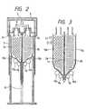
- Figs. 1A to 1Cschematically show a discharge bottle according to a first embodiment of the present invention as one of embodiments in which the flexible vessels are pressed to discharge the contents of the flexible vessels in a manner as described above.
- the discharge bottle 1acomprises, in its side, two tube-like (cylindrical) or pouch-like (in the form of a flat bag obtained by sticking one or two sheets) flexible vessels 2a and 2b, a holding vessel 3 for arranging side by side the flexible vessels 2a and 2b vertically to put the mouth portions 2x and 2y of the flexible vessels 2a and 2b upside, a bottom vessel 4 located under the holding vessel 3 for supporting the holding vessel 3 in an erected state, and a cover 6 provided with a discharge hole 5.
- fitting holes 7a and 7bare formed in the mouth portions 2x and 2y of the flexible vessels 2a and 2b respectively so as to be communicated, through a discharge passage 8, with the discharge hole 5 provided in the cover 6.
- a first pair of roller-like pressing members 9a and 9b and a second pair of roller-like pressing members 10a and 10bare provided in the inside of the bottom vessel 4.
- the first pair of roller-like pressing members 9a and 9bare designed to nip the flexible vessels 2a and 2b arranged side by side in the holding vessel 3 so as to press the flexible vessels intensively whereas the second pair of roller-like pressing members 10a and 10b are designed to press the flexible vessels 2a and 2b more loosely than the first pair of roller-like pressing members 9a and 9b.
- a partition plate 11is disposed between the two flexible vessels 2a and 2b.
- a guide 12is provided for guiding the partition plate 11 so that not only the partition plate 11 can be held vertically but also the two flexible vessels 2a and 2b can be moved vertically.
- the partition plate 11 used hereininclude, for example, a 1-3 mm thick plate of a resin such as polyvinyl chloride, polyethylene, polypropylene, etc., and a 1-3 mm thick plate of a metal such as aluminum, etc.
- Pressing sheets 13a and 13bare respectively disposed between the flexible vessel 2a and the roller-like pressing members 9a and 10a, and between the flexible vessel 2b and the roller-like pressing members 9b and 10b.
- the pressing sheets 13a and 13bfor example, polyethylene sheets each having a thickness of from about 0.5 mm to about 3 mm can be used preferably.
- the pressing sheets 13a and 13bare not limited to sheets of uniform thickness and drainboard-like sheets 13p and 13q may be provided as shown in Fig. 3. In this case, it is preferable to prepare the drainboard-like sheets 13p and 13q in such a manner as follows in order to smoothen the work of pressing the flexible vessels 2a and 2b as will be described later.
- the drainboard-like sheetsare formed of board-like members each of which is made from resin such as polyethylene, or the like, and has a vertical length L1 (Fig. 3) in a range of from about 2 mm to about 20 mm and a thickness in a range of from about 1 mm to about 3 mm.
- the board-like membersare arranged with intervals L2 in a range of about from 1 mm to 2 mm and adjacent ones of the board-like members are connected to each other through a sheet of resin such polyethylene, or the like, having a thickness in a range of from about 0.5 mm to about 2 mm.
- Examples of the flexible vessels arranged side by side in the inside of the holding vessel 3include, for example, tube or pouch vessels each formed from a plastic sheet or a sheet of lamination of a metal thin film and a plastic sheet.
- contents of the flexible vesselsvarious cream or gel matters may be used.
- such contentsmay be used as the first and second agents in a two-agent type hair dye, a two-agent type hair bleach, a two-agent type dentifrice, or the like.
- the cover 6is pressed as indicated by the arrow after the flexible vessels 2a and 2b are contained in the holding vessel 3 and the mouth portions 2x and 2y of the flexible vessels 2a and 2b are fitted to the fitting holes 7a and 7b respectively. As a result, the cover 6 is pressed down as shown in Fig. 2 and, accordingly, the holding vessel 3 is also pressed down.
- the flexible vessels 2a and 2bare inserted into a gap between the first pair of roller-like pressing members 9a and 9b from the lower end portions of the flexible vessels 2a and 2b, so that the first pair of roller-like pressing members 9a and 9b slide relatively toward the mouth portions 2x and 2y of the flexible vessels 2a and 2b. Accordingly, the flexible vessels 2a and 2b are squeezed gradually upward from the lower end portions thereof, so that the contents of the two flexible vessels 2a and 2b are discharged simultaneously through the discharge hole 5 of the cover 6 in accordance with the amount of pressing against the cover 6. Accordingly, in use of such a two-agent type cosmetic, conventional tiresomeness that two flexible vessels must be squeezed individually can be eliminated.
- the pressing operationcan be carried out smoothly because the flexible vessels 2a and 2b are pressed loosely by the second pair of roller-like pressing members 10a and 10b in advance before the flexible vessels 2a and 2b are squeezed by intensive pressing by means of the first pair of roller-like pressing members 9a and 9b.
- the flexible vessels 2a and 2bare not pressed directly by the first pair of roller-like pressing members 9a and 9b but pressed through the pressing sheets 13a and 13b respectively. Accordingly, the pressing operation can be carried out more smoothly. Further, in the case of a pouch formed from a laminate sheet containing an aluminum layer, or the like, as a gas barrier layer, there is a risk that the gas barrier layer may be ruptured in the inside of the laminate sheet correspondingly to the pressing condition when the surface of the pouch is pressed by rollers. By using the pressing sheets 13a and 13b, however, the aforementioned rupture of the gas barrier layer can be prevented. Furthermore, by using drainboard-like sheets 13p and 13q shown in Fig.
- the pressing operationcan be carried out more smoothly and more efficiently because the flexible vessels 2a and 2b can be pressed along the external shape of the drainboard-like sheets 13p and 13q so that the amounts of the contents remaining in the pressed regions of the flexible vessels 2a and 2b can be reduced greatly.
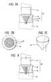
- stopper tensile rings 14can be provided multistageously in the bottom vessel 4. Each of the stopper tensile rings 14 can be removed from the bottom vessel 4 by pulling as indicated by the arrow A.
- stopper projections 15can be provided in the bottom vessel 4.
- Each of the stopper projections 15is designed so that the projection 15 is projected from a side wall surface of the bottom vessel 4 or put into the side wall by sliding as indicated by the arrow.
- stopper pluck rings 16can be provided in the bottom vessel 4.
- Each of the pluck rings 16is designed so that the ring 16 per se can be plucked from the bottom vessel 4 by turning its knob 16a.
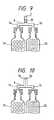
- a check-valvecan be further provided in the discharge passage 8 between the fitting holes 7a and 7b and the discharge hole 5, if necessary.
- check-valve 20various known valves may be used.
- the check-valve 20is constituted by a small-diameter cylindrical member 21, a large-diameter cylindrical member 22, long and short beam-like members 23 formed alternately so as to project from the joint portion of these cylindrical members toward the axial center of the large-diameter cylindrical member 22, and an elastic valve 24 fitted to the small-diameter cylindrical member 21 side of the beam-like members 23.
- ends of the long beam-like members 23are connected to a ring.
- the elastic valve 24substantially has a shape as indicated by the solid line in Fig.
- the elastic valve 24is, however, designed so as to be deformed as indicated by the broken line in Fig. 7C when pressed as indicated by the arrow in Fig. 7C while the elastic valve 24 is restored to its original shape when the pressing is released.
- the check-valve 20is provided in the discharge passage 8 of the discharge bottle 1a in Fig. 1A so that the small-diameter cylindrical member 21 is located in the discharge hole 5 side of the discharge bottle 1a whereas the large-diameter cylindrical member 22 is located in the fitting hole 7a or 7b side
- the content of either of the flexible vessels 2a and 2bpresses the elastic valve 24 and passes through the check-valve 20 as indicated by the arrow in Fig. 8 so as to be discharged through the discharge hole 5 when the flexible vessels 2a and 2b are squeezed from its lower end portions.
- the content discharged from either of the flexible vessels 2a and 2bis prevented from returning to the flexible vessel 2a or 2b. Accordingly, even after the flexible vessels 2a and 2b are attached into the discharge bottle 1a, the contents of the flexible vessels 2a and 2b can be preserved stably.
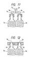
- Fig. 1Ahas shown the case where the contents discharged from the mouth portions 2x and 2y of the two flexible vessels 2a and 2b are brought into contact with each other in the discharge passage 8 of the discharge bottle 1a before reaching the discharge hole 5 of the discharge bottle 1a so that the contents are discharged in a slightly mixed state through the discharge hole 5, if necessary, the invention can be applied to the case where a mixing means 25 is provided in the discharge passage 8 as shown in Fig. 9 so that the contents of the two flexible vessels 2a and 2b are discharged in a sufficiently mixed state through the discharge hole 5.
- the mixing meansfor example, there can be used a means formed by providing helical plates having inclinations reverse to each other with respect to the center of the axis.
- the inventioncan be applied also to the case where the discharge bottle is contrariwise designed so that the contents of the two flexible vessels 2a and 2b are first mixed just before they are discharged through the discharge hole 5.
- the discharge passage 8may be divided into two channels in its inside so that the contents are discharged through adjacent discharge holes 5a and 5b respectively.
- the discharge bottlemay be designed so that the contents of the two flexible vessels 2a and 2b are discharged through discharge holes 5a and 5b of discharge passages 8a and 8b provided quite separately.
- the discharge holes 5a and 5b of the discharge bottlemay be made to serve as fitting holes 7a and 7b for fitting the mouth portions 2x and 2y of the flexible vessels 2a and 2b so that the discharge passage 8 can be omitted.
- the aforementioned embodimenthas been described about the case where, for example, the number of flexible vessels arranged side by side in the holding vessel is two so that the contents of the two flexible vessels are discharged simultaneously
- the inventioncan be applied also to the case where three or more flexible vessels are arranged side by side in the holding vessel, if necessary, so that the contents thereof are discharged simultaneously.
- one discharge holemay be provided in the discharge bottle or a plurality of discharge holes may be provided in the discharge bottle.
- a comb-like coateris preferably attached to the end portion of the discharge hole 5 in the discharge bottle.
- an opening portionis provided between the comb teeth so as to be communicated with the discharge hole 5, so that two agents in the two-agent type hair dye are discharged simultaneously through the opening portion.
- the hair dying operationcan be carried out more simply by using such a coater attached to the discharge bottle according to the present invention.
- two agents in a two-agent type cosmeticsuch as a hair dye, or the like, can be discharged simultaneously in use, so that the convenience in use of the two-agent type cosmetic can be improved greatly.
Landscapes
- Engineering & Computer Science (AREA)
- Mechanical Engineering (AREA)
- Containers And Packaging Bodies Having A Special Means To Remove Contents (AREA)
- Tubes (AREA)
Description
- The present invention relates to a non-aerosol typedischarge bottle from which two cream or gel agents containedin flexible vessels respectively can be dischargedsimultaneously of the type as disclosed in FR-A-265 14 85.
- Said conventional discharge bottle comprises pressing means for pressing liquidmatters out of flexible vessels wherein said pressing means include roller-like pressingmembers disposed below the aforementioned flexible vessels, said flexible vessels beingnipped between and pressed by said roller-like pressing members.
- Heretofore, as a two-agent type cosmetic, there isknown a two-agent type hair dye composed of a first agent,for example, containing oxidation dyes, and a second agent,for example, containing an oxidizer such as hydrogenperoxide, or the like. There is further known a two-agenttype hair bleach composed of a first agent containing analkaline compound, and a second agent containing hydrogenperoxide. Besides hair cosmetics such as hair dye, a hairbleach, etc., there is known a two-agent type dentifricecomposed of a first agent such as calcium carbonate, or thelike, for providing a brushing/cleaning effect, and a secondagent containing hydrogen peroxide for providing a bleachingeffect.
- In the aforementioned two-agent type cosmetic, thefirst and second agents are contained in flexible vesselssuch as plastic tubes, tubes of lamination of metal foil andplastic sheet, etc., individually in view of safety of storage, and the cosmetic can be used after the first andsecond agents are discharged from the respective vessels andmixed with each other.
- However, there arises a problem that it istroublesome to squeeze the first and second agents from theflexible vessels respectively and mix them with each otherwhenever the cosmetic is to be used.
- From EP-A-0124852, there is known a non-aerosol type discharge bottle havingpressing means for pressing flexible vessels to discharge the liquid matters containedtherein. Said pressing means include a screw-like shaft member and a disk-like pressingmember threadedly engaged with said screw-like shaft member.
- Furthermore, there is known from US-A-5,137,178 a non-aerosol type dischargebottle which has pressing means in the form of plate-like pressing members for pressingthe liquid containing flexible vessels.
- It is an object of the present invention to provide a non-aerosol type dischargebottle of the type as indicated in the preamble portion of
claim 1 which is improved withrespect to discharging the contents thereof. - The above object is achieved by the subject matter of
claim 1. - Preferred embodiments and further improvements are defined in depending subclaims.
- Fig. 1A is a schematic sectional view of a dischargebottle according to the presentinvention;
- Fig. 1B is a sectional view taken along the line I-Iin Fig. 1A;
- Fig. 1C is a top view from the arrow I' in Fig. 1A;
- Fig. 2 is a sectional view for explaining theoperation of the discharge bottle according tothe present invention;
- Fig. 3 is a sectional view of a pressing sheet usedin the discharge bottle according to thepresent invention;
- Fig. 4A is a perspective view of a stopper tensile-ring-includingbottom vessel used in the discharge bottleaccording to the present invention;
- Fig. 4B is a sectional view taken along the line IV-IVin Fig. 4A;
- Fig. 5A is a perspective view of a stopperprojection-including bottom vessel used in the dischargebottle according to the present invention;
- Fig. 5B is a sectional view taken along the line V-Vin Fig. 5A;
- Fig. 6A is a perspective view of a stopper pluck-ring-includingbottom vessel used in, the discharge bottleaccording to the present invention;
- Fig. 6B is a sectional view taken along the line VI-VIin Fig. 6A;
- Fig. 7A is a side view of a check-valve used in thedischarge bottle according to thepresent invention;
- Fig. 7B is a bottom view of the check-valve;
- Fig. 7C is a view for explaining an elastic valveacting as the check-valve;
- Fig. 8 is a view for explaining the operation of thecheck-valve used in the discharge bottle according tothe present invention;
- Fig. 9 is a view for explaining a first modificationof the neighborhood of the discharge hole in the dischargebottle according to the presentinvention;
- Fig. 10 is a view for explaining a secondmodification of the neighborhood of the discharge hole in thedischarge bottle according to thepresent invention;
- Fig. 11 is a view for explaining a third modification of the neighborhood of the discharge hole in the dischargebottle according to the presentinvention;
- Fig. 12 is a view for explaining a fourthmodification of the neighborhood of the discharge hole in thedischarge bottle according to thepresent invention;
- An Embodiment of the present invention will bedescribed below with reference to the drawings. In thedrawings, the same as or equivalent to each other arereferenced correspondingly.
- The discharge bottle according to the presentinvention is designed so that a plurality of flexible vesselsrespectively containing cream or gel matters different fromeach other are arranged side by side by a holding vessel andthe contents of the flexible vessels are dischargedsimultaneously by pressing the flexible vessels. As specificembodiments for pressing the flexible vessels, variousembodiments may be used so long as the contents of theplurality of flexible vessels can be discharged from theflexible vessels simultaneously.
- For example, as embodiments for pressing the flexiblevessels, there are used an embodiment in which the contentsof the flexible vessels are extruded by pressing the flexiblevessels linearly or zonally at end portions opposite to themouth portions of the flexible vessels so as to cross the body portions of the flexible vessels and by sliding the linearlyor zonally pressed portions relatively toward the mouthportions of the flexible vessels, an embodiment in which sidesurfaces of the flexible vessels are face-pushed, etc. Figs.1A to 1C schematically show a discharge bottle according to afirst embodiment of the present invention as one ofembodiments in which the flexible vessels are pressed todischarge the contents of the flexible vessels in a manner asdescribed above.
- According to the invention, the
discharge bottle 1acomprises, in its side, two tube-like (cylindrical) or pouch-like(in the form of a flat bag obtained by sticking one ortwo sheets)flexible vessels holding vessel 3for arranging side by side theflexible vessels mouth portions flexible vessels bottom vessel 4 locatedunder theholding vessel 3 for supporting theholding vessel 3 in an erected state, and acover 6 provided with adischarge hole 5. - In the inside of the
cover 6, fittingholes mouth portions flexiblevessels discharge passage 8, with thedischarge hole 5provided in thecover 6. - In the inside of the
bottom vessel 4, a first pair ofroller-like pressingmembers members members flexible vessels holding vessel 3 so as to press the flexiblevessels intensively whereas the second pair of roller-likepressingmembers flexible vessels members - In the
holding vessel 3, apartition plate 11 isdisposed between the twoflexible vessels bottom vessel 4, aguide 12 is provided for guiding thepartition plate 11 so that not only thepartition plate 11can be held vertically but also the twoflexible vessels partitionplate 11 used herein include, for example, a 1-3 mm thickplate of a resin such as polyvinyl chloride, polyethylene,polypropylene, etc., and a 1-3 mm thick plate of a metal suchas aluminum, etc. Pressing sheets flexible vessel 2a and the roller-like pressingmembers flexible vessel 2b andthe roller-like pressingmembers pressingsheets pressing sheets like sheets 13p and 13q may be provided as shown in Fig. 3. Inthis case, it is preferable to prepare the drainboard-likesheets 13p and 13q in such a manner as follows in order tosmoothen the work of pressing theflexible vessels - Examples of the flexible vessels arranged side byside in the inside of the holding
vessel 3 include, forexample, tube or pouch vessels each formed from a plasticsheet or a sheet of lamination of a metal thin film and aplastic sheet. As the contents of the flexible vessels,various cream or gel matters may be used. For example, suchcontents may be used as the first and second agents in a two-agenttype hair dye, a two-agent type hair bleach, a two-agenttype dentifrice, or the like. - In use of the
discharge bottle 1a, as shown in Fig.1A, thecover 6 is pressed as indicated by the arrow aftertheflexible vessels vessel 3 and themouth portions flexiblevessels fitting holes cover 6 is pressed down asshown in Fig. 2 and, accordingly, the holdingvessel 3 isalso pressed down. As a result, theflexible vessels pressing members flexible vessels pressing members mouth portions flexible vessels flexible vessels flexible vessels dischargehole 5 of thecover 6 in accordance with the amount ofpressing against thecover 6. Accordingly, in use of such atwo-agent type cosmetic, conventional tiresomeness that twoflexible vessels must be squeezed individually can beeliminated. - By providingthe second pair of roller-like
pressing members flexible vessels pressing members flexiblevessels pressing members - Furthermore, in the discharge bottle according to theinvention, the
flexible vessels pressingmembers pressing sheets pressing sheets like sheets 13pand 13q shown in Fig. 3 as the pressing sheets, the pressingoperation can be carried out more smoothly and moreefficiently because theflexible vessels likesheets 13p and 13q so that the amounts of the contentsremaining in the pressed regions of theflexible vessels - When the
cover 6 is pressed down to discharge the contents of the twoflexible vessels discharge hole 5 as described above, the amountsof the discharged contents are preferably controlled bypressing down thecover 6 gradually by predetermined amounts.Specifically, for example, as shown in Figs. 4A and 4B,stopper tensile rings 14 can be provided multistageously inthebottom vessel 4. Each of the stopper tensile rings 14can be removed from thebottom vessel 4 by pulling asindicated by the arrow A. Alternatively, as show in Figs. 5Aand 5B,stopper projections 15 can be provided in thebottomvessel 4. Each of thestopper projections 15 is designed sothat theprojection 15 is projected from a side wall surfaceof thebottom vessel 4 or put into the side wall by slidingas indicated by the arrow. Alternatively, as show in Figs.6A and 6B, stopper pluckrings 16 can be provided in thebottom vessel 4. Each of the pluck rings 16 is designed sothat thering 16 per se can be plucked from thebottom vessel 4 by turning its knob 16a. - In the
discharge bottle 1a, a check-valve can befurther provided in thedischarge passage 8 between thefitting holes discharge hole 5, ifnecessary. - As the check-valve, various known valves may be used.For example, such a check-
valve 20 as shown in Figs. 7A and7B may be used. The check-valve 20 is constituted by asmall-diametercylindrical member 21, a large-diametercylindrical member 22, long and short beam-like members 23formed alternately so as to project from the joint portion ofthese cylindrical members toward the axial center of thelarge-diametercylindrical member 22, and anelastic valve 24fitted to the small-diametercylindrical member 21 side ofthe beam-like members 23. Here, ends of the long beam-likemembers 23 are connected to a ring. Further, theelasticvalve 24 substantially has a shape as indicated by the solidline in Fig. 7C and is fitted to the small-diametercylindrical member 21 side of the beam-like members 23. Theelastic valve 24 is, however, designed so as to be deformedas indicated by the broken line in Fig. 7C when pressed asindicated by the arrow in Fig. 7C while theelastic valve 24is restored to its original shape when the pressing isreleased. - Accordingly, in the case where the check-
valve 20 isprovided in thedischarge passage 8 of thedischarge bottle 1a in Fig. 1A so that the small-diametercylindrical member 21 is located in thedischarge hole 5 side of thedischargebottle 1a whereas the large-diametercylindrical member 22 islocated in thefitting hole flexible vessels elasticvalve 24 and passes through the check-valve 20 as indicatedby the arrow in Fig. 8 so as to be discharged through thedischarge hole 5 when theflexible vessels flexible vessels flexible vessel flexible vessels discharge bottle 1a, the contents oftheflexible vessels - The aforementioned embodiment of the discharge bottlein which the flexible vessels are pressed by using theroller-like pressing members can be modified variously.
- Although Fig. 1A has shown the case where thecontents discharged from the
mouth portions flexible vessels discharge passage 8 of thedischarge bottle 1a before reaching thedischarge hole 5 of thedischargebottle 1a so that the contents are discharged in a slightlymixed state through thedischarge hole 5, if necessary, theinvention can be applied to the case where a mixing means 25is provided in thedischarge passage 8 as shown in Fig. 9 sothat the contents of the twoflexible vessels discharge hole 5. As the mixing means, for example, therecan be used a means formed by providing helical plates havinginclinations reverse to each other with respect to the centerof the axis. - The invention can be applied also to the case wherethe discharge bottle is contrariwise designed so that thecontents of the two
flexible vessels dischargehole 5. In this case, for example, as shown in Fig. 10, thedischarge passage 8 may be divided into two channels in itsinside so that the contents are discharged throughadjacentdischarge holes flexible vessels discharge holes dischargepassages fitting holes mouth portions flexiblevessels discharge passage 8 can beomitted. - Although the aforementionedembodiment has been described about the case where, forexample, the number of flexible vessels arranged side by sidein the holding vessel is two so that the contents of the twoflexible vessels are discharged simultaneously, the inventioncan be applied also to the case where three or more flexiblevessels are arranged side by side in the holding vessel, ifnecessary, so that the contents thereof are discharged simultaneously. In this case, one discharge hole may beprovided in the discharge bottle or a plurality of dischargeholes may be provided in the discharge bottle.
- Various coatersmay be attached to the end of the discharge hole inthe discharge bottle according to the present invention, ifnecessary. For example, in the case where flexible vesselsfor a two-agent type hair dye are put in the discharge bottleaccording to the present invention, a comb-like coater ispreferably attached to the end portion of the
discharge hole 5 in the discharge bottle. In the comb-likecoater, an opening portion is provided between thecomb teeth so as to be communicated with thedischargehole 5, so that two agents in the two-agent type hair dye aredischarged simultaneously through the opening portion.The hair dying operation can be carried out more simply byusing such a coater attached to the discharge bottleaccording to the present invention. - According to the present invention, two agents in atwo-agent type cosmetic such as a hair dye, or the like, canbe discharged simultaneously in use, so that the conveniencein use of the two-agent type cosmetic can be improvedgreatly.
Claims (3)
- A non-aerosol type discharge bottle comprising:characterised in thata plurality of flexible vessels (2a,2b) respectivelycontaining liquid matters different from each other and selectedfrom the group consisting of cream and gel matters;a holding vessel (3) in which said plurality of vessels arearranged vertically side by side so that the mouth portions(2x,2y) of said flexible vessels are put upside;at least one discharge hole (5) for discharging said liquidmatters, anda pressing means for pressing said flexible vessels todischarge said liquid matters from said flexible vessels throughsaid discharge hole,
said pressing means includes a first pair (9a,9b) of roller-likepressing members for pressing said flexible vessels (2a,2b)intensively and a second pair of roller-like pressing members(10a,10b) disposed in positions nearer said mouth portions(2x,2y) of said flexible vessels than said first pair of said roller-likepressing members and for pressing said flexible vesselsmore loosely than said first pair of roller-like pressing members. - A discharge bottle according to claim 1, wherein said flexiblevessels (2a,2b) are nipped between and pressed by said roller-likepressing members so that the roller-like pressing members(9a,9b;10a,10b) move relatively toward said mouth portions(2x,2y) when said holding vessel is pressed down toward saidroller-like pressing members.
- A discharge bottle according to claim 2, wherein each of said flexiblevessels (2a,2b) includes a sheet (13a,13b,13p,13q) through which saidroller-like pressing members (9a,9b;10a,10b) press said flexible vessels.
Applications Claiming Priority (3)
| Application Number | Priority Date | Filing Date | Title |
|---|---|---|---|
| JP38966/96 | 1996-01-31 | ||
| JP08038966AJP3077135B2 (en) | 1996-01-31 | 1996-01-31 | Discharge container |
| JP3896696 | 1996-01-31 |
Publications (3)
| Publication Number | Publication Date |
|---|---|
| EP0792820A2 EP0792820A2 (en) | 1997-09-03 |
| EP0792820A3 EP0792820A3 (en) | 1997-12-03 |
| EP0792820B1true EP0792820B1 (en) | 2002-05-02 |
Family
ID=12539911
Family Applications (1)
| Application Number | Title | Priority Date | Filing Date |
|---|---|---|---|
| EP97101566AExpired - LifetimeEP0792820B1 (en) | 1996-01-31 | 1997-01-31 | Discharge bottle for jetting two agents simultaneously |
Country Status (4)
| Country | Link |
|---|---|
| US (1) | US5848730A (en) |
| EP (1) | EP0792820B1 (en) |
| JP (1) | JP3077135B2 (en) |
| DE (1) | DE69712248T2 (en) |
Families Citing this family (81)
| Publication number | Priority date | Publication date | Assignee | Title |
|---|---|---|---|---|
| US6783514B2 (en)* | 1997-01-31 | 2004-08-31 | United States Surgical Corporation | Fibrin sealant applicator |
| JPH11199454A (en)* | 1998-01-08 | 1999-07-27 | Yamahatsu Sangyo Kk | Two-pack type oxidation hair dye and two-pack type decoloring agent |
| ATA49899A (en)* | 1999-03-19 | 2002-06-15 | Immuno Ag | METHOD AND DEVICE FOR MIXING COMPONENTS |
| US6250346B1 (en)* | 1999-05-28 | 2001-06-26 | James Anzai Castillo | Device for maintaining separate ingredients in liquid food products |
| JP4043666B2 (en)* | 1999-09-27 | 2008-02-06 | 前田建設工業株式会社 | Kneading nozzle |
| US6648641B1 (en)* | 2000-11-22 | 2003-11-18 | The Procter & Gamble Company | Apparatus, method and product for treating teeth |
| US6454133B1 (en)* | 2001-05-03 | 2002-09-24 | Kenneth Oscar Lopez | Toothpaste butler |
| NL1018232C2 (en)* | 2001-06-07 | 2002-12-10 | Intercon Holland B V | Assembly of frame and packing containing viscous material involves packing formed at least partly from foil material provided with first and second opposing outer ends |
| FR2826641B1 (en) | 2001-06-29 | 2003-09-05 | Oreal | DEVICE FOR THE SIMULTANEOUS DISPENSING OF TWO SEPARATELY PACKAGED PRODUCTS |
| DE10207763A1 (en)* | 2002-02-23 | 2003-09-04 | Fischer Artur Werke Gmbh | Multi-component cartridge has cross sectional surface of each container constant over its length with regard to shape and size, and cross sectional surfaces of containers make up cross sectional surface of cartridge |
| DE10315550A1 (en)* | 2003-04-05 | 2004-10-14 | Wella Ag | Applicator for applying an oxidative hair color |
| US8153108B2 (en)* | 2003-04-25 | 2012-04-10 | Kao Corporation | Hair cosmetic product |
| DE10321322A1 (en)* | 2003-05-13 | 2004-12-02 | Hilti Ag | System with squeezing device and storage container |
| EP1669139B1 (en)* | 2003-10-03 | 2012-03-07 | Kao Corporation | Discharge device |
| HRP20030802A2 (en)* | 2003-10-03 | 2005-04-30 | Vrus-Pervan Iris | Precise hair colouring implement to form frosted and streaky hair and the method for protecting uncoloured hair |
| DE102005021076A1 (en)* | 2005-05-06 | 2006-11-09 | Fischerwerke Artur Fischer Gmbh & Co. Kg | Mixer cartridge for polyurethane foam components has static mixer with back-flow prevention valve |
| JP2007297108A (en)* | 2006-05-01 | 2007-11-15 | Hoyu Co Ltd | Set of tube container |
| JP2008056348A (en)* | 2006-08-04 | 2008-03-13 | Kao Corp | Application container |
| CN101522070A (en)* | 2006-10-09 | 2009-09-02 | 宝洁公司 | Hair treatment application system comprising an absorbent matrix |
| EP1958532A3 (en)* | 2006-10-09 | 2013-06-05 | The Procter and Gamble Company | Hair treatment application system |
| ATE505969T1 (en)* | 2006-10-09 | 2011-05-15 | Procter & Gamble | HAIR STRAINING APPLICATOR AND METHOD |
| US8573232B2 (en) | 2006-10-09 | 2013-11-05 | The Procter & Gamble Company | Hair treatment application system comprising an absorbent substrate |
| WO2008044198A1 (en)* | 2006-10-09 | 2008-04-17 | The Procter & Gamble Company | Hair treatment application system |
| US20080083420A1 (en)* | 2006-10-09 | 2008-04-10 | The Procter & Gamble Company | Hair treatment application system |
| EP1911368A1 (en)* | 2006-10-09 | 2008-04-16 | The Procter and Gamble Company | Hair treatment application system comprising an absorbent substrate |
| CN200988015Y (en)* | 2006-10-30 | 2007-12-12 | 埃森·费尔索夫 | sprayer |
| US7896567B2 (en)* | 2006-11-21 | 2011-03-01 | The Procter & Gamble Company | Dispensing toothbrush |
| JP4684212B2 (en)* | 2006-11-24 | 2011-05-18 | 日本キム株式会社 | Contained matter extraction device and container pressing device used therefor |
| US8136700B2 (en)* | 2007-02-23 | 2012-03-20 | Sealed Air Corporation (Us) | Dual chambered fluid dispenser with mixing chamber |
| EP1969961B1 (en) | 2007-03-13 | 2014-07-23 | The Procter and Gamble Company | A tool for separating a hair bundle |
| US20080267005A1 (en)* | 2007-04-24 | 2008-10-30 | Tyco Healthcare Group Lp | Applicator system and method of use |
| JP5676841B2 (en) | 2007-04-27 | 2015-02-25 | 花王株式会社 | Two-component hair dyeing or decoloring hair cosmetics |
| BRPI0809207B1 (en)* | 2007-04-27 | 2022-04-12 | Kao Corporation | Method for coloring or bleaching hair |
| MX2009013697A (en) | 2007-06-15 | 2010-04-07 | Procter & Gamble | A system for highlighting hair. |
| EP2002751B1 (en) | 2007-06-15 | 2014-05-28 | The Procter and Gamble Company | Device for the application of a hair treatment composition to a hair bundle |
| AU2008263457B2 (en)* | 2007-06-15 | 2012-05-17 | Noxell Corporation | Applicator for a hair treatment composition |
| CN101677665B (en)* | 2007-06-15 | 2013-07-10 | 宝洁公司 | Hair treatment applicator for providing hair strand effects |
| CA2691347C (en) | 2007-06-15 | 2012-10-16 | The Procter & Gamble Company | Applicator for applying a hair treatment composition to a bundle of hair strands |
| CN101801337B (en)* | 2007-10-24 | 2013-04-24 | 花王株式会社 | hair coloring method |
| US8152858B2 (en)* | 2007-10-24 | 2012-04-10 | Kao Corporation | Head hair dyeing method |
| EP2070833B1 (en)* | 2007-12-14 | 2011-02-23 | The Procter & Gamble Company | Container with a device to prevent clogging of a dispensing device of the container |
| EP2196104B1 (en)* | 2008-12-10 | 2018-10-17 | Noxell Corporation | Applicator of a hair treatment composition for improved hair strand effects |
| EP2198739B1 (en)* | 2008-12-10 | 2016-06-01 | The Procter and Gamble Company | Applicator for improved application of a hair treatment composition to a bundle of hair strands |
| EP2198738B1 (en)* | 2008-12-10 | 2018-09-05 | Noxell Corporation | Hair treatment applicator for improved hair strand effects |
| HRP20090094A2 (en)* | 2009-02-16 | 2011-03-31 | Vrus Pervan Iris | Set for precise hair dyeing with hair clamp |
| JP5630989B2 (en) | 2009-03-11 | 2014-11-26 | 花王株式会社 | Two-component hair dye |
| IT1398961B1 (en)* | 2010-03-24 | 2013-03-28 | Piazza S R L | BOTTLE FOR ADMINISTRATIVE CONTEXT OF AT LEAST TWO LIQUID DRUGS. |
| DE202010011715U1 (en)* | 2010-08-23 | 2011-09-23 | Anton Brugger | Dispensers |
| US8636812B2 (en) | 2010-08-31 | 2014-01-28 | Kao Corporation | Two-part foam hair dye |
| JP5485109B2 (en)* | 2010-10-29 | 2014-05-07 | 株式会社吉野工業所 | Double tube feeding device |
| JP5490660B2 (en)* | 2010-10-29 | 2014-05-14 | 株式会社吉野工業所 | Double tube extrusion equipment |
| USD743623S1 (en) | 2010-12-30 | 2015-11-17 | Asako Ishii | Hair coloring device |
| US8596498B2 (en)* | 2011-05-02 | 2013-12-03 | Mouse Trap Design, Llc | Mixing and dispensing device |
| US20140202486A1 (en)* | 2012-02-13 | 2014-07-24 | Jasmine Klapia | Multicolored applicator for eyelashes; three-in-one lip liner, lipstick and lip gloss; nail polish; and multicolored hair applicator |
| EP2865610B1 (en)* | 2012-06-22 | 2020-12-30 | Hoyu Co., Ltd. | Double-aerosol device |
| CH707491A2 (en)* | 2013-01-31 | 2014-07-31 | Christian Rieder | Applicator cartridge in hair product. |
| KR101420128B1 (en)* | 2013-06-17 | 2014-07-17 | (주)연우 | Cosmetic vessel having mixed two-type materials |
| US9527106B2 (en)* | 2013-10-31 | 2016-12-27 | Nordson Corporation | Applicator and method for dispensing a viscous fluid |
| US20150122837A1 (en) | 2013-11-07 | 2015-05-07 | Mouse Trap Design, Llc | Mixing and dispensing device |
| CA2949969C (en)* | 2014-05-23 | 2022-12-20 | Eb Technologies, Llc | Hair coloring variegation device and method of use |
| US10435831B1 (en)* | 2014-07-15 | 2019-10-08 | Rita Harry-Ogiste | Fabric treating accessories and associated use thereof |
| FR3026622B1 (en)* | 2014-10-07 | 2016-12-30 | Laboratoires M&L | SYSTEM FOR MANUFACTURING A COSMETIC PRODUCT BY MIXING FROM SINGLE PACKAGING UNITS. |
| JP6604108B2 (en)* | 2015-09-16 | 2019-11-13 | 株式会社スリーボンド | Viscous material supply apparatus and viscous material supply method |
| CN108697221B (en)* | 2016-01-25 | 2021-05-14 | 欧莱雅 | Filling assembly for manufacturing a dual content packaging and dispensing device |
| FR3067915B1 (en)* | 2017-06-23 | 2021-07-23 | Laboratoires M&L | COUPLE OF CAPSULES ASSEMBLED TOGETHER AND RESPECTIVELY INCLUDING TWO DIFFERENT PHASES TO BE MIXED |
| US11278099B2 (en) | 2017-09-29 | 2022-03-22 | L'oreal | Formula delivery appliance |
| US11291284B2 (en) | 2017-09-29 | 2022-04-05 | L'oreal | Formula delivery head |
| US10569936B1 (en)* | 2018-07-02 | 2020-02-25 | Ray Small | Multi-compartmental container |
| FR3090400B1 (en) | 2018-12-21 | 2023-03-31 | Seb Sa | Manufacturing apparatus, mixing machine and/or receiving device for manufacturing a composition from a mixture of formulations |
| FR3090396B1 (en)* | 2018-12-21 | 2023-03-31 | Seb Sa | Manufacturing apparatus, mixing machine and/or receiving device for manufacturing a composition from a mixture of formulations |
| FR3090397B1 (en)* | 2018-12-21 | 2021-09-17 | Seb Sa | Manufacturing apparatus, mixing machine and / or receiving device for the manufacture of a composition from a mixture of formulations |
| FR3090408B1 (en) | 2018-12-21 | 2023-03-31 | Seb Sa | Manufacturing apparatus, mixing machine and/or receiving device for manufacturing a composition from a mixture of formulations |
| FR3090407B1 (en) | 2018-12-21 | 2020-12-04 | Seb Sa | Manufacturing apparatus, mixing machine and / or receiving device for the manufacture of a composition from a mixture of formulations |
| FR3090403B1 (en) | 2018-12-21 | 2023-03-31 | Seb Sa | Manufacturing apparatus, mixing machine and/or receiving device for manufacturing a composition from a mixture of formulations |
| FR3090401B1 (en) | 2018-12-21 | 2023-04-28 | Seb Sa | Manufacturing apparatus, mixing machine and/or receiving device for manufacturing a composition from a mixture of formulations |
| FR3090402B1 (en)* | 2018-12-21 | 2021-09-17 | Seb Sa | Manufacturing apparatus, mixing machine and / or receiving device for the manufacture of a composition from a mixture of formulations |
| FR3090398B1 (en) | 2018-12-21 | 2021-06-25 | Seb Sa | Manufacturing apparatus, mixing machine and / or receiving device for the manufacture of a composition from a mixture of formulations |
| FR3090404B1 (en) | 2018-12-21 | 2023-03-31 | Seb Sa | Manufacturing apparatus, mixing machine and/or receiving device for manufacturing a composition from a mixture of formulations |
| FR3090405B1 (en) | 2018-12-21 | 2023-04-28 | Seb Sa | Manufacturing apparatus, mixing machine and/or receiving device for manufacturing a composition from a mixture of formulations |
| FR3090406B1 (en) | 2018-12-21 | 2020-12-04 | Seb Sa | Manufacturing apparatus, mixing machine and / or receiving device for the manufacture of a composition from a mixture of formulations |
| EP3777603A1 (en)* | 2019-08-14 | 2021-02-17 | Sulzer Mixpac AG | Dispenser, comb, housing and method of using the dispenser |
Family Cites Families (30)
| Publication number | Priority date | Publication date | Assignee | Title |
|---|---|---|---|---|
| DE215509C (en)* | ||||
| US1823206A (en)* | 1929-03-14 | 1931-09-15 | Charles A Maher | Container for paste tubes |
| US1989713A (en)* | 1930-09-26 | 1935-02-05 | Warren R Smith | Dispensing device |
| US2496004A (en)* | 1945-11-19 | 1950-01-31 | Catherine M Geyer | Paste dispenser |
| DE814723C (en)* | 1949-06-04 | 1951-09-24 | Gottlieb Kozik | Device for the controlled emptying of tubes |
| US2655289A (en)* | 1950-12-22 | 1953-10-13 | Peal J Floyd | Sanitary cream dispenser |
| US2819723A (en)* | 1955-05-31 | 1958-01-14 | Jean Leclabart | Hair dyeing apparatus |
| US3187951A (en)* | 1963-10-04 | 1965-06-08 | H V Hardman Co Inc | Caulking gun |
| US3263862A (en)* | 1965-03-15 | 1966-08-02 | Tazzeo James Phillip | Dispensing containers for collapsible tubes |
| DE1486405A1 (en)* | 1965-04-15 | 1969-06-04 | H V Hardman Company Inc | Device for mixing and dispensing materials |
| FR1468507A (en)* | 1966-02-17 | 1967-02-03 | Bostik Sa | Container intended in particular for use in putty guns |
| FR1591250A (en)* | 1968-11-05 | 1970-04-27 | ||
| US3866800A (en)* | 1969-02-12 | 1975-02-18 | Alberto Culver Co | Non-pressurized package containing self-heating products |
| JPS5480444U (en)* | 1977-11-15 | 1979-06-07 | ||
| DE3316922A1 (en)* | 1983-05-09 | 1984-11-15 | Henkel KGaA, 4000 Düsseldorf | DEVICE FOR DELIVERING SUBSTANCES TO BE MIXED IN A PRESENT RATIO |
| GB2174356A (en)* | 1985-05-03 | 1986-11-05 | Albyn Of Stonehaven Limited | Container with closure and spreader |
| JPS6326547U (en)* | 1986-08-01 | 1988-02-22 | ||
| FR2603558B1 (en)* | 1986-09-04 | 1988-11-18 | Oreal | DISPENSING HEAD OF A PASTY PRODUCT RESULTING FROM THE MIXTURE OF TWO SEPARATELY STORED COMPONENTS AND PACKAGING ASSEMBLY WITH SUCH A DISPENSING HEAD |
| JPH0734839Y2 (en)* | 1989-02-28 | 1995-08-09 | ぺんてる株式会社 | Discharge container |
| DE8912515U1 (en)* | 1989-03-24 | 1990-02-15 | Franz Pohl, Metall- und Kunststoffwarenfabrik GmbH, 7500 Karlsruhe | Donors |
| FR2651485A1 (en)* | 1989-09-05 | 1991-03-08 | Lir France Sa | Device for packaging and dispensing two pasty products or products of similar consistency |
| US4998645A (en)* | 1990-01-02 | 1991-03-12 | John Pearson | Apparatus for dispensing the contents of a tube |
| JP3043040B2 (en)* | 1990-08-20 | 2000-05-22 | 沖電気工業株式会社 | Image binarization method |
| DE9101080U1 (en)* | 1991-01-31 | 1991-04-18 | Rudi Becker GmbH, 7507 Pfinztal | Device for squeezing tubes |
| US5137178A (en)* | 1991-04-17 | 1992-08-11 | Elizabeth Arden Company. Division Of Conopco, Inc. | Dual tube dispenser |
| JPH0546751U (en)* | 1991-11-22 | 1993-06-22 | シャープ化学工業株式会社 | Squeezing gun for two tubes |
| JP3004811B2 (en)* | 1992-06-02 | 2000-01-31 | 株式会社吉野工業所 | Creamy container |
| US5332124A (en)* | 1993-05-17 | 1994-07-26 | Chesebrough-Pond's, Usa Co., A Division Of Conopco, Inc. | Multi-cavity dispensing refill cartridge |
| JPH0722951U (en)* | 1993-09-29 | 1995-04-25 | 花王株式会社 | Pouring container |
| US5699935A (en)* | 1996-01-18 | 1997-12-23 | The Procter & Gamble Company | Inverting bag co-dispenser |
- 1996
- 1996-01-31JPJP08038966Apatent/JP3077135B2/ennot_activeExpired - Fee Related
- 1997
- 1997-01-30USUS08/790,997patent/US5848730A/ennot_activeExpired - Lifetime
- 1997-01-31EPEP97101566Apatent/EP0792820B1/ennot_activeExpired - Lifetime
- 1997-01-31DEDE69712248Tpatent/DE69712248T2/ennot_activeExpired - Lifetime
Also Published As
| Publication number | Publication date |
|---|---|
| JP3077135B2 (en) | 2000-08-14 |
| JPH09207952A (en) | 1997-08-12 |
| DE69712248D1 (en) | 2002-06-06 |
| US5848730A (en) | 1998-12-15 |
| DE69712248T2 (en) | 2002-08-22 |
| EP0792820A2 (en) | 1997-09-03 |
| EP0792820A3 (en) | 1997-12-03 |
Similar Documents
| Publication | Publication Date | Title |
|---|---|---|
| EP0792820B1 (en) | Discharge bottle for jetting two agents simultaneously | |
| EP0271976B1 (en) | Asymmetric stress concentrator for a dispenser package | |
| US5373966A (en) | Single use dispensing sachets and method of and means for manufacture of same | |
| US5335827A (en) | Multi-cavity dispensing refill cartridge | |
| US5137178A (en) | Dual tube dispenser | |
| AU669711B2 (en) | Multi-cavity dispensing refill cartridge | |
| EP0675834B1 (en) | Multi-outlet fluid dispenser pouch | |
| US6641319B2 (en) | Dispenser and process | |
| US6234190B1 (en) | Mixing adaptor with rupturable membrane | |
| EP3259199B1 (en) | Multi chamber delivery system | |
| US20020036212A1 (en) | Dispensing device and methods | |
| IE57017B1 (en) | Dispenser package | |
| IL104997A (en) | Stress concentrator aperture-forming means for sealed containers and packages | |
| GB1588406A (en) | Ointment container | |
| JP2004515424A (en) | Package and dispense actuator for multi-component compositions | |
| KR20170128708A (en) | Mask-pack pouch | |
| EP0675839B1 (en) | Refillable multi-cavity dispenser and refill cartridge therefor | |
| HK1002858A (en) | Discharge bottle for jetting two agents simultaneously | |
| US20130255708A1 (en) | Device, system and method for applying at least one application agent to hair | |
| JP2000007000A (en) | Discharge container | |
| JP2002255250A (en) | Flexible multi-chamber container and holder housing the same | |
| JP2002255201A (en) | Flexible container | |
| GB2322114A (en) | Pouches for dispensing two-part reactive chemicals | |
| JP2000109145A (en) | Discharge container | |
| JPH10129682A (en) | Separate storage type container for multicomponent |
Legal Events
| Date | Code | Title | Description |
|---|---|---|---|
| PUAI | Public reference made under article 153(3) epc to a published international application that has entered the european phase | Free format text:ORIGINAL CODE: 0009012 | |
| AK | Designated contracting states | Kind code of ref document:A2 Designated state(s):DE GB | |
| PUAL | Search report despatched | Free format text:ORIGINAL CODE: 0009013 | |
| AK | Designated contracting states | Kind code of ref document:A3 Designated state(s):DE GB | |
| 17P | Request for examination filed | Effective date:19980306 | |
| 17Q | First examination report despatched | Effective date:20000725 | |
| GRAG | Despatch of communication of intention to grant | Free format text:ORIGINAL CODE: EPIDOS AGRA | |
| GRAG | Despatch of communication of intention to grant | Free format text:ORIGINAL CODE: EPIDOS AGRA | |
| GRAH | Despatch of communication of intention to grant a patent | Free format text:ORIGINAL CODE: EPIDOS IGRA | |
| REG | Reference to a national code | Ref country code:GB Ref legal event code:IF02 | |
| GRAH | Despatch of communication of intention to grant a patent | Free format text:ORIGINAL CODE: EPIDOS IGRA | |
| GRAA | (expected) grant | Free format text:ORIGINAL CODE: 0009210 | |
| AK | Designated contracting states | Kind code of ref document:B1 Designated state(s):DE GB | |
| REG | Reference to a national code | Ref country code:GB Ref legal event code:FG4D | |
| REF | Corresponds to: | Ref document number:69712248 Country of ref document:DE Date of ref document:20020606 | |
| PLBE | No opposition filed within time limit | Free format text:ORIGINAL CODE: 0009261 | |
| STAA | Information on the status of an ep patent application or granted ep patent | Free format text:STATUS: NO OPPOSITION FILED WITHIN TIME LIMIT | |
| 26N | No opposition filed | Effective date:20030204 | |
| REG | Reference to a national code | Ref country code:HK Ref legal event code:WD Ref document number:1002858 Country of ref document:HK | |
| PGFP | Annual fee paid to national office [announced via postgrant information from national office to epo] | Ref country code:DE Payment date:20130123 Year of fee payment:17 Ref country code:GB Payment date:20130130 Year of fee payment:17 | |
| REG | Reference to a national code | Ref country code:DE Ref legal event code:R119 Ref document number:69712248 Country of ref document:DE | |
| GBPC | Gb: european patent ceased through non-payment of renewal fee | Effective date:20140131 | |
| REG | Reference to a national code | Ref country code:DE Ref legal event code:R119 Ref document number:69712248 Country of ref document:DE Effective date:20140801 | |
| PG25 | Lapsed in a contracting state [announced via postgrant information from national office to epo] | Ref country code:DE Free format text:LAPSE BECAUSE OF NON-PAYMENT OF DUE FEES Effective date:20140801 | |
| PG25 | Lapsed in a contracting state [announced via postgrant information from national office to epo] | Ref country code:GB Free format text:LAPSE BECAUSE OF NON-PAYMENT OF DUE FEES Effective date:20140131 |