EP0792055B1 - A radio telephone - Google Patents
A radio telephoneDownload PDFInfo
- Publication number
- EP0792055B1 EP0792055B1EP97301133AEP97301133AEP0792055B1EP 0792055 B1EP0792055 B1EP 0792055B1EP 97301133 AEP97301133 AEP 97301133AEP 97301133 AEP97301133 AEP 97301133AEP 0792055 B1EP0792055 B1EP 0792055B1
- Authority
- EP
- European Patent Office
- Prior art keywords
- cover
- telephone
- housing
- radio telephone
- conductors
- Prior art date
- Legal status (The legal status is an assumption and is not a legal conclusion. Google has not performed a legal analysis and makes no representation as to the accuracy of the status listed.)
- Expired - Lifetime
Links
- 239000004020conductorSubstances0.000claimsdescription15
- 238000006073displacement reactionMethods0.000claimsdescription5
- 230000005489elastic deformationEffects0.000claimsdescription2
- 230000008878couplingEffects0.000claims3
- 238000010168coupling processMethods0.000claims3
- 238000005859coupling reactionMethods0.000claims3
- 239000004033plasticSubstances0.000description7
- 229920003023plasticPolymers0.000description7
- 239000000853adhesiveSubstances0.000description3
- 230000001070adhesive effectEffects0.000description3
- 239000006260foamSubstances0.000description3
- 238000012856packingMethods0.000description3
- 238000000926separation methodMethods0.000description3
- PXHVJJICTQNCMI-UHFFFAOYSA-NNickelChemical compound[Ni]PXHVJJICTQNCMI-UHFFFAOYSA-N0.000description2
- KDLHZDBZIXYQEI-UHFFFAOYSA-NPalladiumChemical compound[Pd]KDLHZDBZIXYQEI-UHFFFAOYSA-N0.000description2
- PCHJSUWPFVWCPO-UHFFFAOYSA-NgoldChemical compound[Au]PCHJSUWPFVWCPO-UHFFFAOYSA-N0.000description2
- 229910052737goldInorganic materials0.000description2
- 239000010931goldSubstances0.000description2
- 239000000463materialSubstances0.000description2
- 239000004417polycarbonateSubstances0.000description2
- 229920000515polycarbonatePolymers0.000description2
- 229920001343polytetrafluoroethylenePolymers0.000description2
- 239000004810polytetrafluoroethyleneSubstances0.000description2
- 239000004411aluminiumSubstances0.000description1
- XAGFODPZIPBFFR-UHFFFAOYSA-NaluminiumChemical compound[Al]XAGFODPZIPBFFR-UHFFFAOYSA-N0.000description1
- 229910052782aluminiumInorganic materials0.000description1
- 230000006835compressionEffects0.000description1
- 238000007906compressionMethods0.000description1
- 230000001934delayEffects0.000description1
- 230000000694effectsEffects0.000description1
- 238000012986modificationMethods0.000description1
- 230000004048modificationEffects0.000description1
- 229910052759nickelInorganic materials0.000description1
- 229910052763palladiumInorganic materials0.000description1
- -1polytetrafluoroethylenePolymers0.000description1
- 230000001681protective effectEffects0.000description1
- 125000006850spacer groupChemical group0.000description1
- 238000003466weldingMethods0.000description1
Images


Classifications
- H—ELECTRICITY
- H04—ELECTRIC COMMUNICATION TECHNIQUE
- H04M—TELEPHONIC COMMUNICATION
- H04M1/00—Substation equipment, e.g. for use by subscribers
- H04M1/02—Constructional features of telephone sets
- H04M1/0202—Portable telephone sets, e.g. cordless phones, mobile phones or bar type handsets
- H04M1/0206—Portable telephones comprising a plurality of mechanically joined movable body parts, e.g. hinged housings
- H04M1/0208—Portable telephones comprising a plurality of mechanically joined movable body parts, e.g. hinged housings characterized by the relative motions of the body parts
- H04M1/0235—Slidable or telescopic telephones, i.e. with a relative translation movement of the body parts; Telephones using a combination of translation and other relative motions of the body parts
- H04M1/0237—Sliding mechanism with one degree of freedom
- H—ELECTRICITY
- H04—ELECTRIC COMMUNICATION TECHNIQUE
- H04M—TELEPHONIC COMMUNICATION
- H04M1/00—Substation equipment, e.g. for use by subscribers
- H04M1/02—Constructional features of telephone sets
- H04M1/0202—Portable telephone sets, e.g. cordless phones, mobile phones or bar type handsets
- H04M1/0206—Portable telephones comprising a plurality of mechanically joined movable body parts, e.g. hinged housings
- H04M1/0241—Portable telephones comprising a plurality of mechanically joined movable body parts, e.g. hinged housings using relative motion of the body parts to change the operational status of the telephone set, e.g. switching on/off, answering incoming call
- H04M1/0245—Portable telephones comprising a plurality of mechanically joined movable body parts, e.g. hinged housings using relative motion of the body parts to change the operational status of the telephone set, e.g. switching on/off, answering incoming call using open/close detection
- H—ELECTRICITY
- H04—ELECTRIC COMMUNICATION TECHNIQUE
- H04M—TELEPHONIC COMMUNICATION
- H04M1/00—Substation equipment, e.g. for use by subscribers
- H04M1/72—Mobile telephones; Cordless telephones, i.e. devices for establishing wireless links to base stations without route selection
- H04M1/724—User interfaces specially adapted for cordless or mobile telephones
Definitions
- the inventionconcerns a radio telephone or handset with a microphone and an operating face as well as a slidable cover which may cover the operating face at least partly, according to the preamble of claim 1.
- the portable telephoneis constructed such that the inner side of the cover is provided with a plurality of conductors, which are connected to the microphone, and which extend in the direction of the sliding movement of the cover, the telephone housing being then provided with a contact for cooperation with said conductors.
- the coverhereby protects the conductors e.g. in the form of conducting paths.
- the portable telephoneis constructed with a curved housing, and in this embodiment the front face of the cover essentially follows the operating face of the housing. When the cover is pulled out to provide access to the operating face, it extends the curvature of the housing at the same time.
- the covermay be provided with two side walls which extend from the front face along the direction of the sliding movement of the cover. Further, the two side walls and the adjacent portions on the telephone housing may be provided with cooperating rails and guide tracks to impart slidability to the cover. This provides extremely good mechanical control between the housing and the cover of the telephone.
- the telephoneis constructed such that, in the preferred embodiment, resilient projections, adapted to cooperate with corresponding notches in the rail portions of the cover, are provided in the guide tracks on the telephone housing, the user sliding the cover will get a clear indication of the position of the cover, as passage of intermediate positions are sensed clearly through variation in the mechanical resistance.
- the cooperating projections and notchesdefine an intermediate position of the cover in which a first group of operating pushbuttons are accessible. This group of operating pushbuttons may advantageously be used for answering a call.
- cooperating locking bosses and shoulders counteracting further displacement between the partsare provided in connection with the guide track projections and the rail portion notches in the extreme position of the cover, thereby minimising the risk of unintentional separation of the parts.
- the front plate of the coverhas one or more through apertures, through which the sound may pass, in connection with the microphone, said microphone being protected by the cover against wind and weather and mechanical influences.
- the telephone according to the inventionis provided with a contact which interrupts or terminates the conversation when the cover is slid to a position in which the operating face is covered.
- a preferred embodiment of a portable telephone 1 of the inventionis shown in fig. 1.
- the telephone 1has a microphone 10 (see fig. 4) arranged in a slidable cover 2, and an operating face 5 which may be covered fully or partly by the slidable cover 2.
- the inner side of the cover 2is formed with a plurality of metallic conductors 15 (see fig. 7), which are connected to the microphone 10, and which extend in the direction of the sliding movement of the cover 2.
- the housing 3 of the telephone 1is formed with a connector means 20 (see fig. 6) in the form of slide shoes 21 for cooperation with the conductors 15.
- the slide shoes 21may advantageously be resilient.
- the housing 3 and the cover 2 of the telephoneare of plastics, the materials selected being such as to provide movability between the parts. Further, both parts ideally have a perfect surface finish, and the housing part 3 should be capable of being metallized, e.g. with aluminium owing to EMC. Finally, the parts should have a good mechanical stability. These properties may be obtained by using a polycarbonate (PC) to which polytetrafluoroethylene (PFTE) is added. The selection of materials is to impart a "self-lubricating effect" to the parts.
- PCpolycarbonate
- PFTEpolytetrafluoroethylene
- the housing 3is moreover constructed with a display 4 to display e.g. called numbers, A-numbers, telephone menus, reception conditions and battery status.
- the cover 2(see fig. 7) has a side wall 16 in each side which terminates in an inwardly directed flange 17 curving slightly about an axis of curvature (not shown), which extends in parallel with the transverse direction of the telephone.
- the telephone housing 3is formed with guide tracks 35 having a corresponding curvature. This means that the displacement between the cover 2 and the housing 3 occurs along a circular arc. This will be seen clearly from figs. 1-3, which moreover show that the curvature is relatively slight, since the radius of the circle along which the movement takes place is large with respect to the length of the telephone.
- the cover 2covers the entire operating face 5 of the telephone. In case of an incoming call, this may be answered by sliding the cover 2 to the position shown in fig. 2, thereby making a first group of operating pushbuttons 6 accessible. Further, the call may be answered merely by displacing the cover 2, as will be explained later. In the preferred embodiment, a call may also be answered by means of the volume pushbutton (up or down), which is not shown in the drawing, but is arranged at the side of the telephone.
- This first group of operating pushbuttons 6may comprise a pushbutton for answering a call, a pushbutton for terminating a conversation, and menu control pushbuttons for operating programmed menu facilities of the telephone. Additional displacement of the cover 2 to the position shown in fig. 3 makes a final group of operating pushbuttons 7 accessible, said group comprising essentially alpha-numerical pushbuttons used for establishing a call or for programming the telephone.
- the cover 2has a ridge 39 with one or more apertures 40 through which the sound may pass.
- the microphone 10is mounted interiorly in the cover 2 below the ridge 39.
- Fig. 4shows how a member 34 with microphone, flexible PCB and contact conductors are assembled before mounting in the cover 2.
- a flexible print 8(PCB) has two conducting print paths 15 of a length which approximately corresponds to the length of the cover 2. When mounted in the cover 2, the print 8 extends in the direction of the sliding movement of the telephone.
- the microphone 10is attached to the underside of the flexible print 8 and is electrically connected to the two conducting paths 15 via an electric filter 32.
- a rubber packing 33is fitted loosely around the microphone 10 to provide mechanical protection, and a foam plastics member 9 is fitted on the rear side of the flexible print 8 to protect the filter 32.
- the foam plastics member 9has a flap which flexes about the edge of the print and covers the front side of it. The packing 33 and the foam plastics member 9 thus serve as acoustically suppressing elements.
- a plastics sheet 12(e.g. of polycarbonate) having two longitudinal slots 13 is provided with adhesive on one side covered by a protecting rear side sheet 14.
- the plastics sheetmay be attached (as a laminate) to the flexible print so that the conducting paths 15 are accessible through the slots 13.
- the width of the plastics sheet 12is greater than the width of the flexible print 8, so that portions of the sheet 12 with adhesive protrude along the flexible print 8. These protruding portions with adhesive are used in the mounting of the element 34.
- the resulting assembly or member 34is mounted on the inner side of the cover 2, which is formed with a recess 37 to receive the member 34 with microphone.
- the attachmentis achieved in that the member 34 is assembled on some guide pins (not shown, but indicated by the dashed lines 36), whereby the member 34 is received accurately in the recess 37 in the cover 2.
- the fixationis provided in that the microphone housing 18 with the microphone packing 33 fits in the recess 37, and that the flexible print 8 with the label 12 adheres to the face in the recess 37.
- the adhesionis strengthened by ultrasonic welding of the protective label 12 and the microphone holder 11 to the cover 2 in some of the areas where there is direct engagement.
- the connector means 20 shown in fig. 6has the position shown in fig. 10 in the preferred embodiment of the telephone of the invention.
- the connector means 20comprise two slide shoes 21 which, upon displacement of the cover 2, slide against the respective conducting path 15 and ensure a good electric connection in spite of the movement. It has been found that it is possible to transfer electric signals almost without noise - even when the cover 2 is displaced.
- the connector means 20has a microswitch actuator 29 at the side of the slide shoes 21.
- the microswitch actuator 29cooperates with an actuation pin 38 on the cover 2, causing the microswitch actuator 29 to be pressed down to engage another contact part 31, thereby closing a current path. It is hereby possible to detect when the cover 2 is in the position shown in fig. 1, the microswitch being closed here. When the current path in the microswitch is interrupted, a call may be answered without it being necessary to operate other pushbuttons. The conversation is terminated subsequently by closing the current path.
- the microswitchhas two legs 30 which are connected to the PCB of the telephone, while each of the slide shoes 21 has one leg 30.
- the slide shoes 21have resilient properties to compensate for variations in the distance between the cover 2 and the housing 3.
- the slide shoes and the microswitch actuator 29are constructed as connector springs and are plated with 20 ⁇ m palladium nickel coated with 2 ⁇ m hard gold.
- the conducting paths 15are plated with 5 ⁇ m hard gold. This ensures a wear-resisting and reliable electric connection.
- each resilient member 25has an arm whose end 24 extends out into the guide track 35 through an opening in the housing 3, said member serving as a resilient projection engaged with the notches 19 on the flange 17.
- the projection 24 and the three notches 19hereby define the three positions shown in figs. 1, 2 and 3. Positions between these three positions can be established, of course, but the three positions may easily be sensed when the cover 2 is displaced.
- the cooperation between the projection 24 and the three notches 19is not enough per se to prevent the cover 2 from being pulled out of the housing 3. Therefore, a shoulder or stop 23 is provided in connection with the guide track 35, preventing complete separation of the parts by cooperation with a locking boss on the cover 2.
- the cover 2is given resilient properties which are sufficient to ensure that twisting of the cover 2 with respect to the telephone housing 3 does not result in elastic deformation of the cover 2 so that its side walls 16 with the rail portions 17 are disengaged from the guide tracks 35 on the telephone housing 3.
- the stops 23are formed with inclined guide faces permitting the cover 2 with the locking bosses 22 to be easily placed in position again.
- the telephoneis provided with a timer (not shown) having a delay which delays the answer to a call for a period corresponding to a few seconds when a call is answered by means of the slidable cover 2. This enables the user to interrupt/terminate the call before it is established.
- Fig. 9shows the cover 2 in a position where it is to be slid inwardly over the stops 23 again. It is noted that the internal parts (pushbuttons, PCB, connector means, etc.) have not been mounted in the telephone housing 3 as yet. A spacer pin 28 supports the cover 2 when this is affected by a pressure on the telephone front face. This avoids separation by compression.
- Fig. 10shows the position of the connector means 20 below the operating face 5. Apart from being without the cover 2, this telephone has not yet been provided with pushbuttons, PCB, etc.
- the cover 2may be provided with discrete guide pins which are received in the guide tracks of the housing 3.
- the guide tracksmay be provided on the cover 2.
- the conducting pathsare placed on the cover, but the paths might just as well be provided on the telephone housing, with the connector means then mounted internally in the cover. In this case, the paths will be exposed when the cover is removed, which may involve some drawbacks.
- the present inventionincludes any novel feature or combination of features disclosed herein either explicitly or any generalisation thereof irrespective of whether or not it relates to the claimed invention or mitigates any or all of the problems addressed.
Landscapes
- Engineering & Computer Science (AREA)
- Signal Processing (AREA)
- Telephone Set Structure (AREA)
Description
- The invention concerns a radio telephone or handset with a microphone and an operating face as well as a slidable cover which may cover the operating face at least partly, according to the preamble of
claim 1. - In connection with radio or portable telephones it is frequently expedient that the operating face of the telephone can be covered or protected when the telephone is not active. Such a telephone is known from EP 0 414 365. that uses a flexible connector for creating an electrical connection between the microphone in the cover and the electrical components in the telephone.
- This object is achieved by providing a telephone according to the characterizing portion of
claim 1. On this background it is an object of the invention to provide radio telephone with an improved electrical connection between the microphone and the electrical components in the telephone. When the contact comprises a plurality of slide shoes which slide against the respective conductors upon sliding movement of the cover, a good electric connection is ensured. It has been found possible to transfer electric signals almost without noise - even during sliding movement of the cover. - In a preferred embodiment of the invention, the portable telephone is constructed such that the inner side of the cover is provided with a plurality of conductors, which are connected to the microphone, and which extend in the direction of the sliding movement of the cover, the telephone housing being then provided with a contact for cooperation with said conductors. The cover hereby protects the conductors e.g. in the form of conducting paths.
- In a preferred embodiment of the invention, the portable telephone is constructed with a curved housing, and in this embodiment the front face of the cover essentially follows the operating face of the housing. When the cover is pulled out to provide access to the operating face, it extends the curvature of the housing at the same time. Advantageously, the cover may be provided with two side walls which extend from the front face along the direction of the sliding movement of the cover. Further, the two side walls and the adjacent portions on the telephone housing may be provided with cooperating rails and guide tracks to impart slidability to the cover. This provides extremely good mechanical control between the housing and the cover of the telephone.
- If the telephone is constructed such that, in the preferred embodiment, resilient projections, adapted to cooperate with corresponding notches in the rail portions of the cover, are provided in the guide tracks on the telephone housing, the user sliding the cover will get a clear indication of the position of the cover, as passage of intermediate positions are sensed clearly through variation in the mechanical resistance. In a preferred embodiment, the cooperating projections and notches define an intermediate position of the cover in which a first group of operating pushbuttons are accessible. This group of operating pushbuttons may advantageously be used for answering a call.
- Furthermore, in the preferred embodiment, cooperating locking bosses and shoulders counteracting further displacement between the parts are provided in connection with the guide track projections and the rail portion notches in the extreme position of the cover, thereby minimising the risk of unintentional separation of the parts.
- In the preferred embodiment of the telephone of the invention, the front plate of the cover has one or more through apertures, through which the sound may pass, in connection with the microphone, said microphone being protected by the cover against wind and weather and mechanical influences.
- In a preferred embodiment, the telephone according to the invention is provided with a contact which interrupts or terminates the conversation when the cover is slid to a position in which the operating face is covered.
- The invention will be explained more fully below in connection with a preferred embodiment and with reference to the drawing, in which:
- fig. 1 schematically shows a preferred embodiment of a portable telephone of the invention, with the cover covering the operating face of the telephone;
- fig. 2 schematically shows the embodiment of the telephone of the invention shown in fig. 1, with the cover partly covering the operating face of the telephone, thus making some of the operating pushbuttons accessible;
- fig. 3 schematically shows the embodiment of the telephone of the invention shown in fig. 1, with the cover pulled away from the operating face of the telephone thus making all the operating pushbuttons accessible;
- fig. 4 is an exploded view showing how the microphone and the conducting paths are assembled prior to being mounted in the cover in the preferred embodiment of the telephone of the invention;
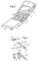
- fig. 5 shows how the pre-assembled microphone/conductor member shown in fig. 4 is arranged in the cover in the preferred embodiment of the telephone of the invention;
- fig. 6 shows the structure of the connector means of the telephone of the invention;
- fig. 7 shows the cover in the preferred embodiment of the telephone of the invention;
- fig. 8 shows how one of the resilient projections defining the discrete positions of the cover is constructed;
- fig. 9 illustrates the relation between the projections and the corresponding notches; and
- fig. 10 illustrates the position of the connector means of the telephone of the invention.
- A preferred embodiment of a
portable telephone 1 of the invention is shown in fig. 1. Thetelephone 1 has a microphone 10 (see fig. 4) arranged in aslidable cover 2, and an operatingface 5 which may be covered fully or partly by theslidable cover 2. The inner side of thecover 2 is formed with a plurality of metallic conductors 15 (see fig. 7), which are connected to the microphone 10, and which extend in the direction of the sliding movement of thecover 2. Thehousing 3 of thetelephone 1 is formed with a connector means 20 (see fig. 6) in the form ofslide shoes 21 for cooperation with theconductors 15. Theslide shoes 21 may advantageously be resilient. - The
housing 3 and thecover 2 of the telephone are of plastics, the materials selected being such as to provide movability between the parts. Further, both parts ideally have a perfect surface finish, and thehousing part 3 should be capable of being metallized, e.g. with aluminium owing to EMC. Finally, the parts should have a good mechanical stability. These properties may be obtained by using a polycarbonate (PC) to which polytetrafluoroethylene (PFTE) is added. The selection of materials is to impart a "self-lubricating effect" to the parts. - It will be seen from figs. 1-3 that the
telephone 1 and thereby thehousing 3 and thecover 2 are slightly curved. Thehousing 3 is moreover constructed with adisplay 4 to display e.g. called numbers, A-numbers, telephone menus, reception conditions and battery status. - The slidability between the
housing 3 and thecover 2 is obtained in the preferred embodiment in that the cover 2 (see fig. 7) has aside wall 16 in each side which terminates in an inwardly directedflange 17 curving slightly about an axis of curvature (not shown), which extends in parallel with the transverse direction of the telephone. Correspondingly, thetelephone housing 3 is formed withguide tracks 35 having a corresponding curvature. This means that the displacement between thecover 2 and thehousing 3 occurs along a circular arc. This will be seen clearly from figs. 1-3, which moreover show that the curvature is relatively slight, since the radius of the circle along which the movement takes place is large with respect to the length of the telephone. - In the position shown in fig. 1, the
cover 2 covers the entire operatingface 5 of the telephone. In case of an incoming call, this may be answered by sliding thecover 2 to the position shown in fig. 2, thereby making a first group of operatingpushbuttons 6 accessible. Further, the call may be answered merely by displacing thecover 2, as will be explained later. In the preferred embodiment, a call may also be answered by means of the volume pushbutton (up or down), which is not shown in the drawing, but is arranged at the side of the telephone. - This first group of operating
pushbuttons 6 may comprise a pushbutton for answering a call, a pushbutton for terminating a conversation, and menu control pushbuttons for operating programmed menu facilities of the telephone. Additional displacement of thecover 2 to the position shown in fig. 3 makes a final group of operatingpushbuttons 7 accessible, said group comprising essentially alpha-numerical pushbuttons used for establishing a call or for programming the telephone. - It moreover can be seen from figs. 1-3 that the
cover 2 has aridge 39 with one ormore apertures 40 through which the sound may pass. The microphone 10 is mounted interiorly in thecover 2 below theridge 39. - Fig. 4 shows how a
member 34 with microphone, flexible PCB and contact conductors are assembled before mounting in thecover 2. A flexible print 8 (PCB) has two conductingprint paths 15 of a length which approximately corresponds to the length of thecover 2. When mounted in thecover 2, theprint 8 extends in the direction of the sliding movement of the telephone. The microphone 10 is attached to the underside of theflexible print 8 and is electrically connected to the two conductingpaths 15 via anelectric filter 32. Arubber packing 33 is fitted loosely around the microphone 10 to provide mechanical protection, and a foam plastics member 9 is fitted on the rear side of theflexible print 8 to protect thefilter 32. The foam plastics member 9 has a flap which flexes about the edge of the print and covers the front side of it. Thepacking 33 and the foam plastics member 9 thus serve as acoustically suppressing elements. - A plastics sheet 12 (e.g. of polycarbonate) having two
longitudinal slots 13 is provided with adhesive on one side covered by a protectingrear side sheet 14. When therear side sheet 14 is removed, the plastics sheet may be attached (as a laminate) to the flexible print so that the conductingpaths 15 are accessible through theslots 13. The width of theplastics sheet 12 is greater than the width of theflexible print 8, so that portions of thesheet 12 with adhesive protrude along theflexible print 8. These protruding portions with adhesive are used in the mounting of theelement 34. - A
microphone holder 11 having amicrophone housing 18 surrounding the microphone 10 in themicrophone gasket 33, is then fitted. The resulting assembly ormember 34 is mounted on the inner side of thecover 2, which is formed with arecess 37 to receive themember 34 with microphone. The attachment is achieved in that themember 34 is assembled on some guide pins (not shown, but indicated by the dashed lines 36), whereby themember 34 is received accurately in therecess 37 in thecover 2. The fixation is provided in that themicrophone housing 18 with the microphone packing 33 fits in therecess 37, and that theflexible print 8 with thelabel 12 adheres to the face in therecess 37. When the position is correct, the adhesion is strengthened by ultrasonic welding of theprotective label 12 and themicrophone holder 11 to thecover 2 in some of the areas where there is direct engagement. - The connector means 20 shown in fig. 6 has the position shown in fig. 10 in the preferred embodiment of the telephone of the invention. The connector means 20 comprise two
slide shoes 21 which, upon displacement of thecover 2, slide against the respective conductingpath 15 and ensure a good electric connection in spite of the movement. It has been found that it is possible to transfer electric signals almost without noise - even when thecover 2 is displaced. - The connector means 20 has a
microswitch actuator 29 at the side of the slide shoes 21. In the closed position of thecover 2, themicroswitch actuator 29 cooperates with anactuation pin 38 on thecover 2, causing themicroswitch actuator 29 to be pressed down to engage anothercontact part 31, thereby closing a current path. It is hereby possible to detect when thecover 2 is in the position shown in fig. 1, the microswitch being closed here. When the current path in the microswitch is interrupted, a call may be answered without it being necessary to operate other pushbuttons. The conversation is terminated subsequently by closing the current path. The microswitch has twolegs 30 which are connected to the PCB of the telephone, while each of the slide shoes 21 has oneleg 30. - The slide shoes 21 have resilient properties to compensate for variations in the distance between the
cover 2 and thehousing 3. The slide shoes and themicroswitch actuator 29 are constructed as connector springs and are plated with 20 µm palladium nickel coated with 2 µm hard gold. The conducting paths 15 (slide flex) are plated with 5 µm hard gold. This ensures a wear-resisting and reliable electric connection. - It will be seen from fig. 8 that the rear part of the
housing 3 is provided with apocket 27 at each side capable of receiving and retaining therespective base parts 26 ofresilient members 25 when mounted. The upper part of thehousing 3 is removed. Eachresilient member 25 has an arm whoseend 24 extends out into theguide track 35 through an opening in thehousing 3, said member serving as a resilient projection engaged with thenotches 19 on theflange 17. Theprojection 24 and the threenotches 19 hereby define the three positions shown in figs. 1, 2 and 3. Positions between these three positions can be established, of course, but the three positions may easily be sensed when thecover 2 is displaced. The cooperation between theprojection 24 and the threenotches 19 is not enough per se to prevent thecover 2 from being pulled out of thehousing 3. Therefore, a shoulder or stop 23 is provided in connection with theguide track 35, preventing complete separation of the parts by cooperation with a locking boss on thecover 2. - However, for reasons of safety, the
cover 2 is given resilient properties which are sufficient to ensure that twisting of thecover 2 with respect to thetelephone housing 3 does not result in elastic deformation of thecover 2 so that itsside walls 16 with therail portions 17 are disengaged from the guide tracks 35 on thetelephone housing 3. For this reason, thestops 23 are formed with inclined guide faces permitting thecover 2 with the lockingbosses 22 to be easily placed in position again. - The telephone is provided with a timer (not shown) having a delay which delays the answer to a call for a period corresponding to a few seconds when a call is answered by means of the
slidable cover 2. This enables the user to interrupt/terminate the call before it is established. - Fig. 9 shows the
cover 2 in a position where it is to be slid inwardly over thestops 23 again. It is noted that the internal parts (pushbuttons, PCB, connector means, etc.) have not been mounted in thetelephone housing 3 as yet. Aspacer pin 28 supports thecover 2 when this is affected by a pressure on the telephone front face. This avoids separation by compression. - Fig. 10 shows the position of the connector means 20 below the operating
face 5. Apart from being without thecover 2, this telephone has not yet been provided with pushbuttons, PCB, etc. - Instead of the
continuous flanges 17, thecover 2 may be provided with discrete guide pins which are received in the guide tracks of thehousing 3. Alternatively, the guide tracks may be provided on thecover 2. - Some of the figures are provided with auxiliary lines to make the softly rounded shape of the telephone appear more clearly. In the preferred embodiment of the telephone of the invention, the conducting paths are placed on the cover, but the paths might just as well be provided on the telephone housing, with the connector means then mounted internally in the cover. In this case, the paths will be exposed when the cover is removed, which may involve some drawbacks.
- The present invention includes any novel feature or combination of features disclosed herein either explicitly or any generalisation thereof irrespective of whether or not it relates to the claimed invention or mitigates any or all of the problems addressed.
- In view of the foregoing description it will be evident to a person skilled in the art that various modifications may be made within the scope of the invention.
Claims (11)
- A radio telephone (1) comprising a housing (3) having an operating face (5), and a slideable cover (2) for sliding along at least a part of said operating face (5) and for covering at least a part of said operating face when the slideable cover is in closed position, comprising:a microphone (10) arranged in the slideable cover;a number of conductors (15);coupling means (20) for cooperation with said number of conductors (15) in order to connect said microphone (10) to electric parts in the telephone housing for a range of relative positions of the slidable cover (3) and operating face (5);characterized by
said conductors (15) extending in the direction of the sliding movement in said range of relative positions;
said coupling means (20) including a number of slide shoes (21) in sliding contact with a respective one of said conductors (15), and
said slide shoes (21) being formed as resilient metallic conductors biased towards the respective connector (15) in order to ensure the connection between the microphone (10) and the electric parts in a telephone housing for said range of positions of the cover (2) relative to the housing. - A radio telephone according to claim 1, wherein the inner side of the cover (2) is provided with said number of conductors (15), and wherein the telephone housing (3) is provided with the coupling means (20) that cooperate with said conductors (15).
- A radio telephone according to claim 1 or 2, wherein the telephone housing (3) is curved, and wherein a front face of the cover (2) essentially follows the operating face on the telephone housing.
- A radio telephone according to claims 1-3, wherein the cover (2) has two side walls (16) extending from the front face in the direction of the sliding movement of the cover (2), and wherein the two side walls and adjacent portions on the telephone housing are constructed as cooperating rails (17) and guide tracks to impart sidability to the cover (2).
- A radio telephone according to claim 4, wherein two side walls (16) are provided with rail (17) portions facing each other.
- A radio telephone according to claim 4 or 5, wherein resilient projections (24) are provided in connection with the guide tracks on the telephone housing (3), said projections (24) being adapted to cooperate with corresponding notches (19) in the rail portions (17) of the cover.
- A radio telephone according to claim 6, wherein the cooperating projections (24) and notches (17) define an intermediate position of the cover in which a first group of operating pushbuttons (6) are accessible.
- A radio telephone according to claim 6 or 7, wherein cooperating locking bosses (22) and shoulders (23) counteracting further displacement between the parts are provided in connection with the guide track projections and the rail portion notches in the extreme position of the cover (2).
- A radio telephone according to claim 8, wherein the cover (2) is given resilient properties sufficient to ensure that twisting of the cover (2) with respect to the telephone housing (3) results in elastic deformation of the cover, so that its side walls (16) with the rail portions (17) are disengaged from the guide tracks on the telephone housing (3).
- A radio telephone according to claim 1, wherein the front face of the cover (2) is provided with one or more through apertures (40) in connection with the microphone (10).
- A radio telephone according to claims 1-9, wherein the telephone (1) is provided with a contact (29, 30) which on-hooks the telephone when the cover (2) is slid to a position in which the operating face is covered.
Applications Claiming Priority (3)
| Application Number | Priority Date | Filing Date | Title |
|---|---|---|---|
| GB9603973AGB2310560B (en) | 1996-02-26 | 1996-02-26 | A radio telephone |
| GB9603973 | 1996-02-26 | ||
| US08/800,592US5956625A (en) | 1996-02-26 | 1997-02-18 | Radio telephone |
Publications (3)
| Publication Number | Publication Date |
|---|---|
| EP0792055A2 EP0792055A2 (en) | 1997-08-27 |
| EP0792055A3 EP0792055A3 (en) | 2001-02-28 |
| EP0792055B1true EP0792055B1 (en) | 2007-05-09 |
Family
ID=26308802
Family Applications (1)
| Application Number | Title | Priority Date | Filing Date |
|---|---|---|---|
| EP97301133AExpired - LifetimeEP0792055B1 (en) | 1996-02-26 | 1997-02-21 | A radio telephone |
Country Status (4)
| Country | Link |
|---|---|
| US (1) | US5956625A (en) |
| EP (1) | EP0792055B1 (en) |
| JP (1) | JPH09247252A (en) |
| GB (1) | GB2310560B (en) |
Families Citing this family (61)
| Publication number | Priority date | Publication date | Assignee | Title |
|---|---|---|---|---|
| WO1998058482A1 (en)* | 1997-06-19 | 1998-12-23 | Telefonaktiebolaget Lm Ericsson | Arrangement and method by a mobile transceiver |
| US6496181B1 (en)* | 1997-10-03 | 2002-12-17 | Siemens Information And Communication Mobile Llc | Scroll select-activate button for wireless terminals |
| GB2334850A (en)* | 1998-02-27 | 1999-09-01 | Nokia Mobile Phones Ltd | A communication device with a keyboard cover mounted upon sliding rods |
| FI112759B (en)* | 1998-03-18 | 2003-12-31 | Nokia Corp | Phone Telescope |
| US6243595B1 (en)* | 1998-06-16 | 2001-06-05 | Nortel Networks Limited | Portable wireless communication device having an extendible section |
| US6181324B1 (en)* | 1998-07-29 | 2001-01-30 | Donald T. Lamb | Portable weather display device |
| GB2340333B (en)* | 1998-08-04 | 2002-07-31 | Nokia Mobile Phones Ltd | Radio telephone |
| US6208874B1 (en)* | 1998-11-02 | 2001-03-27 | Ericsson Inc. | Telephone assembly with automatic antenna adjustment |
| FI116029B (en) | 1998-12-22 | 2005-08-31 | Nokia Corp | Design of the telescopic housing of an electrical appliance |
| US6249672B1 (en)* | 1999-03-19 | 2001-06-19 | Mobile Communications Holdings, Inc. | Portable telephone |
| JP4298054B2 (en)* | 1999-04-23 | 2009-07-15 | パナソニック株式会社 | Portable wireless device |
| US6542721B2 (en)* | 1999-10-11 | 2003-04-01 | Peter V. Boesen | Cellular telephone, personal digital assistant and pager unit |
| USD427171S (en)* | 1999-06-14 | 2000-06-27 | Nokia Mobile Phones Limited | Handset |
| USD425074S (en)* | 1999-06-14 | 2000-05-16 | Nokia Mobile Phones Limited | Front cover for a telephone handset |
| GB2351616B (en)* | 1999-06-30 | 2003-11-12 | Nokia Mobile Phones Ltd | A radiotelephone |
| GB2353170A (en) | 1999-08-06 | 2001-02-14 | Nokia Mobile Phones Ltd | Slide assembly for a communication unit |
| JP2001119457A (en) | 1999-10-15 | 2001-04-27 | Matsushita Electric Ind Co Ltd | Mobile phone equipment |
| AU140871S (en) | 2000-01-20 | 2000-06-14 | Nokia Mobile Phones Ltd | A handset |
| FI112422B (en) | 2000-04-28 | 2003-11-28 | Nokia Corp | Telescope structure for a telephone set |
| CA2314204A1 (en)* | 2000-07-21 | 2002-01-21 | Digital Security Controls Ltd. | Key fob with slidable cover |
| US6600904B1 (en)* | 2000-09-12 | 2003-07-29 | Hong-Chun Wang | Structure of a bracket component for the press button of a mobile phone |
| KR20020088214A (en)* | 2001-05-18 | 2002-11-27 | (주)도움 | Wireless Mobile Phone with Slide Module |
| WO2002100076A1 (en)* | 2001-05-31 | 2002-12-12 | Nippon Tojix Co., Ltd. | Cellular telephone |
| USD455137S1 (en) | 2001-06-13 | 2002-04-02 | Hon Hai Precision Ind. Co., Ltd. | Mobile phone |
| US7069063B2 (en) | 2001-06-19 | 2006-06-27 | Nokia Mobile Phones Limited | User changeable mobile phone cover |
| US20030003962A1 (en)* | 2001-06-29 | 2003-01-02 | Tan Vooi-Kia | Automatic sliding machanism for portable electronic product, particularly for a sliding front cover of a mobile phone |
| US7692667B2 (en)* | 2001-08-17 | 2010-04-06 | Palm, Inc. | Handheld computer having moveable segments that are interactive with an integrated display |
| JP2003179678A (en)* | 2001-10-03 | 2003-06-27 | Nec Corp | Portable telephone |
| US6950516B2 (en)* | 2001-10-05 | 2005-09-27 | Nokia Corporation | User changeable electronic device/mobile phone covers and method |
| AU147872S (en) | 2001-10-12 | 2002-05-20 | Nokia Corp | A front cover for a handset |
| JP3856682B2 (en)* | 2001-10-15 | 2006-12-13 | 加藤電機株式会社 | Slide mechanism |
| US6665909B2 (en)* | 2001-12-14 | 2003-12-23 | Medtronic Minimed, Inc. | Low-profile mounting clip for personal device |
| USD482686S1 (en) | 2002-01-22 | 2003-11-25 | Nokia Corporation | Front cover for a handset |
| KR100605862B1 (en)* | 2002-07-02 | 2006-07-31 | 삼성전자주식회사 | Sliding type wireless terminal |
| DE10258183B3 (en) | 2002-12-12 | 2004-07-29 | Siemens Ag | Slider mobile phone with flexible shaft loudspeaker |
| KR100511305B1 (en)* | 2003-04-15 | 2005-08-31 | 엘지전자 주식회사 | A structure and a device and a method of selecting menu for slide type mobile phone |
| US7672699B2 (en)* | 2003-06-19 | 2010-03-02 | Samsung Electronics Co., Ltd. | Driving apparatus using magnetic substance for sliding type portable wireless terminal |
| US20050054397A1 (en)* | 2003-09-08 | 2005-03-10 | Samsung Electronics Co., Ltd. | Portable sliding-type digital communication device and locking apparatus thereof |
| JP3944506B2 (en)* | 2003-10-28 | 2007-07-11 | エルジー エレクトロニクス インコーポレイティド | SLIDING TYPE PORTABLE TERMINAL AND SLIDING DEVICE USED FOR THE SAME |
| JP2005167488A (en)* | 2003-12-01 | 2005-06-23 | Kato Electrical Mach Co Ltd | Sliding mechanism of portable terminal |
| TWM256048U (en)* | 2003-12-30 | 2005-01-21 | Inventec Multimedia & Telecom | Housing device of handheld electronic product |
| JP2005295312A (en)* | 2004-04-01 | 2005-10-20 | Hitachi Ltd | Portable wireless device |
| TWM260061U (en)* | 2004-06-11 | 2005-03-21 | Quanta Comp Inc | Automatic sliding mechanism |
| KR100630559B1 (en)* | 2004-08-10 | 2006-09-29 | 주식회사 팬택 | Slim Mobile Communication Terminal |
| KR100661992B1 (en) | 2005-02-04 | 2006-12-28 | 주식회사 엠투시스 | Sliding switchgear of portable terminal |
| KR100617673B1 (en)* | 2004-12-06 | 2006-08-28 | 삼성전자주식회사 | Sliding module of sliding type mobile terminal and sliding type mobile terminal employing same |
| FI124480B (en)* | 2006-07-19 | 2014-09-15 | Mendor Oy | device Breeding |
| US20080057949A1 (en)* | 2006-08-31 | 2008-03-06 | Martin Wraber Christensen | Method for operating a mobile communication device and mobile communication device |
| KR101119113B1 (en)* | 2006-09-29 | 2012-03-16 | 엘지전자 주식회사 | terminal |
| JP5088367B2 (en)* | 2007-03-23 | 2012-12-05 | 日本電気株式会社 | Slide mechanism for housing, slide opening / closing housing, and mobile phone |
| KR101551453B1 (en) | 2007-09-28 | 2015-09-08 | 회가내스 아베 (피유비엘) | Metallurgical powder composition and method of production |
| CN101426039A (en)* | 2007-10-31 | 2009-05-06 | 鸿富锦精密工业(深圳)有限公司 | Portable electronic device protection case |
| US8204557B1 (en)* | 2008-07-28 | 2012-06-19 | Sprint Communications Company L.P. | Wireless communications device assembly |
| JP5317180B2 (en) | 2008-11-25 | 2013-10-16 | 日本電気株式会社 | Flexible printed circuit board mounting structure and sliding electronic device |
| CN101931668B (en)* | 2009-06-18 | 2013-06-05 | 深圳富泰宏精密工业有限公司 | Sliding cover mechanism and portable electronic device with same |
| TWI454204B (en)* | 2009-07-10 | 2014-09-21 | Chi Mei Comm Systems Inc | Sliding mechanism and portable electronic device with the same |
| JP2011109354A (en)* | 2009-11-17 | 2011-06-02 | Fujitsu Toshiba Mobile Communications Ltd | Mobile terminal |
| TWM388826U (en)* | 2010-04-30 | 2010-09-11 | Hon Hai Prec Ind Co Ltd | Sliding apparatus |
| USD686209S1 (en)* | 2012-04-05 | 2013-07-16 | Inmusic Brands, Inc. | Game controller |
| GB2521448B (en)* | 2013-12-20 | 2021-07-21 | Nokia Technologies Oy | An apparatus and method for providing an apparatus comprising a covering portion for an electronic device |
| USD883246S1 (en)* | 2017-11-14 | 2020-05-05 | Hmd Global Oy | Mobile phone |
Family Cites Families (6)
| Publication number | Priority date | Publication date | Assignee | Title |
|---|---|---|---|---|
| DE3836406A1 (en)* | 1988-10-26 | 1990-05-03 | Bosch Gmbh Robert | Handset-shaped mobile operating unit |
| GB2235606B (en)* | 1989-08-24 | 1994-03-30 | Technophone Ltd | Portable telephone |
| AU9100091A (en)* | 1990-11-16 | 1992-06-11 | Universal Cellular, Inc. | Portable telephone housing |
| JP2689785B2 (en)* | 1991-09-30 | 1997-12-10 | 日本電気株式会社 | Small portable radio |
| JPH0645982A (en)* | 1992-07-22 | 1994-02-18 | Sony Corp | Portable radio telephone set |
| JP2595932B2 (en)* | 1994-05-18 | 1997-04-02 | 日本電気株式会社 | Portable radio |
- 1996
- 1996-02-26GBGB9603973Apatent/GB2310560B/ennot_activeExpired - Fee Related
- 1997
- 1997-02-18USUS08/800,592patent/US5956625A/ennot_activeExpired - Lifetime
- 1997-02-21EPEP97301133Apatent/EP0792055B1/ennot_activeExpired - Lifetime
- 1997-02-25JPJP9039603Apatent/JPH09247252A/enactivePending
Non-Patent Citations (1)
| Title |
|---|
| None* |
Also Published As
| Publication number | Publication date |
|---|---|
| JPH09247252A (en) | 1997-09-19 |
| EP0792055A3 (en) | 2001-02-28 |
| US5956625A (en) | 1999-09-21 |
| GB2310560B (en) | 2000-07-12 |
| GB9603973D0 (en) | 1996-04-24 |
| EP0792055A2 (en) | 1997-08-27 |
| GB2310560A (en) | 1997-08-27 |
Similar Documents
| Publication | Publication Date | Title |
|---|---|---|
| EP0792055B1 (en) | A radio telephone | |
| US6463262B1 (en) | Radio telephone | |
| US6370362B1 (en) | Slide cover for a communication unit | |
| EP1610531B1 (en) | Method of Operating a Radio Telephone | |
| US20020006813A1 (en) | Electronic equipment comprising a retractable screen | |
| CA2282397C (en) | Microphone attachment for electrically connecting the microphone and audio circuit of a flip-type radio phone with a mechanical contact device | |
| EP1919011B1 (en) | Battery cover grounding device for portable terminal | |
| WO1999012322A1 (en) | Radiotelephone with sliding acoustic member | |
| WO2000008722A1 (en) | Moisture resistant electrical connector for a cellular telephone | |
| EP1439685B1 (en) | Flip-phone cover | |
| AU716388B2 (en) | A radio telephone | |
| US3384718A (en) | Telephone handset housing | |
| GB2310562A (en) | Function of permanently exposed key depends on cover position | |
| CN216507836U (en) | Door switch and vehicle | |
| KR100247023B1 (en) | Hinge mechanism for flip-type radiotelephone | |
| CA1144204A (en) | Seal for a sliding actuator for a linear control member | |
| KR100222430B1 (en) | Microphone device of flip typed portable terminal | |
| JPH11155238A (en) | Charging-terminal protective structure in portable telephone and the like | |
| JP2001086027A (en) | Microphone for communication device |
Legal Events
| Date | Code | Title | Description |
|---|---|---|---|
| PUAI | Public reference made under article 153(3) epc to a published international application that has entered the european phase | Free format text:ORIGINAL CODE: 0009012 | |
| AK | Designated contracting states | Kind code of ref document:A2 Designated state(s):AT CH DE DK ES FI FR GB IT LI NL SE | |
| PUAL | Search report despatched | Free format text:ORIGINAL CODE: 0009013 | |
| AK | Designated contracting states | Kind code of ref document:A3 Designated state(s):AT CH DE DK ES FI FR GB IT LI NL SE | |
| 17P | Request for examination filed | Effective date:20010828 | |
| RAP1 | Party data changed (applicant data changed or rights of an application transferred) | Owner name:NOKIA CORPORATION | |
| 17Q | First examination report despatched | Effective date:20050621 | |
| GRAP | Despatch of communication of intention to grant a patent | Free format text:ORIGINAL CODE: EPIDOSNIGR1 | |
| GRAS | Grant fee paid | Free format text:ORIGINAL CODE: EPIDOSNIGR3 | |
| GRAA | (expected) grant | Free format text:ORIGINAL CODE: 0009210 | |
| AK | Designated contracting states | Kind code of ref document:B1 Designated state(s):AT CH DE DK ES FI FR GB IT LI NL SE | |
| PG25 | Lapsed in a contracting state [announced via postgrant information from national office to epo] | Ref country code:LI Free format text:LAPSE BECAUSE OF FAILURE TO SUBMIT A TRANSLATION OF THE DESCRIPTION OR TO PAY THE FEE WITHIN THE PRESCRIBED TIME-LIMIT Effective date:20070509 Ref country code:CH Free format text:LAPSE BECAUSE OF FAILURE TO SUBMIT A TRANSLATION OF THE DESCRIPTION OR TO PAY THE FEE WITHIN THE PRESCRIBED TIME-LIMIT Effective date:20070509 | |
| REG | Reference to a national code | Ref country code:GB Ref legal event code:FG4D | |
| REG | Reference to a national code | Ref country code:CH Ref legal event code:EP | |
| REF | Corresponds to: | Ref document number:69737707 Country of ref document:DE Date of ref document:20070621 Kind code of ref document:P | |
| REG | Reference to a national code | Ref country code:SE Ref legal event code:TRGR | |
| ET | Fr: translation filed | ||
| REG | Reference to a national code | Ref country code:CH Ref legal event code:PL | |
| REG | Reference to a national code | Ref country code:ES Ref legal event code:FG2A Ref document number:2285723 Country of ref document:ES Kind code of ref document:T3 | |
| PG25 | Lapsed in a contracting state [announced via postgrant information from national office to epo] | Ref country code:AT Free format text:LAPSE BECAUSE OF FAILURE TO SUBMIT A TRANSLATION OF THE DESCRIPTION OR TO PAY THE FEE WITHIN THE PRESCRIBED TIME-LIMIT Effective date:20070509 | |
| PG25 | Lapsed in a contracting state [announced via postgrant information from national office to epo] | Ref country code:DK Free format text:LAPSE BECAUSE OF FAILURE TO SUBMIT A TRANSLATION OF THE DESCRIPTION OR TO PAY THE FEE WITHIN THE PRESCRIBED TIME-LIMIT Effective date:20070509 | |
| PLBE | No opposition filed within time limit | Free format text:ORIGINAL CODE: 0009261 | |
| STAA | Information on the status of an ep patent application or granted ep patent | Free format text:STATUS: NO OPPOSITION FILED WITHIN TIME LIMIT | |
| 26N | No opposition filed | Effective date:20080212 | |
| PGFP | Annual fee paid to national office [announced via postgrant information from national office to epo] | Ref country code:FR Payment date:20110218 Year of fee payment:15 Ref country code:IT Payment date:20110216 Year of fee payment:15 Ref country code:NL Payment date:20110216 Year of fee payment:15 Ref country code:FI Payment date:20110211 Year of fee payment:15 Ref country code:DE Payment date:20110216 Year of fee payment:15 Ref country code:SE Payment date:20110211 Year of fee payment:15 | |
| PGFP | Annual fee paid to national office [announced via postgrant information from national office to epo] | Ref country code:ES Payment date:20110315 Year of fee payment:15 Ref country code:GB Payment date:20110216 Year of fee payment:15 | |
| REG | Reference to a national code | Ref country code:NL Ref legal event code:V1 Effective date:20120901 | |
| GBPC | Gb: european patent ceased through non-payment of renewal fee | Effective date:20120221 | |
| PG25 | Lapsed in a contracting state [announced via postgrant information from national office to epo] | Ref country code:FI Free format text:LAPSE BECAUSE OF NON-PAYMENT OF DUE FEES Effective date:20120221 Ref country code:SE Free format text:LAPSE BECAUSE OF NON-PAYMENT OF DUE FEES Effective date:20120222 | |
| REG | Reference to a national code | Ref country code:FR Ref legal event code:ST Effective date:20121031 | |
| PG25 | Lapsed in a contracting state [announced via postgrant information from national office to epo] | Ref country code:IT Free format text:LAPSE BECAUSE OF NON-PAYMENT OF DUE FEES Effective date:20120221 | |
| REG | Reference to a national code | Ref country code:DE Ref legal event code:R119 Ref document number:69737707 Country of ref document:DE Effective date:20120901 | |
| PG25 | Lapsed in a contracting state [announced via postgrant information from national office to epo] | Ref country code:NL Free format text:LAPSE BECAUSE OF NON-PAYMENT OF DUE FEES Effective date:20120901 Ref country code:GB Free format text:LAPSE BECAUSE OF NON-PAYMENT OF DUE FEES Effective date:20120221 Ref country code:FR Free format text:LAPSE BECAUSE OF NON-PAYMENT OF DUE FEES Effective date:20120229 | |
| PG25 | Lapsed in a contracting state [announced via postgrant information from national office to epo] | Ref country code:DE Free format text:LAPSE BECAUSE OF NON-PAYMENT OF DUE FEES Effective date:20120901 | |
| REG | Reference to a national code | Ref country code:ES Ref legal event code:FD2A Effective date:20130708 | |
| PG25 | Lapsed in a contracting state [announced via postgrant information from national office to epo] | Ref country code:ES Free format text:LAPSE BECAUSE OF NON-PAYMENT OF DUE FEES Effective date:20120222 |