EP0791342A1 - Femoral neck endoprosthesis for an artificial hip joint - Google Patents
Femoral neck endoprosthesis for an artificial hip jointDownload PDFInfo
- Publication number
- EP0791342A1 EP0791342A1EP97100111AEP97100111AEP0791342A1EP 0791342 A1EP0791342 A1EP 0791342A1EP 97100111 AEP97100111 AEP 97100111AEP 97100111 AEP97100111 AEP 97100111AEP 0791342 A1EP0791342 A1EP 0791342A1
- Authority
- EP
- European Patent Office
- Prior art keywords
- sleeve
- femoral neck
- femur
- adapter
- endoprosthesis
- Prior art date
- Legal status (The legal status is an assumption and is not a legal conclusion. Google has not performed a legal analysis and makes no representation as to the accuracy of the status listed.)
- Granted
Links
- 210000004394hip jointAnatomy0.000titleclaimsabstractdescription8
- 210000002436femur neckAnatomy0.000titleclaimsdescription21
- 210000000689upper legAnatomy0.000claimsabstractdescription43
- 210000000527greater trochanterAnatomy0.000claimsabstract2
- 239000004568cementSubstances0.000abstractdescription3
- 210000000988bone and boneAnatomy0.000description26
- 238000002513implantationMethods0.000description11
- 238000002271resectionMethods0.000description10
- 230000000694effectsEffects0.000description7
- 241000209035IlexSpecies0.000description4
- 239000000463materialSubstances0.000description4
- 241000309551Arthraxon hispidusSpecies0.000description3
- 230000006978adaptationEffects0.000description3
- 210000001185bone marrowAnatomy0.000description3
- 230000035876healingEffects0.000description3
- 210000001624hipAnatomy0.000description3
- 239000007943implantSubstances0.000description3
- 210000000528lesser trochanterAnatomy0.000description3
- 238000005452bendingMethods0.000description2
- 230000007774longtermEffects0.000description2
- 238000001356surgical procedureMethods0.000description2
- 241000826860TrapeziumSpecies0.000description1
- 238000013459approachMethods0.000description1
- 239000002639bone cementSubstances0.000description1
- 230000001447compensatory effectEffects0.000description1
- 230000001054cortical effectEffects0.000description1
- 238000005516engineering processMethods0.000description1
- 230000002349favourable effectEffects0.000description1
- 230000006870functionEffects0.000description1
- 238000011065in-situ storageMethods0.000description1
- 230000003993interactionEffects0.000description1
- 238000000034methodMethods0.000description1
- 238000003801millingMethods0.000description1
- 230000008058pain sensationEffects0.000description1
- 230000002093peripheral effectEffects0.000description1
- 230000010076replicationEffects0.000description1
- 239000000725suspensionSubstances0.000description1
- 230000001225therapeutic effectEffects0.000description1
- 210000001519tissueAnatomy0.000description1
Images


Classifications
- A—HUMAN NECESSITIES
- A61—MEDICAL OR VETERINARY SCIENCE; HYGIENE
- A61F—FILTERS IMPLANTABLE INTO BLOOD VESSELS; PROSTHESES; DEVICES PROVIDING PATENCY TO, OR PREVENTING COLLAPSING OF, TUBULAR STRUCTURES OF THE BODY, e.g. STENTS; ORTHOPAEDIC, NURSING OR CONTRACEPTIVE DEVICES; FOMENTATION; TREATMENT OR PROTECTION OF EYES OR EARS; BANDAGES, DRESSINGS OR ABSORBENT PADS; FIRST-AID KITS
- A61F2/00—Filters implantable into blood vessels; Prostheses, i.e. artificial substitutes or replacements for parts of the body; Appliances for connecting them with the body; Devices providing patency to, or preventing collapsing of, tubular structures of the body, e.g. stents
- A61F2/02—Prostheses implantable into the body
- A61F2/30—Joints
- A61F2/30767—Special external or bone-contacting surface, e.g. coating for improving bone ingrowth
- A61F2/30907—Nets or sleeves applied to surface of prostheses or in cement
- A—HUMAN NECESSITIES
- A61—MEDICAL OR VETERINARY SCIENCE; HYGIENE
- A61F—FILTERS IMPLANTABLE INTO BLOOD VESSELS; PROSTHESES; DEVICES PROVIDING PATENCY TO, OR PREVENTING COLLAPSING OF, TUBULAR STRUCTURES OF THE BODY, e.g. STENTS; ORTHOPAEDIC, NURSING OR CONTRACEPTIVE DEVICES; FOMENTATION; TREATMENT OR PROTECTION OF EYES OR EARS; BANDAGES, DRESSINGS OR ABSORBENT PADS; FIRST-AID KITS
- A61F2/00—Filters implantable into blood vessels; Prostheses, i.e. artificial substitutes or replacements for parts of the body; Appliances for connecting them with the body; Devices providing patency to, or preventing collapsing of, tubular structures of the body, e.g. stents
- A61F2/02—Prostheses implantable into the body
- A61F2/30—Joints
- A61F2/32—Joints for the hip
- A61F2/36—Femoral heads ; Femoral endoprostheses
- A61F2/3601—Femoral heads ; Femoral endoprostheses for replacing only the epiphyseal or metaphyseal parts of the femur, e.g. endoprosthetic femoral heads or necks directly fixed to the natural femur by internal fixation devices
- A—HUMAN NECESSITIES
- A61—MEDICAL OR VETERINARY SCIENCE; HYGIENE
- A61B—DIAGNOSIS; SURGERY; IDENTIFICATION
- A61B17/00—Surgical instruments, devices or methods
- A61B17/56—Surgical instruments or methods for treatment of bones or joints; Devices specially adapted therefor
- A61B17/58—Surgical instruments or methods for treatment of bones or joints; Devices specially adapted therefor for osteosynthesis, e.g. bone plates, screws or setting implements
- A61B17/68—Internal fixation devices, including fasteners and spinal fixators, even if a part thereof projects from the skin
- A61B17/74—Devices for the head or neck or trochanter of the femur
- A61B17/742—Devices for the head or neck or trochanter of the femur having one or more longitudinal elements oriented along or parallel to the axis of the neck
- A—HUMAN NECESSITIES
- A61—MEDICAL OR VETERINARY SCIENCE; HYGIENE
- A61B—DIAGNOSIS; SURGERY; IDENTIFICATION
- A61B17/00—Surgical instruments, devices or methods
- A61B17/56—Surgical instruments or methods for treatment of bones or joints; Devices specially adapted therefor
- A61B17/58—Surgical instruments or methods for treatment of bones or joints; Devices specially adapted therefor for osteosynthesis, e.g. bone plates, screws or setting implements
- A61B17/68—Internal fixation devices, including fasteners and spinal fixators, even if a part thereof projects from the skin
- A61B17/80—Cortical plates, i.e. bone plates; Instruments for holding or positioning cortical plates, or for compressing bones attached to cortical plates
- A—HUMAN NECESSITIES
- A61—MEDICAL OR VETERINARY SCIENCE; HYGIENE
- A61F—FILTERS IMPLANTABLE INTO BLOOD VESSELS; PROSTHESES; DEVICES PROVIDING PATENCY TO, OR PREVENTING COLLAPSING OF, TUBULAR STRUCTURES OF THE BODY, e.g. STENTS; ORTHOPAEDIC, NURSING OR CONTRACEPTIVE DEVICES; FOMENTATION; TREATMENT OR PROTECTION OF EYES OR EARS; BANDAGES, DRESSINGS OR ABSORBENT PADS; FIRST-AID KITS
- A61F2/00—Filters implantable into blood vessels; Prostheses, i.e. artificial substitutes or replacements for parts of the body; Appliances for connecting them with the body; Devices providing patency to, or preventing collapsing of, tubular structures of the body, e.g. stents
- A61F2/02—Prostheses implantable into the body
- A61F2/30—Joints
- A61F2/30721—Accessories
- A61F2/30749—Fixation appliances for connecting prostheses to the body
- A—HUMAN NECESSITIES
- A61—MEDICAL OR VETERINARY SCIENCE; HYGIENE
- A61F—FILTERS IMPLANTABLE INTO BLOOD VESSELS; PROSTHESES; DEVICES PROVIDING PATENCY TO, OR PREVENTING COLLAPSING OF, TUBULAR STRUCTURES OF THE BODY, e.g. STENTS; ORTHOPAEDIC, NURSING OR CONTRACEPTIVE DEVICES; FOMENTATION; TREATMENT OR PROTECTION OF EYES OR EARS; BANDAGES, DRESSINGS OR ABSORBENT PADS; FIRST-AID KITS
- A61F2/00—Filters implantable into blood vessels; Prostheses, i.e. artificial substitutes or replacements for parts of the body; Appliances for connecting them with the body; Devices providing patency to, or preventing collapsing of, tubular structures of the body, e.g. stents
- A61F2/02—Prostheses implantable into the body
- A61F2/30—Joints
- A61F2002/30001—Additional features of subject-matter classified in A61F2/28, A61F2/30 and subgroups thereof
- A61F2002/30108—Shapes
- A61F2002/3011—Cross-sections or two-dimensional shapes
- A61F2002/30112—Rounded shapes, e.g. with rounded corners
- A61F2002/30125—Rounded shapes, e.g. with rounded corners elliptical or oval
- A—HUMAN NECESSITIES
- A61—MEDICAL OR VETERINARY SCIENCE; HYGIENE
- A61F—FILTERS IMPLANTABLE INTO BLOOD VESSELS; PROSTHESES; DEVICES PROVIDING PATENCY TO, OR PREVENTING COLLAPSING OF, TUBULAR STRUCTURES OF THE BODY, e.g. STENTS; ORTHOPAEDIC, NURSING OR CONTRACEPTIVE DEVICES; FOMENTATION; TREATMENT OR PROTECTION OF EYES OR EARS; BANDAGES, DRESSINGS OR ABSORBENT PADS; FIRST-AID KITS
- A61F2/00—Filters implantable into blood vessels; Prostheses, i.e. artificial substitutes or replacements for parts of the body; Appliances for connecting them with the body; Devices providing patency to, or preventing collapsing of, tubular structures of the body, e.g. stents
- A61F2/02—Prostheses implantable into the body
- A61F2/30—Joints
- A61F2002/30001—Additional features of subject-matter classified in A61F2/28, A61F2/30 and subgroups thereof
- A61F2002/30108—Shapes
- A61F2002/30199—Three-dimensional shapes
- A61F2002/30205—Three-dimensional shapes conical
- A61F2002/3021—Three-dimensional shapes conical frustoconical
- A—HUMAN NECESSITIES
- A61—MEDICAL OR VETERINARY SCIENCE; HYGIENE
- A61F—FILTERS IMPLANTABLE INTO BLOOD VESSELS; PROSTHESES; DEVICES PROVIDING PATENCY TO, OR PREVENTING COLLAPSING OF, TUBULAR STRUCTURES OF THE BODY, e.g. STENTS; ORTHOPAEDIC, NURSING OR CONTRACEPTIVE DEVICES; FOMENTATION; TREATMENT OR PROTECTION OF EYES OR EARS; BANDAGES, DRESSINGS OR ABSORBENT PADS; FIRST-AID KITS
- A61F2/00—Filters implantable into blood vessels; Prostheses, i.e. artificial substitutes or replacements for parts of the body; Appliances for connecting them with the body; Devices providing patency to, or preventing collapsing of, tubular structures of the body, e.g. stents
- A61F2/02—Prostheses implantable into the body
- A61F2/30—Joints
- A61F2002/30001—Additional features of subject-matter classified in A61F2/28, A61F2/30 and subgroups thereof
- A61F2002/30108—Shapes
- A61F2002/30199—Three-dimensional shapes
- A61F2002/30205—Three-dimensional shapes conical
- A61F2002/30217—Three-dimensional shapes conical hollow cones, e.g. tubular-like cones
- A—HUMAN NECESSITIES
- A61—MEDICAL OR VETERINARY SCIENCE; HYGIENE
- A61F—FILTERS IMPLANTABLE INTO BLOOD VESSELS; PROSTHESES; DEVICES PROVIDING PATENCY TO, OR PREVENTING COLLAPSING OF, TUBULAR STRUCTURES OF THE BODY, e.g. STENTS; ORTHOPAEDIC, NURSING OR CONTRACEPTIVE DEVICES; FOMENTATION; TREATMENT OR PROTECTION OF EYES OR EARS; BANDAGES, DRESSINGS OR ABSORBENT PADS; FIRST-AID KITS
- A61F2/00—Filters implantable into blood vessels; Prostheses, i.e. artificial substitutes or replacements for parts of the body; Appliances for connecting them with the body; Devices providing patency to, or preventing collapsing of, tubular structures of the body, e.g. stents
- A61F2/02—Prostheses implantable into the body
- A61F2/30—Joints
- A61F2002/30001—Additional features of subject-matter classified in A61F2/28, A61F2/30 and subgroups thereof
- A61F2002/30316—The prosthesis having different structural features at different locations within the same prosthesis; Connections between prosthetic parts; Special structural features of bone or joint prostheses not otherwise provided for
- A61F2002/30329—Connections or couplings between prosthetic parts, e.g. between modular parts; Connecting elements
- A61F2002/30331—Connections or couplings between prosthetic parts, e.g. between modular parts; Connecting elements made by longitudinally pushing a protrusion into a complementarily-shaped recess, e.g. held by friction fit
- A61F2002/30332—Conically- or frustoconically-shaped protrusion and recess
- A61F2002/30339—Double cones, i.e. connecting element having two conical connections, one at each of its opposite ends
- A—HUMAN NECESSITIES
- A61—MEDICAL OR VETERINARY SCIENCE; HYGIENE
- A61F—FILTERS IMPLANTABLE INTO BLOOD VESSELS; PROSTHESES; DEVICES PROVIDING PATENCY TO, OR PREVENTING COLLAPSING OF, TUBULAR STRUCTURES OF THE BODY, e.g. STENTS; ORTHOPAEDIC, NURSING OR CONTRACEPTIVE DEVICES; FOMENTATION; TREATMENT OR PROTECTION OF EYES OR EARS; BANDAGES, DRESSINGS OR ABSORBENT PADS; FIRST-AID KITS
- A61F2/00—Filters implantable into blood vessels; Prostheses, i.e. artificial substitutes or replacements for parts of the body; Appliances for connecting them with the body; Devices providing patency to, or preventing collapsing of, tubular structures of the body, e.g. stents
- A61F2/02—Prostheses implantable into the body
- A61F2/30—Joints
- A61F2002/30001—Additional features of subject-matter classified in A61F2/28, A61F2/30 and subgroups thereof
- A61F2002/30316—The prosthesis having different structural features at different locations within the same prosthesis; Connections between prosthetic parts; Special structural features of bone or joint prostheses not otherwise provided for
- A61F2002/30329—Connections or couplings between prosthetic parts, e.g. between modular parts; Connecting elements
- A61F2002/30405—Connections or couplings between prosthetic parts, e.g. between modular parts; Connecting elements made by screwing complementary threads machined on the parts themselves
- A—HUMAN NECESSITIES
- A61—MEDICAL OR VETERINARY SCIENCE; HYGIENE
- A61F—FILTERS IMPLANTABLE INTO BLOOD VESSELS; PROSTHESES; DEVICES PROVIDING PATENCY TO, OR PREVENTING COLLAPSING OF, TUBULAR STRUCTURES OF THE BODY, e.g. STENTS; ORTHOPAEDIC, NURSING OR CONTRACEPTIVE DEVICES; FOMENTATION; TREATMENT OR PROTECTION OF EYES OR EARS; BANDAGES, DRESSINGS OR ABSORBENT PADS; FIRST-AID KITS
- A61F2/00—Filters implantable into blood vessels; Prostheses, i.e. artificial substitutes or replacements for parts of the body; Appliances for connecting them with the body; Devices providing patency to, or preventing collapsing of, tubular structures of the body, e.g. stents
- A61F2/02—Prostheses implantable into the body
- A61F2/30—Joints
- A61F2002/30001—Additional features of subject-matter classified in A61F2/28, A61F2/30 and subgroups thereof
- A61F2002/30316—The prosthesis having different structural features at different locations within the same prosthesis; Connections between prosthetic parts; Special structural features of bone or joint prostheses not otherwise provided for
- A61F2002/30329—Connections or couplings between prosthetic parts, e.g. between modular parts; Connecting elements
- A61F2002/30433—Connections or couplings between prosthetic parts, e.g. between modular parts; Connecting elements using additional screws, bolts, dowels, rivets or washers e.g. connecting screws
- A—HUMAN NECESSITIES
- A61—MEDICAL OR VETERINARY SCIENCE; HYGIENE
- A61F—FILTERS IMPLANTABLE INTO BLOOD VESSELS; PROSTHESES; DEVICES PROVIDING PATENCY TO, OR PREVENTING COLLAPSING OF, TUBULAR STRUCTURES OF THE BODY, e.g. STENTS; ORTHOPAEDIC, NURSING OR CONTRACEPTIVE DEVICES; FOMENTATION; TREATMENT OR PROTECTION OF EYES OR EARS; BANDAGES, DRESSINGS OR ABSORBENT PADS; FIRST-AID KITS
- A61F2/00—Filters implantable into blood vessels; Prostheses, i.e. artificial substitutes or replacements for parts of the body; Appliances for connecting them with the body; Devices providing patency to, or preventing collapsing of, tubular structures of the body, e.g. stents
- A61F2/02—Prostheses implantable into the body
- A61F2/30—Joints
- A61F2002/30001—Additional features of subject-matter classified in A61F2/28, A61F2/30 and subgroups thereof
- A61F2002/30316—The prosthesis having different structural features at different locations within the same prosthesis; Connections between prosthetic parts; Special structural features of bone or joint prostheses not otherwise provided for
- A61F2002/30535—Special structural features of bone or joint prostheses not otherwise provided for
- A61F2002/30604—Special structural features of bone or joint prostheses not otherwise provided for modular
- A—HUMAN NECESSITIES
- A61—MEDICAL OR VETERINARY SCIENCE; HYGIENE
- A61F—FILTERS IMPLANTABLE INTO BLOOD VESSELS; PROSTHESES; DEVICES PROVIDING PATENCY TO, OR PREVENTING COLLAPSING OF, TUBULAR STRUCTURES OF THE BODY, e.g. STENTS; ORTHOPAEDIC, NURSING OR CONTRACEPTIVE DEVICES; FOMENTATION; TREATMENT OR PROTECTION OF EYES OR EARS; BANDAGES, DRESSINGS OR ABSORBENT PADS; FIRST-AID KITS
- A61F2/00—Filters implantable into blood vessels; Prostheses, i.e. artificial substitutes or replacements for parts of the body; Appliances for connecting them with the body; Devices providing patency to, or preventing collapsing of, tubular structures of the body, e.g. stents
- A61F2/02—Prostheses implantable into the body
- A61F2/30—Joints
- A61F2/30767—Special external or bone-contacting surface, e.g. coating for improving bone ingrowth
- A61F2/30771—Special external or bone-contacting surface, e.g. coating for improving bone ingrowth applied in original prostheses, e.g. holes or grooves
- A61F2002/30772—Apertures or holes, e.g. of circular cross section
- A61F2002/30774—Apertures or holes, e.g. of circular cross section internally-threaded
- A—HUMAN NECESSITIES
- A61—MEDICAL OR VETERINARY SCIENCE; HYGIENE
- A61F—FILTERS IMPLANTABLE INTO BLOOD VESSELS; PROSTHESES; DEVICES PROVIDING PATENCY TO, OR PREVENTING COLLAPSING OF, TUBULAR STRUCTURES OF THE BODY, e.g. STENTS; ORTHOPAEDIC, NURSING OR CONTRACEPTIVE DEVICES; FOMENTATION; TREATMENT OR PROTECTION OF EYES OR EARS; BANDAGES, DRESSINGS OR ABSORBENT PADS; FIRST-AID KITS
- A61F2/00—Filters implantable into blood vessels; Prostheses, i.e. artificial substitutes or replacements for parts of the body; Appliances for connecting them with the body; Devices providing patency to, or preventing collapsing of, tubular structures of the body, e.g. stents
- A61F2/02—Prostheses implantable into the body
- A61F2/30—Joints
- A61F2/30767—Special external or bone-contacting surface, e.g. coating for improving bone ingrowth
- A61F2/30771—Special external or bone-contacting surface, e.g. coating for improving bone ingrowth applied in original prostheses, e.g. holes or grooves
- A61F2002/30772—Apertures or holes, e.g. of circular cross section
- A61F2002/3079—Stepped or enlarged apertures, e.g. having discrete diameter changes
- A—HUMAN NECESSITIES
- A61—MEDICAL OR VETERINARY SCIENCE; HYGIENE
- A61F—FILTERS IMPLANTABLE INTO BLOOD VESSELS; PROSTHESES; DEVICES PROVIDING PATENCY TO, OR PREVENTING COLLAPSING OF, TUBULAR STRUCTURES OF THE BODY, e.g. STENTS; ORTHOPAEDIC, NURSING OR CONTRACEPTIVE DEVICES; FOMENTATION; TREATMENT OR PROTECTION OF EYES OR EARS; BANDAGES, DRESSINGS OR ABSORBENT PADS; FIRST-AID KITS
- A61F2/00—Filters implantable into blood vessels; Prostheses, i.e. artificial substitutes or replacements for parts of the body; Appliances for connecting them with the body; Devices providing patency to, or preventing collapsing of, tubular structures of the body, e.g. stents
- A61F2/02—Prostheses implantable into the body
- A61F2/30—Joints
- A61F2/30767—Special external or bone-contacting surface, e.g. coating for improving bone ingrowth
- A61F2/30771—Special external or bone-contacting surface, e.g. coating for improving bone ingrowth applied in original prostheses, e.g. holes or grooves
- A61F2002/30795—Blind bores, e.g. of circular cross-section
- A61F2002/30797—Blind bores, e.g. of circular cross-section internally-threaded
- A—HUMAN NECESSITIES
- A61—MEDICAL OR VETERINARY SCIENCE; HYGIENE
- A61F—FILTERS IMPLANTABLE INTO BLOOD VESSELS; PROSTHESES; DEVICES PROVIDING PATENCY TO, OR PREVENTING COLLAPSING OF, TUBULAR STRUCTURES OF THE BODY, e.g. STENTS; ORTHOPAEDIC, NURSING OR CONTRACEPTIVE DEVICES; FOMENTATION; TREATMENT OR PROTECTION OF EYES OR EARS; BANDAGES, DRESSINGS OR ABSORBENT PADS; FIRST-AID KITS
- A61F2/00—Filters implantable into blood vessels; Prostheses, i.e. artificial substitutes or replacements for parts of the body; Appliances for connecting them with the body; Devices providing patency to, or preventing collapsing of, tubular structures of the body, e.g. stents
- A61F2/02—Prostheses implantable into the body
- A61F2/30—Joints
- A61F2/30767—Special external or bone-contacting surface, e.g. coating for improving bone ingrowth
- A61F2/30771—Special external or bone-contacting surface, e.g. coating for improving bone ingrowth applied in original prostheses, e.g. holes or grooves
- A61F2002/30878—Special external or bone-contacting surface, e.g. coating for improving bone ingrowth applied in original prostheses, e.g. holes or grooves with non-sharp protrusions, for instance contacting the bone for anchoring, e.g. keels, pegs, pins, posts, shanks, stems, struts
- A61F2002/30897—Stepped protrusions, i.e. having discrete diameter changes
- A—HUMAN NECESSITIES
- A61—MEDICAL OR VETERINARY SCIENCE; HYGIENE
- A61F—FILTERS IMPLANTABLE INTO BLOOD VESSELS; PROSTHESES; DEVICES PROVIDING PATENCY TO, OR PREVENTING COLLAPSING OF, TUBULAR STRUCTURES OF THE BODY, e.g. STENTS; ORTHOPAEDIC, NURSING OR CONTRACEPTIVE DEVICES; FOMENTATION; TREATMENT OR PROTECTION OF EYES OR EARS; BANDAGES, DRESSINGS OR ABSORBENT PADS; FIRST-AID KITS
- A61F2/00—Filters implantable into blood vessels; Prostheses, i.e. artificial substitutes or replacements for parts of the body; Appliances for connecting them with the body; Devices providing patency to, or preventing collapsing of, tubular structures of the body, e.g. stents
- A61F2/02—Prostheses implantable into the body
- A61F2/30—Joints
- A61F2/30767—Special external or bone-contacting surface, e.g. coating for improving bone ingrowth
- A61F2/30907—Nets or sleeves applied to surface of prostheses or in cement
- A61F2002/30909—Nets
- A—HUMAN NECESSITIES
- A61—MEDICAL OR VETERINARY SCIENCE; HYGIENE
- A61F—FILTERS IMPLANTABLE INTO BLOOD VESSELS; PROSTHESES; DEVICES PROVIDING PATENCY TO, OR PREVENTING COLLAPSING OF, TUBULAR STRUCTURES OF THE BODY, e.g. STENTS; ORTHOPAEDIC, NURSING OR CONTRACEPTIVE DEVICES; FOMENTATION; TREATMENT OR PROTECTION OF EYES OR EARS; BANDAGES, DRESSINGS OR ABSORBENT PADS; FIRST-AID KITS
- A61F2/00—Filters implantable into blood vessels; Prostheses, i.e. artificial substitutes or replacements for parts of the body; Appliances for connecting them with the body; Devices providing patency to, or preventing collapsing of, tubular structures of the body, e.g. stents
- A61F2/02—Prostheses implantable into the body
- A61F2/30—Joints
- A61F2/30767—Special external or bone-contacting surface, e.g. coating for improving bone ingrowth
- A61F2/30907—Nets or sleeves applied to surface of prostheses or in cement
- A61F2002/30919—Sleeves
- A—HUMAN NECESSITIES
- A61—MEDICAL OR VETERINARY SCIENCE; HYGIENE
- A61F—FILTERS IMPLANTABLE INTO BLOOD VESSELS; PROSTHESES; DEVICES PROVIDING PATENCY TO, OR PREVENTING COLLAPSING OF, TUBULAR STRUCTURES OF THE BODY, e.g. STENTS; ORTHOPAEDIC, NURSING OR CONTRACEPTIVE DEVICES; FOMENTATION; TREATMENT OR PROTECTION OF EYES OR EARS; BANDAGES, DRESSINGS OR ABSORBENT PADS; FIRST-AID KITS
- A61F2/00—Filters implantable into blood vessels; Prostheses, i.e. artificial substitutes or replacements for parts of the body; Appliances for connecting them with the body; Devices providing patency to, or preventing collapsing of, tubular structures of the body, e.g. stents
- A61F2/02—Prostheses implantable into the body
- A61F2/30—Joints
- A61F2/30767—Special external or bone-contacting surface, e.g. coating for improving bone ingrowth
- A61F2002/3092—Special external or bone-contacting surface, e.g. coating for improving bone ingrowth having an open-celled or open-pored structure
- A—HUMAN NECESSITIES
- A61—MEDICAL OR VETERINARY SCIENCE; HYGIENE
- A61F—FILTERS IMPLANTABLE INTO BLOOD VESSELS; PROSTHESES; DEVICES PROVIDING PATENCY TO, OR PREVENTING COLLAPSING OF, TUBULAR STRUCTURES OF THE BODY, e.g. STENTS; ORTHOPAEDIC, NURSING OR CONTRACEPTIVE DEVICES; FOMENTATION; TREATMENT OR PROTECTION OF EYES OR EARS; BANDAGES, DRESSINGS OR ABSORBENT PADS; FIRST-AID KITS
- A61F2/00—Filters implantable into blood vessels; Prostheses, i.e. artificial substitutes or replacements for parts of the body; Appliances for connecting them with the body; Devices providing patency to, or preventing collapsing of, tubular structures of the body, e.g. stents
- A61F2/02—Prostheses implantable into the body
- A61F2/30—Joints
- A61F2/32—Joints for the hip
- A61F2/36—Femoral heads ; Femoral endoprostheses
- A61F2/3609—Femoral heads or necks; Connections of endoprosthetic heads or necks to endoprosthetic femoral shafts
- A61F2002/3611—Heads or epiphyseal parts of femur
- A—HUMAN NECESSITIES
- A61—MEDICAL OR VETERINARY SCIENCE; HYGIENE
- A61F—FILTERS IMPLANTABLE INTO BLOOD VESSELS; PROSTHESES; DEVICES PROVIDING PATENCY TO, OR PREVENTING COLLAPSING OF, TUBULAR STRUCTURES OF THE BODY, e.g. STENTS; ORTHOPAEDIC, NURSING OR CONTRACEPTIVE DEVICES; FOMENTATION; TREATMENT OR PROTECTION OF EYES OR EARS; BANDAGES, DRESSINGS OR ABSORBENT PADS; FIRST-AID KITS
- A61F2/00—Filters implantable into blood vessels; Prostheses, i.e. artificial substitutes or replacements for parts of the body; Appliances for connecting them with the body; Devices providing patency to, or preventing collapsing of, tubular structures of the body, e.g. stents
- A61F2/02—Prostheses implantable into the body
- A61F2/30—Joints
- A61F2/32—Joints for the hip
- A61F2/36—Femoral heads ; Femoral endoprostheses
- A61F2/3609—Femoral heads or necks; Connections of endoprosthetic heads or necks to endoprosthetic femoral shafts
- A61F2002/3625—Necks
- A61F2002/3631—Necks with an integral complete or partial peripheral collar or bearing shoulder at its base
- A—HUMAN NECESSITIES
- A61—MEDICAL OR VETERINARY SCIENCE; HYGIENE
- A61F—FILTERS IMPLANTABLE INTO BLOOD VESSELS; PROSTHESES; DEVICES PROVIDING PATENCY TO, OR PREVENTING COLLAPSING OF, TUBULAR STRUCTURES OF THE BODY, e.g. STENTS; ORTHOPAEDIC, NURSING OR CONTRACEPTIVE DEVICES; FOMENTATION; TREATMENT OR PROTECTION OF EYES OR EARS; BANDAGES, DRESSINGS OR ABSORBENT PADS; FIRST-AID KITS
- A61F2/00—Filters implantable into blood vessels; Prostheses, i.e. artificial substitutes or replacements for parts of the body; Appliances for connecting them with the body; Devices providing patency to, or preventing collapsing of, tubular structures of the body, e.g. stents
- A61F2/02—Prostheses implantable into the body
- A61F2/30—Joints
- A61F2/32—Joints for the hip
- A61F2/36—Femoral heads ; Femoral endoprostheses
- A61F2/3609—Femoral heads or necks; Connections of endoprosthetic heads or necks to endoprosthetic femoral shafts
- A61F2002/365—Connections of heads to necks
- A—HUMAN NECESSITIES
- A61—MEDICAL OR VETERINARY SCIENCE; HYGIENE
- A61F—FILTERS IMPLANTABLE INTO BLOOD VESSELS; PROSTHESES; DEVICES PROVIDING PATENCY TO, OR PREVENTING COLLAPSING OF, TUBULAR STRUCTURES OF THE BODY, e.g. STENTS; ORTHOPAEDIC, NURSING OR CONTRACEPTIVE DEVICES; FOMENTATION; TREATMENT OR PROTECTION OF EYES OR EARS; BANDAGES, DRESSINGS OR ABSORBENT PADS; FIRST-AID KITS
- A61F2/00—Filters implantable into blood vessels; Prostheses, i.e. artificial substitutes or replacements for parts of the body; Appliances for connecting them with the body; Devices providing patency to, or preventing collapsing of, tubular structures of the body, e.g. stents
- A61F2/02—Prostheses implantable into the body
- A61F2/30—Joints
- A61F2/46—Special tools for implanting artificial joints
- A61F2002/4635—Special tools for implanting artificial joints using minimally invasive surgery
- A—HUMAN NECESSITIES
- A61—MEDICAL OR VETERINARY SCIENCE; HYGIENE
- A61F—FILTERS IMPLANTABLE INTO BLOOD VESSELS; PROSTHESES; DEVICES PROVIDING PATENCY TO, OR PREVENTING COLLAPSING OF, TUBULAR STRUCTURES OF THE BODY, e.g. STENTS; ORTHOPAEDIC, NURSING OR CONTRACEPTIVE DEVICES; FOMENTATION; TREATMENT OR PROTECTION OF EYES OR EARS; BANDAGES, DRESSINGS OR ABSORBENT PADS; FIRST-AID KITS
- A61F2220/00—Fixations or connections for prostheses classified in groups A61F2/00 - A61F2/26 or A61F2/82 or A61F9/00 or A61F11/00 or subgroups thereof
- A61F2220/0008—Fixation appliances for connecting prostheses to the body
- A—HUMAN NECESSITIES
- A61—MEDICAL OR VETERINARY SCIENCE; HYGIENE
- A61F—FILTERS IMPLANTABLE INTO BLOOD VESSELS; PROSTHESES; DEVICES PROVIDING PATENCY TO, OR PREVENTING COLLAPSING OF, TUBULAR STRUCTURES OF THE BODY, e.g. STENTS; ORTHOPAEDIC, NURSING OR CONTRACEPTIVE DEVICES; FOMENTATION; TREATMENT OR PROTECTION OF EYES OR EARS; BANDAGES, DRESSINGS OR ABSORBENT PADS; FIRST-AID KITS
- A61F2220/00—Fixations or connections for prostheses classified in groups A61F2/00 - A61F2/26 or A61F2/82 or A61F9/00 or A61F11/00 or subgroups thereof
- A61F2220/0025—Connections or couplings between prosthetic parts, e.g. between modular parts; Connecting elements
- A61F2220/0033—Connections or couplings between prosthetic parts, e.g. between modular parts; Connecting elements made by longitudinally pushing a protrusion into a complementary-shaped recess, e.g. held by friction fit
- A—HUMAN NECESSITIES
- A61—MEDICAL OR VETERINARY SCIENCE; HYGIENE
- A61F—FILTERS IMPLANTABLE INTO BLOOD VESSELS; PROSTHESES; DEVICES PROVIDING PATENCY TO, OR PREVENTING COLLAPSING OF, TUBULAR STRUCTURES OF THE BODY, e.g. STENTS; ORTHOPAEDIC, NURSING OR CONTRACEPTIVE DEVICES; FOMENTATION; TREATMENT OR PROTECTION OF EYES OR EARS; BANDAGES, DRESSINGS OR ABSORBENT PADS; FIRST-AID KITS
- A61F2220/00—Fixations or connections for prostheses classified in groups A61F2/00 - A61F2/26 or A61F2/82 or A61F9/00 or A61F11/00 or subgroups thereof
- A61F2220/0025—Connections or couplings between prosthetic parts, e.g. between modular parts; Connecting elements
- A61F2220/0041—Connections or couplings between prosthetic parts, e.g. between modular parts; Connecting elements using additional screws, bolts, dowels or rivets, e.g. connecting screws
- A—HUMAN NECESSITIES
- A61—MEDICAL OR VETERINARY SCIENCE; HYGIENE
- A61F—FILTERS IMPLANTABLE INTO BLOOD VESSELS; PROSTHESES; DEVICES PROVIDING PATENCY TO, OR PREVENTING COLLAPSING OF, TUBULAR STRUCTURES OF THE BODY, e.g. STENTS; ORTHOPAEDIC, NURSING OR CONTRACEPTIVE DEVICES; FOMENTATION; TREATMENT OR PROTECTION OF EYES OR EARS; BANDAGES, DRESSINGS OR ABSORBENT PADS; FIRST-AID KITS
- A61F2230/00—Geometry of prostheses classified in groups A61F2/00 - A61F2/26 or A61F2/82 or A61F9/00 or A61F11/00 or subgroups thereof
- A61F2230/0002—Two-dimensional shapes, e.g. cross-sections
- A61F2230/0004—Rounded shapes, e.g. with rounded corners
- A61F2230/0008—Rounded shapes, e.g. with rounded corners elliptical or oval
- A—HUMAN NECESSITIES
- A61—MEDICAL OR VETERINARY SCIENCE; HYGIENE
- A61F—FILTERS IMPLANTABLE INTO BLOOD VESSELS; PROSTHESES; DEVICES PROVIDING PATENCY TO, OR PREVENTING COLLAPSING OF, TUBULAR STRUCTURES OF THE BODY, e.g. STENTS; ORTHOPAEDIC, NURSING OR CONTRACEPTIVE DEVICES; FOMENTATION; TREATMENT OR PROTECTION OF EYES OR EARS; BANDAGES, DRESSINGS OR ABSORBENT PADS; FIRST-AID KITS
- A61F2230/00—Geometry of prostheses classified in groups A61F2/00 - A61F2/26 or A61F2/82 or A61F9/00 or A61F11/00 or subgroups thereof
- A61F2230/0063—Three-dimensional shapes
- A61F2230/0067—Three-dimensional shapes conical
Definitions
- the inventionrelates to a femoral neck endoprosthesis for an artificial hip joint.
- Another, more widespread optionis to provide the patient with an endoprosthesis, specifically with a hip stem endoprosthesis, in which a stem is inserted into the previously cleared bone marrow space of the femur and is fixed there without cement or using a cement. On the proximal side, such an endoprosthesis then has the possibility of connecting an artificial joint ball.
- An endoprosthesis that requires less resection of natural bone material than the known hip stem endoprosthesishas become known from DE-A-27 24 234.
- the prosthesis part described thereinis implanted in the upper region of a femur, but below the trochanter minor, without a stem would reach into the bone marrow space.
- This prosthesisalso referred to as a pressure disk prosthesis, essentially engages with a proximal pressure plate over the cortex of the resected femur in the area of the removed hip joint head.
- the philosophy of this prosthesisis based on the assumption that the cancellous bone of the femur should be strained as little as possible. This is paid for by extreme stress on the cortex of the femur, namely by exerting all the forces on it and introducing it into it. According to current knowledge, this in no way corresponds to the natural stress conditions.
- a prosthesis with a very similar effectis also shown in WO 89/11837, in which the function of the proximal pressure plate according to the aforementioned document is perceived by the specially designed hip joint head, which is provided on the inside with a recess, on the inside of which the resected femoral stump is under pressure creates.
- the loading forcesare not introduced into the cortex of the femur, but directly into the cancellous bone inside the femur, after the bone trapezium has grown during the healing phase through the open-meshed three-dimensional network structure on the outside of the sleeve.
- the endoprosthesis according to the inventionthus describes exactly the way which was considered disadvantageous in DE-27 24 234, namely to stress the cancellous bone.
- the sleeve of the endoprosthesisbehaves dynamically in replication of the natural conditions due to its quasi suspension on many bone trapezoids, ie it can depend on the Understand evasive movements and carry out compensatory movements.
- This type of fixation of an endoprosthesiscorresponds to the latest findings from surgery, namely that the main loads in a long bone are not absorbed by the cortex but by the cancellous bone. There is no pressurization of the cortex with the endoprosthesis according to the invention.
- the destroyed femoral headis first removed by subcapital resection, essentially orthogradally to the axis of the femoral neck. Then it is driven into the femoral neck by means of a milling cutter, which has an essentially identical outer contour as the sleeve to be implanted, and a corresponding hole or hollow is made in the cancellous bone of the femur.
- the sleevecan then be placed in the milled space in the neck of the femur.
- the cortexmust be drilled out laterally so that the lag screw can be passed through the cortex into the interior of the sleeve in order to be screwed there.
- the tension platetogether with the tension screw, forms a system of tension strapping that is known in principle.
- the adapter to be connected to the proximal end of the sleevecan take any suitable form. In general, however, care must be taken to ensure that there are no effects as in the case of the thrust washer as are known from DE-A-27 24 234.
- the sleeveshould advantageously have an oval shape in cross section. This ensures a rotational stability of the sleeve in the cancellous bone from the outset.
- the sleeveis preferably designed such that it tapers conically from its proximal end to its distal end.
- thiscorresponds to the more or less conical design of the femoral neck, that is, it represents an anatomical adaptation.
- surface pressure during the healing phasemakes the force distribution more favorable than in the case of osteosynthesis when the sleeve is tensioned with the lag screw and is placed under load as if the sleeve is cylindrical, for example.
- the spatial network structure on the outside of the sleeveneed not be of homogeneous mesh. Rather, according to an advantageous further development, it is provided that the spatial network structure is formed with a wide mesh with mesh sizes between 3 to 6 mm on the outside of the sleeve facing caudally and cranially (ie upwards and downwards). This corresponds to the main directions of loading of the sleeve in the natural cancellous bed in the femur and the trajectories of the cancellous tissue of the natural implant bearing in the femur.
- the spatial network structure in the ventral and dorsal directionis formed on the outside of the sleeve with a fine mesh with mesh sizes between 1 and 2.5 mm.
- the oval shape of the cross-section of the sleeve already mentionedarises automatically when the spatial network structure is formed on the outside of the sleeve with two different mesh sizes. In this case, the larger main axis of the oval would have to be sought in the areas in which the coarse-meshed spatial network structure is arranged , however, the smaller minor axis with the smaller mesh sizes.
- the adapter for the joint ballis essentially designed as a double plug-in cone with a flange running around the two cone bases, in the proximal area the sleeve is provided with a conical plug-in sleeve corresponding to a plug-in cone.
- a conical clamping connectioncan therefore be produced between the one plug-in cone and the plug-in sleeve in the sleeve according to known principles, whereas the other plug-in cone cooperates with a plug-in sleeve in an artificial joint head.
- the flange running around the two cone basesdoes not serve to rest on the resection surface, as is the case, for example, with the proximal thrust washer according to DE-A 27 24 234.
- Bone trapezoidswill grow through this after implantation if the flange is covered with an open-meshed three-dimensional network structure on its outward-facing surfaces. This locking only serves to fix the adapter, not the introduction of load forces into the cortex of the femur. Alternatively, it would also be conceivable to use screws.
- the saw blade of a sawfits into the gap mentioned, with which the bone trapezoids between the adapter, flange and resection surface can be easily severed, so that the adapter can be easily removed from the sleeve by means of a removal tool.
- the adaptercan be further secured in its conical clamping fit by a further advantageous measure, in that a blind bore with an internal thread is provided in the plug-in cone of the adapter facing the sleeve, with which the end of the tension screw provided with a corresponding threaded section can be screwed for locking.
- the lag screwextends far through the inside of the sleeve Beyond the thread with which the tension plate can be screwed to the sleeve by means of the tension screw, namely far into the area of the proximal socket.
- the plug-in cone of the adapteris literally pulled into the conical clamping sleeve of the sleeve in the femur by the lag screw and immovably fixed there.
- the threaded section at the end of the lag screwpreferably has a different pitch than the thread inside the Sleeve. In this way, a self-counter effect is achieved, which prevents loosening of the first connection.
- the surfaces of the tension plate facing the femurare also covered with an open-meshed three-dimensional network structure.
- the implantis further fixed against micro-movements under stress.
- the tension platecould be dispensed with after the sleeve has healed completely in the cancellous bone of the femur, since this type of fixation leads to an extremely intimate bond between the implant and the bone environment.
- considerations regarding long-term fixation and avoiding unnecessary riskmay make it desirable to provide this additional security measure on the tension plate.
- a further security measure with regard to the position of the tension plate on the lateral cortex of the femuris advantageously provided if the tension plate is provided with at least one abutment pointing in the direction of the femur in the form of a pin, which includes the tension plate essentially at the same angle as the main axis the sleeve with the tension plate, whereby the axis of the tension plate is to be understood as its main axis.
- the abutmenthas an anti-rotation effect. At the same time, any bending moments can be absorbed.
- sleeve 1 of the endoprosthesis according to the inventionis shown.
- the sleevehas a proximal end 8 and a distal end 6. in the In the illustrated embodiment, the sleeve tapers from its proximal end 8 to its distal end 6, which brings about the desired effects with regard to the force distribution.
- the sleeve 1 shown in sectionis covered on its outer surfaces with an open-mesh three-dimensional spatial network structure 3 of relatively coarse mesh size (3 to 6 mm), specifically on the outer sides of the sleeve, which after implantation in the femur show caudally and cranially. In anatomical adaptation, this roughly corresponds to the sizes of the natural bone trapezoids in the femoral neck.
- An open-meshed three-dimensional spatial network structureis also provided on the outer and dorsal sleeve sides (FIG. 4), but with a much smaller mesh size, as is shown schematically in FIG. 4. These mesh sizes are between 1 to 2.5 mm.
- a perforation 5is provided in the distal end 6 of the sleeve 1, which is followed by an internal thread 7 in the direction of the proximal end 8 of the sleeve 1. This merges into a cylindrical bore, which finally ends in a conical clamping sleeve 12 at the proximal end 8.
- the pressure plate 3is the pressure plate 3, as shown in a sectional view in an exemplary embodiment in FIG. 2. It essentially consists of a plate-shaped element which has a through-bore 21 for the implementation of a tension screw, as will be explained in more detail below.
- the femurOn its surface facing the femur, it has an open-mesh, three-dimensional network structure through which bone trapezoids grow starting from the cortex of the femur in order to fix the position of the pressure plate 3, but also of the sleeve 1 connected to it after the implantation.
- the tension plate 3has an abutment in the form of a pin 18 which is inclined at the same angle here as the main axis of the sleeve 1 to the tension plate 3.
- Fig. 3shows a view of the lag screw 4.
- Thishas four sections starting from its head 19.
- the head 19is closed by a cylindrical section 15 with a reduced diameter compared to the adjoining cylindrical section 22.
- This in turnis followed by a threaded section 7 ', which is followed by a further threaded section 14'.
- the threaded section 7 'cooperates with the internal thread 7 in the sleeve 1, namely when the tension screw 4 is passed through the tension plate 3 and the bore in the cortex of the femur through the through hole 5 in the sleeve 1.
- the tension screw 4pulls the sleeve 1 laterally into its implantation position by means of the tension plate 3.
- the reduced-diameter section 15is used for fine adjustment of the position of the tension screw 4 in the pressure plate 3 in its bore 21.
- the distal threaded section 14 ′ of the tension screw 4works together with the adapter 2, as is partially shown in section in FIG. 5 by way of example.
- the adapter 2in the present case consists of two plug-in cones 10 and 10 'which protrude from one another.
- the plug-in cone 10is intended to be inserted into the plug-in sleeve 12 of the sleeve and to remain there under the effect of the conical clamping connection that is created.
- a blind bore 13 with an internal thread 14is provided in the plug-in cone 10.
- the threaded section 14 ′ of the tension screw 4is screwed to this internal thread 14.
- an artificial joint ballcan be connected to the other plug-in cone 10 ', likewise under the action of a conical clamping connection to be produced between the cone 10' and a plug-in sleeve in the joint ball.
- a circumferential flange 11is formed in the region of the bases of the cones 10 and 10 'of the adapter 2. As already explained above, this flange does not serve to form a load on the resection surface of the femur. This flange only serves to secure the rotation. For this purpose, some peripheral bores 23 are provided in the flange 11, through which suitable fastening means (not shown) can be placed in order to secure against rotation. For example, small screws in the femur could be passed through the bores 23. As an alternative to this or in addition to this fastening option, it is provided that the outwardly facing surfaces of the flange 11 are covered with an open-meshed three-dimensional network structure 16. After the implantation of the endoprosthesis, bone trapezoids will grow from the resection surface of the femur into these spatial structures or grow through them, thus leading to rotational stability.
- the endoprosthesisis preferably implanted such that a gap of, for example, 1 mm remains between the resection surface and the flange 11.
- This gapcan be easily overcome by the bone trapezoids, but, on the other hand, can easily be opened again in the event of revision surgery by means of a saw blade to be inserted into this gap.
- the lateral cortex of the femur(not shown) is located between the tension plate 3 and the sleeve 1.
- the tension screw 4is guided through the through hole 21 in the tension plate 3 and through the hole in the cortex into the sleeve 1.
- the threaded section 7 'of the tension screw 4is screwed to the internal thread 7 in the sleeve 1, the sleeve 1 then being pulled outwards (laterally).
- the adapter 2can then be brought up to the sleeve 1 by inserting the plug cone 10 of the adapter 2 into the sleeve 12 in the sleeve 1. In the case shown, this is done by screwing in the adapter, the threaded section 14 'of the lag screw 4 with the internal thread 14 is screwed into the plug cone 10.
- a rotational stability of the sleeve 1is achieved from the outset by the oval cross-sectional shape, which in the present case results from the covering of the outer surfaces of the sleeve 1 with open-meshed three-dimensional spatial network structures with different mesh sizes - as described.
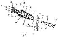
- FIG. 7the position of the endoprosthesis is shown schematically in situ.
- an artificial joint ball 20is shown, which interacts with an artificial joint socket to produce an artificial hip joint.
- the illustration in FIG. 7is only for illustration.
Landscapes
- Health & Medical Sciences (AREA)
- Orthopedic Medicine & Surgery (AREA)
- Cardiology (AREA)
- Oral & Maxillofacial Surgery (AREA)
- Transplantation (AREA)
- Engineering & Computer Science (AREA)
- Biomedical Technology (AREA)
- Heart & Thoracic Surgery (AREA)
- Vascular Medicine (AREA)
- Life Sciences & Earth Sciences (AREA)
- Animal Behavior & Ethology (AREA)
- General Health & Medical Sciences (AREA)
- Public Health (AREA)
- Veterinary Medicine (AREA)
- Prostheses (AREA)
Abstract
Description
Translated fromGermanDie Erfindung betrifft eine Schenkelhalsendoprothese für ein künstliches Hüftgelenk.The invention relates to a femoral neck endoprosthesis for an artificial hip joint.
Zur Behandlung eines distruierten, d. h. zerstörten Hüftgelenkskopf, woraus erhebliche Schmerzempfindungen und gravierende funktionelle Einschränkungen des Gelenks resultieren, haben sich im wesentlichen zwei Therapiemöglichkeiten während der letzten Jahrzehnte durchgesetzt:For the treatment of a distracted, i.e. H. Destroyed femoral head, which results in considerable pain sensations and serious functional restrictions of the joint, two main therapeutic options have prevailed over the past decades:
Zum einen ist es möglich, den Patienten mit einer Orthese zu versorgen, d. h. also mit einem externen Stützapparat. Neben der Tatsache, daß diese Versorgungsmöglichkeit kosmetisch völlig unakzeptabel ist, ist sie auch versorgungstechnisch nur suboptimal.First, it is possible to provide the patient with an orthosis, i.e. H. with an external support device. In addition to the fact that this supply option is cosmetically completely unacceptable, it is also only suboptimal in terms of supply technology.
Als weitere, weitverbreitetere Möglichkeit ist vorgesehen, den Patienten mit einer Endoprothese zu versorgen, namentlich mit einer Hüftstielendoprothese, bei welcher ein Stiel in den zuvor freigeräumten Knochenmarksraum des Femurs eingesetzt wird und dort zementlos oder unter Verwendung eines Zements fixiert wird. An der proximalen Seite weist eine derartige Endoprothese dann die Möglichkeit des Anschlusses einer künstlichen Gelenkkugel vor.Another, more widespread option is to provide the patient with an endoprosthesis, specifically with a hip stem endoprosthesis, in which a stem is inserted into the previously cleared bone marrow space of the femur and is fixed there without cement or using a cement. On the proximal side, such an endoprosthesis then has the possibility of connecting an artificial joint ball.
Gerade die letzte Möglichkeit ist stark in der Patentliteratur vertreten. An dieser Stelle sei nur beispielhaft auf die DE-U-94 12 408 hingewiesen.The last option is particularly well represented in the patent literature. At this point, reference is made to DE-U-94 12 408 only by way of example.
Unter den einen oder anderen der in der Patentliteratur vorgeschlagenen Hüftstielendoprothesen gibt es einige Ansätze, die recht vielversprechend sind im Hinblick auf die Langzeitstabilität im Patientenkörper. Früher oder später jedoch, beispielsweise nach 10 bis 15 Jahren, ist zu beobachten, daß die Endoprothese einem Verschleiß unterworfen ist, welcher zu der Notwendigkeit führt, in einem Revisionseingriff die implantierte Endoprothese zu entfernen und durch eine neue zu ersetzen. Dies ist freilich nicht ganz unproblematisch, da durch die Resektion und Ausräumung des Knochenmarkraumes ein nicht unerheblicher Anteil natürlichen Knochenmaterials bei der Erstimplantation entfernt worden ist. Das einmal entfernte Material fehlt dann unter Umständen bei einem Revisionseingriff. Dies kommt insbesondere dann zum Tragen, wenn die Patienten relativ jung sind, bei denen also von vorn herein davon auszugehen ist, daß sie im Laufe ihres Lebens mindestens einem Revisionseingriff unterworfen werden müssen.Among the one or the other of the hip stem endoprostheses proposed in the patent literature, there are some approaches that are very promising with regard to long-term stability in the patient's body. However, sooner or later, for example after 10 to 15 years, it can be observed that the endoprosthesis is subject to wear, which leads to the need to remove the implanted endoprosthesis in a revision procedure and to replace it with a new one. Of course, this is not without its problems since the resection and removal of the bone marrow space removed a not inconsiderable proportion of natural bone material during the initial implantation. The material once removed may then be missing during a revision intervention. This is particularly important when the patients are relatively young, so it can be assumed from the outset that they will have to undergo at least one revision in the course of their life.
Eine Endoprothese, die mit einer geringfügigeren Resektion natürlichen Knochenmaterials auskommt als die bekannten Hüftstielendoprothesen ist bekannt geworden aus der DE-A-27 24 234. Das darin beschriebene Prothesenteil wird im oberen Bereich eines Femurs, aber unterhalb des Trochanter minors implantiert, ohne daß ein Stiel in den Knochenmarksraum reichen würde. Diese auch als Druckscheibenprothese bezeichnete Prothese greift im wesentlichen mit einer proximalen Druckplatte über die Kortikalis des resezierten Femurs im Bereich des entfernten Hüftgelenkkopfes. Sie wird mit einer Druckplatte, die lateral am Femur anliegt, verspannt, derart, daß alle mechanischen Kräfte zwischen der Endoprothese und dem Femur direkt in die Kortikalschicht des Femurs eingeleitet werden, wodurch eine als unzulässig empfundene mechanische Beanspruchung der Spongiosa vermieden werden soll. Lediglich eine geringe Menge von Knochenzement ist für die Arretierung der Druckscheibe im proximalen Bereich notwendig.An endoprosthesis that requires less resection of natural bone material than the known hip stem endoprosthesis has become known from DE-A-27 24 234. The prosthesis part described therein is implanted in the upper region of a femur, but below the trochanter minor, without a stem would reach into the bone marrow space. This prosthesis, also referred to as a pressure disk prosthesis, essentially engages with a proximal pressure plate over the cortex of the resected femur in the area of the removed hip joint head. It is clamped with a pressure plate, which lies laterally on the femur, in such a way that all mechanical forces between the endoprosthesis and the femur are introduced directly into the cortical layer of the femur, thereby avoiding mechanical stress on the cancellous bone that is perceived as inadmissible should. Only a small amount of bone cement is required to lock the thrust washer in the proximal area.
Der Philosophie dieser Prothese liegt - wie ausgeführt - die Annahme zugrunde, daß die Spongiosa des Femurs möglichst wenig beansprucht werden soll. Dies wird erkauft durch eine extreme Belastung der Kortikalis des Femurs, indem nämlich sämtliche Kräfte darauf abgelastet und darin eingeleitet werden. Dies entspricht nach heutiger Erkenntnis in keiner Weise den natürlichen Belastungsverhältnissen.As stated, the philosophy of this prosthesis is based on the assumption that the cancellous bone of the femur should be strained as little as possible. This is paid for by extreme stress on the cortex of the femur, namely by exerting all the forces on it and introducing it into it. According to current knowledge, this in no way corresponds to the natural stress conditions.
Eine ganz ähnlich wirkende Prothese zeigt im übrigen die WO 89/11837, bei der die Funktion der proximalen Druckplatte gemäß der vorerwähnten Druckschrift wahrgenommen wird durch den speziell ausgebildeten Hüftgelenkkopf, der innenseitig mit einer Ausnehmung versehen ist, an der sich innenseitig der resizierte Femurstumpf unter Druckerzeugung anlegt.A prosthesis with a very similar effect is also shown in WO 89/11837, in which the function of the proximal pressure plate according to the aforementioned document is perceived by the specially designed hip joint head, which is provided on the inside with a recess, on the inside of which the resected femoral stump is under pressure creates.
Zwei Prothesen, bei denen augenscheinlich die Hauptlast von der Spongiosa des Femurknochens aufgenommen werden soll, sind bekanntgeworden aus der FR 26 26 169 A1 und der FR 26 74 122 A1. Bei der erstgenannten Druckschrift der beiden ist vorgesehen, einen proximal einen Steckkonus aufweisenden Gewindebolzen in die Spongiosa einzuschrauben. Dies dürfte innerhalb kürzester Zeit zu schweren Instabilitätsproblemen führen. Bei der zweitgenannten Druckschrift der beiden wird eine einen Steckkonus tragende Platte mittels einer Reihe von Knochenschrauben befestigt, wobei die Knochenschrauben in die Spongiosa reichen. Auch hieraus ergeben sich ernsthafte Stabilitätsfragen, da die Spongiosa von Natur aus im Verhältnis zur Kortikalis des Femurknochens punktuell nur gering belastbar ist.Two prostheses, in which the main load is apparently supposed to be absorbed by the cancellous bone of the femur, have become known from FR 26 26 169 A1 and FR 26 74 122 A1. In the first-mentioned publication of the two, it is provided that a threaded bolt having a plug-in cone proximally is screwed into the cancellous bone. This should lead to serious instability problems within a very short time. In the second-mentioned publication of the two, a plate carrying a plug-in cone is fastened by means of a series of bone screws, the bone screws reaching into the cancellous bone. This also raises serious questions of stability, since the spongiosa is inherently only slightly resilient in relation to the cortex of the femur.
Vor diesem Hintergrund ist es daher die Aufgabe der vorliegenden Erfindung, eine Schenkelhalsendoprothese für ein künstliches Hüftgelenk anzugeben, die sich hinsichtlich der Krafteinleitung in den Femur bei nur relativ geringfügig notwendig werdenden Resektionen von natürlichen Knochenmaterial den natürlichen Verhältnissen erheblich besser anpaßt als die vorerwähnte Prothese.Against this background, it is therefore the object of the present invention to provide a femoral neck endoprosthesis for an artificial hip joint which is only relatively minor with regard to the force application into the femur necessary resections of natural bone material adapt the natural conditions considerably better than the aforementioned prosthesis.
Gelöst wird diese Aufgabe dadurch, daß die Schenkelhalsendoprothese aufweist:
- eine zementlos im oberen Bereich eines Femurs unterhalb des Trochanter minors implantierbare Hülse, mit deren proximalen Ende ein Adapter zur Aufnahme einer künstlichen Gelenkkugel verbindbar ist, wobei die Hülsenaußenseite zumindest teilweise mit einer offenmaschigen dreidimensionalen Raumnetzstruktur belegt ist, sowie
- eine Zugplatte, an der eine Zugschraube anschlagbar ist, die durch eine Durchbohrung im distalen Ende der Hülse in deren Inneres setzbar und mit einem dort vorgesehenen Gewinde verschraubbar ist.
- a cementlessly implantable sleeve in the upper region of a femur below the trochanter minor, with the proximal end of which an adapter for receiving an artificial joint ball can be connected, the outside of the sleeve being at least partially covered with an open-meshed three-dimensional spatial network structure, and
- a tension plate on which a tension screw can be struck, which can be placed in the interior thereof through a through hole in the distal end of the sleeve and screwed with a thread provided there.
Im Gegensatz zu der oben beschriebenen Druckscheibenendoprothese werden die Belastungskräfte nicht in die Kortikalis des Femurs eingeleitet, sondern direkt in die Spongiosa im Inneren des Femurs, nachdem Knochentrapekel während der Einheilungsphase durch die offenmaschige dreidimensionale Raumnetzstruktur auf der Hülsenaußenseite gewachsen ist. Es wird also mit der erfindungsgemäßen Endoprothese genau der Weg beschrieben, welcher in der DE-27 24 234 als nachteilig angesehen worden ist, nämlich die Spongiosa zu belasten. Nach der Einheilphase verhält sich die Hülse der Endoprothese in Nachbildung der natürlichen Verhältnisse aufgrund ihrer quasi Aufhängung an vielen Knochentrapekeln dynamisch, d. h. sie kann abhängig von den jeweiligen Belastungen ausweichende Bewegungen durchaus nachvollziehen und Ausgleichsbewegungen vollführen. Diese Art der Fixation einer Endoprothese entspricht den neueren Erkenntnissen aus der Chirurgie, daß nämlich in einem Röhrenknochen die Hauptlasten nicht von der Kortikalis, sondern von der Spongiosa aufgenommen werden. Es findet mit der erfindungsgemäßen Endoprothese keine Druckbeaufschlagung der Kortikalis statt.In contrast to the pressure disc endoprosthesis described above, the loading forces are not introduced into the cortex of the femur, but directly into the cancellous bone inside the femur, after the bone trapezium has grown during the healing phase through the open-meshed three-dimensional network structure on the outside of the sleeve. The endoprosthesis according to the invention thus describes exactly the way which was considered disadvantageous in DE-27 24 234, namely to stress the cancellous bone. After the healing phase, the sleeve of the endoprosthesis behaves dynamically in replication of the natural conditions due to its quasi suspension on many bone trapezoids, ie it can depend on the Understand evasive movements and carry out compensatory movements. This type of fixation of an endoprosthesis corresponds to the latest findings from surgery, namely that the main loads in a long bone are not absorbed by the cortex but by the cancellous bone. There is no pressurization of the cortex with the endoprosthesis according to the invention.
Zur Vorbereitung der Implantation wird zunächst der zerstörte Femurkopf durch eine subcapitale Resektion entfernt, und zwar im wesentlichen orthograd zur Schenkelhalsachse. Sodann wird mittels eines Fräsers, der eine im wesentlichen gleiche Außenkontur wie die zu implantierende Hülse aufweist, in den Schenkelhals getrieben und eine entsprechende Bohrung oder Aushöhlung in der Spongiosa des Femurs hergestellt. Sodann kann die Hülse in den ausgefrästen Raum im Schenkelhals gesetzt werden. Zur lateralen Festlegung der Hülse ist vorgesehen, von außen an den Femur die erwähnte Zugplatte anzulegen, welche mittels einer Zugschraube mit dem Inneren der Hülse verschraubbar ist. Zu diesem Zweck muß die Kortikalis lateral aufgebohrt werden, so daß die Zugschraube durch die Kortikalis in das Innere der Hülse geführt werden kann, um dort verschraubt zu werden. Die Zugplatte bildet mit der Zugschraube ein im Prinzip bekanntes System der Zuggurtung.To prepare for the implantation, the destroyed femoral head is first removed by subcapital resection, essentially orthogradally to the axis of the femoral neck. Then it is driven into the femoral neck by means of a milling cutter, which has an essentially identical outer contour as the sleeve to be implanted, and a corresponding hole or hollow is made in the cancellous bone of the femur. The sleeve can then be placed in the milled space in the neck of the femur. For lateral fixing of the sleeve, it is provided to apply the mentioned tension plate to the femur from the outside, which can be screwed to the inside of the sleeve by means of a tension screw. For this purpose, the cortex must be drilled out laterally so that the lag screw can be passed through the cortex into the interior of the sleeve in order to be screwed there. The tension plate, together with the tension screw, forms a system of tension strapping that is known in principle.
Der mit dem proximalen Ende der Hülse zu verbindende Adapter kann beliebige geeignete Formen annehmen. Generell ist jedoch darauf zu achten, daß keinerlei Effekte wie bei der Druckscheibe entstehen, wie sie aus der genannten DE-A-27 24 234 bekannt sind.The adapter to be connected to the proximal end of the sleeve can take any suitable form. In general, however, care must be taken to ensure that there are no effects as in the case of the thrust washer as are known from DE-A-27 24 234.
Die Hülse sollte vorteilhafterweise im Querschnitt eine ovalförmige Gestalt haben. Hierdurch wird von vornherein eine Rotationsstabilität der Hülse in der Spongiosa erzielt.The sleeve should advantageously have an oval shape in cross section. This ensures a rotational stability of the sleeve in the cancellous bone from the outset.
Bevorzugt ist im übrigen die Ausbildung der Hülse derart, daß sie sich von ihrem proximalen Ende hin zu ihrem distalen Ende konisch verjüngt. Zum einen entspricht dies der mehr oder weniger konischen Ausbildung des Schenkelhalses, stellt also eine anatomische Adaption dar. Zum anderen wird durch Flächenpressung während der Einheilphase die Kräfteverteilung günstiger wie bei einer Osteosynthese, wenn die Hülse mit der Zugschraube verspannt ist und unter Belastung gesetzt wird, als wenn die Hülse beispielsweise zylindrisch ausgeformt ist.In addition, the sleeve is preferably designed such that it tapers conically from its proximal end to its distal end. On the one hand, this corresponds to the more or less conical design of the femoral neck, that is, it represents an anatomical adaptation. On the other hand, surface pressure during the healing phase makes the force distribution more favorable than in the case of osteosynthesis when the sleeve is tensioned with the lag screw and is placed under load as if the sleeve is cylindrical, for example.
Die Raumnetzstruktur auf der Hülsenaußenseite muß nicht von homogener Maschigkeit sein. Vielmehr wird gemäß einer vorteilhaften Weiterbildung vorgesehen, daß die Raumnetzstruktur auf den nach kaudal und nach kranial (also nach oben und nach unten) weisenden Hülsenaußenseiten grobmaschig mit Maschenweiten zwischen 3 bis 6 mm ausgebildet ist. Dies entspricht den Hauptbelastungsrichtungen der Hülse in dem natürlichen Spongiosabett im Femur und den Trajektorien des Spongiosagewebes des natürlichen Implantat-Lagers im Femur.The spatial network structure on the outside of the sleeve need not be of homogeneous mesh. Rather, according to an advantageous further development, it is provided that the spatial network structure is formed with a wide mesh with mesh sizes between 3 to 6 mm on the outside of the sleeve facing caudally and cranially (ie upwards and downwards). This corresponds to the main directions of loading of the sleeve in the natural cancellous bed in the femur and the trajectories of the cancellous tissue of the natural implant bearing in the femur.
Als eine weitere anatomische Adaption ist vorteilhaft vorgesehen, daß die Raumnetzstruktur in Richtung ventral und dorsal auf der Hülsenaußenseite feinmaschig mit Maschenweiten zwischen 1 bis 2,5 mm ausgebildet ist. Die bereits angesprochene Ovalform des Querschnittes der Hülse ergibt sich bei der Ausbildung der Raumnetzstruktur auf der Hülsenaußenseite mit zwei unterschiedlichen Maschenweiten in diesem Falle von selbst. In diesem Falle wäre die größere Hauptachse des Oval zu suchen in den Bereichen, in denen die grobmaschige Raumnetzstruktur angeordnet ist, die kleinere Nebenachse hingegen bei den kleineren Maschenweiten.As a further anatomical adaptation, it is advantageously provided that the spatial network structure in the ventral and dorsal direction is formed on the outside of the sleeve with a fine mesh with mesh sizes between 1 and 2.5 mm. The oval shape of the cross-section of the sleeve already mentioned arises automatically when the spatial network structure is formed on the outside of the sleeve with two different mesh sizes. In this case, the larger main axis of the oval would have to be sought in the areas in which the coarse-meshed spatial network structure is arranged , however, the smaller minor axis with the smaller mesh sizes.
Bei besonders bevorzugter Ausbildung ist vorgesehen, daß der Adapter für die Gelenkkugel im wesentlichen als Doppelsteckkonus ausgebildet ist mit einem an den beiden Konusbasen umlaufenden Flansch, wobei im proximalen Bereich der Hülse eine dem einen Steckkonus entsprechend ausgebildete konische Steckhülse vorgesehen ist. Zwischen dem einen Steckkonus und der Steckhülse in der Hülse kann also eine konische Klemmverbindung nach bekannten Prinzipien hergestellt werden, wohingegen der andere Steckkonus mit einer Steckhülse in einem künstlichen Gelenkkopf zusammenarbeitet.In a particularly preferred embodiment it is provided that the adapter for the joint ball is essentially designed as a double plug-in cone with a flange running around the two cone bases, in the proximal area the sleeve is provided with a conical plug-in sleeve corresponding to a plug-in cone. A conical clamping connection can therefore be produced between the one plug-in cone and the plug-in sleeve in the sleeve according to known principles, whereas the other plug-in cone cooperates with a plug-in sleeve in an artificial joint head.
Zu bemerken ist hierbei folgendes: der an den beiden Konusbasen umlaufende Flansch dient nicht zur Anlage auf der Resektionsfläche, wie dies beispielsweise bei der proximalen Druckscheibe gemäß der DE-A 27 24 234 der Fall ist. Idealerweise befindet sich zwischen der Resektionsfläche und der dieser zugewandten Seite des Flansches nach Herstellung der konischen Klemmverbindung zur implantierten Hülse ein Spalt von etwa 1 mm Breite. Dieser wird nach der Implantation im Laufe der Zeit von Knochentrapekeln durchwachsen werden, wenn der Flansch auf seine nach außen weisenden Flächen mit einer offenmaschigen dreidimensionalen Raumnetzstruktur belegt ist. Diese Arretierung dient lediglich der Festlegung des Adapters, nicht der Krafteinleitung von Belastungskräften in die Kortikalis des Femurs. Alternativ wäre auch eine Festlegung mittels Schrauben denkbar.The following should be noted here: the flange running around the two cone bases does not serve to rest on the resection surface, as is the case, for example, with the proximal thrust washer according to DE-A 27 24 234. Ideally, there is a gap of approximately 1 mm in width between the resection surface and the side of the flange facing this after the conical clamping connection to the implanted sleeve has been established. Bone trapezoids will grow through this after implantation if the flange is covered with an open-meshed three-dimensional network structure on its outward-facing surfaces. This locking only serves to fix the adapter, not the introduction of load forces into the cortex of the femur. Alternatively, it would also be conceivable to use screws.
Im Falle eines notwendig werdenden Revisionseingriffes paßt in den angesprochenen Spalt das Sägeblatt einer Säge, mit welcher die Knochentrapekel zwischen Adapter, Flansch und Resektionsfläche einfach durchtrennt werden können, so daß der Adapter aus der Hülse mittels eines Abziehwerkzeuges einfach abgezogen werden kann.In the event of a revision intervention becoming necessary, the saw blade of a saw fits into the gap mentioned, with which the bone trapezoids between the adapter, flange and resection surface can be easily severed, so that the adapter can be easily removed from the sleeve by means of a removal tool.
Der Adapter kann durch eine weitere vorteilhafte Maßnahme weiter in seinem konischen Klemmsitz gesichert werden, dadurch, daß im der Hülse zuzuwendenden Steckkonus des Adapters eine Sackbohrung mit Innengewinde vorgesehen ist, mit welchem das Ende der mit einem entsprechenden Gewindeabschnitt versehenen Zugschraube zur Arretierung verschraubbar ist. In diesem Falle greift also die Zugschraube durch das Innere der Hülse weit über das Gewinde hinaus, mit welchem die Zugplatte mit der Hülse mittels der Zugschraube verschraubbar ist, nämlich bis weit hinein in den Bereich der proximalen Steckhülse. Der Steckkonus des Adapters wird in diesem Falle also regelrecht in die konische Klemmhülse der Hülse im Femur durch die Zugschraube hineingezogen und dort unverrückbar festgelegt.The adapter can be further secured in its conical clamping fit by a further advantageous measure, in that a blind bore with an internal thread is provided in the plug-in cone of the adapter facing the sleeve, with which the end of the tension screw provided with a corresponding threaded section can be screwed for locking. In this case, the lag screw extends far through the inside of the sleeve Beyond the thread with which the tension plate can be screwed to the sleeve by means of the tension screw, namely far into the area of the proximal socket. In this case, the plug-in cone of the adapter is literally pulled into the conical clamping sleeve of the sleeve in the femur by the lag screw and immovably fixed there.
Damit es nach Herstellung der Verbindung zwischen Hülse und Zugplatte außen an der Kortikalis des Femurs nicht zu deren Lockerung kommt beim Herstellen der Verbindung zwischen dem Adapter und der Hülse, weist der Gewindeabschnitt am Ende der Zugschraube vorzugsweise eine andere Steigung auf als das Gewinde im Inneren der Hülse. Hierdurch wird ein Selbstkontereffekt erzielt, der eben eine Lockerung der zuerst hergestellten Verbindung unterbindet.So that after the connection between the sleeve and the tension plate on the outside of the cortex of the femur is not loosened when the connection between the adapter and the sleeve is established, the threaded section at the end of the lag screw preferably has a different pitch than the thread inside the Sleeve. In this way, a self-counter effect is achieved, which prevents loosening of the first connection.
Gemäß einer noch weiteren vorteilhaften Ausführungsform der Schenkelhalsendoprothese ist vorgesehen, daß die den Femur zuzuwendenden Flächen der Zugplatte ebenfalls mit einer offenmaschigen dreidimensionalen Raumnetzstruktur belegt sind. Hierdurch erfolgt eine weitere Festlegung des Implantates gegenüber Mikrobewegungen bei Belastungen. Theoretisch könnte zwar auf die Zugplatte nach einem vollständigen Einheilen der Hülse im Spongiosaraum des Femurs verzichtet werden, da diese Fixationsart zu einem äußerst innigen Verbund zwischen Implantat und der Knochenumgebung führt. Überlegungen hinsichtlich einer Langzeitfixation und hinsichtlich der Vermeidung eines unnötigen Risikos können es jedoch erwünscht erscheinen lassen, diese zusätzliche Sicherungsmaßnahme an der Zugplatte vorzusehen.According to yet another advantageous embodiment of the femoral neck endoprosthesis, it is provided that the surfaces of the tension plate facing the femur are also covered with an open-meshed three-dimensional network structure. As a result, the implant is further fixed against micro-movements under stress. Theoretically, the tension plate could be dispensed with after the sleeve has healed completely in the cancellous bone of the femur, since this type of fixation leads to an extremely intimate bond between the implant and the bone environment. However, considerations regarding long-term fixation and avoiding unnecessary risk may make it desirable to provide this additional security measure on the tension plate.
Eine weitere Sicherungsmaßnahme hinsichtlich der Lage der Zugplatte an der lateralen Kortikalis des Femurs ist vorteilhaft dann gegeben, wenn die Zugplatte mit wenigstens einem in Richtung des Femurs weisenden Widerlagers in Form eines Zapfens versehen ist, welcher mit der Zugplatte im wesentlichen denselben Winkel einschließt wie die Hauptachse der Hülse mit der Zugplatte, wobei unter der Achse der Zugplatte deren Hauptachse zu verstehen ist. Das Widerlager wirkt rotationshemmend. Gleichzeitig können etwaige Biegemomente abgelastet werden.A further security measure with regard to the position of the tension plate on the lateral cortex of the femur is advantageously provided if the tension plate is provided with at least one abutment pointing in the direction of the femur in the form of a pin, which includes the tension plate essentially at the same angle as the main axis the sleeve with the tension plate, whereby the axis of the tension plate is to be understood as its main axis. The abutment has an anti-rotation effect. At the same time, any bending moments can be absorbed.
Die Erfindung wird anhand eines Ausführungsbeispiels näher erläutert. Hierbei zeigt:
- Fig. 1
- die Schnittansicht einer im Femur zu implantierenden Hülse der Endoprothese,
- Fig. 2
- die Schnittansicht der Zugplatte der Endoprothese,
- Fig. 3
- die Ansicht der Zugschraube,
- Fig. 4
- die Ansicht in Richtung des Pfeils IV in Fig. 1 auf das proximale Ende der Hülse,
- Fig. 5
- die Ansicht des Adapters zur Aufnahme einer künstlichen Gelenkkugel, teilweise im Schnitt,
- Fig. 6
- die Komponenten der Endoprothese aus
den Figuren 1bis 5 in schematisch dargestellter Lagebeziehung entsprechend der Lagebeziehung bei der Implantation, und - Fig. 7
- die schematisch dargestellte Implantationslage der Endoprothese in dem Schenkelhals eines Femurs.
- Fig. 1
- the sectional view of a sleeve of the endoprosthesis to be implanted in the femur,
- Fig. 2
- the sectional view of the tension plate of the endoprosthesis,
- Fig. 3
- the view of the lag screw,
- Fig. 4
- the view in the direction of arrow IV in Fig. 1 on the proximal end of the sleeve,
- Fig. 5
- the view of the adapter for receiving an artificial joint ball, partly in section,
- Fig. 6
- the components of the endoprosthesis from Figures 1 to 5 in a schematically illustrated positional relationship corresponding to the positional relationship during implantation, and
- Fig. 7
- the schematically illustrated implantation position of the endoprosthesis in the femoral neck of a femur.
Nachfolgend sind dieselben Teile mit denselben Bezugszeichen versehen.In the following, the same parts are provided with the same reference symbols.
In Fig. 1 ist die Hülse 1 der erfindungsgemäßen Endoprothese dargestellt. Die Hülse weist ein proximales Ende 8 und ein distales Ende 6 auf. Im dargestellten Ausführungsbeispiel verläuft die Hülse von ihrem proximalen Ende 8 hin zu ihrem distalen Ende 6 sich konisch verjüngend, was die erwünschten Effekte hinsichtlich der Kraftverteilung bewirkt. Die im Schnitt dargestellte Hülse 1 ist auf ihren Außenflächen vorliegend mit einer offenmaschigen dreidimensionalen Raumnetzstruktur 3 relativ grober Maschenweite (3 bis 6 mm) belegt, und zwar auf den Hülsenaußenseiten, die nach Implantation im Femur nach kaudal und nach kranial zeigen. Dies entspricht in anatomischer Adaption in etwa den Größen der natürlichen Knochentrapekel in diesem im Schenkelhals.In Fig. 1, the
Auf den nach ventral und dorsal weisenden Hülsenaußenseiten (Fig. 4) ist zwar ebenfalls eine offenmaschige dreidimensionale Raumnetzstruktur vorgesehen, jedoch mit wesentlich geringerer Maschenweite, wie dies in Fig. 4 schematisch dargestellt ist. Diese Maschenweiten betragen zwischen 1 bis 2,5 mm.An open-meshed three-dimensional spatial network structure is also provided on the outer and dorsal sleeve sides (FIG. 4), but with a much smaller mesh size, as is shown schematically in FIG. 4. These mesh sizes are between 1 to 2.5 mm.
Im distalen Ende 6 der Hülse 1 ist eine Durchbohrung 5 vorgesehen, der sich in Richtung auf das proximale Ende 8 der Hülse 1 ein Innengewinde 7 anschließt. Dieses geht über in eine zylindrische Bohrung, welche schließlich in einer konischen Klemmhülse 12 am proximalen Ende 8 endet.A
Eine weitere wichtige Komponente der Endoprothese ist die Druckplatte 3, wie sie in beispielhafter Ausführungsform in Fig. 2 in Schnittansicht gezeigt ist. Sie besteht im wesentlichen aus einem plattenförmigen Element, welches eine Durchbohrung 21 aufweist zur Durchführung einer Zugschraube, wie weiter unten noch näher erläutert werden wird.Another important component of the endoprosthesis is the
Sie weist auf ihrer dem Femur zuzuwendenden Fläche eine offenmaschige dreidimensionale Raumnetzstruktur auf, durch welche Knochentrapekel ausgehend von der Kortikalis des Femurs hindurchwachsen, um eine Lagefixierung der Druckplatte 3, aber auch der mit ihr nach der Implantation verbundenen Hülse 1 zu erreichen.On its surface facing the femur, it has an open-mesh, three-dimensional network structure through which bone trapezoids grow starting from the cortex of the femur in order to fix the position of the
Wie ersichtlich, weist die Zugplatte 3 femurwärts ein Widerlager in Form eines Zapfens 18 auf, der hier im selben Winkel geneigt ist wie die Hauptachse der Hülse 1 zur Zugplatte 3.As can be seen, the
Hierdurch wird eine besondere Stabilität hinsichtlich etwaig angreifender Biegemomente erzielt.As a result, a particular stability with regard to any attacking bending moments is achieved.
Fig. 3 zeigt eine Ansicht der Zugschraube 4. Diese weist ausgehend von ihrem Kopf 19 vier Abschnitte auf. Zunächst schließt sich dem Kopf 19 ein zylindrischer Abschnitt 15 mit verringertem Durchmesser gegenüber dem sich daran anschließenden zylindrischen Abschnitt 22 auf. Dieser wiederum folgt ein Gewindeabschnitt 7', dem sich ein weiterer Gewindeabschnitt 14' anschließt. Der Gewindeabschnitt 7' arbeitet mit dem Innengewinde 7 in der Hülse 1 zusammen, wenn nämlich die Zugschraube 4 durch die Zugplatte 3 und die Bohrung in der Kortikalis des Femurs durch die Durchbohrung 5 in der Hülse 1 hindurchgeführt wird. Die Zugschraube 4 zieht sozusagen die Hülse 1 vermittels der Zugplatte 3 nach lateral in ihre Implantationslage. Der durchmesserreduzierte Abschnitt 15 dient zur Feineinstellung der Lage der Zugschraube 4 in der Druckplatte 3 in deren Durchbohrung 21.Fig. 3 shows a view of the
Der distale Gewindeabschnitt 14' der Zugschraube 4 arbeitet mit dem Adapter 2 zusammen, wie er beispielhaft in Fig. 5 teilweise im Schnitt dargestellt ist. Der Adapter 2 besteht vorliegend aus zwei Steckkonen 10 und 10' die voneinander wegragen. Der Steckkonus 10 ist dazu vorgesehen, in die Steckhülse 12 der Hülse gesetzt zu werden und dort unter der Wirkung der entstehenden konischen Klemmverbindung zu verharren. Zur weiteren Lagesicherung ist im Steckkonus 10 eine Sackbohrung 13 mit einem Innengewinde 14 vorgesehen. Mit diesem Innengewinde 14 wird der Gewindeabschnitt 14' der Zugschraube 4 verschraubt.The distal threaded
Mit dem anderen Steckkonus 10' ist in herkömmlicherweise eine künstliche Gelenkkugel verbindbar, ebenfalls unter der Wirkung einer zwischen dem Konus 10' und einer Steckhülse in der Gelenkkugel herzustellenden konischen Klemmverbindung.Conventionally, an artificial joint ball can be connected to the other plug-in cone 10 ', likewise under the action of a conical clamping connection to be produced between the cone 10' and a plug-in sleeve in the joint ball.
Im Bereich der Basen der Konen 10 und 10' des Adapters 2 ist ein umlaufender Flansch 11 ausgebildet. Dieser Flansch dient - wie weiter oben bereits ausgeführt - nicht dazu, eine Ablastung auf der Resektionsfläche des Femurs zu bilden. Dieser Flansch dient lediglich der Rotationssicherung. Zu diesem Zweck sind in dem Flansch 11 einige periphere Bohrungen 23 vorgesehen, durch welche hindurch geeignete Befestigungsmittel (nicht dargestellt) gesetzt werden können, um eine Rotationssicherung durchzuführen. Beispielsweise könnten kleine Schrauben in den Femur durch die Bohrungen 23 hindurchgeführt werden. Alternativ hierzu oder zusätzlich zu dieser Befestigungsmöglichkeit ist vorgesehen, daß die nach außen weisenden Flächen des Flansches 11 mit einer offenmaschigen dreidimensionalen Raumnetzstruktur 16 belegt sind. Nach der Implantation der Endoprothese werden Knochentrapekel von der Resektionsfläche des Femurs in diese Raumstrukturen hineinwachsen bzw. diese durchwachsen und so zu einer Rotationsstabilität führen.A
Bevorzugt erfolgt die Implantation der Endoprothese so, daß zwischen der Resektionsfläche und dem Flansch 11 ein Spalt von beispielsweise 1 mm frei bleibt. Dieser Spalt kann problemlos von den Knochentrapekeln überwundet werden, andererseits jedoch bei einem Revisionseingriff leicht durch ein in diesen Spalt hineinzuführendes Sägeblatt wieder aufgetrennt werden.The endoprosthesis is preferably implanted such that a gap of, for example, 1 mm remains between the resection surface and the
Aus Fig. 6 ergibt sich schematisch der Effekt der Zusammenwirkung der vorbeschriebenen Komponenten der Endoprothese.The effect of the interaction of the above-described components of the endoprosthesis is shown schematically in FIG. 6.
Bei der Implantation befindet sich zwischen der Zugplatte 3 und der Hülse 1 die laterale Kortikalis des Femurs (nicht dargestellt). Die Zugschraube 4 wird durch die Durchbohrung 21 in der Zugplatte 3 und durch die Bohrung in der Kortikalis in die Hülse 1 geführt. Sodann wird der Gewindeabschnitt 7' der Zugschraube 4 mit dem Innengewinde 7 in der Hülse 1 verschraubt, wobei die Hülse 1 dann nach außen (lateral) gezogen wird. Danach kann der Adapter 2 an die Hülse 1 herangebracht werden unter Einsetzen des Steckkonus 10 des Adapters 2 in die Steckhülse 12 in der Hülse 1. Dies geschieht im dargestellten Fall durch ein Einschrauben des Adapters, wobei der Gewindeabschnitt 14' der Zugschraube 4 mit dem Innengewinde 14 in Steckkonus 10 verschraubt wird.During implantation, the lateral cortex of the femur (not shown) is located between the
Eine Rotationsstabilität der Hülse 1 wird von vorn herein durch die ovale Querschnittsform erzielt, welche sich vorliegend aus der Belegung der Außenflächen der Hülse 1 mit offenmaschigen dreidimensionalen Raumnetzstrukturen mit unterschiedlichen Maschenweiten - wie beschrieben - ergibt.A rotational stability of the
Schließlich sei auf Fig. 7 kurz hingewiesen, aus der heraus sich die Lage der Endoprothese in situ schematisch ergibt. Zusätzlich dargestellt ist eine künstliche Gelenkkugel 20, die mit einer künstlichen Gelenkpfanne zusammenwirkt, um ein künstliches Hüftgelenk zu ergeben. Die Darstellung in Fig. 7 dient lediglich der Anschauung.Finally, reference is briefly made to FIG. 7, from which the position of the endoprosthesis is shown schematically in situ. In addition, an artificial
Claims (10)
Translated fromGermanApplications Claiming Priority (2)
| Application Number | Priority Date | Filing Date | Title |
|---|---|---|---|
| DE19601340ADE19601340C1 (en) | 1996-01-16 | 1996-01-16 | Endoprosthesis for neck of femur for artificial hip joint |
| DE19601340 | 1996-01-16 |
Publications (2)
| Publication Number | Publication Date |
|---|---|
| EP0791342A1true EP0791342A1 (en) | 1997-08-27 |
| EP0791342B1 EP0791342B1 (en) | 1999-07-28 |
Family
ID=7782871
Family Applications (1)
| Application Number | Title | Priority Date | Filing Date |
|---|---|---|---|
| EP97100111AExpired - LifetimeEP0791342B1 (en) | 1996-01-16 | 1997-01-07 | Femoral neck endoprosthesis for an artificial hip joint |
Country Status (6)
| Country | Link |
|---|---|
| US (1) | US5766263A (en) |
| EP (1) | EP0791342B1 (en) |
| JP (1) | JPH09289996A (en) |
| AT (1) | ATE182456T1 (en) |
| DE (2) | DE19601340C1 (en) |
| ES (1) | ES2134656T3 (en) |
Cited By (10)
| Publication number | Priority date | Publication date | Assignee | Title |
|---|---|---|---|---|
| WO2000009038A3 (en)* | 1998-08-10 | 2000-09-21 | Novarticulate Bv | Anchoring means for a joint prosthesis or other component |
| WO2003039411A1 (en)* | 2001-11-08 | 2003-05-15 | Eska Implants Gmbh & Co. | Femoral neck endoprosthesis for an artificial hip joint |
| WO2003043544A1 (en)* | 2001-11-22 | 2003-05-30 | Eska Implants Gmbh & Co. | Femoral neck endoprosthesis for an artificial hip joint |
| WO2003043543A1 (en)* | 2001-11-22 | 2003-05-30 | Eska Implants Gmbh & Co. | Femoral neck endoprosthesis for an artificial hip joint |
| EP1332736A1 (en)* | 2002-01-31 | 2003-08-06 | ESKA IMPLANTS GmbH & Co. | Femoral neck endoprosthesis |
| EP1388329A1 (en)* | 2002-08-05 | 2004-02-11 | LIMA Lto SpA | Femoral prosthesis for hip joint |
| EP1499268A4 (en)* | 2002-04-11 | 2005-08-31 | Theodore Crofford | Femoral neck fixation prosthesis |
| ITMI20100307A1 (en)* | 2010-02-25 | 2011-08-26 | Permedica S P A | FEMORAL NECK PROSTHESIS |
| US8801799B2 (en) | 2008-07-24 | 2014-08-12 | Howmedica Osteonics Corp. | Femoral head prosthesis |
| EP3069692A1 (en)* | 2009-07-10 | 2016-09-21 | Kirk Promotion LTD. | Hip joint device |
Families Citing this family (51)
| Publication number | Priority date | Publication date | Assignee | Title |
|---|---|---|---|---|
| SE9600208D0 (en) | 1996-01-19 | 1996-01-19 | Astra Ab | Fixture and prosthesis including the same |
| US5725592A (en)* | 1996-10-29 | 1998-03-10 | Hayes Medical, Inc. | Modular prosthesis having neck component connected to stem component through cavity in body component |
| DE19720493C1 (en) | 1997-05-16 | 1998-10-22 | Eska Implants Gmbh & Co | Femoral neck endoprosthesis for an artificial hip joint |
| DE19725269C2 (en)* | 1997-06-16 | 1999-11-04 | Gamal Baroud | Femoral neck total hip endoprosthesis |
| US6428578B2 (en)* | 1998-03-18 | 2002-08-06 | Sct Incorporated | Modular prosthesis and connector therefor |
| DE19834277C2 (en)* | 1998-07-30 | 2000-08-10 | Gamal Baroud | Femoral neck endoprosthesis for an artificial hip joint |
| US6264699B1 (en)* | 1998-11-23 | 2001-07-24 | Depuy Orthopaedics, Inc. | Modular stem and sleeve prosthesis |
| EP1223894B1 (en)* | 1999-10-06 | 2004-07-21 | Astra Tech Aktiebolag | Implant |
| AU2023301A (en)* | 2000-01-03 | 2001-07-16 | Ory Keynan | Improved prosthesis |
| ES2204234B2 (en)* | 2001-05-16 | 2005-04-16 | Jose Martinez Tetas | PROTECTIVE ADAPTATION DEVICE FOR HIP AND SHOULDER. |
| WO2003026518A1 (en) | 2001-09-27 | 2003-04-03 | Depuy International Limited | Surgical instruments |
| FR2832624B1 (en)* | 2001-11-23 | 2004-08-27 | Science Medecine Sa | FEMALE ROD FOR HIP PROSTHESIS |
| GB0128729D0 (en) | 2001-11-30 | 2002-01-23 | Depuy Int Ltd | Femoral component of hip joint prosthesis |
| US20030163202A1 (en)* | 2002-02-06 | 2003-08-28 | Lakin Ryan C. | Modular resurfacing prosthetic |
| GB0207170D0 (en)* | 2002-03-26 | 2002-05-08 | Mcminn Derek J W | Hip joint prosthesis |
| US7182786B2 (en)* | 2002-04-25 | 2007-02-27 | Zimmer Technology, Inc. | Modular bone implant, tool, and method |
| US6902583B2 (en) | 2002-04-25 | 2005-06-07 | Medicinelodge, Inc. | Tripartite attachment mechanism and method for a modular prosthesis |
| US6875239B2 (en)* | 2002-04-25 | 2005-04-05 | Medicinelodge, Inc. | Modular prosthesis for replacing bone and method |
| US20030204268A1 (en)* | 2002-04-25 | 2003-10-30 | Medicinelodge, Inc. | Binary attachment mechanism and method for a modular prosthesis |
| DE20207913U1 (en)* | 2002-05-22 | 2002-10-02 | ESKA Implants GmbH & Co., 23556 Lübeck | positioning |
| US6866683B2 (en) | 2002-12-13 | 2005-03-15 | Medicine Lodge, Inc. | Modular implant for joint reconstruction and method of use |
| US6887276B2 (en)* | 2002-12-13 | 2005-05-03 | Medicine Lodge, Inc | Modular implant for joint reconstruction and method of use |
| CN100374093C (en)* | 2003-03-13 | 2008-03-12 | 钱本文 | Artificial hip joint device without handle |
| DE10332079B4 (en)* | 2003-07-08 | 2005-09-08 | Eska Implants Gmbh & Co. | Femoral neck endoprosthesis for an artificial hip joint |
| EP1648348B1 (en)* | 2003-07-24 | 2015-06-17 | Tecomet Inc. | Assembled non-random foams |
| GB2411839B (en)* | 2004-03-08 | 2006-11-01 | Biomet Merck Ltd | Prosthesis |
| US7135044B2 (en)* | 2004-03-09 | 2006-11-14 | Howmedics Osteonics Corp. | Modular prosthesis kits |
| GB2419291A (en)* | 2004-10-21 | 2006-04-26 | Biomet Uk Ltd | A femoral head prosthesis |
| US7749259B2 (en)* | 2005-04-08 | 2010-07-06 | Warsaw Orthopedic, Inc. | Slotted screw for use with a vertebral member |
| US8974540B2 (en) | 2006-12-07 | 2015-03-10 | Ihip Surgical, Llc | Method and apparatus for attachment in a modular hip replacement or fracture fixation device |
| US8579985B2 (en) | 2006-12-07 | 2013-11-12 | Ihip Surgical, Llc | Method and apparatus for hip replacement |
| EP2094197B8 (en)* | 2006-12-07 | 2016-03-09 | IHip Surgical, LLC | Apparatus for total hip replacement |
| US8398719B2 (en) | 2009-09-01 | 2013-03-19 | Concept, Design And Development, Llc | Neck sparing total hip implant methods |
| US8470049B2 (en) | 2009-09-01 | 2013-06-25 | Concept, Design And Development, Llc | Neck sparing total hip implant system |
| GB0918484D0 (en)* | 2009-10-22 | 2009-12-09 | Depuy Int Ltd | A medical implant device |
| US9763717B2 (en)* | 2010-03-03 | 2017-09-19 | Luis Mauricio Chiquillo Perez | Multi-tapered implant screw |
| GB201101896D0 (en) | 2011-02-04 | 2011-03-23 | Depuy Ireland Ltd | Arthroplasty plate |
| GB201105243D0 (en) | 2011-03-29 | 2011-05-11 | Depuy Ireland | An implant |
| US10285798B2 (en) | 2011-06-03 | 2019-05-14 | Merit Medical Systems, Inc. | Esophageal stent |
| KR102313261B1 (en) | 2012-06-05 | 2021-10-14 | 메리트 메디컬 시스템즈, 인크. | Esophageal stent |
| US9398928B2 (en)* | 2012-09-28 | 2016-07-26 | DePuy Synthes Products, Inc. | Adjustable height arthroplasty plate |
| EP2964148A4 (en)* | 2013-03-05 | 2016-08-24 | Merit Medical Systems Inc | REINFORCED VALVE |
| US8968409B2 (en) | 2013-03-13 | 2015-03-03 | DePuy Synthes Products, LLC | Orthopaedic implant and method of installing same |
| WO2014150130A1 (en) | 2013-03-15 | 2014-09-25 | Merit Medical Systems, Inc. | Esophageal stent |
| US20140277530A1 (en)* | 2013-03-15 | 2014-09-18 | Smed-Ta/Td, Llc | Fixation of bone implants |
| US9039778B2 (en) | 2013-04-16 | 2015-05-26 | Brian G. Burnikel | Modular, adjustable, prosthetic, hip/shoulder spacer |
| WO2014175986A2 (en) | 2013-04-23 | 2014-10-30 | RevOrtho LLC | A method and system for modular hip resurfacing |
| AU2015297051A1 (en)* | 2014-07-31 | 2017-03-02 | Ossis Limited | Improved implant surface |
| WO2016028795A1 (en)* | 2014-08-18 | 2016-02-25 | RevOrtho LLC | Variable hip resurfacing femoral implant |
| US10945850B2 (en)* | 2018-10-25 | 2021-03-16 | Revision Technologies Llc | Interconnected implants and methods |
| DE102022125997B4 (en) | 2022-04-21 | 2025-04-10 | mechamed GmbH | prosthesis |
Citations (10)
| Publication number | Priority date | Publication date | Assignee | Title |
|---|---|---|---|---|
| EP0099167A1 (en)* | 1982-05-14 | 1984-01-25 | Carbomedics Inc. | Proximal femur implant |
| DE2724234C2 (en) | 1976-06-03 | 1986-01-02 | Arnold Prof.Dr.med. Maienfeld Huggler | Joint end prosthesis |
| EP0230006A1 (en)* | 1986-01-16 | 1987-07-29 | Waldemar Link (GmbH & Co.) | Bone implant |
| DE3607824A1 (en)* | 1986-01-21 | 1987-09-10 | Werner Dr Med Steinleitner | Cementless, rotationally stable compression hip endoprosthesis |
| FR2626169A1 (en) | 1988-01-21 | 1989-07-28 | Hechard Patrick | Hip prosthesis |
| WO1989011837A1 (en) | 1988-06-10 | 1989-12-14 | Albrektsson Bjoern | Hip joint prosthesis |
| FR2674122A1 (en) | 1991-03-21 | 1992-09-25 | Super Patrick | Joint prosthesis, in particular for a joint of the enarthroidal type |
| WO1993001769A1 (en)* | 1991-07-23 | 1993-02-04 | Aktiebolaget Astra | Hip joint prosthesis |
| EP0561263A1 (en)* | 1992-03-14 | 1993-09-22 | ESKA Implants GmbH & Co. | Bone replacement implant |
| DE9412408U1 (en) | 1994-07-27 | 1994-09-22 | Eska Medical GmbH & Co, 23556 Lübeck | Hip handle for an artificial hip joint with a collar |
Family Cites Families (8)
| Publication number | Priority date | Publication date | Assignee | Title |
|---|---|---|---|---|
| US2682265A (en)* | 1951-12-28 | 1954-06-29 | Marie B Collison | Trochanteric plate and artificial femoral head |
| CH638391A5 (en)* | 1979-08-07 | 1983-09-30 | Sulzer Ag | Endoprosthesis for the head of the femur |
| US4612920A (en)* | 1984-11-06 | 1986-09-23 | Zimmer, Inc. | Compression hip screw |
| US4795473A (en)* | 1987-01-09 | 1989-01-03 | Grimes James B | Extramedullary femoral head-neck prosthesis and method of implanting same |
| FR2617706B1 (en)* | 1987-07-08 | 1991-02-15 | Fechant Louis | HIP PROSTHESIS WITH ADJUSTMENT SPACER HAVING A TAPERED PART CONNECTED IN A COMPLEMENTARY ROD CAVITY |
| CH675827A5 (en)* | 1988-10-26 | 1990-11-15 | Sulzer Ag | |
| US4976740A (en)* | 1989-07-14 | 1990-12-11 | Kleiner Jeffrey B | Anchored femoral dome |
| DE4106971C1 (en)* | 1991-03-05 | 1992-03-19 | Eska Medical Luebeck Medizintechnik Gmbh & Co, 2400 Luebeck, De |
- 1996
- 1996-01-16DEDE19601340Apatent/DE19601340C1/ennot_activeExpired - Fee Related
- 1997
- 1997-01-07EPEP97100111Apatent/EP0791342B1/ennot_activeExpired - Lifetime
- 1997-01-07ESES97100111Tpatent/ES2134656T3/ennot_activeExpired - Lifetime
- 1997-01-07DEDE59700273Tpatent/DE59700273D1/ennot_activeExpired - Lifetime
- 1997-01-07ATAT97100111Tpatent/ATE182456T1/ennot_activeIP Right Cessation
- 1997-01-14USUS08/783,476patent/US5766263A/ennot_activeExpired - Fee Related
- 1997-01-16JPJP9005808Apatent/JPH09289996A/enactivePending
Patent Citations (10)
| Publication number | Priority date | Publication date | Assignee | Title |
|---|---|---|---|---|
| DE2724234C2 (en) | 1976-06-03 | 1986-01-02 | Arnold Prof.Dr.med. Maienfeld Huggler | Joint end prosthesis |
| EP0099167A1 (en)* | 1982-05-14 | 1984-01-25 | Carbomedics Inc. | Proximal femur implant |
| EP0230006A1 (en)* | 1986-01-16 | 1987-07-29 | Waldemar Link (GmbH & Co.) | Bone implant |
| DE3607824A1 (en)* | 1986-01-21 | 1987-09-10 | Werner Dr Med Steinleitner | Cementless, rotationally stable compression hip endoprosthesis |
| FR2626169A1 (en) | 1988-01-21 | 1989-07-28 | Hechard Patrick | Hip prosthesis |
| WO1989011837A1 (en) | 1988-06-10 | 1989-12-14 | Albrektsson Bjoern | Hip joint prosthesis |
| FR2674122A1 (en) | 1991-03-21 | 1992-09-25 | Super Patrick | Joint prosthesis, in particular for a joint of the enarthroidal type |
| WO1993001769A1 (en)* | 1991-07-23 | 1993-02-04 | Aktiebolaget Astra | Hip joint prosthesis |
| EP0561263A1 (en)* | 1992-03-14 | 1993-09-22 | ESKA Implants GmbH & Co. | Bone replacement implant |
| DE9412408U1 (en) | 1994-07-27 | 1994-09-22 | Eska Medical GmbH & Co, 23556 Lübeck | Hip handle for an artificial hip joint with a collar |
Cited By (15)
| Publication number | Priority date | Publication date | Assignee | Title |
|---|---|---|---|---|
| WO2000009038A3 (en)* | 1998-08-10 | 2000-09-21 | Novarticulate Bv | Anchoring means for a joint prosthesis or other component |
| WO2003039411A1 (en)* | 2001-11-08 | 2003-05-15 | Eska Implants Gmbh & Co. | Femoral neck endoprosthesis for an artificial hip joint |
| DE10158559C2 (en)* | 2001-11-22 | 2003-10-09 | Eska Implants Gmbh & Co | Femoral neck endoprosthesis for an artificial hip joint |
| WO2003043543A1 (en)* | 2001-11-22 | 2003-05-30 | Eska Implants Gmbh & Co. | Femoral neck endoprosthesis for an artificial hip joint |
| DE10158559A1 (en)* | 2001-11-22 | 2003-06-26 | Eska Implants Gmbh & Co | Femoral neck endoprosthesis for an artificial hip joint |
| WO2003043544A1 (en)* | 2001-11-22 | 2003-05-30 | Eska Implants Gmbh & Co. | Femoral neck endoprosthesis for an artificial hip joint |
| EP1332736A1 (en)* | 2002-01-31 | 2003-08-06 | ESKA IMPLANTS GmbH & Co. | Femoral neck endoprosthesis |
| EP1499268A4 (en)* | 2002-04-11 | 2005-08-31 | Theodore Crofford | Femoral neck fixation prosthesis |
| US7104995B2 (en) | 2002-04-11 | 2006-09-12 | Crofford Theodore W | Method of preparing an acetabulum for receiving a head of a femoral prosthesis |
| US7695474B2 (en) | 2002-04-11 | 2010-04-13 | Howmedica Osteonics Corp. | Method of preparing an acetabulum for receiving a head of a femoral prosthesis |
| EP1388329A1 (en)* | 2002-08-05 | 2004-02-11 | LIMA Lto SpA | Femoral prosthesis for hip joint |
| US8801799B2 (en) | 2008-07-24 | 2014-08-12 | Howmedica Osteonics Corp. | Femoral head prosthesis |
| EP3069692A1 (en)* | 2009-07-10 | 2016-09-21 | Kirk Promotion LTD. | Hip joint device |
| ITMI20100307A1 (en)* | 2010-02-25 | 2011-08-26 | Permedica S P A | FEMORAL NECK PROSTHESIS |
| WO2011104003A1 (en)* | 2010-02-25 | 2011-09-01 | Permedica S.P.A. | Femoral neck prosthesis |
Also Published As
| Publication number | Publication date |
|---|---|
| EP0791342B1 (en) | 1999-07-28 |
| ATE182456T1 (en) | 1999-08-15 |
| US5766263A (en) | 1998-06-16 |
| DE19601340C1 (en) | 1997-06-05 |
| ES2134656T3 (en) | 1999-10-01 |
| DE59700273D1 (en) | 1999-09-02 |
| JPH09289996A (en) | 1997-11-11 |
Similar Documents
| Publication | Publication Date | Title |
|---|---|---|
| DE19601340C1 (en) | Endoprosthesis for neck of femur for artificial hip joint | |
| EP0079441B1 (en) | Endoprosthesis for replacement of rod-shaped bones | |
| AT398529B (en) | ENDOPROTHESIS, ESPECIALLY THE HIP JOINT | |
| EP1959871B1 (en) | Facet joint prosthesis | |
| DE60224470T2 (en) | Hüftimplantataufbau | |
| EP0792127B1 (en) | Joint prosthesis | |
| DE69808438T2 (en) | hip prosthesis | |
| EP0592897B1 (en) | Modular shaft for a hip prothesis | |
| DE69322863T2 (en) | JOINT PROSTHESIS | |
| DE68912994T2 (en) | Prosthesis. | |
| EP1133267B1 (en) | Reinforcement endoprosthesis | |
| DE19722389C2 (en) | Modular knee arthrodesis implant | |
| EP0390883B1 (en) | Hip-joint prosthesis and use thereof | |
| EP0928172A1 (en) | Shankless knee joint endoprosthesis | |
| EP0878176B1 (en) | Femoral neck endoprosthesis for an artificial hip joint | |
| DE3336005C2 (en) | ||
| DE19610741C1 (en) | Internal locking prosthesis for artificial hip-joint | |
| DE20007950U1 (en) | Femoral neck prosthesis | |
| EP1446076B1 (en) | Femoral neck endoprosthesis for an artificial hip joint | |
| EP2846738B1 (en) | Reinforcement implant for a long bone, in particular the femur | |
| EP2689749A1 (en) | Clip-on module for a long shaft prosthetic | |
| EP1559383A2 (en) | Set for constructing a transcutaneous implant | |
| DE10130366A1 (en) | Hip joint endoprothesis consists of a ball section with inner and outer sections and a shaft which is connected to it | |
| AT502137B1 (en) | PRIMARY CHAIR FOR A HIP JOINT PROSTHESIS | |
| DE202019005511U1 (en) | Bone anchoring device for pedicle access |
Legal Events
| Date | Code | Title | Description |
|---|---|---|---|
| PUAI | Public reference made under article 153(3) epc to a published international application that has entered the european phase | Free format text:ORIGINAL CODE: 0009012 | |
| 17P | Request for examination filed | Effective date:19970521 | |
| AK | Designated contracting states | Kind code of ref document:A1 Designated state(s):AT CH DE ES FR GB IT LI NL | |
| 17Q | First examination report despatched | Effective date:19980126 | |
| GRAG | Despatch of communication of intention to grant | Free format text:ORIGINAL CODE: EPIDOS AGRA | |
| GRAG | Despatch of communication of intention to grant | Free format text:ORIGINAL CODE: EPIDOS AGRA | |
| GRAH | Despatch of communication of intention to grant a patent | Free format text:ORIGINAL CODE: EPIDOS IGRA | |
| GRAH | Despatch of communication of intention to grant a patent | Free format text:ORIGINAL CODE: EPIDOS IGRA | |
| GRAA | (expected) grant | Free format text:ORIGINAL CODE: 0009210 | |
| AK | Designated contracting states | Kind code of ref document:B1 Designated state(s):AT CH DE ES FR GB IT LI NL | |
| REF | Corresponds to: | Ref document number:182456 Country of ref document:AT Date of ref document:19990815 Kind code of ref document:T | |
| REG | Reference to a national code | Ref country code:CH Ref legal event code:EP | |
| REG | Reference to a national code | Ref country code:CH Ref legal event code:NV Representative=s name:DIPL.-ING. ETH H. R. WERFFELI PATENTANWALT | |
| GBT | Gb: translation of ep patent filed (gb section 77(6)(a)/1977) | Effective date:19990729 | |
| REF | Corresponds to: | Ref document number:59700273 Country of ref document:DE Date of ref document:19990902 | |
| ITF | It: translation for a ep patent filed | ||
| REG | Reference to a national code | Ref country code:ES Ref legal event code:FG2A Ref document number:2134656 Country of ref document:ES Kind code of ref document:T3 | |
| ET | Fr: translation filed | ||
| PLBE | No opposition filed within time limit | Free format text:ORIGINAL CODE: 0009261 | |
| STAA | Information on the status of an ep patent application or granted ep patent | Free format text:STATUS: NO OPPOSITION FILED WITHIN TIME LIMIT | |
| 26N | No opposition filed | ||
| REG | Reference to a national code | Ref country code:GB Ref legal event code:IF02 | |
| PGFP | Annual fee paid to national office [announced via postgrant information from national office to epo] | Ref country code:GB Payment date:20041229 Year of fee payment:9 | |
| PGFP | Annual fee paid to national office [announced via postgrant information from national office to epo] | Ref country code:NL Payment date:20050118 Year of fee payment:9 | |
| PGFP | Annual fee paid to national office [announced via postgrant information from national office to epo] | Ref country code:FR Payment date:20050119 Year of fee payment:9 | |
| PGFP | Annual fee paid to national office [announced via postgrant information from national office to epo] | Ref country code:ES Payment date:20050124 Year of fee payment:9 | |
| PG25 | Lapsed in a contracting state [announced via postgrant information from national office to epo] | Ref country code:GB Free format text:LAPSE BECAUSE OF NON-PAYMENT OF DUE FEES Effective date:20060107 | |
| PG25 | Lapsed in a contracting state [announced via postgrant information from national office to epo] | Ref country code:ES Free format text:LAPSE BECAUSE OF NON-PAYMENT OF DUE FEES Effective date:20060109 | |
| PGFP | Annual fee paid to national office [announced via postgrant information from national office to epo] | Ref country code:AT Payment date:20060123 Year of fee payment:10 | |
| PGFP | Annual fee paid to national office [announced via postgrant information from national office to epo] | Ref country code:CH Payment date:20060124 Year of fee payment:10 | |
| PG25 | Lapsed in a contracting state [announced via postgrant information from national office to epo] | Ref country code:FR Free format text:LAPSE BECAUSE OF NON-PAYMENT OF DUE FEES Effective date:20060131 | |
| PGFP | Annual fee paid to national office [announced via postgrant information from national office to epo] | Ref country code:IT Payment date:20060131 Year of fee payment:10 | |
| PG25 | Lapsed in a contracting state [announced via postgrant information from national office to epo] | Ref country code:NL Free format text:LAPSE BECAUSE OF NON-PAYMENT OF DUE FEES Effective date:20060801 | |
| GBPC | Gb: european patent ceased through non-payment of renewal fee | Effective date:20060107 | |
| NLV4 | Nl: lapsed or anulled due to non-payment of the annual fee | Effective date:20060801 | |
| REG | Reference to a national code | Ref country code:FR Ref legal event code:ST Effective date:20060929 | |
| PG25 | Lapsed in a contracting state [announced via postgrant information from national office to epo] | Ref country code:LI Free format text:LAPSE BECAUSE OF NON-PAYMENT OF DUE FEES Effective date:20070131 Ref country code:CH Free format text:LAPSE BECAUSE OF NON-PAYMENT OF DUE FEES Effective date:20070131 | |
| REG | Reference to a national code | Ref country code:ES Ref legal event code:FD2A Effective date:20060109 | |
| REG | Reference to a national code | Ref country code:CH Ref legal event code:PL | |
| PG25 | Lapsed in a contracting state [announced via postgrant information from national office to epo] | Ref country code:AT Free format text:LAPSE BECAUSE OF NON-PAYMENT OF DUE FEES Effective date:20070107 | |
| PG25 | Lapsed in a contracting state [announced via postgrant information from national office to epo] | Ref country code:IT Free format text:LAPSE BECAUSE OF NON-PAYMENT OF DUE FEES Effective date:20070107 | |
| PGFP | Annual fee paid to national office [announced via postgrant information from national office to epo] | Ref country code:DE Payment date:20100108 Year of fee payment:14 | |
| REG | Reference to a national code | Ref country code:DE Ref legal event code:R081 Ref document number:59700273 Country of ref document:DE Owner name:ORTHODYNAMICS GMBH, DE Free format text:FORMER OWNER: ESKA IMPLANTS GMBH & CO.KG, 23556 LUEBECK, DE Effective date:20110707 | |
| REG | Reference to a national code | Ref country code:DE Ref legal event code:R119 Ref document number:59700273 Country of ref document:DE Effective date:20110802 | |
| PG25 | Lapsed in a contracting state [announced via postgrant information from national office to epo] | Ref country code:DE Free format text:LAPSE BECAUSE OF NON-PAYMENT OF DUE FEES Effective date:20110802 |