EP0790175B1 - Bicycle shift levers which surround a handlebar - Google Patents
Bicycle shift levers which surround a handlebarDownload PDFInfo
- Publication number
- EP0790175B1 EP0790175B1EP97300916AEP97300916AEP0790175B1EP 0790175 B1EP0790175 B1EP 0790175B1EP 97300916 AEP97300916 AEP 97300916AEP 97300916 AEP97300916 AEP 97300916AEP 0790175 B1EP0790175 B1EP 0790175B1
- Authority
- EP
- European Patent Office
- Prior art keywords
- pivoting
- lever
- operating
- control body
- operating body
- Prior art date
- Legal status (The legal status is an assumption and is not a legal conclusion. Google has not performed a legal analysis and makes no representation as to the accuracy of the status listed.)
- Expired - Lifetime
Links
- 238000006073displacement reactionMethods0.000claimsdescription25
- 230000033001locomotionEffects0.000claimsdescription24
- 230000005540biological transmissionEffects0.000claimsdescription19
- 230000000694effectsEffects0.000claimsdescription9
- 230000008878couplingEffects0.000claimsdescription4
- 238000010168coupling processMethods0.000claimsdescription4
- 238000005859coupling reactionMethods0.000claimsdescription4
- 210000003811fingerAnatomy0.000description30
- 230000007246mechanismEffects0.000description27
- 210000003813thumbAnatomy0.000description7
- 230000001953sensory effectEffects0.000description5
- 238000010276constructionMethods0.000description4
- 238000005452bendingMethods0.000description2
- 238000002372labellingMethods0.000description2
- 238000004873anchoringMethods0.000description1
- 210000004247handAnatomy0.000description1
- 230000004048modificationEffects0.000description1
- 238000012986modificationMethods0.000description1
- 125000006850spacer groupChemical group0.000description1
Images


Classifications
- B—PERFORMING OPERATIONS; TRANSPORTING
- B62—LAND VEHICLES FOR TRAVELLING OTHERWISE THAN ON RAILS
- B62M—RIDER PROPULSION OF WHEELED VEHICLES OR SLEDGES; POWERED PROPULSION OF SLEDGES OR SINGLE-TRACK CYCLES; TRANSMISSIONS SPECIALLY ADAPTED FOR SUCH VEHICLES
- B62M25/00—Actuators for gearing speed-change mechanisms specially adapted for cycles
- B62M25/02—Actuators for gearing speed-change mechanisms specially adapted for cycles with mechanical transmitting systems, e.g. cables, levers
- B62M25/04—Actuators for gearing speed-change mechanisms specially adapted for cycles with mechanical transmitting systems, e.g. cables, levers hand actuated
- B—PERFORMING OPERATIONS; TRANSPORTING
- B62—LAND VEHICLES FOR TRAVELLING OTHERWISE THAN ON RAILS
- B62K—CYCLES; CYCLE FRAMES; CYCLE STEERING DEVICES; RIDER-OPERATED TERMINAL CONTROLS SPECIALLY ADAPTED FOR CYCLES; CYCLE AXLE SUSPENSIONS; CYCLE SIDE-CARS, FORECARS, OR THE LIKE
- B62K23/00—Rider-operated controls specially adapted for cycles, i.e. means for initiating control operations, e.g. levers, grips
- B62K23/02—Rider-operated controls specially adapted for cycles, i.e. means for initiating control operations, e.g. levers, grips hand actuated
- B62K23/06—Levers
- Y—GENERAL TAGGING OF NEW TECHNOLOGICAL DEVELOPMENTS; GENERAL TAGGING OF CROSS-SECTIONAL TECHNOLOGIES SPANNING OVER SEVERAL SECTIONS OF THE IPC; TECHNICAL SUBJECTS COVERED BY FORMER USPC CROSS-REFERENCE ART COLLECTIONS [XRACs] AND DIGESTS
- Y10—TECHNICAL SUBJECTS COVERED BY FORMER USPC
- Y10T—TECHNICAL SUBJECTS COVERED BY FORMER US CLASSIFICATION
- Y10T74/00—Machine element or mechanism
- Y10T74/20—Control lever and linkage systems
- Y10T74/20012—Multiple controlled elements
- Y10T74/20018—Transmission control
- Y10T74/20037—Occupant propelled vehicle
- Y10T74/20043—Transmission controlled by flexible cable
- Y—GENERAL TAGGING OF NEW TECHNOLOGICAL DEVELOPMENTS; GENERAL TAGGING OF CROSS-SECTIONAL TECHNOLOGIES SPANNING OVER SEVERAL SECTIONS OF THE IPC; TECHNICAL SUBJECTS COVERED BY FORMER USPC CROSS-REFERENCE ART COLLECTIONS [XRACs] AND DIGESTS
- Y10—TECHNICAL SUBJECTS COVERED BY FORMER USPC
- Y10T—TECHNICAL SUBJECTS COVERED BY FORMER US CLASSIFICATION
- Y10T74/00—Machine element or mechanism
- Y10T74/20—Control lever and linkage systems
- Y10T74/20012—Multiple controlled elements
- Y10T74/20018—Transmission control
- Y10T74/2014—Manually operated selector [e.g., remotely controlled device, lever, push button, rotary dial, etc.]
- Y—GENERAL TAGGING OF NEW TECHNOLOGICAL DEVELOPMENTS; GENERAL TAGGING OF CROSS-SECTIONAL TECHNOLOGIES SPANNING OVER SEVERAL SECTIONS OF THE IPC; TECHNICAL SUBJECTS COVERED BY FORMER USPC CROSS-REFERENCE ART COLLECTIONS [XRACs] AND DIGESTS
- Y10—TECHNICAL SUBJECTS COVERED BY FORMER USPC
- Y10T—TECHNICAL SUBJECTS COVERED BY FORMER US CLASSIFICATION
- Y10T74/00—Machine element or mechanism
- Y10T74/20—Control lever and linkage systems
- Y10T74/20207—Multiple controlling elements for single controlled element
- Y10T74/20256—Steering and controls assemblies
- Y10T74/20268—Reciprocating control elements
- Y10T74/2028—Handle bar type
- Y10T74/20287—Flexible control element
- Y—GENERAL TAGGING OF NEW TECHNOLOGICAL DEVELOPMENTS; GENERAL TAGGING OF CROSS-SECTIONAL TECHNOLOGIES SPANNING OVER SEVERAL SECTIONS OF THE IPC; TECHNICAL SUBJECTS COVERED BY FORMER USPC CROSS-REFERENCE ART COLLECTIONS [XRACs] AND DIGESTS
- Y10—TECHNICAL SUBJECTS COVERED BY FORMER USPC
- Y10T—TECHNICAL SUBJECTS COVERED BY FORMER US CLASSIFICATION
- Y10T74/00—Machine element or mechanism
- Y10T74/20—Control lever and linkage systems
- Y10T74/20396—Hand operated
- Y10T74/20402—Flexible transmitter [e.g., Bowden cable]
- Y10T74/2042—Flexible transmitter [e.g., Bowden cable] and hand operator
- Y10T74/20438—Single rotatable lever [e.g., for bicycle brake or derailleur]
- Y—GENERAL TAGGING OF NEW TECHNOLOGICAL DEVELOPMENTS; GENERAL TAGGING OF CROSS-SECTIONAL TECHNOLOGIES SPANNING OVER SEVERAL SECTIONS OF THE IPC; TECHNICAL SUBJECTS COVERED BY FORMER USPC CROSS-REFERENCE ART COLLECTIONS [XRACs] AND DIGESTS
- Y10—TECHNICAL SUBJECTS COVERED BY FORMER USPC
- Y10T—TECHNICAL SUBJECTS COVERED BY FORMER US CLASSIFICATION
- Y10T74/00—Machine element or mechanism
- Y10T74/20—Control lever and linkage systems
- Y10T74/20576—Elements
- Y10T74/20732—Handles
- Y10T74/2078—Handle bars
- Y10T74/20822—Attachments and accessories
Definitions
- the present inventionis directed to a bicycle shifting device which operates a shifter via a shifter cable, and specifically concerns a device in which a take-up body that takes up the shifter cable is caused to rotate in the take-up direction by means of a first shift lever which freely returns to a home position, and is caused to rotate in the pay-out direction by means of a second shift lever which freely returns to a separate home position.
- a bicycle shifter operating device equipped with first and second shift levers such as those described aboveis known (for example) from Japanese Patent Application Kokai No. 4-183696.
- the first shift lever and the second shift levercan pivot about a common pivoting axis wherein the operating direction of the first shift lever is clockwise and the operating direction of the second shift lever is counterclockwise.
- the first shift leveris arranged so that it can be operated by the thumb of the hand gripping the handlebar
- the second shift leveris arranged so that it can be operated by the index finger of the hand gripping the handlebar.
- the first and second leverstypically pivot about an axis that is perpendicular to the handlebar.
- shifting devicesAnother ergonomic consideration of shifting devices is the sensory feedback provided by the shifting device.
- Some cyclistsprefer a shifting device which provide very different sensory feedback between the upshifting and downshifting operations.
- a shifting device with two pivoting leversdoes not provide sufficient sensory difference between the upshifting and downshifting operation, since both levers pivot.
- shifting devices constructed with a rotating sleevesince both upshifting and downshifting is performed by rotating the sleeve.
- a bicycle shifter operating devicein which the first shift lever is operated by pivoting and the second shift lever is operated by means of a button in order to achieve a clear sensory difference between the shifter cable take-up operation and the shifter cable pay-out operation is known from British Patent Disclosure No. 2,169,065 (corresponding to Japanese Patent Application Kokai No. 61-222889).
- a pivoting leveris used when the take-up body is to be rotated in the direction which takes up the shifter cable.
- the present inventionprovides a bicycle shifter operating device for operating a shifter via a transmission element comprising:
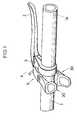
- FIG. 1is a perspective view showing a particular embodiment of a shifter operating mechanism according to the present invention.
- a brake bracket 3which pivotally supports a brake lever 2 is fastened in place adjacent to a grip 1a formed on the handlebar 1 of a bicycle.
- a shifter operating device 5which pulls and releases a shifter cable 4 is attached to the side surface of this brake bracket 3.
- the arm-shaped sliding operating body 20 of the shifter operating device 5extends above the handlebar 1, and the pivoting operating body 30 of the shifter operating device 5 extends beneath the handlebar 1, so that operation of both levers is possible with the thumb of the hand gripping the handlebar grip 1a.
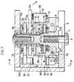
- the shifter operating device 5includes a supporting shaft 8 which is rigidly fastened by means of an attachment bolt 7 to a bracket 6 which, in turn, may be formed as an integral part of the brake bracket 3.
- a take-up body 70is attached to the base end of supporting shaft 8, and a positioning mechanism 80 is built into a recessed area 71 formed in take-up body 70.
- a first ratchet mechanism 50used as a first transmission means, transmits the displacement of a sliding operating body 20 to the take-up body 70 to cause the rotation of the take-up body 70 in one direction
- a second ratchet mechanism 60used as a second transmission means, transmits the displacement of a pivoting operating body 30 to the take-up body 70 to cause the rotation of the take-up body 70 in the other direction.
- the sliding operating body 20is equipped with a first arm part 21 which forms the main part of the sliding operating body, a first finger contact part 22 which is formed on the tip of the first arm part 21 in order to allow finger operation, a rotating plate 23 (constituting a root part) which is supported on the supporting shaft 8 so that the plate 23 can rotate about the supporting shaft 8, and a pair of link members 26 which link the first arm part 21 with a projecting part 23a of the rotating plate 23 via pivot pins 24 and 25.
- the pivoting operating body (30)is equipped with a second arm part 31 which forms the main part of the pivoting operating body, a second finger contact part 32 which is formed on the tip of the second arm part 31 in order to allow finger operation, and a rotating plate 33 (constituting a root part) which is supported on the supporting shaft 8 so that the plate 33 can rotate about the supporting shaft 8.
- the first ratchet mechanism 50is equipped with a first feeding pawl 51 which is rotatably attached to the pivot pin 24, a first ratchet part 72 which is formed on the outer circumferential surface of the take-up body 70 so that the ratchet part 72 can engage with the feeding pawl 51, and a spring 52 which drives the first feeding pawl 51 in the direction of engagement.
- the second ratchet mechanism 60is quipped with a second feeding pawl 61 which is rotatably attached to a pivot pin 34 installed on the transitional part 33a between the rotating plate 33 and second arm part 31, a second ratchet part 73 which is formed on the outer circumferential surface of the take-up body 70 so that the ratchet part 73 can engage with the feeding pawl 61, and a spring 62 which drives the second feeding pawl 61 in the direction of engagement.
- the take-up body 70is equipped with a drum part which is constructed so that the inner wire 4a of the shifter cable 4 from a shifter (not shown) on the front or rear of the bicycle is taken up along a wire groove 74. By rotating in the forward direction or reverse direction with respect to the supporting shaft 8, the take-up body 70 takes up or pays out the inner wire 4a.
- the first arm part 21 of the sliding operating body 20is linked with the rotating plate 23 by means of the link members 26 and pivot pin 24. Both ends of the pivot pin 24 are extended, and the extended end portions are inserted into grooves 6a formed in the bracket 6. Accordingly, the first arm part 21 is guided by the grooves 6a, and performs a linear sliding motion. As a result of this sliding motion, the rotating member 23, which is pivotably fit over the supporting shaft 8 via a bush 9a, is caused to pivot about the axial center X of the supporting shaft 8.
- the rotating plate 23has a projection 23b which projects radially outward.
- This projection 23bis designed so that it will contact one side surface of a stopper 10a formed by bending a circumferential projecting part 10a of a cam member 10 which is attached to the supporting shaft 8 in the pivoting track of the projection 23b.
- Rotating plate 23is driven by a return spring 11a in the direction which causes contact between the projection 23b and the stopper 10a.
- the position in which the projection 23b and stopper 10a are in contact with each otherconstitutes the home position HP1 of the rotating plate 23 and the sliding operating body 20.
- the sliding operating body 20is operated with this home position as a starting point.
- the second arm part 31, second finger contact part 32 and rotating plate 33(which constitutes the second root part) are formed as an integral unit, and the rotating plate 33 is pivotably fit over the supporting shaft 8 via a bush 9b. Accordingly, when the second finger contact part 32 is pressed, the rotating plate 33 pivots about the axial center X of the supporting shaft 8.
- the transitional part between the second arm part 31 and the rotating plate 33, I.e., the root of the second arm part 31,is designed so that it contacts the other side surface of the stopper 10a formed by a portion of the cam member 10 in the pivoting track of the root of the second arm part 31.
- the second arm part 31is driven by a return spring 11b in the direction which causes contact between the second arm part 31 and the stopper 10a.
- the position in which the second arm part 31 and stopper 10a are in contact with each otherconstitutes the home position HP2 of the rotating plate 33 and operating body 30.
- the pivoting operating body 30is operated with this home position as a starting point.
- the first and second finger contact parts 22,32can easily be set in positions which are convenient for the fingers of the hand gripping the handlebar grip, since the finger contact parts 22,32 are located in positions distant from the take-up body. Furthermore, if the system is constructed so that the first finger contact part 22 is displaced in substantially the same plane as the plane of the pivoting track of the second finger contact part 32 , I e., if the first finger contact part 22 is positioned on a line constituting a direct extension of the pivoting range of the second finger contact part 32 , then the two operating bodies can be operated by a bending motion and a pivoting motion of the thumb of the hand gripping the handlebar grip.
- the tip of the first feeding pawl 51rides up on a first cam part 10b formed on the circumference of the cam member 10. Accordingly, as a result of being pushed upward by the first cam part 10b of the cam member 10, the first feeding pawl 51 is released from the first ratchet part 72, so that rotation of the take-up body 70 by the pivoting operating body 30 is made possible.
- the first feeding pawl 51is released from the first cam part 10b and is caused to pivot toward the first ratchet part 72 by the driving force of the first pawl spring 52.
- the feeding pawl 51engages with one of the plurality of ratchet teeth of the first ratchet part 72, thus coupling the sliding operating body 20 and the take-up body 70 so that the bodies rotate as a unit.
- the sliding operating body 20moves from a prescribed shift operating position to the home position HP1
- the first feeding pawl 51is pushed upward by the shape of the ratchet teeth of the first ratchet part 72, so that the engagement of the first feeding pawl 51 with the first ratchet part 72 is automatically released.
- the first ratchet mechanism 50transmits the sliding displacement of the sliding operating body 20 to the take-up body 70 to cause a take-up rotational operation of the take-up body 70. Thereafter, when the sliding operating body 20 slides from the shift operating position to the home position HP1, the engagement between the first feeding pawl 51 and the first ratchet part 72 is released, thus making it possible for the sliding operating body 20 to return to the home position HP1 while the take-up body 70 remains in a prescribed shift position.
- the tip of the second feeding pawl 61rides up on a second cam part 10c formed on the circumference of the cam member 10. Accordingly, as a result of being pushed upward by the second cam part 10c of the cam member 10, the second feeding pawl 61 is released from the second ratchet part 73, so that rotation of the take-up body 70 by the sliding operating body 20 is made possible.
- the pivoting operating body 30pivots in the direction indicated by the arrow from the home position HP2
- the second feeding pawl 61is released from the second cam part 10c and is caused to pivot toward the second ratchet part 73 by the driving force of the second pawl spring 62.
- the feeding pawl 61engages with one of the plurality of ratchet teeth of the second ratchet part 73, thus coupling the pivoting operating body 30 and the take-up body 70 so that the bodies rotate as a unit.
- the pivoting operating body 30pivots from a prescribed shift operating position to the home position HP2
- the second feeding pawl 61is pushed upward by the shape of the ratchet teeth of the second ratchet part 73, so that the engagement of the second feeding pawl 61 with the ratchet part 72 is automatically released.
- the second ratchet mechanism 60transmits the pivoting displacement of the pivoting operating body 30 to the take-up body 70 to cause a pay out rotational operation of the take-up body 70. Thereafter, when the pivoting operating body 30 pivots from the shift operating position to the home position HP2, the engagement between the second feeding pawl 61 and the second ratchet part 73 is released, thus making it possible for the pivoting operating body 30 to return to the home position HP2 while the take-up body 70 remains in a prescribed shift position.
- the positioning mechanism 80is constructed from a first positioning plate 81 and second positioning plate 82 which are fit over the supporting shaft 8 inside the take-up body 70, and a pair of coned disk springs 83 which are fit over the supporting shaft 8 between the first positioning plate 81 and the bottom surface of a recessed part 71.
- a circular through-hole 81ais formed in the central portion of the first positioning plate 81, and spline projections 81b are formed on the circumference of the first positioning plate 81.
- This through-hole 81ais used to fit the first positioning plate 81 over the supporting shaft 8, and the spline projections 81b are inserted into the spaces between a plurality of radially oriented projecting parts formed on the inside circumferential surface of a tube-form part 75 which forms the recessed part 71 of the take-up body 70.
- the first positioning plate 81can slide along the supporting shaft 8 and rotates as a unit with the take-up body 70.
- the second positioning plate 82is spline-engaged with the supporting shaft 8 by means of a spline hole 82a, and the second positioning plate 82 is positioned with respect to its upper limit by means of a tightening nut 84 via a spacer 85.
- Coned disk springs 83drive the first positioning plate 81 toward the second positioning plate 82 so that a plurality of projecting strips 81c formed on the first positioning plate 81 respectively enter a plurality of recessed grooves 82b formed in the second positioning plate 82.
- the positioning mechanism 80is in this engaged state, the second positioning plate 82 fastened to the supporting shaft 8 stops the rotation of the take-up body 70 via the first positioning plate 81.
- the first positioning plate 81slides away from the second positioning plate 82 against the force of the coned disk springs 83, so that the engaged state is switched to a disengaged state in which the projecting strips 81c slip out of the recessed grooves 82b formed in the second positioning plate 82, thus allowing rotation of the take-up body 70.
- the positioning mechanism 80assumes a disengaged state so that the take-up body 70 can rotate. Afterward, the positioning mechanism 80 positions the take-up body 70 in the prescribed shift position by again switching from a disengaged state to an engaged state.
- the first ratchet mechanism 50transmits the sliding displacement of the sliding operating body 20 as a rotational displacement of the take-up body 70.
- the positioning mechanism 80assumes a disengaged state, and the take-up body 70 rotates toward the take-up side so that the inner wire 4a is taken up.
- the take-up body 70reaches a prescribed shift position, the sliding operation of the sliding operating body 20 is stopped.
- the take-up body 70is in a new shift position which is the target position of the shifting operation, so that the take-up of a prescribed length of the inner wire 4a is completed.
- the positioning mechanism 80switches from a disengaged state to an engaged state, so that the take-up body 70 is maintained in the new shift position.
- the sliding operating body 20is automatically returned to its home position HP1 by the return spring 11a.
- the first finger contact part 22 and second finger contact part 32are again located adjacent to each other as shown in Figure 3.
- the second ratchet mechanism 60transmits the pivoting displacement of the pivoting operating body 30 as a rotational displacement of the take-up body 70.
- the positioning mechanism 80assumes a disengaged state, and the take-up body 70 rotates toward the pay-out side so that the inner wire 4a is paid out.
- the take-up body 70reaches a prescribed shift position, the pivoting operation of the pivoting operating body 30 is stopped.
- the take-up body 70is in a new shift position which is the target position of the shifting operation, so that the pay-out of a prescribed length of the inner wire 4a is completed.
- the positioning mechanism 80switches from a disengaged state to an engaged state, so that the take-up body 70 is maintained in the new shift position.
- the pivoting operating body 30is automatically returned to its home position HP2by the return spring 11b.
- the first finger contact part 22 and second finger contact part 32are again located adjacent to each other as shown in Figure 3.
- positioning mechanism 80which maintains the position of the take-up body 70
- a means in which this positioning is accomplished by friction between a positioning member on the fixed side and a positioning member on the take-up body sideinstead of using a construction in which the positioning is accomplished by engaging means as in the embodiment described above.
- index shifting mechanismin which shifting one speed at a time is realized by means of a pivoting anchoring pawl which acts to link the sliding operating body 20 and pivoting operating body 30.
- the term "positioning mechanism 80" use heremay refer to any universally known mechanism for temporarily maintaining the position of the take-up body 70.
- FIGs 8-10illustrate an alternative embodiment of a shift operating device 5' according to the present invention.
- This embodimentis similar to the first embodiment, but in this embodiment both operating body 20' and operating body 30' operate by a pivoting displacement around axis X.
- Thisis accomplished by constructing operating body 20' as shown in Figures 9 and 10, which is substantially the same as the construction of operating body 30 in the first embodiment
- the operation of operating body 20'is also substantially the same as the operation of operating body 30 in the first embodiment.
- pivoting of operating body 20' in the direction of arrow 90causes take-up body 70 to rotate in the cable take-up direction
- pivoting of operating body 30' in the direction of arrow 94causes take-up body 70 to rotate in the cable pay out direction.
- Both operating bodies 20' and 30'automatically return to the home position when the thumb of the cyclist is removed as in the first embodiment.
- operating body 20'has an arcuate inner surface 96 facing operating body 30' for accommodating the handlebar 1
- operating body 30'has an arcuate inner surface 98 facing the operating body 20' for accommodating the handlebar 1.
- Such a constructionalso allows the finger contact part 22 to be placed directly adjacent to finger contact part 33.
- operating body 20 or 20'may cause take-up body 70 to rotate in the cable pay out direction
- operating body 30 or 30'may cause take-up body 70 to rotate in the cable take-up direction
- operating body 20may be constructed for pivoting displacement
- operating body 30may be constructed for sliding displacement.
- the cable take-up mechanismmay be replaced by a mechanism such as that disclosed in USP 5,203,213, incorporated herein by reference, or any number of take-up mechanisms where the levers operate in different directions.
Landscapes
- Engineering & Computer Science (AREA)
- Mechanical Engineering (AREA)
- Chemical & Material Sciences (AREA)
- Combustion & Propulsion (AREA)
- Transportation (AREA)
- Mechanical Control Devices (AREA)
- Steering Devices For Bicycles And Motorcycles (AREA)
Description
- The present invention is directed to a bicycle shifting device which operates a shiftervia a shifter cable, and specifically concerns a device in which a take-upbody that takes up theshifter cable is caused to rotate in the take-up direction by means of a first shift lever whichfreely returns to a home position, and is caused to rotate in the pay-outdirection by means ofa second shift lever which freely returns to a separate home position.
- A bicycle shifter operating device equipped with first and second shift levers such asthose described above is known (for example) from Japanese Patent Application Kokai No. 4-183696.In this shifter operating device, the first shift lever and the second shift lever canpivot about a common pivoting axis wherein the operating direction of the first shift lever isclockwise and the operating direction of the second shift lever is counterclockwise. The firstshift lever is arranged so that it can be operated by the thumb of the hand gripping thehandlebar, and the second shift lever is arranged so that it can be operated by the index fingerof the hand gripping the handlebar. In such shifting devices the first and second levers typicallypivot about an axis that is perpendicular to the handlebar.
- During high performance riding on rough terrain it is often desirable to keep the handsas firmly positioned on the handlebars as possible. However, when using the above shiftingdevices it is necessary to remove the index finger from the handlebar in order to operate thesecond shift lever. Some cyclists find the movement of the index finger in such casesundesirable.
- Some shifting devices are constructed as shown in USP 4,900,291 wherein the shiftingoperation is performed by rotating a sleeve mounted coaxially with the handlebar.Unfortunately, if the hand is maintained in position around the sleeve while riding there is arisk of unintended shifting when encountering rough terrain. If the hand is ordinarily kept in position on the rigid portion of the handlebar, then the entire hand must be removed from thehandlebar to grasp the sleeve during shifting, which is even more undesirable. Thus, there is aneed for a shifting device which allows the hand to be firmly positioned on the handlebar at alltimes with a minimum of movement during shifting.
- Another ergonomic consideration of shifting devices is the sensory feedback providedby the shifting device. Some cyclists prefer a shifting device which provide very differentsensory feedback between the upshifting and downshifting operations. For those cyclists ashifting device with two pivoting levers does not provide sufficient sensory difference betweenthe upshifting and downshifting operation, since both levers pivot. The same is true withshifting devices constructed with a rotating sleeve, since both upshifting and downshifting isperformed by rotating the sleeve.
- A bicycle shifter operating device in which the first shift lever is operated by pivotingand the second shift lever is operated by means of a button in order to achieve a clear sensorydifference between the shifter cable take-up operation and the shifter cable pay-outoperationis known from British Patent Disclosure No. 2,169,065 (corresponding to Japanese PatentApplication Kokai No. 61-222889). In this shifter operating device, a pivoting lever is usedwhen the take-up body is to be rotated in the direction which takes up the shifter cable. Whenthe take-up body is to be rotated in the direction which pays out the shifter cable (using thedriving force of a return spring), the cable is returned one speed at a time by means of abutton-operated sliding pawL Here, the shifter cable take-up operation is accomplished by apivoting action, while the shifter cable pay-out operation is accomplished by a sliding action.Accordingly, there is a clear sensory difference between the two operations. Unfortunately,because of structural limitations, the pivoting lever and the button-operatedpart must beinstalled in completely different locations. Accordingly, it is difficult to perform both shiftingoperations using the fingers of the hand gripping the handlebar without undesirable movementof the hand.
- Accordingly, the present invention provides a bicycle shifter operating device foroperating a shifter via a transmission element comprising:
- a control body adapted to be mounted to a bicycle handlebar for controlling apulling and releasing of the transmission element;
- a first lever mounted to the control body for movement which causes the controlbody to effect pulling of the transmission element;
- a second lever mounted to the control body for movement which causes the controlbody to effect releasing of the transmission element;
characterised in that: - the first lever and the second lever are mounted on the control body so that, whenthe shifter operating device is mounted to the bicycle, one of the first and second leversextends over the top of the handlebar in a direction from the front of the handlebartowards the rear of the handlebar and the other of the first and second levers extendsbeneath the handlebar in a direction from the front of the handlebar towards the rear ofthe handlebar.
- Other features of the present invention are defined in the Claims appended hereto.
- Figure 1 is a perspective view showing a particular embodiment of a shifter operatingdevice according to the present invention attached to a brake bracket;
- Figure 2 is a sectional view of the shifter operating device taken along line II-II inFigure 3;
- Figure 3 is a sectional view of the shifter operating device taken along line III-III inFigure 2;
- Figure 4 is a sectional view of the shifter operating device taken along line IV-IV inFigure 2;
- Figure 5 is a side view of a particular embodiment of a rotating plate of the slidingoperating body shown in Figure 3;
- Figure 6 is a side view of a particular embodiment of the pivoting operating bodyshown in Figure 3;
- Figure 7 is an exploded perspective view of a particular embodiment of a positioningmechanism according to the present invention;
- Figure 8 is a side view of an alternative embodiment of a shifter operating deviceaccording to the present invention;
- Figure 9 is a sectional view of a particular embodiment of the shifter operatingmechanism shown in Figure 8; and
- Figure 10 is a side view of a particular embodiment of a pivoting operating bodyshown in Figure 8.
- Figure 1 is a perspective view showing a particular embodiment of a shifter operatingmechanism according to the present invention. As shown in Figure 1, a
brake bracket 3 whichpivotally supports a brake lever 2 is fastened in place adjacent to agrip 1a formed on thehandlebar 1 of a bicycle. Ashifter operating device 5 which pulls and releases a shifter cable 4is attached to the side surface of thisbrake bracket 3. The arm-shaped slidingoperating body 20 of theshifter operating device 5 extends above the handlebar 1, and the pivotingoperatingbody 30 of theshifter operating device 5 extends beneath the handlebar 1, so that operation of both levers is possible with the thumb of the hand gripping thehandlebar grip 1a. - As is shown in Figures 2 and 3, the
shifter operating device 5 includes a supportingshaft 8 which is rigidly fastened by means of an attachment bolt 7 to abracket 6 which, in turn,may be formed as an integral part of thebrake bracket 3. A take-up body 70 is attached to thebase end of supportingshaft 8, and apositioning mechanism 80 is built into arecessed area 71formed in take-upbody 70. Afirst ratchet mechanism 50, used as a first transmission means,transmits the displacement of a slidingoperating body 20 to the take-upbody 70 to cause therotation of the take-upbody 70 in one direction, and asecond ratchet mechanism 60, used as asecond transmission means, transmits the displacement of a pivotingoperating body 30 to thetake-upbody 70 to cause the rotation of the take-upbody 70 in the other direction. - As shown in Figures 2, 3 and 4, the sliding
operating body 20 is equipped with afirstarm part 21 which forms the main part of the sliding operating body, a firstfinger contact part 22 which is formed on the tip of thefirst arm part 21 in order to allow finger operation, arotating plate 23 (constituting a root part) which is supported on the supportingshaft 8 sothat theplate 23 can rotate about the supportingshaft 8, and a pair oflink members 26 whichlink thefirst arm part 21 with a projectingpart 23a of therotating plate 23 viapivot pins second arm part 31 which formsthe main part of the pivoting operating body, a secondfinger contact part 32 which is formedon the tip of thesecond arm part 31 in order to allow finger operation, and a rotating plate 33(constituting a root part) which is supported on the supportingshaft 8 so that theplate 33 canrotate about the supportingshaft 8. - The
first ratchet mechanism 50 is equipped with afirst feeding pawl 51 which isrotatably attached to thepivot pin 24, afirst ratchet part 72 which is formed on the outercircumferential surface of the take-upbody 70 so that theratchet part 72 can engage with thefeeding pawl 51, and aspring 52 which drives thefirst feeding pawl 51 in the direction ofengagement. Thesecond ratchet mechanism 60 is quipped with asecond feeding pawl 61which is rotatably attached to apivot pin 34 installed on thetransitional part 33a between therotating plate 33 andsecond arm part 31, asecond ratchet part 73 which is formed on theouter circumferential surface of the take-upbody 70 so that theratchet part 73 can engage with thefeeding pawl 61, and a spring 62 which drives thesecond feeding pawl 61 in thedirection of engagement. - The take-
up body 70 is equipped with a drum part which is constructed so that theinner wire 4a of the shifter cable 4 from a shifter (not shown) on the front or rear of thebicycle is taken up along awire groove 74. By rotating in the forward direction or reversedirection with respect to the supportingshaft 8, the take-upbody 70 takes up or pays out theinner wire 4a. - As is shown in Figure 4, the
first arm part 21 of the slidingoperating body 20 is linkedwith therotating plate 23 by means of thelink members 26 andpivot pin 24. Both ends of thepivot pin 24 are extended, and the extended end portions are inserted intogrooves 6a formedin thebracket 6. Accordingly, thefirst arm part 21 is guided by thegrooves 6a, and performsa linear sliding motion. As a result of this sliding motion, the rotatingmember 23, which ispivotably fit over the supportingshaft 8 via abush 9a, is caused to pivot about the axial centerX of the supportingshaft 8. - As shown in Figure 5, the
rotating plate 23 has aprojection 23b which projects radiallyoutward. Thisprojection 23b is designed so that it will contact one side surface of astopper 10a formed by bending acircumferential projecting part 10a of acam member 10 which isattached to the supportingshaft 8 in the pivoting track of theprojection 23b.Rotating plate 23is driven by areturn spring 11a in the direction which causes contact between theprojection 23b and thestopper 10a. The position in which theprojection 23b andstopper 10a are incontact with each other constitutes the home position HP1 of the rotatingplate 23 and theslidingoperating body 20. The slidingoperating body 20 is operated with this home positionas a starting point. - In the case of the pivoting
operating body 30, as is shown in Figure 6, thesecond armpart 31, secondfinger contact part 32 and rotating plate 33 (which constitutes the second rootpart) are formed as an integral unit, and therotating plate 33 is pivotably fit over thesupportingshaft 8 via abush 9b. Accordingly, when the secondfinger contact part 32 ispressed, the rotatingplate 33 pivots about the axial center X of the supportingshaft 8. The transitional part between thesecond arm part 31 and therotating plate 33, I.e., the root of thesecond arm part 31, is designed so that it contacts the other side surface of thestopper 10aformed by a portion of thecam member 10 in the pivoting track of the root of thesecond armpart 31. Furthermore, thesecond arm part 31 is driven by a return spring 11b in the directionwhich causes contact between thesecond arm part 31 and thestopper 10a. The position inwhich thesecond arm part 31 andstopper 10a are in contact with each other constitutes thehome position HP2 of therotating plate 33 and operatingbody 30. The pivotingoperatingbody 30 is operated with this home position as a starting point. - Regardless of any restrictions on the attachment position of the take-up
body 70 , thefirst and secondfinger contact parts finger contact parts finger contact part 22 is displaced in substantially the same planeas the plane of the pivoting track of the secondfinger contact part 32 , I e., if the firstfingercontact part 22 is positioned on a line constituting a direct extension of the pivoting range ofthe secondfinger contact part 32 , then the two operating bodies can be operated by abending motion and a pivoting motion of the thumb of the hand gripping the handlebar grip.Here, the above expression to the effect that "the firstfinger contact part 22 is displaced insubstantially the same plane as the plane of the pivoting track of the secondfinger contact part 32 "is to be interpreted merely as indicating that there is no great expansion in the directionof width of the firstfinger contact part 22 and secondfinger contact part 32 regardless ofhow said finger contact parts are displaced. In other words, this expression is not to beinterpreted in a strict mathematical sense. As a result of such an arrangement, two motions ofthe thumb which are desirable from the standpoint of human engineering can be utilized forshifting operations. - When the sliding
operating body 20 is positioned in the home position HP1, the tip ofthefirst feeding pawl 51 rides up on afirst cam part 10b formed on the circumference of thecam member 10. Accordingly, as a result of being pushed upward by thefirst cam part 10b ofthecam member 10, thefirst feeding pawl 51 is released from thefirst ratchet part 72, so thatrotation of the take-upbody 70 by the pivotingoperating body 30 is made possible. When the slidingoperating body 20 slides in the direction indicated by the arrow from the home positionHP1, thefirst feeding pawl 51 is released from thefirst cam part 10b and is caused to pivottoward thefirst ratchet part 72 by the driving force of thefirst pawl spring 52. Thereafter, thefeedingpawl 51 engages with one of the plurality of ratchet teeth of thefirst ratchet part 72,thus coupling the slidingoperating body 20 and the take-upbody 70 so that the bodies rotateas a unit. When the slidingoperating body 20 moves from a prescribed shift operatingposition to the home position HP1, thefirst feeding pawl 51 is pushed upward by the shape ofthe ratchet teeth of thefirst ratchet part 72, so that the engagement of thefirst feeding pawl 51with thefirst ratchet part 72 is automatically released. Accordingly, when the slidingoperating body 20 moves from the home position HP1 to the shift operating position, thefirstratchet mechanism 50 transmits the sliding displacement of the slidingoperating body 20 tothe take-upbody 70 to cause a take-up rotational operation of the take-upbody 70.Thereafter, when the slidingoperating body 20 slides from the shift operating position to thehome position HP1, the engagement between thefirst feeding pawl 51 and thefirst ratchetpart 72 is released, thus making it possible for the slidingoperating body 20 to return to thehome position HP1 while the take-upbody 70 remains in a prescribed shift position. - When the pivoting
operating body 30 is positioned in the home position HP2, the tip ofthesecond feeding pawl 61 rides up on asecond cam part 10c formed on the circumference ofthecam member 10. Accordingly, as a result of being pushed upward by thesecond cam part 10c of thecam member 10, thesecond feeding pawl 61 is released from thesecond ratchetpart 73, so that rotation of the take-upbody 70 by the slidingoperating body 20 is madepossible. When the pivotingoperating body 30 pivots in the direction indicated by the arrowfrom the home position HP2, thesecond feeding pawl 61 is released from thesecond cam part 10c and is caused to pivot toward thesecond ratchet part 73 by the driving force of the secondpawl spring 62. Thereafter the feedingpawl 61 engages with one of the plurality of ratchetteeth of thesecond ratchet part 73, thus coupling the pivotingoperating body 30 and the take-upbody 70 so that the bodies rotate as a unit. When the pivotingoperating body 30 pivotsfrom a prescribed shift operating position to the home position HP2, thesecond feeding pawl 61 is pushed upward by the shape of the ratchet teeth of thesecond ratchet part 73, so that theengagement of thesecond feeding pawl 61 with theratchet part 72 is automatically released.Accordingly, when the pivotingoperating body 30 pivots from the home position HP2 to the shift operating position, thesecond ratchet mechanism 60 transmits the pivoting displacementof the pivotingoperating body 30 to the take-upbody 70 to cause a pay out rotationaloperation of the take-upbody 70. Thereafter, when the pivotingoperating body 30 pivotsfrom the shift operating position to the home position HP2, the engagement between thesecond feeding pawl 61 and thesecond ratchet part 73 is released, thus making it possible forthe pivotingoperating body 30 to return to the home position HP2 while the take-upbody 70remains in a prescribed shift position. - The
positioning mechanism 80 is constructed from afirst positioning plate 81 andsecond positioning plate 82 which are fit over the supportingshaft 8 inside the take-upbody 70, and a pair of coned disk springs 83 which are fit over the supportingshaft 8 between thefirst positioning plate 81 and the bottom surface of a recessedpart 71. As shown in Figure 7,a circular through-hole 81a is formed in the central portion of thefirst positioning plate 81,andspline projections 81b are formed on the circumference of thefirst positioning plate 81.This through-hole 81a is used to fit thefirst positioning plate 81 over the supportingshaft 8,and thespline projections 81b are inserted into the spaces between a plurality of radiallyoriented projecting parts formed on the inside circumferential surface of a tube-formpart 75which forms the recessedpart 71 of the take-upbody 70. Thus, thefirst positioning plate 81can slide along the supportingshaft 8 and rotates as a unit with the take-upbody 70. Thesecond positioning plate 82 is spline-engaged with the supportingshaft 8 by means of asplinehole 82a, and thesecond positioning plate 82 is positioned with respect to its upper limit bymeans of a tighteningnut 84 via a spacer 85. - Coned disk springs 83 drive the
first positioning plate 81 toward thesecondpositioning plate 82 so that a plurality of projecting strips 81c formed on thefirst positioningplate 81 respectively enter a plurality of recessedgrooves 82b formed in thesecondpositioning plate 82. When thepositioning mechanism 80 is in this engaged state, thesecondpositioning plate 82 fastened to the supportingshaft 8 stops the rotation of the take-upbody 70 via thefirst positioning plate 81. However, when the take-upbody 70 is caused to pivotby an operating force which exceeds a set force determined by the spring force of the coneddisk springs 83, thefirst positioning plate 81 slides away from thesecond positioning plate 82against the force of the coned disk springs 83, so that the engaged state is switched to a disengaged state in which the projecting strips 81c slip out of the recessedgrooves 82bformed in thesecond positioning plate 82, thus allowing rotation of the take-upbody 70. Inother words, when an operating force exceeding the set force is applied, thepositioningmechanism 80 assumes a disengaged state so that the take-upbody 70 can rotate. Afterward,thepositioning mechanism 80 positions the take-upbody 70 in the prescribed shift position byagain switching from a disengaged state to an engaged state. - The shifting operation of this
shifter operating device 5 will be described below with referenceto Figure 3. - When the thumb of the hand gripping the handlebar grip contacts the first
fingercontact part 22 and the slidingoperating body 20 is caused to slide from the home positionHP1 in the direction indicated by the arrow, I.e., toward the shift position, thefirst ratchetmechanism 50 transmits the sliding displacement of the slidingoperating body 20 as arotational displacement of the take-upbody 70. As a result, thepositioning mechanism 80assumes a disengaged state, and the take-upbody 70 rotates toward the take-upside so thattheinner wire 4a is taken up. When the take-upbody 70 reaches a prescribed shift position,the sliding operation of the slidingoperating body 20 is stopped. At this point, the take-upbody 70 is in a new shift position which is the target position of the shifting operation, so thatthe take-up of a prescribed length of theinner wire 4a is completed. At the same time, thepositioning mechanism 80 switches from a disengaged state to an engaged state, so that thetake-upbody 70 is maintained in the new shift position. Meanwhile, the slidingoperatingbody 20 is automatically returned to its home position HP1 by thereturn spring 11a. As aresult, the firstfinger contact part 22 and secondfinger contact part 32 are again locatedadjacent to each other as shown in Figure 3. - When the thumb of the hand gripping the handlebar grip contacts the second
fingercontact part 32 and the pivotingoperating body 30 is caused to slide from the home positionHP2 in the direction indicated by the arrow, thesecond ratchet mechanism 60 transmits thepivoting displacement of the pivotingoperating body 30 as a rotational displacement of thetake-upbody 70. As a result, thepositioning mechanism 80 assumes a disengaged state, andthe take-upbody 70 rotates toward the pay-out side so that theinner wire 4a is paid out. When the take-upbody 70 reaches a prescribed shift position, the pivoting operation of thepivotingoperating body 30 is stopped. At this point, the take-upbody 70 is in a new shiftposition which is the target position of the shifting operation, so that the pay-outof aprescribed length of theinner wire 4a is completed. At the same time, thepositioningmechanism 80 switches from a disengaged state to an engaged state, so that the take-upbody 70 is maintained in the new shift position. Meanwhile, the pivotingoperating body 30 isautomatically returned to its home position HP2by the return spring 11b. As a result, the firstfinger contact part 22 and secondfinger contact part 32 are again located adjacent to eachother as shown in Figure 3. - In regard to the
positioning mechanism 80 which maintains the position of the take-upbody 70, it would also be possible to use a means in which this positioning is accomplished byfriction between a positioning member on the fixed side and a positioning member on the take-upbody side, instead of using a construction in which the positioning is accomplished byengaging means as in the embodiment described above. Furthermore, it would also bepossible to use a so-called "index shifting mechanism" in which shifting one speed at a time isrealized by means of a pivoting anchoring pawl which acts to link the slidingoperating body 20 and pivotingoperating body 30. In other words, the term "positioning mechanism 80" usehere may refer to any universally known mechanism for temporarily maintaining the position ofthe take-upbody 70. - Figures 8-10 illustrate an alternative embodiment of a shift operating device 5'according to the present invention. This embodiment is similar to the first embodiment, but inthis embodiment both operating body 20' and operating body 30' operate by a pivotingdisplacement around axis X. This is accomplished by constructing operating body 20' asshown in Figures 9 and 10, which is substantially the same as the construction of operating
body 30 in the first embodiment The operation of operating body 20' is also substantially thesame as the operation of operatingbody 30 in the first embodiment. Thus, pivoting ofoperating body 20' in the direction ofarrow 90 causes take-upbody 70 to rotate in the cabletake-up direction, and pivoting of operating body 30' in the direction ofarrow 94 causes take-upbody 70 to rotate in the cable pay out direction. Both operating bodies 20' and 30'automatically return to the home position when the thumb of the cyclist is removed as in the first embodiment. - To make a more compact structure, operating body 20' has an arcuate
inner surface 96facing operating body 30' for accommodating the handlebar 1, and operating body 30' has anarcuateinner surface 98 facing the operating body 20' for accommodating the handlebar 1.Such a construction also allows thefinger contact part 22 to be placed directly adjacent tofinger contact part 33. - While the above is a description of various embodiments of the present invention,further modifications may be employed without departing from the scope of thepresent invention. For example, operating
body 20 or 20' may cause take-upbody 70 to rotatein the cable pay out direction, and operatingbody 30 or 30' may cause take-upbody 70 torotate in the cable take-up direction. If desired, operatingbody 20 may be constructed forpivoting displacement, and operatingbody 30 may be constructed for sliding displacement. Inthe second embodiment shown in Figures 8-10, the cable take-up mechanism may be replacedby a mechanism such as that disclosed in USP 5,203,213, incorporated herein by reference, orany number of take-up mechanisms where the levers operate in different directions. - Thus, the scope of the invention should not be limited by the specific structuresdisclosed. Instead, the scope of the invention should be determined by the followingclaims. Of course, although labeling symbols are used in the claims in order to facilitatereference to the figures, the present invention is not intended to be limited to the constructionsin the appended figures by such labeling.
Claims (22)
- A bicycle shifter operating device (5) foroperating a shifter via a transmission element (4)comprising:a control body (70) adapted to be mounted to abicycle handlebar (1) for controlling a pulling andreleasing of the transmission element (4);a first lever (20, 20') mounted to the control body(70) for movement which causes the control body (70) toeffect pulling of the transmission element (4);a second lever (30, 30') mounted to the controlbody (70) for movement which causes the control body(70) to effect releasing of the transmission element(4);
characterised in that:the first lever (20, 20') and the second lever(30, 30') are mounted on the control body (70) so that,when the shifter operating device (5) is mounted to thebicycle, one of the first and second levers (20, 20';30, 30') extends over the top of the handlebar in adirection from the front of the handlebar towards therear of the handlebar and the other of the first andsecond levers (20, 20'; 30, 30') extends beneath thehandlebar in a direction from the front of thehandlebar towards the rear of the handlebar. - The device according to Claim 1 wherein the firstlever (20, 20') is mounted to the control body (70) sothat movement of the first lever (20, 20') in a firstdirection causes the control body (70) to effectpulling of the transmission element (4), wherein thesecond lever (30, 30') is mounted to the control body(70) so that movement of the second lever (30, 30') in asecond direction causes the control body (70) to effectreleasing of the transmission element (4), and wherein the first direction is different from the seconddirection.
- The device according to Claim 2 wherein one of thefirst lever (20) or the second lever (30) is coupled tothe control body (70) for linear movement relative tothe control body (70), and wherein the other one of thefirst lever (20) or the second lever (30) is coupled tothe control body (70) for pivoting movement relative tothe control body (70).
- The device according to Claim 3 wherein the one ofthe first lever (20) or the second lever (30) iscoupled to the control body (70) for movement along alongitudinal axis of the one of the first lever (20) orthe second lever (30).
- The device according to either of Claims 3 or 4wherein the control body (70) is rotatably mounted tothe shifter operating device (5), and wherein the otherone of the first lever (20) or the second lever (30) iscoupled to the control body (70) for pivoting about arotational axis of the control body.
- The device according to either of Claims 1 or 2wherein the first lever (20') is coupled to the controlbody (70) for pivoting movement relative to the controlbody (70), and wherein the second lever (30') is coupledto the control body (70) for pivoting movement relativeto the control body.
- The device according to Claim 6 and Claim 2wherein the first direction is opposite the seconddirection.
- The device according to either of Claims 6 or 7 wherein the control body (70) is rotatably mounted tothe shifter operating device (5), and wherein the firstlever (20') and the second lever (30') are coupled tothe control body (70) for pivoting about a rotationalaxis of the control body (70).
- The device according to any of Claims 6 to 8wherein the first lever (20') has an arcuate surfacefacing the second lever (30') for accommodating thehandlebar (1), and wherein the second lever (30') has anarcuate surface facing the first lever (20') foraccommodating the handlebar (1).
- A bicycle shifter operating device (5) inaccordance with Claim 1 wherein the transmissionelement (4) is a shifter cable (4) and wherein:the control body (70) is rotatable about an axis(X) for controlling the shifter cable (4);the first lever (20) is a linear operating body(20) having a first finger contact part (22) in aposition distant from the control body (70) and whichis coupled to the operating device (5) for lineardisplacement between a first home position and a firstshift position;the second lever (30) is a pivoting operating body(30) having a second finger contact part (32) in aposition distant from the control body (70) and whichis coupled to the operating device (5) for pivotingdisplacement between a second home position and asecond shift position;
and wherein the shifter operating device (5)further comprises:a first transmission (50) which converts thelinear displacement of the linear operating body (20)from the first home position to the first shiftposition into a rotational displacement of the control body (70);a second transmission (60) which converts thepivoting displacement of the pivoting operating body(30) from the second home position to the second shiftposition into a rotational displacement of the controlbody (70); andwherein, when the linear operating body (20) islocated at the first home position and the pivotingoperating body (30) is located at the second homeposition, the first finger contact part (22) isdisposed in close proximity to the second fingercontact part (32). - The device according to Claim 10 furthercomprising:a first biasing means (11a) for biasing the linearoperating body (20) to the first home position; anda second biasing means (11b) for biasing thepivoting operating body (30) to the second homeposition.
- The device according to either of Claims 10 or 11wherein the linear operating body (20) extends awayfrom the axis (X) so that a free end of the linearoperating body (20) forms the first finger contact part(22), and wherein the pivoting operating body (30)extends away from the axis (X) in the same generaldirection as the linear operating body (20) so that afree end of the pivoting operating body (30) forms thesecond finger contact part (32).
- The device according to any of Claims 10 to 12wherein the first finger contact part (22) is displacedin substantially the same plane as the plane of thepath of movement of the second finger contact part(32).
- The device according to any of Claims 10 to 13wherein the linear operating body (20) includes a firstroot part (23) coupled to the first transmission (50)and a first arm part (21) coupling the first root part(23) to the first finger contact part (22), wherein thepivoting operating body (30) includes a second rootpart (33) coupled to the second transmission (60) and asecond arm part (31) coupling the second root part (33)to the second finger contact part (32), and wherein aspacing between the first arm part (21) and the secondarm part (31) is greater than a diameter of thehandlebar on which the device is mounted.
- The device according to any of Claims 10 to 14wherein the control body (70) is supported on a side ofa bracket (3) of a brake operating device, wherein thelinear operating body (20) extends above the handlebar(1) on which the brake operating device is mounted, andwherein the pivoting operating body (30) extends belowthe handlebar.
- A bicycle shifter operating device (5) inaccordance with Claim 1 wherein the control body (70)is rotatable about an axis (X) for controlling theshifter cable (4), and wherein:the first lever (20') is a first pivotingoperating body (20') having a first finger contact part(22) in a position distant from the control body (70)and which is coupled to the operating device (5) forpivoting displacement between a first home position anda first shift position;the second lever (30') is a second pivotingoperating body (30') having a second finger contact part(32) in a position distant from the control body (70)and which is coupled to the operating device (5) forpivoting displacement between a second home position and a second shift position;
and wherein the shifter operating device (5)further comprises:a first transmission (50) which converts thepivoting displacement of the first pivoting operatingbody (20') from the first home position to the firstshift position into a rotational displacement of thecontrol body (70);a second transmission (60) which converts thepivoting displacement of the second pivoting operatingbody (30') from the second home position to the secondshift position into a rotational displacement of thecontrol body (70); andwherein, when the first pivoting operating body(20') is located at the first home position and thesecond pivoting operating body (30') is located at thesecond home position, the first finger contact part(22) is disposed in close proximity to the secondfinger contact part (32). - The device according to Claim 16 furthercomprising:a first biasing means (11a) for biasing the firstpivoting operating body (20') to the first homeposition; anda second biasing means (11b) for biasing thesecond pivoting operating body (30') to the second homeposition.
- The device according to either of Claims 16 or 17wherein the first pivoting operating body (20') extendsaway from the axis (X) so that a free end of the firstpivoting operating body (20') forms the first fingercontact part (22), and wherein the second pivotingoperating body (30') extends away from the axis (X) inthe same general direction as the first pivoting operating body (20') so that a free end of the secondpivoting operating body (30) forms the second fingercontact part (32).
- The device according to any of Claims 16 to 18wherein the path of motion of the first finger contactpart (22) is disposed in substantially the same planeas the path of motion of the second finger contact part(32).
- The device according to Claim 19 wherein the pathof motion of the first finger contact part (22) fromthe first home position to the first shift position isopposite the path of motion of the second fingercontact part (32) from the second home position to thesecond shift position.
- The device according to any of Claims 16 to 20wherein the control body (70) is supported on a side ofa bracket of a brake operating device (3), wherein thefirst pivoting operating body (20') extends above thehandlebar on which the brake operating device ismounted, wherein the second pivoting operating body(30') extends below the handlebar, wherein pivotingdisplacement of one of the first pivoting operatingbody (20') or the second pivoting operating body (30')causes the control body (70) to effect pulling of theshifter cable (4), and wherein pivoting displacement ofthe other one of the first pivoting operating body (20')or the second pivoting operating body (30') causes thecontrol body (70) to effect releasing of the shiftercable (4).
- The device according to any of Claims 16 to 21wherein the first pivoting operating body (20') has anarcuate surface facing the second pivoting operating body (30') for accommodating the handlebar (1), andwherein the second pivoting operating body (30') has anarcuate surface facing the first pivoting operatingbody (20') for accommodating the handlebar (1).
Applications Claiming Priority (2)
| Application Number | Priority Date | Filing Date | Title |
|---|---|---|---|
| US59998596A | 1996-02-14 | 1996-02-14 | |
| US599985 | 1996-02-14 |
Publications (2)
| Publication Number | Publication Date |
|---|---|
| EP0790175A1 EP0790175A1 (en) | 1997-08-20 |
| EP0790175B1true EP0790175B1 (en) | 1999-08-11 |
Family
ID=24401915
Family Applications (1)
| Application Number | Title | Priority Date | Filing Date |
|---|---|---|---|
| EP97300916AExpired - LifetimeEP0790175B1 (en) | 1996-02-14 | 1997-02-13 | Bicycle shift levers which surround a handlebar |
Country Status (5)
| Country | Link |
|---|---|
| US (2) | US5921138A (en) |
| EP (1) | EP0790175B1 (en) |
| CN (1) | CN1068841C (en) |
| DE (1) | DE69700390T2 (en) |
| TW (1) | TW378183B (en) |
Cited By (7)
| Publication number | Priority date | Publication date | Assignee | Title |
|---|---|---|---|---|
| US8387484B2 (en) | 2001-11-16 | 2013-03-05 | Campagnolo S.R.L. | Gear-change control device for a bicycle |
| US8424414B2 (en) | 2005-06-27 | 2013-04-23 | Campagnolo S.R.L. | Control device for a bicycle derailleur |
| US8833199B2 (en) | 2006-02-23 | 2014-09-16 | Campagnolo S.R.L. | Bicycle brake control device |
| US9027433B2 (en) | 2007-03-01 | 2015-05-12 | Campagnolo S.R.L. | Control device for a bicycle and bicycle comprising such a device |
| US9045193B2 (en) | 2007-02-09 | 2015-06-02 | Campagnolo S.R.L. | Command device for a derailleur of a bicycle |
| US9126650B2 (en) | 2007-11-23 | 2015-09-08 | Campagnolo S.R.L. | Control device for a bicycle with curved handlebars |
| US9174700B2 (en) | 2006-01-23 | 2015-11-03 | Campagnolo S.R.L. | Control device for a bicycle derailleur |
Families Citing this family (46)
| Publication number | Priority date | Publication date | Assignee | Title |
|---|---|---|---|---|
| ITTO980492A1 (en)* | 1998-06-05 | 1999-12-05 | Campagnolo Srl | GEAR CONTROL UNIT FOR BICYCLE, FITTED WITH TRANSDUCER DEVICE, AND TRANSDUCER DEVICE USED IN THIS GROUP. |
| DE19915336A1 (en)† | 1999-04-03 | 2000-10-05 | Sram De Gmbh | Gear shift for bicycles has continuous changing of gears using shift lever and gear lever, uncoupled by locking element |
| US6450060B1 (en)* | 2000-03-17 | 2002-09-17 | Shimano, Inc. | Bicycle shift device having a linearly sliding shift lever operated by a pivoting cover |
| DE10055922A1 (en)* | 2000-11-10 | 2002-05-23 | Sram De Gmbh | Combination switch and braking device |
| US6497163B2 (en)* | 2001-04-04 | 2002-12-24 | Falcon Industrial Co., Ltd. | Dual dial rods speed changing controller capable of linear displacement |
| US6694840B2 (en)* | 2002-01-10 | 2004-02-24 | Shimano Inc. | Bicycle shift operating device for bicycle transmission |
| DE10205278B4 (en)† | 2002-02-08 | 2019-03-14 | Sram Deutschland Gmbh | release mechanism |
| CN100335349C (en)* | 2002-07-05 | 2007-09-05 | 株式会社岛野 | Speed-change auxiliary device for transmission mechanism of bicycle |
| US6848336B2 (en)* | 2002-07-05 | 2005-02-01 | Shimano, Inc. | Bicycle shift control device biased to a neutral position |
| US8069749B2 (en)* | 2002-07-05 | 2011-12-06 | Shimano, Inc. | Shift control device for a bicycle transmission |
| US7146874B2 (en)* | 2002-07-05 | 2006-12-12 | Shimano, Inc. | Shift control device for a bicycle transmission |
| EP1378437B1 (en)* | 2002-07-05 | 2010-01-20 | Shimano Inc. | Shift control device for a bicycle transmission |
| US6843149B2 (en)* | 2002-09-30 | 2005-01-18 | Renato Gavillucci | Sequential four-speed shifter |
| USD557653S1 (en) | 2002-11-15 | 2007-12-18 | Campagnolo Srl | Bottle cage |
| US7152497B2 (en)* | 2003-01-27 | 2006-12-26 | Shimano, Inc. | Method and apparatus for shifting a bicycle transmission by multiple steps |
| US7204169B2 (en)* | 2003-04-10 | 2007-04-17 | Ross Mitchell | Gear shifting mechanism |
| US7194928B2 (en)* | 2003-05-30 | 2007-03-27 | Shimano Inc. | Bicycle shift operating device |
| DE602004008211T2 (en) | 2004-02-06 | 2007-12-20 | Campagnolo S.R.L. | Operating device for control cable of a bicycle transmission |
| DE102004014035A1 (en)* | 2004-03-19 | 2005-10-06 | Sram Deutschland Gmbh | Bicycle gearshift device |
| ITMO20040106A1 (en) | 2004-05-06 | 2004-08-06 | L A M S R L | COMMAND TO DRIVE A CHANGE FOR BICYCLES. |
| US7882763B2 (en)* | 2004-07-23 | 2011-02-08 | Shimano, Inc. | Shift control device for a bicycle transmission |
| US7437969B2 (en)* | 2004-09-29 | 2008-10-21 | Shimano Inc. | Bicycle shift operating device |
| US8549954B2 (en)* | 2004-09-30 | 2013-10-08 | Shimano, Inc. | Bicycle shift device having a linearly sliding shift lever operated by a pivoting interface member |
| US8181553B2 (en)* | 2004-10-25 | 2012-05-22 | Shimano Inc. | Position control mechanism for bicycle control device |
| US20070261508A1 (en)* | 2004-10-30 | 2007-11-15 | Acenbrak Steven D | Ergonomic Shifter for a Bicycle |
| US7340975B2 (en)* | 2004-12-21 | 2008-03-11 | Shimano, Inc. | Bicycle control apparatus with a position setting idler member |
| US7918145B1 (en)* | 2005-05-18 | 2011-04-05 | Calendrille Jr John L | Combination shift and brake lever arrangement for a bicycle |
| US7527137B1 (en) | 2005-05-18 | 2009-05-05 | Calendrille Jr John L | Combination shift and brake lever arrangement for a bicycle |
| EP1736404A1 (en)* | 2005-06-24 | 2006-12-27 | Campagnolo S.R.L. | Integrated control device for bicycle derailleur and brake |
| JP5027999B2 (en)* | 2005-07-08 | 2012-09-19 | キヤノン株式会社 | Recording apparatus and control method thereof |
| US7526979B2 (en)* | 2005-07-19 | 2009-05-05 | Shimano Inc. | Bicycle shift position control mechanism |
| US9797434B2 (en)* | 2005-09-14 | 2017-10-24 | Shimano, Inc. | Bicycle shift operating device with a multi-direction operating member |
| JP4078369B2 (en)* | 2005-10-06 | 2008-04-23 | 株式会社シマノ | Bicycle shifting operation device |
| US8777788B2 (en)* | 2007-02-08 | 2014-07-15 | Shimano Inc. | Bicycle component positioning device |
| US8016705B2 (en)* | 2007-04-19 | 2011-09-13 | Shimano Inc. | Bicycle component positioning device |
| US9334020B2 (en)* | 2007-04-26 | 2016-05-10 | Shimano Inc. | Bicycle component positioning device |
| US9701365B2 (en)* | 2007-12-28 | 2017-07-11 | Shimano Inc. | Bicycle shift operating device |
| US8584550B1 (en) | 2009-05-18 | 2013-11-19 | John L. Calendrille, Jr. | Shift lever arrangement for a bicycle |
| JP2011159111A (en)* | 2010-02-01 | 2011-08-18 | Shimano Inc | Bicycle brake and shift operating device |
| US10239581B2 (en) | 2011-08-26 | 2019-03-26 | Gevenalle, Inc | Bicycle brake and shift lever assembly |
| US9651138B2 (en) | 2011-09-30 | 2017-05-16 | Mtd Products Inc. | Speed control assembly for a self-propelled walk-behind lawn mower |
| USD702604S1 (en)* | 2012-12-28 | 2014-04-15 | Michael A. Edwards | Turn signal |
| US9836076B2 (en)* | 2013-01-31 | 2017-12-05 | Shimano Inc. | Bicycle operating device |
| IT201700015361A1 (en)* | 2017-02-13 | 2018-08-13 | Campagnolo Srl | Mechanical device for operating the control cable of a bicycle derailleur |
| TWI793424B (en)* | 2020-06-18 | 2023-02-21 | 陳逸偉 | Bicycle handlebar module combining brake lever and shifting control device |
| CN113665727B (en)* | 2021-08-24 | 2022-09-27 | 珠海蓝图控制器科技有限公司 | Electronic gear shifting controller, speed change system and bicycle |
Family Cites Families (22)
| Publication number | Priority date | Publication date | Assignee | Title |
|---|---|---|---|---|
| GB488002A (en)* | 1936-11-14 | 1938-06-29 | Karl Martin Braumandl | Improvements in and relating to twist-grip handle bar controls, particularly for motor and pedal cycles |
| FR977332A (en)* | 1948-11-10 | 1951-03-30 | Rotating handle for controlling brakes and other components on cycles and the like | |
| US3901095A (en)* | 1974-06-17 | 1975-08-26 | Joseph W Wechsler | Bicycle gear shift |
| US4055093A (en)* | 1976-06-18 | 1977-10-25 | Amf Incorporated | 10-Speed bicycles |
| JPS5453442A (en)* | 1977-10-05 | 1979-04-26 | Shimano Industrial Co | Device for speed change operation for bicycle |
| DE3200562A1 (en)* | 1982-01-12 | 1983-07-21 | Stephan 8700 Würzburg Lutze | Indexing means for the individual gears with respect to the front derailleur for bicycles |
| GB2169065B (en)* | 1984-12-28 | 1987-12-23 | Sturmey Archer Ltd | Indexing mechanisms and controls embodying the same |
| US4900291B1 (en)* | 1988-01-06 | 2000-04-25 | Sram Corp | Bicycle gear shifting method and apparatus |
| DE3826635A1 (en)* | 1988-08-05 | 1990-02-08 | Rudolf Rammerstorfer | Direction indicator for bicycles |
| EP0361335B1 (en)* | 1988-09-24 | 1994-02-16 | Shimano Inc. | Change-speed lever apparatus for use in bicycle |
| JP2732116B2 (en)* | 1988-11-29 | 1998-03-25 | 株式会社シマノ | Bicycle operation device |
| JP2848842B2 (en)* | 1989-04-11 | 1999-01-20 | 株式会社シマノ | Gear lever for bicycle |
| JPH0313297U (en)* | 1989-06-26 | 1991-02-12 | ||
| JPH0328093A (en)* | 1989-06-26 | 1991-02-06 | Maeda Kogyo Kk | Gear change lever for bicycle |
| JP3065656B2 (en)* | 1990-11-14 | 2000-07-17 | 株式会社シマノ | Speed change device for bicycle |
| US5102372A (en)* | 1991-03-20 | 1992-04-07 | Sram Corporation | Bicycle derailleur cable actuating system |
| JPH04311680A (en)* | 1991-04-11 | 1992-11-04 | Mitsubishi Heavy Ind Ltd | Resin-molded ignition device |
| JPH0820378A (en)* | 1991-11-11 | 1996-01-23 | Mori San Tour:Kk | Speed change mechanism for bicycle and speed changing method therwith |
| US5429012A (en)* | 1992-03-23 | 1995-07-04 | Maeda Industries, Ltd | Bicycle speed change operation assembly |
| FR2700153A3 (en)* | 1992-04-08 | 1994-07-08 | Hetru Marcel | Derailleur operating lever for bicycles |
| JP2606246Y2 (en)* | 1993-06-17 | 2000-10-10 | 株式会社シマノ | Speed change device for bicycle |
| US5361645A (en)* | 1993-08-24 | 1994-11-08 | Industrial Technology Research Institute | Shift lever apparatus for use in bicycle |
- 1996
- 1996-11-02TWTW085113381Apatent/TW378183B/ennot_activeIP Right Cessation
- 1997
- 1997-02-13DEDE69700390Tpatent/DE69700390T2/ennot_activeExpired - Lifetime
- 1997-02-13EPEP97300916Apatent/EP0790175B1/ennot_activeExpired - Lifetime
- 1997-02-14CNCN97101980Apatent/CN1068841C/ennot_activeExpired - Fee Related
- 1997-02-27USUS08/807,282patent/US5921138A/ennot_activeExpired - Lifetime
- 1997-07-10USUS08/891,364patent/US5755139A/ennot_activeExpired - Lifetime
Cited By (7)
| Publication number | Priority date | Publication date | Assignee | Title |
|---|---|---|---|---|
| US8387484B2 (en) | 2001-11-16 | 2013-03-05 | Campagnolo S.R.L. | Gear-change control device for a bicycle |
| US8424414B2 (en) | 2005-06-27 | 2013-04-23 | Campagnolo S.R.L. | Control device for a bicycle derailleur |
| US9174700B2 (en) | 2006-01-23 | 2015-11-03 | Campagnolo S.R.L. | Control device for a bicycle derailleur |
| US8833199B2 (en) | 2006-02-23 | 2014-09-16 | Campagnolo S.R.L. | Bicycle brake control device |
| US9045193B2 (en) | 2007-02-09 | 2015-06-02 | Campagnolo S.R.L. | Command device for a derailleur of a bicycle |
| US9027433B2 (en) | 2007-03-01 | 2015-05-12 | Campagnolo S.R.L. | Control device for a bicycle and bicycle comprising such a device |
| US9126650B2 (en) | 2007-11-23 | 2015-09-08 | Campagnolo S.R.L. | Control device for a bicycle with curved handlebars |
Also Published As
| Publication number | Publication date |
|---|---|
| US5921138A (en) | 1999-07-13 |
| TW378183B (en) | 2000-01-01 |
| EP0790175A1 (en) | 1997-08-20 |
| US5755139A (en) | 1998-05-26 |
| CN1161293A (en) | 1997-10-08 |
| CN1068841C (en) | 2001-07-25 |
| DE69700390T2 (en) | 2000-04-13 |
| DE69700390D1 (en) | 1999-09-16 |
Similar Documents
| Publication | Publication Date | Title |
|---|---|---|
| EP0790175B1 (en) | Bicycle shift levers which surround a handlebar | |
| EP0811548B1 (en) | Bicycle shifting control unit | |
| US5617761A (en) | Shifting apparatus for a bicycle | |
| EP0485863B1 (en) | Bicycle speed control system for controlling a change speed device through a change speed wire | |
| EP0810150B1 (en) | Bicycle shift control device | |
| EP0790173B1 (en) | Extension handle for a bicycle shifting device | |
| US5775168A (en) | Combined brake and shifting device | |
| EP1134158B1 (en) | Bicycle shift device | |
| CN100387484C (en) | Bicycle shift operating device for bicycle transmission | |
| US5481934A (en) | Bicycle speed change operation assembly | |
| JP2007001572A (en) | Integrated control device for derailer and brake of bicycle | |
| EP0509457B1 (en) | Speed control apparatus for a bicycle | |
| US9944345B2 (en) | Bicycle control device | |
| US5564310A (en) | Shifting apparatus for a bicycle having locking members enclosed radially within a takeup element | |
| EP0816217B2 (en) | Shifting apparatus for a bicycle | |
| US7762157B2 (en) | Bicycle shift operating device with a multi-direction operating member | |
| US4995280A (en) | Bicycle speed change lever assembly | |
| US20050204854A1 (en) | Bicycle shifter | |
| JP2675585B2 (en) | Gear lever for bicycle | |
| EP1378436A1 (en) | Shift control device for a bicycle transmission | |
| EP1394034B1 (en) | Assisting apparatus for changing speeds in a bicycle transmission | |
| JPH0141677Y2 (en) | ||
| EP1378437B1 (en) | Shift control device for a bicycle transmission | |
| JPH08301176A (en) | Speed changer for bicycle | |
| JP2004249970A (en) | Rotation control device for bicycle device and bicycle transmission operating device |
Legal Events
| Date | Code | Title | Description |
|---|---|---|---|
| PUAI | Public reference made under article 153(3) epc to a published international application that has entered the european phase | Free format text:ORIGINAL CODE: 0009012 | |
| 17P | Request for examination filed | Effective date:19970301 | |
| AK | Designated contracting states | Kind code of ref document:A1 Designated state(s):DE FR IT | |
| 17Q | First examination report despatched | Effective date:19971119 | |
| GRAG | Despatch of communication of intention to grant | Free format text:ORIGINAL CODE: EPIDOS AGRA | |
| GRAG | Despatch of communication of intention to grant | Free format text:ORIGINAL CODE: EPIDOS AGRA | |
| GRAH | Despatch of communication of intention to grant a patent | Free format text:ORIGINAL CODE: EPIDOS IGRA | |
| GRAH | Despatch of communication of intention to grant a patent | Free format text:ORIGINAL CODE: EPIDOS IGRA | |
| GRAA | (expected) grant | Free format text:ORIGINAL CODE: 0009210 | |
| AK | Designated contracting states | Kind code of ref document:B1 Designated state(s):DE FR IT | |
| ITF | It: translation for a ep patent filed | ||
| REF | Corresponds to: | Ref document number:69700390 Country of ref document:DE Date of ref document:19990916 | |
| ET | Fr: translation filed | ||
| PLBE | No opposition filed within time limit | Free format text:ORIGINAL CODE: 0009261 | |
| STAA | Information on the status of an ep patent application or granted ep patent | Free format text:STATUS: NO OPPOSITION FILED WITHIN TIME LIMIT | |
| 26N | No opposition filed | ||
| PGFP | Annual fee paid to national office [announced via postgrant information from national office to epo] | Ref country code:IT Payment date:20100218 Year of fee payment:14 Ref country code:FR Payment date:20100223 Year of fee payment:14 | |
| REG | Reference to a national code | Ref country code:FR Ref legal event code:ST Effective date:20111102 | |
| PG25 | Lapsed in a contracting state [announced via postgrant information from national office to epo] | Ref country code:IT Free format text:LAPSE BECAUSE OF NON-PAYMENT OF DUE FEES Effective date:20110213 | |
| PG25 | Lapsed in a contracting state [announced via postgrant information from national office to epo] | Ref country code:FR Free format text:LAPSE BECAUSE OF NON-PAYMENT OF DUE FEES Effective date:20110228 | |
| PGFP | Annual fee paid to national office [announced via postgrant information from national office to epo] | Ref country code:DE Payment date:20120208 Year of fee payment:16 | |
| REG | Reference to a national code | Ref country code:DE Ref legal event code:R119 Ref document number:69700390 Country of ref document:DE Effective date:20130903 | |
| PG25 | Lapsed in a contracting state [announced via postgrant information from national office to epo] | Ref country code:DE Free format text:LAPSE BECAUSE OF NON-PAYMENT OF DUE FEES Effective date:20130903 |