EP0788768A1 - Pre-loaded suture anchor - Google Patents
Pre-loaded suture anchorDownload PDFInfo
- Publication number
- EP0788768A1 EP0788768A1EP97200347AEP97200347AEP0788768A1EP 0788768 A1EP0788768 A1EP 0788768A1EP 97200347 AEP97200347 AEP 97200347AEP 97200347 AEP97200347 AEP 97200347AEP 0788768 A1EP0788768 A1EP 0788768A1
- Authority
- EP
- European Patent Office
- Prior art keywords
- suture
- anchor
- driver
- loaded
- cannulated
- Prior art date
- Legal status (The legal status is an assumption and is not a legal conclusion. Google has not performed a legal analysis and makes no representation as to the accuracy of the status listed.)
- Granted
Links
- 238000000034methodMethods0.000claimsabstractdescription25
- 230000005484gravityEffects0.000claimsabstractdescription3
- 230000003247decreasing effectEffects0.000claimsdescription2
- 239000000463materialSubstances0.000abstractdescription3
- 210000000988bone and boneAnatomy0.000description10
- 210000004872soft tissueAnatomy0.000description8
- 238000010438heat treatmentMethods0.000description4
- 238000001356surgical procedureMethods0.000description4
- 239000007943implantSubstances0.000description3
- 230000001681protective effectEffects0.000description3
- 229920000728polyesterPolymers0.000description2
- 241001631457CannulaSpecies0.000description1
- 239000004812Fluorinated ethylene propyleneSubstances0.000description1
- 230000003213activating effectEffects0.000description1
- 230000000712assemblyEffects0.000description1
- 238000000429assemblyMethods0.000description1
- 238000002674endoscopic surgeryMethods0.000description1
- 238000012976endoscopic surgical procedureMethods0.000description1
- 210000003041ligamentAnatomy0.000description1
- 238000012986modificationMethods0.000description1
- 230000004048modificationEffects0.000description1
- 210000003205muscleAnatomy0.000description1
- 238000002355open surgical procedureMethods0.000description1
- 229920009441perflouroethylene propylenePolymers0.000description1
- 230000002787reinforcementEffects0.000description1
- 230000000717retained effectEffects0.000description1
- 239000007787solidSubstances0.000description1
- 239000000725suspensionSubstances0.000description1
- 210000002435tendonAnatomy0.000description1
Images


Classifications
- A—HUMAN NECESSITIES
- A61—MEDICAL OR VETERINARY SCIENCE; HYGIENE
- A61B—DIAGNOSIS; SURGERY; IDENTIFICATION
- A61B17/00—Surgical instruments, devices or methods
- A61B17/04—Surgical instruments, devices or methods for suturing wounds; Holders or packages for needles or suture materials
- A61B17/0485—Devices or means, e.g. loops, for capturing the suture thread and threading it through an opening of a suturing instrument or needle eyelet
- A—HUMAN NECESSITIES
- A61—MEDICAL OR VETERINARY SCIENCE; HYGIENE
- A61B—DIAGNOSIS; SURGERY; IDENTIFICATION
- A61B17/00—Surgical instruments, devices or methods
- A61B17/04—Surgical instruments, devices or methods for suturing wounds; Holders or packages for needles or suture materials
- A61B17/0401—Suture anchors, buttons or pledgets, i.e. means for attaching sutures to bone, cartilage or soft tissue; Instruments for applying or removing suture anchors
- A—HUMAN NECESSITIES
- A61—MEDICAL OR VETERINARY SCIENCE; HYGIENE
- A61B—DIAGNOSIS; SURGERY; IDENTIFICATION
- A61B17/00—Surgical instruments, devices or methods
- A61B17/04—Surgical instruments, devices or methods for suturing wounds; Holders or packages for needles or suture materials
- A61B17/0469—Suturing instruments for use in minimally invasive surgery, e.g. endoscopic surgery
- A—HUMAN NECESSITIES
- A61—MEDICAL OR VETERINARY SCIENCE; HYGIENE
- A61B—DIAGNOSIS; SURGERY; IDENTIFICATION
- A61B17/00—Surgical instruments, devices or methods
- A61B17/04—Surgical instruments, devices or methods for suturing wounds; Holders or packages for needles or suture materials
- A61B17/0483—Hand-held instruments for holding sutures
- A—HUMAN NECESSITIES
- A61—MEDICAL OR VETERINARY SCIENCE; HYGIENE
- A61B—DIAGNOSIS; SURGERY; IDENTIFICATION
- A61B17/00—Surgical instruments, devices or methods
- A61B17/04—Surgical instruments, devices or methods for suturing wounds; Holders or packages for needles or suture materials
- A61B17/0401—Suture anchors, buttons or pledgets, i.e. means for attaching sutures to bone, cartilage or soft tissue; Instruments for applying or removing suture anchors
- A61B2017/0409—Instruments for applying suture anchors
- A—HUMAN NECESSITIES
- A61—MEDICAL OR VETERINARY SCIENCE; HYGIENE
- A61B—DIAGNOSIS; SURGERY; IDENTIFICATION
- A61B17/00—Surgical instruments, devices or methods
- A61B17/04—Surgical instruments, devices or methods for suturing wounds; Holders or packages for needles or suture materials
- A61B17/0401—Suture anchors, buttons or pledgets, i.e. means for attaching sutures to bone, cartilage or soft tissue; Instruments for applying or removing suture anchors
- A61B2017/0414—Suture anchors, buttons or pledgets, i.e. means for attaching sutures to bone, cartilage or soft tissue; Instruments for applying or removing suture anchors having a suture-receiving opening, e.g. lateral opening
- A—HUMAN NECESSITIES
- A61—MEDICAL OR VETERINARY SCIENCE; HYGIENE
- A61B—DIAGNOSIS; SURGERY; IDENTIFICATION
- A61B17/00—Surgical instruments, devices or methods
- A61B17/04—Surgical instruments, devices or methods for suturing wounds; Holders or packages for needles or suture materials
- A61B17/0401—Suture anchors, buttons or pledgets, i.e. means for attaching sutures to bone, cartilage or soft tissue; Instruments for applying or removing suture anchors
- A61B2017/044—Suture anchors, buttons or pledgets, i.e. means for attaching sutures to bone, cartilage or soft tissue; Instruments for applying or removing suture anchors with a threaded shaft, e.g. screws
- A—HUMAN NECESSITIES
- A61—MEDICAL OR VETERINARY SCIENCE; HYGIENE
- A61B—DIAGNOSIS; SURGERY; IDENTIFICATION
- A61B17/00—Surgical instruments, devices or methods
- A61B17/04—Surgical instruments, devices or methods for suturing wounds; Holders or packages for needles or suture materials
- A61B17/0401—Suture anchors, buttons or pledgets, i.e. means for attaching sutures to bone, cartilage or soft tissue; Instruments for applying or removing suture anchors
- A61B2017/0446—Means for attaching and blocking the suture in the suture anchor
- A61B2017/0454—Means for attaching and blocking the suture in the suture anchor the anchor being crimped or clamped on the suture
- A—HUMAN NECESSITIES
- A61—MEDICAL OR VETERINARY SCIENCE; HYGIENE
- A61B—DIAGNOSIS; SURGERY; IDENTIFICATION
- A61B90/00—Instruments, implements or accessories specially adapted for surgery or diagnosis and not covered by any of the groups A61B1/00 - A61B50/00, e.g. for luxation treatment or for protecting wound edges
- A61B90/03—Automatic limiting or abutting means, e.g. for safety
- A61B2090/037—Automatic limiting or abutting means, e.g. for safety with a frangible part, e.g. by reduced diameter
Definitions
- the inventionrelates generally to suture anchors for attaching soft tissue to bone. More particularly, the invention relates to a method and apparatus for producing a pre-loaded suture anchor assembly to facilitate attachment of a threaded suture anchor to a suture anchor driver for attaching the suture anchor at a selected work site.
- anchorsmay be used to attach soft tissue such as ligaments, tendons, muscles, etc. to a surface from which the soft tissue has become detached and may also be used to secure soft tissue to supplementary attachment sites for reinforce-ment.
- anchorsmay be used in bladder neck suspensions to attach a portion of the bladder to an adjacent bone surface.
- Such soft tissue attachmentmay be done during either open or closed surgical procedures, the latter being generally referred to as arthroscopic or endoscopic surgery.
- arthroscopicand “endoscopic” may be used interchangeably herein and are intended to encompass arthroscopic, endoscopic, laparoscopic, hysteroscopic or any other similar surgical procedures performed with elongated instruments inserted through small openings in the body.
- suture anchoradapted to be secured in the bone, sometimes directly in one step and sometimes in pre-drilled holes or tunnels.
- suture anchoris used broadly and will be understood to refer to devices having a similar structure even if material other than suture is connected to the device. These devices generally comprise an anchor body designed to be embedded in the bone at a selected work site and a length of suture or other elongated structure extending from the body.
- the sutureprovides a means to tie the soft tissue adjacent the bone into which the anchor body has been embedded. While suture is sometimes tied to a portion of the anchor body, often the suture is threaded (i.e.
- suture anchorsare elongated and have annular ribs or radially extending barbs and are required to be pushed or hammered directly into bone or into a pre-formed bone tunnel (exemplified by U.S.
- Patents 5,102,421(Anspach, Jr.); 5,141,520 (Goble et al.); 5,100,417 (Cerier et al.); 5,224,946 (Hayhurst et al.) and 5,261,914 (Warren)).
- Other suture anchorsare threaded in order to be screwed into bone as exemplified by U.S. Patents 5,156,616 (Meadows et al.) and 4,632,100 (Somers et al.) .
- Suture anchorsare often shipped to the customers with the suture already joined to the anchor body and with the body in turn attached to the driver, i.e. pre-loaded. The driver must, therefore, accommodate suture while it is turning.
- U.S. Patents 5,411,506 (Goble et al.) and 5,411,523 (Goble)disclose a prior art suture anchor/driver assembly showing an anchor body preattached to sutures and held at the distal end of a cannulated driver.
- an elongated anchor/driver assemblyenables a surgeon to manipulate the anchor within a portion of the body accessible only through a portal or other opening in the body.
- the suture anchoris provided with some means by which it may be attached and held to the distal end of the elongated driver while the proximal end is driven by the user.
- U.S. Patent 5,423,860shows a device which facilitates loading a suture anchor into a non-cannulated driver.
- This deviceis a protective carrier in the form of a sleeve body which almost completely surrounds a suture anchor body having an aperture through its tip. The suture attached to the suture anchor is not retained by the protective carrier.
- the purpose of the protective carrieris to facilitate holding of the anchor as it is manipulated in order to thread a suture onto the anchor prior to assembling the anchor to the driver.
- Suture anchor driversmay be either disposable or reusable.
- a significant factor in determining whether a particular driver is reusableis the ease with which a suture anchor may be threaded with suture and then threaded through or attached to the driver to produce a pre-loaded anchor/driver assembly.
- the small sizes of the eyelets or other aperturesmake threading suture a time consuming process at best, especially in an operating room setting.
- such threading through either an eyelet of the anchor or through the axial bore of a driverrequires the use of elongated needle threaders and thereby adds to the complexity of equipment required for given surgical procedures.
- the afore-mentioned Lizardi et al. patentshows one type of reusable driver system utilizing a non-cannulated driver.
- the drivers in the aforementioned Goble patentsare, however, cannulated and, therefore, not amenable to being easily loaded by a user.
- Prior art suture anchorsare supplied to the customers pre-loaded as suture anchor/driver assemblies which utilize disposable cannulated drivers primarily because it is very difficult for a user to reuse the driver by attaching a suture to a new anchor body and then attaching the threaded anchor body to the driver. Attachment to a cannulated driver requires threading a flexible suture through a long, axial bore of the driver.
- the essence of the inventionis to provide a suture, attached to a suture anchor, with a suture stiffening or support structure to enable the suture to be fed through a cannulated suture anchor driver.
- the sutute anchor assemblymay comprise: an anchor body having a suture receiving means for receiving suture; a suture having predetermined length and having a first end and a second end, said suture received in said suture receiving means and extending therefrom; a suture retaining means secured to said first and second ends of said suture for holding said ends of said suture.
- the suture retaining meansmay be a heat-shrinkable tube or an elongated rod swaged to the end of the suture.
- the inventionalso resides in a method of producing a pre-loaded suture anchor assembly for attachment to a suture anchor driver comprising the steps of: providing a suture anchor having a suture receiving means for receiving suture; providing a predetermined length of suture; engaging a predetermined length of suture with said suture receiving means so that at least one end of said suture extends from said suture anchor; providing a predetermined length of suture-supporting means for decreasing the lateral flexibility of an end portion of said suture to enable said suture to be engaged endwise with said driver; placing said at least one end of said suture into one end of said suture-supporting means; activating said suture-supporting means in order to cause it to frictionally engage said suture.
- Figure 1is a side elevational view of a prior art suture anchor.
- Figure 2is a left side view of Figure 1.
- Figure 3is a top plan view of Figure 1.
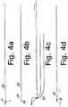
- Figures 4a through 4fare sequential views of the steps involved in forming one embodiment of the invention.
- Figure 5is a side elevational view of a cannulated driver used to insert a suture anchor at a surgical site.
- Figure 6is an exploded view of the distal tip of the driver of Figure 5, partially in cross-section.
- FIGS 7a through 7dshow the steps involved in producing an alternative embodiment of the invention.
- Figures 8a through 8cshow the steps involved in producing a third embodiment of the invention.
- Figure 9shows the manner in which the third embodiment of the invention may be loaded into a cannulated driver.
- Suture anchor 10comprises an anchor body 12 having a threaded distal portion 14, an apertured, proximal suture receiving portion 16 and an intermediate, hexagonally profiled drive portion 18.
- Suture receiving portion 16has an eyelet 20 with an axis transverse to axis 22 of anchor body 12, the eyelet having a diameter sufficient to accommodate a selected suture.
- eyelet 20 of suture anchor 10is threaded (by means not shown) with a predetermined length of suture 30 which is long enough to be suitable for the procedure for which the suture anchor is intended.
- Suture 30is threaded through the eyelet and folded back upon itself to have both ends placed side by side and to produce two equal-length suture portions extending from eyelet 20. (It is noted that some anchors and situations may utilize only a single suture portion extending from the anchor.)
- An elongated suture threader 34is inserted axially into and through a length of shrinkable polymeric tubing 32 ( Figure 4b) and both ends of suture 30 are passed through the pliable loop 36 at the distal end of threader 34 ( Figure 4c).
- reusable suture anchor driver 50has a distal tip 52, an elongated body 54, a handle 56, a suture retaining O-ring 58 and is cannulated throughout by axial bore 60.
- the distal end of bore 60communicates with interior channel 62 in the hollow, hexagonal driver tip adapted to receive suture and drive portion 18 of the suture anchor.
- Driver 50is known and often used with a threaded suture anchor such as anchor 10. However, prior to this invention, such use required the user to laboriously thread suture through the anchor body and then through the bore 60 of the driver.
- the suture extending from the proximal end of bore 60was held in place by lying in one of three radially extending grooves 63 (between bore 60 and O-ring 58) and being wrapped circumferentially around the driver handle adjacent O-ring 58.
- the inventionfacilitates the assembly of the anchor with the driver.
- the proximal end of tubing 32must, after shrinking, be sufficiently small in diameter to enable it to pass through channel 62.
- the maximum dimension of suture retaining portion 16is .064 inches while the maximum dimension of the hexagonal drive portion 18 across the flats is .077 inches. It has been found that shrinkable tubing having an outside diameter of .072 inches before heating and an outside diameter of .065 inches after heating is suitable for use with such an anchor. While numerous types of heat skrinkable tubing may be used, the shrink tubing may be, for example, fluorinated ethylenepropylene having a minimum expanded ID of .060 and a maximum recovered ID of .049.
- a smaller, Mini-REVO suture anchorhaving a maximum eyelet dimension of .055 inches and a maximum hexagonal dimension across the flats of .0557 may also be used.
- a shrinkable tubehaving an outside dimension of .062 inches before heating and .054 inches after heating is suitable, this shrink tubing having a minimum expanded ID of .054 inches and a maximum recovered ID of .044 inches.
- Both REVO and Mini-REVO suture anchorsare usable with number 0 braided polyester suture (3.55 mm metric) having an outside diameter of .35 mm min/.399 mm max and, since the shrinkage of the tubing is effective over a wide range, the system is also usable with a number 1 or 2 braided polyester suture (4 mm, 5mm) having an outside diameter of .40 mm min/.499 mm max or .50 mm min/.599 mm max, respectively. Obviously, threading the larger sutures through the tubing prior to shrinking will be more difficult although the resilience of the tubing permits considerable variation in sizes.
- the embodiment of Figure 4is used by simply pushing the free end of the anchor/suture/tubing assembly into the distal tip of channel 62 until it emerges from the proximal end of the driver bore. The assembly may then be pulled the rest of the way until the anchor is seated in channel 62. Note that the tubing may, if necessary, be pulled off the anchor or drive portion 18 in order to properly seat the anchor. In any event, the tubing may be removed from the suture once it is threaded through the driver.
- the essence of this inventionis to provide a suture, attached to a suture anchor, with a suture stiffening or support structure to enable the suture to be fed through a cannulated suture anchor driver.
- the support structureminimizes the lateral flexibility of the suture and increases its column strength. While numerous variations may be feasible, two alternative embodiments of the invention are described below.
- a suture anchoris threaded with suture in the same manner as shown in Figure 4a above.
- the embodiment of Figure 7shows both ends of the suture being inserted only a short distance (approximately 1 to 2 inches) into the shrink tubing 70 as shown in Figure 7b. This may be done with a tool such as the aforementioned threader 34 or by using a simple conical flaring tool (not shown) to flare the end of the shrink tubing and thereby form a conical entryway into which the suture ends may be pushed.
- the concept of providing a stiffening structure to the sutureis presented in the form of an elongated rod 80.
- the proximal ends of the sutureare inserted a short distance (approximately 1 ⁇ 2 inch) into the distal end of an elongated rod 80 ( Figure 8b).
- the rodmay be hollow or solid and the suture may be swaged into the rod ( Figure 8c) or attached in some other way.
- Rod 80is not shrinkable although its outside diameter must be small enough to fit within the bore of a cannulated driver.
- the anchor/suture/rod assembly of Figure 8may be easily threaded through a cannulated driver by holding the driver vertically and allowing gravity to feed rod 80 through bore 60 of the driver. The rod may then be removed.
Landscapes
- Health & Medical Sciences (AREA)
- Life Sciences & Earth Sciences (AREA)
- Surgery (AREA)
- Heart & Thoracic Surgery (AREA)
- Engineering & Computer Science (AREA)
- Biomedical Technology (AREA)
- Nuclear Medicine, Radiotherapy & Molecular Imaging (AREA)
- Medical Informatics (AREA)
- Molecular Biology (AREA)
- Animal Behavior & Ethology (AREA)
- General Health & Medical Sciences (AREA)
- Public Health (AREA)
- Veterinary Medicine (AREA)
- Rheumatology (AREA)
- Surgical Instruments (AREA)
Abstract


Description
- The invention relates generally to suture anchors for attaching soft tissue to bone. More particularly, the invention relates to a method and apparatus for producing a pre-loaded suture anchor assembly to facilitate attachment of a threaded suture anchor to a suture anchor driver for attaching the suture anchor at a selected work site.
- In the course of certain surgical procedures, soft tissue is secured to a selected bone surface either directly, via some type of implant, or indirectly via an implant (i.e. an anchor) to which suture is attached, the suture then being tied to the soft tissue to hold it in place. Anchors may be used to attach soft tissue such as ligaments, tendons, muscles, etc. to a surface from which the soft tissue has become detached and may also be used to secure soft tissue to supplementary attachment sites for reinforce-ment. For example, in urological applications anchors may be used in bladder neck suspensions to attach a portion of the bladder to an adjacent bone surface. Such soft tissue attachment may be done during either open or closed surgical procedures, the latter being generally referred to as arthroscopic or endoscopic surgery. The terms "arthroscopic" and "endoscopic" may be used interchangeably herein and are intended to encompass arthroscopic, endoscopic, laparoscopic, hysteroscopic or any other similar surgical procedures performed with elongated instruments inserted through small openings in the body.
- The prior art includes numerous types of suture anchors adapted to be secured in the bone, sometimes directly in one step and sometimes in pre-drilled holes or tunnels. The term "suture anchor" is used broadly and will be understood to refer to devices having a similar structure even if material other than suture is connected to the device. These devices generally comprise an anchor body designed to be embedded in the bone at a selected work site and a length of suture or other elongated structure extending from the body. The suture provides a means to tie the soft tissue adjacent the bone into which the anchor body has been embedded. While suture is sometimes tied to a portion of the anchor body, often the suture is threaded (i.e. pre-loaded) through an eyelet or other aperture in the anchor body so the suture may slide within the eyelet to facilitate subsequent knot tying steps. Alternatively, the suture may be non-slidably attached to have one or two fixed-length ends extending from the anchor body. Some prior art suture anchors are elongated and have annular ribs or radially extending barbs and are required to be pushed or hammered directly into bone or into a pre-formed bone tunnel (exemplified by U.S. Patents 5,102,421 (Anspach, Jr.); 5,141,520 (Goble et al.); 5,100,417 (Cerier et al.); 5,224,946 (Hayhurst et al.) and 5,261,914 (Warren)). Other suture anchors are threaded in order to be screwed into bone as exemplified by U.S. Patents 5,156,616 (Meadows et al.) and 4,632,100 (Somers et al.) .
- Devices used to insert suture anchors into bone surfaces are known as drivers and provide an interface between the actual implant and the surgeon performing the procedure. While this interface is most important in endoscopic surgical procedures because of the limited accessibility of the surgical site, prior art endoscopic procedures generally utilize devices and methods designed for open surgical procedures. All known procedures used to insert suture anchors endoscopically rely on elongated extensions which pass through the portals or cannulas used in the procedures. Similar elongated extensions are also used in open procedures. With respect to non-threaded or non-turnable suture anchors, these extensions merely are required to transmit longitudinal forces from the proximal end to the distal end where the suture anchor is situated. With respect to turnable or threaded suture anchors, the inserting device must be elongated as well as strong enough to transmit sufficient torque from the proximal end to the distal tip to turn the anchor.
- Suture anchors are often shipped to the customers with the suture already joined to the anchor body and with the body in turn attached to the driver, i.e. pre-loaded. The driver must, therefore, accommodate suture while it is turning. For example, U.S. Patents 5,411,506 (Goble et al.) and 5,411,523 (Goble) disclose a prior art suture anchor/driver assembly showing an anchor body preattached to sutures and held at the distal end of a cannulated driver. During arthroscopic or endoscopic procedures an elongated anchor/driver assembly enables a surgeon to manipulate the anchor within a portion of the body accessible only through a portal or other opening in the body. The suture anchor is provided with some means by which it may be attached and held to the distal end of the elongated driver while the proximal end is driven by the user.
- It is also known to provide a user with an unthreaded suture anchor body which must then be threaded and attached to a driver. For example, U.S. Patent 5,423,860 (Lizardi et al.) shows a device which facilitates loading a suture anchor into a non-cannulated driver. This device is a protective carrier in the form of a sleeve body which almost completely surrounds a suture anchor body having an aperture through its tip. The suture attached to the suture anchor is not retained by the protective carrier. The purpose of the protective carrier is to facilitate holding of the anchor as it is manipulated in order to thread a suture onto the anchor prior to assembling the anchor to the driver.
- Suture anchor drivers may be either disposable or reusable. A significant factor in determining whether a particular driver is reusable is the ease with which a suture anchor may be threaded with suture and then threaded through or attached to the driver to produce a pre-loaded anchor/driver assembly. The small sizes of the eyelets or other apertures make threading suture a time consuming process at best, especially in an operating room setting. Additionally, such threading through either an eyelet of the anchor or through the axial bore of a driver requires the use of elongated needle threaders and thereby adds to the complexity of equipment required for given surgical procedures. The afore-mentioned Lizardi et al. patent shows one type of reusable driver system utilizing a non-cannulated driver. The drivers in the aforementioned Goble patents are, however, cannulated and, therefore, not amenable to being easily loaded by a user.
- Prior art suture anchors are supplied to the customers pre-loaded as suture anchor/driver assemblies which utilize disposable cannulated drivers primarily because it is very difficult for a user to reuse the driver by attaching a suture to a new anchor body and then attaching the threaded anchor body to the driver. Attachment to a cannulated driver requires threading a flexible suture through a long, axial bore of the driver.
- It is accordingly an object of this invention to provide a method and device for facilitating the attachment of a suture anchor to a driver.
- It is also an object of this invention to provide a method and device for utilizing a pre-loaded suture anchor which may be easily assembled with a cannulated driver without use of other tools.
- It is an additional object of this invention to provide a method and device for enabling a user (such as a surgeon or other health care worker) to easily load (i.e. thread) a pre-loaded suture anchor into a reusable cannulated driver.
- These and other objects of the invention are achieved by the pre-loaded suture anchor assembly described herein. The essence of the invention is to provide a suture, attached to a suture anchor, with a suture stiffening or support structure to enable the suture to be fed through a cannulated suture anchor driver. The sutute anchor assembly may comprise: an anchor body having a suture receiving means for receiving suture; a suture having predetermined length and having a first end and a second end, said suture received in said suture receiving means and extending therefrom; a suture retaining means secured to said first and second ends of said suture for holding said ends of said suture. The suture retaining means may be a heat-shrinkable tube or an elongated rod swaged to the end of the suture.
- The invention also resides in a method of producing a pre-loaded suture anchor assembly for attachment to a suture anchor driver comprising the steps of: providing a suture anchor having a suture receiving means for receiving suture; providing a predetermined length of suture; engaging a predetermined length of suture with said suture receiving means so that at least one end of said suture extends from said suture anchor; providing a predetermined length of suture-supporting means for decreasing the lateral flexibility of an end portion of said suture to enable said suture to be engaged endwise with said driver; placing said at least one end of said suture into one end of said suture-supporting means; activating said suture-supporting means in order to cause it to frictionally engage said suture.
- Figure 1 is a side elevational view of a prior art suture anchor.
- Figure 2 is a left side view of Figure 1.
- Figure 3 is a top plan view of Figure 1.
- Figures 4a through 4f are sequential views of the steps involved in forming one embodiment of the invention.
- Figure 5 is a side elevational view of a cannulated driver used to insert a suture anchor at a surgical site.
- Figure 6 is an exploded view of the distal tip of the driver of Figure 5, partially in cross-section.
- Figures 7a through 7d show the steps involved in producing an alternative embodiment of the invention.
- Figures 8a through 8c show the steps involved in producing a third embodiment of the invention.
- Figure 9 shows the manner in which the third embodiment of the invention may be loaded into a cannulated driver.
- The method and apparatus of the present invention are best understood by reference to the Figures. While the invention is suitable for use with a variety of suture anchors, the preferred embodiment of the invention disclosed herein is explained in the context of a prior art threaded
suture anchor 10 shown in Figures 1 through 3 and sold under the trademark REVO by Linvatec Corporation, 11311 Concept Boulevard, Largo, Florida 34643.Suture anchor 10 comprises ananchor body 12 having a threadeddistal portion 14, an apertured, proximalsuture receiving portion 16 and an intermediate, hexagonally profileddrive portion 18. Suture receivingportion 16 has aneyelet 20 with an axis transverse to axis 22 ofanchor body 12, the eyelet having a diameter sufficient to accommodate a selected suture. - As shown in Figure 4a,
eyelet 20 ofsuture anchor 10 is threaded (by means not shown) with a predetermined length ofsuture 30 which is long enough to be suitable for the procedure for which the suture anchor is intended.Suture 30 is threaded through the eyelet and folded back upon itself to have both ends placed side by side and to produce two equal-length suture portions extending fromeyelet 20. (It is noted that some anchors and situations may utilize only a single suture portion extending from the anchor.) Anelongated suture threader 34 is inserted axially into and through a length of shrinkable polymeric tubing 32 (Figure 4b) and both ends ofsuture 30 are passed through thepliable loop 36 at the distal end of threader 34 (Figure 4c). Pullingthreader 34 out oftubing 32 causes suture 30 to extend axially through tubing 32 (Figure 4d), thedistal end 33 of the tubing is then, in this embodiment, positioned oversuture retaining portion 16 and/or the hexagonal drive portion 18 (Figure 4e). Other methods of threading the suture through the tubing may also be utilized. As will be explained further below, it should be noted thatsuture 30 need not extend entirely throughtubing 32 and that the tubing may extend beyond the suture.Tubing 32 must be a material which has an initial large internal diameter to easily receive the suture. Applying heat or some other stimulus to tubing 32 (by means not shown) causes it to shrink aroundsuture 30 to a smaller diameter and frictionally engage both the suture and the eyelet portion as shown in Figure 4f, or just the suture alone. - As shown in Figures 5 and 6, reusable
suture anchor driver 50 has adistal tip 52, anelongated body 54, ahandle 56, a suture retaining O-ring 58 and is cannulated throughout byaxial bore 60. The distal end ofbore 60 communicates withinterior channel 62 in the hollow, hexagonal driver tip adapted to receive suture and driveportion 18 of the suture anchor.Driver 50 is known and often used with a threaded suture anchor such asanchor 10. However, prior to this invention, such use required the user to laboriously thread suture through the anchor body and then through thebore 60 of the driver. After this was done, the suture extending from the proximal end ofbore 60 was held in place by lying in one of three radially extending grooves 63 (betweenbore 60 and O-ring 58) and being wrapped circumferentially around the driver handle adjacent O-ring 58. As will be understood below, the invention facilitates the assembly of the anchor with the driver. The proximal end oftubing 32 must, after shrinking, be sufficiently small in diameter to enable it to pass throughchannel 62. - In one preferred embodiment of this invention the maximum dimension of
suture retaining portion 16 is .064 inches while the maximum dimension of thehexagonal drive portion 18 across the flats is .077 inches. It has been found that shrinkable tubing having an outside diameter of .072 inches before heating and an outside diameter of .065 inches after heating is suitable for use with such an anchor. While numerous types of heat skrinkable tubing may be used, the shrink tubing may be, for example, fluorinated ethylenepropylene having a minimum expanded ID of .060 and a maximum recovered ID of .049. With respect to a second example, a smaller, Mini-REVO suture anchor having a maximum eyelet dimension of .055 inches and a maximum hexagonal dimension across the flats of .0557 may also be used. For this embodiment a shrinkable tube having an outside dimension of .062 inches before heating and .054 inches after heating is suitable, this shrink tubing having a minimum expanded ID of .054 inches and a maximum recovered ID of .044 inches. Both REVO and Mini-REVO suture anchors are usable with number 0 braided polyester suture (3.55 mm metric) having an outside diameter of .35 mm min/.399 mm max and, since the shrinkage of the tubing is effective over a wide range, the system is also usable with anumber 1 or 2 braided polyester suture (4 mm, 5mm) having an outside diameter of .40 mm min/.499 mm max or .50 mm min/.599 mm max, respectively. Obviously, threading the larger sutures through the tubing prior to shrinking will be more difficult although the resilience of the tubing permits considerable variation in sizes. - The embodiment of Figure 4 is used by simply pushing the free end of the anchor/suture/tubing assembly into the distal tip of
channel 62 until it emerges from the proximal end of the driver bore. The assembly may then be pulled the rest of the way until the anchor is seated inchannel 62. Note that the tubing may, if necessary, be pulled off the anchor or driveportion 18 in order to properly seat the anchor. In any event, the tubing may be removed from the suture once it is threaded through the driver. - The essence of this invention is to provide a suture, attached to a suture anchor, with a suture stiffening or support structure to enable the suture to be fed through a cannulated suture anchor driver. The support structure minimizes the lateral flexibility of the suture and increases its column strength. While numerous variations may be feasible, two alternative embodiments of the invention are described below.
- In Figure 7a, a suture anchor is threaded with suture in the same manner as shown in Figure 4a above. However, rather than inserting the entire length of suture into shrink tubing, the embodiment of Figure 7 shows both ends of the suture being inserted only a short distance (approximately 1 to 2 inches) into the
shrink tubing 70 as shown in Figure 7b. This may be done with a tool such as theaforementioned threader 34 or by using a simple conical flaring tool (not shown) to flare the end of the shrink tubing and thereby form a conical entryway into which the suture ends may be pushed. Heat is then applied to shrink the tubing to produce the anchor/suture/tubing assembly shown in Figure 7c in which the majority of the shrink tubing does not frictionally engage any suture. However, because of the stiffness of the shrink tubing itself the entire assembly may be easily pushed or threaded through a cannulated driver as shown in Figure 7d. The tubing may then be removed. - In the embodiment of Figure 8, the concept of providing a stiffening structure to the suture is presented in the form of an
elongated rod 80. After the suture is threaded through the anchor as shown in Figure 8a (a step identical to Figures 4a and 7a above), the proximal ends of the suture are inserted a short distance (approximately ½ inch) into the distal end of an elongated rod 80 (Figure 8b). The rod may be hollow or solid and the suture may be swaged into the rod (Figure 8c) or attached in some other way.Rod 80 is not shrinkable although its outside diameter must be small enough to fit within the bore of a cannulated driver. - As shown in Figure 9, the anchor/suture/rod assembly of Figure 8 may be easily threaded through a cannulated driver by holding the driver vertically and allowing gravity to feed
rod 80 throughbore 60 of the driver. The rod may then be removed. - It will be understood by those skilled in the art that numerous improvements and modifications may be made to the preferred embodiments of the invention disclosed herein without departing from the spirit and scope thereof.
Claims (16)
- A pre-loaded suture anchor assembly comprising:an anchor body (12) having a suture receiving means (16) for receiving suture (30);a suture (30) having predetermined length and having a first end and a second end, said suture (30) received in said suture receiving means (16) and extending therefrom;a suture retaining means (32,70,80) secured to said first and second ends of said suture (30) for holding said ends of said suture(30).
- A pre-loaded suture anchor assembly comprising:an anchor body (12) having a suture receiving means (16) for receiving suture;a suture (30) having predetermined length and having a first end and a second end said suture received in said suture receiving means (16) and extending therefrom;a hollow, elongated tubular sleeve means (32) having an axial bore with open distal and proximal ends for holding both of said ends of said suture (30) by frictionally engaging said ends within said axial bore of said sleeve means (32).
- A pre-loaded suture anchor assembly according to claim 2 wherein said distal end of said sleeve means (32) frictionally engages a predetermined portion of said anchor body.
- A pre-loaded suture anchor assembly according to claim 2 wherein said distal end of said sleeve means (32) comprises a heat-shrinkable tube (70).
- A pre-loaded suture anchor assembly according to claim 2 wherein said suture receiving means (16) comprises an eyelet member (20) and wherein said eyelet member (20) receives an intermediate portion of said suture (30) such that a pair of suture portions are formed from said suture, one suture portion extending between said anchor body (12) and said first suture ends and the other of said suture portions extending between said anchor body (12) and said second suture end.
- A pre-loaded suture anchor assembly according to claim 5 wherein said sleeve means (32) frictionally engages both said first and second ends of said suture (30).
- A pre-loaded suture anchor assembly according to claim 1 wherein said suture has two ends extending from said anchor and said suture retaining means comprises an elongated rod (80), having a proximal end and a distal end, said proximal end secured to the ends of said suture (30).
- A method of producing a pre-loaded suture anchor assembly for attachment to a suture anchor driver (50) comprising the steps of:providing a suture anchor having a suture receiving means (16) for receiving suture (30) ;providing a predetermined length of suture (30);engaging a predetermined length of suture with said suture receiving means (16) so that at least one end of said suture (30) extends from said suture anchor (10);providing a predetermined length of suture-supporting means (32,70,80) for decreasing the lateral flexibility of an end portion of said suture (30) to enable said suture (30) to be engaged endwise with said driver;placing said at least one end of said suture (30)into one end of said suture-supporting means (32,70,80);causing said suture-supporting means (32,70,80) to frictionally engage said suture (30).
- A method according to claim 8 wherein said suture receiving means (16) is an eyelet (20) and said step of engaging further comprises threading said at least one end of said suture (30) through said eyelet (20).
- A method according to claim 9 further comprising folding said suture (30) upon itself to cause both ends of said suture (30)to extend from said eyelet (20).
- A method according to claim 8 wherein said suture-supporting means is shrinkable tubing (70,32) and wherein the step of:
causing said suture-supporting means to frictionally engage said suture comprises shrinking said shrinkable tubing (32,70). - A method according to claim 8 wherein said suture-supporting means is an elongated rod (80) having a proximal end and a distal end.
- A method according to claim 8 further comprising the steps of:providing a cannulated anchor driver (50) having an axial bore (60) and an anchor engaging means at its distal end for engaging said anchor (10) in order to enable it to be driven at a predetermined work site;inserting said suture supporting means (32,70,80) into the axial bore (60)of said cannulated anchor driver (50);removing said suture supporting means (32,70,80) .
- A method according to claim 12 further comprising the steps of:providing a cannulated anchor driver (50)having an axial bore (60) and an anchor engaging means at its distal end for engaging said anchor (10) in order to enable it to be driven at a predetermined work site;holding said driver (50) in a vertical position to receive said elongated rod (80);inserting said rod (80) into said axial bore (60) and allowing it to fall by gravity through said driver (50).
- In combination, a suture anchor assembly comprising:a suture anchor (10), a predetermined length of suture (30) and a suture retaining means (32,70,80) for supporting at least one end of said suture(30); anda cannulated driver (50)for driving said suture anchor (10), said driver (50) having an axial bore (60) which has a predetermined diameter large enough to receive said suture retaining means (32,70,80) therethrough.
- A method of enabling a user to load a pre-loaded suture anchor assembly into a cannulated driver (50) for driving a suture anchor (10) comprising the steps of:providing a pre-loaded suture anchor assembly comprising a suture anchor (10), a predetermined length of suture (30) and suture support means (32,70,80) secured to at least one end of said suture (30) ;inserting said suture support means (32,70,80) into and through the bore (60)of said cannulated driver (50);removing said suture support means (32,70,80).
Applications Claiming Priority (2)
| Application Number | Priority Date | Filing Date | Title |
|---|---|---|---|
| US597792 | 1996-02-07 | ||
| US08/597,792US5697950A (en) | 1996-02-07 | 1996-02-07 | Pre-loaded suture anchor |
Publications (2)
| Publication Number | Publication Date |
|---|---|
| EP0788768A1true EP0788768A1 (en) | 1997-08-13 |
| EP0788768B1 EP0788768B1 (en) | 2004-11-24 |
Family
ID=24392943
Family Applications (1)
| Application Number | Title | Priority Date | Filing Date |
|---|---|---|---|
| EP97200347AExpired - LifetimeEP0788768B1 (en) | 1996-02-07 | 1997-02-06 | Pre-loaded suture anchor |
Country Status (3)
| Country | Link |
|---|---|
| US (1) | US5697950A (en) |
| EP (1) | EP0788768B1 (en) |
| DE (1) | DE69731676T2 (en) |
Cited By (1)
| Publication number | Priority date | Publication date | Assignee | Title |
|---|---|---|---|---|
| EP0824892B1 (en)* | 1996-08-22 | 2003-01-22 | Linvatec Corporation | Pre-loaded suture anchor with rigid extension |
Families Citing this family (139)
| Publication number | Priority date | Publication date | Assignee | Title |
|---|---|---|---|---|
| US6319270B1 (en) | 1996-08-05 | 2001-11-20 | Arthrex, Inc. | Headed bioabsorbable tissue anchor |
| US6117162A (en)* | 1996-08-05 | 2000-09-12 | Arthrex, Inc. | Corkscrew suture anchor |
| US6569188B2 (en) | 1996-08-05 | 2003-05-27 | Arthrex, Inc. | Hex drive bioabsorbable tissue anchor |
| US5718717A (en) | 1996-08-19 | 1998-02-17 | Bonutti; Peter M. | Suture anchor |
| US5948002A (en)* | 1996-11-15 | 1999-09-07 | Bonutti; Peter M. | Apparatus and method for use in positioning a suture anchor |
| US20050216059A1 (en)* | 2002-09-05 | 2005-09-29 | Bonutti Peter M | Method and apparatus for securing a suture |
| US6010525A (en)* | 1997-08-01 | 2000-01-04 | Peter M. Bonutti | Method and apparatus for securing a suture |
| US6045551A (en) | 1998-02-06 | 2000-04-04 | Bonutti; Peter M. | Bone suture |
| US6146406A (en) | 1998-02-12 | 2000-11-14 | Smith & Nephew, Inc. | Bone anchor |
| US6080184A (en)* | 1998-06-25 | 2000-06-27 | Linvatec Corporation | Package for retaining a suture and a suture anchor |
| US8343186B2 (en) | 2004-04-06 | 2013-01-01 | Arthrex, Inc. | Fully threaded suture anchor with transverse anchor pin |
| US9521999B2 (en) | 2005-09-13 | 2016-12-20 | Arthrex, Inc. | Fully-threaded bioabsorbable suture anchor |
| US20070225764A1 (en)* | 1999-02-02 | 2007-09-27 | Benavitz William C | Insert molded suture anchor |
| US7226469B2 (en)* | 1999-02-02 | 2007-06-05 | Arthrex, Inc. | Insert molded suture anchor |
| US6689153B1 (en) | 1999-04-16 | 2004-02-10 | Orthopaedic Biosystems Ltd, Inc. | Methods and apparatus for a coated anchoring device and/or suture |
| US6723107B1 (en) | 1999-04-19 | 2004-04-20 | Orthopaedic Biosystems Ltd. | Method and apparatus for suturing |
| US6447516B1 (en) | 1999-08-09 | 2002-09-10 | Peter M. Bonutti | Method of securing tissue |
| US6368343B1 (en) | 2000-03-13 | 2002-04-09 | Peter M. Bonutti | Method of using ultrasonic vibration to secure body tissue |
| US8128698B2 (en) | 1999-10-20 | 2012-03-06 | Anulex Technologies, Inc. | Method and apparatus for the treatment of the intervertebral disc annulus |
| US7052516B2 (en) | 1999-10-20 | 2006-05-30 | Anulex Technologies, Inc. | Spinal disc annulus reconstruction method and deformable spinal disc annulus stent |
| US7615076B2 (en) | 1999-10-20 | 2009-11-10 | Anulex Technologies, Inc. | Method and apparatus for the treatment of the intervertebral disc annulus |
| US6592625B2 (en) | 1999-10-20 | 2003-07-15 | Anulex Technologies, Inc. | Spinal disc annulus reconstruction method and spinal disc annulus stent |
| US7951201B2 (en) | 1999-10-20 | 2011-05-31 | Anulex Technologies, Inc. | Method and apparatus for the treatment of the intervertebral disc annulus |
| US7004970B2 (en) | 1999-10-20 | 2006-02-28 | Anulex Technologies, Inc. | Methods and devices for spinal disc annulus reconstruction and repair |
| US8632590B2 (en) | 1999-10-20 | 2014-01-21 | Anulex Technologies, Inc. | Apparatus and methods for the treatment of the intervertebral disc |
| US7935147B2 (en) | 1999-10-20 | 2011-05-03 | Anulex Technologies, Inc. | Method and apparatus for enhanced delivery of treatment device to the intervertebral disc annulus |
| US6524317B1 (en) | 1999-12-30 | 2003-02-25 | Opus Medical, Inc. | Method and apparatus for attaching connective tissues to bone using a knotless suture anchoring device |
| US6635073B2 (en)* | 2000-05-03 | 2003-10-21 | Peter M. Bonutti | Method of securing body tissue |
| US8932330B2 (en) | 2000-03-13 | 2015-01-13 | P Tech, Llc | Method and device for securing body tissue |
| US9138222B2 (en) | 2000-03-13 | 2015-09-22 | P Tech, Llc | Method and device for securing body tissue |
| US7094251B2 (en) | 2002-08-27 | 2006-08-22 | Marctec, Llc. | Apparatus and method for securing a suture |
| US6805695B2 (en) | 2000-04-04 | 2004-10-19 | Spinalabs, Llc | Devices and methods for annular repair of intervertebral discs |
| US7993369B2 (en) | 2000-06-22 | 2011-08-09 | Arthrex, Inc. | Graft fixation using a plug against suture |
| US6582453B1 (en)* | 2000-07-14 | 2003-06-24 | Opus Medical, Inc. | Method and apparatus for attaching connective tissues to bone using a suture anchoring device |
| US6660008B1 (en)* | 2001-06-07 | 2003-12-09 | Opus Medical, Inc. | Method and apparatus for attaching connective tissues to bone using a suture anchoring device |
| US6743233B1 (en) | 2000-08-02 | 2004-06-01 | Orthopaedic Biosystems, Ltd., Inc. | Medical screw and method of installation |
| US6585730B1 (en) | 2000-08-30 | 2003-07-01 | Opus Medical, Inc. | Method and apparatus for attaching connective tissues to bone using a knotless suture anchoring device |
| US6652561B1 (en) | 2000-10-13 | 2003-11-25 | Opus Medical, Inc | Method and apparatus for attaching connective tissues to bone using a perforated suture anchoring device |
| US6520980B1 (en) | 2000-11-02 | 2003-02-18 | Opus Medical, Inc. | Method and apparatus for attaching connective tissues to bone using a self-locking knotless suture anchoring device |
| US6770076B2 (en) | 2001-02-12 | 2004-08-03 | Opus Medical, Inc. | Method and apparatus for attaching connective tissues to bone using a knotless suture anchoring device |
| WO2006130693A2 (en) | 2005-06-01 | 2006-12-07 | Arthrocare Corporation | Knotless suture anchoring device having deforming section to accommodate sutures of various diameters |
| US6547800B2 (en) | 2001-06-06 | 2003-04-15 | Opus Medical, Inc. | Method and apparatus for attaching connective tissues to bone using a cortical bone anchoring device |
| US6719765B2 (en)* | 2001-12-03 | 2004-04-13 | Bonutti 2003 Trust-A | Magnetic suturing system and method |
| US6780198B1 (en) | 2001-12-06 | 2004-08-24 | Opus Medical, Inc. | Bone anchor insertion device |
| US6855157B2 (en) | 2002-02-04 | 2005-02-15 | Arthrocare Corporation | Method and apparatus for attaching connective tissues to bone using a knotless suture anchoring device |
| CA2477220C (en) | 2002-03-14 | 2007-11-06 | Jeffrey E. Yeung | Suture anchor and approximating device |
| US9155544B2 (en) | 2002-03-20 | 2015-10-13 | P Tech, Llc | Robotic systems and methods |
| US6984237B2 (en) | 2002-05-22 | 2006-01-10 | Orthopaedic Biosystems Ltd., Inc. | Suture passing surgical instrument |
| US6991636B2 (en)* | 2002-08-26 | 2006-01-31 | Arthrex, Inc. | Nitinol loop suture passer |
| US7497864B2 (en) | 2003-04-30 | 2009-03-03 | Marctec, Llc. | Tissue fastener and methods for using same |
| US7682374B2 (en) | 2003-10-21 | 2010-03-23 | Arthrocare Corporation | Knotless suture lock and bone anchor implant method |
| US20080039873A1 (en) | 2004-03-09 | 2008-02-14 | Marctec, Llc. | Method and device for securing body tissue |
| US8062334B2 (en) | 2004-06-02 | 2011-11-22 | Kfx Medical Corporation | Suture anchor |
| AU2005310320B2 (en) | 2004-06-02 | 2012-02-09 | Kfx Medical Corporation | System and method for attaching soft tissue to bone |
| US9271766B2 (en) | 2004-10-26 | 2016-03-01 | P Tech, Llc | Devices and methods for stabilizing tissue and implants |
| US9173647B2 (en) | 2004-10-26 | 2015-11-03 | P Tech, Llc | Tissue fixation system |
| US9463012B2 (en) | 2004-10-26 | 2016-10-11 | P Tech, Llc | Apparatus for guiding and positioning an implant |
| US20060089646A1 (en) | 2004-10-26 | 2006-04-27 | Bonutti Peter M | Devices and methods for stabilizing tissue and implants |
| US9089323B2 (en) | 2005-02-22 | 2015-07-28 | P Tech, Llc | Device and method for securing body tissue |
| US9364212B2 (en) | 2005-05-20 | 2016-06-14 | Neotract, Inc. | Suture anchoring devices and methods for use |
| US9149266B2 (en) | 2005-05-20 | 2015-10-06 | Neotract, Inc. | Deforming anchor device |
| US8945152B2 (en) | 2005-05-20 | 2015-02-03 | Neotract, Inc. | Multi-actuating trigger anchor delivery system |
| US9504461B2 (en) | 2005-05-20 | 2016-11-29 | Neotract, Inc. | Anchor delivery system |
| US10195014B2 (en) | 2005-05-20 | 2019-02-05 | Neotract, Inc. | Devices, systems and methods for treating benign prostatic hyperplasia and other conditions |
| US8394113B2 (en) | 2005-05-20 | 2013-03-12 | Neotract, Inc. | Coiled anchor device |
| US8603106B2 (en) | 2005-05-20 | 2013-12-10 | Neotract, Inc. | Integrated handle assembly for anchor delivery system |
| US9549739B2 (en) | 2005-05-20 | 2017-01-24 | Neotract, Inc. | Devices, systems and methods for treating benign prostatic hyperplasia and other conditions |
| US8668705B2 (en) | 2005-05-20 | 2014-03-11 | Neotract, Inc. | Latching anchor device |
| US10925587B2 (en) | 2005-05-20 | 2021-02-23 | Neotract, Inc. | Anchor delivery system |
| US8216254B2 (en) | 2005-05-20 | 2012-07-10 | Neotract, Inc. | Anchor delivery system with replaceable cartridge |
| US8834492B2 (en) | 2005-05-20 | 2014-09-16 | Neotract, Inc. | Continuous indentation lateral lobe apparatus and method |
| US7909836B2 (en) | 2005-05-20 | 2011-03-22 | Neotract, Inc. | Multi-actuating trigger anchor delivery system |
| US7758594B2 (en) | 2005-05-20 | 2010-07-20 | Neotract, Inc. | Devices, systems and methods for treating benign prostatic hyperplasia and other conditions |
| US8491606B2 (en) | 2005-05-20 | 2013-07-23 | Neotract, Inc. | Median lobe retraction apparatus and method |
| US8628542B2 (en) | 2005-05-20 | 2014-01-14 | Neotract, Inc. | Median lobe destruction apparatus and method |
| US8157815B2 (en) | 2005-05-20 | 2012-04-17 | Neotract, Inc. | Integrated handle assembly for anchor delivery system |
| US8333776B2 (en) | 2005-05-20 | 2012-12-18 | Neotract, Inc. | Anchor delivery system |
| US7645286B2 (en) | 2005-05-20 | 2010-01-12 | Neotract, Inc. | Devices, systems and methods for retracting, lifting, compressing, supporting or repositioning tissues or anatomical structures |
| US8425535B2 (en) | 2005-05-20 | 2013-04-23 | Neotract, Inc. | Multi-actuating trigger anchor delivery system |
| US8529584B2 (en) | 2005-05-20 | 2013-09-10 | Neotract, Inc. | Median lobe band implant apparatus and method |
| US7896891B2 (en) | 2005-05-20 | 2011-03-01 | Neotract, Inc. | Apparatus and method for manipulating or retracting tissue and anatomical structure |
| EP1762186B1 (en) | 2005-09-12 | 2011-02-16 | Arthrex, Inc. | Suture anchor with eyelet |
| US9439642B2 (en)* | 2006-02-07 | 2016-09-13 | P Tech, Llc | Methods and devices for utilizing bondable materials |
| US11278331B2 (en) | 2006-02-07 | 2022-03-22 | P Tech Llc | Method and devices for intracorporeal bonding of implants with thermal energy |
| US11253296B2 (en) | 2006-02-07 | 2022-02-22 | P Tech, Llc | Methods and devices for intracorporeal bonding of implants with thermal energy |
| US7967820B2 (en) | 2006-02-07 | 2011-06-28 | P Tech, Llc. | Methods and devices for trauma welding |
| US8496657B2 (en) | 2006-02-07 | 2013-07-30 | P Tech, Llc. | Methods for utilizing vibratory energy to weld, stake and/or remove implants |
| US7615061B2 (en) | 2006-02-28 | 2009-11-10 | Arthrocare Corporation | Bone anchor suture-loading system, method and apparatus |
| US11246638B2 (en) | 2006-05-03 | 2022-02-15 | P Tech, Llc | Methods and devices for utilizing bondable materials |
| US8133258B2 (en) | 2006-08-03 | 2012-03-13 | Arthrocare Corporation | Method and apparatus for attaching connective tissues to bone using a knotless suture anchoring device |
| US8951271B2 (en) | 2006-12-04 | 2015-02-10 | Implicitcare, Llc | Surgical threading device and method for using same |
| US9033999B2 (en) | 2006-12-04 | 2015-05-19 | Implicitcare, Llc | Surgical threading device with removable suture |
| US8025671B2 (en)* | 2006-12-04 | 2011-09-27 | Implicitcare, Llc | Surgical threading device and method for using same |
| US20080132917A1 (en)* | 2006-12-04 | 2008-06-05 | Gregory Paul Mueller | Surgical instrument docking device |
| US7566340B2 (en)* | 2006-12-04 | 2009-07-28 | Implicitcare, Llc | Surgical threading device and method for using same |
| US8617185B2 (en) | 2007-02-13 | 2013-12-31 | P Tech, Llc. | Fixation device |
| US8137381B2 (en) | 2007-04-25 | 2012-03-20 | Arthrocare Corporation | Knotless suture anchor having discrete polymer components and related methods |
| US8758366B2 (en)* | 2007-07-09 | 2014-06-24 | Neotract, Inc. | Multi-actuating trigger anchor delivery system |
| US8888795B2 (en)* | 2007-09-07 | 2014-11-18 | Boston Scientific Scimed, Inc. | Suture passer |
| US7963972B2 (en) | 2007-09-12 | 2011-06-21 | Arthrocare Corporation | Implant and delivery system for soft tissue repair |
| US8105343B2 (en) | 2008-06-30 | 2012-01-31 | Arthrocare Corporation | Independent suture tensioning and snaring apparatus |
| WO2010014825A1 (en) | 2008-07-30 | 2010-02-04 | Neotract, Inc. | Slotted anchor device |
| US9060766B2 (en)* | 2008-08-25 | 2015-06-23 | Daniel Larkin | Suture fixation kit of parts, system, and device |
| US8163022B2 (en) | 2008-10-14 | 2012-04-24 | Anulex Technologies, Inc. | Method and apparatus for the treatment of the intervertebral disc annulus |
| US8652153B2 (en) | 2010-01-11 | 2014-02-18 | Anulex Technologies, Inc. | Intervertebral disc annulus repair system and bone anchor delivery tool |
| US8814905B2 (en)* | 2010-11-23 | 2014-08-26 | Depuy Mitek, Llc | Surgical filament snare assemblies |
| US8556916B2 (en) | 2011-02-14 | 2013-10-15 | Smith & Nephew, Inc. | Method and device for suture manipulation |
| US9161749B2 (en) | 2011-04-14 | 2015-10-20 | Neotract, Inc. | Method and apparatus for treating sexual dysfunction |
| CA2840186A1 (en) | 2011-06-23 | 2012-12-27 | DePuy Synthes Products, LLC | Suture anchor system and method |
| US9636101B2 (en) | 2011-09-01 | 2017-05-02 | Arthrocare Corporation | Bone anchor having an integrated stress isolator |
| US10973513B2 (en) | 2011-09-29 | 2021-04-13 | Ethicon, Llc | Barbed suture having increased holding strength |
| US9023083B2 (en) | 2012-01-27 | 2015-05-05 | Arthrocare Corporation | Method for soft tissue repair with free floating suture locking member |
| US9198649B2 (en) | 2012-01-27 | 2015-12-01 | Arthrocare Corporation | Rotating locking member suture anchor and method for soft tissue repair |
| US9226742B2 (en) | 2012-01-27 | 2016-01-05 | Arthrocare Corporation | Restricted wedge suture anchor and method for soft tissue repair |
| US9034014B2 (en) | 2012-01-27 | 2015-05-19 | Arthrocare Corporation | Free floating wedge suture anchor for soft tissue repair |
| US9364210B2 (en) | 2012-01-27 | 2016-06-14 | Arthrocare Corporation | Biased wedge suture anchor and method for soft tissue repair |
| US9192375B2 (en) | 2012-02-29 | 2015-11-24 | Marker Medical, Llc | Surgical apparatus and method |
| US10292801B2 (en) | 2012-03-29 | 2019-05-21 | Neotract, Inc. | System for delivering anchors for treating incontinence |
| US9855028B2 (en) | 2012-04-06 | 2018-01-02 | Arthrocare Corporation | Multi-suture knotless anchor for attaching tissue to bone and related method |
| US9060763B2 (en) | 2012-05-07 | 2015-06-23 | Medos International Sàrl | Systems, devices, and methods for securing tissue |
| US10130353B2 (en) | 2012-06-29 | 2018-11-20 | Neotract, Inc. | Flexible system for delivering an anchor |
| US11672529B2 (en)* | 2012-09-17 | 2023-06-13 | Cilag Gmbh International | Barbed sutures having contoured barbs that facilitate passage through tissue and increase holding strength |
| US9763655B2 (en) | 2012-09-20 | 2017-09-19 | Medos International Sarl | Systems, devices, and methods for securing tissue using hard anchors |
| US10076377B2 (en) | 2013-01-05 | 2018-09-18 | P Tech, Llc | Fixation systems and methods |
| US10179012B2 (en) | 2013-01-28 | 2019-01-15 | Cartiva, Inc. | Systems and methods for orthopedic repair |
| US9737294B2 (en) | 2013-01-28 | 2017-08-22 | Cartiva, Inc. | Method and system for orthopedic repair |
| US9737293B2 (en) | 2013-03-15 | 2017-08-22 | Medos International Sàrl | Surgical constructs with collapsing suture loop and methods for securing tissue |
| US9936940B2 (en) | 2013-06-07 | 2018-04-10 | Biomet Sports Medicine, Llc | Method and apparatus for coupling soft tissue to bone |
| US9566056B2 (en) | 2013-11-05 | 2017-02-14 | Aevumed, Inc. | Apparatus and method for securing tissue to bone using suture anchors with a pre-loaded piercing structure and sutures |
| CN106456155A (en) | 2014-04-24 | 2017-02-22 | 史密夫和内修有限公司 | Suture passer |
| US9936943B1 (en) | 2014-08-07 | 2018-04-10 | Nicholas MANCINI | Suture passing surgical device with atraumatic grasper preventing accidental perforations |
| WO2016044053A1 (en) | 2014-09-19 | 2016-03-24 | Crossroads Extremity Systems, Llc | Bone fixation implant and means of fixation |
| US9795378B2 (en) | 2014-10-31 | 2017-10-24 | Ethicon, Inc. | Method for approximating wounds |
| US9451982B1 (en) | 2015-06-06 | 2016-09-27 | Coloplast A/S | System for implanting a penile prosthetic into a penis includes a delivery cap coupled to a tow suture |
| US10058393B2 (en) | 2015-10-21 | 2018-08-28 | P Tech, Llc | Systems and methods for navigation and visualization |
| WO2018081374A1 (en) | 2016-10-31 | 2018-05-03 | Smith & Nephew, Inc. | Suture passer and grasper instrument and method |
| ES2953556T3 (en) | 2017-12-23 | 2023-11-14 | Teleflex Life Sciences Ltd | Expandable Tissue Docking Apparatus |
| CN114286646B (en) | 2020-08-03 | 2024-03-08 | 泰利福生命科学有限公司 | Handle and cassette system for medical intervention |
| US20240090888A1 (en)* | 2022-09-15 | 2024-03-21 | Arthrex, Inc. | Surgical Constructs and Methods of Tissue Repairs |
Citations (13)
| Publication number | Priority date | Publication date | Assignee | Title |
|---|---|---|---|---|
| US4632100A (en) | 1985-08-29 | 1986-12-30 | Marlowe E. Goble | Suture anchor assembly |
| US4741330A (en)* | 1983-05-19 | 1988-05-03 | Hayhurst John O | Method and apparatus for anchoring and manipulating cartilage |
| US5100417A (en) | 1990-07-13 | 1992-03-31 | American Cyanamid Company | Suture anchor and driver assembly |
| US5102421A (en) | 1990-06-14 | 1992-04-07 | Wm. E. Anpach, III | Suture anchor and method of forming |
| EP0478949A1 (en)* | 1990-09-06 | 1992-04-08 | United States Surgical Corporation | Implant assist apparatus |
| US5141520A (en) | 1991-10-29 | 1992-08-25 | Marlowe Goble E | Harpoon suture anchor |
| US5156616A (en) | 1992-02-10 | 1992-10-20 | Meadows Bruce F | Apparatus and method for suture attachment |
| US5224946A (en) | 1990-07-02 | 1993-07-06 | American Cyanamid Company | Bone anchor and method of anchoring a suture to a bone |
| US5261914A (en) | 1987-09-02 | 1993-11-16 | Russell Warren | Surgical fastener |
| US5354298A (en)* | 1991-03-22 | 1994-10-11 | United States Surgical Corporation | Suture anchor installation system |
| US5411523A (en) | 1994-04-11 | 1995-05-02 | Mitek Surgical Products, Inc. | Suture anchor and driver combination |
| US5411506A (en) | 1994-04-11 | 1995-05-02 | Mitek Surgical Products, Inc. | Anchor driver |
| US5423860A (en) | 1993-05-28 | 1995-06-13 | American Cyanamid Company | Protective carrier for suture anchor |
Family Cites Families (19)
| Publication number | Priority date | Publication date | Assignee | Title |
|---|---|---|---|---|
| US4244370A (en)* | 1978-11-20 | 1981-01-13 | American Medical Systems, Inc. | Tool for positioning implantable medical prosthetic device _and method of using same |
| US4409974A (en)* | 1981-06-29 | 1983-10-18 | Freedland Jeffrey A | Bone-fixating surgical implant device |
| US4738255A (en)* | 1986-04-07 | 1988-04-19 | Biotron Labs, Inc. | Suture anchor system |
| US4898156A (en)* | 1987-05-18 | 1990-02-06 | Mitek Surgical Products, Inc. | Suture anchor |
| US4968315A (en)* | 1987-12-15 | 1990-11-06 | Mitek Surgical Products, Inc. | Suture anchor and suture anchor installation tool |
| US5084063A (en)* | 1989-09-27 | 1992-01-28 | United States Surgical Corporation | Surgical needle-suture attachment |
| US5034012A (en)* | 1989-11-21 | 1991-07-23 | Synthes (U.S.A.) | Intramedullary nail with loop tip |
| US5139520A (en)* | 1990-01-31 | 1992-08-18 | American Cyanamid Company | Method for acl reconstruction |
| US4989764A (en)* | 1990-03-26 | 1991-02-05 | Janice Hoffman | Disposable sewing implement |
| US4976712A (en)* | 1990-03-30 | 1990-12-11 | Vanderslik Julius | Retaining sleeve for surgical pin |
| US5041129A (en)* | 1990-07-02 | 1991-08-20 | Acufex Microsurgical, Inc. | Slotted suture anchor and method of anchoring a suture |
| US5037422A (en)* | 1990-07-02 | 1991-08-06 | Acufex Microsurgical, Inc. | Bone anchor and method of anchoring a suture to a bone |
| US5258016A (en)* | 1990-07-13 | 1993-11-02 | American Cyanamid Company | Suture anchor and driver assembly |
| US5368595A (en)* | 1990-09-06 | 1994-11-29 | United States Surgical Corporation | Implant assist apparatus |
| ATE174777T1 (en)* | 1990-09-25 | 1999-01-15 | Innovasive Devices Inc | BONE FIXATION DEVICE |
| US5176682A (en)* | 1992-06-01 | 1993-01-05 | Chow James C Y | Surgical implement |
| US5578057A (en)* | 1993-07-28 | 1996-11-26 | Mitek Surgical Products, Inc. | Anchoring device installation tool assembly and method |
| US5534011A (en)* | 1994-10-27 | 1996-07-09 | Vesica Medical, Inc. | Method and apparatus for threading a suture anchor |
| US5584860A (en)* | 1995-02-15 | 1996-12-17 | Mitek Surgical Products, Inc. | Suture anchor loader and driver |
- 1996
- 1996-02-07USUS08/597,792patent/US5697950A/ennot_activeExpired - Lifetime
- 1997
- 1997-02-06DEDE69731676Tpatent/DE69731676T2/ennot_activeExpired - Lifetime
- 1997-02-06EPEP97200347Apatent/EP0788768B1/ennot_activeExpired - Lifetime
Patent Citations (13)
| Publication number | Priority date | Publication date | Assignee | Title |
|---|---|---|---|---|
| US4741330A (en)* | 1983-05-19 | 1988-05-03 | Hayhurst John O | Method and apparatus for anchoring and manipulating cartilage |
| US4632100A (en) | 1985-08-29 | 1986-12-30 | Marlowe E. Goble | Suture anchor assembly |
| US5261914A (en) | 1987-09-02 | 1993-11-16 | Russell Warren | Surgical fastener |
| US5102421A (en) | 1990-06-14 | 1992-04-07 | Wm. E. Anpach, III | Suture anchor and method of forming |
| US5224946A (en) | 1990-07-02 | 1993-07-06 | American Cyanamid Company | Bone anchor and method of anchoring a suture to a bone |
| US5100417A (en) | 1990-07-13 | 1992-03-31 | American Cyanamid Company | Suture anchor and driver assembly |
| EP0478949A1 (en)* | 1990-09-06 | 1992-04-08 | United States Surgical Corporation | Implant assist apparatus |
| US5354298A (en)* | 1991-03-22 | 1994-10-11 | United States Surgical Corporation | Suture anchor installation system |
| US5141520A (en) | 1991-10-29 | 1992-08-25 | Marlowe Goble E | Harpoon suture anchor |
| US5156616A (en) | 1992-02-10 | 1992-10-20 | Meadows Bruce F | Apparatus and method for suture attachment |
| US5423860A (en) | 1993-05-28 | 1995-06-13 | American Cyanamid Company | Protective carrier for suture anchor |
| US5411523A (en) | 1994-04-11 | 1995-05-02 | Mitek Surgical Products, Inc. | Suture anchor and driver combination |
| US5411506A (en) | 1994-04-11 | 1995-05-02 | Mitek Surgical Products, Inc. | Anchor driver |
Cited By (1)
| Publication number | Priority date | Publication date | Assignee | Title |
|---|---|---|---|---|
| EP0824892B1 (en)* | 1996-08-22 | 2003-01-22 | Linvatec Corporation | Pre-loaded suture anchor with rigid extension |
Also Published As
| Publication number | Publication date |
|---|---|
| DE69731676D1 (en) | 2004-12-30 |
| EP0788768B1 (en) | 2004-11-24 |
| DE69731676T2 (en) | 2005-04-07 |
| US5697950A (en) | 1997-12-16 |
Similar Documents
| Publication | Publication Date | Title |
|---|---|---|
| EP0788768B1 (en) | Pre-loaded suture anchor | |
| US5707394A (en) | Pre-loaded suture anchor with rigid extension | |
| US8114129B2 (en) | Apparatus and methods for tendon or ligament repair | |
| US5827291A (en) | Suture anchor driver with suture retainer | |
| US5871504A (en) | Anchor assembly and method for securing ligaments to bone | |
| AU2002227105B9 (en) | Knotless suture anchor and method for knotlessly securing tissues | |
| US5383905A (en) | Suture loop locking device | |
| US5441502A (en) | System and method for re-attaching soft tissue to bone | |
| US5591207A (en) | Driving system for inserting threaded suture anchors | |
| US6143029A (en) | Tendon guide device | |
| US6860887B1 (en) | Suture management method and system | |
| US20040267317A1 (en) | Methods for attaching tissue to bone | |
| US20040024420A1 (en) | Apparatus and methods for securing tendons or ligaments to bone | |
| US20070173845A1 (en) | Self-locking suture anchor, system and method | |
| JP2008501428A (en) | System and method for attaching soft tissue to bone | |
| AU2002227105A1 (en) | Knotless suture anchor and method for knotlessly securing tissues | |
| JP2005000660A (en) | Suturing thread fixing device accompanied by improved driving head | |
| EP0814708A1 (en) | Soft tissue anchor and method | |
| AU2002362989A1 (en) | Apparatus and methods for tendon or ligament repair |
Legal Events
| Date | Code | Title | Description |
|---|---|---|---|
| PUAI | Public reference made under article 153(3) epc to a published international application that has entered the european phase | Free format text:ORIGINAL CODE: 0009012 | |
| AK | Designated contracting states | Kind code of ref document:A1 Designated state(s):CH DE FR GB IT LI NL | |
| 17P | Request for examination filed | Effective date:19980213 | |
| RAP1 | Party data changed (applicant data changed or rights of an application transferred) | Owner name:LINVATEC CORPORATION | |
| 17Q | First examination report despatched | Effective date:20020306 | |
| GRAP | Despatch of communication of intention to grant a patent | Free format text:ORIGINAL CODE: EPIDOSNIGR1 | |
| GRAS | Grant fee paid | Free format text:ORIGINAL CODE: EPIDOSNIGR3 | |
| GRAA | (expected) grant | Free format text:ORIGINAL CODE: 0009210 | |
| AK | Designated contracting states | Kind code of ref document:B1 Designated state(s):CH DE FR GB IT LI NL | |
| PG25 | Lapsed in a contracting state [announced via postgrant information from national office to epo] | Ref country code:NL Free format text:LAPSE BECAUSE OF FAILURE TO SUBMIT A TRANSLATION OF THE DESCRIPTION OR TO PAY THE FEE WITHIN THE PRESCRIBED TIME-LIMIT Effective date:20041124 Ref country code:LI Free format text:LAPSE BECAUSE OF FAILURE TO SUBMIT A TRANSLATION OF THE DESCRIPTION OR TO PAY THE FEE WITHIN THE PRESCRIBED TIME-LIMIT Effective date:20041124 Ref country code:CH Free format text:LAPSE BECAUSE OF FAILURE TO SUBMIT A TRANSLATION OF THE DESCRIPTION OR TO PAY THE FEE WITHIN THE PRESCRIBED TIME-LIMIT Effective date:20041124 | |
| REG | Reference to a national code | Ref country code:GB Ref legal event code:FG4D | |
| REG | Reference to a national code | Ref country code:CH Ref legal event code:EP | |
| REF | Corresponds to: | Ref document number:69731676 Country of ref document:DE Date of ref document:20041230 Kind code of ref document:P | |
| NLV1 | Nl: lapsed or annulled due to failure to fulfill the requirements of art. 29p and 29m of the patents act | ||
| REG | Reference to a national code | Ref country code:CH Ref legal event code:PL | |
| ET | Fr: translation filed | ||
| PLBE | No opposition filed within time limit | Free format text:ORIGINAL CODE: 0009261 | |
| STAA | Information on the status of an ep patent application or granted ep patent | Free format text:STATUS: NO OPPOSITION FILED WITHIN TIME LIMIT | |
| 26N | No opposition filed | Effective date:20050825 | |
| PGFP | Annual fee paid to national office [announced via postgrant information from national office to epo] | Ref country code:IT Payment date:20060228 Year of fee payment:10 | |
| PG25 | Lapsed in a contracting state [announced via postgrant information from national office to epo] | Ref country code:IT Free format text:LAPSE BECAUSE OF NON-PAYMENT OF DUE FEES Effective date:20070206 | |
| REG | Reference to a national code | Ref country code:FR Ref legal event code:PLFP Year of fee payment:20 | |
| PGFP | Annual fee paid to national office [announced via postgrant information from national office to epo] | Ref country code:DE Payment date:20160226 Year of fee payment:20 | |
| PGFP | Annual fee paid to national office [announced via postgrant information from national office to epo] | Ref country code:FR Payment date:20160217 Year of fee payment:20 Ref country code:GB Payment date:20160226 Year of fee payment:20 | |
| REG | Reference to a national code | Ref country code:DE Ref legal event code:R071 Ref document number:69731676 Country of ref document:DE | |
| REG | Reference to a national code | Ref country code:GB Ref legal event code:PE20 Expiry date:20170205 | |
| PG25 | Lapsed in a contracting state [announced via postgrant information from national office to epo] | Ref country code:GB Free format text:LAPSE BECAUSE OF EXPIRATION OF PROTECTION Effective date:20170205 |