EP0787977A2 - Method for precise determination of the velocity of a liquid, in particular of aortic flow, using an intracorporal probe - Google Patents
Method for precise determination of the velocity of a liquid, in particular of aortic flow, using an intracorporal probeDownload PDFInfo
- Publication number
- EP0787977A2 EP0787977A2EP97104304AEP97104304AEP0787977A2EP 0787977 A2EP0787977 A2EP 0787977A2EP 97104304 AEP97104304 AEP 97104304AEP 97104304 AEP97104304 AEP 97104304AEP 0787977 A2EP0787977 A2EP 0787977A2
- Authority
- EP
- European Patent Office
- Prior art keywords
- energy
- speed
- probe
- total
- aorta
- Prior art date
- Legal status (The legal status is an assumption and is not a legal conclusion. Google has not performed a legal analysis and makes no representation as to the accuracy of the status listed.)
- Granted
Links
- 239000000523sampleSubstances0.000titleclaimsabstractdescription62
- 238000000034methodMethods0.000titleclaimsdescription33
- 239000007788liquidSubstances0.000titledescription4
- 238000012937correctionMethods0.000claimsabstractdescription35
- 239000002245particleSubstances0.000claimsabstractdescription30
- 210000004369bloodAnatomy0.000claimsabstractdescription14
- 239000008280bloodSubstances0.000claimsabstractdescription14
- 210000000709aortaAnatomy0.000claimsdescription47
- 238000005259measurementMethods0.000claimsdescription37
- 210000003743erythrocyteAnatomy0.000claimsdescription18
- 238000012545processingMethods0.000claimsdescription13
- 239000012530fluidSubstances0.000claimsdescription12
- 230000000694effectsEffects0.000claimsdescription8
- 210000003238esophagusAnatomy0.000claimsdescription7
- 239000000725suspensionSubstances0.000claimsdescription7
- 210000004027cellAnatomy0.000claimsdescription5
- 230000004087circulationEffects0.000claimsdescription4
- 230000001419dependent effectEffects0.000claimsdescription3
- 230000001360synchronised effectEffects0.000claimsdescription2
- 238000002604ultrasonographyMethods0.000abstract2
- 238000002592echocardiographyMethods0.000description6
- 230000017531blood circulationEffects0.000description4
- 230000000747cardiac effectEffects0.000description3
- 238000010276constructionMethods0.000description3
- VYPSYNLAJGMNEJ-UHFFFAOYSA-Nsilicon dioxideInorganic materialsO=[Si]=OVYPSYNLAJGMNEJ-UHFFFAOYSA-N0.000description3
- 210000003462veinAnatomy0.000description3
- 239000000470constituentSubstances0.000description1
- 230000007423decreaseEffects0.000description1
- 238000001514detection methodMethods0.000description1
- 238000010586diagramMethods0.000description1
- 230000004907fluxEffects0.000description1
- 230000001788irregularEffects0.000description1
- 239000000463materialSubstances0.000description1
- 238000012986modificationMethods0.000description1
- 230000004048modificationEffects0.000description1
- 210000004400mucous membraneAnatomy0.000description1
- 231100000956nontoxicityToxicity0.000description1
- 239000010453quartzSubstances0.000description1
- 239000000377silicon dioxideSubstances0.000description1
Images

Classifications
- A—HUMAN NECESSITIES
- A61—MEDICAL OR VETERINARY SCIENCE; HYGIENE
- A61B—DIAGNOSIS; SURGERY; IDENTIFICATION
- A61B8/00—Diagnosis using ultrasonic, sonic or infrasonic waves
- A61B8/12—Diagnosis using ultrasonic, sonic or infrasonic waves in body cavities or body tracts, e.g. by using catheters
- A—HUMAN NECESSITIES
- A61—MEDICAL OR VETERINARY SCIENCE; HYGIENE
- A61B—DIAGNOSIS; SURGERY; IDENTIFICATION
- A61B8/00—Diagnosis using ultrasonic, sonic or infrasonic waves
- A61B8/06—Measuring blood flow
- A—HUMAN NECESSITIES
- A61—MEDICAL OR VETERINARY SCIENCE; HYGIENE
- A61B—DIAGNOSIS; SURGERY; IDENTIFICATION
- A61B8/00—Diagnosis using ultrasonic, sonic or infrasonic waves
- A61B8/44—Constructional features of the ultrasonic, sonic or infrasonic diagnostic device
- A61B8/4444—Constructional features of the ultrasonic, sonic or infrasonic diagnostic device related to the probe
- A61B8/445—Details of catheter construction
- G—PHYSICS
- G01—MEASURING; TESTING
- G01F—MEASURING VOLUME, VOLUME FLOW, MASS FLOW OR LIQUID LEVEL; METERING BY VOLUME
- G01F1/00—Measuring the volume flow or mass flow of fluid or fluent solid material wherein the fluid passes through a meter in a continuous flow
- G01F1/66—Measuring the volume flow or mass flow of fluid or fluent solid material wherein the fluid passes through a meter in a continuous flow by measuring frequency, phase shift or propagation time of electromagnetic or other waves, e.g. using ultrasonic flowmeters
- G01F1/662—Constructional details
- G—PHYSICS
- G01—MEASURING; TESTING
- G01F—MEASURING VOLUME, VOLUME FLOW, MASS FLOW OR LIQUID LEVEL; METERING BY VOLUME
- G01F1/00—Measuring the volume flow or mass flow of fluid or fluent solid material wherein the fluid passes through a meter in a continuous flow
- G01F1/66—Measuring the volume flow or mass flow of fluid or fluent solid material wherein the fluid passes through a meter in a continuous flow by measuring frequency, phase shift or propagation time of electromagnetic or other waves, e.g. using ultrasonic flowmeters
- G01F1/663—Measuring the volume flow or mass flow of fluid or fluent solid material wherein the fluid passes through a meter in a continuous flow by measuring frequency, phase shift or propagation time of electromagnetic or other waves, e.g. using ultrasonic flowmeters by measuring Doppler frequency shift
- G—PHYSICS
- G01—MEASURING; TESTING
- G01P—MEASURING LINEAR OR ANGULAR SPEED, ACCELERATION, DECELERATION, OR SHOCK; INDICATING PRESENCE, ABSENCE, OR DIRECTION, OF MOVEMENT
- G01P5/00—Measuring speed of fluids, e.g. of air stream; Measuring speed of bodies relative to fluids, e.g. of ship, of aircraft
- G01P5/24—Measuring speed of fluids, e.g. of air stream; Measuring speed of bodies relative to fluids, e.g. of ship, of aircraft by measuring the direct influence of the streaming fluid on the properties of a detecting acoustical wave
- G01P5/241—Measuring speed of fluids, e.g. of air stream; Measuring speed of bodies relative to fluids, e.g. of ship, of aircraft by measuring the direct influence of the streaming fluid on the properties of a detecting acoustical wave by using reflection of acoustical waves, i.e. Doppler-effect
Definitions
- the present inventionrelates to the technical field of ultrasonic probes, in the general sense, used for carrying out velocity and / or flow rate measurements and it relates in particular to the field of ultrasonic probes capable of ensuring intracorporeal measurements, by being introduced into the human body through a natural orifice.
- the inventionfinds a particularly advantageous application for measuring the aortic flow rate by means of the probe introduced inside the esophagus.
- Document FR-A-2 424 733proposed an intracorporeal probe composed of a catheter forming a flexible sheath containing a flexible connected, by one of its ends, to a support block on which is mounted at least one ultrasonic transducer connected, externally to the catheter, to a control and processing unit.
- the other end of the hoseis mounted integral with a member for rotating the support block on itself.
- Such a probemakes it possible, by the Doppler effect, to determine the speed and, consequently, if the diameter is otherwise known, the flow of blood circulating inside a vessel. It is recalled that the flow rate is equal to the section of the vessel multiplied by the average space speed inside the vessel.
- such a probeensures the measurement of the average speed which is carried out using an ultrasonic transducer whose beam does not cover the entire surface of the cross section of the vessel.
- incorrect positions of the probecan give rise to Doppler signals having all the appearances of the sought signal but leading to inaccurate values of the flow rate.
- the ultrasonic beamcan also partially cover an area outside the vessel, so that the measuring device takes into account mobile elements external to the vessel, which is a source of error.
- the spatial velocity profileshows zones of zero velocities or sufficiently low so that they cannot be measured using the probe and the treatment device used. jointly.
- the average spatial velocity thus measuredis erroneous, since only targets animated with a sufficiently rapid movement are taken into account. Under these conditions, the measurement of the flow rate leads to an extremely large error since the average speed measured is then multiplied by the total section of the vessel. This error is all the more important as the surface covered by the immobile liquid veins or sufficiently slow not to be detected by the probe is itself large compared to the section of the vessel.
- the present inventiontherefore aims to remedy the above drawbacks by proposing a method and a probe capable of significantly improving the accuracy of the measurement of the spatial speed of a moving target for an accurate measurement of the flow rate of the target and, in particular , aortic flow.
- Another object of the inventionis to propose a method and a probe capable of ensuring an accurate measurement of speed exclusively over the entire section of the moving target.
- Another object of the inventionis to propose a method and a probe capable of carrying out precise measurements of speed and, consequently, of flow, in a fluid comprising particles in suspension, circulating in a conduit, this circulation being able to be in particular of the pulsed type and thus present at certain times a zero speed or even a retrograde flow.
- Another object of the inventionis to provide a method and a probe capable of making precise measurements of speed and, consequently, of flow, of the blood in the aorta.
- the solutionmust make it possible to measure the speed and therefore the flow of blood in the aorta by the use of an endocavitary type probe introduced into the esophagus until it is positioned opposite the aorta, as well during diastole as systole, or flows presenting fluid veins of variable speed in particular due to an irregular or pulsed flow, which can include a zero speed or even a retrograde flow.
- the probecomprises at least one support block on which is mounted at least one ultrasonic transducer connected to a control and processing unit.
- the speed or the flow rateis corrected only when the measured energy is less than a given threshold (N) of between 10 and 50% and, preferably, of the order of 25%, of the maximum backscattered energy.
- the methodis characterized in that the total backscattered energy (E S ) is measured and averaged over several cycles during which all of the particles in motion occupy all or substantially the entire total section of the duct .
- thisis characterized in that the speed or flow measurement is corrected by a correction factor (K) depending on the ratio of the partial energy (E D ) to the energy total (E S ), the correction factor (K) being weighted by a correction coefficient depending on the characteristics of the wide beam transducer and the speed and / or energy measuring means.
- Kcorrection factor
- This processcan be advantageously characterized in that the aforementioned fluid circulates in a pulsed manner, and in particular has moments when the speed can cancel and even present a retrograde flow.
- a probe having a longitudinal axiscomprising a probe body and at least one support block provided with rotation means making it possible to rotate the block support around the longitudinal axis of the probe, independently of the body of the probe, said support block comprising at least one ultrasonic transducer with a narrow beam and at least one ultrasonic transducer with a wide beam, mounted in said probe to present its beam wide in a known relative position relative to that of the ultrasonic narrow beam transducer, the probe is introduced into a conduit separate from the conduit in which the fluid comprising the suspended particles circulates, and the rotation of the narrow beam transducer is varied around from the longitudinal axis of the probe to a position for which the amplitude of the reflected ultrasonic energy indicates the perpend icularity of the ultrasonic narrow beam vis-à-vis the wall of the conduit in which the fluid comprising the suspended particles circulates.
- this methodis characterized in that the total backscattered energy (E S ) is substantially synchronous with the systole.
- this methodis characterized in that the total cross-section of the aorta is measured using an ultrasonic transducer with a narrow beam disposed disposed outside the aorta and substantially perpendicular to the longitudinal axis of the aorta and meets this axis, and in that the instantaneous velocity is measured at a given instant using an ultrasonic beam transducer wide arranged with an inclination ( ⁇ ) relative to the ultrasonic transducer with narrow beam, by Doppler effect, and in that one selects only the speeds of the erythrocytes in movement located inside the aorta, not including the walls of the aorta.
- the speed or the flow rateis corrected only when the energy measured is less than a given threshold (N) of between 10 and 50% and, preferably, on the order of 25%, of the maximum backscattered energy.
- this methodis characterized in that the total backscattered energy (E S ) is measured and averaged over several cycles during which the red blood cells in motion occupy the entire section of the aorta.
- the speed or flow measurementis corrected by a correction factor (K) depending on the ratio of the localized energy (E D ) to the total energy (E S ), the correction factor (K) being weighted by a correction coefficient depending on the characteristics of the wide beam transducer and of the Doppler effect processing means in particular for determining the speed and / or the energy .
- the probeis of the endocavitary type and is introduced into the esophagus until it is positioned opposite the aorta, said probe having a longitudinal axis, comprising a probe body and at least one block -support provided with rotation means, said narrow beam transducer element as well as the wide beam ultrasonic transducer being mounted on the support block, and the rotation means are acted to rotate the narrow beam transducer around the the longitudinal axis of the probe, relative to the probe body, to a position for which the amplitude of the reflected ultrasonic energy indicates the perpendicularity of the ultrasonic narrow beam with respect to the wall of the aorta.
- the probemakes it possible to carry out measurements exclusively on the total section of a medium or of a given duct, such as the aorta.
- Figure 1is a sectional elevation of a currently preferred embodiment of the invention, shown schematically in the operating position in the esophagus facing the aorta.
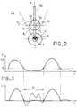
- Figure 2is a projection view of the cross section taken substantially along lines II-II of Figure 1 and showing a characteristic detail of the invention.
- FIG. 3is a diagram illustrating, over time, the energy backscattered by the moving target, namely here the blood circulating in the aorta.
- FIG. 4is an example of a curve of speed as a function of time, obtained from the probe according to the invention according to FIGS. 1 and 2 before correction (shown diagrammatically in broken lines) and after correction.
- FIG. 1shows an exemplary embodiment of a probe according to the invention, intended to ensure intracorporeal measurements of speed and / or of flow.
- the intracorporeal probecomprises a catheter 1 forming a sheath or a flexible tube produced in a known manner by materials chosen for their characteristics of non-toxicity and good tolerance for the mucous membranes.
- the sheath 1contains a hose 2 which is connected, by one of its ends, to at least one support block 3 on which ultrasonic transducers 4 and 5 are mounted.
- this end of the probe 1which is intended to be introduced into the body, is provided with a balloon 6 surrounding the support block 3.
- the transducers 4, 5are connected to an electrical cable 7 placed in the sheath 1 and exiting outside the catheter to be connected to a unit 8 for controlling the transducers and for processing the signals delivered by the latter.
- the end of the hose 2, opposite that provided with the support block 3,is connected to an operating member 9, such as a knurled button ensuring a rotation of the hose 2 on itself.
- the support block 3is arranged to receive at least one ultrasonic transducer 4, having a so-called wide beam 4a, namely adapted to cover at least the whole section S of a medium 10, such as 'a vessel forming, preferably, the aorta and occupied by a moving target 11 formed, for example, by a blood flow ( Figure 2).
- the transducer 4is placed on a support plane 12 formed in the support block 3.
- the transducer 4is inclined relative to the longitudinal axis xx ' common to hose 2 and support block 3, so as to allow detection of blood speed by Doppler effect.
- the transducer 4 usedis the nature P1 60 type transducer, of cylindrical sector shape with dimensions 4/4 mm, with a radius of curvature of 6 mm and marketed by the company Quartz and Silica.
- the support block 3is also equipped with an ultrasonic transducer 5 having a beam 5a considered narrow with respect to the section S of the aorta 10 and with respect to the beam 4a.
- the transducer 5, of the flat or localized beam typeis mounted on the support block 3, so that its beam 5a is preferably centered on the symmetrical plane P of the wide beam, passing through the axis x- x '.
- the narrow beam 5ais offset by an angle of divergence ⁇ with respect to the wide beam 4a and is preferably oriented in a direction substantially perpendicular to the axis x-x '.
- the transducer 5can be fixed on the support block 3, so that its beam 5a is in a different but known relative position with respect to that of the wide beam 4a.
- the transducers 4 and 5can be mounted on separate support blocks whose relative positions are known, in particular by construction.
- the probe described in the illustrated exampleis intended to be introduced through a natural orifice in a natural way, such as the esophagus 13 shown in phantom, then displaced axially so that the transducers 4 and 5 are placed opposite a section S of the aorta 10.
- the support block 3is then moved on itself by means of the operating button 9 transmitting its effect through the hose 2, so as to orient the transducers 4, 5 in azimuth properly .
- the narrow beam transducer 5is connected to the unit 8 which comprises means for measuring and processing the signal characteristics of the transducer to narrow beam 5.
- control and processing unit 8comprises means 14 connected to the transducer 5 by a link 7 1 and designed to determine the amplitude of the signals received echoed by the narrow beam transducer 5.
- the determination means 14are connected to means 15 designed to detect the maximums of the amplitude of the reflected signals. Conventionally, it is consider that the amplitude of the echoes of the transducer 5 is maximum when its beam 5a is perpendicular to the walls of the vessel 10.
- the support block 3is moved in azimuth via the button 9, until it occupies a position in which the amplitude of the echoes of the signal from transducer 5 appears maximum.
- the transducer 4is then, by construction, suitably oriented, so that its wide beam 4a insonifies the entire section S of the aorta 10. It is thus possible to give a single correct orientation to the probe, in the measure where the amplitude of the echoes of the walls decreases significantly for a small angular deviation. Furthermore, it should be noted that the ultrasonic transducer 4 makes it possible to measure the speed over the entire section of the vessel 9, insofar as this entire section is insonified by the wide beam 4a.
- the control and processing unit 8comprises means 16 designed to determine this interval P 2 -P 1 .
- the means 16are connected to the means 15, in order to determine the interval d 2 -d 1 corresponding to the two extreme points of the aorta detected from the maximums of the amplitude of the echoes relative to the signals from the transducer 5.
- the knowledge of the interval d 2 -d 1makes it possible to calculate the section since it is known or considered that the vessel is of circular section.
- the means 16determine the interval P 2 -P 1 from the interval d 2 -d 1 and the angle of divergence ⁇ between the two beams, known in particular by construction.
- These determination means 16control selection means 17 connected to the transducer 4 by a link 7 2 .
- These means 17make it possible to select only the echoes of the signals from the transducer 4 which are obtained in a response time range corresponding to the interval P 2 -P 1 .
- the selection means 17are connected to conventional processing means 19 ensuring the obtaining of a Doppler signal.
- These processing means 19are connected to means 20 known per se, capable of determining the mean spatial speed V m of the blood passing through the section S of the aorta 10.
- the combined use of at least one wide beam transducer 4 and at least one narrow beam transducer 5allows the measurement of the velocities over the entire section of the aorta 10 without taking account of elements located at the exterior of such a vessel.
- the velocity measurement fieldthus coincides as narrowly as possible with the section S of the aorta.
- the probeis capable of ensuring precise measurements of spatial average speed which take account of the section of the liquid veins animated by a speed zero or sufficiently low to be considered as zero by the means 19, 20 operating in a conventional manner.
- the probe according to the inventionis thus capable of ensuring velocity measurements which take account of the effective or actual section occupied by the red blood cells considered to be moving inside the aorta.
- the unit 8comprises means 21 capable of measuring the energy backscattered by the moving particles, namely the red cells in the case of blood.
- the backscattered energy Ewhich is proportional to the number of red blood cells in motion, is measured at each instant, in order to know the mass of liquid in motion ( Figure 3).
- the energy calculation means 21which receive the Doppler signal from the processing means 19, determine at each instant the amplitude or the energy E backscattered by the moving targets.
- the Doppler signal amplitudeis proportional to the square root of the backscattered energy.
- the output of the calculation means 21is connected to means 22 designed to allow the backscattered energy to pass at one or more defined instants, in particular during systole.
- the means 22are thus connected to means 23 capable of determining said defined instants and in particular the instant when the systole occurs.
- systolecan be detected from maximum blood speed, backscattered energy, or an electrocardiogram.
- the means 22therefore deliver the value of the backscattered energy E S during systole.
- the backscattered energy E Sis measured over several cardiac cycles, for example of the order of ten, then averaged, in order to take account of normal physiological variations.
- the correction factor Kis determined by correction means 24 connected to the means 21, 22.
- the correction means 24weight the factor K by a practical correction coefficient which takes account of the technical characteristics of the transducer 4 used and means 19, in particular of the minimum value of the detected speeds and of the bandwidth of the Doppler signal.
- These correction means 24are connected to means 25 which are connected to the means 20 for determining the spatial average speed.
- These means 25make it possible to calculate, on the basis of the values of the average spatial speed and of the correction factor K, the corrected average speed V C and, consequently, the flow of the moving blood on the localized surface S D , from knowledge of the section of the ship.
- FIG. 4illustrates an example of a curve giving the corrected speed V C as a function of time. This curve makes it possible to appreciate the correction carried out from the raw measurement speeds which are shown diagrammatically in broken lines during the diastole D.
- the method according to the inventionmakes it possible to obtain a high precision on the speed measurements and, consequently , of blood flow rates, since these measured values take account of the effective section participating in the blood flow rate.
- the correction factor determined by the means 24is applied only when the backscattered energy is less than a given threshold N, of fixed or adjustable nature, to take account of both the variations physiological and normal statistical variations of the Doppler signal known elsewhere.
- the threshold Nis between 10 and 50% of the maximum backscattered energy E S during systole and, preferably, of the order of 25%.
- the various constituent means of the unit 8can be produced in a programmed or wired manner.
- the various circuits necessary for the operation of the transducers 4, 5have not been described more precisely, since they are not part of the invention and are known per se.
- the above descriptionrelates to an intracorporeal or endocavitary probe.
- the object of the inventioncan be applied to an extracorporeal probe.
- the probedoes not include the catheter 1 and the hose 2.
- the section (S S)is defined by the section occupied by the particles suspended in the duct, for example the red blood cells in the aorta, when all or substantially all is considered to be in motion, in the plane of scanning the section of the wide beam transducer 4, said section (S S ) being substantially equal to the section (S) of the scanned duct, here the aorta, as shown in FIG. 2.
- the partial section (S D )is the section occupied at all times by the particles suspended in the duct, for example the red blood cells detected as being in motion and which can represent a very localized area as shown in FIG. 2.
- the corrected speed valuewas 15.36 cm / second.
Landscapes
- Health & Medical Sciences (AREA)
- Life Sciences & Earth Sciences (AREA)
- Physics & Mathematics (AREA)
- Engineering & Computer Science (AREA)
- General Health & Medical Sciences (AREA)
- Molecular Biology (AREA)
- Radiology & Medical Imaging (AREA)
- Nuclear Medicine, Radiotherapy & Molecular Imaging (AREA)
- Biomedical Technology (AREA)
- Heart & Thoracic Surgery (AREA)
- Medical Informatics (AREA)
- General Physics & Mathematics (AREA)
- Surgery (AREA)
- Animal Behavior & Ethology (AREA)
- Biophysics (AREA)
- Public Health (AREA)
- Veterinary Medicine (AREA)
- Pathology (AREA)
- Electromagnetism (AREA)
- Fluid Mechanics (AREA)
- Hematology (AREA)
- Acoustics & Sound (AREA)
- Multimedia (AREA)
- Aviation & Aerospace Engineering (AREA)
- Ultra Sonic Daignosis Equipment (AREA)
- Measuring Volume Flow (AREA)
- Indicating Or Recording The Presence, Absence, Or Direction Of Movement (AREA)
- Automatic Analysis And Handling Materials Therefor (AREA)
- Measuring Pulse, Heart Rate, Blood Pressure Or Blood Flow (AREA)
Abstract
Description
Translated fromFrenchLa présente invention concerne le domaine technique des sondes ultrasonores, au sens général, utilisées pour procéder à des mesures de vitesse et/ou de débit et elle vise en particulier le domaine des sondes ultrasonores aptes à assurer des mesures intracorporelles, en étant introduites dans le corps humain par un orifice naturel.The present invention relates to the technical field of ultrasonic probes, in the general sense, used for carrying out velocity and / or flow rate measurements and it relates in particular to the field of ultrasonic probes capable of ensuring intracorporeal measurements, by being introduced into the human body through a natural orifice.
L'invention trouve une application particulièrement avantageuse pour la mesure du débit aortique par l'intermédiaire de la sonde introduite à l'intérieur de l'oesophage.The invention finds a particularly advantageous application for measuring the aortic flow rate by means of the probe introduced inside the esophagus.
Le document FR-A-2 424 733 a proposé une sonde intracorporelle composée d'un cathéter formant une gaine souple contenant un flexible relié, par l'une de ses extrémités, à un bloc-support sur lequel est monté au moins un transducteur ultrasonore connecté, extérieurement au cathéter, à une unité de commande et de traitement. L'autre extrémité du flexible est montée solidaire d'un organe d'entraînement en rotation du bloc-support sur lui-même.Document FR-A-2 424 733 proposed an intracorporeal probe composed of a catheter forming a flexible sheath containing a flexible connected, by one of its ends, to a support block on which is mounted at least one ultrasonic transducer connected, externally to the catheter, to a control and processing unit. The other end of the hose is mounted integral with a member for rotating the support block on itself.
Une telle sonde permet, par effet Doppler, de déterminer la vitesse et, par suite, si le diamètre est par ailleurs connu, le débit du sang circulant à l'intérieur d'un vaisseau. Il est rappelé que le débit est égal à la section du vaisseau multiplié par la vitesse spatiale moyenne à l'intérieur du vaisseau.Such a probe makes it possible, by the Doppler effect, to determine the speed and, consequently, if the diameter is otherwise known, the flow of blood circulating inside a vessel. It is recalled that the flow rate is equal to the section of the vessel multiplied by the average space speed inside the vessel.
Si la sonde décrite ci-dessus a permis d'effectuer un progrès important en ce qui concerne la mesure des débits aortiques, il apparaît que les mesures de débit effectuées par une telle sonde manquent de précision.If the probe described above has made it possible to make significant progress with regard to the measurement of aortic flow rates, it appears that the flow rate measurements carried out by such a probe lack precision.
En effet, une telle sonde assure la mesure de la vitesse moyenne qui est effectuée à l'aide d'un transducteur ultrasonore dont le faisceau ne couvre pas la totalité de la surface de la section droite du vaisseau. De plus, en pratique, il apparaît difficile, voire impossible, de déterminer la bonne orientation de la sonde, afin de procéder aux mesures de débits. En effet, des positions incorrectes de la sonde peuvent donner lieu à des signaux Doppler ayant toutes les apparences du signal recherché mais conduisant à des valeurs inexactes du débit. Il s'ensuit que le faisceau ultrasonore peut couvrir aussi partiellement une zone située au dehors du vaisseau, de sorte que le dispositif de mesure prend en compte des éléments mobiles extérieurs au vaisseau, ce qui est une source d'erreur.Indeed, such a probe ensures the measurement of the average speed which is carried out using an ultrasonic transducer whose beam does not cover the entire surface of the cross section of the vessel. In addition, in practice, it appears difficult, if not impossible, to determine the correct orientation of the probe, in order to carry out flow measurements. In fact, incorrect positions of the probe can give rise to Doppler signals having all the appearances of the sought signal but leading to inaccurate values of the flow rate. It follows that the ultrasonic beam can also partially cover an area outside the vessel, so that the measuring device takes into account mobile elements external to the vessel, which is a source of error.
Il est à noter également que, dans le dispositif antérieur, le traitement effectué sur le signal Doppler ne permet pas d'exclure le mouvement des parois du vaisseau, puisque tous les signaux provenant des cibles mobiles situées tout au long du faisceau ultrasonore sont pris en compte.It should also be noted that, in the prior device, the processing carried out on the Doppler signal does not make it possible to exclude the movement of the walls of the vessel, since all signals from moving targets located throughout the ultrasonic beam are taken into account.
Par ailleurs, au cours du cycle cardiaque, et en particulier pendant la diastole, le profil de vitesse spatiale fait apparaître des zones de vitesses nulles ou suffisamment faibles pour ne pas pouvoir être mesurées à l'aide de la sonde et du dispositif de traitement utilisé conjointement. La vitesse moyenne spatiale ainsi mesurée est erronée, puisque seules les cibles animées d'un mouvement suffisamment rapide sont prises en compte. Dans ces conditions, la mesure du débit conduit à une erreur extrêmement importante dans la mesure où la vitesse moyenne mesurée est alors multipliée par la section totale du vaisseau. Cette erreur est d'autant plus importante que la surface couverte par les veines liquidiennes immobiles ou suffisamment lentes pour ne pas être détectées par la sonde est elle-même importante par rapport à la section du vaisseau.In addition, during the cardiac cycle, and in particular during the diastole, the spatial velocity profile shows zones of zero velocities or sufficiently low so that they cannot be measured using the probe and the treatment device used. jointly. The average spatial velocity thus measured is erroneous, since only targets animated with a sufficiently rapid movement are taken into account. Under these conditions, the measurement of the flow rate leads to an extremely large error since the average speed measured is then multiplied by the total section of the vessel. This error is all the more important as the surface covered by the immobile liquid veins or sufficiently slow not to be detected by the probe is itself large compared to the section of the vessel.
La présente invention vise donc à remédier aux inconvénients ci-dessus en proposant un procédé et une sonde capables d'améliorer notablement la précision de la mesure de la vitesse spatiale d'une cible mobile pour une mesure précise du débit de la cible et, notamment, du débit aortique.The present invention therefore aims to remedy the above drawbacks by proposing a method and a probe capable of significantly improving the accuracy of the measurement of the spatial speed of a moving target for an accurate measurement of the flow rate of the target and, in particular , aortic flow.
Un autre objet de l'invention vise à proposer un procédé et une sonde aptes à assurer une mesure précise de vitesse exclusivement sur toute la section de la cible mobile.Another object of the invention is to propose a method and a probe capable of ensuring an accurate measurement of speed exclusively over the entire section of the moving target.
Un autre objet de l'invention vise à proposer un procédé et une sonde capables d'effectuer des mesures précises de vitesse et, par suite, de débit, dans un fluide comprenant des particules en suspension, circulant dans un conduit, cette circulation pouvant être en particulier de type pulsé et ainsi présenter à certains instants une vitesse nulle ou même un flux rétrograde.Another object of the invention is to propose a method and a probe capable of carrying out precise measurements of speed and, consequently, of flow, in a fluid comprising particles in suspension, circulating in a conduit, this circulation being able to be in particular of the pulsed type and thus present at certain times a zero speed or even a retrograde flow.
Un autre objet de l'invention vise à offrir un procédé et une sonde capables d'effectuer des mesures précises de vitesse et, par suite, de débit, du sang dans l'aorte. Avantageusement, la solution doit permettre de mesurer la vitesse et donc le débit du sang dans l'aorte par l'emploi d'une sonde de type endocavitaire introduite dans l'oesophage jusqu'à être positionnée en regard de l'aorte, aussi bien pendant la diastole que la systole, ou des débits présentant des veines liquidiennes de vitesse variable notamment en raison d'un débit irrégulier ou pulsé, ce qui peut inclure une vitesse nulle ou même un flux rétrograde.Another object of the invention is to provide a method and a probe capable of making precise measurements of speed and, consequently, of flow, of the blood in the aorta. Advantageously, the solution must make it possible to measure the speed and therefore the flow of blood in the aorta by the use of an endocavitary type probe introduced into the esophagus until it is positioned opposite the aorta, as well during diastole as systole, or flows presenting fluid veins of variable speed in particular due to an irregular or pulsed flow, which can include a zero speed or even a retrograde flow.
Pour atteindre les objectifs ci-dessus, la sonde comporte au moins un bloc-support sur lequel est monté au moins un transducteur ultrasonore connecté à une unité de commande et de traitement.To achieve the above objectives, the probe comprises at least one support block on which is mounted at least one ultrasonic transducer connected to a control and processing unit.
Selon un premier aspect, la présente invention a pour objet un procédé pour mesurer la vitesse ou le débit d'un fluide comprenant des particules en suspension, circulant dans un conduit dont au moins une section (S) voisine de la section totale du conduit est explorée par au moins un transducteur ultrasonore, caractérisé en ce qu'il comprend les étapes de :
- mesurer l'énergie rétrodiffusée totale (ES) de l'ensemble des particules en suspension dans le fluide, lorsque toutes ou sensiblement toutes les particules sont considérées en mouvement, la section (SS) étant la section occupée par ces particules en mouvement à l'intérieur de (S);
- mesurer l'énergie rétrodiffusée partielle (ED) à tout instant des particules en mouvement lorsque seulement une partie des particules est considérée comme en mouvement, la surface occupée par ces particules en mouvement est égale à (SD) inférieure à (SS) ;
- et mesurer la vitesse moyenne apparente de l'ensemble des particules en mouvement occupant la section totale ou partielle du conduit et éventuellement la mesure du débit moyen apparent en multipliant la vitesse apparente par la section totale du conduit ;
- et corriger la mesure de la vitesse ou du débit par un facteur dépendant de l'énergie partielle (ED) et de l'énergie totale (ES).
- measure the total backscattered energy (ES ) of all the particles in suspension in the fluid, when all or substantially all the particles are considered to be in motion, the section (SS ) being the section occupied by these particles in motion at the interior of (S);
- measure the partial backscattered energy (ED ) at all times of the moving particles when only a part of the particles is considered to be in motion, the surface occupied by these moving particles is equal to (SD ) less than (SS ) ;
- and measuring the apparent average speed of all the moving particles occupying the total or partial section of the duct and optionally the measurement of the apparent average flow rate by multiplying the apparent speed by the total section of the duct;
- and correct the measurement of the speed or the flow rate by a factor dependent on the partial energy (ED ) and the total energy (ES ).
Selon une variante de réalisation du procédé, celui-ci est caractérisé en ce qu'on corrige la vitesse ou le débit uniquement lorsque l'énergie mesurée est inférieure à un seuil donné (N) compris entre 10 et 50 % et, de préférence, de l'ordre de 25 %, de l'énergie rétrodiffusée maximale.According to an alternative embodiment of the method, it is characterized in that the speed or the flow rate is corrected only when the measured energy is less than a given threshold (N) of between 10 and 50% and, preferably, of the order of 25%, of the maximum backscattered energy.
Selon une autre variante de réalisation, le procédé est caractérisé en ce qu'on mesure et moyenne l'énergie rétrodiffusée totale (ES) sur plusieurs cycles pendant lesquels l'ensemble des particules en mouvement occupe toute ou sensiblement toute la section totale du conduit.According to another alternative embodiment, the method is characterized in that the total backscattered energy (ES ) is measured and averaged over several cycles during which all of the particles in motion occupy all or substantially the entire total section of the duct .
Selon encore une autre variante de procédé, celui-ci est caractérisé en ce qu'on corrige la mesure de vitesse ou de débit par un facteur de correction (K) dépendant du rapport de l'énergie partielle (ED) sur l'énergie totale (ES), le facteur de correction (K) étant pondéré par un coefficient de correction dépendant des caractéristiques du transducteur à faisceau large et des moyens de mesure de vitesse et/ou d'énergie.According to yet another variant of the process, this is characterized in that the speed or flow measurement is corrected by a correction factor (K) depending on the ratio of the partial energy (ED ) to the energy total (ES ), the correction factor (K) being weighted by a correction coefficient depending on the characteristics of the wide beam transducer and the speed and / or energy measuring means.
Ce procédé peut être avantageusement caractérisé en ce que le fluide précité circule d'une manière pulsée, et en particulier présente des instants où la vitesse peut s'annuler et même présenter un flux rétrograde.This process can be advantageously characterized in that the aforementioned fluid circulates in a pulsed manner, and in particular has moments when the speed can cancel and even present a retrograde flow.
Selon encore une autre variante du procédé, celui-ci est caractérisé en ce qu'on prévoit une sonde ayant un axe longitudinal, comprenant un corps de sonde et au moins un bloc-support pourvu de moyen de rotation permettant de réaliser une rotation du bloc-support autour de l'axe longitudinal de la sonde, indépendamment du corps de la sonde, ledit bloc-support comprenant au moins un transducteur ultrasonore à faisceau étroit et au moins un transducteur ultrasonore à faisceau large, monté dans ladite sonde pour présenter son faisceau large dans une position relative connue par rapport à celle du transducteur ultrasonore à faisceau étroit, on introduit la sonde dans un conduit distinct du conduit dans lequel circule le fluide comprenant les particules en suspension, et on fait varier la rotation du transducteur à faisceau étroit autout de l'axe longitudinal de la sonde jusqu'à une position pour laquelle l'amplitude de l'énérgie ultrasonore réfléchie indique la perpendicularité du faisceau étroit ultrasonore vis-à-vis de la paroi du conduit dans lequel circule le fluide comprenant les particules en suspension.According to yet another variant of the method, it is characterized in that a probe having a longitudinal axis is provided, comprising a probe body and at least one support block provided with rotation means making it possible to rotate the block support around the longitudinal axis of the probe, independently of the body of the probe, said support block comprising at least one ultrasonic transducer with a narrow beam and at least one ultrasonic transducer with a wide beam, mounted in said probe to present its beam wide in a known relative position relative to that of the ultrasonic narrow beam transducer, the probe is introduced into a conduit separate from the conduit in which the fluid comprising the suspended particles circulates, and the rotation of the narrow beam transducer is varied around from the longitudinal axis of the probe to a position for which the amplitude of the reflected ultrasonic energy indicates the perpend icularity of the ultrasonic narrow beam vis-à-vis the wall of the conduit in which the fluid comprising the suspended particles circulates.
Selon un deuxième aspect, la présente invention fournit un procédé pour mesurer la vitesse ou le débit du sang dans l'aorte à l'aide d'au moins un transducteur ultrasonore, caractérisé en ce qu'il comprend les étapes de :
- mesurer l'énergie rétrodiffusée totale (ES) des hématies en mouvement dans le sang, lorsque toutes ou sensiblement toutes les hématies sont considérées comme en mouvement, selon une section totale orthogonale de l'aorte ;
- mesurer l'énergie rétrodiffusée partielle (ED) à tout instant par les hématies du sang circulant dans l'aorte, lorsque seulement une partie des hématies est considérée comme en mouvement, la section occupée par ces hématies en mouvement étant égale à (SD) inférieure à (SS) ;
- mesurer la vitesse moyenne apparente lors d'une circulation des hématies à un moment quelconque dans l'aorte, à calculer éventuellement le débit moyen apparent en multipliant cette vitesse moyenne par la section totale de l'aorte ;
- et corriger la mesure de la vitesse ou de débit par un facteur dépendant de l'énergie partielle (ED) et de l'énergie totale (ES).
- measuring the total backscattered energy (ES ) of red blood cells in movement in the blood, when all or substantially all the red blood cells are considered to be in motion, according to a total orthogonal section of the aorta;
- measure the partial backscattered energy (ED ) at all times by the red blood cells circulating in the aorta, when only a part of the red blood cells is considered to be in motion, the section occupied by these moving red blood cells being equal to (SD ) less than (SS );
- measure the apparent average speed during a circulation of red blood cells at any time in the aorta, possibly calculating the apparent average flow by multiplying this average speed by the total section of the aorta;
- and correct the measurement of the speed or of the flow rate by a factor dependent on the partial energy (ED ) and the total energy (ES ).
Selon une variante de réalisation, ce procédé est caractérisé en ce que l'énergie rétrodiffusée totale (ES) est sensiblement synchrone de la systole.According to an alternative embodiment, this method is characterized in that the total backscattered energy (ES ) is substantially synchronous with the systole.
Selon une autre variante, ce procédé est caractérisé en ce qu'on mesure la section totale de l'aorte à l'aide d'un transducteur ultrasonore à faisceau étroit disposé disposé à l'extérieur de l'aorte et sensiblement perpendiculairement à l'axe longitudinal de l'aorte et rencontre cet axe, et en ce qu'on mesure la vitesse instantanée à un instant donné à l'aide d'un transducteur ultrasonore à faisceau large disposé avec une inclinaison (θ) relativement au transducteur ultrasonore à faisceau étroit, par effet Doppler, et en ce qu'on ne sélectionne que les vitesses des hématies en mouvement situées à l'intérieur de l'aorte, non comprises les parois de l'aorte.According to another variant, this method is characterized in that the total cross-section of the aorta is measured using an ultrasonic transducer with a narrow beam disposed disposed outside the aorta and substantially perpendicular to the longitudinal axis of the aorta and meets this axis, and in that the instantaneous velocity is measured at a given instant using an ultrasonic beam transducer wide arranged with an inclination (θ) relative to the ultrasonic transducer with narrow beam, by Doppler effect, and in that one selects only the speeds of the erythrocytes in movement located inside the aorta, not including the walls of the aorta.
Selon encore une autre variante de réalisation de ce procédé, celui-ci est caractérisé en ce qu'on corrige la vitesse ou le débit uniquement lorsque l'énergie mesurée est inférieure à un seuil donné (N) compris entre 10 et 50 % et, de préférence, de l'ordre de 25 %, de l'énergie rétrodiffusée maximale.According to yet another alternative embodiment of this method, it is characterized in that the speed or the flow rate is corrected only when the energy measured is less than a given threshold (N) of between 10 and 50% and, preferably, on the order of 25%, of the maximum backscattered energy.
Selon encore une autre variante, ce procédé est caractérisé en ce qu'on mesure et moyenne l'énergie rétrodiffusée totale (ES) sur plusieurs cycles pendant lesquels les hématies en mouvement occupent la section totale de l'aorte.According to yet another variant, this method is characterized in that the total backscattered energy (ES ) is measured and averaged over several cycles during which the red blood cells in motion occupy the entire section of the aorta.
Selon encore une autre variante de ce procédé, celui-ci est caractérisé en ce qu'on corrige la mesure de vitesse ou de débit par un facteur de correction (K) dépendant du rapport de l'énergie localisée (ED) sur l'énergie totale (ES), le facteur de correction (K) étant pondéré par un coefficient de correction dépendant des caractéristiques du transducteur à faisceau large et des moyens de traitement d'effet Doppler en particulier pour déterminer la vitesse et/ou l'énergie.According to yet another variant of this process, it is characterized in that the speed or flow measurement is corrected by a correction factor (K) depending on the ratio of the localized energy (ED ) to the total energy (ES ), the correction factor (K) being weighted by a correction coefficient depending on the characteristics of the wide beam transducer and of the Doppler effect processing means in particular for determining the speed and / or the energy .
Selon encore une autre variante de procédé, la sonde est de type endocavitaire et est introduite dans l'oesophage jusqu'à être positionnée en regard de l'aorte, ladite sonde ayant un axe longitudinal, comprenant un corps de sonde et au moins un bloc-support pourvu de moyens de rotation, ledit élément transducteur à faisceau étroit ainsi que le transducteur ultrasonore à faisceau large étant montés sur le bloc-support, et on agit sur les moyens de rotation pour mettre en rotation le transducteur à faisceau étroit autour de l'axe longitudinal de la sonde, relativement au corps de sonde, jusqu'à une position pour laquelle l'amplitude de l'énérgie ultrasonore réfléchie indique la perpendicularité du faisceau étroit ultrasonore vis-à-vis de la paroi de l'aorte.According to yet another variant of the method, the probe is of the endocavitary type and is introduced into the esophagus until it is positioned opposite the aorta, said probe having a longitudinal axis, comprising a probe body and at least one block -support provided with rotation means, said narrow beam transducer element as well as the wide beam ultrasonic transducer being mounted on the support block, and the rotation means are acted to rotate the narrow beam transducer around the the longitudinal axis of the probe, relative to the probe body, to a position for which the amplitude of the reflected ultrasonic energy indicates the perpendicularity of the ultrasonic narrow beam with respect to the wall of the aorta.
Selon l'invention, la sonde permet de réaliser des mesures exclusivement sur la section totale d'un milieu ou d'un conduit donné, tel que l'aorte.According to the invention, the probe makes it possible to carry out measurements exclusively on the total section of a medium or of a given duct, such as the aorta.
Il est à noter que cette sonde est protégée en tant que telle par la demande initiale EP93402283.1, dont la présente demande est une demande divisionnaire.It should be noted that this probe is protected as such by the initial request EP93402283.1, of which the present request is a divisional request.
Les caractéristiques de cette sonde, objet des revendications de la demande 93402283.1, ne sont pas reprises ici mais il est bien évident qu'elles sont mises en oeuvre dans le cadre de la présente demande divisionnaire. Ceci s'applique en particulier à la présence des moyens de rotation pour le transducteur (5) à faisceau étroit (5a) et pour le transducteur (4) à faisceau large (4a).The characteristics of this probe, which is the subject of the claims of application 93402283.1, are not repeated here but it is obvious that they are implemented within the framework of the present divisional application. This applies in particular to the presence of the rotation means for the narrow beam transducer (5) (5a) and for the wide beam transducer (4) (4a).
Diverses autres caractéristiques ressortent de la description faite ci-dessous en référence aux dessins annexés qui montrent, à titre d'exemples non limitatifs, des formes de réalisation et de mise en oeuvre de l'objet de l'invention.Various other characteristics will emerge from the description given below with reference to the appended drawings which show, by way of nonlimiting examples, embodiments and implementation of the subject of the invention.
La figure 1 est une coupe en élévation d'un mode de réalisation actuellement préféré de l'invention, représenté schématiquement en position opératoire dans l'oesophage en regard de l'aorte.Figure 1 is a sectional elevation of a currently preferred embodiment of the invention, shown schematically in the operating position in the esophagus facing the aorta.
La figure 2 est une vue en projection de la coupe transversale prise sensiblement selon les lignes II-II de la figure 1 et montrant un détail caractéristique de l'invention.Figure 2 is a projection view of the cross section taken substantially along lines II-II of Figure 1 and showing a characteristic detail of the invention.
La figure 3 est un diagramme illustrant, dans le temps, l'énergie rétrodiffusée par la cible mobile, à savoir ici le sang circulant dans l'aorte.FIG. 3 is a diagram illustrating, over time, the energy backscattered by the moving target, namely here the blood circulating in the aorta.
La figure 4 est un exemple d'une courbe de vitesse en fonction du temps, obtenue à partir de la sonde selon l'invention selon les figures 1 et 2 avant correction (schématisé en traits discontinus) et après correction.FIG. 4 is an example of a curve of speed as a function of time, obtained from the probe according to the invention according to FIGS. 1 and 2 before correction (shown diagrammatically in broken lines) and after correction.
La figure 1 montre un exemple de réalisation d'une sonde conforme à l'invention, destinée à assurer des mesures intracorporelles de vitesse et/ou de débit. A cet effet, la sonde intracorporelle comprend un cathéter 1 formant une gaine ou un tube souple réalisé de manière connue par des matières choisies pour leurs caractéristiques de non-toxicité et de bonne tolérance pour les muqueuses. La gaine 1 contient un flexible 2 qui est relié, par l'une de ses extrémités, à au moins un bloc-support 3 sur lequel sont montés des transducteurs ultrasonores 4 et 5. D'une manière classique, cette extrémité de la sonde 1, qui est destinée à être introduite dans le corps, est munie d'un ballonnet 6 entourant le bloc-support 3. Les transducteurs 4, 5 sont reliés à un câble électrique 7 placé dans la gaine 1 et sortant à l'extérieur du cathéter pour être connecté à une unité 8 de commande des transducteurs et de traitement des signaux délivrés par ces derniers. L'extrémité du flexible 2, opposée de celle pourvue du bloc-support 3, est reliée à un organe de manoeuvre 9, tel qu'un bouton moleté assurant une rotation sur lui-même du flexible 2.FIG. 1 shows an exemplary embodiment of a probe according to the invention, intended to ensure intracorporeal measurements of speed and / or of flow. To this end, the intracorporeal probe comprises a catheter 1 forming a sheath or a flexible tube produced in a known manner by materials chosen for their characteristics of non-toxicity and good tolerance for the mucous membranes. The sheath 1 contains a
Selon une caractéristique de l'invention, le bloc-support 3 est aménagé pour recevoir au moins un transducteur ultrasonore 4, présentant un faisceau dit large 4a, à savoir adapté pour couvrir au moins toute la section S d'un milieu 10, tel qu'un vaisseau formant, de préférence, l'aorte et occupé par une cible mobile 11 formée, par exemple, par un flux sanguin (figure 2). Le transducteur 4 est placé sur un plan d'appui 12 ménagé dans le bloc support 3. Dans le cas où la sonde est destinée à être introduite dans l'oesophage pour permettre la mesure du débit aortique, le transducteur 4 est incliné par rapport à l'axe longitudinal x-x' commun au flexible 2 et au bloc-support 3, de manière à permettre une détection de vitesse du sang par effet Doppler. Par exemple, le transducteur 4 utilisé est le transducteur du type nature P1 60, de forme en secteur cylindrique de dimensions 4/4 mm, de rayon de courbure de 6 mm et commercialisé par la Société Quartz et Silice.According to a characteristic of the invention, the
Selon l'invention, le bloc-support 3 est équipé, également, d'un transducteur ultrasonore 5 présentant un faisceau 5a considéré étroit par rapport à la section S de l'aorte 10 et par rapport au faisceau 4a. Le transducteur 5, du type à faisceau plan ou localisé, est monté sur le bloc-support 3, de manière que son faisceau 5a se trouve, de préférence, centré sur le plan symétrique P du faisceau large, passant par l'axe x-x'. Le faisceau étroit 5a est décalé d'un angle de divergence θ par rapport au faisceau large 4a et se trouve, de préférence, orienté selon une direction sensiblement perpendiculaire à l'axe x-x'.According to the invention, the
Bien entendu, il doit être considéré que le transducteur 5 peut être fixé sur le bloc-support 3, de telle manière que son faisceau 5a se trouve dans une position relative différente mais connue par rapport à celle du faisceau large 4a. De plus, les transducteurs 4 et 5 peuvent être montés sur des blocs-supports distincts dont leurs positions relatives sont connues, en particulier par construction.Of course, it should be considered that the
La sonde décrite dans l'exemple illustré est destinée à être introduite par un orifice naturel dans une voie naturelle, telle que l'oesophage 13 représenté en traits mixtes, puis déplacée axialement afin que les transducteurs 4 et 5 se trouvent placés en regard d'une section S de l'aorte 10. Le bloc-support 3 est alors déplacé sur lui-même par l'intermédiaire du bouton de manoeuvre 9 transmettant son effet par le flexible 2, de manière à orienter convenablement les transducteurs 4, 5 en azimut.The probe described in the illustrated example is intended to be introduced through a natural orifice in a natural way, such as the
Afin de placer le faisceau large 4a dans une position où il couvre la section du vaisseau 10 à explorer, le transducteur 5 à faisceau étroit est relié à l'unité 8 qui comporte des moyens de mesure et de traitement des caractéristiques du signal du transducteur à faisceau étroit 5.In order to place the wide beam 4a in a position where it covers the section of the
A cet effet, l'unité de commande et de traitement 8 comporte des moyens 14 reliés au transducteur 5 par une liaison 71 et conçus pour déterminer l'amplitude des signaux reçus en écho par le transducteur à faisceau étroit 5. Les moyens de détermination 14 sont reliés à des moyens 15 conçus pour détecter les maximums de l'amplitude des signaux réfléchis. D'une manière classique, il est à considérer que l'amplitude des échos du transducteur 5 est maximum lorsque son faisceau 5a est perpendiculaire aux parois du vaisseau 10. Le bloc-support 3 est déplacé en azimut par l'intermédiaire du bouton 9, jusqu'à ce qu'il occupe une position dans laquelle l'amplitude des échos du signal du transducteur 5 apparaisse maximum. Le transducteur 4 se trouve alors, par construction, convenablement orienté, de sorte que son faisceau large 4a insonifie toute la section S de l'aorte 10. Il est ainsi possible de donner une seule et unique orientation correcte à la sonde, dans la mesure où l'amplitude des échos des parois décroît de façon importante pour un faible écart angulaire. Par ailleurs, il est à noter que le transducteur ultra-sonore 4 permet de mesurer la vitesse sur toute la section du vaisseau 9, dans la mesure où toute cette section est insonifiée par le faisceau large 4a.To this end, the control and
Il est à noter que, dans le cas où deux transducteurs 5 à faisceau étroit sont utilisés, il peut être envisagé de détecter, par exemple, la position dans laquelle l'amplitude des signaux des deux transducteurs 5 est égale, afin de déterminer l'orientation convenable du transducteur à faisceau large 4.It should be noted that, in the case where two
Afin d'augmenter encore la précision des mesures de vitesses par le transducteur 4, il est prévu de prendre en compte uniquement les échos du transducteur 5 provenant d'un intervalle P2-P1 qui circonscrit la section de l'aorte 10 en deux points extrêmes opposés. A cet effet, l'unité de commande et de traitement 8 comprend des moyens 16 conçus pour déterminer cet intervalle P2-P1. Les moyens 16 sont reliés aux moyens 15, afin de déterminer l'intervalle d2-d1 correspondant aux deux points extrêmes de l'aorte détectés à partir des maximums de l'amplitude des échos relatifs aux signaux du transducteur 5. La connaissance de l'intervalle d2-d1 permet de calculer la section puisqu'il est connu ou considéré que le vaisseau est de section circulaire.In order to further increase the accuracy of the velocity measurements by the
Les moyens 16 déterminent, ensuite, l'intervalle P2-P1 à partir de l'intervalle d2-d1 et de l'angle de divergence θ entre les deux faisceaux, connu en particulier par construction. Ces moyens de détermination 16 pilotent des moyens de sélection 17 reliés au transducteur 4 par une liaison 72. Ces moyens 17 permettent de sélectionner uniquement les échos des signaux du transducteur 4 qui sont obtenus dans une plage de temps de réponse correspondant à l'intervalle P2-P1. Les moyens de sélection 17 sont reliés à des moyens de traitement classique 19 assurant l'obtention d'un signal Doppler. Ces moyens de traitement 19 sont connectés à des moyens 20 connus en soi, aptes à déterminer la vitesse moyenne spatiale Vm du sang traversant la section S de l'aorte 10.The means 16 then determine the interval P2 -P1 from the interval d2 -d1 and the angle of divergence θ between the two beams, known in particular by construction. These determination means 16 control selection means 17 connected to the
L'utilisation combinée d'au moins un transducteur à faisceau large 4 et d'au moins un transducteur à faisceau étroit 5 autorise la mesure des vitesses sur toute la section de l'aorte 10 sans prendre en compte d'éléments situés à l'extérieur d'un tel vaisseau. Le champ de mesure de vitesse coïncide, ainsi, de la façon la plus étroite possible avec la section S de l'aorte.The combined use of at least one
Selon une caractéristique avantageuse de l'invention, la sonde est apte à assurer des mesures précises de vitesse moyenne spatiale qui tiennent compte de la section des veines liquidiennes animées d'une vitesse nulle ou suffisamment faible pour être considérée comme nulle par les moyens 19, 20 fonctionnant de façon classique. La sonde selon l'invention est ainsi apte à assurer des mesures de vitesse qui tiennent compte de la section effective ou réelle occupée par les hématies considérées en mouvement à l'intérieur de l'aorte.According to an advantageous characteristic of the invention, the probe is capable of ensuring precise measurements of spatial average speed which take account of the section of the liquid veins animated by a speed zero or sufficiently low to be considered as zero by the
A cet effet, l'unité 8 comprend des moyens 21 aptes à mesurer l'énergie rétrodiffusée par les particules en mouvement, à savoir les hématies dans le cas du sang. L'énergie rétrodiffusée E, qui est proportionnelle au nombre d'hématies en mouvement, est mesurée à chaque instant, afin de connaître la masse de liquide en mouvement (figure 3). Ainsi, l'énergie E du signal reçu est donnée par la formule suivante :
Les moyens de calcul de l'énergie 21, qui reçoivent le signal Doppler issu des moyens de traitement 19, déterminent à chaque instant l'amplitude ou l'énergie E rétrodiffusée par les cibles en mouvement. L'amplitude de signal Doppler est proportionnelle à la racine carrée de l'énergie rétrodiffusée. La sortie des moyens de calcul 21 est connectée à des moyens 22 conçus pour laisser passer l'énergie rétrodiffusée à un ou plusieurs instants définis, en particulier lors de la systole. Les moyens 22 sont ainsi reliés à des moyens 23 aptes à déterminer lesdits instants définis et en particulier l'instant où se produit la systole. D'une manière classique, la systole peut être détectée à partir de la vitesse maximale du sang, de l'énergie rétrodiffusée ou d'un électrocardiogramme.The energy calculation means 21, which receive the Doppler signal from the processing means 19, determine at each instant the amplitude or the energy E backscattered by the moving targets. The Doppler signal amplitude is proportional to the square root of the backscattered energy. The output of the calculation means 21 is connected to means 22 designed to allow the backscattered energy to pass at one or more defined instants, in particular during systole. The means 22 are thus connected to means 23 capable of determining said defined instants and in particular the instant when the systole occurs. Typically, systole can be detected from maximum blood speed, backscattered energy, or an electrocardiogram.
Les moyens 22 délivrent donc la valeur de l'énergie rétrodiffusée ES pendant la systole. De préférence, l'énergie rétrodiffusée ES, lors de la systole, est mesurée sur plusieurs cycles cardiaques, par exemple de l'ordre d'une dizaine, puis moyennée, afin de tenir compte des variations physiologiques normales.The means 22 therefore deliver the value of the backscattered energy ES during systole. Preferably, the backscattered energy ES , during systole, is measured over several cardiac cycles, for example of the order of ten, then averaged, in order to take account of normal physiological variations.
Il doit être considéré que pendant la systole toutes les hématies sont en mouvement, de sorte que l'énergie totale rétrodiffusée ES à cet instant correspond au mouvement des cibles occupant la section totale S du vaisseau. En dehors de la systole et, notamment pendant la diastole, la surface SD couverte par les particules effectivement en mouvement est susceptible de se trouver réduite par rapport à la section complète S.It must be considered that during systole all the red cells are in motion, so that the total energy backscattered ES at this instant corresponds to the movement of the targets occupying the total section S of the vessel. Outside the systole and, in particular during the diastole, the surface SD covered by the particles actually in motion is likely to be reduced compared to the complete section S.
La prise en compte de l'énergie rétrodiffusée, lors de la systole ES et lors de la diastole ED, permet de déterminer la surface réelle ou effective théorique SD participant au débit. Une telle surface est telle que :
Le facteur de correction K est déterminé par des moyens de correction 24 reliés aux moyens 21, 22. D'une manière avantageuse, les moyens de correction 24 pondèrent le facteur K par un coefficient de correction pratique qui tient compte des caractéristiques techniques du transducteur 4 utilisé et des moyens 19, en particulier de la valeur minimale des vitesses détectées et de la bande passante du signal Doppler. Ces moyens de correction 24 sont connectés à des moyens 25 qui sont reliés aux moyens 20 de détermination de la vitesse moyenne spatiale. Ces moyens 25 permettent de calculer, à partir des valeurs de la vitesse moyenne spatiale et du facteur de correction K, la vitesse moyenne VC corrigée et, par suite, le débit du sang en mouvement sur la surface localisée SD, à partir de la connaissance de la section du vaisseau.The correction factor K is determined by correction means 24 connected to the
La figure 4 illustre un exemple de courbe donnant la vitesse corrigée VC en fonction du temps. Cette courbe permet d'apprécier la correction effectuée à partir des vitesses brutes de mesure qui sont schématisées en traits discontinus lors de la diastole D. Le procédé selon l'invention permet d'obtenir une précision élevée sur les mesures de vitesses et, par suite, de débits du sang, puisque ces valeurs mesurées tiennent compte de la section effective participant au débit de sang.FIG. 4 illustrates an example of a curve giving the corrected speed VC as a function of time. This curve makes it possible to appreciate the correction carried out from the raw measurement speeds which are shown diagrammatically in broken lines during the diastole D. The method according to the invention makes it possible to obtain a high precision on the speed measurements and, consequently , of blood flow rates, since these measured values take account of the effective section participating in the blood flow rate.
Tel que cela apparaît plus précisément à la figure 3, le facteur de correction déterminé par les moyens 24 est appliqué uniquement lorsque l'énergie rétrodiffusée est inférieure à un seuil N donné, de nature fixe ou réglable, pour tenir compte à la fois des variations physiologiques et des variations statistiques normales du signal Doppler connues par ailleurs. Avantageusement, le seuil N est compris entre 10 et 50% de l'énergie rétrodiffusée maximale ES pendant la systole et, de préférence, de l'ordre de 25%. Une telle comparaison est effectuée par des moyens 26 interposés entre les moyens 21-22 et 24 permet de corriger à chaque instant du cycle cardiaque les valeurs de vitesse et de débit, particulièrement lors de la diastole D, comme cela apparaît plus précisément à la figure 4.As shown more precisely in FIG. 3, the correction factor determined by the
Bien entendu, les divers moyens constitutifs de l'unité 8 peuvent être réalisés d'une manière programmée ou câblée. De plus, il est à noter que les différents circuits nécessaires au fonctionnement des transducteurs 4, 5 n'ont pas été décrits plus précisément, car ils ne font pas partie de l'invention et sont connus en soi. Par ailleurs, il doit être considéré que la description qui précède concerne une sonde intracorporelle ou endocavitaire. Bien entendu, il est clair que l'objet de l'invention peut être appliqué à une sonde extracorporelle. Dans ce cas, la sonde ne comporte pas le cathéter 1 et le flexible 2. Par exemple, il peut être envisagé d'utiliser une telle sonde afin de mesurer le débit de l'aorte ascendante par voie susternale.Of course, the various constituent means of the
Dans les dessins, la section (SS) est définie par la section occupée par les particules en suspension dans le conduit, par exemple les hématies dans l'aorte, lorsque la totalité ou sensiblement la totalité est considérée en mouvement, dans le plan de balayage de la coupe du transducteur à faisceau large 4, ladite section (SS) étant sensiblement égale à la section (S) du conduit balayé, ici l'aorte, comme représenté à la figure 2. La section partielle (SD) est la section occupée à chaque instant par les particules en suspension dans le conduit, par exemple les hématies détectées comme étant en mouvement et qui peuvent représenter une zone très localisée comme montré en figure 2.In the drawings, the section (SS) is defined by the section occupied by the particles suspended in the duct, for example the red blood cells in the aorta, when all or substantially all is considered to be in motion, in the plane of scanning the section of the
Par rapport au facteur de correction (K), le facteur de correction (K) peut dans un exemple de réalisation être représenté par la formule suivante :
- K =
- facteur de correction
- ED =
- énergie partielle rétrodiffusée comme précédemment définie
- ES =
- énergie totale rétrodiffusée comme précédemment définie
- n =
- est un nombre constituant un autre facteur de correction
- k =
- est un coefficient de correction comme précédemment défini dépendant des caractéristiques techniques du transducteur (4) et des moyens émettant, recevant, mesurant et traitant les signaux liés au transducteur (4) à effet Doppler, incluant les moyens de mesure (19).
- K =
- correction factor
- ED =
- partial energy backscattered as previously defined
- ES =
- total energy backscattered as previously defined
- n =
- is a number constituting another correction factor
- k =
- is a correction coefficient as previously defined depending on the technical characteristics of the transducer (4) and the means emitting, receiving, measuring and processing the signals linked to the Doppler effect transducer (4), including the measuring means (19).
Lors de la mesure de la vitesse du flux de sang dans l'aorte, les valeurs suivantes ont été obtenues sur deux patients :
- avec la sonde selon l'invention, le coefficient de correction k est égal à 1, n est égal à ½ et le seuil (N)est fixé à 25 % de l'énergie maximale rétrodiffusée (ES).
- with the probe according to the invention, the correction coefficient k is equal to 1, n is equal to ½ and the threshold (N) is fixed at 25% of the maximum backscattered energy (ES ).
Pour ces deux patients, les signaux reçus par les transducteurs de la sonde selon l'invention sont enregistrés et soumis à des calculs par ordinateur et ont donné les valeurs suivantes de mesure de vitesse :
- A - Pour le patient A, ayant un diamètre d'aorte de 3 cm :
- vitesse moyenne sur 5OO mesures de vitesse instantanée, non corrigée : 8,64 cm/seconde
Sur la courbe enregistrée, qui a été réalisée pendant 1O secondes, il a été observé que les mesures concernant la section partielle (SD) étaient en majorité négatives.
Puisque ce seuil était applicable, une correction de la vitesse moyenne a été réalisée en fournissant une valeur de vitesse moyenne corrigée de 9,3 cm/seconde.
Un second essai a été réalisé ultérieurement sur le même patient A et les valeurs étaient comme suit : - vitesse moyenne sur 5OO mesures de vitesse instantanée, pendant 1O secondes, non corrigée : 9,66 cm/seconde.
Il a été observé qu'en majorité, les flux localisés (SD) étaient positifs et en outre que le seuil était applicable.
La vitesse moyenne corrigée était en conséquence de 9,O3 cm/seconde.
- vitesse moyenne sur 5OO mesures de vitesse instantanée, non corrigée : 8,64 cm/seconde
- B - Pour un second patient B, ayant un diamètre d'aorte de 2,4 cm, dans les mêmes conditions, les valeurs de vitesse étaient comme suit :
- vitesse moyenne, non corrigée : 18,6 cm/seconde.
- A - For patient A, with an aorta diameter of 3 cm:
- average speed over 5OO measurements of instantaneous speed, uncorrected: 8.64 cm / second
On the recorded curve, which was carried out for 10 seconds, it was observed that the measurements concerning the partial section (SD ) were mostly negative.
Since this threshold was applicable, an average speed correction was made by providing a corrected average speed value of 9.3 cm / second.
A second trial was carried out later on the same patient A and the values were as follows: - average speed over 500 instantaneous speed measurements, for 10 seconds, uncorrected: 9.66 cm / second.
It was observed that the majority of localized flows (SD ) were positive and, moreover, that the threshold was applicable.
The corrected average speed was therefore 9.03 cm / second.
- average speed over 5OO measurements of instantaneous speed, uncorrected: 8.64 cm / second
- B - For a second patient B, with an aorta diameter of 2.4 cm, under the same conditions, the speed values were as follows:
- average speed, uncorrected: 18.6 cm / second.
Avec le patient B, les flux localisés (SD) étaient en majorité positifs et le seuil était également applicable.With patient B, the localized flows (SD ) were mostly positive and the threshold was also applicable.
La valeur de vitesse corrigée était de 15,36 cm/seconde.The corrected speed value was 15.36 cm / second.
L'invention n'est pas limitée aux exemples décrits et représentés, car diverses modifications peuvent y être apportées sans sortir de son cadre.The invention is not limited to the examples described and shown, since various modifications can be made thereto without departing from its scope.
L'invention couvre toute caractéristique technique, qui apparaît être nouvelle à partir de la description complète et des revendications, incluant les dessins. Les dessins font partie intégrante de l'invention et en conséquence de la présente description.The invention covers any technical characteristic, which appears to be new from the complete description and from the claims, including the drawings. The drawings form an integral part of the invention and consequently of the present description.
Claims (13)
Translated fromFrenchApplications Claiming Priority (5)
| Application Number | Priority Date | Filing Date | Title |
|---|---|---|---|
| FR9211425 | 1992-09-21 | ||
| FR9211425AFR2695999B1 (en) | 1992-09-21 | 1992-09-21 | Ultrasonic probe to accurately determine the speed of a liquid and, in particular, the aortic flow. |
| US6490093A | 1993-05-24 | 1993-05-24 | |
| US64900 | 1993-05-24 | ||
| EP93402283AEP0595666B1 (en) | 1992-09-21 | 1993-09-20 | Probe and procedure for a precise determination of velocity or flow of a liquid |
Related Parent Applications (2)
| Application Number | Title | Priority Date | Filing Date |
|---|---|---|---|
| EP93402283.1Division | 1993-09-20 | ||
| EP93402283ADivisionEP0595666B1 (en) | 1992-09-21 | 1993-09-20 | Probe and procedure for a precise determination of velocity or flow of a liquid |
Publications (3)
| Publication Number | Publication Date |
|---|---|
| EP0787977A2true EP0787977A2 (en) | 1997-08-06 |
| EP0787977A3 EP0787977A3 (en) | 1998-01-07 |
| EP0787977B1 EP0787977B1 (en) | 2004-05-06 |
Family
ID=26229746
Family Applications (2)
| Application Number | Title | Priority Date | Filing Date |
|---|---|---|---|
| EP93402283AExpired - LifetimeEP0595666B1 (en) | 1992-09-21 | 1993-09-20 | Probe and procedure for a precise determination of velocity or flow of a liquid |
| EP97104304AExpired - LifetimeEP0787977B1 (en) | 1992-09-21 | 1993-09-20 | Intracorporal probe for precise determination of the velocity of a liquid, in particular of aortic flow |
Family Applications Before (1)
| Application Number | Title | Priority Date | Filing Date |
|---|---|---|---|
| EP93402283AExpired - LifetimeEP0595666B1 (en) | 1992-09-21 | 1993-09-20 | Probe and procedure for a precise determination of velocity or flow of a liquid |
Country Status (4)
| Country | Link |
|---|---|
| US (1) | US5479928A (en) |
| EP (2) | EP0595666B1 (en) |
| AT (2) | ATE187051T1 (en) |
| DE (2) | DE69327147T2 (en) |
Cited By (2)
| Publication number | Priority date | Publication date | Assignee | Title |
|---|---|---|---|---|
| EP1147742A3 (en)* | 2000-04-19 | 2002-07-03 | Robert Skidmore | Ultrasonic blood flow sensing apparatus |
| WO2003086520A1 (en)* | 2002-04-05 | 2003-10-23 | Cardiac Pacemakers, Inc. | Catheter comprising a doppler sensor for measurement of turbulence of the blood |
Families Citing this family (59)
| Publication number | Priority date | Publication date | Assignee | Title |
|---|---|---|---|---|
| US6050949A (en) | 1997-09-22 | 2000-04-18 | Scimed Life Systems, Inc. | Catheher system having connectable distal and proximal portions |
| US5999839A (en)* | 1998-01-30 | 1999-12-07 | General Electric Company | Arterial MRI with chemical-shift nulling |
| US6086533A (en)* | 1998-06-12 | 2000-07-11 | Children's Medical Center Corporation | Non-invasive in vivo pressure measurement |
| US6626852B2 (en) | 1998-09-08 | 2003-09-30 | Scimed Life Systems, Inc. | System for intraluminal imaging |
| US6419644B1 (en) | 1998-09-08 | 2002-07-16 | Scimed Life Systems, Inc. | System and method for intraluminal imaging |
| FR2799633B1 (en)* | 1999-10-14 | 2002-03-22 | Sometec | METHOD AND DEVICE FOR IMPROVING THE PRECISION OF MEASUREMENT OF A SPEED OF A FLUID |
| US6793634B2 (en) | 1998-10-23 | 2004-09-21 | Scimed Life Systems, Inc. | System and method for intraluminal imaging |
| FR2790942B1 (en) | 1999-03-17 | 2001-11-30 | Sometec | DEVICE FOR PROTECTING AN ENVELOPE, USE OF A DEVICE FOR PROTECTING AN ENVELOPE, METHOD FOR MOUNTING AN ENVELOPE ON A PROBE AND METHOD FOR PRODUCING A DEVICE FOR PROTECTING AN ENVELOPE |
| US6471655B1 (en) | 1999-06-29 | 2002-10-29 | Vitalwave Corporation | Method and apparatus for the noninvasive determination of arterial blood pressure |
| US6361500B1 (en) | 2000-02-07 | 2002-03-26 | Scimed Life Systems, Inc. | Three transducer catheter |
| US6554774B1 (en)* | 2000-03-23 | 2003-04-29 | Tensys Medical, Inc. | Method and apparatus for assessing hemodynamic properties within the circulatory system of a living subject |
| GB2361538A (en)* | 2000-04-19 | 2001-10-24 | Robert Skidmore | Sensing apparatus and method |
| US6705990B1 (en) | 2000-07-25 | 2004-03-16 | Tensys Medical, Inc. | Method and apparatus for monitoring physiologic parameters of a living subject |
| US6730038B2 (en) | 2002-02-05 | 2004-05-04 | Tensys Medical, Inc. | Method and apparatus for non-invasively measuring hemodynamic parameters using parametrics |
| US20050261582A1 (en)* | 2004-05-18 | 2005-11-24 | Matthew Becker | Intracorporeal probe with disposable probe body |
| AU2005270037B2 (en) | 2004-07-02 | 2012-02-09 | The General Hospital Corporation | Endoscopic imaging probe comprising dual clad fibre |
| EP2272421A1 (en) | 2004-08-24 | 2011-01-12 | The General Hospital Corporation | Method and apparatus for imaging of vessel segments |
| US7946994B2 (en) | 2004-10-07 | 2011-05-24 | Tensys Medical, Inc. | Compact apparatus and methods for non-invasively measuring hemodynamic parameters |
| ES2337497T3 (en) | 2005-04-28 | 2010-04-26 | The General Hospital Corporation | EVALUATION OF CHARACTERISTICS OF THE IMAGE OF AN ANATOMICAL STRUCTURE IN IMAGES OF TOMOGRAPHY OF OPTICAL COHERENCE. |
| EP2267404B1 (en) | 2005-08-09 | 2016-10-05 | The General Hospital Corporation | Apparatus and method for performing polarization-based quadrature demodulation in optical coherence tomography |
| US8145018B2 (en) | 2006-01-19 | 2012-03-27 | The General Hospital Corporation | Apparatus for obtaining information for a structure using spectrally-encoded endoscopy techniques and methods for producing one or more optical arrangements |
| WO2007149602A2 (en) | 2006-02-01 | 2007-12-27 | The General Hospital Corporation | Methods and systems for providing electromagnetic radiation to at least one portion of a sample using conformal laser therapy procedures |
| JP5680829B2 (en) | 2006-02-01 | 2015-03-04 | ザ ジェネラル ホスピタル コーポレイション | A device that irradiates a sample with multiple electromagnetic radiations |
| EP2982929A1 (en) | 2006-02-24 | 2016-02-10 | The General Hospital Corporation | Methods and systems for performing angle-resolved fourier-domain optical coherence tomography |
| JP5441689B2 (en) | 2006-05-13 | 2014-03-12 | テンシス メディカル インコーポレイテッド | Continuous positioning apparatus and method |
| US8838213B2 (en) | 2006-10-19 | 2014-09-16 | The General Hospital Corporation | Apparatus and method for obtaining and providing imaging information associated with at least one portion of a sample, and effecting such portion(s) |
| US20100049052A1 (en)* | 2006-10-26 | 2010-02-25 | Cardiogal Ltd. | Non-invasive cardiac parameter measurement |
| CN101896117B (en) | 2007-10-12 | 2015-03-04 | 坦西斯医药股份有限公司 | Device and method for non-invasive measurement of arterial blood pressure in a patient |
| EP2274572A4 (en)* | 2008-05-07 | 2013-08-28 | Gen Hospital Corp | SYSTEM, METHOD AND COMPUTER MEDIUM FOR MONITORING THE MOVEMENT OF VESSELS DURING A THREE-DIMENSIONAL MICROSCOPY EXAMINATION OF CORONARY ARTERIES |
| WO2010009136A2 (en) | 2008-07-14 | 2010-01-21 | The General Hospital Corporation | Apparatus and methods for color endoscopy |
| JP2012515576A (en) | 2009-01-20 | 2012-07-12 | ザ ジェネラル ホスピタル コーポレイション | Endoscopic biopsy device, system, and method |
| JP5819823B2 (en) | 2009-07-14 | 2015-11-24 | ザ ジェネラル ホスピタル コーポレイション | Device for measuring the flow and pressure inside a blood vessel and method of operating the device |
| US9649037B2 (en)* | 2009-12-03 | 2017-05-16 | Deltex Medical Limited | Method and apparatus for hemodynamic monitoring using combined blood flow and blood pressure measurement |
| KR20130004326A (en) | 2010-03-05 | 2013-01-09 | 더 제너럴 하스피탈 코포레이션 | Systems, methods and computer-accessible medium which provide microscopic images of at least one anatomical structure at a particular resolution |
| US9069130B2 (en) | 2010-05-03 | 2015-06-30 | The General Hospital Corporation | Apparatus, method and system for generating optical radiation from biological gain media |
| EP2575597B1 (en) | 2010-05-25 | 2022-05-04 | The General Hospital Corporation | Apparatus for providing optical imaging of structures and compositions |
| EP2575598A2 (en) | 2010-05-25 | 2013-04-10 | The General Hospital Corporation | Apparatus, systems, methods and computer-accessible medium for spectral analysis of optical coherence tomography images |
| JP6066901B2 (en) | 2010-06-03 | 2017-01-25 | ザ ジェネラル ホスピタル コーポレイション | Method for apparatus and device for imaging structures in or in one or more luminal organs |
| US9585633B2 (en) | 2010-08-31 | 2017-03-07 | Uti Limited Partnership | Methods and apparatuses for monitoring gastroesophageal reflux volume with ultrasonic catheter |
| WO2012058381A2 (en) | 2010-10-27 | 2012-05-03 | The General Hospital Corporation | Apparatus, systems and methods for measuring blood pressure within at least one vessel |
| US9330092B2 (en) | 2011-07-19 | 2016-05-03 | The General Hospital Corporation | Systems, methods, apparatus and computer-accessible-medium for providing polarization-mode dispersion compensation in optical coherence tomography |
| JP2015502562A (en) | 2011-10-18 | 2015-01-22 | ザ ジェネラル ホスピタル コーポレイション | Apparatus and method for generating and / or providing recirculating optical delay |
| WO2013148306A1 (en) | 2012-03-30 | 2013-10-03 | The General Hospital Corporation | Imaging system, method and distal attachment for multidirectional field of view endoscopy |
| JP2015517387A (en) | 2012-05-21 | 2015-06-22 | ザ ジェネラル ホスピタル コーポレイション | Apparatus, device and method for capsule microscopy |
| JP6227652B2 (en) | 2012-08-22 | 2017-11-08 | ザ ジェネラル ホスピタル コーポレイション | System, method, and computer-accessible medium for fabricating a miniature endoscope using soft lithography |
| US9968261B2 (en) | 2013-01-28 | 2018-05-15 | The General Hospital Corporation | Apparatus and method for providing diffuse spectroscopy co-registered with optical frequency domain imaging |
| WO2014120791A1 (en) | 2013-01-29 | 2014-08-07 | The General Hospital Corporation | Apparatus, systems and methods for providing information regarding the aortic valve |
| US11179028B2 (en) | 2013-02-01 | 2021-11-23 | The General Hospital Corporation | Objective lens arrangement for confocal endomicroscopy |
| US10478072B2 (en) | 2013-03-15 | 2019-11-19 | The General Hospital Corporation | Methods and system for characterizing an object |
| EP2997354A4 (en) | 2013-05-13 | 2017-01-18 | The General Hospital Corporation | Detecting self-interefering fluorescence phase and amplitude |
| WO2014204769A1 (en)* | 2013-06-20 | 2014-12-24 | Endoflow, Llc | An assessment device and assessment method |
| WO2015009932A1 (en) | 2013-07-19 | 2015-01-22 | The General Hospital Corporation | Imaging apparatus and method which utilizes multidirectional field of view endoscopy |
| WO2015013651A2 (en) | 2013-07-26 | 2015-01-29 | The General Hospital Corporation | System, apparatus and method utilizing optical dispersion for fourier-domain optical coherence tomography |
| WO2015105870A1 (en) | 2014-01-08 | 2015-07-16 | The General Hospital Corporation | Method and apparatus for microscopic imaging |
| US10736494B2 (en) | 2014-01-31 | 2020-08-11 | The General Hospital Corporation | System and method for facilitating manual and/or automatic volumetric imaging with real-time tension or force feedback using a tethered imaging device |
| WO2015153982A1 (en) | 2014-04-04 | 2015-10-08 | The General Hospital Corporation | Apparatus and method for controlling propagation and/or transmission of electromagnetic radiation in flexible waveguide(s) |
| US20160000403A1 (en)* | 2014-07-03 | 2016-01-07 | Dvx, Llc | Method and Apparatus for Monitoring Cardiac Output |
| US10912462B2 (en) | 2014-07-25 | 2021-02-09 | The General Hospital Corporation | Apparatus, devices and methods for in vivo imaging and diagnosis |
| GB201604873D0 (en) | 2016-03-22 | 2016-05-04 | Imp Innovations Ltd | Fluid flow analysis |
Family Cites Families (9)
| Publication number | Priority date | Publication date | Assignee | Title |
|---|---|---|---|---|
| DE2461264C3 (en)* | 1974-12-23 | 1978-06-01 | Siemens Ag, 1000 Berlin Und 8000 Muenchen | Device for measuring the volume flow of flowing media |
| AT347009B (en)* | 1975-03-05 | 1978-12-11 | Siemens Ag | DEVICE FOR CARRYING OUT CROSS SECTION MEASUREMENTS ON LINES THROUGH FLUIDS |
| FR2424733A1 (en)* | 1978-05-05 | 1979-11-30 | Inst Nat Sante Rech Med | Flexible ultra-sonic probe - has inflatable plastics envelope over section of shaft to hold emitter in position without it touching sides of oesophagus |
| DE3170086D1 (en)* | 1980-02-29 | 1985-05-30 | Nat Res Dev | Apparatus for measuring the cross-sectional area of a duct and the volume flow rate of fluid in the duct |
| US4671295A (en)* | 1985-01-15 | 1987-06-09 | Applied Biometrics, Inc. | Method for measuring cardiac output |
| IT1199942B (en)* | 1985-02-07 | 1989-01-05 | Biotronix Srl | DETECTION INSTRUMENT OF THE CIRCULAR SECTION EQUIVALENT IN THE AREA TO THE SECTION OF A BLOOD VESSEL |
| US4947852A (en)* | 1988-10-05 | 1990-08-14 | Cardiometrics, Inc. | Apparatus and method for continuously measuring volumetric blood flow using multiple transducer and catheter for use therewith |
| US5085220A (en)* | 1989-10-05 | 1992-02-04 | Spacelabs, Inc. | Doppler flow sensing device and method for its use |
| JPH088920B2 (en)* | 1990-09-28 | 1996-01-31 | 富士通株式会社 | Blood scattering power calculator |
- 1993
- 1993-09-20DEDE69327147Tpatent/DE69327147T2/ennot_activeExpired - Lifetime
- 1993-09-20EPEP93402283Apatent/EP0595666B1/ennot_activeExpired - Lifetime
- 1993-09-20DEDE1993633503patent/DE69333503T2/ennot_activeExpired - Lifetime
- 1993-09-20ATAT93402283Tpatent/ATE187051T1/ennot_activeIP Right Cessation
- 1993-09-20EPEP97104304Apatent/EP0787977B1/ennot_activeExpired - Lifetime
- 1993-09-20ATAT97104304Tpatent/ATE265823T1/ennot_activeIP Right Cessation
- 1995
- 1995-02-13USUS08/387,385patent/US5479928A/ennot_activeExpired - Lifetime
Cited By (4)
| Publication number | Priority date | Publication date | Assignee | Title |
|---|---|---|---|---|
| EP1147742A3 (en)* | 2000-04-19 | 2002-07-03 | Robert Skidmore | Ultrasonic blood flow sensing apparatus |
| WO2003086520A1 (en)* | 2002-04-05 | 2003-10-23 | Cardiac Pacemakers, Inc. | Catheter comprising a doppler sensor for measurement of turbulence of the blood |
| US6704590B2 (en) | 2002-04-05 | 2004-03-09 | Cardiac Pacemakers, Inc. | Doppler guiding catheter using sensed blood turbulence levels |
| US7850614B2 (en) | 2002-04-05 | 2010-12-14 | Cardiac Pacemakers, Inc. | Doppler guiding catheter using sensed blood turbulence levels |
Also Published As
| Publication number | Publication date |
|---|---|
| US5479928A (en) | 1996-01-02 |
| DE69333503T2 (en) | 2004-11-18 |
| DE69327147D1 (en) | 2000-01-05 |
| DE69333503D1 (en) | 2004-06-09 |
| DE69327147T2 (en) | 2000-06-15 |
| ATE265823T1 (en) | 2004-05-15 |
| EP0595666A2 (en) | 1994-05-04 |
| EP0787977A3 (en) | 1998-01-07 |
| EP0595666B1 (en) | 1999-12-01 |
| EP0595666A3 (en) | 1994-08-10 |
| ATE187051T1 (en) | 1999-12-15 |
| EP0787977B1 (en) | 2004-05-06 |
Similar Documents
| Publication | Publication Date | Title |
|---|---|---|
| EP0787977B1 (en) | Intracorporal probe for precise determination of the velocity of a liquid, in particular of aortic flow | |
| EP0603967B1 (en) | Means and process to measure the elasticity of an artery by ultrasonic echography | |
| JP7387180B2 (en) | Method and system for determining the velocity of sound in a fluid within the region of an implanted vascular assist system, and a vascular assist system using the same | |
| EP0873716B1 (en) | Ultrasonic echography system for examination of arteries | |
| FR2696923A1 (en) | Calibration device for an ultrasound machine comprising a biopsy accessory. | |
| EP3758608B1 (en) | Hybrid elastography method, probe, and device for hybrid elastography | |
| EP0338618A1 (en) | Correlation measuring apparatus for the velocity of moving organs and of blood flow | |
| JP7427122B2 (en) | Interventional device positioning with respect to the ultrasound image plane | |
| CN112566557B (en) | Interventional device localization relative to ultrasound image plane | |
| EP3493744B1 (en) | System for determining cardiac output | |
| FR2481917A1 (en) | Arterial pulse measuring appts. - uses two IR signals reflected through artery to determine blood flow speed | |
| FR2695999A1 (en) | Ultrasound probe for measuring blood flow - has catheter housing flexible rod coupled to support with ultrasound transducers and attached to mechanism for handling support inside patient oesophagus | |
| EP0796439B1 (en) | Reception method with ambiguity removal for a towed linear acoustic antenna | |
| CN112566556B (en) | Tracking interventional devices relative to ultrasound image planes | |
| FR2696000A1 (en) | Measuring blood flow using ultrasound probe - using ultrasound probe connected to processing module which uses ultrasound echo signals to calculate aorta diameter and blood flow average rate | |
| JP3694357B2 (en) | Ultrasonic diagnostic equipment | |
| WO1986003593A1 (en) | Method and device for determining the cardiovasculary characteristics by external process and application thereof to cardiopathies | |
| CN112533542B (en) | Interventional device localization using ultrasound signals | |
| EP1601291A1 (en) | Method and device for ultrasound measurement of blood flow | |
| EP4197450A1 (en) | Device and method for assessing cardiovascular activity using ultrasound | |
| EP0931508A1 (en) | Process and echograph for the determination of the viscosity and pressure gradient in a blood vessel | |
| WO2022253593A1 (en) | Device for locating a blood vessel | |
| EP0963736A1 (en) | Ultrasonic echography system for examination of arteries | |
| Thorne et al. | Blood flow measurement by Doppler ultrasound: a question of angles | |
| FR3156647A1 (en) | An ultrasonic imaging method for precise location or sizing of an object |
Legal Events
| Date | Code | Title | Description |
|---|---|---|---|
| PUAI | Public reference made under article 153(3) epc to a published international application that has entered the european phase | Free format text:ORIGINAL CODE: 0009012 | |
| AC | Divisional application: reference to earlier application | Ref document number:595666 Country of ref document:EP | |
| AK | Designated contracting states | Kind code of ref document:A2 Designated state(s):AT BE CH DE DK ES FR GB GR IE IT LI LU NL PT SE | |
| PUAL | Search report despatched | Free format text:ORIGINAL CODE: 0009013 | |
| RHK1 | Main classification (correction) | Ipc:A61B 8/06 | |
| AK | Designated contracting states | Kind code of ref document:A3 Designated state(s):AT BE CH DE DK ES FR GB GR IE IT LI LU NL PT SE | |
| 17P | Request for examination filed | Effective date:19980629 | |
| 17Q | First examination report despatched | Effective date:20010322 | |
| RTI1 | Title (correction) | Free format text:INTRACORPORAL PROBE FOR PRECISE DETERMINATION OF THE VELOCITY OF A LIQUID, IN PARTICULAR OF AORTIC FLOW | |
| GRAP | Despatch of communication of intention to grant a patent | Free format text:ORIGINAL CODE: EPIDOSNIGR1 | |
| RTI1 | Title (correction) | Free format text:INTRACORPORAL PROBE FOR PRECISE DETERMINATION OF THE VELOCITY OF A LIQUID, IN PARTICULAR OF AORTIC FLOW | |
| GRAS | Grant fee paid | Free format text:ORIGINAL CODE: EPIDOSNIGR3 | |
| GRAA | (expected) grant | Free format text:ORIGINAL CODE: 0009210 | |
| AC | Divisional application: reference to earlier application | Ref document number:0595666 Country of ref document:EP Kind code of ref document:P | |
| AK | Designated contracting states | Kind code of ref document:B1 Designated state(s):AT BE CH DE DK ES FR GB GR IE IT LI LU NL PT SE | |
| PG25 | Lapsed in a contracting state [announced via postgrant information from national office to epo] | Ref country code:NL Free format text:LAPSE BECAUSE OF FAILURE TO SUBMIT A TRANSLATION OF THE DESCRIPTION OR TO PAY THE FEE WITHIN THE PRESCRIBED TIME-LIMIT Effective date:20040506 Ref country code:IE Free format text:LAPSE BECAUSE OF FAILURE TO SUBMIT A TRANSLATION OF THE DESCRIPTION OR TO PAY THE FEE WITHIN THE PRESCRIBED TIME-LIMIT Effective date:20040506 Ref country code:AT Free format text:LAPSE BECAUSE OF FAILURE TO SUBMIT A TRANSLATION OF THE DESCRIPTION OR TO PAY THE FEE WITHIN THE PRESCRIBED TIME-LIMIT Effective date:20040506 | |
| REG | Reference to a national code | Ref country code:GB Ref legal event code:FG4D Free format text:NOT ENGLISH | |
| REG | Reference to a national code | Ref country code:CH Ref legal event code:EP | |
| REG | Reference to a national code | Ref country code:CH Ref legal event code:NV Representative=s name:BOVARD AG PATENTANWAELTE | |
| GBT | Gb: translation of ep patent filed (gb section 77(6)(a)/1977) | Effective date:20040506 | |
| REF | Corresponds to: | Ref document number:69333503 Country of ref document:DE Date of ref document:20040609 Kind code of ref document:P | |
| REG | Reference to a national code | Ref country code:IE Ref legal event code:FG4D Free format text:FRENCH | |
| PG25 | Lapsed in a contracting state [announced via postgrant information from national office to epo] | Ref country code:SE Free format text:LAPSE BECAUSE OF FAILURE TO SUBMIT A TRANSLATION OF THE DESCRIPTION OR TO PAY THE FEE WITHIN THE PRESCRIBED TIME-LIMIT Effective date:20040806 Ref country code:GR Free format text:LAPSE BECAUSE OF FAILURE TO SUBMIT A TRANSLATION OF THE DESCRIPTION OR TO PAY THE FEE WITHIN THE PRESCRIBED TIME-LIMIT Effective date:20040806 Ref country code:DK Free format text:LAPSE BECAUSE OF FAILURE TO SUBMIT A TRANSLATION OF THE DESCRIPTION OR TO PAY THE FEE WITHIN THE PRESCRIBED TIME-LIMIT Effective date:20040806 | |
| PG25 | Lapsed in a contracting state [announced via postgrant information from national office to epo] | Ref country code:ES Free format text:LAPSE BECAUSE OF FAILURE TO SUBMIT A TRANSLATION OF THE DESCRIPTION OR TO PAY THE FEE WITHIN THE PRESCRIBED TIME-LIMIT Effective date:20040817 | |
| PG25 | Lapsed in a contracting state [announced via postgrant information from national office to epo] | Ref country code:LU Free format text:LAPSE BECAUSE OF NON-PAYMENT OF DUE FEES Effective date:20040920 | |
| PG25 | Lapsed in a contracting state [announced via postgrant information from national office to epo] | Ref country code:BE Free format text:LAPSE BECAUSE OF NON-PAYMENT OF DUE FEES Effective date:20040930 | |
| NLV1 | Nl: lapsed or annulled due to failure to fulfill the requirements of art. 29p and 29m of the patents act | ||
| REG | Reference to a national code | Ref country code:IE Ref legal event code:FD4D | |
| PLBE | No opposition filed within time limit | Free format text:ORIGINAL CODE: 0009261 | |
| STAA | Information on the status of an ep patent application or granted ep patent | Free format text:STATUS: NO OPPOSITION FILED WITHIN TIME LIMIT | |
| BERE | Be: lapsed | Owner name:INSTITUT NATIONAL DE LA SANTE ET DE LA RECHERCHE M Effective date:20040930 | |
| 26N | No opposition filed | Effective date:20050208 | |
| BERE | Be: lapsed | Owner name:INSTITUT NATIONAL DE LA SANTE ET DE LA RECHERCHE M Effective date:20040930 | |
| PG25 | Lapsed in a contracting state [announced via postgrant information from national office to epo] | Ref country code:PT Free format text:LAPSE BECAUSE OF NON-PAYMENT OF DUE FEES Effective date:20041006 | |
| PGFP | Annual fee paid to national office [announced via postgrant information from national office to epo] | Ref country code:CH Payment date:20100930 Year of fee payment:18 | |
| PGFP | Annual fee paid to national office [announced via postgrant information from national office to epo] | Ref country code:FR Payment date:20100930 Year of fee payment:18 | |
| PGFP | Annual fee paid to national office [announced via postgrant information from national office to epo] | Ref country code:GB Payment date:20100927 Year of fee payment:18 | |
| PGFP | Annual fee paid to national office [announced via postgrant information from national office to epo] | Ref country code:DE Payment date:20100929 Year of fee payment:18 | |
| REG | Reference to a national code | Ref country code:CH Ref legal event code:PFA Owner name:INSTITUT NATIONAL DE LA SANTE ET DE LA RECHERCHE Free format text:INSTITUT NATIONAL DE LA SANTE ET DE LA RECHERCHE MEDICALE (INSERM)#101, RUE DE TOLBIAC#75654 PARIS CEDEX 13 (FR) -TRANSFER TO- INSTITUT NATIONAL DE LA SANTE ET DE LA RECHERCHE MEDICALE (INSERM)#101, RUE DE TOLBIAC#75654 PARIS CEDEX 13 (FR) | |
| PGFP | Annual fee paid to national office [announced via postgrant information from national office to epo] | Ref country code:IT Payment date:20100928 Year of fee payment:18 | |
| REG | Reference to a national code | Ref country code:CH Ref legal event code:PL | |
| GBPC | Gb: european patent ceased through non-payment of renewal fee | Effective date:20110920 | |
| PG25 | Lapsed in a contracting state [announced via postgrant information from national office to epo] | Ref country code:IT Free format text:LAPSE BECAUSE OF NON-PAYMENT OF DUE FEES Effective date:20110920 | |
| REG | Reference to a national code | Ref country code:FR Ref legal event code:ST Effective date:20120531 | |
| REG | Reference to a national code | Ref country code:DE Ref legal event code:R119 Ref document number:69333503 Country of ref document:DE Effective date:20120403 | |
| PG25 | Lapsed in a contracting state [announced via postgrant information from national office to epo] | Ref country code:LI Free format text:LAPSE BECAUSE OF NON-PAYMENT OF DUE FEES Effective date:20110930 Ref country code:CH Free format text:LAPSE BECAUSE OF NON-PAYMENT OF DUE FEES Effective date:20110930 Ref country code:DE Free format text:LAPSE BECAUSE OF NON-PAYMENT OF DUE FEES Effective date:20120403 | |
| PG25 | Lapsed in a contracting state [announced via postgrant information from national office to epo] | Ref country code:FR Free format text:LAPSE BECAUSE OF NON-PAYMENT OF DUE FEES Effective date:20110930 Ref country code:GB Free format text:LAPSE BECAUSE OF NON-PAYMENT OF DUE FEES Effective date:20110920 |