EP0787082B1 - Windshield wiper system incorporating a variable speed dc motor - Google Patents
Windshield wiper system incorporating a variable speed dc motorDownload PDFInfo
- Publication number
- EP0787082B1 EP0787082B1EP95933200AEP95933200AEP0787082B1EP 0787082 B1EP0787082 B1EP 0787082B1EP 95933200 AEP95933200 AEP 95933200AEP 95933200 AEP95933200 AEP 95933200AEP 0787082 B1EP0787082 B1EP 0787082B1
- Authority
- EP
- European Patent Office
- Prior art keywords
- wiper
- stroke
- speed
- motor
- signal
- Prior art date
- Legal status (The legal status is an assumption and is not a legal conclusion. Google has not performed a legal analysis and makes no representation as to the accuracy of the status listed.)
- Expired - Lifetime
Links
- 238000000034methodMethods0.000claimsdescription15
- XLYOFNOQVPJJNP-UHFFFAOYSA-NwaterSubstancesOXLYOFNOQVPJJNP-UHFFFAOYSA-N0.000claimsdescription5
- 238000001914filtrationMethods0.000claimsdescription3
- 238000013459approachMethods0.000claims1
- 241000271897ViperidaeSpecies0.000description21
- 230000001133accelerationEffects0.000description5
- 230000033001locomotionEffects0.000description4
- 238000010586diagramMethods0.000description2
- 230000000694effectsEffects0.000description2
- 230000001419dependent effectEffects0.000description1
- 238000011835investigationMethods0.000description1
- 238000012986modificationMethods0.000description1
- 230000004048modificationEffects0.000description1
- 230000003287optical effectEffects0.000description1
- 239000004065semiconductorSubstances0.000description1
- 238000010408sweepingMethods0.000description1
Images
Classifications
- B—PERFORMING OPERATIONS; TRANSPORTING
- B60—VEHICLES IN GENERAL
- B60S—SERVICING, CLEANING, REPAIRING, SUPPORTING, LIFTING, OR MANOEUVRING OF VEHICLES, NOT OTHERWISE PROVIDED FOR
- B60S1/00—Cleaning of vehicles
- B60S1/02—Cleaning windscreens, windows or optical devices
- B60S1/04—Wipers or the like, e.g. scrapers
- B60S1/06—Wipers or the like, e.g. scrapers characterised by the drive
- B60S1/08—Wipers or the like, e.g. scrapers characterised by the drive electrically driven
- Y—GENERAL TAGGING OF NEW TECHNOLOGICAL DEVELOPMENTS; GENERAL TAGGING OF CROSS-SECTIONAL TECHNOLOGIES SPANNING OVER SEVERAL SECTIONS OF THE IPC; TECHNICAL SUBJECTS COVERED BY FORMER USPC CROSS-REFERENCE ART COLLECTIONS [XRACs] AND DIGESTS
- Y10—TECHNICAL SUBJECTS COVERED BY FORMER USPC
- Y10S—TECHNICAL SUBJECTS COVERED BY FORMER USPC CROSS-REFERENCE ART COLLECTIONS [XRACs] AND DIGESTS
- Y10S318/00—Electricity: motive power systems
- Y10S318/02—Windshield wiper controls
Definitions
- the inventionrelates to a device and a method for controlling the speed of a wiper in a vehicle windshield wiper system.
- Conventional vehicle windshield wiper systemsinclude wipers that move in an arcuate sweeping motion across the windshield in order to remove unwanted water from the windshield.
- the typical wipe pattern of a windshield wiperis a semicircular arc.
- the wiperbegins at one end of the arc, travels across the windshield to the opposite end of the arc and reverses direction at that point and returns to the initial position.
- Such motionnecessarily includes an acceleration of the windshield wiper from one end of the arc to the other end.
- the ends of the arcare commonly referred to as the reversal points of the wiper pattern.
- US 5,225,752discloses a wiper system which comprises a rotational position detecting switch for detecting a rotational position of the wiper motor. The switch is not assigned to the wiper as such but only to the motor.
- US 4,663,575discloses a speed control for a window wiper system in which the inner reversing position is indicated with the help of a cammed run switch.
- This speed controlfurther comprises a position indicator for indicating a position of the wiper relative to an end of a stroke across the windshield, wherein said position indicator comprises a moving member that moves in unison with the wiper and a switch, coupled to said moving member, that is actuated as function of the position of said moving member to thereby indicate the position of the wiper; a signal generator, coupled to said position indicator, for generating a signal indicative of the position of the wiper; and a signal processor for processing the position indicative signal to thereby produce a motor control signal that is proportional to a desired motor speed, said motor control signal having a constant frequency and being variable as a function of said position of the wiper.
- the inventionhas the object to provide a windshield wiper system that overcomes the shortcomings and drawbacks discussed above.
- the inventionreduces the effects that are typically considered undesirable by slowing the motor speed for a preselected portion of the wipe pattern just prior to the reversal points.
- This inventionpreferably includes a variable speed dc motor wherein the motor speed is changed as a function of wiper blade position relative to the reversal points of the wipe pattern.
- this inventionprovides a device for controlling the speed of a wiper in a vehicle windshield wiper system.
- the deviceincludes a position indicator for indicating a position of the wiper relative to an end of a stroke across the windshield.
- a signal generatoris coupled to the position indicator for generating a voltage signal that indicates the position of the wiper.
- a signal processorprocesses the position indicating signal to thereby produce a motor control signal that is proportional to the desired motor speed.
- a motor control signalhas a constant frequency and a variable duty cycle. The duty cycle is varied as a function of the position of the wiper on the windshield relative to the reversal points of the wiper pattern.
- This inventionalso provides a methodology for controlling the speed of a wiper in a vehicle windshield wiper system that includes a dc motor for moving the wiper throughout the wiper stroke along the surface of the windshield.
- the preferred methodology associated with this inventionincludes four basic steps. First, the location of the wiper relative to the reversal point or end of the wiper stroke is determined. Second, the portion of the wiper stroke adjacent the end of the stroke is determined wherein the wiper speed is preferably reduced relative to the remainder of the stroke. A wiper slow down condition is defined as the condition when the location of the wiper relative to the end is within the portion of the wiper stroke defined in the second step.
- the duty cycle of a motor speed control signal that is supplied to the dc motoris varied when the wiper slow down condition from the third step is met in order to control the movement of the armature and speed of the wiper such that the wiper is slowed down prior to reaching a reversal point of the wiper stroke.
- FIG. 1is a block diagram illustration of selected components of the inventive windshield wiper control system.
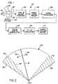
- Figure 2is a diagrammatic representation of a windshield wiper pattern.
- FIG. 1illustrates selected components of a windshield wiper control system 10.
- the wiper system operative componentsare illustrated as portion 12 of Figure 1.
- the wiper systemper se, includes a dc motor 14 that preferably has a variable motor speed responsive to a motor control signal supplied to the motor.
- Wiper blades 16are coupled to and driven by motor 14 through conventional linkage 18.
- Linkage 18preferably moves wiper blades 16 through the wiper pattern according to a motor control signal received in motor 14.
- Arm and blade position indicator 20includes a position sensing device used to determine the position of the wiper blade on the windshield relative to the reversal points of the wipe pattern.
- the position sensing devicepreferably includes a switch operating form a cam or plate, for example, or an optical encoder or magnetic pick-up device that is coupled through suitable electronics for producing an electrical signal indicative of the position of the wiper blade.
- the voltage of the electrical signal from the position sensing deviceis the controlling or important characteristic of the signal.
- a position indicative voltage signalis produced by the signal level circuit illustrated by a block diagram box 24.
- the position indicative voltage signalis processed at signal processing circuitry 26 such that the signal becomes proportional to a desired motor speed, dependent on the position of the viper blade relative to the reversal point or end point of the wiper stroke.
- the determination of the desired motor speeddepends on whether the position of the wiper is within a slow down portion or zone of the viper blade pattern wherein it is desirable for the wiper blade to decelerate prior to reaching the reversal points.
- the angles defining the optimum surface area covered by the slow down portion of the wiper patterncan be determined on a vehicle-by-vehicle basis. The angles at which reduced speed will optimize system performance with respect to noise, angle growth and water expulsion is to be determined for a particular vehicle wiper system by system analysis and experimentation that would be understood by one skilled in the art and, therefore need not be further described.
- the signal processing that occurs at 26preferably includes level shifting and filtering in order to smooth out the characteristics of the voltage signal received from the signal level circuit 24.
- Level shifting and filteringare used, for example to smooth out the effects of abrupt changes in motor speed that may occur as the wiper blade 16 moves through the wiper pattern.
- the duty cycle of the modulated signal produced by modulator 28is preferably variable between 0 volts and a high state voltage that corresponds to maximum viper speed operation.
- the high state voltageis preferably suitable for driving a power semiconductor device such as the gate of a MOSFET.
- dc-dc converter circuit 30outputs a motor control signal that is preferably applied to the armature of a two brush dc motor.
- the armature voltage of motor 14preferably tracks the motor speed control signal and, therefore, the motor speed tends to follow the armature voltage.
- FIG. 2illustrates, in diagrammatic form, viper blade 16 in viper pattern or stroke 34.
- Wiper pattern 34includes a first end 36 and a second end 38. Ends 36 and 38 are the reversal points of the viper pattern.
- the areas indicated at 40 and 42are the slow down portions of the viper pattern wherein the speed of viper blade 16 is reduced prior to reaching a reversal point (36 or 38) of viper pattern 34.
- the illustrated position of viper blade 16corresponds to a condition of maximum acceleration as viper blade 16 moves through viper pattern 34 in the direction of arrow 44.
- the duty cycle of the motor speed control signalis varied such that the motor speed is reduced as blade 16 travels through slow down region 40. Investigations and experimentation reveal that a slow down zone corresponding to an arc angle of between 15 and 30 degrees is most preferable.
- FIG. 2An example of a typical wipe cycle follows. As illustrated in Figure 2, blade 16, moving in the direction of arrow 44, is at maximum speed in the illustrated position. Position sensing element 20 and signal level circuit 24 communicate the location of viper blade 16 to the remainder of system 10. Motor 14 preferably decelerates viper blade 16 at approximately 15 degrees prior to the full out wipe position, reversal point 36. The motor reaches minimum speed immediately adjacent reversal point 36. After reaching reversal point 36, viper blade 16 begins to traverse through the wipe pattern according to direction arrow 48.
- the position of blade 16 illustrated in Figure 2corresponds to the blade approaching maximum speed when moving in the direction of arrow 48.
- a slow down processsimilar to that described above, occurs once blade 16 enters slow down zone 42 approaching reversal point 38.
- this inventionprovides a useful system and methodology for controlling the speed of a windshield viper as a function of the position of the viper relative to the reversal points of the wipe pattern. Further modifications are possible such as changing the size of the slow down zones as a function of viper speed. Other possible embodiments include selectively varying the speed of the viper throughout its stroke.
- the above descriptionis exemplary rather than limiting in nature. The scope and purview of this invention shall be limited only by the appended claims.
Landscapes
- Engineering & Computer Science (AREA)
- Mechanical Engineering (AREA)
- Control Of Direct Current Motors (AREA)
Description
a position indicator for indicating a position ofthe wiper relative to an end of a stroke across thewindshield, wherein said position indicator comprises amoving member that moves in unison with the wiper and aswitch, coupled to said moving member, that is actuatedas function of the position of said moving member tothereby indicate the position of the wiper;
a signal generator, coupled to said positionindicator, for generating a signal indicative of theposition of the wiper; and
a signal processor for processing the positionindicative signal to thereby produce a motor controlsignal that is proportional to a desired motor speed,said motor control signal having a constant frequency andbeing variable as a function of said position of thewiper.
Claims (12)
- A device (10) for controlling the speed of a wiper in avehicle windshield wiper system, comprising:a position indicator (20) for indicating a position ofthe wiper relative to an end of a stroke across thewindshield, wherein said position indicator comprises amoving member that moves in unison with the wiper and aswitch, coupled to said moving member, that is actuatedas a function of the position of said moving member tothereby indicate the position of the wiper;a signal generator (24), coupled to said positionindicator, for generating a signal indicative of theposition of the wiper; anda signal processor (26) for processing the positionindicative signal to thereby produce a motor controlsignal that is proportional to a desired motor speed,said motor control signal having a constant frequency andbeing variable as a function of said position of thewiper, wherein a portion (40, 42) of the wiper strokeadjacent the end (36, 38) of the wiper stroke is defined, and wherein a duty cycle of the motor control signal isvaried such that the wiper speed is reduced relative tothe remainder of the wiper stroke when the position ofthe wiper is within the defined portion of the wiperstroke.
- The device of claim 1, wherein said signal processor (26)comprises a filter for filtering out abrupt changes insaid position indicative signal.
- The device of claim 1 or 2, wherein said signal processor(26) comprises a pulse width modulator (28) forgenerating a signal having a constant frequency and aselectively variable duty cycle, said duty cycle beingvariable between a value equal to zero volts and amaximum state voltage that corresponds to a maximum wiperspeed.
- The device of claim 3, wherein said signal processor (26)further comprises a dc-dc converter coupled to said pulsewidth modulator (28) for producing the motor speedcontrol signal in a form that is interpreted by a motorthat moves the wiper across the windschield.
- A method for controlling the speed of a wiper in avehicle windshield wiper system that includes a dc motor(14) for moving the wiper throughout a wiper stroke along the surface of the windshield, comprising the steps of:(A) determining the location of the wiper relative to anend (36, 38) of the wiper stroke, wherein step (A)is performed by the substeps of generating aposition signal that has a voltage indicative of theposition of the wiper relative to the end of thewiper stroke;(B) defining a portion (40, 42) of the wiper strokeadjacent the end (36, 38) of the wiper strokewherein the wiper speed is reduced relative to theremainder of the stroke;(c) defining a wiper slow down condition when thelocation from step (A) is within the portion fromstep (B); and(D) varying a duty cycle of a motor speed control signalthat is supplied to the dc motor (14) when thecondition in step (C) is met to thereby control thespeed of the wiper.
- The method of claim 5, wherein step (B) is performed bythe substeps of determining a first relationship betweenan average wiper speed and the total travel of the wiperthrough the stroke, determining a second relationship between an average wiper speed and a desired amount oflateral water expulsion from the windshield, andcalculating an amount of the wiper stroke thatcorresponds to preselected amounts of water expulsionwhile permitting wiper slow down as the wiper approachesthe end (36, 38) of the stroke, using said first andsecond relationships.
- The method of claim 5, wherein step (B) is performed bythe substeps of determining a first relationship betweenan average wiper speed and the total travel of the wiperthrough the stroke, determining a second relationshipbetween an average wiper speed and noise caused by thewiper reaching an end of the stroke, and calculating anamount of the wiper stroke that corresponds to reducingnoise caused by the wiper reaching the end (36, 38) ofthe stroke, using the first and second relationship.
- The method of claim 5, wherein step (B) is performed bythe substeps of determining a first relationship betweenan average wiper speed and the total travel of the wiperthrough the stroke, determining a second relationshipbetween an average wiper speed and an undesirable amountof deformation of the wiper stroke, and calculating anamount of the wiper stroke that is required to compensatefor the undesirable deformation, using the first andsecond relationships.
- The method of one of claims 5 to 8, wherein step (D) isperformed by the substeps of generating a motor speedcontrol signal that is proportional to a desired motorspeed and modulating the motor speed control signal,using pulse width modulation, to thereby generate acontrol signal having a constant frequency and aselectively variable duty cycle.
- The method of claim 9, wherein the duty cycle of thecontrol signal is used to directly control the speed ofthe wiper.
- The method of one of claims 5 to 10, wherein step (D) isperformed by the substeps of processing the positionsignal to thereby produce a motor control signalproportional to a desired motor speed.
- The method of claim 11, where step (D) is performed bythe further substeps of modulating the motor controlsignal, using pulse width modulation, to thereby generatea motor speed signal having a constant frequency and aselectively variable duty cycle.
Applications Claiming Priority (3)
| Application Number | Priority Date | Filing Date | Title |
|---|---|---|---|
| US08/333,822US5506483A (en) | 1994-11-03 | 1994-11-03 | Windshield wiper system incorporating a variable speed DC motor |
| US333822 | 1994-11-03 | ||
| PCT/US1995/012103WO1996014225A1 (en) | 1994-11-03 | 1995-09-25 | Windshield wiper system incorporating a variable speed dc motor |
Publications (2)
| Publication Number | Publication Date |
|---|---|
| EP0787082A1 EP0787082A1 (en) | 1997-08-06 |
| EP0787082B1true EP0787082B1 (en) | 2003-03-05 |
Family
ID=23304398
Family Applications (1)
| Application Number | Title | Priority Date | Filing Date |
|---|---|---|---|
| EP95933200AExpired - LifetimeEP0787082B1 (en) | 1994-11-03 | 1995-09-25 | Windshield wiper system incorporating a variable speed dc motor |
Country Status (5)
| Country | Link |
|---|---|
| US (1) | US5506483A (en) |
| EP (1) | EP0787082B1 (en) |
| JP (1) | JPH10508558A (en) |
| DE (1) | DE69529834T2 (en) |
| WO (1) | WO1996014225A1 (en) |
Cited By (1)
| Publication number | Priority date | Publication date | Assignee | Title |
|---|---|---|---|---|
| CN103661276A (en)* | 2014-01-03 | 2014-03-26 | 安徽江淮汽车股份有限公司 | Wiper protection control method and system |
Families Citing this family (26)
| Publication number | Priority date | Publication date | Assignee | Title |
|---|---|---|---|---|
| US5654617A (en)* | 1995-09-18 | 1997-08-05 | Mills; Manual D. | Windshield wiper controller and method |
| FR2745540B1 (en)* | 1996-02-29 | 1998-04-10 | Valeo Systemes Dessuyage | DEVICE FOR CONTROLLING A VEHICLE WINDOW WIPING SYSTEM |
| DE19732520A1 (en)* | 1997-07-29 | 1999-02-04 | Itt Mfg Enterprises Inc | Windshield wiper |
| DE19741630B4 (en) | 1997-09-20 | 2006-04-27 | Volkswagen Ag | wiper device |
| DE19746375A1 (en)* | 1997-10-21 | 1999-04-22 | Itt Mfg Enterprises Inc | Control circuit for windscreen washers |
| US6232603B1 (en) | 1998-10-29 | 2001-05-15 | Kelsey-Hayes Co. | Rain sensor operation on solar reflective glass |
| US5990647A (en)* | 1998-10-29 | 1999-11-23 | Kelsey-Hayes Co. | Embedded self-test for rain sensors |
| JP4005256B2 (en)* | 1999-03-05 | 2007-11-07 | アスモ株式会社 | Wiper control device |
| US6393653B1 (en) | 1999-11-19 | 2002-05-28 | Valeo Electrical Systems, Inc. | Windshield wiper inertia absorption apparatus and method |
| US6400111B1 (en)* | 2000-01-31 | 2002-06-04 | General Electric Company | Locomotive electric windshield wiper system utilizing DC-DC electronic convertor power source |
| US6404150B1 (en)* | 2000-06-27 | 2002-06-11 | General Motors Corporation | Accessory motor drive power supply system for an electric vehicle |
| DE10035042A1 (en)* | 2000-07-19 | 2002-01-31 | Bosch Gmbh Robert | Wiper device for a window |
| AU2001290269A1 (en)* | 2000-09-28 | 2002-04-15 | Helios Co., Ltd. | Wiper drive signal generating device, wiper drive signal generating method and vehicle |
| FR2818600B1 (en)* | 2000-12-21 | 2003-03-07 | Valeo Systemes Dessuyage | METHOD FOR CONTROLLING A WIPING MOTOR, CONTROLLER IMPLEMENTING THE METHOD AND WIPING DEVICE USING SUCH A CONTROLLER |
| EP1663740A4 (en)* | 2003-09-15 | 2010-04-14 | Magna Closures Inc | Reversing-motor windshield wiper system |
| JP4127251B2 (en)* | 2004-07-23 | 2008-07-30 | 株式会社デンソー | DC motor rotation information detector |
| FR2896925B1 (en)* | 2006-01-31 | 2008-04-18 | Valeo Systemes Dessuyage | PROTECTION METHOD FOR REVERSIBLE ELECTRIC MOTOR |
| FR2926516B1 (en)* | 2008-01-18 | 2010-06-04 | Peugeot Citroen Automobiles Sa | AUTOMOTIVE VEHICLE ICE WIPING DEVICE HAVING DIFFERENT SCAN FREQUENCY WIPING ZONES |
| FR2947785B1 (en)* | 2009-07-07 | 2011-11-11 | Eurocopter France | METHOD FOR CLEANING A WINDSHIELD OF A VEHICLE, AND WINDSHIELD USING THE SAME |
| CN101920691B (en)* | 2010-09-10 | 2012-01-25 | 王洪紫龙 | Wiper protection device and control method thereof |
| FR2988353B1 (en)* | 2012-03-21 | 2014-05-16 | Valeo Systemes Dessuyage | METHOD AND DEVICE FOR CONTROLLING A MOTOR VEHICLE WIPER ENGINE |
| JP6239507B2 (en)* | 2012-07-12 | 2017-11-29 | 株式会社ミツバ | Wiper control method and wiper control device |
| JP5981973B2 (en)* | 2014-09-30 | 2016-08-31 | 富士重工業株式会社 | Vehicle wiper device |
| US10040425B2 (en) | 2016-11-10 | 2018-08-07 | Ford Global Technologies, Llc | System for detecting windshield wiper noise and related methods |
| US10068388B2 (en) | 2016-11-10 | 2018-09-04 | Ford Global Technologies Llc | Automated system for suggesting wiper replacement |
| FR3098169B1 (en)* | 2019-07-04 | 2021-12-31 | Valeo Systemes Dessuyage | Wiper device for a motor vehicle, motor vehicle and method for controlling an electric motor. |
Family Cites Families (22)
| Publication number | Priority date | Publication date | Assignee | Title |
|---|---|---|---|---|
| DE3248118A1 (en)* | 1982-12-24 | 1984-06-28 | SWF-Spezialfabrik für Autozubehör Gustav Rau GmbH, 7120 Bietigheim-Bissingen | WINDOW WIPER SYSTEM FOR MOTOR VEHICLES |
| US4578591A (en)* | 1984-10-25 | 1986-03-25 | United Technologies Automotive, Inc. | Control circuit for automotive accessory system |
| US4665488A (en)* | 1984-12-06 | 1987-05-12 | General Motors Corporation | Synchronizing wiper control |
| US4663575A (en)* | 1986-02-21 | 1987-05-05 | United Technologies Automotive, Inc. | Speed control for a window wiper system |
| US4705997A (en)* | 1986-02-21 | 1987-11-10 | United Technologies Automotive, Inc. | Bidirectional motor drive circuit |
| US4705998A (en)* | 1987-02-09 | 1987-11-10 | Steven Alpert | Automatic window wiper control |
| US5397991A (en)* | 1988-07-13 | 1995-03-14 | Electronic Development Inc. | Multi-battery charging system for reduced fuel consumption and emissions in automotive vehicles |
| US5216341A (en)* | 1988-12-19 | 1993-06-01 | Fujitsu Ten Limited | Windshield wiper control apparatus |
| US4866357A (en)* | 1988-12-19 | 1989-09-12 | Ford Motor Company | Windshield wiper and control system |
| DE3941905A1 (en)* | 1988-12-19 | 1990-06-21 | Fujitsu Ten Ltd | WINDOW WIPER CONTROL DEVICE |
| US4956591A (en)* | 1989-02-28 | 1990-09-11 | Donnelly Corporation | Control for a moisture sensor |
| US4916374A (en)* | 1989-02-28 | 1990-04-10 | Donnelly Corporation | Continuously adaptive moisture sensor system for wiper control |
| DE3939938A1 (en)* | 1989-12-02 | 1991-06-06 | Vdo Schindling | DEVICE FOR CONTROLLING A WIPER |
| US5059877A (en)* | 1989-12-22 | 1991-10-22 | Libbey-Owens-Ford Co. | Rain responsive windshield wiper control |
| DE4000735A1 (en)* | 1990-01-12 | 1991-07-18 | Vdo Schindling | METHOD AND ARRANGEMENT FOR CONTROLLING A WIPER |
| DE4000736A1 (en)* | 1990-01-12 | 1991-07-18 | Vdo Schindling | METHOD AND ARRANGEMENT FOR CONTROLLING A WIPER |
| JPH0424148A (en)* | 1990-05-18 | 1992-01-28 | Nissan Motor Co Ltd | Wiper drive control device |
| US5355061A (en)* | 1992-01-24 | 1994-10-11 | Grimes Aerospace Company | Windshield wiper system |
| US5252897A (en)* | 1992-04-13 | 1993-10-12 | General Motors Corporation | Dual motor wiper control |
| US5404085A (en)* | 1992-07-10 | 1995-04-04 | Rosemount Aerospace, Inc. | Multifunction aircraft windscreen wiper control system |
| US5254916A (en)* | 1992-07-31 | 1993-10-19 | Sgs-Thomson Microelectronics, Inc. | Windshield wiper speed and delay control |
| US5386111A (en)* | 1993-10-08 | 1995-01-31 | Zimmerman; H. Allen | Optical detection of water droplets using light refraction with a mask to prevent detection of unrefracted light |
- 1994
- 1994-11-03USUS08/333,822patent/US5506483A/ennot_activeExpired - Lifetime
- 1995
- 1995-09-25JPJP8515291Apatent/JPH10508558A/enactivePending
- 1995-09-25WOPCT/US1995/012103patent/WO1996014225A1/enactiveIP Right Grant
- 1995-09-25EPEP95933200Apatent/EP0787082B1/ennot_activeExpired - Lifetime
- 1995-09-25DEDE69529834Tpatent/DE69529834T2/ennot_activeExpired - Lifetime
Cited By (1)
| Publication number | Priority date | Publication date | Assignee | Title |
|---|---|---|---|---|
| CN103661276A (en)* | 2014-01-03 | 2014-03-26 | 安徽江淮汽车股份有限公司 | Wiper protection control method and system |
Also Published As
| Publication number | Publication date |
|---|---|
| EP0787082A1 (en) | 1997-08-06 |
| JPH10508558A (en) | 1998-08-25 |
| US5506483A (en) | 1996-04-09 |
| WO1996014225A1 (en) | 1996-05-17 |
| DE69529834T2 (en) | 2003-08-28 |
| DE69529834D1 (en) | 2003-04-10 |
Similar Documents
| Publication | Publication Date | Title |
|---|---|---|
| EP0787082B1 (en) | Windshield wiper system incorporating a variable speed dc motor | |
| US4866357A (en) | Windshield wiper and control system | |
| EP2873568B1 (en) | Wiper control method and wiper control device | |
| US5355061A (en) | Windshield wiper system | |
| US6249098B1 (en) | Wiper control apparatus and method capable of variably adjusting wiper blade motion | |
| US6946810B2 (en) | Windscreen wiper system comprising two opposed wipers | |
| EP0793157A3 (en) | Automatic door controller | |
| WO2011098184A1 (en) | Wiper motor control | |
| US20030020422A1 (en) | Windscreen wiper device for wiping windscreens | |
| US5860185A (en) | Reversing wiper motor system | |
| CN108698564B (en) | Windscreen wiper control device | |
| US5642026A (en) | Windshield wiper system having reduced wipe speed at reversal points using variable frequency induction motor control | |
| US5826295A (en) | Windscreen wipers | |
| EP0405744A2 (en) | Vehicle window wipers with dynamic symmetrical overlap | |
| CA2398013C (en) | Method for controlling the run-up of a conveyor belt and drive device for a conveyor belt | |
| KR20000023243A (en) | Windshield wiper for an automobile | |
| US6359407B1 (en) | Windshield wiper device | |
| CN1387485A (en) | Wiper device for wiping window and method for operating same | |
| US7019477B2 (en) | Method for controlling a wiper motor | |
| US6690130B2 (en) | Windshield wiper system | |
| JP3910295B2 (en) | Control method and control device for counter-wiping wiper device | |
| KR101869841B1 (en) | Wiper drive | |
| SU1283313A1 (en) | System for controlling the working process of earth-moving and handling machine | |
| JP2002264772A (en) | Control method for opposing wiping type wiper device | |
| JP2002274331A (en) | Control method for opposed wiping type wiper device |
Legal Events
| Date | Code | Title | Description |
|---|---|---|---|
| PUAI | Public reference made under article 153(3) epc to a published international application that has entered the european phase | Free format text:ORIGINAL CODE: 0009012 | |
| 17P | Request for examination filed | Effective date:19970603 | |
| AK | Designated contracting states | Kind code of ref document:A1 Designated state(s):DE GB | |
| 17Q | First examination report despatched | Effective date:19970919 | |
| RIN1 | Information on inventor provided before grant (corrected) | Inventor name:STAKER, WILLIAM, C. Inventor name:SURIANO, JOHN, R. Inventor name:MCCANN, ROY, A. | |
| GRAH | Despatch of communication of intention to grant a patent | Free format text:ORIGINAL CODE: EPIDOS IGRA | |
| GRAH | Despatch of communication of intention to grant a patent | Free format text:ORIGINAL CODE: EPIDOS IGRA | |
| GRAA | (expected) grant | Free format text:ORIGINAL CODE: 0009210 | |
| AK | Designated contracting states | Designated state(s):DE GB | |
| REG | Reference to a national code | Ref country code:GB Ref legal event code:FG4D | |
| REF | Corresponds to: | Ref document number:69529834 Country of ref document:DE Date of ref document:20030410 Kind code of ref document:P | |
| PLBE | No opposition filed within time limit | Free format text:ORIGINAL CODE: 0009261 | |
| STAA | Information on the status of an ep patent application or granted ep patent | Free format text:STATUS: NO OPPOSITION FILED WITHIN TIME LIMIT | |
| 26N | No opposition filed | Effective date:20031208 | |
| PGFP | Annual fee paid to national office [announced via postgrant information from national office to epo] | Ref country code:DE Payment date:20140911 Year of fee payment:20 | |
| PGFP | Annual fee paid to national office [announced via postgrant information from national office to epo] | Ref country code:GB Payment date:20140917 Year of fee payment:20 | |
| REG | Reference to a national code | Ref country code:DE Ref legal event code:R071 Ref document number:69529834 Country of ref document:DE | |
| REG | Reference to a national code | Ref country code:GB Ref legal event code:PE20 Expiry date:20150924 | |
| PG25 | Lapsed in a contracting state [announced via postgrant information from national office to epo] | Ref country code:GB Free format text:LAPSE BECAUSE OF EXPIRATION OF PROTECTION Effective date:20150924 |