EP0786204B1 - Device for fitting birds with a transponder - Google Patents
Device for fitting birds with a transponderDownload PDFInfo
- Publication number
- EP0786204B1 EP0786204B1EP96119743AEP96119743AEP0786204B1EP 0786204 B1EP0786204 B1EP 0786204B1EP 96119743 AEP96119743 AEP 96119743AEP 96119743 AEP96119743 AEP 96119743AEP 0786204 B1EP0786204 B1EP 0786204B1
- Authority
- EP
- European Patent Office
- Prior art keywords
- transponder
- shaped
- wing
- sides
- leg
- Prior art date
- Legal status (The legal status is an assumption and is not a legal conclusion. Google has not performed a legal analysis and makes no representation as to the accuracy of the status listed.)
- Expired - Lifetime
Links
- 244000144977poultrySpecies0.000claimsdescription14
- 210000000988bone and boneAnatomy0.000claimsdescription8
- 210000000078clawAnatomy0.000claimsdescription6
- 239000004020conductorSubstances0.000claims2
- 210000002414legAnatomy0.000description62
- 241001465754MetazoaSpecies0.000description14
- 239000011521glassSubstances0.000description6
- 210000002683footAnatomy0.000description5
- 238000003780insertionMethods0.000description4
- 230000037431insertionEffects0.000description4
- 238000005452bendingMethods0.000description3
- 239000000463materialSubstances0.000description3
- 238000000034methodMethods0.000description3
- 210000000689upper legAnatomy0.000description3
- 241000272201ColumbiformesSpecies0.000description2
- 230000008859changeEffects0.000description2
- 238000011161developmentMethods0.000description2
- 230000018109developmental processEffects0.000description2
- 238000002347injectionMethods0.000description2
- 239000007924injectionSubstances0.000description2
- 238000001746injection mouldingMethods0.000description2
- 238000002372labellingMethods0.000description2
- 230000008569processEffects0.000description2
- 238000003307slaughterMethods0.000description2
- 239000000243solutionSubstances0.000description2
- 230000007704transitionEffects0.000description2
- 241000283690Bos taurusSpecies0.000description1
- 241000272205Columba liviaSpecies0.000description1
- 241001295925GegenesSpecies0.000description1
- 230000009471actionEffects0.000description1
- 239000000853adhesiveSubstances0.000description1
- 238000004026adhesive bondingMethods0.000description1
- 230000001070adhesive effectEffects0.000description1
- 210000003423ankleAnatomy0.000description1
- 230000006399behaviorEffects0.000description1
- 238000009395breedingMethods0.000description1
- 230000001488breeding effectEffects0.000description1
- 230000006378damageEffects0.000description1
- 238000013461designMethods0.000description1
- 238000011156evaluationMethods0.000description1
- 238000000605extractionMethods0.000description1
- 238000009313farmingMethods0.000description1
- 230000004634feeding behaviorEffects0.000description1
- 208000037824growth disorderDiseases0.000description1
- 239000007943implantSubstances0.000description1
- 238000007373indentationMethods0.000description1
- 238000009434installationMethods0.000description1
- 230000002427irreversible effectEffects0.000description1
- 239000003550markerSubstances0.000description1
- 235000013372meatNutrition0.000description1
- 239000002184metalSubstances0.000description1
- 239000012811non-conductive materialSubstances0.000description1
- 238000005457optimizationMethods0.000description1
- 210000002976pectoralis muscleAnatomy0.000description1
- 229920001639plastic brandPolymers0.000description1
- 230000000384rearing effectEffects0.000description1
- 230000033764rhythmic processEffects0.000description1
- 238000000926separation methodMethods0.000description1
- 239000007921spraySubstances0.000description1
- 230000008719thickeningEffects0.000description1
- 230000036962time dependentEffects0.000description1
- 238000012549trainingMethods0.000description1
- 238000003466weldingMethods0.000description1
- 229910000859α-FeInorganic materials0.000description1
Images

Classifications
- A—HUMAN NECESSITIES
- A01—AGRICULTURE; FORESTRY; ANIMAL HUSBANDRY; HUNTING; TRAPPING; FISHING
- A01K—ANIMAL HUSBANDRY; AVICULTURE; APICULTURE; PISCICULTURE; FISHING; REARING OR BREEDING ANIMALS, NOT OTHERWISE PROVIDED FOR; NEW BREEDS OF ANIMALS
- A01K11/00—Marking of animals
- A01K11/001—Ear-tags
- A01K11/004—Ear-tags with electronic identification means, e.g. transponders
- A—HUMAN NECESSITIES
- A01—AGRICULTURE; FORESTRY; ANIMAL HUSBANDRY; HUNTING; TRAPPING; FISHING
- A01K—ANIMAL HUSBANDRY; AVICULTURE; APICULTURE; PISCICULTURE; FISHING; REARING OR BREEDING ANIMALS, NOT OTHERWISE PROVIDED FOR; NEW BREEDS OF ANIMALS
- A01K11/00—Marking of animals
- A01K11/006—Automatic identification systems for animals, e.g. electronic devices, transponders for animals
- A—HUMAN NECESSITIES
- A01—AGRICULTURE; FORESTRY; ANIMAL HUSBANDRY; HUNTING; TRAPPING; FISHING
- A01K—ANIMAL HUSBANDRY; AVICULTURE; APICULTURE; PISCICULTURE; FISHING; REARING OR BREEDING ANIMALS, NOT OTHERWISE PROVIDED FOR; NEW BREEDS OF ANIMALS
- A01K35/00—Marking poultry or other birds
- Y—GENERAL TAGGING OF NEW TECHNOLOGICAL DEVELOPMENTS; GENERAL TAGGING OF CROSS-SECTIONAL TECHNOLOGIES SPANNING OVER SEVERAL SECTIONS OF THE IPC; TECHNICAL SUBJECTS COVERED BY FORMER USPC CROSS-REFERENCE ART COLLECTIONS [XRACs] AND DIGESTS
- Y10—TECHNICAL SUBJECTS COVERED BY FORMER USPC
- Y10T—TECHNICAL SUBJECTS COVERED BY FORMER US CLASSIFICATION
- Y10T24/00—Buckles, buttons, clasps, etc.
- Y10T24/34—Combined diverse multipart fasteners
- Y10T24/3427—Clasp
- Y10T24/3428—Clasp having pivoted members
- Y—GENERAL TAGGING OF NEW TECHNOLOGICAL DEVELOPMENTS; GENERAL TAGGING OF CROSS-SECTIONAL TECHNOLOGIES SPANNING OVER SEVERAL SECTIONS OF THE IPC; TECHNICAL SUBJECTS COVERED BY FORMER USPC CROSS-REFERENCE ART COLLECTIONS [XRACs] AND DIGESTS
- Y10—TECHNICAL SUBJECTS COVERED BY FORMER USPC
- Y10T—TECHNICAL SUBJECTS COVERED BY FORMER US CLASSIFICATION
- Y10T24/00—Buckles, buttons, clasps, etc.
- Y10T24/44—Clasp, clip, support-clamp, or required component thereof
- Y10T24/44291—Clasp, clip, support-clamp, or required component thereof including pivoted gripping member
- Y10T24/44325—Clasp, clip, support-clamp, or required component thereof including pivoted gripping member having three or more pivotally connected gripping members
Definitions
- the inventionrelates to a device according to the preamble of claim 1.
- EP 0485 039 A1discloses a ring for fitting around the leg of an animal, which is wavy in cross section over at least part of its circumference runs. As a result, he should, without causing growth disorders, deal with the To be able to stretch the leg. In a thickening of the undulating Structure is parallel to the ring axis a cavity for receiving a rod-shaped Transponders provided. Such an elastically widening, corrugated ring in practice, however, is easily lost again from the animal's leg.
- the inventionis based on the foot rings known for poultry - based on the technical problem, a poultry brand with electronic To create transponders that the chicks already in the first days of life without disrupt their growth, are placed around a wing bone - out but then later without the need to completely remove the brand again the transponder can be recovered and then used again (namely in a new wing brand).
- the known, bendable around the wing bone of the poultry Metal streak poultry brand with embossed or printed Ident information replaced by at least two-leg U, V, Z or W-shaped Wing brand made of electrically non-conductive material attached to one of their Legtakes the high-frequency transponder and that by means of a barb locking pin can be placed around the wing bone.
- the tubular encapsulated transpondercan be non-positive or positive in a trough-shaped Well or be held in a pocket-shaped pocket, which at Plastic injection molding can be trained at the same time.
- the barb locking pincan be molded onto a free leg end or as a separate one Additional part can be inserted through its perforation.
- the only one in the tub or Bag pinched and expensive compared to the injection molding wing brand as well as for A transponder registered to a certain breedercan then be completed removed from the mast phase from its plastic holder and ready for re-assembly be kept ready for a new generation.
- U or V-shaped Wing mark 11is injection-molded in one piece from rigid plastic.
- Your relatively rigid legs 12are resilient to one another in the area of the yoke 13 connected, for which the thickness of the leg cross section here to one Bending or predetermined breaking area 14 is weakened.
- the legs 12run in a substantially circular molded plates 16 from.
- leg 12 located in front of the wingcan be designed as an information carrier 20 on the outside be, for example with a surface finish for gluing or printing be equipped with visually recordable information (such as can be displayed alphanumerically or as a barcode; not taken into account in the drawing).
- leg 12 'equipped as a transponder carrier.
- a transponder 21(FIG. 2; not shown in FIG. 1) is preferably used in the In the form of a small glass tube designed for carcass injection, in which a memory chip resonates with a defined one Interrogated radio frequency tuned, subminiature ferrite core coil connected is.
- a query money of this frequencyinduces the electrical in the transponder 21 Energy for reading the memory with the result that the query field in the Rhythm of the stored identification information is damped (modulated).
- a Demodulation of this time-dependent attenuationdelivers in the reader, from which the radiofrequency field is emitted, a decodable representation of the binary-coded identification information of the transponder just captured by the query money 21 to identify the animal, such as the chick, with this tag 11 is equipped.
- the glass tube of the transponder 21can be directly on the inner or outer Surface of a leg 12 'carrying the transponder can be glued on. Installation is easier and, above all, more reliable if it is in the transponder leg 12 'a trough-shaped receptacle extending in the longitudinal direction thereof 22 is formed, which is also about the material thickness of this leg 12 ' can bulge outwards, as taken into account in FIG. 1. In this tub-shaped Recording 22 can then easily the glass tube of the transponder 21 inserted and fixed positively or non-positively therein.
- the non-positive Fixingcan be done by an adhesive, or by over-welding about by means of a wrapping sheet as a cover 23, which on the inside of the Transponder legs 12 ', overlapping the trough-shaped receptacle 22, are integrally formed is or is being hung up. Handling is particularly easy if such a thin, elongated wrapper in the form of a spray skin along or tongue-shaped on the transverse side to the inside of the transponder leg 12 'in the neighborhood the receptacle 22 is articulated (thus molded as a flap) and then after the insertion of the transponder 21 only pivoted over it and at the free end needs to be glued or welded, as taken into account in FIG. 1.
- a pocket-shaped receptacle 22is expedient for this case Kind of a blind hole (Fig. 2), which then on the outside of the transponder leg 12 'alongside arranged, preferably molded, and expediently accessible is that it is at one end for inserting the transponder tube 21 is open.
- sacklock-shaped receptacle can lie opposite 22can also be equipped with a small opening 24 in order to have one Ejection mandrel for pushing the transponder 21 out of its opposite one To be able to introduce recording 22.
- the locking pin 17is not integral part of the wing mark 11, but formed separately. His barb tip 18 can by perforated plates 16 on the leg ends 15th put through and right there, or with an opposite one Perforated disk 25, be locked. A circumferential collar delimits on the insertion side 26 on pin 17, the insertion process in the with folded legs 12-12 'aligned holes 19.
- the locking pin 17is cut and / or designed as a predetermined breaking point tapered area 14 in yoke 13 broken or also cut open, so that in any case the two are no longer firmly connected Let legs 12, 12 'lift off on both sides of the wing.
- the glass tube transponder 21becomes the trough-shaped or blind hole-shaped receptacle 22 lifted out in the transverse direction or pushed out in the longitudinal direction and can directly serve to equip another wing mark 11: while if a wing mark 11 is reused, it will only be disinfected overall ought to.
- the mark 11 that is still openis the linear succession of three legs, namely a cover leg 12 between an inner leg 12 and a later later external transponder leg 12 '.
- the latterare at the two ends of the cover leg 12 connected to each other by means of film hinges as the tapered bending areas 14, preferably injection molded in one piece from light plastic material.
- the wing bone of the poultry to be equipped with such a mark 11 according to FIG. 3is bordered between the inner leg 12 and the cover leg 12 ′′ adjoining it and thus does not come into contact with the transponder area.
- the locking washer 25, which irreversibly receives the barb tip 18 of the slender-conical locking pin 17,is in the vicinity of the end of the covering leg 12 opposite the hinge region 14 arranged or molded. From the view in Fig. 4 it can be seen that the hole 19 in the locking disc 25, which irreversibly receives the barb tip 18 of the slim-cone-shaped locking pin 17, is radially slotted to facilitate the insertion of the barb tip 18 and then in addition to that form fit to exert a barbed force fit on the shaft of the locking pin 17.
- the tube transponder 21is again in a trough-shaped bulge Transponder leg 12 ', parallel to its longitudinal extent, inserted, wherein the closure of this receptacle 22 by means of the two outer legs 12/12 'bridging inner leg 12' '.
- the arrangementundergoes a non-positive, re-opening Latch locking by means of lateral claws 27, that of the locking disk 25 opposite to the cover leg 12 '' are formed laterally and locally corresponding lateral indentations 28 in addition to the receiving trough 22 in Intervene transponder leg 12 '.
- This locking bracketis stabilized by a horseshoe-shaped between the two claws 27 along the adjacent end of the cover leg 12 '' extending collar 29 into which the free Leg end 15 'when folding these two legs 12' '- 12' nestles in a form-fitting manner, thereby facing its hinge region 14 to be supported positively in the longitudinal and transverse directions and thus the locking connection to stabilize.
- the spring action for the elastically deformable Locking claws 27are still to be improved, including those on the longitudinal median plane of the Legs 12 '' and thus ends to be pointed towards each other Cover leg 12 '' provided.
- a cavity 31is also formed, into which the transponder receptacle is closed 22 the locking disk formed under the cover leg 12 '' 25 immersed and thus deep enough for the engagement of the locking pin tip 18 is designed.
- a cover leg 12which can be reversibly locked with the transponder leg 12 ' with the mark 11 still open in the longitudinal direction between the transponder leg 12 'and a rear holding leg (12), which in turn on its free leg end 15 by means of a barbed pin 17 - against latching - enclosing a wing bone with the cover Thigh 12 is positively connectable.
Landscapes
- Life Sciences & Earth Sciences (AREA)
- Environmental Sciences (AREA)
- Birds (AREA)
- Animal Husbandry (AREA)
- Biodiversity & Conservation Biology (AREA)
- Zoology (AREA)
- Radar Systems Or Details Thereof (AREA)
- Processing Of Meat And Fish (AREA)
Description
Translated fromGermanDie Erfindung betrifft eine Einrichtung gemäß dem Oberbegriff des Anspruches 1.The invention relates to a device according to the preamble of claim 1.
Zur Ausstattung von Geflügel mit elektronischen passiven Hochfrequenz-Transpondernist es aus dem Beitrag
Im Taubensport ist es bekannt, Brieftauben mit Fußringen auszustatten, in die einIdent-Transponder eingebaut ist, um die Ankunftszeit der Taube im Heimatschlagohne manuelle Eingriffserfodernisse automatisch erfassen und für die Wettkampfauswertungbereitstellen zu können. Besonders bei Küken ist aber ein dauerhaftesAnlegen von Fußringen und insbesondere der Einsatz der vergleichsweise großenTransponder-Fußringe kaum möglich, weil in den ersten Lebenstagen des Geflügelsdie Füße noch so klein und weich sind, daß der Ring leicht wieder abgestreiftwerden könnte; während andererseits in den ersten Lebenswochen der Umfang derGeflügelbeine derart rasch zunimmt, daß ein über dem Fuß enger anliegender Ringden Wachstumprozeß beeinträchtigen würde. Andererseits ist es in der gewerblichenTierhaltung gerade auch für erst mehrtägige Küken von großem Interesse fürdie Optimierung des Aufzuchtergebnisses, schon möglichst früh z.B. die Veränderung des Futterverhaltens und der Nestgewohnheiten einzelner Tiere beobachtenund auswerten zu können.In pigeon racing it is known to equip carrier pigeons with foot rings into which oneIdent transponder is built in to the arrival time of the pigeon in the home beatautomatically record without manual intervention and for the competition evaluationto be able to provide. Especially with chicks is a permanent onePut on foot rings and especially the use of the comparatively large onesTransponder ankle rings hardly possible because in the first days of life of the poultrythe feet are so small and soft that the ring is easily stripped offcould be; while on the other hand in the first weeks of life the extent ofPoultry legs increase so rapidly that a ring that fits snugly over the footwould affect the growth process. On the other hand, it is in the commercialAnimal husbandry is of great interest to chicks that are only for several daysthe optimization of the rearing result, e.g. as early as possible the changeobserve the feeding behavior and nesting habits of individual animalsand to be able to evaluate.
Aus der EP 0485 039 A1 ist ein Ring zum Anlegen um das Bein eines Tieres bekannt,der über wenigstens einen Teil seines Umfangs im Querschnitt wellenförmigverläuft. Dadurch soll er, ohne Wachstumsstörungen hervorzurufen, sich mit demAnwachsen des Beines strecken zu können. In eine Verdickung der wellenförmigenStruktur ist parallel zur Ringachse ein Hohlraum zur Aufnahme eines stabförmigenTransponders vorgesehen. Ein solcher elastisch sich aufweitender, gewellter Ringgeht aber in der Praxis sehr leicht vom Bein des Tieres wieder verloren.EP 0485 039 A1 discloses a ring for fitting around the leg of an animal,which is wavy in cross section over at least part of its circumferenceruns. As a result, he should, without causing growth disorders, deal with theTo be able to stretch the leg. In a thickening of the undulatingStructure is parallel to the ring axis a cavity for receiving a rod-shapedTransponders provided. Such an elastically widening, corrugated ringin practice, however, is easily lost again from the animal's leg.
Dagegen ist es zur Viehauszeichnung mittels massiver Ohrmarken aus der WO95/04455 A1 bekannt, bei einem zweischenklig-U-förmigen Gebilde mit biegeweichemJoch diesem gegenüber an den beiden freien Schenkelstirnenden, quer zurLängserstreckung der Schenkel orientiert, einerseits einen Raststift und andererseitseinen Rastring vorzusehen. Der Stift weist in seiner Längsrichtung - und damitquer zur Orientierung der Schenkel - einen verschlossenen Hohlraum zur Aufnahmeeines stabförmigen passiven Hochfrequenz-Transponders auf. Das bedingt einenganz erheblichen Durchmesser des Stiftes; und dennoch muß dieser dicke amSchaft profilierte Stift zum Anlegen der Ohrmarke durch das Ohr eines Tieres gebohrtwerden, um mit seiner freien Spitze danach das Loch im Rastring durchstoßenund in einen dahinter gelegenen, hutförmig auftragenden Raum hineinstoßenzu können. Das geschwächte Joch, dem Raststift gegenüber als biegsame Verbindungzwischen den beiden Schenkeln ausgelegt, ist als Sollbruchstelle für den Fallkonzipiert, daß das Ohr eines Tieres sich mit diesem geschlossenen U-förmigenGebilde in einem Hindernis verfängt. Beiläufig ist in jener Publikation erwähnt, daßder Transponder nicht wie allein dargestellt und beschrieben zwingend im Verriegelungs-Raststiftangeordnet sein muß, sondern auch an beliebiger anderer Stelle jenereinteiligen elektronischen Ohrmarke vorgesehen sein kann. Der Einschluß des Transponders (insbesondere in den Verriegelungsstift) hat aber stets zur Folge, daßer nicht ohne weiteres aus der Ohrmarke zurückgewonnen werden kann.In contrast, it is for cattle labeling using massive ear tags from the WO95/04455 A1 known, in a two-leg U-shaped structure with flexibleYoke opposite this on the two free ends of the thighs, transverse toLongitudinal orientation of the legs, on the one hand a locking pin and on the other handto provide a locking ring. The pen points in its longitudinal direction - and thereforetransverse to the orientation of the legs - a closed cavity for receivingof a rod-shaped passive high-frequency transponder. That requires onevery considerable diameter of the pin; and yet this fat one mustShank profiled pin for applying the ear tag drilled through the ear of an animalto then pierce the hole in the locking ring with its free tipand push into a hat-shaped room behindto be able to. The weakened yoke, opposite the locking pin as a flexible connectiondesigned between the two legs is as a predetermined breaking point for the casedesigned to make an animal's ear U-shaped with this closedEntangled in an obstacle. Incidentally, that publication mentions thatthe transponder is not necessarily shown and described in the locking pinmust be arranged, but also anywhere else thatone-piece electronic ear tag can be provided. The inclusion of theTransponders (especially in the locking pin) always has the consequence thatit cannot be easily recovered from the ear tag.
Der Erfindung liegt jedoch - ausgehend von den für Geflügel bekannten Fußringen- die technische Problematik zugrunde, eine Geflügelmarke mit elektronischemTransponder zu schaffen, die schon den Küken in den ersten Lebenstagen, ohnederen Wachstum zu stören, um einen Flügelknochen herum angelegt werden -ausder aber dann später ohne das Erfordernis, die Marke wieder vollständig abnehmenzu müssen, der Transponder rückgewonnen werden kann, um ihn danach erneut(nämlich in einer neuen Flügelmarke) einsetzen zu können.However, the invention is based on the foot rings known for poultry- based on the technical problem, a poultry brand with electronicTo create transponders that the chicks already in the first days of life withoutdisrupt their growth, are placed around a wing bone -outbut then later without the need to completely remove the brand againthe transponder can be recovered and then used again(namely in a new wing brand).
Diese Aufgabe ist erfindungsgemäß im wesentlich durch eine Transponder-Flügelmarkengemäß dem Kennzeichnungsteil des Hauptanspruches gelöst.This task is essentially according to the invention by a transponder wing markssolved according to the labeling part of the main claim.
Nach dieser Lösung wird die bekannte, um den Flügelknochen des Geflügels herumbiegbareMetallstriefen-Geflügelmarke mit eingeprägter oder aufgedruckterIdentinformation ersetzt durch eine wenigstens zweischenklig-U-, V-, Z- oder W-förmigeFlügelmarke aus elektrisch nicht-leitendem Material, die an einem ihrerSchenkel den Hochfrequenztransponder aufnimmt und die mittels eines Widerhaken-Verriegelungsstiftesum den Flügelknochen legbar ist. Der röhrchenförmiggekapselte Transponder kann kraft- oder formschlüssig in einer wannenförmigenVertiefung oder in einer sacklochförmigen Tasche gehaltert sein, welche beimKunststoff-Spritzguß gleich mit ausgebildet werden. Der Widerhaken-Verriegelungsstiftkann an ein freies Schenkelende angeformt sein oder aber als separatesBeistellteil durch dessen Lochung verrastend hindurchgesteckt werden. Dem Stiftgegenüberliegend dient ein im Vergleich zur Materialstärke der Schenkel verjüngtesJoch beim Anlegen der Flügelmarke als Sollbiegestelle und erforderlichenfallsals Sollbruchstelle zum Entfernen der Flügelmarke. Der nur in die Wanne oderTasche eingeklemmte und im Vergleich zur Spritzguß-Flügelmarke teure sowie füreinen bestimmten Züchter registrierte Transponder kann dann etwa zum Abschlußder Mastphase aus seiner Kunststoff-Halterung wieder entnommen und zur Neubestückungeiner nachwachsenden Generation bereitgehalten werden.After this solution, the known, bendable around the wing bone of the poultryMetal streak poultry brand with embossed or printedIdent information replaced by at least two-leg U, V, Z or W-shapedWing brand made of electrically non-conductive material attached to one of theirLeg takes the high-frequency transponder and that by means of a barb locking pincan be placed around the wing bone. The tubularencapsulated transponder can be non-positive or positive in a trough-shapedWell or be held in a pocket-shaped pocket, which atPlastic injection molding can be trained at the same time. The barb locking pincan be molded onto a free leg end or as a separate oneAdditional part can be inserted through its perforation. The penon the opposite, a tapered compared to the material thickness of the legsYoke when creating the wing mark as a predetermined bending point and if necessaryas a predetermined breaking point for removing the wing mark. The only one in the tub orBag pinched and expensive compared to the injection molding wing brand as well as forA transponder registered to a certain breeder can then be completedremoved from the mast phase from its plastic holder and ready for re-assemblybe kept ready for a new generation.
Zusätzliche Alternativen und vorteilhafte Weiterbildungen sowie weitere Merkmaleund Vorteile der Erfindung ergeben sich aus den weiteren Ansprüchen und, auchunter Berücksichtigung der abschließenden Zusammenfassung, aus nachstehenderBeschreibung von in der Zeichnung unter Beschränkung auf das wesentliche abstrahiert aber annähernd maßstabsgerecht vergrößert skizzierten bevorzugten Realisierungsbeispielenzur erfindungsgemäßen Lösung. In der Zeichnung zeigt:
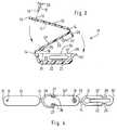
- Fig. 1
- eine Flügelmarke mit integrierter, nach außen abgeschlossener Transponder-Aufnahmeund mit integriertem Verriegelungsstift in Schrägansicht,
- Fig. 2
- eine Flügelmarke mit von außen zugänglicher Transponder-Aufnahme undmit separatem Verriegelungsstift im Längsschnitt,
- Fig. 3
- im Längsschnitt eine z-förmig-dreischenklige Flügelmarke mit separatemVerriegelungsstift als Weiterbildung der Flügelmarke nach Fig. 1 sowie
- Fig. 4
- die Flügelmarke nach Fig. 3 bei gestrecktem Zustand ihrer drei Schenkelin Ansicht gegen die wannenförmige Transponder-Aufnahme, hier aberohne Verriegelungsstift und Transponder gezeigt.
- Fig. 1
- a wing tag with an integrated transponder receptacle that is closed to the outside and with an integrated locking pin in an oblique view,
- Fig. 2
- a wing marker with transponder receptacle accessible from the outside and with a separate locking pin in longitudinal section,
- Fig. 3
- in longitudinal section a z-shaped three-leg wing mark with a separate locking pin as a further development of the wing mark according to FIG. 1 and
- Fig. 4
- 3 with its three legs stretched in view against the trough-shaped transponder receptacle, but here shown without a locking pin and transponder.
Die in Fig. 1 in perspektivischer Darstellung skizzierte, im wesentlichen U-oderV-förmigeFlügelmarke 11 ist einteilig aus steifelastischem Kunststoff gespritzt. Ihrerelativ biegesteifen Schenkel 12 sind im Bereiche des Joch 13 biegeelastisch miteinanderverbunden, wofür die Dicke des Schenkel-Querschnitts hier zu einemBiege- oder Sollbruch-Bereich 14 geschwächt ist. An den stirnseitig gegenüberliegendenfreien Schenkelenden 15 laufen die Schenkel 12 in im wesentlichen kreisförmigangeformte Platten 16 aus. An der einen ist, auf die andere zu weisend, einVerriegelungsstift 17 mit Widerhaken-Spitze 18 angeformt. Diese kann durch einLoch 19 in der ringförmigen gegenüberliegenden Platte 16 hindurchgedrückt, danachaber ohne mechanische Zerstörung nicht wieder daraus zurückgezogen werden.The sketched in a perspective view in FIG. 1, essentially U orV-
Der eine, in der Zeichnung oben dargestellte und bei der Answendung sichtseitigvor dem Flügel gelegene Schenkel 12 kann außen als Informationsträger 20 ausgebildetsein, also etwa mit einem Oberflächen-Finish zum Bekleben oder zum Bedruckenmit einer visuell aufnehmbaren Information ausgestattet sein (die etwaalphanumerisch oder als Barcode darstellbar ist; in der Zeichnung nicht berücksichtigt).Der gegenüberliegende, in der Zeichnung unten dargestellte und bei derAnwendung zwischen Flügel und Körper des Geflügels gelegene Schenkel 12' istals Transponderträger ausgestattet.The one shown in the drawing above and on the visible side when used
Vorzugsweise wird ein Transponder 21 (Fig. 2; in Fig. 1 nicht dargestellt) in derForm eines an sich für Tierkörperinjektion ausgelegten kleinen Glasröhrchens eingesetzt, in dem ein Speicherchip an eine, auf Resonanz bezüglich einer definiertenAbfrage-Hochfrequenz abgestimmte, Subminiatur-Ferritkernspule angeschlossenist. Ein Abfragegeld dieser Frequenz induziert in den Transponder 21 die elektrischeEnergie für das Auslesen des Speichers mit der Folge, daß das Abfragefeld imRhythmus der abgespeicherten Identinformation bedämpft (moduliert) wird. EineDemodulation dieser zeitabhängigen Bedämpfung liefert im Lesegerät, von demdas Hochfrequenz-Afragefeld abgestrahlt wird, eine decodierbare Darstellung derbinärcodierten Identinformation des gerade vom Abfragegeld erfaßten Transponders21 zur Kennung des Tieres, etwa des Kükens, das mit dieser Transponder-Marke11 ausgestattet ist.A transponder 21 (FIG. 2; not shown in FIG. 1) is preferably used in theIn the form of a small glass tube designed for carcass injection,in which a memory chip resonates with a defined oneInterrogated radio frequency tuned, subminiature ferrite core coil connectedis. A query money of this frequency induces the electrical in the
Das Glasröhrchen des Transponders 21 kann unmittelbar auf die innere oder äußereOberfläche eines den Transponder tragenden Schenkels 12' aufgeklebt werden.Einfacher und vor allem zuverlässiger ist die Montage, wenn in dem Transponderschenkel12' eine in dessen Längsrichtung sich erstreckende wannenförmige Aufnahme22 eingeformt ist, die sich auch über die Materialstärke diese Schenkels 12'hinaus nach außen vorwölben kann, wie in Fig. 1 berücksichtigt. In diese wannenförmigeAufnahme 22 kann das Glasröhrchen des Transponders 21 dann problemloseingelegt und darin form- oder kraftschlüssig festgelegt werden. Die kraftschlüssigeFestlegung kann durch einen Kleber erfolgen, oder durch Überschweißenetwa mittels eines Hüllblattes als Abdeckung 23, das auf die Innenseite desTransponderschenkels 12', die wannenförmige Aufnahme 22 überdeckend, angeformtist oder aufgelegt wird. Besonders einfach ist die Handhabung, wenn solchein dünnes längliches Hüllblatt nach Art einer Spritzhaut längsseits oder zungenförmigquerseitig an die Innenseite des Transponderschenkels 12' in der Nachbarschaftder Aufnahme 22 angelenkt (also als Klappe angespritzt) ist und dann nachdem Einlegen des Transponders 21 nur darübergeschwenkt und am freien Endeverklebt oder verschweißt zu werden braucht, wie in Fig. 1 berücksichtigt.The glass tube of the
Insbesondere dann, wenn z.B. nach einem Generationenwechsel eine Wiederverwendungdes Transponders 21 für eine andere Flügelmarke 11 vorgesehen ist,kann es zweckmäßiger sein, das Glasröhrchen lediglich kraftschlüssig in die Aufnahme22 einzusetzen, etwa in die wannenförmige Vertiefung gemäß Fig. 1 einzuklemmen.Zweckmäßig ist für diesen Fall eine taschenförmige Aufnahme 22 nachArt eines Sackloches (Fig. 2), die dann außen am Transponderschenkel 12' längsseitsangeordnet, vorzugsweise angeformt, und zweckmäßigerweise dadurch zugänglich ist, daß sie an einem Stirnende zum Einschieben des Transponderröhrchens21 offen ist. Gegenüberliegen kann diese an sich sacklockförmige Aufnahme22 ebenfalls mit einer kleinen Öffnung 24 ausgestattet sein, um hier einenAusstoßdorn zum Herausschieben des Transponders 21 aus seiner gegenüber geöffnetenAufnahme 22 einführen zu können.Especially when e.g. reuse after a generation changeof the
Bei der zweischenkligen Variante nach Fig. 2 ist der Verriegelungsstift 17 nichtintegraler Bestandteil der Flügelmarke 11, sondern separat ausgebildet. Seine Widerhaken-Spitze18 kann durch gelochte Platten 16 an den Schenkel-Stirnenden 15hindurchgesteckt und gleich dabei, oder mit einer gegenüberliegend hinterlegtenLochscheibe 25, verrastet werden. Einsteckseitig begrenzt ein umlaufender Kragen26 am Stift 17 den Einsteckvorgang in die bei zusammengelegten Schenkeln12-12' fluchtenden Löcher 19.2, the
Zum Anlegen der Flügelmarke 11 etwa mit einer Klemmzange sind die Schenkel12,12' (bei bereits mit Transpondern 21 bestückten Aufnahmen 22) bis annäherndin die gestreckte Form auseinandergeklappt, so daß sie störungsfrei aus einem MagazinStück für Stück nachgeliefert werden können. Das transponderseitige Schenkelende15 wird dem Geflügel hinter dem Flügelknochen durch den abgespreitztenFlügel geschoben, woraufhin die beiden Schenkel 12,12' um das Joch 13 zusammengebogenwerden. Dadurch liegen die Platten 16 koaxial vor dem Flügelknochen,und sie können durch den integral angeformten oder durch den aus dem Magazinmitgelieferten Verriegelungsstift 17 miteinander formschlüssig verbundenwerden, so daß dann bei der angelegten Flügelmarke 11 der Informationsträger 20vor dem Flügel sichtbar ist.For applying the
Um die Flügelmarke 11 wieder zu entfernen, etwa um den Transponder 21 in eineranderen Flügelmarke 11 (bei einem anderen Tier) wiederverwenden zu können,wird der Veirriegelungsstift 17 durchschnitten und/oder der als Sollbruchstelle ausgelegteverjüngte Bereich 14 im Joch 13 aufgebrochen oder ebenfalls aufgeschnitten,so daß sich jedenfalls die beiden nun nicht mehr fest miteinander verbundenenSchenkel 12,12' nach beiden Seiten des Flügels abheben lassen. Der Glasröhrchen-Transponder21 wird aus der wannenförmigen bzw. sacklochförmigen Aufnahme22 in Querrichtung herausgehoben bzw. in Längsrichtung herausgeschoben undkann unmittelbar zur Bestückung einer anderen Flügelmarke 11 dienen: während bei Wiederverwendung einer Flügelmarke 11 insgesamt diese erst desinfiziert werdenmüßte.To remove the
Beim insbesondere gegenüber Fig. 1 abgewandelten Ausführungsbeispiel der Flügelmarke11 nach Fig. 3 / Fig. 4 handelt es sich bei noch offener Marke 11 um dielineare Aufeinanderfolge dreier Schenkel, nämlich eines Abdeck-Schenkels12
jeweilsmittels Film-Scharnieren als den verjüngten Biegebereichen 14 miteinanderverbunden, vorzugsweise einstückig aus leichtem Plastikmaterial gespritzt. DerFlügelknochen des mittels einer solchen Marke 11 nach Fig.3 auszustattenden Geflügelswird zwischen dem Innen-Schenkel 12 und dem an diesen anschließendenAbdeck-Schenkel 12'' eingefaßt und kommt somit nicht mit dem Transponder-Bereichin Berührung. Die Rast-Scheibe 25, welche die Widerhaken-Spitze 18des schlank-konusförmigen Verriegelungsstiftes 17 irrreversibel aufnimmt, ist in derNähe des dem Scharnier-Bereich 14 gegenüberliegenden Endes des Abdeck-Schenkels12
angeordnet bzw. angeformt. Aus der Ansicht in Fig. 4 ist ersichtlich,daß das Loch 19 in der Rastscheibe 25, welche die Widerhaken-Spitze 18 desschlank-konusförmigen Verriegelungsstiftes 17 irreversibel aufnimmt, radial geschlitztist, um das Einführen der Widerhaken-Spitze 18 zu erleichtern und dannzusätzlich zu jenem Formschluß einen Widerhaken-Kraftschluß auf den Schaft desVerriegelungsstiftes 17 auszuüben.In the exemplary embodiment of the
connected to each other by means of film hinges as the
arranged or molded. From the view in Fig. 4 it can be seen that the
Der Röhrchen-Transponder 21 ist wieder in eine wannenförmige Ausbuchtung imTransponder-Schenkel 12', parallel zu dessen Längserstreckung, eingelegt, wobeider Verschluß dieser Aufnahme 22 nun mittels des die beiden äußeren Schenkel12/12' überbrückenden inneren Schenkels 12'' erfolgt. Dafür werden der Transponder-Schenkel12' und der sich an einem Ende anschließende Abdeck-Schenkel12'' um den zum Filmscharnier verjüngten Übergangsbereich 14 in Längsrichtungübereinander geklappt, wodurch die Beschickungsöffnung der wannenförmigenTransponder-Aufnahme 22 mechanisch zuverlässiger als durch eine dünne Zunge(gemäß Fig. 1) abgedeckt wird. Die Anordnung erfährt eine kraftschlüssige, wieder-öffnenbareRast-Verriegelung durch seitliche Klauen 27, die der Rastscheibe25 gegenüber an den Abdeck-Schenkel 12'' seitlich angeformt sind und in örtlichkorrespondierende seitliche Einbuchtungen 28 neben der Aufnahme-Wanne 22 imTransponder-Schenkel 12' eingreifen. Diese Rasthalterung wird stabilisiert durch einen hufeisenförmig zwischen den beiden Klauen 27 längs des benachbarten Stirnendesdes Abdeck-Schenkels 12'' verlaufenden Kragen 29, in den sich das freieSchenkel-Stirnende 15' beim Zusammenklappen dieser beiden Schenkel 12''-12'formschlüssig hineinschmiegt, um dadurch seinem Scharnier-Bereich 14 gegenüberin Längs- und Querrichtung formschlüssig abgestützt zu werden und so die Rastverbindungzu stabilisieren. Um trotz beschränkter Abmessungen in Dickenrichtungdes jeweiligen Schenkels 12 die Federwirkung für die elastisch verformbarenRast-Klauen 27 noch zu verbessern, sind unter deren auf die Längsmittelebene desSchenkels 12'' und damit aufeinander zu weisenden Enden Freisparungen 30 imAbdeck-Schenkel 12'' vorgesehen.The
Dem freien Schenkel-Stirnende 15' gegenüber, also in der Nachbarschaft desscharnierförmigen Übergansbereiches 14 zum mittleren oder Abdeck-Schenkel12'', ist stirnseitig vor der Transponder-Aufnahmewanne 22 im Transponder-Schenkel12' noch eine Aushölung 31 eingeformt, in die bei verschlossener Transponder-Aufnahme22 die unter dem Deck-Schenkel 12'' angeformte Rastscheibe25 eintaucht und die somit auch tief genug für den Eingriff der Verriegelungsstift-Spitze18 ausgelegt ist.Opposite the free leg end 15 ', that is in the vicinity of thehinge-shaped
So ist durch die Weiterbildung von der V-förmigen zweischenkligen Flügelmarke11 zur Z-förmigen dreischenkligen Flügelmarke 11 eine funktionale Trennung zwischendem Befestigungsbereich am Flügelknocken und dem Aufnahmebereich fürden Transponder 21 gewährleistet. Dessen wannenförmige Aufnahme 22 liegt vordem Flügel des mit dieser Marke 11 ausgestatteten Tieres. Die Aufnahme 22 kannohne Lösen der Marke 11 vom Flügel, nach manuellem Aufsprengen des Hufeisen-Rastverschlussesbei den Kragen-Klauen 27, durch bloßes Abklappen desTransponder-Schenkels 12' vom mittleren Schenkel 12'' wieder geöffnet werden,um den Transponder 21 - unter Zurücklassen des Kunststoffteiles (Flügelmarke 11)am Schlachttier - zu anderweitiger Wiederverwendung einfach entnehmen zu können.So is through the training of the V-shaped two-
Mit anderen Worten liegt bei der bevorzugten dreischenkligen Ausführung ein mitdem Transponder-Schenkel 12' reversibel verrastbarer Abdeck-Schenkel 12 beinoch offener Marke 11 in Längsrichtung zwischen dem Transponder-Schenkel12'und einem rückwärtigen Halte- Schenkel (12), welcher seinerseits an seinem freienSchenkelende 15 mittels eines Widerhaken-Stiftes 17 - der Verrastung gegenüber - unter Einfassung eines Flügelknochens mit dem Abdeck-Schenkel 12
formschlüssigverbindbar ist. Diese nach dem Anlegen an den Flügel irreversible Verbindungmuß später, zur Entnahme des Transponders 21 vor dem Schlachten, nicht wiederaufgebrochen werden, weil hierfür dann einfach der Transponder-Schenkel 12' mitseiner längsseits eingeformten Transponder-Aufnahme 22 von der übrigen Flügel-Marke11 und damit vom Flügel des Federvieh abzuklappen ist, um den vergleichsweisekostbaren Transponder 21 bei der nachwachsenden Generation, dannmit neuer Kunststoff-Marke 11, wiederverwenden zu können, während die eigentlichedreischenklige Marke 11 am ausgewachsenen Tier zurückbleibt.In other words, in the preferred three-leg design there is a
with the
is positively connectable. This connection, which is irreversible after being placed on the wing, does not have to be broken again later, in order to remove the
Claims (10)
- Device for providing poultry with a transponder (21),
characterized in that
a slim, rod-shaped transponder (21) is located along oneside (12') made of electrically non-conducting materialof a wing tag (11), which has at least two sides, inparticular is U-, V-, Z- or W-shaped and can be attachedto the poultry by means of two sides (12) which arejoined together in longitudinal direction by way of aflexible region (14) and a locking pin (17) lyingopposite this region (14) and encircle a wing bone, theside (12') being provided in longitudinal direction witha pocket- or trough-shaped seat (22) for the transponder(21), from which the transponder (21) can be taken outagain without the wing tag (11) having to be removedagain. - Device according to Claim 1,
characterized in that
the transponder seat (22) is formed in the shape of apocket on one of the sides (12') and, opposite anentrance at one end, is provided with an opening (24) forthe roughly coaxial operation of an ejector spike for thetransponder (21). - Device according to Claim 1,
characterized in that
the transponder (21) is fixed in a trough-shaped seat(22) which is farmed on one side (12') in longitudinaldirection and can be closed by a cover (23). - Device according to Claim 3,
characterized in that
the cover (23) is formed in the shape of a tongue or flapon the transponder side (12'). - Device according to Claim 3 or 4,
characterized in that,
in the case of a wing tag (11) which has at least threesides, a covering side (12'') is connected to thetransponder side (12') as cover (23) for its seat (22),and in that these two sides (12',12'') can be reversiblylocked together. - Device according to Claim 5,
characterized in that
one of the sides (12'') is surrounded at one end by anarcuate collar (29) which ends in locking claws (27),with which recesses (28) located before the end (15') ofthe side (12') which is adjacent in longitudinal directionare associated. - Device according to one of Claims 3 to 6,
characterized in that
a Z- or W-shaped wing tag (11) made of electrically non-conductingmaterial is provided, the sides (12) of whichare successively joined together in longitudinaldirection by way of flexible regions (14) and, oppositea twin-locking (collar 29), can be joined together by abarbed pin (17). - Device according to Claim 7,
characterized in that
a barbed point (18) is formed on the pin (17) which, fromthe free end (15) of one side, passes through theperforated plate (16) in the connecting region (14) to anadjacent side (12' or 12''). - Device according to one of the preceding claims,
characterized in that
a locking pin (17) with its barbed point (18) passesthrough a slotted plate (16) and engages in a recess(31), which is made in the transponder side (12') infront of one end of the trough-shaped transponderseat (22). - Device according to one of Claims 7 to 9,
characterized in that
a horseshoe-shaped collar (29) is provided, which runsbetween two claws (27) along the adjacent end of acovering side (12''), into which the side's free end(15'), when two successive sides (12'-12'') are foldedtogether, fits snugly and positively so as to bepositively supported in longitudinal and in horizontaldirection opposite the hinged region (14).
Applications Claiming Priority (4)
| Application Number | Priority Date | Filing Date | Title |
|---|---|---|---|
| DE29601041U | 1996-01-23 | ||
| DE29601041UDE29601041U1 (en) | 1996-01-23 | 1996-01-23 | Device for equipping poultry with a transponder |
| DE19644328 | 1996-10-25 | ||
| DE19644328ADE19644328C2 (en) | 1996-01-23 | 1996-10-25 | Device for equipping poultry with a transponder |
Publications (2)
| Publication Number | Publication Date |
|---|---|
| EP0786204A1 EP0786204A1 (en) | 1997-07-30 |
| EP0786204B1true EP0786204B1 (en) | 1998-10-28 |
Family
ID=26030748
Family Applications (1)
| Application Number | Title | Priority Date | Filing Date |
|---|---|---|---|
| EP96119743AExpired - LifetimeEP0786204B1 (en) | 1996-01-23 | 1996-12-10 | Device for fitting birds with a transponder |
Country Status (3)
| Country | Link |
|---|---|
| US (1) | US5891156A (en) |
| EP (1) | EP0786204B1 (en) |
| IL (1) | IL119998A0 (en) |
Families Citing this family (66)
| Publication number | Priority date | Publication date | Assignee | Title |
|---|---|---|---|---|
| AUPO032296A0 (en)* | 1996-06-06 | 1996-07-04 | Finlayson, Dorothy Elizabeth | Ear tag |
| US6494305B1 (en)* | 1998-12-14 | 2002-12-17 | Micron Technology, Inc. | Carcass-tracking apparatus housing carcass-tracking apparatus and carcass-tracking methods |
| ES2177434B1 (en)* | 2000-12-05 | 2004-10-16 | Gesimpex Comercial, S.L. | PROCEDURE AND CAPSULE FOR REMOTE IDENTIFICATION AND MONITORING OF BIRDS. |
| US7232445B2 (en)* | 2000-12-06 | 2007-06-19 | Id, Llc | Apparatus for the endoluminal treatment of gastroesophageal reflux disease (GERD) |
| US8062314B2 (en)* | 2000-12-06 | 2011-11-22 | Ethicon Endo-Surgery, Inc. | Methods for the endoluminal treatment of gastroesophageal reflux disease (GERD) |
| US7727246B2 (en)* | 2000-12-06 | 2010-06-01 | Ethicon Endo-Surgery, Inc. | Methods for endoluminal treatment |
| US20020138086A1 (en)* | 2000-12-06 | 2002-09-26 | Robert Sixto | Surgical clips particularly useful in the endoluminal treatment of gastroesophageal reflux disease (GERD) |
| US6716226B2 (en)* | 2001-06-25 | 2004-04-06 | Inscope Development, Llc | Surgical clip |
| US20020068945A1 (en)* | 2000-12-06 | 2002-06-06 | Robert Sixto | Surgical clips particularly useful in the endoluminal treatment of gastroesophageal reflux disease (GERD) |
| US6808491B2 (en) | 2001-05-21 | 2004-10-26 | Syntheon, Llc | Methods and apparatus for on-endoscope instruments having end effectors and combinations of on-endoscope and through-endoscope instruments |
| US10285694B2 (en) | 2001-10-20 | 2019-05-14 | Covidien Lp | Surgical stapler with timer and feedback display |
| US7464847B2 (en) | 2005-06-03 | 2008-12-16 | Tyco Healthcare Group Lp | Surgical stapler with timer and feedback display |
| GB2392138B (en)* | 2002-08-23 | 2004-10-13 | Shearwell Data Ltd | Animal identifiers |
| US6753779B1 (en)* | 2003-02-11 | 2004-06-22 | B&G Plastics, Inc. | Electronic article surveillance marker assembly |
| CA2609970C (en) | 2005-06-03 | 2014-08-12 | Tyco Healthcare Group Lp | Battery powered surgical instrument |
| US11291443B2 (en) | 2005-06-03 | 2022-04-05 | Covidien Lp | Surgical stapler with timer and feedback display |
| US20070162030A1 (en)* | 2006-01-06 | 2007-07-12 | Ernest Aranyi | Multi-pronged compressive absorbable tack |
| US7431188B1 (en) | 2007-03-15 | 2008-10-07 | Tyco Healthcare Group Lp | Surgical stapling apparatus with powered articulation |
| US7950560B2 (en) | 2007-04-13 | 2011-05-31 | Tyco Healthcare Group Lp | Powered surgical instrument |
| US11259801B2 (en) | 2007-04-13 | 2022-03-01 | Covidien Lp | Powered surgical instrument |
| US8800837B2 (en) | 2007-04-13 | 2014-08-12 | Covidien Lp | Powered surgical instrument |
| US20080255413A1 (en) | 2007-04-13 | 2008-10-16 | Michael Zemlok | Powered surgical instrument |
| ES2330815B1 (en)* | 2007-04-19 | 2010-09-15 | Urbano Herrero Sanchez | ELECTRONIC IDENTIFICATION BRACELET FOR ANIMALS. |
| US7823760B2 (en) | 2007-05-01 | 2010-11-02 | Tyco Healthcare Group Lp | Powered surgical stapling device platform |
| US20080277445A1 (en)* | 2007-05-07 | 2008-11-13 | Zergiebel Earl M | Single fire tacker instrument |
| US7931660B2 (en)* | 2007-05-10 | 2011-04-26 | Tyco Healthcare Group Lp | Powered tacker instrument |
| FR2918841B1 (en)* | 2007-07-19 | 2012-08-10 | Raymond A & Cie | IDENTIFICATION RING FOR ANIMALS |
| US7922063B2 (en) | 2007-10-31 | 2011-04-12 | Tyco Healthcare Group, Lp | Powered surgical instrument |
| US8821514B2 (en) | 2009-06-08 | 2014-09-02 | Covidien Lp | Powered tack applier |
| GB2498666B (en)* | 2010-10-19 | 2015-08-12 | Renewable Energy Systems Americans Inc | Systems and methods for Avian mitigation for wind farms |
| GB2496904A (en)* | 2011-11-28 | 2013-05-29 | Shearwell Data Ltd | Animal identification device |
| JP2013228916A (en)* | 2012-04-26 | 2013-11-07 | Toska Banok Co Ltd | Fastener member and mounting device of fastener member |
| AU2013205528B9 (en)* | 2012-05-17 | 2017-04-06 | Allflex Europe Sas | Animal identification tag |
| CN104603852A (en)* | 2012-05-22 | 2015-05-06 | 关卡系统股份有限公司 | Solid housing tag |
| AU2013224724B2 (en)* | 2012-09-19 | 2017-07-06 | Datamars Sa | Identification tags |
| USD710996S1 (en)* | 2013-12-11 | 2014-08-12 | Fresenius Medical Care Holdings, Inc. | Line separation protector |
| AR100080A1 (en)* | 2014-04-15 | 2016-09-07 | Allflex Europe Sas | BRAND FOR THE IDENTIFICATION OF ANIMALS |
| EP3302306B1 (en) | 2015-05-27 | 2020-07-22 | Coloplast A/S | Grasping tool |
| JP6805650B2 (en)* | 2016-09-01 | 2020-12-23 | 凸版印刷株式会社 | Identification tag |
| US11311295B2 (en) | 2017-05-15 | 2022-04-26 | Covidien Lp | Adaptive powered stapling algorithm with calibration factor |
| US10987104B2 (en) | 2017-10-30 | 2021-04-27 | Covidien Lp | Apparatus for endoscopic procedures |
| US12185949B2 (en) | 2017-10-30 | 2025-01-07 | Covidien Lp | Apparatus for endoscopic procedures |
| US11207066B2 (en) | 2017-10-30 | 2021-12-28 | Covidien Lp | Apparatus for endoscopic procedures |
| US11497490B2 (en) | 2018-07-09 | 2022-11-15 | Covidien Lp | Powered surgical devices including predictive motor control |
| US12137902B2 (en) | 2018-07-25 | 2024-11-12 | Covidien Lp | Adaptive anti-twitch algorithm for powered surgical devices |
| US11197734B2 (en) | 2018-10-30 | 2021-12-14 | Covidien Lp | Load sensing devices for use in surgical instruments |
| US11369372B2 (en) | 2018-11-28 | 2022-06-28 | Covidien Lp | Surgical stapler adapter with flexible cable assembly, flexible fingers, and contact clips |
| GB2580100B (en)* | 2018-12-21 | 2022-03-16 | Agri Tag Ltd | RFID sheep tags |
| US11202635B2 (en) | 2019-02-04 | 2021-12-21 | Covidien Lp | Programmable distal tilt position of end effector for powered surgical devices |
| US11376006B2 (en) | 2019-02-06 | 2022-07-05 | Covidien Lp | End effector force measurement with digital drive circuit |
| US11219461B2 (en) | 2019-03-08 | 2022-01-11 | Covidien Lp | Strain gauge stabilization in a surgical device |
| US11281952B2 (en)* | 2019-06-04 | 2022-03-22 | Trovan, Ltd. | Systems and methods to secure transponders within RFID tags without potting elements |
| US11458244B2 (en) | 2020-02-07 | 2022-10-04 | Covidien Lp | Irrigating surgical apparatus with positive pressure fluid |
| US11553913B2 (en) | 2020-02-11 | 2023-01-17 | Covidien Lp | Electrically-determining tissue cut with surgical stapling apparatus |
| US12029470B2 (en) | 2020-05-21 | 2024-07-09 | Covidien Lp | Simultaneous RF monopolar calibration using a shared return electrode |
| IL275518B (en)* | 2020-06-18 | 2021-10-31 | Scr Eng Ltd | An animal tag |
| US11622768B2 (en) | 2020-07-13 | 2023-04-11 | Covidien Lp | Methods and structure for confirming proper assembly of powered surgical stapling systems |
| US12193884B2 (en) | 2020-11-17 | 2025-01-14 | Covidien Lp | Contactless force measurement of motor torque in powered surgical device |
| US11744580B2 (en) | 2020-11-24 | 2023-09-05 | Covidien Lp | Long stapler reloads with continuous cartridge |
| US11653919B2 (en) | 2020-11-24 | 2023-05-23 | Covidien Lp | Stapler line reinforcement continuity |
| US12016556B2 (en) | 2021-05-03 | 2024-06-25 | Covidien Lp | Handheld electromechanical surgical system |
| US11684362B2 (en) | 2021-06-07 | 2023-06-27 | Covidien Lp | Handheld electromechanical surgical system |
| US11771432B2 (en) | 2021-06-29 | 2023-10-03 | Covidien Lp | Stapling and cutting to default values in the event of strain gauge data integrity loss |
| US12161341B2 (en) | 2021-09-07 | 2024-12-10 | Covidien Lp | Slow speed staple and staple relaxation for stapling optimization |
| CN114158492A (en)* | 2022-01-14 | 2022-03-11 | 青岛贝威智能科技有限公司 | Electronic foot ring manufactured in welding mode |
| US11832823B2 (en) | 2022-02-08 | 2023-12-05 | Covidien Lp | Determination of anvil release during anastomosis |
Family Cites Families (13)
| Publication number | Priority date | Publication date | Assignee | Title |
|---|---|---|---|---|
| US1605868A (en)* | 1925-06-29 | 1926-11-02 | G G Voege | Clasp for bracelets and wrist watches |
| US2970359A (en)* | 1956-09-19 | 1961-02-07 | Horace W Dryden | Locking means for plastic strap |
| US3907182A (en)* | 1973-05-03 | 1975-09-23 | Clyde C Bryant | Receptacle clamp |
| US3955580A (en)* | 1975-03-20 | 1976-05-11 | Roy Dale Thompson | Identification tag and insertion tool for cattle |
| JPS5813190Y2 (en)* | 1979-01-23 | 1983-03-14 | 北川工業株式会社 | flat cable holder |
| DE3441302C1 (en)* | 1984-11-12 | 1986-04-10 | Guido, Jürgen, Dipl.-Ing., 8402 Neutraubling | Pipe clamp made of resilient material |
| US4659000A (en)* | 1986-03-20 | 1987-04-21 | K Mart Corporation | Carrying case for dual instruments |
| DD252532A1 (en)* | 1986-09-09 | 1987-12-23 | Forschungszentrum Fuer Tierpro | BRACKET FOR THE INSTALLATION OF ELECTRONIC ANIMAL DETECTION ELEMENTS |
| US4866213A (en)* | 1988-02-08 | 1989-09-12 | Pawling Corporation | End clip for mesh-clad RFI/EMI shielding strips and shielding strip assembly including same |
| NL9002424A (en)* | 1990-11-08 | 1992-06-01 | Nedap Nv | FIXING RING FOR APPLYING AN OBJECT OR NUMBER TO AN ANIMAL'S LEG (LEG). |
| BE1006747A3 (en)* | 1993-02-26 | 1994-11-29 | Splitthoff Josef | Animal identification equipment |
| IE940321A1 (en)* | 1993-08-11 | 1995-02-22 | Rodney Arthur Stafford | Non-snagging animal ear tags |
| US5461807A (en)* | 1994-04-13 | 1995-10-31 | Fearing Manufacturing Company | Animal eartag electronic transponder |
- 1996
- 1996-12-10EPEP96119743Apatent/EP0786204B1/ennot_activeExpired - Lifetime
- 1997
- 1997-01-13ILIL11999897Apatent/IL119998A0/enunknown
- 1997-01-23USUS08/788,051patent/US5891156A/ennot_activeExpired - Fee Related
Also Published As
| Publication number | Publication date |
|---|---|
| IL119998A0 (en) | 1997-04-15 |
| EP0786204A1 (en) | 1997-07-30 |
| US5891156A (en) | 1999-04-06 |
Similar Documents
| Publication | Publication Date | Title |
|---|---|---|
| EP0786204B1 (en) | Device for fitting birds with a transponder | |
| DE69301707T2 (en) | Anti-fraud electronic identification device | |
| EP1014861B1 (en) | Device for withdrawing biological samples | |
| CA1054794A (en) | Eartags | |
| US20120285056A1 (en) | System and Method for Maintaining Animal Ear Tags | |
| DE69613708T2 (en) | FASTENABLE TRANSPONDER RECEIVER HOUSING | |
| DE29906146U1 (en) | Ear tag for marking an animal | |
| JP2011519556A (en) | Animal tag and manufacturing method thereof | |
| DE69712645T2 (en) | EAR TRAILER | |
| DE19644328C2 (en) | Device for equipping poultry with a transponder | |
| EP0407853B1 (en) | Ear tag for animals | |
| DE19740429A1 (en) | Device for withdrawing biological sample | |
| DE19715473C2 (en) | Electronically identifiable ear tag | |
| EP1234498B1 (en) | Device for marking farm animals with concurrent collection of tissue samples | |
| US5983540A (en) | Method and tagging system for marking and identifying birds | |
| DE69215515T2 (en) | BRAND ARRANGEMENTS | |
| DE60311319T2 (en) | METHOD OF IDENTIFYING AND MONITORING ANIMALS USING ELECTRONIC IDENTIFICATION DEVICES (TRANSPONDER) | |
| DE10139493C1 (en) | Instrument for insertion of animal identification transponder, includes reflexive cutter removing tissue section in sample chamber | |
| DE102006057887A1 (en) | Laser marked leg identification plastic ring for wild or domestic birds | |
| DE29706633U1 (en) | Electronically identifiable ear tag | |
| EP3501270A1 (en) | Method for applying a device containing a transponder | |
| DE69604591T2 (en) | LABELING DEVICE FOR BREEDING ANIMALS SUBJECT TO VETERINARY TREATMENT | |
| DE3929387C1 (en) | ||
| EP0913082A1 (en) | Device for marking animals | |
| DE2515170A1 (en) | LABELS FOR ANIMALS |
Legal Events
| Date | Code | Title | Description |
|---|---|---|---|
| PUAI | Public reference made under article 153(3) epc to a published international application that has entered the european phase | Free format text:ORIGINAL CODE: 0009012 | |
| 17P | Request for examination filed | Effective date:19970527 | |
| AK | Designated contracting states | Kind code of ref document:A1 Designated state(s):DE FR GB NL | |
| 17Q | First examination report despatched | Effective date:19971003 | |
| GRAG | Despatch of communication of intention to grant | Free format text:ORIGINAL CODE: EPIDOS AGRA | |
| GRAG | Despatch of communication of intention to grant | Free format text:ORIGINAL CODE: EPIDOS AGRA | |
| GRAH | Despatch of communication of intention to grant a patent | Free format text:ORIGINAL CODE: EPIDOS IGRA | |
| GRAH | Despatch of communication of intention to grant a patent | Free format text:ORIGINAL CODE: EPIDOS IGRA | |
| GRAA | (expected) grant | Free format text:ORIGINAL CODE: 0009210 | |
| AK | Designated contracting states | Kind code of ref document:B1 Designated state(s):DE FR GB NL | |
| PG25 | Lapsed in a contracting state [announced via postgrant information from national office to epo] | Ref country code:NL Free format text:LAPSE BECAUSE OF FAILURE TO SUBMIT A TRANSLATION OF THE DESCRIPTION OR TO PAY THE FEE WITHIN THE PRESCRIBED TIME-LIMIT Effective date:19981028 | |
| REF | Corresponds to: | Ref document number:59600735 Country of ref document:DE Date of ref document:19981203 | |
| GBT | Gb: translation of ep patent filed (gb section 77(6)(a)/1977) | Effective date:19990201 | |
| ET | Fr: translation filed | ||
| NLV1 | Nl: lapsed or annulled due to failure to fulfill the requirements of art. 29p and 29m of the patents act | ||
| PLBE | No opposition filed within time limit | Free format text:ORIGINAL CODE: 0009261 | |
| STAA | Information on the status of an ep patent application or granted ep patent | Free format text:STATUS: NO OPPOSITION FILED WITHIN TIME LIMIT | |
| RAP2 | Party data changed (patent owner data changed or rights of a patent transferred) | Owner name:EADIE, BRIAN K. M. | |
| RIN2 | Information on inventor provided after grant (corrected) | Free format text:GESSNER, ANNETTE * EADIE, BRIAN K. M. | |
| 26N | No opposition filed | ||
| REG | Reference to a national code | Ref country code:GB Ref legal event code:IF02 | |
| PGFP | Annual fee paid to national office [announced via postgrant information from national office to epo] | Ref country code:GB Payment date:20091215 Year of fee payment:14 Ref country code:FR Payment date:20091203 Year of fee payment:14 | |
| PGFP | Annual fee paid to national office [announced via postgrant information from national office to epo] | Ref country code:DE Payment date:20091217 Year of fee payment:14 | |
| GBPC | Gb: european patent ceased through non-payment of renewal fee | Effective date:20101210 | |
| REG | Reference to a national code | Ref country code:FR Ref legal event code:ST Effective date:20110831 | |
| PG25 | Lapsed in a contracting state [announced via postgrant information from national office to epo] | Ref country code:FR Free format text:LAPSE BECAUSE OF NON-PAYMENT OF DUE FEES Effective date:20110103 | |
| REG | Reference to a national code | Ref country code:DE Ref legal event code:R119 Ref document number:59600735 Country of ref document:DE Effective date:20110701 | |
| PG25 | Lapsed in a contracting state [announced via postgrant information from national office to epo] | Ref country code:GB Free format text:LAPSE BECAUSE OF NON-PAYMENT OF DUE FEES Effective date:20101210 Ref country code:DE Free format text:LAPSE BECAUSE OF NON-PAYMENT OF DUE FEES Effective date:20110701 |