EP0784220B1 - Fiber optic micro cable - Google Patents
Fiber optic micro cableDownload PDFInfo
- Publication number
- EP0784220B1 EP0784220B1EP97400042AEP97400042AEP0784220B1EP 0784220 B1EP0784220 B1EP 0784220B1EP 97400042 AEP97400042 AEP 97400042AEP 97400042 AEP97400042 AEP 97400042AEP 0784220 B1EP0784220 B1EP 0784220B1
- Authority
- EP
- European Patent Office
- Prior art keywords
- cable
- core
- strength members
- jacket
- fiber optic
- Prior art date
- Legal status (The legal status is an assumption and is not a legal conclusion. Google has not performed a legal analysis and makes no representation as to the accuracy of the status listed.)
- Expired - Lifetime
Links
Images

Classifications
- G—PHYSICS
- G02—OPTICS
- G02B—OPTICAL ELEMENTS, SYSTEMS OR APPARATUS
- G02B6/00—Light guides; Structural details of arrangements comprising light guides and other optical elements, e.g. couplings
- G02B6/44—Mechanical structures for providing tensile strength and external protection for fibres, e.g. optical transmission cables
- G02B6/4401—Optical cables
- G02B6/4403—Optical cables with ribbon structure
- G—PHYSICS
- G02—OPTICS
- G02B—OPTICAL ELEMENTS, SYSTEMS OR APPARATUS
- G02B6/00—Light guides; Structural details of arrangements comprising light guides and other optical elements, e.g. couplings
- G02B6/44—Mechanical structures for providing tensile strength and external protection for fibres, e.g. optical transmission cables
- G02B6/4401—Optical cables
- G02B6/4429—Means specially adapted for strengthening or protecting the cables
- G02B6/443—Protective covering
- G02B6/4432—Protective covering with fibre reinforcements
- G02B6/4433—Double reinforcement laying in straight line with optical transmission element
- G—PHYSICS
- G02—OPTICS
- G02B—OPTICAL ELEMENTS, SYSTEMS OR APPARATUS
- G02B6/00—Light guides; Structural details of arrangements comprising light guides and other optical elements, e.g. couplings
- G02B6/44—Mechanical structures for providing tensile strength and external protection for fibres, e.g. optical transmission cables
- G02B6/4401—Optical cables
- G02B6/4429—Means specially adapted for strengthening or protecting the cables
- G02B6/4434—Central member to take up tensile loads
Definitions
- the present inventionrelates to fiber optic communication cables, and more particularly, to fiber optic micro cables.
- optical fibers and fiber optic cables including optical fibersprovide significant advantages over electrical cables, such as coaxial communication cables, because of the vastly increased band width of optical fibers over electrical (metal) conductors and the reduced weight of optical fiber cables as compared to metal cables. For example, it may be desirable to replace a heavy coaxial communication cable with a fiber optic micro cable which has a fraction of the weight of the coaxial cable while providing the above described increased band width.
- a fiber optic micro cablewhich is also referred to as a miniature fiber optic cable, is a cable including one or more optical fibers within a miniature cable structure.
- the miniature cable sizeprovides a light weight, flexible structure which is relatively easy to handle and which takes up a minimum amount of space for storage and installation.
- One known micro cableincludes a plurality of small sized wires nested or stranded around a glass fiber and surrounded by a cable jacket.
- a problem associated with micro cables of this typeis the expense and difficulty associated with stranding the small size wires around an optical fiber.
- the stranding machineryis expensive, and the small wires are difficult to control and subject to breakage during cable manufacture, thereby causing an unreasonable amount of scrap. Additionally, the cable structure fails to provide crush protection to the optical fiber contained therein.
- the bend radius of the cableis limited by the nested or stranded wires.
- the minimum bend radius of the cableis limited by the lay length of the wires around the optical fiber.
- the lay length of the wireshas to be very short, thereby limiting the production rate.
- such a stranded structureoccupies a large amount of the cable's available cross section. This limits the thickness of the cable's protective outer sheath when the maximum overall diameter of the cable is fixed.
- a further problem with such a stranded or nested cable designis that the resulting cable is difficult to splice. The difficulty arises because of the number of strength elements involved which need to be joined. Additionally, the size of the splice would be large and the ability to retain the overall tensile strength of the cable is questionable.
- United States Patent 5,259,055 to Cowen et al.describes a fiber optic micro cable which includes an optical fiber core surrounded by a buffer and a protective sheath.
- the sheathconsists of an ultra violet light curable resin impregnated with fibers to enhance the physical strength characteristics of the micro cable.
- United States Patent 5,440,660 to Dombrowski et ala similar fiber optic micro cable is disclosed which includes the same optical fiber core surrounded by a buffer and a fiber resin re-enforced protective sheath.
- Dombrowski et al.discloses an overcoat made of an ultra violet light curable second resin to improve the handling characteristics of the micro cable by providing a smooth outer surface over the underlying fiber-impregnated resin layer.
- the tensile strength of these cableis limited to the strength of the fibers contained in the fiber impregnated resin that coats the buffered optical fiber core. Additionally, although a buffer material is provided around the optical fiber, there are no other structural members within the cable to absorb crushing compressive forces applied to the cable. Therefore, the optical fiber is not protected from crushing forces applied to the cable.
- Another known micro cableincludes an optical fiber positioned between a pair of strength members, such as steel wires, with a solid extruded jacket of a semi rigid PVC provided around the strength members and fibers.
- the extruded jacketprovides protection from mechanical elements such as abrasion, cut through and kinking.
- this cable designdoes not provide sufficient crush protection to an optical fiber contained within the cable.
- the rigid jacket materialdirectly transmits external forces to the optical fibers contained in the cable, and therefore, when crushing forces are applied to such a cable, damage may result to the optical fibers contained therein.
- German patent application DE 31 31 424discloses a fiber optic cable comprising a core in the form of a separate chamber, including two longitudinally extending strength members constituting the lateral edges or sidewalls of the chamber, at least one optical fiber disposed with an excess length in the chamber between the strength members, and a jacket surrounding the chamber.
- the chamberis made of a pair of longitudinally extending covering sheets made of a plastic material or a metal.
- the chamberis filled with a filling material which is sufficiently soft, such that an optical fiber disposed in the chamber can move in directions transverse to the longitudinal axis of the chamber.
- Each optical fiber in the chambersis arranged in an undulating lay or a flat helical lay, to provide the excess length of the optical fibers.
- Objects of the inventioninclude the provision of an improved fiber optic micro cable which is easy to manufacture and which provides maximum protection for optical fibers in environments where cable size is to be minimized.
- Another object of the present inventionis to provide such an improved fiber optic micro cable which protects the optical fibers contained therein from crushing forces.
- a still further object of the present inventionis to provide such a fiber optic micro cable having improved bend radius, resistance to abrasion, and which may be efficiently stored on a round spool structure
- the present inventionprovides a fiber optic micro cable comprising a core, including two longitudinally extending strength members constituting the lateral edges of the core, at least one optical fiber disposed in the core between the strength members, and a jacket surrounding the core, wherein all void spaces within the jacket are completely filled by the core including the or each optical fiber and the strength members, the jacket being in direct contact with the strength members constituting the lateral edges of the core, and having a variable thickness such that the jacket is thicker in jacket areas adjacent to the strength members at the lateral edges of the core than in jacket areas adjacent to the or each optical fiber, characterized in that the interstice between the strength members constituting the lateral edges of the core is filled with a buffer material being different from the material of the jacket, wherein the or each optical fiber is disposed in a straight lay and is embedded in the buffer material in the interstice between the strength members, the strength members and the or each optical fiber extend longitudinally in a common plane, wherein the buffer material is in direct contact with the strength members and with the jacket in
- multiple fiberscan be positioned between each pair of strength members within the buffer material.
- one optical fibermay be positioned between two strength members.
- one or more optical fibersmay be positioned between a plurality of strength members.
- the buffer materialis selected to provide good adhesion with the jacket and to have a low modules of elasticity to distribute external forces applied to the cable.
- the external forcescould be caused by any combination of mechanical, thermal or pressure influence.
- the external forcesare distributed to the strength members to thereby minimize pressure applied to the optical fibers contained within the cable.
- the jacket materialis selected to be a tough and abrasion resistant material to further protect the cable core.
- the strength membersprovide tensile strength to the cable and have a larger outside diameter than the optical fibers to thereby absorb any crushing forces on the cable.
- a fiber optic micro cable manufactured in accordance with the present inventionprovides a significant improvement over the prior art.
- Using the straight lay design of the inventione.g., the parallel structure of the strength members and optical fibers, provides a cable structure which may be easily manufactured.
- the strength membersprovide the cable with the desired tensile strength.
- the larger diameter of the strength members with respect to the optical fibershelps protect the optical fibers contained within the cable against damage in response to crushing forces.
- Providing the cable jacket with additional jacket material, to thereby form protrusions in the area of the strength membershelps to concentrate crushing forces on to the strength members. This design further minimizes crushing forces transmitted to the optical fibers contained within the cable.
- the low modulus of elasticity buffer material contained within the cablealso helps absorb lateral compressive forces applied to the cable to thereby evenly distribute such forces throughout the cable and minimize compressive forces applied directly to the optical fibers contained therein.
- the straight lay design of the cablesimplifies the joining and splicing procedure such that the original strength and dimension of the cable can be preserved.
- the cable design of the inventionallows a smaller bend radius than prior art micro cables, thereby allowing the use of cable bobbins (spools) with much smaller belly diameters, i.e., the central cylindrical surface of the bobbin may be much smaller. This features enables the user to achieve higher winding efficiency for a given size bobbin.
- a fiber optic micro cable 10 in accordance with the present inventionincludes a core 12 covered by a jacket 14.
- the core 12is a buffered core which includes a pair of longitudinally extending strength members 17 (structural wires) on either side of an optical fiber 20.
- the strength members 17 and the optical fiber 20are embedded in a buffer material 24.
- the strength members 17 and the optical fiber 20are positioned in a common plane, thereby resulting in a generally flat or rectangular shaped cable structure.
- the strength members 17are selected to provide tensile strength to the micro cable 10 and also provide crush protection to the optical fiber 20 contained within the cable 10.
- the strength members 17may be manufactured of a solid metal wire, such as a steel wire or copper wire, or alternatively, the strength members may be stranded metal wires. Additionally, the strength members may be manufactured of high strength non-conductive materials such as fiberglass, reinforced plastic or other high strength dielectric materials.
- the optical fiber 20may be of any suitable type known in the art including a central fiber coated by one or more layers of coating material. The optical fiber may be a single mode, multi-mode, dispersion shifted, etc. optical fiber, depending on the desired application of the optical fiber.
- the central fibermay be coated with one or more layers of coating material to thereby provide the desired mechanical characteristics of the optical fiber.
- the fibermay be coated with one or more layers of UV curable coating material to thereby preserve the structural strength and improve the handling qualities of the optical fiber.
- Hermetically coated fibersmay be used if hydrogen protection is required.
- the buffer material 24is a low modulus of elasticity material which provides the desired compression qualities to thereby distribute compressive forces within the micro cable 10 and minimize forces applied to the optical fiber 20.
- the buffer materialmay be a UV curable buffer material such as CABLELITE manufactured by DSM Desotech.
- the buffer materialmay be a thermoplastic polymer such as HYTREL manufactured by DuPont. It will be understood by those skilled in the art that a variety of buffer materials may be used with the fiber optic micro cable of the present invention, provided that the buffer material provides the desired qualities of having a low modulus of elasticity, and the buffer material provides good adhesion with the jacket material.
- the jacket material 14is selected to be tough and abrasion resistant.
- the jacket 14may be formed from high density polyethylene (HDPE).
- HDPEhigh density polyethylene
- other materialssuch as thermoplastic polymer, e.g., SURLYN manufactured by DuPont, or a UV curable coating, e.g., CABLELITE manufactured by DSM Desotech, may be used as the cable jacket with the cable of the invention.
- thermoplastic polymere.g., SURLYN manufactured by DuPont
- a UV curable coatinge.g., CABLELITE manufactured by DSM Desotech
- the jacket 14is fabricated so that there is slightly more material in the region of the strength members such that the profile of the completed cable includes protrusions 26 (Figs. 1 and 4) in the cable jacket 14 in the area of the strength members 17.
- the extra jacket material in the region of the strength memberhelps to concentrate the crushing forces applied to the cable 10 directly to the strength members 17 and thus relieve some of the stress on the optical fibers 17 contained within the cable 10. This feature thereby increases the ability of the cable to withstand crushing forces applied to the exterior of the cable.
- the strength members 17are sized to give the cable its required tensile strength. Additionally, the strength members 17 are selected to have a slightly larger diameter than the optical fibers so that crushing forces are first applied to the strength members 17 rather than the optical fibers to protect the optical fiber in the crush mode. For example the nominal diameter of the strength members 17 is approximately 0.40 mm while the nominal diameter of the coated optical fiber is approximately 0.25 mm. The overall dimensions of the cable 10 illustrated in Fig. 1 including a pair of strength members 17 and a single optical fiber 20 within the core 24 is approximately 1mm by 1.5mm.
- the micro cable of the present inventionprovides protection to an optical fiber contained therein in two different modes of crushing forces.
- the larger diameter of the strength members 17causes the strength members 17, as opposed to the optical fiber 20, to absorb the crush forces applied to the cable 10.
- the increased thickness of jacketing material 26 in the area of the strength members 17further helps concentrate the crushing forces on to the strength members. Any crushing forces that are applied to the core 12 are equally distributed throughout the core 12 by the low modulus of elasticity buffer material 24 such that local concentrations of crushing forces do not damage the optical fiber 20.
- the present inventionprovides a second mode of crush protection in the lateral direction. If crushing forces are applied to the short or round edges 30 of the cable 10, the cushioning effect of the buffer material 24 helps distribute these crushing forces throughout the core 12.
- An added advantage of the present inventionis that the flat construction of the micro cable causes the cable to have a natural tendency to conform to the flat dimension of the cable when the cable is bent around obstacles. Therefore, the cable is naturally exposed to the stronger mode of crush protection by exposing the flat surface 27 of the cable to external crushing forces.
- the flat cable designalso lends itself to easy storage of the cable on a spool because the naturally flat design of the invention packs more effectively than a round structure.
- the cable design of the inventionallows a smaller bend radius than prior art micro cables, thereby allowing the use of cable bobbins (spools) with much smaller belly diameters. This features enables the user to achieve higher winding efficiency for a given size bobbin.
- the inventiondoes not use stranded or nested wires around a central optical fiber, problems associated with limited bend radius of the cable are eliminated. Additionally, the straight lay of the invention simplifies splicing of the cable. The strength member 17 and fibers 20 can be easily spliced and the jacket 14 restored with a diameter close to the original un-spliced cable. Additionally, the tensile strength of the spliced cable will be near that of the original un-spliced cable.
- a second embodiment of the invention 10aincludes a plurality of parallel running strength members 17a. Between each of the strength members 17a is positioned a single optical fiber 20a. As with the embodiment of Fig. 1, the strength members 17a and optical fibers 20a are embedded within a core 12a of buffer material 24a. The core 12a is coated with a protective jacket 14a (outer sheath).
- the jacket materialis of an increased thickness 26a at least in the area of the end strength members, i.e., the strength members on the outside edges of the cable 10a.
- the jacket material 14may be of an increased thickness 26a in all of the areas of the strength member 17a, as illustrated in Fig. 2, to thereby provide superior crush protection throughout the width of the cable 10a so that optical fibers 20a are not damaged when the cable is exposed to compressive or crushing forces.
- a third embodiment of the inventionincludes a plurality of optical fibers 20b positioned between a pair of strength members 17b.
- the number of optical fibers 20b positioned between the strength members 17bis selected to provide the superior crush protection qualities to the cable while also maximizing the optical fiber content within the cable.
- the strength members 17b and optical fibers 20bare included in a core 12b of buffer material 24b, and the core 12b is surrounded by a protective jacket 14b. Excess jacket material 26b is provided in the area of the strength member 17b. Additional strength member 17b may be positioned within the cable as necessary to preserve the superior crush resistant characteristics of the cable.
- optical fiber and strength membersmay be provided in a fiber optic micro cable manufactured in accordance with the invention.
- a cablemay be provided having a plurality of optical fibers between pairs of strength members.
- two or more strength membersmay be provided on at least one side of each optical fiber.
- a plurality of strength membersmay be provided on at least one side of a plurality of optical fibers.
- the strength member 17, 17a, 17bmay be an electronic signal transmission media, such as copper wires, for carrying electrical current to power devices, such as optical repeaters.
- the copper wiremay be used to transmit electronic data and signaling.
- the buffer material 24, 24a, 24b and the jacket material 14, 14a, 14bis selected to provide proper insulation for the copper wires.
Landscapes
- Physics & Mathematics (AREA)
- General Physics & Mathematics (AREA)
- Optics & Photonics (AREA)
- Communication Cables (AREA)
- Light Guides In General And Applications Therefor (AREA)
Description
- The present invention relates to fiber optic communication cables, and more particularly, to fiber optic micro cables.
- It is well known that optical fibers and fiber optic cables including optical fibers provide significant advantages over electrical cables, such as coaxial communication cables, because of the vastly increased band width of optical fibers over electrical (metal) conductors and the reduced weight of optical fiber cables as compared to metal cables. For example, it may be desirable to replace a heavy coaxial communication cable with a fiber optic micro cable which has a fraction of the weight of the coaxial cable while providing the above described increased band width.
- As is known in the art, a fiber optic micro cable, which is also referred to as a miniature fiber optic cable, is a cable including one or more optical fibers within a miniature cable structure. The miniature cable size provides a light weight, flexible structure which is relatively easy to handle and which takes up a minimum amount of space for storage and installation.
- One known micro cable includes a plurality of small sized wires nested or stranded around a glass fiber and surrounded by a cable jacket. A problem associated with micro cables of this type is the expense and difficulty associated with stranding the small size wires around an optical fiber. The stranding machinery is expensive, and the small wires are difficult to control and subject to breakage during cable manufacture, thereby causing an unreasonable amount of scrap. Additionally, the cable structure fails to provide crush protection to the optical fiber contained therein.
- Another problem associated with such optical fiber cables is the bend radius of the cable is limited by the nested or stranded wires. In particular, the minimum bend radius of the cable is limited by the lay length of the wires around the optical fiber. In order to manufacture such a stranded cable with improved bend protection, the lay length of the wires has to be very short, thereby limiting the production rate. Additionally, such a stranded structure occupies a large amount of the cable's available cross section. This limits the thickness of the cable's protective outer sheath when the maximum overall diameter of the cable is fixed.
- A further problem with such a stranded or nested cable design is that the resulting cable is difficult to splice. The difficulty arises because of the number of strength elements involved which need to be joined. Additionally, the size of the splice would be large and the ability to retain the overall tensile strength of the cable is questionable.
- United States Patent 5,259,055 to Cowen et al. describes a fiber optic micro cable which includes an optical fiber core surrounded by a buffer and a protective sheath. The sheath consists of an ultra violet light curable resin impregnated with fibers to enhance the physical strength characteristics of the micro cable. In United States Patent 5,440,660 to Dombrowski et al, a similar fiber optic micro cable is disclosed which includes the same optical fiber core surrounded by a buffer and a fiber resin re-enforced protective sheath. Additionally, Dombrowski et al. discloses an overcoat made of an ultra violet light curable second resin to improve the handling characteristics of the micro cable by providing a smooth outer surface over the underlying fiber-impregnated resin layer. The tensile strength of these cable is limited to the strength of the fibers contained in the fiber impregnated resin that coats the buffered optical fiber core. Additionally, although a buffer material is provided around the optical fiber, there are no other structural members within the cable to absorb crushing compressive forces applied to the cable. Therefore, the optical fiber is not protected from crushing forces applied to the cable.
- Another known micro cable includes an optical fiber positioned between a pair of strength members, such as steel wires, with a solid extruded jacket of a semi rigid PVC provided around the strength members and fibers. The extruded jacket provides protection from mechanical elements such as abrasion, cut through and kinking. However, this cable design does not provide sufficient crush protection to an optical fiber contained within the cable. The rigid jacket material directly transmits external forces to the optical fibers contained in the cable, and therefore, when crushing forces are applied to such a cable, damage may result to the optical fibers contained therein.
- German patent application DE 31 31 424 discloses a fiber optic cable comprising a core in the form of a separate chamber, including two longitudinally extending strength members constituting the lateral edges or sidewalls of the chamber, at least one optical fiber disposed with an excess length in the chamber between the strength members, and a jacket surrounding the chamber. The chamber is made of a pair of longitudinally extending covering sheets made of a plastic material or a metal. The chamber is filled with a filling material which is sufficiently soft, such that an optical fiber disposed in the chamber can move in directions transverse to the longitudinal axis of the chamber. Each optical fiber in the chambers is arranged in an undulating lay or a flat helical lay, to provide the excess length of the optical fibers.
- Therefore, a need exists for a fiber optic micro cable which is easy to manufacture, provides adequate crush protection, provides a cable bend radius close to the fiber limit, and which is easy to splice.
- Objects of the invention include the provision of an improved fiber optic micro cable which is easy to manufacture and which provides maximum protection for optical fibers in environments where cable size is to be minimized.
- Another object of the present invention is to provide such an improved fiber optic micro cable which protects the optical fibers contained therein from crushing forces.
- A still further object of the present invention is to provide such a fiber optic micro cable having improved bend radius, resistance to abrasion, and which may be efficiently stored on a round spool structure
- To this end, the present invention provides a fiber optic micro cable comprising a core, including two longitudinally extending strength members constituting the lateral edges of the core, at least one optical fiber disposed in the core between the strength members, and a jacket surrounding the core, wherein all void spaces within the jacket are completely filled by the core including the or each optical fiber and the strength members, the jacket being in direct contact with the strength members constituting the lateral edges of the core, and having a variable thickness such that the jacket is thicker in jacket areas adjacent to the strength members at the lateral edges of the core than in jacket areas adjacent to the or each optical fiber, characterized in that the interstice between the strength members constituting the lateral edges of the core is filled with a buffer material being different from the material of the jacket, wherein the or each optical fiber is disposed in a straight lay and is embedded in the buffer material in the interstice between the strength members, the strength members and the or each optical fiber extend longitudinally in a common plane, wherein the buffer material is in direct contact with the strength members and with the jacket in at least the jacket areas adjacent to the or each optical fiber..
- In accordance with one aspect of the present invention, multiple fibers can be positioned between each pair of strength members within the buffer material.
- In accordance with another aspect of the present invention, one optical fiber may be positioned between two strength members.
- In accordance with a further aspect of the invention, one or more optical fibers may be positioned between a plurality of strength members.
- In further accord with the present invention, the buffer material is selected to provide good adhesion with the jacket and to have a low modules of elasticity to distribute external forces applied to the cable. The external forces could be caused by any combination of mechanical, thermal or pressure influence. The external forces are distributed to the strength members to thereby minimize pressure applied to the optical fibers contained within the cable. The jacket material is selected to be a tough and abrasion resistant material to further protect the cable core.
- According further to the present invention, the jacket is fabricated so that there is slightly more jacket material in the area of the strength members to thereby provide an external profile of the jacket with protrusions in the areas of the strength members. Therefore, when external compressive forces are applied to the cable, the forces are concentrated to first be reacted by the strength members rather than the optical fibers.
- In still further accord with the present invention, the strength members provide tensile strength to the cable and have a larger outside diameter than the optical fibers to thereby absorb any crushing forces on the cable.
- A fiber optic micro cable manufactured in accordance with the present invention provides a significant improvement over the prior art. Using the straight lay design of the invention, e.g., the parallel structure of the strength members and optical fibers, provides a cable structure which may be easily manufactured. Additionally, the strength members provide the cable with the desired tensile strength. The larger diameter of the strength members with respect to the optical fibers helps protect the optical fibers contained within the cable against damage in response to crushing forces. Providing the cable jacket with additional jacket material, to thereby form protrusions in the area of the strength members, helps to concentrate crushing forces on to the strength members. This design further minimizes crushing forces transmitted to the optical fibers contained within the cable. The low modulus of elasticity buffer material contained within the cable also helps absorb lateral compressive forces applied to the cable to thereby evenly distribute such forces throughout the cable and minimize compressive forces applied directly to the optical fibers contained therein. The straight lay design of the cable simplifies the joining and splicing procedure such that the original strength and dimension of the cable can be preserved. The cable design of the invention allows a smaller bend radius than prior art micro cables, thereby allowing the use of cable bobbins (spools) with much smaller belly diameters, i.e., the central cylindrical surface of the bobbin may be much smaller. This features enables the user to achieve higher winding efficiency for a given size bobbin.
- The foregoing and other objects, features and advantages of the present invention will become more apparent in light of the following detailed description of exemplary embodiments thereof, as illustrated in the accompanying drawings.
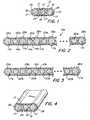
- Fig. 1 is a cross-sectional view of a fiber optic micro cable manufactured in accordance with the present invention;
- Fig. 2 is a cross-sectional view of a second embodiment of the fiber optic micro cable of Fig. 1.;
- Fig. 3 is a cross-sectional view of a third embodiment of the fiber optic micro cable of the invention; and
- Fig. 4 is a perspective cross-sectional view of the fiber optic micro cable of Fig. 1.
- Referring to Fig. 1, a fiber
optic micro cable 10 in accordance with the present invention includes a core 12 covered by ajacket 14. Thecore 12 is a buffered core which includes a pair of longitudinally extending strength members 17 (structural wires) on either side of anoptical fiber 20. Thestrength members 17 and theoptical fiber 20 are embedded in abuffer material 24. Thestrength members 17 and theoptical fiber 20 are positioned in a common plane, thereby resulting in a generally flat or rectangular shaped cable structure. - The
strength members 17 are selected to provide tensile strength to themicro cable 10 and also provide crush protection to theoptical fiber 20 contained within thecable 10. Thestrength members 17 may be manufactured of a solid metal wire, such as a steel wire or copper wire, or alternatively, the strength members may be stranded metal wires. Additionally, the strength members may be manufactured of high strength non-conductive materials such as fiberglass, reinforced plastic or other high strength dielectric materials. Theoptical fiber 20 may be of any suitable type known in the art including a central fiber coated by one or more layers of coating material. The optical fiber may be a single mode, multi-mode, dispersion shifted, etc. optical fiber, depending on the desired application of the optical fiber. As is known in the art, the central fiber may be coated with one or more layers of coating material to thereby provide the desired mechanical characteristics of the optical fiber. For example, the fiber may be coated with one or more layers of UV curable coating material to thereby preserve the structural strength and improve the handling qualities of the optical fiber. Hermetically coated fibers may be used if hydrogen protection is required. - The
buffer material 24 is a low modulus of elasticity material which provides the desired compression qualities to thereby distribute compressive forces within themicro cable 10 and minimize forces applied to theoptical fiber 20. For example, the buffer material may be a UV curable buffer material such as CABLELITE manufactured by DSM Desotech. Alternatively, the buffer material may be a thermoplastic polymer such as HYTREL manufactured by DuPont. It will be understood by those skilled in the art that a variety of buffer materials may be used with the fiber optic micro cable of the present invention, provided that the buffer material provides the desired qualities of having a low modulus of elasticity, and the buffer material provides good adhesion with the jacket material. - Surrounding the
cable core 12 is an outer sheath orjacket 14. Thejacket material 14 is selected to be tough and abrasion resistant. For example, thejacket 14 may be formed from high density polyethylene (HDPE). Alternatively, other materials such as thermoplastic polymer, e.g., SURLYN manufactured by DuPont, or a UV curable coating, e.g., CABLELITE manufactured by DSM Desotech, may be used as the cable jacket with the cable of the invention. It will also be understood by those skilled in the art that a variety of jacket materials may be used with the fiber optic micro cable of the present invention, provided that the jacket material provides the desired qualities of abrasion resistance and adhesion with the buffer material. - The
jacket 14 is fabricated so that there is slightly more material in the region of the strength members such that the profile of the completed cable includes protrusions 26 (Figs. 1 and 4) in thecable jacket 14 in the area of thestrength members 17. The extra jacket material in the region of the strength member helps to concentrate the crushing forces applied to thecable 10 directly to thestrength members 17 and thus relieve some of the stress on theoptical fibers 17 contained within thecable 10. This feature thereby increases the ability of the cable to withstand crushing forces applied to the exterior of the cable. - The
strength members 17 are sized to give the cable its required tensile strength. Additionally, thestrength members 17 are selected to have a slightly larger diameter than the optical fibers so that crushing forces are first applied to thestrength members 17 rather than the optical fibers to protect the optical fiber in the crush mode. For example the nominal diameter of thestrength members 17 is approximately 0.40 mm while the nominal diameter of the coated optical fiber is approximately 0.25 mm. The overall dimensions of thecable 10 illustrated in Fig. 1 including a pair ofstrength members 17 and a singleoptical fiber 20 within thecore 24 is approximately 1mm by 1.5mm. - The micro cable of the present invention provides protection to an optical fiber contained therein in two different modes of crushing forces. First, as described above, when crushing forces are applied to the longer or
flat planes 27 of thecable 10, the larger diameter of thestrength members 17 causes thestrength members 17, as opposed to theoptical fiber 20, to absorb the crush forces applied to thecable 10. Additionally, the increased thickness of jacketingmaterial 26 in the area of thestrength members 17 further helps concentrate the crushing forces on to the strength members. Any crushing forces that are applied to the core 12 are equally distributed throughout the core 12 by the low modulus ofelasticity buffer material 24 such that local concentrations of crushing forces do not damage theoptical fiber 20. - The present invention provides a second mode of crush protection in the lateral direction. If crushing forces are applied to the short or
round edges 30 of thecable 10, the cushioning effect of thebuffer material 24 helps distribute these crushing forces throughout thecore 12. - An added advantage of the present invention is that the flat construction of the micro cable causes the cable to have a natural tendency to conform to the flat dimension of the cable when the cable is bent around obstacles. Therefore, the cable is naturally exposed to the stronger mode of crush protection by exposing the
flat surface 27 of the cable to external crushing forces. The flat cable design also lends itself to easy storage of the cable on a spool because the naturally flat design of the invention packs more effectively than a round structure. The cable design of the invention allows a smaller bend radius than prior art micro cables, thereby allowing the use of cable bobbins (spools) with much smaller belly diameters. This features enables the user to achieve higher winding efficiency for a given size bobbin. Because the invention does not use stranded or nested wires around a central optical fiber, problems associated with limited bend radius of the cable are eliminated. Additionally, the straight lay of the invention simplifies splicing of the cable. Thestrength member 17 andfibers 20 can be easily spliced and thejacket 14 restored with a diameter close to the original un-spliced cable. Additionally, the tensile strength of the spliced cable will be near that of the original un-spliced cable. - The invention has been described thus far as containing a single
optical fiber 20 positioned between a pair ofstrength members 17 within acore 12 of themicro cable 10. However, the cable of the invention may be provided with a plurality of optical fibers and strength members within the core of the cable. Referring to Fig. 2, a second embodiment of theinvention 10a includes a plurality of parallel running strength members 17a. Between each of the strength members 17a is positioned a singleoptical fiber 20a. As with the embodiment of Fig. 1, the strength members 17a andoptical fibers 20a are embedded within acore 12a of buffer material 24a. Thecore 12a is coated with a protective jacket 14a (outer sheath). The jacket material is of an increasedthickness 26a at least in the area of the end strength members, i.e., the strength members on the outside edges of thecable 10a. However, thejacket material 14 may be of an increasedthickness 26a in all of the areas of the strength member 17a, as illustrated in Fig. 2, to thereby provide superior crush protection throughout the width of thecable 10a so thatoptical fibers 20a are not damaged when the cable is exposed to compressive or crushing forces. - Referring now to Fig. 3, a third embodiment of the invention includes a plurality of
optical fibers 20b positioned between a pair of strength members 17b. In this application, the number ofoptical fibers 20b positioned between the strength members 17b is selected to provide the superior crush protection qualities to the cable while also maximizing the optical fiber content within the cable. As with the other embodiments, the strength members 17b andoptical fibers 20b are included in a core 12b of buffer material 24b, and the core 12b is surrounded by a protective jacket 14b.Excess jacket material 26b is provided in the area of the strength member 17b. Additional strength member 17b may be positioned within the cable as necessary to preserve the superior crush resistant characteristics of the cable. - As will be understood by those skilled in the art, various combination of optical fiber and strength members may be provided in a fiber optic micro cable manufactured in accordance with the invention. For example, as illustrated in Fig. 5, a cable may be provided having a plurality of optical fibers between pairs of strength members. Similarly, as illustrated in Fig. 6, two or more strength members may be provided on at least one side of each optical fiber. Additionally, as illustrated in Fig. 7, a plurality of strength members may be provided on at least one side of a plurality of optical fibers.
- If the desired, the
strength member 17, 17a, 17b (Figs. 1-3) may be an electronic signal transmission media, such as copper wires, for carrying electrical current to power devices, such as optical repeaters. Alternatively, the copper wire may be used to transmit electronic data and signaling. In this case, thebuffer material 24, 24a, 24b and thejacket material 14, 14a, 14b is selected to provide proper insulation for the copper wires.
Claims (14)
- A fiber optic micro cable (10; 10b) comprising a core (12; 12b), including two longitudinally extending strength members (17; 17b) constituting the lateral edges of said core (12; 12b), at least one optical fiber (20; 20b) disposed in said core (12; 12b) between said strength members (17; 17b), and a jacket (14; 14b) surrounding said core (12; 12b), wherein all void spaces within said jacket (14; 14b) are completely filled by said core (12; 12b) including the or each optical fiber (20; 20b) and said strength members (17; 17b), said jacket (14; 14b) being in direct contact with said strength members (17; 17b) constituting said lateral edges of said core (12; 12b), and having a variable thickness such that said jacket (14; 14b) is thicker in jacket areas (26; 26b) adjacent to said strength members (17; 17b) at said lateral edges of said core (12; 12b) than in jacket areas adjacent to the or each optical fiber (20; 20b),characterized in that the interstice between said strength members (17; 17b) constituting said lateral edges of said core (12; 12b) is filled with a buffer material (24; 24b) being different from said material of said jacket (14; 14b), wherein the or each optical fiber (20; 20b) is disposed in a straight lay and is embedded in said buffer material (24; 24b) in said interstice between said strength members (17; 17b), said strength members (17; 17b) and the or each optical fiber (20; 20b) extend longitudinally in a common plane, wherein said buffer material (24; 24b) is in direct contact with said strength members (17; 17b) and with said jacket (14; 14b) in at least said jacket areas adjacent to the or each optical fiber (20; 20b).
- A fiber optic micro cable (10a) according to claim 1, wherein said core (12a) includes at least one longitudinally extending further strength member (17a) embedded in said buffer material (24a) and positioned between said strength members (17a) constituting the lateral edges of said core (12a).
- A fiber optic micro cable (10a) according to claim 2, wherein said jacket (14a) has a variable thickness such that said jacket (14a) is thicker in jacket areas adjacent to the or each further strength member (17a) embedded in said buffer material (24a) than in said jacket areas adjacent to the or each optical fiber (20a).
- A fiber optic micro cable (10a) according to claim 2 or 3, wherein the or each further strength member (17a) embedded in said buffer material (24a) is positioned in said core (12a) such that only one optical fiber (20a) is positioned between a strength member (17a) constituting a lateral edge of said core (12a) and a further strength member (17a) or between two further strength members (17a).
- A fiber optic micro cable (10a) according to claim 2 or 3, wherein the or each further strength member (17a) embedded in said buffer material (24a) is positioned in said core (12a) such that a plurality of optical fibers (20a) is positioned between a strength member (17a) constituting a lateral edge of said core (12a) and a further strength member (17a) or between two further strength members (17a).
- A fiber optic micro cable (10; 10a; 10b) according to claim 2, 3 or 4, wherein said strength members (17; 17a; 17b) and the or each further strength member (17a) embedded in said buffer material (24; 24a; 24b) are positioned in said core (12; 12a; 12b) such that a strength member (17; 17a; 17b) constituting a lateral edge of said core (12; 12a; 12b) and at least one further strength member (17a) or at least two further strength members (17a) are positioned on at least one side of an optical fiber (20; 20a; 20b).
- A fiber optic micro cable (10; 10a; 10b) according to claim 2, 3 or 5, wherein said strength members (17; 17a; 17b) and the or each further strength members (17a) embedded in said buffer material (24; 24a; 24b) are positioned in said core (12; 12a; 12b) such that a strength member (17; 17a; 17b) constituting a lateral edge of said core (12; 12a; 12b) and at least one further strength member (17a) or at least two further strength members (17a) are positioned on at least one side of a plurality of optical fibers (20; 20a; 20b).
- A fiber optic micro cable (10; 10a; 10b) according to any of the previous claims, wherein said buffer material (24; 24a; 24b) provides adhesion with said material of said jacket (14; 14a; 14b).
- A fiber optic micro cable (10; 10a; 10b) according to any of the previous claims, wherein said material of said jacket (14; 14a; 14b) is abrasion resistant and provides adhesion with said buffer material (24; 24a; 24b).
- A fiber optic micro cable (10; 10a; 10b) according to any of the previous claims, wherein the diameter of said strength members (17; 17a; 17b) and the or each further strength member (17a) is larger than the diameter of the or each optical fiber (20; 20a; 20b).
- A fiber optic micro cable (10; 10a; 10b) according to any of the previous claims, wherein said strength members (17; 17a; 17b) or the or each further strength member (17a) are electronic signal transmission media, and wherein said buffer material (24; 24a; 24b) and said material of said jacket (14; 14a; 14b) have been selected to provide electrical insulation to said strength members (17; 17a; 17b) and the or each further strength member (17a).
- A fiber optic micro cable (10; 10a; 10b) according to any of the claims 1 - 10, wherein said strength members (17; 17a; 17b) or the or each further strength member (17a) are made of high strength reinforced non-conductive materials.
- A fiber optic micro cable (10; 10a; 10b) according to any of the previous claims, wherein said cable (10; 10a; 10b) has a flat structure.
- A fiber optic micro cable (10; 10a; 10b) according to any of the previous claims, wherein said cable (10; 10a; 10b) has a rectangular shaped structure, with the or each optical fiber (20) and said strength members (17; 17a; 17b) and/or the or each further strength member (17a) being positioned in a single common plane within said structure.
Applications Claiming Priority (2)
| Application Number | Priority Date | Filing Date | Title |
|---|---|---|---|
| US585085 | 1996-01-12 | ||
| US08/585,085US5673352A (en) | 1996-01-12 | 1996-01-12 | Fiber optic micro cable |
Publications (2)
| Publication Number | Publication Date |
|---|---|
| EP0784220A1 EP0784220A1 (en) | 1997-07-16 |
| EP0784220B1true EP0784220B1 (en) | 2006-03-29 |
Family
ID=24339991
Family Applications (1)
| Application Number | Title | Priority Date | Filing Date |
|---|---|---|---|
| EP97400042AExpired - LifetimeEP0784220B1 (en) | 1996-01-12 | 1997-01-09 | Fiber optic micro cable |
Country Status (4)
| Country | Link |
|---|---|
| US (1) | US5673352A (en) |
| EP (1) | EP0784220B1 (en) |
| JP (1) | JP3876936B2 (en) |
| DE (1) | DE69735579T2 (en) |
Cited By (5)
| Publication number | Priority date | Publication date | Assignee | Title |
|---|---|---|---|---|
| FR2938080A1 (en)* | 2008-11-06 | 2010-05-07 | Acome Soc Coop Production | OPTICAL FIBER CABLE FOR TRANSPORTING DATA, IN PARTICULAR IN A DOMESTIC LOCAL NETWORK |
| US7983520B2 (en) | 2007-06-26 | 2011-07-19 | Corning Cable Systems Llc | Methods of making optical fiber assemblies having relatively low-levels of water-swellable powder |
| US8180190B2 (en) | 2008-07-31 | 2012-05-15 | Corning Cable Systems Llc | Optical fiber assemblies having a powder or powder blend at least partially mechanically attached |
| CN103823284A (en)* | 2014-03-09 | 2014-05-28 | 北京亨通斯博通讯科技有限公司 | Pavement microgroove optical cable |
| US9417421B2 (en) | 2008-08-15 | 2016-08-16 | Corning Cable Systems Llc | Optical fiber assemblies, and methods and apparatus for the manufacture thereof |
Families Citing this family (44)
| Publication number | Priority date | Publication date | Assignee | Title |
|---|---|---|---|---|
| US6107577A (en)* | 1995-06-05 | 2000-08-22 | Sexton; Robert Jay | Flat surface-mounted multi-purpose wire |
| US6195489B1 (en)* | 1997-01-31 | 2001-02-27 | Fujikura Ltd. | Optical fiber cord, ribbon cord using the same and ribbon cord branch line |
| US6160940A (en)* | 1997-06-05 | 2000-12-12 | Corning Cable Systems Llc | Fiber optic cable for installation in a cable passageway and methods and an apparatus for producing the same |
| US6492595B2 (en) | 1997-10-01 | 2002-12-10 | Decorp Americas, Inc. | Flat surface-mounted multi-purpose wire |
| US6151336A (en) | 1998-02-11 | 2000-11-21 | Sorrento Networks, Inc. | Time division multiplexing expansion subsystem |
| US6006000A (en)* | 1998-02-17 | 1999-12-21 | Hubbell Incorporated | Composite ribbon coupling cable for rotary coupling apparatus |
| US6400478B1 (en) | 1998-04-02 | 2002-06-04 | Sorrento Networks, Inc. | Wavelength-division-multiplexed optical transmission system with expanded bidirectional transmission capacity over a single fiber |
| US6097866A (en)* | 1998-05-01 | 2000-08-01 | Alcatel | Optical fiber ribbon |
| US6298103B1 (en) | 1998-06-16 | 2001-10-02 | Sorrento Networks Corporation | Flexible clock and data recovery module for a DWDM optical communication system with multiple clock rates |
| DE19852572A1 (en)* | 1998-11-13 | 2000-05-31 | Siemens Ag | Cable network with fiber optic cables for installation in pipelines of existing supply line systems |
| US6363192B1 (en) | 1998-12-23 | 2002-03-26 | Corning Cable Systems Llc | Composite cable units |
| US6493491B1 (en) | 1999-09-28 | 2002-12-10 | Alcatel | Optical drop cable for aerial installation |
| US6421487B1 (en) | 2000-05-03 | 2002-07-16 | Alcatel | Reinforced buffered fiber optic ribbon cable |
| US6577797B2 (en)* | 2001-05-09 | 2003-06-10 | Hon Hai Precision Ind. Co., Ltd. | Optical fiber ribbon assembly with strain relief |
| DE10140310A1 (en)* | 2001-08-16 | 2003-02-27 | Ccs Technology Inc | tab belt |
| US6694083B2 (en)* | 2001-11-14 | 2004-02-17 | Harris Corporation | Device including a fiber optic cable harness and associated methods |
| US6748148B2 (en) | 2002-05-31 | 2004-06-08 | Corning Cable Systems Llc | Optical fiber ribbons having a non-uniform thickness and/or preferential tear portions |
| US6792184B2 (en) | 2002-05-31 | 2004-09-14 | Corning Cable Systems Llc | Optical fiber ribbons having a preferential separation sequence |
| KR20040052408A (en)* | 2002-12-17 | 2004-06-23 | 삼성전자주식회사 | Optical ribbon fiber including tension members |
| US7471862B2 (en) | 2002-12-19 | 2008-12-30 | Corning Cable Systems, Llc | Dry fiber optic cables and assemblies |
| US7415181B2 (en)* | 2005-07-29 | 2008-08-19 | Corning Cable Systems Llc | Fiber optic cables and assemblies for fiber to the subscriber applications |
| US6853783B2 (en) | 2003-02-28 | 2005-02-08 | Corning Cable Systems Llc | Optical Fiber Ribbons Having Preferential Tear Portions |
| US7737359B2 (en)* | 2003-09-05 | 2010-06-15 | Newire Inc. | Electrical wire and method of fabricating the electrical wire |
| US7217884B2 (en) | 2004-03-02 | 2007-05-15 | Southwire Company | Electrical wire and method of fabricating the electrical wire |
| US7145073B2 (en) | 2003-09-05 | 2006-12-05 | Southwire Company | Electrical wire and method of fabricating the electrical wire |
| US20050244159A1 (en)* | 2004-04-30 | 2005-11-03 | Aref Chowdhury | Optical wavelength-conversion |
| US7039282B2 (en)* | 2004-06-30 | 2006-05-02 | Corning Cable Systems Llc | Optical fiber array with an intermittent profile and method for manufacturing the same |
| DE102004059932B3 (en)* | 2004-12-09 | 2006-05-24 | Siemens Ag | Strip-shaped light conductor, has carrier strip provided in casing that encloses optical single fibers, and passive fibers arranged in interspaces provided between adjacent single fibers |
| US7194168B2 (en)* | 2005-03-03 | 2007-03-20 | Nexans | Tight buffer optical fiber ribbon |
| JP2007293315A (en)* | 2006-03-30 | 2007-11-08 | Fujikura Ltd | Opto-electric composite wiring board and its coupling efficiency evaluation method |
| JP2008076427A (en)* | 2006-09-19 | 2008-04-03 | Tomoegawa Paper Co Ltd | Optical fiber assembly |
| US7532796B2 (en)* | 2006-09-29 | 2009-05-12 | Corning Cable Systems Llc | Fiber optic ribbons having one or more predetermined fracture regions |
| US7274846B1 (en) | 2006-09-29 | 2007-09-25 | Corning Cable Systems, Llc. | Fiber optic ribbon subunits having ends with different shapes |
| US7567741B2 (en) | 2007-11-26 | 2009-07-28 | Corning Cable Systems Llc | Fiber optic cables and assemblies for fiber toward the subscriber applications |
| US7539380B1 (en) | 2007-11-26 | 2009-05-26 | Corning Cable Systems Llc | Fiber optic cables and assemblies for fiber toward the subscriber applications |
| CN102334054B (en) | 2008-09-23 | 2016-05-11 | 康宁光缆系统有限公司 | Optical cables and assemblies for fiber-to-the-subscriber applications |
| FR2939911B1 (en)* | 2008-12-12 | 2011-04-08 | Draka Comteq France | SOLDERED OPTICAL FIBER, TELECOMMUNICATION CABLE COMPRISING MULTIPLE OPTICAL FIBERS AND METHOD FOR MANUFACTURING SUCH A FIBER |
| RU2603237C2 (en)* | 2011-07-22 | 2016-11-27 | Адс Телекоммьюникейшнз, Инк. | Unit of connection of fibre-optic cable with connector having fibre locking means |
| US10087717B2 (en)* | 2011-10-17 | 2018-10-02 | Schlumberger Technology Corporation | Dual use cable with fiber optics for use in wellbore operations |
| GB2518774B (en) | 2012-06-28 | 2020-01-29 | Schlumberger Holdings | High power opto-electrical cable with multiple power and telemetry paths |
| EP3250785B1 (en) | 2015-01-26 | 2022-09-21 | Services Pétroliers Schlumberger | Electrically conductive fiber optic slickline for coiled tubing operations |
| EP3329311A4 (en)* | 2015-07-31 | 2019-03-27 | Corning Optical Communications LLC | FIBER OPTIC ROLLER TAPE |
| US10049789B2 (en) | 2016-06-09 | 2018-08-14 | Schlumberger Technology Corporation | Compression and stretch resistant components and cables for oilfield applications |
| US10739169B2 (en)* | 2017-03-23 | 2020-08-11 | Ofs Fitel, Llc | Flat profile optical fiber cable for distributed sensing applications |
Family Cites Families (16)
| Publication number | Priority date | Publication date | Assignee | Title |
|---|---|---|---|---|
| GB1436319A (en)* | 1972-11-10 | 1976-05-19 | Bicc Ltd | Optical guides |
| GB1559026A (en)* | 1977-04-13 | 1980-01-09 | Bicc Ltd | Optical guides |
| US4190319A (en)* | 1978-02-13 | 1980-02-26 | Essex Group, Inc. | Fiber optic ribbon and cable made therefrom |
| DE3131424C2 (en)* | 1981-08-07 | 1986-12-18 | Siemens AG, 1000 Berlin und 8000 München | Optical transmission element with two tensile support elements |
| JPS6086515A (en)* | 1983-10-18 | 1985-05-16 | Junkosha Co Ltd | Light transmitting linear body and flat cable using it |
| JP2776496B2 (en)* | 1984-07-09 | 1998-07-16 | セコム 株式会社 | Electric lock device |
| JPS6127514A (en)* | 1984-07-19 | 1986-02-07 | Daiichi Denko Kk | Flat type optical fiber cable |
| GB8423311D0 (en)* | 1984-09-14 | 1984-10-17 | Telephone Cables Ltd | Optical fibre cables |
| US4761053A (en)* | 1985-08-28 | 1988-08-02 | American Telephone And Telegraph Company, At&T Bell Laboratories | Communications transmission media |
| US4815814A (en)* | 1986-09-02 | 1989-03-28 | Cooper Industries, Inc. | Under-carpet flat cable assembly and method of forming a turn in same |
| DE3709170A1 (en)* | 1987-03-20 | 1988-09-29 | Standard Elektrik Lorenz Ag | OPTICAL CABLE ELEMENT AND OPTICAL CABLE |
| JPH01200310A (en)* | 1988-02-05 | 1989-08-11 | Sumitomo Electric Ind Ltd | Coating method for flat clad polarization constant fiber |
| US5259055A (en)* | 1988-05-23 | 1993-11-02 | The United States Of America As Represented By The Secrtary Of The Navy | Fiber optic microcable produced with radiation cured composite |
| US5440660A (en)* | 1988-05-23 | 1995-08-08 | The United States Of America As Represented By The Secretary Of Navy | Fiber optic microcable produced with fiber reinforced ultraviolet light cured resin and method for manufacturing same |
| US4900126A (en)* | 1988-06-30 | 1990-02-13 | American Telephone & Telegraph Co. | Bonded array of transmission media |
| US5155304A (en)* | 1990-07-25 | 1992-10-13 | At&T Bell Laboratories | Aerial service wire |
- 1996
- 1996-01-12USUS08/585,085patent/US5673352A/ennot_activeExpired - Lifetime
- 1997
- 1997-01-09DEDE69735579Tpatent/DE69735579T2/ennot_activeExpired - Fee Related
- 1997-01-09EPEP97400042Apatent/EP0784220B1/ennot_activeExpired - Lifetime
- 1997-01-10JPJP00304597Apatent/JP3876936B2/ennot_activeExpired - Fee Related
Cited By (11)
| Publication number | Priority date | Publication date | Assignee | Title |
|---|---|---|---|---|
| US7983520B2 (en) | 2007-06-26 | 2011-07-19 | Corning Cable Systems Llc | Methods of making optical fiber assemblies having relatively low-levels of water-swellable powder |
| US8180190B2 (en) | 2008-07-31 | 2012-05-15 | Corning Cable Systems Llc | Optical fiber assemblies having a powder or powder blend at least partially mechanically attached |
| US8542966B2 (en) | 2008-07-31 | 2013-09-24 | Corning Cable Systems Llc | Optical fiber assemblies having a powder or powder blend at least partially mechanically attached |
| US8750661B2 (en) | 2008-07-31 | 2014-06-10 | Corning Cable Systems Llc | Optical fiber assemblies having a powder or powder blend at least partially mechanically attached |
| US8989542B2 (en) | 2008-07-31 | 2015-03-24 | Corning Optical Communications LLC | Optical fiber assemblies having a powder or powder blend at least partially mechanically attached |
| US9417421B2 (en) | 2008-08-15 | 2016-08-16 | Corning Cable Systems Llc | Optical fiber assemblies, and methods and apparatus for the manufacture thereof |
| US10514521B2 (en) | 2008-08-15 | 2019-12-24 | Corning Optical Communications LLC | Optical fiber assemblies, and methods and apparatus for the manufacture thereof |
| FR2938080A1 (en)* | 2008-11-06 | 2010-05-07 | Acome Soc Coop Production | OPTICAL FIBER CABLE FOR TRANSPORTING DATA, IN PARTICULAR IN A DOMESTIC LOCAL NETWORK |
| FR2938077A1 (en)* | 2008-11-06 | 2010-05-07 | Acome Soc Coop Production | Optical cable for use in home area network for e.g. portable telephone, has optical fiber covered with protective enclosure, where ratio between thickness of cable and diameter of fiber is greater than one and less than or equal to five |
| CN103823284A (en)* | 2014-03-09 | 2014-05-28 | 北京亨通斯博通讯科技有限公司 | Pavement microgroove optical cable |
| CN103823284B (en)* | 2014-03-09 | 2016-04-27 | 北京亨通斯博通讯科技有限公司 | A kind of pavement microgroove optical cable |
Also Published As
| Publication number | Publication date |
|---|---|
| EP0784220A1 (en) | 1997-07-16 |
| DE69735579T2 (en) | 2007-02-08 |
| JP3876936B2 (en) | 2007-02-07 |
| DE69735579D1 (en) | 2006-05-18 |
| US5673352A (en) | 1997-09-30 |
| JPH09218329A (en) | 1997-08-19 |
Similar Documents
| Publication | Publication Date | Title |
|---|---|---|
| EP0784220B1 (en) | Fiber optic micro cable | |
| EP1319195B1 (en) | Fiber optic cables with strength members | |
| EP1203254B1 (en) | Optical fibre cable with single strength member unit in cable outer jacket | |
| EP1591814B1 (en) | High count optical fiber cable | |
| US5109457A (en) | All-dielectric optical fiber cable having enhanced fiber access | |
| EP1011000B1 (en) | Robust fiber optic cables | |
| CA2042165C (en) | Composite cable | |
| EP0459415B1 (en) | Optical cable and its manufacturing method | |
| US6459837B1 (en) | Optical fiber cable with single strength member unit in cable outer jacket | |
| US4312566A (en) | Dielectric optical waveguide cables | |
| US20020044751A1 (en) | Strengthened fiber optic cable | |
| KR20080027328A (en) | Optical fiber cable and its manufacturing method | |
| GB1568546A (en) | Optical communication cable | |
| IE52815B1 (en) | Optical fibre cable | |
| US6421487B1 (en) | Reinforced buffered fiber optic ribbon cable | |
| KR20040035876A (en) | Fiber optic cables | |
| US5960144A (en) | Communication cable with strain relief elements applied in the region of the outside cladding | |
| CA2005114C (en) | All-dielectric optical fiber cable having enhanced fiber access | |
| KR20220138307A (en) | Optical cable | |
| US5703984A (en) | Optical fiber cable with plural modular bundles of hermtically sealed optical fibers inside an outer cable sheath | |
| KR20220140381A (en) | Optical cable | |
| US20190113703A1 (en) | Fiber Optic Drop Cable | |
| US6424770B1 (en) | Optical cable | |
| GB2215480A (en) | Optical fibre cable element | |
| KR20000046917A (en) | High strength optical fiber cable |
Legal Events
| Date | Code | Title | Description |
|---|---|---|---|
| PUAI | Public reference made under article 153(3) epc to a published international application that has entered the european phase | Free format text:ORIGINAL CODE: 0009012 | |
| AK | Designated contracting states | Kind code of ref document:A1 Designated state(s):DE FR GB IT | |
| 17P | Request for examination filed | Effective date:19980116 | |
| RAP3 | Party data changed (applicant data changed or rights of an application transferred) | Owner name:ALCATEL | |
| RAP3 | Party data changed (applicant data changed or rights of an application transferred) | Owner name:ALCATEL | |
| 17Q | First examination report despatched | Effective date:20030723 | |
| GRAP | Despatch of communication of intention to grant a patent | Free format text:ORIGINAL CODE: EPIDOSNIGR1 | |
| RAP1 | Party data changed (applicant data changed or rights of an application transferred) | Owner name:DRAKA COMTEQ B.V. | |
| GRAS | Grant fee paid | Free format text:ORIGINAL CODE: EPIDOSNIGR3 | |
| GRAA | (expected) grant | Free format text:ORIGINAL CODE: 0009210 | |
| AK | Designated contracting states | Kind code of ref document:B1 Designated state(s):DE FR GB IT | |
| PG25 | Lapsed in a contracting state [announced via postgrant information from national office to epo] | Ref country code:IT Free format text:LAPSE BECAUSE OF FAILURE TO SUBMIT A TRANSLATION OF THE DESCRIPTION OR TO PAY THE FEE WITHIN THE PRESCRIBED TIME-LIMIT;WARNING: LAPSES OF ITALIAN PATENTS WITH EFFECTIVE DATE BEFORE 2007 MAY HAVE OCCURRED AT ANY TIME BEFORE 2007. THE CORRECT EFFECTIVE DATE MAY BE DIFFERENT FROM THE ONE RECORDED. Effective date:20060329 | |
| REG | Reference to a national code | Ref country code:GB Ref legal event code:FG4D | |
| REF | Corresponds to: | Ref document number:69735579 Country of ref document:DE Date of ref document:20060518 Kind code of ref document:P | |
| ET | Fr: translation filed | ||
| PLBE | No opposition filed within time limit | Free format text:ORIGINAL CODE: 0009261 | |
| STAA | Information on the status of an ep patent application or granted ep patent | Free format text:STATUS: NO OPPOSITION FILED WITHIN TIME LIMIT | |
| 26N | No opposition filed | Effective date:20070102 | |
| PGFP | Annual fee paid to national office [announced via postgrant information from national office to epo] | Ref country code:DE Payment date:20090122 Year of fee payment:13 | |
| PGFP | Annual fee paid to national office [announced via postgrant information from national office to epo] | Ref country code:GB Payment date:20090122 Year of fee payment:13 | |
| PGFP | Annual fee paid to national office [announced via postgrant information from national office to epo] | Ref country code:IT Payment date:20090128 Year of fee payment:13 | |
| PGFP | Annual fee paid to national office [announced via postgrant information from national office to epo] | Ref country code:FR Payment date:20090115 Year of fee payment:13 | |
| GBPC | Gb: european patent ceased through non-payment of renewal fee | Effective date:20100109 | |
| REG | Reference to a national code | Ref country code:FR Ref legal event code:ST Effective date:20100930 | |
| PG25 | Lapsed in a contracting state [announced via postgrant information from national office to epo] | Ref country code:FR Free format text:LAPSE BECAUSE OF NON-PAYMENT OF DUE FEES Effective date:20100201 | |
| PG25 | Lapsed in a contracting state [announced via postgrant information from national office to epo] | Ref country code:DE Free format text:LAPSE BECAUSE OF NON-PAYMENT OF DUE FEES Effective date:20100803 | |
| PG25 | Lapsed in a contracting state [announced via postgrant information from national office to epo] | Ref country code:GB Free format text:LAPSE BECAUSE OF NON-PAYMENT OF DUE FEES Effective date:20100109 | |
| PG25 | Lapsed in a contracting state [announced via postgrant information from national office to epo] | Ref country code:IT Free format text:LAPSE BECAUSE OF NON-PAYMENT OF DUE FEES Effective date:20100109 |