EP0782214B1 - Ring antennas for resonant cicuits - Google Patents
Ring antennas for resonant cicuitsDownload PDFInfo
- Publication number
- EP0782214B1 EP0782214B1EP95402936AEP95402936AEP0782214B1EP 0782214 B1EP0782214 B1EP 0782214B1EP 95402936 AEP95402936 AEP 95402936AEP 95402936 AEP95402936 AEP 95402936AEP 0782214 B1EP0782214 B1EP 0782214B1
- Authority
- EP
- European Patent Office
- Prior art keywords
- antenna
- core
- ring
- shield
- shaped
- Prior art date
- Legal status (The legal status is an assumption and is not a legal conclusion. Google has not performed a legal analysis and makes no representation as to the accuracy of the status listed.)
- Expired - Lifetime
Links
Images


Classifications
- G—PHYSICS
- G06—COMPUTING OR CALCULATING; COUNTING
- G06K—GRAPHICAL DATA READING; PRESENTATION OF DATA; RECORD CARRIERS; HANDLING RECORD CARRIERS
- G06K19/00—Record carriers for use with machines and with at least a part designed to carry digital markings
- G06K19/06—Record carriers for use with machines and with at least a part designed to carry digital markings characterised by the kind of the digital marking, e.g. shape, nature, code
- G06K19/067—Record carriers with conductive marks, printed circuits or semiconductor circuit elements, e.g. credit or identity cards also with resonating or responding marks without active components
- G06K19/07—Record carriers with conductive marks, printed circuits or semiconductor circuit elements, e.g. credit or identity cards also with resonating or responding marks without active components with integrated circuit chips
- G06K19/077—Constructional details, e.g. mounting of circuits in the carrier
- G06K19/07749—Constructional details, e.g. mounting of circuits in the carrier the record carrier being capable of non-contact communication, e.g. constructional details of the antenna of a non-contact smart card
- G06K19/07773—Antenna details
- G06K19/07777—Antenna details the antenna being of the inductive type
- G06K19/07779—Antenna details the antenna being of the inductive type the inductive antenna being a coil
- G—PHYSICS
- G06—COMPUTING OR CALCULATING; COUNTING
- G06K—GRAPHICAL DATA READING; PRESENTATION OF DATA; RECORD CARRIERS; HANDLING RECORD CARRIERS
- G06K19/00—Record carriers for use with machines and with at least a part designed to carry digital markings
- G06K19/06—Record carriers for use with machines and with at least a part designed to carry digital markings characterised by the kind of the digital marking, e.g. shape, nature, code
- G06K19/067—Record carriers with conductive marks, printed circuits or semiconductor circuit elements, e.g. credit or identity cards also with resonating or responding marks without active components
- G06K19/0672—Record carriers with conductive marks, printed circuits or semiconductor circuit elements, e.g. credit or identity cards also with resonating or responding marks without active components with resonating marks
- G—PHYSICS
- G06—COMPUTING OR CALCULATING; COUNTING
- G06K—GRAPHICAL DATA READING; PRESENTATION OF DATA; RECORD CARRIERS; HANDLING RECORD CARRIERS
- G06K19/00—Record carriers for use with machines and with at least a part designed to carry digital markings
- G06K19/06—Record carriers for use with machines and with at least a part designed to carry digital markings characterised by the kind of the digital marking, e.g. shape, nature, code
- G06K19/067—Record carriers with conductive marks, printed circuits or semiconductor circuit elements, e.g. credit or identity cards also with resonating or responding marks without active components
- G06K19/07—Record carriers with conductive marks, printed circuits or semiconductor circuit elements, e.g. credit or identity cards also with resonating or responding marks without active components with integrated circuit chips
- G06K19/077—Constructional details, e.g. mounting of circuits in the carrier
- G06K19/07749—Constructional details, e.g. mounting of circuits in the carrier the record carrier being capable of non-contact communication, e.g. constructional details of the antenna of a non-contact smart card
- G06K19/07771—Constructional details, e.g. mounting of circuits in the carrier the record carrier being capable of non-contact communication, e.g. constructional details of the antenna of a non-contact smart card the record carrier comprising means for minimising adverse effects on the data communication capability of the record carrier, e.g. minimising Eddy currents induced in a proximate metal or otherwise electromagnetically interfering object
- G—PHYSICS
- G06—COMPUTING OR CALCULATING; COUNTING
- G06K—GRAPHICAL DATA READING; PRESENTATION OF DATA; RECORD CARRIERS; HANDLING RECORD CARRIERS
- G06K19/00—Record carriers for use with machines and with at least a part designed to carry digital markings
- G06K19/06—Record carriers for use with machines and with at least a part designed to carry digital markings characterised by the kind of the digital marking, e.g. shape, nature, code
- G06K19/067—Record carriers with conductive marks, printed circuits or semiconductor circuit elements, e.g. credit or identity cards also with resonating or responding marks without active components
- G06K19/07—Record carriers with conductive marks, printed circuits or semiconductor circuit elements, e.g. credit or identity cards also with resonating or responding marks without active components with integrated circuit chips
- G06K19/077—Constructional details, e.g. mounting of circuits in the carrier
- G06K19/07749—Constructional details, e.g. mounting of circuits in the carrier the record carrier being capable of non-contact communication, e.g. constructional details of the antenna of a non-contact smart card
- G06K19/07773—Antenna details
- G06K19/07777—Antenna details the antenna being of the inductive type
- G06K19/07779—Antenna details the antenna being of the inductive type the inductive antenna being a coil
- G06K19/07781—Antenna details the antenna being of the inductive type the inductive antenna being a coil the coil being fabricated in a winding process
- H—ELECTRICITY
- H01—ELECTRIC ELEMENTS
- H01Q—ANTENNAS, i.e. RADIO AERIALS
- H01Q7/00—Loop antennas with a substantially uniform current distribution around the loop and having a directional radiation pattern in a plane perpendicular to the plane of the loop
- H01Q7/06—Loop antennas with a substantially uniform current distribution around the loop and having a directional radiation pattern in a plane perpendicular to the plane of the loop with core of ferromagnetic material
Definitions
- the inventionrelates to ring antennas for resonant circuits, which may be used to identify objects, and to interrogation systems including such ring antennas. Such resonant circuits may be used in transponders, readers, or the like.
- the inventionrelates to annular antennas for resonant circuits, which may be mounted on and/or around metal containers, and to interrogation systems including resonant circuits and such annular antennas.
- Wireless systemshave been developed for remote monitoring of various parameters. Such systems may be used to identify or detect the presence, location, and number of objects at a distance.
- an interrogation apparatus or systemmay use a radio frequency (RF) signal to request information from a transponder, also known as a responder device or apparatus.
- RFradio frequency
- This informationmay include a preset code for identification purposes, or the requested information may be based on measurements from a sensor.
- Transpondersmay include electronic or integrated circuits and resonant circuits used for receiving RF signals from an interrogation device or apparatus and for transmitting RF signals containing monitoring information back to an interrogation device or apparatus.
- resonant circuitsinclude a capacitance, an inductance and a resistance. Further, energy from the signals received by the resonant circuit may be stored and used to power the resonant circuit, thus eliminating the need for power supplies in many applications. Such stored power also may be used to excite the resonant circuit for transmission of signals back to the interrogation device or apparatus.
- resonant circuitshave been designed, which need not be continuously excited. Instead, the circuit may be initially excited and then periodically supplied with additional energy to maintain oscillation. This maintenance energy is supplied because the resonant circuits may suffer various losses. Other components of the transponder also may cause a damping of the oscillation, thus, resulting in decay of the oscillation.
- the re-excitation of a resonant circuit with maintenance energy pulsesis referred to as "plucking."
- the plucking functionmay be initiated after a fixed number of oscillations.
- the plucking functionmay be initiated after every eight oscillations (also referred to as "ringings") of the resonant circuit.
- the quality-factor, i.e. , the Q factor, of resonant circuitsis not constant from transponder to transponder, and thus, the frequency of the plucking function may require modifications for proper operation.
- a plucking function that is performed every eight oscillations, i.e. , 8-pluckmay be insufficient to maintain oscillations in a low Q factor resonant circuit, e.g. , a circuit with a Q factor in the range of about 10 to 40.
- the Q factor of individual resonant circuitsmay fluctuate, due to the presence of metal or circuits used to dampen other nearby resonators.
- transpondersSmall, inexpensive, and highly reliable transponders are generally desirable. However, transponders may be used in a wide range of applications, and thus, different transponders are commonly designed for different applications. Various transponder embodiments are described in U.S. Patent No. 5,053,774; Similarly, their associated antennas are designed to meet a variety of needs. The need for different designs causes transponder and antenna costs to increase and may cause their reliability to decrease.
- air coil transpondersare sensitive to the close proximity of metal. Distances constituting close proximity are relative to the mass and the geometry of metal objects and to the particular type of metal from which the objects are made. The close proximity of metal tends to detune the antenna circuits, and metal, especially iron and alloys containing iron, tend to dampen the RF signal. Although ferrite rod transponders are generally less sensitive to the close proximity of metal when the rod is positioned parallel to the metal surface, field orientation is often not optimal in such antenna applications.
- metal objects in a range of less than about 15 mm of the antenna of an air coil transponderare considered in close proximity, and metal objects in a range of between about 8 to 10 mm of the antenna of a ferrite rod transponder are deemed to be within close proximity.
- Pot core transpondersrepresent an alternative configuration to air coil transponders, but these transponders may attain only limited read ranges due to size and design constraints.
- Document EP-A-586 083describes a ring antenna according to the preamble of claim 1.
- ring antennas with ringe.g. , annular, cores
- Such ring antennasmay be mounted on and/or around objects, such as metallic containers, for identifying such objects.
- a further needhas arisen for ring antennas that are capable of extended ranges, e.g. , ranges of about 20 to 40 cm, for transmission or reception, or both.
- These antennasalso may be less influenced by the metal from the objects, and their construction also may maintain relatively high, antenna Q factors, e.g. , an antenna with a Q factor in the range of about 60 to 100.
- the inventionis a ring antenna for resonant circuits, which may be used in transponders, readers, and the like, for identifying objects, e.g. , metallic containers.
- the antennamay comprise a core ring having at least one core surface corresponding to at least one surface of the object and may be made from a ferromagnetic material.
- the coremay have a L-shaped, U-shaped, or rectangular cross-section (hereinafter referred to as L-shaped, U-shaped, and rectangular cores).
- the core ringmay be annular or another closed geometric shape, such as rectangular, triangular, or curvilinear, with a closed perimeter surrounding an open center, and the closed perimeter and the open center may have different shapes.
- Suitable ferromagnetic materialsmay include iron, cobalt, and nickel, and their alloys, including steel.
- the antennamay include a wire coil including wire made from an electrically conductive material, such as gold, silver, aluminum, nickel, and copper and copper alloys, wound around at least a portion of the core, and a shield made from a non-magnetic material, such as gold, silver, aluminum, copper, and lead, affixed to the at least one core surface, and separating the core from the surface of the object.
- the shieldmay have a L-shaped, U-shaped, or I-shaped cross-section and may be affixed the surfaces of the core opposite the surface or surfaces supporting the coil (hereinafter referred to as L-shaped, U-shaped, and I-shaped shields).
- the inventionis an interrogation system for identifying objects comprising a resonant circuit, such as may be included in a transponder, a reader, or the like, coupled to a ring antenna.
- the antennamay comprise a core ring having at least one core surface corresponding to at least one surface of the object and may be made from a ferromagnetic material.
- a wire coil including wire made from an electrically conductive materialis wound around at least a portion of the core, and a shield made from a non-magnetic metallic material is affixed to the at least one core surface and separates the core from the surface of the object.
- the antenna of the present inventionis shaped as a ring and may be placed on and/or around metal objects, such as containers, e.g. , kegs, bottles, and gas cylinders, and mounted on vehicles. It further is a technical advantage that the field lines of the antenna are oriented substantially perpendicular to the metallic surface of such objects for superior coupling to the antenna. In particular, it is a technical advantage of this invention that the Q factor obtained for the ring antenna is substantially independent of the proximity of metal. In addition, technical advantages of the antenna include that the antenna is simple to manufacture; that it may be readily modified into various dimensions and shapes to conform to the configurations of a variety of metallic objects, e.g. , containers; and that it may be affixed to the metallic object with a right coupling orientation.
- annular core 11with a L-shaped cross-section and an annular shield 13 with a L-shaped cross-section.
- a core ringe.g. , an annular core
- Annular core 11has two core surfaces 11a' and 11b', which correspond to two surfaces of a metallic container (not shown), and a first and a second portion 11a and 11b, respectively.
- annular core 11is made from ferrite and has an axis x indicated by a dashed line. As shown in Figs.
- the relative thickness and height of a core ring, and consequently, its massvary with the configuration, i.e. , the size and shape, of the container, on which it is mounted, and the desired transmission or reception characteristics, or both, of the antenna or the system.
- a wiremay be wound around first portion 11a to form a wire coil 12 which rests upon second portion 11b of annular core 11.
- Coil 12includes wire made from an electrically conductive material, such as copper or copper alloys. Although only a few winds of wire 12a are shown in coil 12, the number of winds may vary, for example, with the size of the coil desired and the diameter of wire 12a and the desired inductance (L) for tuning the associated resonant circuit.
- shield 13is made from a non-magnetic material, such as aluminum, and, as noted above, is affixed to first and second core surfaces 11a' and 11b' of annular core 11. Shield 13 separates core 11 from the corresponding surfaces of the container (not shown).
- Such shieldsmay have at least one vertical or cylindrical portion and will have such a cylindrical portion if the antenna is only to be placed around, rather than on, a metallic object. If the antenna is mounted on a metallic object, the shield has a horizontal or disc portion.
- a screw or rivetmay be used to fix a ring antenna and a resonant circuit, such as in a disc-shaped transponder, to a metallic object. The screw or rivet may be positioned at the center axis of the disc-shaped transponder.
- Figs. 2-8depict various embodiments of the invention designed to conform to the size and shape of various metallic containers, on which they may be mounted, and to achieve desired transmission or reception characteristics, or both.
- Fig. 2depicts a ring antenna 20, which has an air gap 24 separating a first core surface 21a' from a cylindrical portion of an L-shaped shield 23. Shield 23, however, is in direct contact with a second portion 21b of a core ring 21 at a second core surface 21b'.
- an antenna 30is shown in which an air gap 34 is created between a coil 32 and a first portion 31a of a core ring 31.
- Coil 32rests on a second portion 31b of core 31, and an L-shaped shield 33 contacts first portion 31a and second portion 31b of core 31 at a first and a second core surface 31a' and 31b', respectively.
- Figs. 4 and 5depict antennas 40 and 50, respectively.
- an L-shaped shield 43extends beyond the upper end of a first portion 41a and the outer end of second portion 41b of a core ring 41.
- a coil 42is generally oriented along first portion 41a of core 41.
- an L-shaped shield 53extends beyond the upper end of a first portion 51a and the outer end of second portion 51b of a core ring 51.
- a coil 52is generally oriented along second portion 51b of core 51.
- the relative thickness, height, and orientation of the coile.g.
- coils 41 and 51may vary with the size and shape of the container, on which an antenna is mounted, and with the desired transmission or reception characteristics, or both.
- ring antennas 60 and 70are similar to antennas 20 and 30 depicted in Figs. 2 and 3 , respectively.
- coils 62 and 72are generally oriented along first portions 61a and 71a of core rings 61 and 71, respectively, while coils 22 and 32 are generally oriented along second portions 21b and 31b of core rings 21 and 31, respectively.
- an annular antenna 80includes an annular core 81 and a shield 83 affixed to a second portion 81b of core 81.
- a coil 82rests on second portion 81b of core 81, and an electronic circuit 86 is mounted on the periphery of and is electrically connected to coil 82.
- Such electronic circuitsmay include a signal generator to generate an oscillating signal and a transistor coupled to and activated and deactivated by the signal generator. They may further include a discriminator for passing signals within a selected frequency range and a processor, e.g. , a microprocessor, to process signals passed by the discriminator.
- Coil 82, core 81, and circuit 86are contained within a protective and electromagnetically transparent encasement 85, and an air gap 87 is created between encasement 85 and first portion 81a of core 81.
- encasement 85may have an inner diameter (ID) of about 31mm, an outer diameter (OD) about 60 mm, and a height (h) of about 10 mm.
- Fig. 8bdepicts an overhead, cross-sectional view of Fig. 8a along the Line VIIIb-VIIIb .
- Figs. 9a-b and 12depict alternative embodiments of the ring antenna of the present invention, in which the core ring has a U-shaped cross-section.
- an annular, U-shaped core 91includes a first portion 91 a, a second portion 91b, and a third portion 91c; a coil 92 rests on second portion 91b between first portion 91a and third portion 91c.
- An L-shaped shield 93acontacts first portion 91a and second portion 91b of core 91 at a first and a second core surface 91a' and 91b', respectively.
- Coil 92 and core 91again may be contained within a protective and electromagnetically transparent encasement 95, and an air gap 97 may be created between encasement 95 and the portion of shield 93 in contact with first portion 91a of core 91.
- a U-shaped shield 93bmay contact a first portion 91a, a second portion 91b, and a third portion 91c of a U-shaped core 91 at a first, a second, and a third core surfaces 91a', 91b', and 91c', respectively.
- Fig. 9ba U-shaped shield 93b may contact a first portion 91a, a second portion 91b, and a third portion 91c of a U-shaped core 91 at a first, a second, and a third core surfaces 91a', 91b', and 91c', respectively.
- Fig. 10depicts still another embodiment of the ring antenna of the present invention, in which the core ring again has a U-shaped cross-section, but is oriented 90° from that shown in Figs. 9a-b .
- an annular, U-shaped core 101includes a first portion 101a, a second portion 101b, and a third portion 101c; a coil 102 rests on second portion 101b below first portion 101a and third portion 101c.
- An L-shaped shield 103contacts first portion 101a and second portion 101b of core 101 at a first and a second core surfaces 101a' and 101b', respectively.
- Fig. 12depicts yet another embodiment of an annular, U-shaped antenna similar to that shown in Fig. 9a .
- antenna 120 shown in Fig. 12is enclosed in an encasement 125 with angled exterior upper corners, and, further, encasement 125 encloses an electronic circuit 126.
- Fig. 13shows antenna 120 mounted on a bottle, such as a metallic, e.g. , steel, gas cylinder 210.
- Antenna 120is placed around neck 212 of gas cylinder 210, and encasement 125 is mounted on shoulders 214 of gas cylinder 210.
- gas cylinder 210may be fitted with a framework 300 to protect antenna 120 and gas cylinder neck 212 from damage during storage or transportation.
- a ring antenna 110which has a rectangular core ring 111.
- Core 111includes a base portion 111a and an inner perimeter portion 11b, to which I-shaped shield 113 is affixed to core 111 at a first core surface 111a', a coil 112 rests against outer perimeter portion 111c.
- Antenna 110is suitable for mounting around metal objects, such as metal containers.
- the relative thickness and height of the core ring, and consequently, its massmay vary with the size and shape of the container on which or around which it is mounted, and the desired transmission or reception characteristics, or both.
- Table Ishows dimensions of the annular ferrite cores of embodiments of the ring antennas of Figs. 2-5, 9a, and to 12.
- FERRITE MASS rho3.6 DIMENSIONS L-shaped U-shaped Figure ID (mm) OD (mm) h (mm) d (mm) m (g) m (g) Fig. 2 17 34.4 15 4 20.6 Fig. 3 39.4 60.2 15 4 45.0 Fig. 4 39.4 60.2 8 2 17.3 Fig. 5 37 60.2 10 3 28.6 Fig. 9a-b 37 60.2 10 3 42.2 Fig. 12 34 48 7 1.5 12.5
- a core ringmay be annular or another closed geometric shape, such as rectangular, triangular, or curvilinear, with a closed perimeter surrounding an open center. Moreover, the core perimeter and the open center may have different shapes.
- Figs. 14a-btwo, substantially L-shaped cores 140a and 140b are depicted. With respect to Fig 14a , core 140a has a rectangular open center 141a and an annular closed perimeter 142a, and with respect to Fig. 14b , core 140b has a rectangular open center 141b and an annular closed perimeter 142b. Other possible combinations of perimeter and open center shapes are apparent from these figures.
- the inventionmay be further clarified by consideration of the following examples, which are intended to be purely exemplary of the use of the invention. Further, the superior results revealed by the following tests are exemplary of the performance of embodiments of the ring antenna.
- the antennahad an interior diameter of about 44.5 mm, an outer diameter of about 51 mm, a height of about 8 mm, and a depth of about 1.85 mm.
- the coilwas formed of one hundred and twelve (112) winds of copper wire with a diameter of about 0.2 mm.
- Tables IIA and IIBdepict the results of the tests of (1) the coil alone without a core, (2) the coil surrounding a ferrite core, (3) the coil surrounding a ferrite core with an aluminum disc portion, (4) the antenna mounted on a steel gas cylinder, (5) the antenna mounted on a steel gas cylinder with a gas valve, (6) the antenna mounted on a steel gas cylinder with a protective cap, (7) the antenna mounted on a steel gas cylinder with a gas valve and a protective cap, (8) the antenna on an aluminum plate, (9) the antenna on a steel plate and, (10) the antenna surrounding a steel core placed on a steel plate.
- the bottle described in Tables IIA and IIBis a steel gas cylinder with a height of about 60 cm and a diameter of about 15 cm. Moreover, the bottle may be fitted with a brass valve commonly used on gas, e.g. , oxygen, cylinders or with a tulip-shaped steel cap, or both.
- the programmed frequencyis the frequency to which the resonant circuit is tuned, for example, by use of switching capacitors.
- the offsetis the difference in frequency measured between the resonance frequency of a transponder, i.e. , of the resonant circuit, and the reference frequency of a given interrogation system. For example, the reference frequency used in the examples described in Tables IIA and IIB was about 134 kHz.
- Tables IIA and IIBdescribe test results for the embodiment of Figs. 9a-b in the dimensions described above.
- these tablesshow the ⁇ freq. (kHz) measured under the various test conditions described above, the Q factor, and radius of detection (ROD) in centimeters (cm).
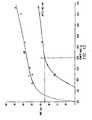
- Fig. 15shows the radius of detection (ROD) in centimeters (cm) measured for the various core masses in grams (g) for the embodiments of Figs. 12-13 placed in surrounded by air or mounted on a cylinder with a protective cap.
- the mass of ferritemay result in the reduction of the detuning effect caused by a relatively large and proximate metallic mass. This is demonstrated by the reduction in ROD caused by placement of the annular ferrite core on a gas cylinder equipped with a protective cap.
Landscapes
- Engineering & Computer Science (AREA)
- Physics & Mathematics (AREA)
- General Physics & Mathematics (AREA)
- Theoretical Computer Science (AREA)
- Computer Hardware Design (AREA)
- Microelectronics & Electronic Packaging (AREA)
- Computer Networks & Wireless Communication (AREA)
- Electromagnetism (AREA)
- Near-Field Transmission Systems (AREA)
Description
- The invention relates to ring antennas for resonant circuits, which may be usedto identify objects, and to interrogation systems including such ring antennas. Such resonantcircuits may be used in transponders, readers, or the like. In particular, the invention relates toannular antennas for resonant circuits, which may be mounted on and/or around metalcontainers, and to interrogation systems including resonant circuits and such annular antennas.
- Wireless systems have been developed for remote monitoring of variousparameters. Such systems may be used to identify or detect the presence, location, andnumber of objects at a distance. For example, an interrogation apparatus or system may use aradio frequency (RF) signal to request information from a transponder, also known as aresponder device or apparatus. This information may include a preset code for identificationpurposes, or the requested information may be based on measurements from a sensor.
- Transponders may include electronic or integrated circuits and resonant circuitsused for receiving RF signals from an interrogation device or apparatus and for transmittingRF signals containing monitoring information back to an interrogation device or apparatus.Such resonant circuits include a capacitance, an inductance and a resistance. Further, energyfrom the signals received by the resonant circuit may be stored and used to power the resonantcircuit, thus eliminating the need for power supplies in many applications. Such stored poweralso may be used to excite the resonant circuit for transmission of signals back to theinterrogation device or apparatus.
- To further conserve energy, resonant circuits have been designed, which neednot be continuously excited. Instead, the circuit may be initially excited and then periodicallysupplied with additional energy to maintain oscillation. This maintenance energy is suppliedbecause the resonant circuits may suffer various losses. Other components of the transponderalso may cause a damping of the oscillation, thus, resulting in decay of the oscillation. The re-excitationof a resonant circuit with maintenance energy pulses is referred to as "plucking."
- With known transponders, the plucking function may be initiated after a fixednumber of oscillations. For example, the plucking function may be initiated after every eightoscillations (also referred to as "ringings") of the resonant circuit. Unfortunately, the quality-factor,i.e., the Q factor, of resonant circuits is not constant from transponder to transponder,and thus, the frequency of the plucking function may require modifications for properoperation. For example, a plucking function that is performed every eight oscillations,i.e., 8-pluck,may be insufficient to maintain oscillations in a low Q factor resonant circuit,e.g., acircuit with a Q factor in the range of about 10 to 40. Moreover, the Q factor of individualresonant circuits may fluctuate, due to the presence of metal or circuits used to dampen othernearby resonators.
- Small, inexpensive, and highly reliable transponders are generally desirable.However, transponders may be used in a wide range of applications, and thus, differenttransponders are commonly designed for different applications. Various transponderembodiments are described in U.S. Patent No. 5,053,774;Similarly, their associated antennas are designed to meet a variety of needs. Theneed for different designs causes transponder and antenna costs to increase and may causetheir reliability to decrease.
- Nevertheless, air coil transponders are sensitive to the close proximity of metal.Distances constituting close proximity are relative to the mass and the geometry of metalobjects and to the particular type of metal from which the objects are made. The closeproximity of metal tends to detune the antenna circuits, and metal, especially iron and alloyscontaining iron, tend to dampen the RF signal. Although ferrite rod transponders are generallyless sensitive to the close proximity of metal when the rod is positioned parallel to the metalsurface, field orientation is often not optimal in such antenna applications. In general, metalobjects in a range of less than about 15 mm of the antenna of an air coil transponder areconsidered in close proximity, and metal objects in a range of between about 8 to 10 mm ofthe antenna of a ferrite rod transponder are deemed to be within close proximity. Pot coretransponders represent an alternative configuration to air coil transponders, but thesetransponders may attain only limited read ranges due to size and design constraints.
- Document EP-A-586 083 describes a ring antennaaccording to the preamble of
claim 1. - Thus, a need has arisen for ring antennas with ring,e.g., annular, cores, for usewith resonant circuits. Such ring antennas may be mounted on and/or around objects, such asmetallic containers, for identifying such objects. A further need has arisen for ring antennasthat are capable of extended ranges,e.g., ranges of about 20 to 40 cm, for transmission orreception, or both. These antennas also may be less influenced by the metal from the objects,and their construction also may maintain relatively high, antenna Q factors,e.g., an antennawith a Q factor in the range of about 60 to 100.
- In an embodiment, the invention is a ring antenna for resonant circuits, whichmay be used in transponders, readers, and the like, for identifying objects,e.g., metalliccontainers. The antenna may comprise a core ring having at least one core surfacecorresponding to at least one surface of the object and may be made from a ferromagneticmaterial. For example, the core may have a L-shaped, U-shaped, or rectangular cross-section(hereinafter referred to as L-shaped, U-shaped, and rectangular cores). Further, the core ringmay be annular or another closed geometric shape, such as rectangular, triangular, orcurvilinear, with a closed perimeter surrounding an open center, and the closed perimeter andthe open center may have different shapes. Suitable ferromagnetic materials may include iron,cobalt, and nickel, and their alloys, including steel.Moreover, the antenna may include a wire coil including wire made from an electricallyconductive material, such as gold, silver, aluminum, nickel, and copper and copper alloys,wound around at least a portion of the core, and a shield made from a non-magnetic material,such as gold, silver, aluminum, copper, and lead, affixed to the at least one core surface, andseparating the core from the surface of the object. For example, the shield may have a L-shaped,U-shaped, or I-shaped cross-section and may be affixed the surfaces of the coreopposite the surface or surfaces supporting the coil (hereinafter referred to as L-shaped, U-shaped,and I-shaped shields).
- In another embodiment, the invention is an interrogation system for identifyingobjects comprising a resonant circuit, such as may be included in a transponder, a reader, orthe like, coupled to a ring antenna. The antenna may comprise a core ring having at least onecore surface corresponding to at least one surface of the object and may be made from aferromagnetic material. A wire coil including wire made from an electrically conductivematerial is wound around at least a portion of the core, and a shield made from a non-magnetic metallic material is affixed to the at least one core surface and separates the corefrom the surface of the object.
- It is a technical advantage of the antenna of the present invention that it isshaped as a ring and may be placed on and/or around metal objects, such as containers,e.g.,kegs, bottles, and gas cylinders, and mounted on vehicles. It further is a technical advantagethat the field lines of the antenna are oriented substantially perpendicular to the metallicsurface of such objects for superior coupling to the antenna. In particular, it is a technicaladvantage of this invention that the Q factor obtained for the ring antenna is substantiallyindependent of the proximity of metal. In addition, technical advantages of the antennainclude that the antenna is simple to manufacture; that it may be readily modified into variousdimensions and shapes to conform to the configurations of a variety of metallic objects,e.g.,containers; and that it may be affixed to the metallic object with a right coupling orientation.
- Other objects and technical advantages will be apparent to persons of ordinaryskill in the art from the following detailed description of the invention and the accompanyingdrawings.
- The scope of the patent is defined by thefeatures stated in the claims and thus the patent does notcover embodiments of the antenna having a core ring madefrom fenite or iron oxyde materials
- For a more complete understanding of the present invention, and theadvantages thereof, reference is now made to the following descriptions taken in conjunctionwith the accompanying drawings, in which:
- Fig. 1 depicts a cut-away, perspective view of an antenna according to the presentinvention with an L-shaped core and an L-shaped shield;
- Fig. 2 depicts a cross-sectional view of a second embodiment of the antenna of thisinvention;
- Fig. 3 depicts a cross-sectional view of a third embodiment of the antenna of thisinvention;
- Fig. 4 depicts a cross-sectional view of a fourth embodiment of the antenna of thisinvention;
- Fig. 5 depicts a cross-sectional view of a fifth embodiment of the antenna of thisinvention;
- Fig. 6 depicts a cross-sectional view of a sixth embodiment of the antenna of thisinvention;
- Fig. 7 depicts a cross-sectional view of a seventh embodiment of the antenna of thisinvention;
- Fig. 8a depicts a cross-sectional view of an eighth embodiment of the antenna of thisinvention, andFig. 8b depicts an end on view of the core and shield of the antenna ofFig. 8aalong the LineVIIIb-VIIIb;
- Fig. 9a depicts a cross-sectional view of a ninth embodiment of the antenna of thisinvention, with a U-shaped core and a L-shaped shield, andFig. 9b depicts a cross-sectionalview of the antenna of this invention; with a U-shaped core and a U-shaped shield;
- Fig. 10 depicts a cross-sectional view ofa tenth embodiment of the antenna of thisinvention;
- Fig. 11 depicts a cross-sectional view of an eleventh embodiment of the antenna of thisinvention, with a core having a rectangular cross-section and a I-shaped shield, for mountingaround metal objects;
- Fig. 12 depicts a cross-sectional view of a twelfth embodiment of the antenna of thisinvention;
- Fig. 13 depicts a cross-sectional view of the antenna ofFig. 12 mounted on a metalgas cylinder;
- Figs. 14a-b depict perspective views of core rings with other closed geometric shapes;and
- Fig. 15 is a graph depicting the radius of detection (ROD) in centimeters (cm)measured for various masses in grams (g) for embodiments ofFigs. 12-13.
- Referring toFig. 1, a cut-away, perspective view of an
annular antenna 10according to the present invention is shown with an annular core 11 with a L-shaped cross-sectionand anannular shield 13 with a L-shaped cross-section. Unlike a pot core antenna, acore ring,e.g., an annular core, has a dosed perimeter surrounding an open center. Annularcore 11 has twocore surfaces 11a' and 11b', which correspond to two surfaces of a metalliccontainer (not shown), and a first and asecond portion 11a and 11b, respectively. Moreover,annular core 11 is made from ferrite and has an axis x indicated by a dashed line. As shown inFigs. 2-8, the relative thickness and height of a core ring, and consequently, its mass, varywith the configuration,i.e., the size and shape, of the container, on which it is mounted, andthe desired transmission or reception characteristics, or both, of the antenna or the system. - Referring again toFig. 1, a wire may be wound around
first portion 11a toform awire coil 12 which rests upon second portion 11b of annular core 11.Coil 12 includeswire made from an electrically conductive material, such as copper or copper alloys. Althoughonly a few winds of wire 12a are shown incoil 12, the number of winds may vary, forexample, with the size of the coil desired and the diameter of wire 12a and the desiredinductance (L) for tuning the associated resonant circuit. Further,shield 13 is made from anon-magnetic material, such as aluminum, and, as noted above, is affixed to first and secondcore surfaces 11a' and 11b' of annular core 11.Shield 13 separates core 11 from thecorresponding surfaces of the container (not shown). Such shields may have at least onevertical or cylindrical portion and will have such a cylindrical portion if the antenna is only tobe placed around, rather than on, a metallic object. If the antenna is mounted on a metallicobject, the shield has a horizontal or disc portion. For example, a screw or rivet may be usedto fix a ring antenna and a resonant circuit, such as in a disc-shaped transponder, to a metallicobject. The screw or rivet may be positioned at the center axis of the disc-shapedtransponder. - As noted above,Figs. 2-8 depict various embodiments of the inventiondesigned to conform to the size and shape of various metallic containers, on which they maybe mounted, and to achieve desired transmission or reception characteristics, or both. Forexample,Fig. 2 depicts a
ring antenna 20, which has anair gap 24 separating a first coresurface 21a' from a cylindrical portion of an L-shapedshield 23.Shield 23, however, is indirect contact with asecond portion 21b of acore ring 21 at asecond core surface 21b'. - Referring toFig. 3, an
antenna 30 is shown in which anair gap 34 is createdbetween acoil 32 and a first portion 31a of acore ring 31.Coil 32 rests on a second portion31b ofcore 31, and an L-shapedshield 33 contacts first portion 31a and second portion 31b ofcore 31 at a first and a second core surface 31a' and 31b', respectively. - Figs. 4 and5 depict
antennas antenna 40, an L-shapedshield 43 extends beyond the upper end of a first portion 41a and theouter end ofsecond portion 41b of acore ring 41. Further, acoil 42 is generally orientedalong first portion 41a ofcore 41. Similarly, with respect to ringantenna 50, an L-shapedshield 53 extends beyond the upper end of afirst portion 51a and the outer end ofsecondportion 51b of acore ring 51. However, acoil 52 is generally oriented alongsecond portion 51b ofcore 51. As noted above, the relative thickness, height, and orientation of the coil,e.g., coils 41 and 51, may vary with the size and shape of the container, on which an antenna ismounted, and with the desired transmission or reception characteristics, or both.Thus, referring toFigs. 6 and7,ring antennas antennas coils second portions 21b and 31b of core rings 21 and 31, respectively. - Referring toFig. 8a, an
annular antenna 80 includes anannular core 81 and ashield 83 affixed to asecond portion 81b ofcore 81. Acoil 82 rests onsecond portion 81b ofcore 81, and anelectronic circuit 86 is mounted on the periphery of and is electricallyconnected tocoil 82. Such electronic circuits may include a signal generator to generate anoscillating signal and a transistor coupled to and activated and deactivated by the signalgenerator. They may further include a discriminator for passing signals within a selectedfrequency range and a processor,e.g., a microprocessor, to process signals passed by thediscriminator.Coil 82,core 81, andcircuit 86 are contained within a protective andelectromagneticallytransparent encasement 85, and anair gap 87 is created betweenencasement 85 andfirst portion 81a ofcore 81. In one embodiment,encasement 85 may havean inner diameter (ID) of about 31mm, an outer diameter (OD) about 60 mm, and a height (h)of about 10 mm.Fig. 8b depicts an overhead, cross-sectional view ofFig. 8a along theLineVIIIb-VIIIb. - Figs. 9a-b and12 depict alternative embodiments of the ring antenna of thepresent invention, in which the core ring has a U-shaped cross-section. Referring toFig. 9a, an annular,
U-shaped core 91 includes a first portion 91 a, asecond portion 91b, and athirdportion 91c; acoil 92 rests onsecond portion 91b between first portion 91a andthird portion 91c. An L-shaped shield 93a contacts first portion 91a andsecond portion 91b ofcore 91 at afirst and a second core surface 91a' and 91b', respectively.Coil 92 andcore 91 again may becontained within a protective and electromagneticallytransparent encasement 95, and anairgap 97 may be created betweenencasement 95 and the portion ofshield 93 in contact withfirst portion 91a ofcore 91. Alternatively, referring toFig. 9b, aU-shaped shield 93b maycontact a first portion 91a, asecond portion 91b, and athird portion 91c of aU-shaped core 91 at a first, a second, and a third core surfaces 91a', 91b', and 91c', respectively. In addition,as shown inFig.9b air gaps 94a and 94c also may be formed between the cylindrical portionsofU-shaped shield 93b andsecond portion 91b andthird portion 91c ofcore 91. Such U-shapedshields further reduce or eliminate the influence of nearby metal objects on the antenna. - Similarly,Fig. 10 depicts still another embodiment of the ring antenna of thepresent invention, in which the core ring again has a U-shaped cross-section, but is oriented90° from that shown inFigs. 9a-b. InFig. 10, an annular, U-shaped core 101 includes a firstportion 101a, a
second portion 101b, and athird portion 101c; acoil 102 rests onsecondportion 101b below first portion 101a andthird portion 101c. An L-shapedshield 103contacts first portion 101a andsecond portion 101b of core 101 at a first and a second coresurfaces 101a' and 101b', respectively. - Fig. 12 depicts yet another embodiment of an annular, U-shaped antennasimilar to that shown inFig. 9a. However,
antenna 120 shown inFig. 12 is enclosed in anencasement 125 with angled exterior upper corners, and, further,encasement 125 encloses anelectronic circuit 126.Fig. 13 showsantenna 120 mounted on a bottle, such as a metallic,e.g., steel,gas cylinder 210.Antenna 120 is placed aroundneck 212 ofgas cylinder 210, andencasement 125 is mounted onshoulders 214 ofgas cylinder 210. Further,gas cylinder 210may be fitted with aframework 300 to protectantenna 120 andgas cylinder neck 212 fromdamage during storage or transportation. - Referring toFig 11, a
ring antenna 110 is depicted, which has arectangularcore ring 111.Core 111 includes abase portion 111a and an inner perimeter portion 11b, towhich I-shapedshield 113 is affixed tocore 111 at afirst core surface 111a', acoil 112 restsagainstouter perimeter portion 111c.Antenna 110 is suitable for mounting around metalobjects, such as metal containers. - As noted above, the relative thickness and height of the core ring, andconsequently, its mass, may vary with the size and shape of the container on which or aroundwhich it is mounted, and the desired transmission or reception characteristics, or both. Forexample, Table I shows dimensions of the annular ferrite cores of embodiments of the ringantennas ofFigs. 2-5, 9a, and to12.
FERRITE MASS rho: 3.6 DIMENSIONS L-shaped U-shaped Figure ID (mm) OD (mm) h (mm) d (mm) m (g) m (g) Fig. 2 17 34.4 15 4 20.6 Fig. 3 39.4 60.2 15 4 45.0 Fig. 4 39.4 60.2 8 2 17.3 Fig. 5 37 60.2 10 3 28.6 Fig. 9a-b 37 60.2 10 3 42.2 Fig. 12 34 48 7 1.5 12.5 - As noted above, a core ring may be annular or another closed geometric shape,such as rectangular, triangular, or curvilinear, with a closed perimeter surrounding an opencenter. Moreover, the core perimeter and the open center may have different shapes.Referring toFigs. 14a-b, two, substantially L-shaped
cores 140a and 140b are depicted. Withrespect toFig 14a, core 140a has a rectangular open center 141a and an annular closedperimeter 142a, and with respect toFig. 14b,core 140b has a rectangularopen center 141band an annularclosed perimeter 142b. Other possible combinations of perimeter and opencenter shapes are apparent from these figures. - The invention may be further clarified by consideration of the followingexamples, which are intended to be purely exemplary of the use of the invention. Further, thesuperior results revealed by the following tests are exemplary of the performance ofembodiments of the ring antenna.
- Various tests were performed on an antenna similar in configuration to thatdescribed inFigs. 9a-b. The antenna had an interior diameter of about 44.5 mm, an outerdiameter of about 51 mm, a height of about 8 mm, and a depth of about 1.85 mm. The coilwas formed of one hundred and twelve (112) winds of copper wire with a diameter of about0.2 mm. These tests included measurements of antennas placed around and on a variety ofbottles and surfaces. Further, the antennas were tested with inside cylindrical portions oroutside cylindrical portions, or both, or without any cylindrical portions.
- Tables IIA and IIB depict the results of the tests of (1) the coil alone without acore, (2) the coil surrounding a ferrite core, (3) the coil surrounding a ferrite core with analuminum disc portion, (4) the antenna mounted on a steel gas cylinder, (5) the antennamounted on a steel gas cylinder with a gas valve, (6) the antenna mounted on a steel gascylinder with a protective cap, (7) the antenna mounted on a steel gas cylinder with a gas valveand a protective cap, (8) the antenna on an aluminum plate, (9) the antenna on a steel plateand, (10) the antenna surrounding a steel core placed on a steel plate. The bottle described inTables IIA and IIB is a steel gas cylinder with a height of about 60 cm and a diameter of about15 cm. Moreover, the bottle may be fitted with a brass valve commonly used on gas,e.g.,oxygen, cylinders or with a tulip-shaped steel cap, or both. The programmed frequency is thefrequency to which the resonant circuit is tuned, for example, by use of switching capacitors.The offset is the difference in frequency measured between the resonance frequency of atransponder,i.e., of the resonant circuit, and the reference frequency of a given interrogationsystem. For example, the reference frequency used in the examples described in Tables IIAand IIB was about 134 kHz. These tables demonstrate the superior results achieved by thepresent invention.
Configuration=Figs. 9a-b no cylindrical portion inside cylindrical portion L Q ΔF ROD L Q ΔF ROD mH kHz cm mH kHz cm Configuration 8-pluck 8-pluck Coil 1.004 55.8 Coil + Ferrite 2.611 101.5 -2.7 2.489 76.4 0.5 Coil + ferrite + Al disc portion 2.509 89.4 0 0 59 2.415 70 2.5 0 64 Bottle 2.502 88.3 0.2 0.2 57 2.394 70.0 3.1 0.6 60 Bottle + valve 2.414 78.6 2.5 2.5 69 2.362 71.3 3.9 1.4 62 Bottle + cap 2.472 89.6 1.0 1.0 37 2.382 72.6 3.4 0.9 39 Bottle + valve + cap 2.399 80.7 2.9 2.9 34 2.352 73.6 4.2 1.7 36 On Al plate 2.478 94.6 0.8 0.8 43 2.390 71.4 3.2 0.7 46 On Steel plate 2.488 82.7 0.6 0.6 45 2.410 67.7 2.6 0.1 46 Steel plate with corc 2.420 27.2 2.4 2.4 0 2.384 38.2 3.3 0.8 0 Programmed freq. (kHz) 131.3 132.5 Offset (Hz) -2700 -1500 Configuration =Fig. 9a-b outside cylindrical portion in + outside cylindrical portions L Q ΔF ROD L Q ΔF ROD mH kHz cm mH kHz cm Configuration 8-pluck 8-pluck Coil Coil + Ferrite 2.413 70.5 2.6 2.333 62.8 4.7 Coil + ferrite + Al disc portion 2.391 72.2 3.2 0 46 2.316 62.4 5.2 0 46 Bottle 2.348 72.7 4.3 1.1 46 2271 62.5 6.4 1.2 47 Bottle + valve 2.286 69.2 6 2.8 45 2.252 64.9 6.9 1.7 44 Bottle + cap 2.372 74.3 3.7 0.5 25 2.305 64.4 5.5 0.3 25 Bottle + valve + cap 2.314 71.0 5.2 2.1 26 2.287 66.3 5.9 0.8 23 On Al plate 2.377 74.6 3.5 0.4 37 2.306 62.6 5.4 0.3 36 On Steel plate 2.404 72.9 2.8 -0.3 37 2.333 64 4.7 -0.5 36 Steel plate with core 2.343 29.9 4.4 1.3 0 2.306 42.4 5.4 0.3 0 Programmed freq. (kHz) 132.1 133.4 Offset (Hz) -1900 -600 - In addition, Tables IIA and IIB describe test results for the embodiment ofFigs. 9a-b in the dimensions described above. In particular, these tables show the Δ freq.(kHz) measured under the various test conditions described above, the Q factor, and radius ofdetection (ROD) in centimeters (cm). Finally,Fig. 15 shows the radius of detection (ROD) incentimeters (cm) measured for the various core masses in grams (g) for the embodiments ofFigs. 12-13 placed in surrounded by air or mounted on a cylinder with a protective cap. Asshown inFig. 15, the mass of ferrite may result in the reduction of the detuning effect causedby a relatively large and proximate metallic mass. This is demonstrated by the reduction inROD caused by placement of the annular ferrite core on a gas cylinder equipped with aprotective cap.
- Other embodiments of the invention will be apparent to those skilled in the artfrom a consideration of this specification or practice of the invention disclosed herein. It is intended that the specification and examples be considered as exemplary only.
Claims (11)
- A ring antenna (10) for a resonant circuit, wherein the ring antenna(10) is mounted on or around a metallic object (210) such as a container, andcomprises:the ring antenna (10) beingcharacterised in that:a wire coil (12) including wire (12a) made from an electricallyconductive material wound around at least a portion (11a) of a core ring (11)having at least one core surface (11a', 11b') corresponding to at least one surfaceof said object (210),the core ring (11) is made from a ferromagnetic material ; and- the ring antenna (10) comprises a shield (13) made from a non-magneticmaterial, affixed to said at least one core surface (11a', 11b'), andseparating said core ring (11) from said surface of said object (210).
- The antenna (10) of claim 1, wherein said core (11) has a U-shapedcross-section and includes a first portion (91a) and second and third portions(91b, 91c).
- The antenna (10) of claim 1, wherein said core (11) has a L-shapedcross-section and includes a first portion (11a) and a second portion (11b).
- The antenna (10) of claim 1, wherein said core (11) has arectangular cross-section and includes a first portion (111a) and an innerperimeter portion (111b).
- The antenna (10) of claim 2-3, wherein said shield (13) has a L-shapedcross-section and is affixed to at least one of said portions of said core.
- The antenna (10) of claim 2, wherein said shield has a U-shapedcross-section and is affixed to at least one of said portions (91a, 91b, 91c, 11a,11b) of said core (11).
- The antenna (10) of claim 4, wherein said shield (13) has an I-shapedcross-section and is affixed to one of said portions (111a) of said core(11).
- The antenna (10) of claims 1-6, wherein said ferromagnetic materialis selected from the group consisting of iron, steel, cobalt and nickel.
- The antenna (10) of claims 1-7, wherein said electrically conductivematerial is selected from a group consisting of gold, silver, aluminium, nickel, andcopper and copper alloys.
- The antenna (10) of claims 1-8, wherein said non-magnetic materialis selected from the group consisting of copper, aluminium, silver, and lead.
- An interrogation system for identifying objects comprising aresonant circuit coupled to the antenna (10) of claims 1-9.
Priority Applications (4)
| Application Number | Priority Date | Filing Date | Title |
|---|---|---|---|
| AT95402936TATE279028T1 (en) | 1995-12-22 | 1995-12-22 | RING ANTENNAS FOR RESONANCE CIRCUITS |
| EP95402936AEP0782214B1 (en) | 1995-12-22 | 1995-12-22 | Ring antennas for resonant cicuits |
| DE69533622TDE69533622T2 (en) | 1995-12-22 | 1995-12-22 | Ring antennas for resonant circuits |
| US08/770,021US5864323A (en) | 1995-12-22 | 1996-12-19 | Ring antennas for resonant circuits |
Applications Claiming Priority (2)
| Application Number | Priority Date | Filing Date | Title |
|---|---|---|---|
| EP95402936AEP0782214B1 (en) | 1995-12-22 | 1995-12-22 | Ring antennas for resonant cicuits |
| US08/770,021US5864323A (en) | 1995-12-22 | 1996-12-19 | Ring antennas for resonant circuits |
Publications (2)
| Publication Number | Publication Date |
|---|---|
| EP0782214A1 EP0782214A1 (en) | 1997-07-02 |
| EP0782214B1true EP0782214B1 (en) | 2004-10-06 |
Family
ID=26140606
Family Applications (1)
| Application Number | Title | Priority Date | Filing Date |
|---|---|---|---|
| EP95402936AExpired - LifetimeEP0782214B1 (en) | 1995-12-22 | 1995-12-22 | Ring antennas for resonant cicuits |
Country Status (2)
| Country | Link |
|---|---|
| US (1) | US5864323A (en) |
| EP (1) | EP0782214B1 (en) |
Cited By (2)
| Publication number | Priority date | Publication date | Assignee | Title |
|---|---|---|---|---|
| CN105526495A (en)* | 2015-12-09 | 2016-04-27 | 上海炘璞电子科技有限公司 | Intelligent gas cylinder with radio frequency identification labels |
| CN105550737A (en)* | 2015-12-09 | 2016-05-04 | 上海炘璞电子科技有限公司 | Intelligent gas cylinder with radio frequency identification tag |
Families Citing this family (205)
| Publication number | Priority date | Publication date | Assignee | Title |
|---|---|---|---|---|
| US8352400B2 (en) | 1991-12-23 | 2013-01-08 | Hoffberg Steven M | Adaptive pattern recognition based controller apparatus and method and human-factored interface therefore |
| US10361802B1 (en) | 1999-02-01 | 2019-07-23 | Blanding Hovenweep, Llc | Adaptive pattern recognition based control system and method |
| US20040239521A1 (en)* | 2001-12-21 | 2004-12-02 | Zierolf Joseph A. | Method and apparatus for determining position in a pipe |
| US7283061B1 (en)* | 1998-08-28 | 2007-10-16 | Marathon Oil Company | Method and system for performing operations and for improving production in wells |
| DE19857717B4 (en)* | 1998-12-15 | 2012-08-02 | Air Liquide Deutschland Gmbh | Device for receiving electronic data carriers for compressed gas cylinders and corresponding compressed gas cylinder |
| DE19857722B4 (en)* | 1998-12-15 | 2012-08-02 | Air Liquide Deutschland Gmbh | Device with electronic data carrier for identification and labeling of compressed gas cylinders and corresponding compressed gas cylinder |
| US7904187B2 (en) | 1999-02-01 | 2011-03-08 | Hoffberg Steven M | Internet appliance system and method |
| US8538801B2 (en) | 1999-02-19 | 2013-09-17 | Exxonmobile Research & Engineering Company | System and method for processing financial transactions |
| US7571139B1 (en) | 1999-02-19 | 2009-08-04 | Giordano Joseph A | System and method for processing financial transactions |
| DE19911034C5 (en)* | 1999-03-12 | 2006-11-02 | Air Liquide Deutschland Gmbh | Holding device with exchangeable transponder unit |
| US7239226B2 (en) | 2001-07-10 | 2007-07-03 | American Express Travel Related Services Company, Inc. | System and method for payment using radio frequency identification in contact and contactless transactions |
| US7837116B2 (en) | 1999-09-07 | 2010-11-23 | American Express Travel Related Services Company, Inc. | Transaction card |
| US7156301B1 (en) | 1999-09-07 | 2007-01-02 | American Express Travel Related Services Company, Inc. | Foldable non-traditionally-sized RF transaction card system and method |
| US7070112B2 (en) | 1999-09-07 | 2006-07-04 | American Express Travel Related Services Company, Inc. | Transparent transaction device |
| US7093767B2 (en) | 1999-09-07 | 2006-08-22 | American Express Travel Related Services Company, Inc. | System and method for manufacturing a punch-out RFID transaction device |
| US7889052B2 (en) | 2001-07-10 | 2011-02-15 | Xatra Fund Mx, Llc | Authorizing payment subsequent to RF transactions |
| US7306158B2 (en) | 2001-07-10 | 2007-12-11 | American Express Travel Related Services Company, Inc. | Clear contactless card |
| US8140658B1 (en) | 1999-10-06 | 2012-03-20 | Borgia/Cummins, Llc | Apparatus for internetworked wireless integrated network sensors (WINS) |
| WO2001031741A1 (en)* | 1999-10-27 | 2001-05-03 | Motorola Inc. | Method and apparatus for reducing the amount of interference between two antennae positioned near each other in an electric field radio frequency identification reader system |
| US7172112B2 (en) | 2000-01-21 | 2007-02-06 | American Express Travel Related Services Company, Inc. | Public/private dual card system and method |
| US7268668B2 (en) | 2003-05-09 | 2007-09-11 | American Express Travel Related Services Company, Inc. | Systems and methods for managing multiple accounts on a RF transaction instrument |
| US8429041B2 (en)* | 2003-05-09 | 2013-04-23 | American Express Travel Related Services Company, Inc. | Systems and methods for managing account information lifecycles |
| US8543423B2 (en) | 2002-07-16 | 2013-09-24 | American Express Travel Related Services Company, Inc. | Method and apparatus for enrolling with multiple transaction environments |
| US7627531B2 (en) | 2000-03-07 | 2009-12-01 | American Express Travel Related Services Company, Inc. | System for facilitating a transaction |
| US6628237B1 (en)* | 2000-03-25 | 2003-09-30 | Marconi Communications Inc. | Remote communication using slot antenna |
| BRPI0112645B1 (en)* | 2000-07-19 | 2016-07-05 | Hanex Co Ltd | housing structure and installation structure for a radio frequency identification indicator and communication method using a radio frequency identification indicator |
| JP2002290131A (en) | 2000-12-18 | 2002-10-04 | Mitsubishi Materials Corp | Antenna for transponder |
| US20020130817A1 (en)* | 2001-03-16 | 2002-09-19 | Forster Ian J. | Communicating with stackable objects using an antenna array |
| US7014100B2 (en)* | 2001-04-27 | 2006-03-21 | Marathon Oil Company | Process and assembly for identifying and tracking assets |
| US7650314B1 (en) | 2001-05-25 | 2010-01-19 | American Express Travel Related Services Company, Inc. | System and method for securing a recurrent billing transaction |
| US7725427B2 (en) | 2001-05-25 | 2010-05-25 | Fred Bishop | Recurrent billing maintenance with radio frequency payment devices |
| US7542942B2 (en) | 2001-07-10 | 2009-06-02 | American Express Travel Related Services Company, Inc. | System and method for securing sensitive information during completion of a transaction |
| US9024719B1 (en) | 2001-07-10 | 2015-05-05 | Xatra Fund Mx, Llc | RF transaction system and method for storing user personal data |
| US8635131B1 (en) | 2001-07-10 | 2014-01-21 | American Express Travel Related Services Company, Inc. | System and method for managing a transaction protocol |
| US7059531B2 (en) | 2001-07-10 | 2006-06-13 | American Express Travel Related Services Company, Inc. | Method and system for smellprint recognition biometrics on a fob |
| US7312707B1 (en) | 2001-07-10 | 2007-12-25 | American Express Travel Related Services Company, Inc. | System and method for authenticating a RF transaction using a transaction account routing number |
| US7746215B1 (en) | 2001-07-10 | 2010-06-29 | Fred Bishop | RF transactions using a wireless reader grid |
| US7154375B2 (en) | 2001-07-10 | 2006-12-26 | American Express Travel Related Services Company, Inc. | Biometric safeguard method with a fob |
| US7121471B2 (en) | 2001-07-10 | 2006-10-17 | American Express Travel Related Services Company, Inc. | Method and system for DNA recognition biometrics on a fob |
| US7827106B2 (en) | 2001-07-10 | 2010-11-02 | American Express Travel Related Services Company, Inc. | System and method for manufacturing a punch-out RFID transaction device |
| US8538863B1 (en) | 2001-07-10 | 2013-09-17 | American Express Travel Related Services Company, Inc. | System and method for facilitating a transaction using a revolving use account associated with a primary account |
| US20040233037A1 (en)* | 2001-07-10 | 2004-11-25 | American Express Travel Related Services Company, Inc. | Method and system for iris scan recognition biometrics on a fob |
| US7996324B2 (en) | 2001-07-10 | 2011-08-09 | American Express Travel Related Services Company, Inc. | Systems and methods for managing multiple accounts on a RF transaction device using secondary identification indicia |
| US7503480B2 (en) | 2001-07-10 | 2009-03-17 | American Express Travel Related Services Company, Inc. | Method and system for tracking user performance |
| US8960535B2 (en) | 2001-07-10 | 2015-02-24 | Iii Holdings 1, Llc | Method and system for resource management and evaluation |
| US7543738B1 (en) | 2001-07-10 | 2009-06-09 | American Express Travel Related Services Company, Inc. | System and method for secure transactions manageable by a transaction account provider |
| US7303120B2 (en)* | 2001-07-10 | 2007-12-04 | American Express Travel Related Services Company, Inc. | System for biometric security using a FOB |
| US7805378B2 (en) | 2001-07-10 | 2010-09-28 | American Express Travel Related Servicex Company, Inc. | System and method for encoding information in magnetic stripe format for use in radio frequency identification transactions |
| US7228155B2 (en) | 2001-07-10 | 2007-06-05 | American Express Travel Related Services Company, Inc. | System and method for remotely initializing a RF transaction |
| US7429927B2 (en) | 2001-07-10 | 2008-09-30 | American Express Travel Related Services Company, Inc. | System and method for providing and RFID transaction device |
| US7668750B2 (en) | 2001-07-10 | 2010-02-23 | David S Bonalle | Securing RF transactions using a transactions counter |
| US8548927B2 (en)* | 2001-07-10 | 2013-10-01 | Xatra Fund Mx, Llc | Biometric registration for facilitating an RF transaction |
| US8001054B1 (en) | 2001-07-10 | 2011-08-16 | American Express Travel Related Services Company, Inc. | System and method for generating an unpredictable number using a seeded algorithm |
| US7360689B2 (en) | 2001-07-10 | 2008-04-22 | American Express Travel Related Services Company, Inc. | Method and system for proffering multiple biometrics for use with a FOB |
| US7705732B2 (en) | 2001-07-10 | 2010-04-27 | Fred Bishop | Authenticating an RF transaction using a transaction counter |
| US9454752B2 (en) | 2001-07-10 | 2016-09-27 | Chartoleaux Kg Limited Liability Company | Reload protocol at a transaction processing entity |
| US7493288B2 (en) | 2001-07-10 | 2009-02-17 | Xatra Fund Mx, Llc | RF payment via a mobile device |
| US7119659B2 (en) | 2001-07-10 | 2006-10-10 | American Express Travel Related Services Company, Inc. | Systems and methods for providing a RF transaction device for use in a private label transaction |
| US7463133B2 (en) | 2001-07-10 | 2008-12-09 | American Express Travel Related Services Company, Inc. | Systems and methods for providing a RF transaction device operable to store multiple distinct calling card accounts |
| US20040236699A1 (en) | 2001-07-10 | 2004-11-25 | American Express Travel Related Services Company, Inc. | Method and system for hand geometry recognition biometrics on a fob |
| US7762457B2 (en) | 2001-07-10 | 2010-07-27 | American Express Travel Related Services Company, Inc. | System and method for dynamic fob synchronization and personalization |
| US7925535B2 (en) | 2001-07-10 | 2011-04-12 | American Express Travel Related Services Company, Inc. | System and method for securing RF transactions using a radio frequency identification device including a random number generator |
| US20090008441A1 (en)* | 2001-07-10 | 2009-01-08 | Xatra Fund Mx, Llc | Tracking rf transaction activity using a transaction device identifier |
| US8279042B2 (en) | 2001-07-10 | 2012-10-02 | Xatra Fund Mx, Llc | Iris scan biometrics on a payment device |
| US8294552B2 (en) | 2001-07-10 | 2012-10-23 | Xatra Fund Mx, Llc | Facial scan biometrics on a payment device |
| US7249112B2 (en) | 2002-07-09 | 2007-07-24 | American Express Travel Related Services Company, Inc. | System and method for assigning a funding source for a radio frequency identification device |
| US9031880B2 (en)* | 2001-07-10 | 2015-05-12 | Iii Holdings 1, Llc | Systems and methods for non-traditional payment using biometric data |
| US7135978B2 (en)* | 2001-09-14 | 2006-11-14 | Calypso Medical Technologies, Inc. | Miniature resonating marker assembly |
| DE10149126A1 (en) | 2001-10-05 | 2003-04-10 | Flexchip Ag | Production of a screen used for a transponder comprises applying ferromagnetic particles to a region of the substrate having the spatial expansion of the antenna structure of a transponder, aligning the ferromagnetic particles, etc. |
| US6812707B2 (en) | 2001-11-27 | 2004-11-02 | Mitsubishi Materials Corporation | Detection element for objects and detection device using the same |
| US6690278B2 (en) | 2001-12-28 | 2004-02-10 | Gas Technology Institute | Electronic marker for metallic valve box covers |
| WO2003091943A1 (en)* | 2002-04-24 | 2003-11-06 | Marconi Intellectual Property (Us) Inc | Energy source recharging device and method |
| ATE474287T1 (en) | 2002-04-24 | 2010-07-15 | Mineral Lassen Llc | PRODUCTION METHOD FOR A WIRELESS COMMUNICATION DEVICE AND PRODUCTION APPARATUS |
| WO2003091746A1 (en)* | 2002-04-24 | 2003-11-06 | Marconi Intellectual Property (Us) Inc | Rechargeable interrogation reader device and method |
| AU2003233007A1 (en)* | 2002-04-24 | 2003-11-10 | Marconi Intellectual Property (Us) Inc | Energy source with a slot antenna formed in the body |
| AUPS201102A0 (en)* | 2002-04-30 | 2002-06-06 | Tagsys Australia Pty. Ltd. | A miniture 3d rfid tag |
| US7587756B2 (en) | 2002-07-09 | 2009-09-08 | American Express Travel Related Services Company, Inc. | Methods and apparatus for a secure proximity integrated circuit card transactions |
| US6805287B2 (en) | 2002-09-12 | 2004-10-19 | American Express Travel Related Services Company, Inc. | System and method for converting a stored value card to a credit card |
| EP1429417B9 (en) | 2002-11-21 | 2006-10-25 | Optosys SA | Reader and transponder within housings |
| US7893840B2 (en)* | 2003-03-03 | 2011-02-22 | Veroscan, Inc. | Interrogator and interrogation system employing the same |
| US8174366B2 (en)* | 2003-03-03 | 2012-05-08 | Veroscan, Inc. | Interrogator and interrogation system employing the same |
| US7019650B2 (en) | 2003-03-03 | 2006-03-28 | Caducys, L.L.C. | Interrogator and interrogation system employing the same |
| US8542717B2 (en) | 2003-03-03 | 2013-09-24 | Veroscan, Inc. | Interrogator and interrogation system employing the same |
| US7764178B2 (en)* | 2003-03-03 | 2010-07-27 | Veroscan, Inc. | Interrogator and interrogation system employing the same |
| US8063760B2 (en)* | 2003-03-03 | 2011-11-22 | Veroscan, Inc. | Interrogator and interrogation system employing the same |
| US20050230109A1 (en)* | 2004-04-15 | 2005-10-20 | Reinhold Kammann | Apparatus identification systems and methods |
| US7268667B2 (en) | 2003-05-09 | 2007-09-11 | American Express Travel Related Services Company, Inc. | Systems and methods for providing a RF transaction device operable to store multiple distinct accounts |
| US6992630B2 (en)* | 2003-10-28 | 2006-01-31 | Harris Corporation | Annular ring antenna |
| WO2005086072A1 (en) | 2004-03-03 | 2005-09-15 | Caducys, L.L.C. | Interrogator and interrogation system employing the same |
| KR20050094082A (en)* | 2004-03-22 | 2005-09-27 | (주)알에프캠프 | Eyelet for a radio frequency identification |
| US7318550B2 (en) | 2004-07-01 | 2008-01-15 | American Express Travel Related Services Company, Inc. | Biometric safeguard method for use with a smartcard |
| US7314165B2 (en) | 2004-07-01 | 2008-01-01 | American Express Travel Related Services Company, Inc. | Method and system for smellprint recognition biometrics on a smartcard |
| US7307535B2 (en)* | 2004-07-27 | 2007-12-11 | Datamars S.A. | Air coil RF transponder and method of making same |
| US7501948B2 (en) | 2004-09-29 | 2009-03-10 | Lone Star Ip Holdings, Lp | Interrogation system employing prior knowledge about an object to discern an identity thereof |
| GB0425008D0 (en)* | 2004-11-12 | 2004-12-15 | Petrowell Ltd | Method and apparatus |
| DE102004061633A1 (en)* | 2004-12-17 | 2006-06-29 | Lossau, Harald, Dr. | Container with transponder |
| FR2884681B1 (en)* | 2005-04-15 | 2007-06-22 | St Microelectronics Sa | ANTENNA FOR ELECTRONIC LABEL |
| JP2006339757A (en)* | 2005-05-31 | 2006-12-14 | Denso Corp | Antenna coil, method of manufacturing communication substrate module, and card type wireless device |
| JP4189683B2 (en)* | 2005-05-31 | 2008-12-03 | 株式会社デンソー | Antenna coil, method for manufacturing communication board module, and card-type radio |
| US7825543B2 (en) | 2005-07-12 | 2010-11-02 | Massachusetts Institute Of Technology | Wireless energy transfer |
| CN101860089B (en) | 2005-07-12 | 2013-02-06 | 麻省理工学院 | wireless non-radiative energy transfer |
| US20070035383A1 (en)* | 2005-08-09 | 2007-02-15 | Roemerman Steven D | Radio frequency identification interrogation systems and methods of operating the same |
| WO2007087447A2 (en)* | 2006-01-25 | 2007-08-02 | Health Beacens, Inc. | Surgical procedure |
| WO2007123767A1 (en)* | 2006-03-31 | 2007-11-01 | Raytheon Company | Methods and apparatus for reducing radio frequency interference for collocated antennas |
| US7850893B2 (en) | 2006-12-01 | 2010-12-14 | Rexam Healthcare Packaging Inc. | Molded plastic container and preform having insert-molded RFID tag |
| US10262168B2 (en) | 2007-05-09 | 2019-04-16 | Weatherford Technology Holdings, Llc | Antenna for use in a downhole tubular |
| US8115448B2 (en) | 2007-06-01 | 2012-02-14 | Michael Sasha John | Systems and methods for wireless power |
| US9421388B2 (en) | 2007-06-01 | 2016-08-23 | Witricity Corporation | Power generation for implantable devices |
| US8120484B2 (en) | 2007-06-14 | 2012-02-21 | Rexam Healthcare Packaging Inc. | Closure and package with RFID kernel tag and boost antenna |
| US10119377B2 (en)* | 2008-03-07 | 2018-11-06 | Weatherford Technology Holdings, Llc | Systems, assemblies and processes for controlling tools in a well bore |
| US9194227B2 (en) | 2008-03-07 | 2015-11-24 | Marathon Oil Company | Systems, assemblies and processes for controlling tools in a wellbore |
| US9396867B2 (en) | 2008-09-27 | 2016-07-19 | Witricity Corporation | Integrated resonator-shield structures |
| US8946938B2 (en) | 2008-09-27 | 2015-02-03 | Witricity Corporation | Safety systems for wireless energy transfer in vehicle applications |
| US9601261B2 (en) | 2008-09-27 | 2017-03-21 | Witricity Corporation | Wireless energy transfer using repeater resonators |
| US9093853B2 (en) | 2008-09-27 | 2015-07-28 | Witricity Corporation | Flexible resonator attachment |
| US9160203B2 (en) | 2008-09-27 | 2015-10-13 | Witricity Corporation | Wireless powered television |
| US8937408B2 (en) | 2008-09-27 | 2015-01-20 | Witricity Corporation | Wireless energy transfer for medical applications |
| US8947186B2 (en) | 2008-09-27 | 2015-02-03 | Witricity Corporation | Wireless energy transfer resonator thermal management |
| US8907531B2 (en) | 2008-09-27 | 2014-12-09 | Witricity Corporation | Wireless energy transfer with variable size resonators for medical applications |
| US8901779B2 (en) | 2008-09-27 | 2014-12-02 | Witricity Corporation | Wireless energy transfer with resonator arrays for medical applications |
| US9318922B2 (en) | 2008-09-27 | 2016-04-19 | Witricity Corporation | Mechanically removable wireless power vehicle seat assembly |
| US8957549B2 (en) | 2008-09-27 | 2015-02-17 | Witricity Corporation | Tunable wireless energy transfer for in-vehicle applications |
| US9744858B2 (en) | 2008-09-27 | 2017-08-29 | Witricity Corporation | System for wireless energy distribution in a vehicle |
| US9246336B2 (en) | 2008-09-27 | 2016-01-26 | Witricity Corporation | Resonator optimizations for wireless energy transfer |
| US20110043049A1 (en)* | 2008-09-27 | 2011-02-24 | Aristeidis Karalis | Wireless energy transfer with high-q resonators using field shaping to improve k |
| US9515494B2 (en) | 2008-09-27 | 2016-12-06 | Witricity Corporation | Wireless power system including impedance matching network |
| US9601266B2 (en) | 2008-09-27 | 2017-03-21 | Witricity Corporation | Multiple connected resonators with a single electronic circuit |
| US8912687B2 (en) | 2008-09-27 | 2014-12-16 | Witricity Corporation | Secure wireless energy transfer for vehicle applications |
| US8933594B2 (en) | 2008-09-27 | 2015-01-13 | Witricity Corporation | Wireless energy transfer for vehicles |
| US9577436B2 (en) | 2008-09-27 | 2017-02-21 | Witricity Corporation | Wireless energy transfer for implantable devices |
| US20100277121A1 (en)* | 2008-09-27 | 2010-11-04 | Hall Katherine L | Wireless energy transfer between a source and a vehicle |
| US8901778B2 (en) | 2008-09-27 | 2014-12-02 | Witricity Corporation | Wireless energy transfer with variable size resonators for implanted medical devices |
| US9105959B2 (en) | 2008-09-27 | 2015-08-11 | Witricity Corporation | Resonator enclosure |
| US9035499B2 (en) | 2008-09-27 | 2015-05-19 | Witricity Corporation | Wireless energy transfer for photovoltaic panels |
| US8598743B2 (en) | 2008-09-27 | 2013-12-03 | Witricity Corporation | Resonator arrays for wireless energy transfer |
| US20110074346A1 (en)* | 2009-09-25 | 2011-03-31 | Hall Katherine L | Vehicle charger safety system and method |
| US8643326B2 (en) | 2008-09-27 | 2014-02-04 | Witricity Corporation | Tunable wireless energy transfer systems |
| US9601270B2 (en) | 2008-09-27 | 2017-03-21 | Witricity Corporation | Low AC resistance conductor designs |
| US9544683B2 (en) | 2008-09-27 | 2017-01-10 | Witricity Corporation | Wirelessly powered audio devices |
| US8963488B2 (en) | 2008-09-27 | 2015-02-24 | Witricity Corporation | Position insensitive wireless charging |
| US20100259110A1 (en)* | 2008-09-27 | 2010-10-14 | Kurs Andre B | Resonator optimizations for wireless energy transfer |
| US8482158B2 (en) | 2008-09-27 | 2013-07-09 | Witricity Corporation | Wireless energy transfer using variable size resonators and system monitoring |
| US9065423B2 (en) | 2008-09-27 | 2015-06-23 | Witricity Corporation | Wireless energy distribution system |
| US8928276B2 (en) | 2008-09-27 | 2015-01-06 | Witricity Corporation | Integrated repeaters for cell phone applications |
| US9106203B2 (en) | 2008-09-27 | 2015-08-11 | Witricity Corporation | Secure wireless energy transfer in medical applications |
| US9184595B2 (en) | 2008-09-27 | 2015-11-10 | Witricity Corporation | Wireless energy transfer in lossy environments |
| US8922066B2 (en) | 2008-09-27 | 2014-12-30 | Witricity Corporation | Wireless energy transfer with multi resonator arrays for vehicle applications |
| US8497601B2 (en) | 2008-09-27 | 2013-07-30 | Witricity Corporation | Wireless energy transfer converters |
| US8362651B2 (en) | 2008-10-01 | 2013-01-29 | Massachusetts Institute Of Technology | Efficient near-field wireless energy transfer using adiabatic system variations |
| US8973584B2 (en) | 2009-02-13 | 2015-03-10 | Health Beacons, Inc. | Method and apparatus for locating passive integrated transponder tags |
| US8850899B2 (en) | 2010-04-15 | 2014-10-07 | Marathon Oil Company | Production logging processes and systems |
| US9112272B2 (en) | 2010-08-12 | 2015-08-18 | Feinics Amatech Teoranta | Antenna modules for dual interface smart cards, booster antenna configurations, and methods |
| US9602168B2 (en) | 2010-08-31 | 2017-03-21 | Witricity Corporation | Communication in wireless energy transfer systems |
| US9035774B2 (en) | 2011-04-11 | 2015-05-19 | Lone Star Ip Holdings, Lp | Interrogator and system employing the same |
| US9948145B2 (en) | 2011-07-08 | 2018-04-17 | Witricity Corporation | Wireless power transfer for a seat-vest-helmet system |
| CN108110907B (en) | 2011-08-04 | 2022-08-02 | 韦特里西提公司 | Tunable wireless power supply architecture |
| US10733494B2 (en) | 2014-08-10 | 2020-08-04 | Féinics Amatech Teoranta | Contactless metal card constructions |
| US10518518B2 (en) | 2013-01-18 | 2019-12-31 | Féinics Amatech Teoranta | Smart cards with metal layer(s) and methods of manufacture |
| EP2754222B1 (en) | 2011-09-09 | 2015-11-18 | Witricity Corporation | Foreign object detection in wireless energy transfer systems |
| US20130062966A1 (en) | 2011-09-12 | 2013-03-14 | Witricity Corporation | Reconfigurable control architectures and algorithms for electric vehicle wireless energy transfer systems |
| US9318257B2 (en) | 2011-10-18 | 2016-04-19 | Witricity Corporation | Wireless energy transfer for packaging |
| CA2853824A1 (en) | 2011-11-04 | 2013-05-10 | Witricity Corporation | Wireless energy transfer modeling tool |
| US8669909B2 (en)* | 2011-11-30 | 2014-03-11 | Panasonic Corporation | Antenna, antenna apparatus, and communication apparatus |
| JP2015508987A (en) | 2012-01-26 | 2015-03-23 | ワイトリシティ コーポレーションWitricity Corporation | Wireless energy transmission with reduced field |
| JP6090307B2 (en)* | 2012-03-30 | 2017-03-08 | 日立金属株式会社 | Near field communication antenna, antenna module, and wireless communication device |
| US9343922B2 (en) | 2012-06-27 | 2016-05-17 | Witricity Corporation | Wireless energy transfer for rechargeable batteries |
| US9287607B2 (en) | 2012-07-31 | 2016-03-15 | Witricity Corporation | Resonator fine tuning |
| US10552722B2 (en) | 2014-08-10 | 2020-02-04 | Féinics Amatech Teoranta | Smartcard with coupling frame antenna |
| US10824931B2 (en) | 2012-08-30 | 2020-11-03 | Féinics Amatech Teoranta | Contactless smartcards with multiple coupling frames |
| US9595378B2 (en) | 2012-09-19 | 2017-03-14 | Witricity Corporation | Resonator enclosure |
| EP2909912B1 (en) | 2012-10-19 | 2022-08-10 | WiTricity Corporation | Foreign object detection in wireless energy transfer systems |
| US9842684B2 (en) | 2012-11-16 | 2017-12-12 | Witricity Corporation | Systems and methods for wireless power system with improved performance and/or ease of use |
| US10599972B2 (en) | 2013-01-18 | 2020-03-24 | Féinics Amatech Teoranta | Smartcard constructions and methods |
| US11354558B2 (en) | 2013-01-18 | 2022-06-07 | Amatech Group Limited | Contactless smartcards with coupling frames |
| US11354560B2 (en) | 2013-01-18 | 2022-06-07 | Amatech Group Limited | Smartcards with multiple coupling frames |
| US10977542B2 (en) | 2013-01-18 | 2021-04-13 | Amtech Group Limited Industrial Estate | Smart cards with metal layer(s) and methods of manufacture |
| US11551051B2 (en) | 2013-01-18 | 2023-01-10 | Amatech Group Limiied | Coupling frames for smartcards with various module opening shapes |
| US8939153B1 (en) | 2013-03-15 | 2015-01-27 | Health Beacons, Inc. | Transponder strings |
| WO2014191123A1 (en)* | 2013-05-28 | 2014-12-04 | Féinics Amatech Teoranta | Antenna modules for dual interface smartcards, booster antenna configurations, and methods |
| JP2015002440A (en)* | 2013-06-14 | 2015-01-05 | 富士通株式会社 | Antenna module and terminal device |
| US9857821B2 (en) | 2013-08-14 | 2018-01-02 | Witricity Corporation | Wireless power transfer frequency adjustment |
| US9780573B2 (en) | 2014-02-03 | 2017-10-03 | Witricity Corporation | Wirelessly charged battery system |
| US9952266B2 (en) | 2014-02-14 | 2018-04-24 | Witricity Corporation | Object detection for wireless energy transfer systems |
| US9842687B2 (en) | 2014-04-17 | 2017-12-12 | Witricity Corporation | Wireless power transfer systems with shaped magnetic components |
| US9892849B2 (en) | 2014-04-17 | 2018-02-13 | Witricity Corporation | Wireless power transfer systems with shield openings |
| US9837860B2 (en) | 2014-05-05 | 2017-12-05 | Witricity Corporation | Wireless power transmission systems for elevators |
| JP2017518018A (en) | 2014-05-07 | 2017-06-29 | ワイトリシティ コーポレーションWitricity Corporation | Foreign object detection in wireless energy transmission systems |
| US9954375B2 (en) | 2014-06-20 | 2018-04-24 | Witricity Corporation | Wireless power transfer systems for surfaces |
| US10574091B2 (en) | 2014-07-08 | 2020-02-25 | Witricity Corporation | Enclosures for high power wireless power transfer systems |
| CN107258046B (en) | 2014-07-08 | 2020-07-17 | 无线电力公司 | Resonator equalization in wireless power transfer systems |
| WO2016032910A1 (en) | 2014-08-24 | 2016-03-03 | Health Beacons, Inc. | Probe for determining magnetic marker locations |
| US9779865B2 (en)* | 2014-10-17 | 2017-10-03 | The Arizona Board Of Regents On Behalf Of The University Of Arizona | Voltage-controlled magnetic devices |
| US10068465B2 (en) | 2014-10-22 | 2018-09-04 | Mitutoyo Corporation | Battery-less data transmission module accessory for portable and handheld metrology devices |
| DE102014117725A1 (en) | 2014-12-02 | 2016-06-02 | Aquis Wasser-Luft-Systeme Gmbh, Lindau, Zweigniederlassung Rebstein | Filter for insertion into a water storage tank of a household appliance, in particular a beverage machine |
| US9843217B2 (en) | 2015-01-05 | 2017-12-12 | Witricity Corporation | Wireless energy transfer for wearables |
| US10248899B2 (en) | 2015-10-06 | 2019-04-02 | Witricity Corporation | RFID tag and transponder detection in wireless energy transfer systems |
| US9929721B2 (en) | 2015-10-14 | 2018-03-27 | Witricity Corporation | Phase and amplitude detection in wireless energy transfer systems |
| WO2017070227A1 (en) | 2015-10-19 | 2017-04-27 | Witricity Corporation | Foreign object detection in wireless energy transfer systems |
| WO2017070009A1 (en) | 2015-10-22 | 2017-04-27 | Witricity Corporation | Dynamic tuning in wireless energy transfer systems |
| US10075019B2 (en) | 2015-11-20 | 2018-09-11 | Witricity Corporation | Voltage source isolation in wireless power transfer systems |
| WO2017136491A1 (en) | 2016-02-02 | 2017-08-10 | Witricity Corporation | Controlling wireless power transfer systems |
| CN114123540B (en) | 2016-02-08 | 2024-08-20 | 韦特里西提公司 | Variable capacitance device and high-power wireless energy transmission system |
| WO2019006376A1 (en) | 2017-06-29 | 2019-01-03 | Witricity Corporation | Protection and control of wireless power systems |
| TWI749994B (en)* | 2021-01-07 | 2021-12-11 | 陸詰科技股份有限公司 | Wireless radio frequency identification device and packaging method thereof |
| KR102745066B1 (en)* | 2023-03-22 | 2024-12-20 | 주식회사 대현텔레메트리 | A Small and Circular Type of an Antenna with an Enhanced Inductance |
Family Cites Families (11)
| Publication number | Priority date | Publication date | Assignee | Title |
|---|---|---|---|---|
| US2740113A (en)* | 1952-01-03 | 1956-03-27 | Bendix Aviat Corp | Magnetic antenna systems |
| US4839659A (en)* | 1988-08-01 | 1989-06-13 | The United States Of America As Represented By The Secretary Of The Army | Microstrip phase scan antenna array |
| JPH05218726A (en)* | 1991-11-13 | 1993-08-27 | Seiko Epson Corp | Ferrite antenna |
| EP0554581B1 (en)* | 1992-02-05 | 1997-05-28 | Texas Instruments Incorporated | Method for producing a flat flexible antenna core for a chip transponder to be incorporated in a badge or similar object, and a thus produced antenna core |
| GB9216303D0 (en)* | 1992-07-31 | 1992-09-16 | Hughes Microelectronics Europa | Collar transponder |
| GB9220409D0 (en)* | 1992-09-28 | 1992-11-11 | Texas Instruments Holland | Shielded transponder |
| CA2123062A1 (en)* | 1994-03-09 | 1995-09-10 | John R. Meeks | Antenna coil assembly for an automobile transponder key system |
| EP0677887A1 (en)* | 1994-04-13 | 1995-10-18 | Texas Instruments Incorporated | Built-in chip transponder with antenna circuit |
| US5694139A (en)* | 1994-06-28 | 1997-12-02 | Sony Corporation | Short-distance communication antenna and methods of manufacturing and using the short-distance communication antenna |
| US5625370A (en)* | 1994-07-25 | 1997-04-29 | Texas Instruments Incorporated | Identification system antenna with impedance transformer |
| JP2624187B2 (en)* | 1994-08-24 | 1997-06-25 | 日産自動車株式会社 | Key cylinder device for automobile |
- 1995
- 1995-12-22EPEP95402936Apatent/EP0782214B1/ennot_activeExpired - Lifetime
- 1996
- 1996-12-19USUS08/770,021patent/US5864323A/ennot_activeExpired - Fee Related
Cited By (2)
| Publication number | Priority date | Publication date | Assignee | Title |
|---|---|---|---|---|
| CN105526495A (en)* | 2015-12-09 | 2016-04-27 | 上海炘璞电子科技有限公司 | Intelligent gas cylinder with radio frequency identification labels |
| CN105550737A (en)* | 2015-12-09 | 2016-05-04 | 上海炘璞电子科技有限公司 | Intelligent gas cylinder with radio frequency identification tag |
Also Published As
| Publication number | Publication date |
|---|---|
| EP0782214A1 (en) | 1997-07-02 |
| US5864323A (en) | 1999-01-26 |
Similar Documents
| Publication | Publication Date | Title |
|---|---|---|
| EP0782214B1 (en) | Ring antennas for resonant cicuits | |
| AU2005291987B2 (en) | Method and system for tracking containers having metallic portions, covers for containers having metallic portions, tags for use with container having metallic portions and methods of calibrating such tags | |
| US7317426B2 (en) | Core antenna for EAS and RFID applications | |
| US5883376A (en) | Device for contactless, inductive power and data transmission, and preferred use thereof for identifying gas cylinders | |
| US7245219B2 (en) | RFID tag for an object having metallic portions, tag coupler and method thereof | |
| EP2166617B1 (en) | Wireless ic device | |
| US6828941B2 (en) | Wireless communication device and method | |
| US7889145B2 (en) | Arrangement with a transponder and a metal element | |
| KR19980041936A (en) | Anti-theft Tag | |
| JP2005210223A (en) | Antenna device | |
| EP0590589B1 (en) | Transponder antenna with shield | |
| GB2288103A (en) | RF coupler for a shielded transponder | |
| EP2743865A1 (en) | RFID tag, system and method for identification of samples at cryogenic temperatures | |
| US8081078B2 (en) | Universal tracking assembly | |
| IL152093A (en) | Electronic label | |
| EP1760828A1 (en) | Contactless integrated circuit device | |
| EP1548876A2 (en) | Nanocrystalline core antenna for EAS and RFID applications | |
| US20240078407A1 (en) | Self-tuning radio-frequency identification tags | |
| EP1727079A3 (en) | Identifying system for overlapped tags | |
| JP2002529833A (en) | Container with sensor | |
| DE69533622T2 (en) | Ring antennas for resonant circuits | |
| CN112292784A (en) | Metal container containing UHF RFID tag | |
| HK1116598A (en) | Core antenna for eas and rfid applications | |
| MX2007003768A (en) | Method and system for tracking containers having metallic portions, covers for containers having metallic portions, tags for use wtih container having metallic portions and methods of calibrating such tags. |
Legal Events
| Date | Code | Title | Description |
|---|---|---|---|
| PUAI | Public reference made under article 153(3) epc to a published international application that has entered the european phase | Free format text:ORIGINAL CODE: 0009012 | |
| AK | Designated contracting states | Kind code of ref document:A1 Designated state(s):AT BE CH DE DK ES FR GB GR IE IT LI LU MC NL PT SE | |
| 17P | Request for examination filed | Effective date:19971224 | |
| 17Q | First examination report despatched | Effective date:20010116 | |
| GRAP | Despatch of communication of intention to grant a patent | Free format text:ORIGINAL CODE: EPIDOSNIGR1 | |
| GRAS | Grant fee paid | Free format text:ORIGINAL CODE: EPIDOSNIGR3 | |
| GRAA | (expected) grant | Free format text:ORIGINAL CODE: 0009210 | |
| PGFP | Annual fee paid to national office [announced via postgrant information from national office to epo] | Ref country code:FR Payment date:20040916 Year of fee payment:10 | |
| AK | Designated contracting states | Kind code of ref document:B1 Designated state(s):AT BE CH DE DK ES FR GB GR IE IT LI LU MC NL PT SE | |
| PG25 | Lapsed in a contracting state [announced via postgrant information from national office to epo] | Ref country code:SE Free format text:LAPSE BECAUSE OF FAILURE TO SUBMIT A TRANSLATION OF THE DESCRIPTION OR TO PAY THE FEE WITHIN THE PRESCRIBED TIME-LIMIT Effective date:20041006 Ref country code:NL Free format text:LAPSE BECAUSE OF FAILURE TO SUBMIT A TRANSLATION OF THE DESCRIPTION OR TO PAY THE FEE WITHIN THE PRESCRIBED TIME-LIMIT Effective date:20041006 Ref country code:LI Free format text:LAPSE BECAUSE OF FAILURE TO SUBMIT A TRANSLATION OF THE DESCRIPTION OR TO PAY THE FEE WITHIN THE PRESCRIBED TIME-LIMIT Effective date:20041006 Ref country code:IT Free format text:LAPSE BECAUSE OF FAILURE TO SUBMIT A TRANSLATION OF THE DESCRIPTION OR TO PAY THE FEE WITHIN THE PRE;WARNING: LAPSES OF ITALIAN PATENTS WITH EFFECTIVE DATE BEFORE 2007 MAY HAVE OCCURRED AT ANY TIME BEFORE 2007. THE CORRECT EFFECTIVE DATE MAY BE DIFFERENT FROM THE ONE RECORDED.SCRIBED TIME-LIMIT Effective date:20041006 Ref country code:CH Free format text:LAPSE BECAUSE OF FAILURE TO SUBMIT A TRANSLATION OF THE DESCRIPTION OR TO PAY THE FEE WITHIN THE PRESCRIBED TIME-LIMIT Effective date:20041006 Ref country code:BE Free format text:LAPSE BECAUSE OF FAILURE TO SUBMIT A TRANSLATION OF THE DESCRIPTION OR TO PAY THE FEE WITHIN THE PRESCRIBED TIME-LIMIT Effective date:20041006 Ref country code:AT Free format text:LAPSE BECAUSE OF FAILURE TO SUBMIT A TRANSLATION OF THE DESCRIPTION OR TO PAY THE FEE WITHIN THE PRESCRIBED TIME-LIMIT Effective date:20041006 | |
| REG | Reference to a national code | Ref country code:GB Ref legal event code:FG4D | |
| REG | Reference to a national code | Ref country code:CH Ref legal event code:EP | |
| REG | Reference to a national code | Ref country code:IE Ref legal event code:FG4D | |
| REF | Corresponds to: | Ref document number:69533622 Country of ref document:DE Date of ref document:20041111 Kind code of ref document:P | |
| PGFP | Annual fee paid to national office [announced via postgrant information from national office to epo] | Ref country code:DE Payment date:20041206 Year of fee payment:10 | |
| PGFP | Annual fee paid to national office [announced via postgrant information from national office to epo] | Ref country code:GB Payment date:20041209 Year of fee payment:10 | |
| PG25 | Lapsed in a contracting state [announced via postgrant information from national office to epo] | Ref country code:LU Free format text:LAPSE BECAUSE OF NON-PAYMENT OF DUE FEES Effective date:20041222 Ref country code:IE Free format text:LAPSE BECAUSE OF NON-PAYMENT OF DUE FEES Effective date:20041222 | |
| PG25 | Lapsed in a contracting state [announced via postgrant information from national office to epo] | Ref country code:MC Free format text:LAPSE BECAUSE OF NON-PAYMENT OF DUE FEES Effective date:20041231 | |
| PG25 | Lapsed in a contracting state [announced via postgrant information from national office to epo] | Ref country code:GR Free format text:LAPSE BECAUSE OF FAILURE TO SUBMIT A TRANSLATION OF THE DESCRIPTION OR TO PAY THE FEE WITHIN THE PRESCRIBED TIME-LIMIT Effective date:20050106 Ref country code:DK Free format text:LAPSE BECAUSE OF FAILURE TO SUBMIT A TRANSLATION OF THE DESCRIPTION OR TO PAY THE FEE WITHIN THE PRESCRIBED TIME-LIMIT Effective date:20050106 | |
| PG25 | Lapsed in a contracting state [announced via postgrant information from national office to epo] | Ref country code:ES Free format text:LAPSE BECAUSE OF FAILURE TO SUBMIT A TRANSLATION OF THE DESCRIPTION OR TO PAY THE FEE WITHIN THE PRESCRIBED TIME-LIMIT Effective date:20050117 | |
| NLV1 | Nl: lapsed or annulled due to failure to fulfill the requirements of art. 29p and 29m of the patents act | ||
| REG | Reference to a national code | Ref country code:CH Ref legal event code:PL | |
| ET | Fr: translation filed | ||
| PLBE | No opposition filed within time limit | Free format text:ORIGINAL CODE: 0009261 | |
| STAA | Information on the status of an ep patent application or granted ep patent | Free format text:STATUS: NO OPPOSITION FILED WITHIN TIME LIMIT | |
| REG | Reference to a national code | Ref country code:IE Ref legal event code:MM4A | |
| 26N | No opposition filed | Effective date:20050707 | |
| PG25 | Lapsed in a contracting state [announced via postgrant information from national office to epo] | Ref country code:GB Free format text:LAPSE BECAUSE OF NON-PAYMENT OF DUE FEES Effective date:20051222 | |
| PG25 | Lapsed in a contracting state [announced via postgrant information from national office to epo] | Ref country code:DE Free format text:LAPSE BECAUSE OF NON-PAYMENT OF DUE FEES Effective date:20060701 | |
| GBPC | Gb: european patent ceased through non-payment of renewal fee | Effective date:20051222 | |
| PG25 | Lapsed in a contracting state [announced via postgrant information from national office to epo] | Ref country code:FR Free format text:LAPSE BECAUSE OF NON-PAYMENT OF DUE FEES Effective date:20060831 | |
| REG | Reference to a national code | Ref country code:FR Ref legal event code:ST Effective date:20060831 | |
| PG25 | Lapsed in a contracting state [announced via postgrant information from national office to epo] | Ref country code:PT Free format text:LAPSE BECAUSE OF NON-PAYMENT OF DUE FEES Effective date:20050306 |