EP0781406B1 - Position detectable strip for analyte detection - Google Patents
Position detectable strip for analyte detectionDownload PDFInfo
- Publication number
- EP0781406B1 EP0781406B1EP95933213AEP95933213AEP0781406B1EP 0781406 B1EP0781406 B1EP 0781406B1EP 95933213 AEP95933213 AEP 95933213AEP 95933213 AEP95933213 AEP 95933213AEP 0781406 B1EP0781406 B1EP 0781406B1
- Authority
- EP
- European Patent Office
- Prior art keywords
- strip
- passageway
- reaction zone
- reflectance
- insertion end
- Prior art date
- Legal status (The legal status is an assumption and is not a legal conclusion. Google has not performed a legal analysis and makes no representation as to the accuracy of the status listed.)
- Expired - Lifetime
Links
- 239000012491analyteSubstances0.000titleclaimsabstractdescription25
- 238000001514detection methodMethods0.000titleclaimsdescription37
- 238000012360testing methodMethods0.000claimsabstractdescription43
- 239000007788liquidSubstances0.000claimsabstractdescription16
- 238000006243chemical reactionMethods0.000claimsdescription57
- 238000003780insertionMethods0.000claimsdescription39
- 230000037431insertionEffects0.000claimsdescription39
- 230000013011matingEffects0.000claimsdescription5
- 239000004020conductorSubstances0.000claimsdescription4
- 210000004369bloodAnatomy0.000description34
- 239000008280bloodSubstances0.000description34
- 239000000463materialSubstances0.000description21
- 239000006163transport mediaSubstances0.000description18
- WQZGKKKJIJFFOK-GASJEMHNSA-NGlucoseNatural productsOC[C@H]1OC(O)[C@H](O)[C@@H](O)[C@@H]1OWQZGKKKJIJFFOK-GASJEMHNSA-N0.000description17
- 239000008103glucoseSubstances0.000description17
- 239000003153chemical reaction reagentSubstances0.000description16
- 238000000034methodMethods0.000description15
- 239000002131composite materialSubstances0.000description9
- 239000000975dyeSubstances0.000description9
- MHAJPDPJQMAIIY-UHFFFAOYSA-NHydrogen peroxideChemical compoundOOMHAJPDPJQMAIIY-UHFFFAOYSA-N0.000description8
- 102000004190EnzymesHuman genes0.000description6
- 108090000790EnzymesProteins0.000description6
- 229940088598enzymeDrugs0.000description6
- 230000008859changeEffects0.000description5
- 239000010410layerSubstances0.000description5
- -1polyethylenePolymers0.000description5
- 239000011148porous materialSubstances0.000description5
- 102000003992PeroxidasesHuman genes0.000description4
- 239000004698PolyethyleneSubstances0.000description4
- HVYWMOMLDIMFJA-DPAQBDIFSA-NcholesterolChemical compoundC1C=C2C[C@@H](O)CC[C@]2(C)[C@@H]2[C@@H]1[C@@H]1CC[C@H]([C@H](C)CCCC(C)C)[C@@]1(C)CC2HVYWMOMLDIMFJA-DPAQBDIFSA-N0.000description4
- 239000012528membraneSubstances0.000description4
- 239000000203mixtureSubstances0.000description4
- 230000003287optical effectEffects0.000description4
- 229920000728polyesterPolymers0.000description4
- 229920000573polyethylenePolymers0.000description4
- 239000000126substanceSubstances0.000description4
- PHOLIFLKGONSGY-CSKARUKUSA-N(e)-(3-methyl-1,3-benzothiazol-2-ylidene)hydrazineChemical compoundC1=CC=C2S\C(=N\N)N(C)C2=C1PHOLIFLKGONSGY-CSKARUKUSA-N0.000description3
- 108010015776Glucose oxidaseProteins0.000description3
- 239000004366Glucose oxidaseSubstances0.000description3
- 239000012790adhesive layerSubstances0.000description3
- WQZGKKKJIJFFOK-VFUOTHLCSA-Nbeta-D-glucoseChemical compoundOC[C@H]1O[C@@H](O)[C@H](O)[C@@H](O)[C@@H]1OWQZGKKKJIJFFOK-VFUOTHLCSA-N0.000description3
- 230000001747exhibiting effectEffects0.000description3
- 229940116332glucose oxidaseDrugs0.000description3
- 235000019420glucose oxidaseNutrition0.000description3
- 239000011159matrix materialSubstances0.000description3
- 229920000642polymerPolymers0.000description3
- 238000011002quantificationMethods0.000description3
- 239000000376reactantSubstances0.000description3
- 239000004094surface-active agentSubstances0.000description3
- 239000001856Ethyl celluloseSubstances0.000description2
- ZZSNKZQZMQGXPY-UHFFFAOYSA-NEthyl celluloseChemical compoundCCOCC1OC(OC)C(OCC)C(OCC)C1OC1C(O)C(O)C(OC)C(CO)O1ZZSNKZQZMQGXPY-UHFFFAOYSA-N0.000description2
- 239000004952PolyamideSubstances0.000description2
- XSQUKJJJFZCRTK-UHFFFAOYSA-NUreaChemical compoundNC(N)=OXSQUKJJJFZCRTK-UHFFFAOYSA-N0.000description2
- XLOMVQKBTHCTTD-UHFFFAOYSA-NZinc monoxideChemical compound[Zn]=OXLOMVQKBTHCTTD-UHFFFAOYSA-N0.000description2
- 230000009471actionEffects0.000description2
- 239000000853adhesiveSubstances0.000description2
- 230000001070adhesive effectEffects0.000description2
- 239000013060biological fluidSubstances0.000description2
- 235000012000cholesterolNutrition0.000description2
- 238000004040coloringMethods0.000description2
- 230000000295complement effectEffects0.000description2
- 229920001940conductive polymerPolymers0.000description2
- 210000003743erythrocyteAnatomy0.000description2
- 229920001249ethyl cellulosePolymers0.000description2
- 235000019325ethyl celluloseNutrition0.000description2
- 239000012530fluidSubstances0.000description2
- NOESYZHRGYRDHS-UHFFFAOYSA-NinsulinChemical compoundN1C(=O)C(NC(=O)C(CCC(N)=O)NC(=O)C(CCC(O)=O)NC(=O)C(C(C)C)NC(=O)C(NC(=O)CN)C(C)CC)CSSCC(C(NC(CO)C(=O)NC(CC(C)C)C(=O)NC(CC=2C=CC(O)=CC=2)C(=O)NC(CCC(N)=O)C(=O)NC(CC(C)C)C(=O)NC(CCC(O)=O)C(=O)NC(CC(N)=O)C(=O)NC(CC=2C=CC(O)=CC=2)C(=O)NC(CSSCC(NC(=O)C(C(C)C)NC(=O)C(CC(C)C)NC(=O)C(CC=2C=CC(O)=CC=2)NC(=O)C(CC(C)C)NC(=O)C(C)NC(=O)C(CCC(O)=O)NC(=O)C(C(C)C)NC(=O)C(CC(C)C)NC(=O)C(CC=2NC=NC=2)NC(=O)C(CO)NC(=O)CNC2=O)C(=O)NCC(=O)NC(CCC(O)=O)C(=O)NC(CCCNC(N)=N)C(=O)NCC(=O)NC(CC=3C=CC=CC=3)C(=O)NC(CC=3C=CC=CC=3)C(=O)NC(CC=3C=CC(O)=CC=3)C(=O)NC(C(C)O)C(=O)N3C(CCC3)C(=O)NC(CCCCN)C(=O)NC(C)C(O)=O)C(=O)NC(CC(N)=O)C(O)=O)=O)NC(=O)C(C(C)CC)NC(=O)C(CO)NC(=O)C(C(C)O)NC(=O)C1CSSCC2NC(=O)C(CC(C)C)NC(=O)C(NC(=O)C(CCC(N)=O)NC(=O)C(CC(N)=O)NC(=O)C(NC(=O)C(N)CC=1C=CC=CC=1)C(C)C)CC1=CN=CN1NOESYZHRGYRDHS-UHFFFAOYSA-N0.000description2
- 238000005259measurementMethods0.000description2
- 238000012544monitoring processMethods0.000description2
- 239000000178monomerSubstances0.000description2
- 230000007935neutral effectEffects0.000description2
- 108040007629peroxidase activity proteinsProteins0.000description2
- 229920002492poly(sulfone)Polymers0.000description2
- 229920002647polyamidePolymers0.000description2
- 230000008569processEffects0.000description2
- 239000000047productSubstances0.000description2
- XLYOFNOQVPJJNP-UHFFFAOYSA-NwaterSubstancesOXLYOFNOQVPJJNP-UHFFFAOYSA-N0.000description2
- FWEOQOXTVHGIFQ-UHFFFAOYSA-M8-anilinonaphthalene-1-sulfonateChemical compoundC=12C(S(=O)(=O)[O-])=CC=CC2=CC=CC=1NC1=CC=CC=C1FWEOQOXTVHGIFQ-UHFFFAOYSA-M0.000description1
- 241000228245Aspergillus nigerSpecies0.000description1
- OKTJSMMVPCPJKN-UHFFFAOYSA-NCarbonChemical compound[C]OKTJSMMVPCPJKN-UHFFFAOYSA-N0.000description1
- 229920000742CottonPolymers0.000description1
- PHOQVHQSTUBQQK-SQOUGZDYSA-ND-glucono-1,5-lactoneChemical compoundOC[C@H]1OC(=O)[C@H](O)[C@@H](O)[C@@H]1OPHOQVHQSTUBQQK-SQOUGZDYSA-N0.000description1
- LFQSCWFLJHTTHZ-UHFFFAOYSA-NEthanolChemical compoundCCOLFQSCWFLJHTTHZ-UHFFFAOYSA-N0.000description1
- 108010001336Horseradish PeroxidaseProteins0.000description1
- 239000004831Hot glueSubstances0.000description1
- 102000004877InsulinHuman genes0.000description1
- 108090001061InsulinProteins0.000description1
- 241000228143PenicilliumSpecies0.000description1
- 239000004743PolypropyleneSubstances0.000description1
- 239000004793PolystyreneSubstances0.000description1
- 206010047531Visual acuity reducedDiseases0.000description1
- 230000002378acidificating effectEffects0.000description1
- NIXOWILDQLNWCW-UHFFFAOYSA-Nacrylic acid groupChemical groupC(C=C)(=O)ONIXOWILDQLNWCW-UHFFFAOYSA-N0.000description1
- 230000003213activating effectEffects0.000description1
- 239000002313adhesive filmSubstances0.000description1
- 230000002411adverseEffects0.000description1
- HSFWRNGVRCDJHI-UHFFFAOYSA-Nalpha-acetyleneNatural productsC#CHSFWRNGVRCDJHI-UHFFFAOYSA-N0.000description1
- QVGXLLKOCUKJST-UHFFFAOYSA-Natomic oxygenChemical compound[O]QVGXLLKOCUKJST-UHFFFAOYSA-N0.000description1
- 238000005452bendingMethods0.000description1
- 239000004202carbamideSubstances0.000description1
- 229910052799carbonInorganic materials0.000description1
- 125000004432carbon atomChemical groupC*0.000description1
- 229920002678cellulosePolymers0.000description1
- 239000001913celluloseSubstances0.000description1
- 238000004140cleaningMethods0.000description1
- 238000009833condensationMethods0.000description1
- 230000005494condensationEffects0.000description1
- 238000012790confirmationMethods0.000description1
- 206010012601diabetes mellitusDiseases0.000description1
- 238000003745diagnosisMethods0.000description1
- 150000004985diaminesChemical class0.000description1
- 230000037213dietEffects0.000description1
- 235000005911dietNutrition0.000description1
- 201000010099diseaseDiseases0.000description1
- 208000037265diseases, disorders, signs and symptomsDiseases0.000description1
- 230000000694effectsEffects0.000description1
- 239000005038ethylene vinyl acetateSubstances0.000description1
- 238000011156evaluationMethods0.000description1
- 238000009472formulationMethods0.000description1
- 125000000524functional groupChemical group0.000description1
- 230000004927fusionEffects0.000description1
- 235000012209glucono delta-lactoneNutrition0.000description1
- 229960003681gluconolactoneDrugs0.000description1
- 108010046301glucose peroxidaseProteins0.000description1
- 239000000383hazardous chemicalSubstances0.000description1
- OEZPVSPULCMUQB-VRTOBVRTSA-Nhydron;(e)-(3-methyl-1,3-benzothiazol-2-ylidene)hydrazine;chlorideChemical compoundCl.C1=CC=C2S\C(=N\N)N(C)C2=C1OEZPVSPULCMUQB-VRTOBVRTSA-N0.000description1
- 230000001771impaired effectEffects0.000description1
- 230000000977initiatory effectEffects0.000description1
- 239000000976inkSubstances0.000description1
- 229940125396insulinDrugs0.000description1
- 150000003951lactamsChemical class0.000description1
- 239000004973liquid crystal related substanceSubstances0.000description1
- 238000010339medical testMethods0.000description1
- 239000002184metalSubstances0.000description1
- 229910052751metalInorganic materials0.000description1
- 238000012986modificationMethods0.000description1
- 230000004048modificationEffects0.000description1
- 230000004973motor coordinationEffects0.000description1
- 238000001579optical reflectometryMethods0.000description1
- 229910052760oxygenInorganic materials0.000description1
- 239000001301oxygenSubstances0.000description1
- 239000012466permeateSubstances0.000description1
- 210000002381plasmaAnatomy0.000description1
- 239000004033plasticSubstances0.000description1
- 229920003023plasticPolymers0.000description1
- 229920001197polyacetylenePolymers0.000description1
- 229920000767polyanilinePolymers0.000description1
- 229920000098polyolefinPolymers0.000description1
- 229920001155polypropylenePolymers0.000description1
- 229920000128polypyrrolePolymers0.000description1
- 229920002223polystyrenePolymers0.000description1
- 229920000123polythiophenePolymers0.000description1
- 238000002360preparation methodMethods0.000description1
- 238000002310reflectometryMethods0.000description1
- 238000005070samplingMethods0.000description1
- 238000010517secondary reactionMethods0.000description1
- 239000004065semiconductorSubstances0.000description1
- 210000002966serumAnatomy0.000description1
- 229920002994synthetic fiberPolymers0.000description1
- 238000010998test methodMethods0.000description1
- 229940126585therapeutic drugDrugs0.000description1
- 210000002700urineAnatomy0.000description1
- 239000011800void materialSubstances0.000description1
- 239000011787zinc oxideSubstances0.000description1
Images


Classifications
- G—PHYSICS
- G01—MEASURING; TESTING
- G01N—INVESTIGATING OR ANALYSING MATERIALS BY DETERMINING THEIR CHEMICAL OR PHYSICAL PROPERTIES
- G01N33/00—Investigating or analysing materials by specific methods not covered by groups G01N1/00 - G01N31/00
- G01N33/48—Biological material, e.g. blood, urine; Haemocytometers
- G01N33/50—Chemical analysis of biological material, e.g. blood, urine; Testing involving biospecific ligand binding methods; Immunological testing
- G01N33/52—Use of compounds or compositions for colorimetric, spectrophotometric or fluorometric investigation, e.g. use of reagent paper and including single- and multilayer analytical elements
- G—PHYSICS
- G01—MEASURING; TESTING
- G01N—INVESTIGATING OR ANALYSING MATERIALS BY DETERMINING THEIR CHEMICAL OR PHYSICAL PROPERTIES
- G01N21/00—Investigating or analysing materials by the use of optical means, i.e. using sub-millimetre waves, infrared, visible or ultraviolet light
- G01N21/84—Systems specially adapted for particular applications
- G01N21/8483—Investigating reagent band
- G—PHYSICS
- G01—MEASURING; TESTING
- G01N—INVESTIGATING OR ANALYSING MATERIALS BY DETERMINING THEIR CHEMICAL OR PHYSICAL PROPERTIES
- G01N33/00—Investigating or analysing materials by specific methods not covered by groups G01N1/00 - G01N31/00
- G01N33/48—Biological material, e.g. blood, urine; Haemocytometers
- G01N33/50—Chemical analysis of biological material, e.g. blood, urine; Testing involving biospecific ligand binding methods; Immunological testing
- G01N33/53—Immunoassay; Biospecific binding assay; Materials therefor
- G01N33/543—Immunoassay; Biospecific binding assay; Materials therefor with an insoluble carrier for immobilising immunochemicals
Definitions
- the present inventionrelates to a test device and method for the determination of analytes in aqueous fluids, particularly whole blood.
- itconcerns a test device and method for optically measuring the concentration of glucose in whole blood.
- Another popular blood glucose test methodemploys similar chemistry but uses, in place of the ethylcellulose-coated pad, a water-resistant film through which the enzymes and indicator are dispersed. This type of system is disclosed in United States Patent 3,630,957 issued December 28, 1971 to Rey et al.
- the sampleis allowed to remain in contact with the reagent pad for a specified time (typically one minute). Then, in the first case, the blood sample is washed off with a stream of water while in the second case, it is wiped off the film. The reagent pad or film is then blotted dry and evaluated. The evaluation of the analyte concentration is made either by comparing color generated with a color chart or by placing the pad or film in a diffuse reflectance instrument to read a color intensity value.
- Another problem that often exists in simple lay-operator determinationsis the necessity for initiating a timing sequence when blood is applied to a reagent pad.
- a userwill typically have pricked his or her finger to obtain a blood sample and will then be required to simultaneously apply the blood from the finger to a reagent pad while starting a timer with his or her other hand, thereby requiring the use of both hands simultaneously.
- Thisis particularly difficult since it is often necessary to ensure that the timer is started only when blood is applied to the reagent pad.
- All of the prior art methodsrequire additional manipulations or additional circuitry to achieve this result. Accordingly, simplification of this aspect of reflectance reading instruments is desirable.
- the reflectivity of the reaction zoneis then a measure of the presence and/or quantity of analyte present in the blood sample.
- this systemdoes not require a large sample of blood nor does it require the user to undertake timed manipulations with respect to the beginning or end of the reaction. Instead, because the strip is first inserted into the apparatus prior to the application of the sample, a standard reflectance reading of the reaction zone in the dry state may be obtained.
- the beginning of the reactioncan be detected by the first "breakthrough" of the liquid sample onto the reaction zone by monitoring the reflectance and comparing the reading to the standard reflectance of the dry reaction zone.
- a reflectance reading taken at a predetermined time after the reaction has begun and compared to the standard reflectance, i.e., the dry reaction zone reading,will be indicative of the quantity of analyte present in the sample.
- the apparatusno longer has the capability of reading reflectance of the dry, unreacted, reaction zone, i.e., at no time is the dry reaction zone presented to the apparatus. This reading was necessary in the prior devices to provide a calibration standard for determining the reflectance change as a result of the reaction and hence the presence and/or quantity of the analyte in the sample.
- the reaction zoneis such that its reflectance varies as a function of the quantity of analyte present in the applied liquid. Preferably, such is accomplished by the analyte, if present, reacting with reactants to produce a color change of the reaction zone.
- the test stripfurther comprises an optically visible standard zone of high reflectance, relative to the reflectance of the reaction zone. The standard zone is positioned on the strip so as to lead the reaction zone as the strip is inserted into the apparatus.
- the apparatusmay be provided with optical means for sequentially determining the reflectance value of the standard zone as the strip is being inserted into its fully inserted position in the apparatus and the reflectance value of the reaction zone after the strip has been inserted. Additionally, the apparatus is provided with means for calculating the presence and/or quantity of the analyte in question as a function of the standard zone reflectance and the reaction zone reflectance.
- the aforementioned apparatusneed be provided with only one set of optics, e.g., one light emitting diode and one light detector for reading the reflection at a single position along the path of the strip.
- the userturns on the apparatus, applies the sample to a fresh strip and then inserts the strip fully into the apparatus and reads the results.
- the stripconfigured as described, allows the apparatus to read the reflectance of light incident upon standard zone as it passes the optics of the apparatus as the strip is inserted. This reading is then calibrated to account for variations owing to changes in the apparatus from the factory condition and to lot-to-lot variations in the strip.
- the fully inserted stripthereafter presents the reaction zone to the optics of the apparatus and the reflectance of this surface may be read.
- Meansare provided for the apparatus to calculate and report the analyte presence or concentration as a function of these readings.
- a prior art device sold by the Boehringer-Mannheim Company under the trademark Accutrend®is provided with a black band on the trailing end of the strip.
- the apparatus for use with such a stripappears to be provided with two sets of optics; one to read a first zone and the second to read the black band. It appears that the apparatus is provided with microprocessing means for recording the absence of detection of such black band by the second set of optics. Such absence would be indicative of the strip having been inserted upside down.
- Such a systemprovides some safety in insuring that the strip has been inserted right side up but does not provide sufficient safety to insure that the strip is fully inserted; i.e., the strip could buckle and record a proper reading of the back band without full insertion. Further, a failure of the optics due to an anomaly such as dirt on the strip could cause a false reading that the strip has been properly inserted.
- a strip and apparatusare provided for determining the presence or quantity of an analyte in a liquid by inserting the strip into a passageway of a reading apparatus wherein means are provided for rapidly affirming to a high degree of assurance that the strip has been fully inserted right side up with respect to the optics of the apparatus.
- the test strip of this inventionis a flat, longitudinally extending strip having first and second major surfaces, an insertion end for leading the insertion of the strip into the passageway of the apparatus and an opposite trailing end.
- One of said major surfaces and, preferably the first major surfaceis provided at a position intermediate to the insertion end and the trailing end, with a reaction zone, i.e., an area on the first major surface readable by the apparatus when the strip is fully and properly inserted into the passageway.
- the reaction zonehas the property of producing an apparatus-readable indication which is a function of the presence or quantity of the analyte in the liquid when a sample of the liquid is applied to the strip.
- the extreme portion of one of said major surfaces and preferably the first surface, at the insertion end of the stripis, firstly, provided with apparatus detectable means for cooperating with detection means at the corresponding end of the passageway of the apparatus. Accordingly, the apparatus can be programmed to determine whether or not the insertion end of the strip has reached this point in the apparatus passageway, i.e., whether or not the strip has been fully inserted. Secondly, this extreme portion of the strip at the insertion end is further provided with an asymmetrical shape (asymmetrical in the sense of not exhibiting line symmetry about the longitudinal center line of the strip).
- the passagewaycan be provided with a mating configuration for such asymmetrical strip portion when the strip is inserted right side up.
- the asymmetrywill cause the strip and passageway to interfere and prevent the strip from being fully inserted.
- the detectable means on the strip, cooperating with the detection means in the passageway,will then recognize the error.
- the reaction zoneis a surface of a test pad containing reagents for altering the reflection properties of the reaction zone as a function of the quantity of analyte in the liquid applied to such test pad.
- the apparatusis equipped with an optical system for reading reflectance values of the reaction zone. Such a system is employed, for example, in determining the quantity of such analytes as glucose, cholesterol and alcohol in human blood.
- the detectable means at the extreme portion of the first surface of the stripcomprises a band of material having an apparatus readable reflectance and the detection means in the apparatus comprises a source of light directed onto such band and a reflected light detector.
- the detectable means on the stripcomprises an electrically conductive material and the detection means in the passageway comprises two contacts and associated circuitry whereby the presence of the detectable means overlying the contacts when the strip is fully inserted closes an electrical circuit, the closing of which is monitored by the apparatus.
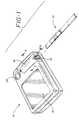
- Figure 1illustrates in exploded, perspective view, a strip 10 for applying a sample thereon and for inserting such sample laden strip 10 into an optical reading apparatus 12.
- the embodiments of the strip 10 and apparatus 12will generally be described hereinafter in terms of detection and quantification of glucose but it will be understood by those skilled in the art that the teachings herein are not limited to glucose determinations, and instead may be applied to other analyte determinations.
- the strip 10, the apparatus 12 and their respective component partsshall all be described as being in the orientation shown in the drawings and terms such as “the bottom” and “the top” shall be employed consistent with such orientation. It will be appreciated, however, that this method of description is merely convenient and that in no way is the invention restricted to such orientation and, in fact, the strip and strip holder may be rotated through any angle relative to the apparatus and the teachings herein shall still apply.
- the strip 10is adapted to be inserted longitudinally, into an opening 14 of a strip holder 16 carried on apparatus 12.
- Strip holder 16shown in more detail in Figures 2 and 3, is preferably removable from apparatus 12 for cleaning.
- the apparatus 12is provided on its visible surface with a screen 18 on which messages, instructions, error warnings, and most importantly, results may be displayed by means such as liquid crystal displays as are well known in the art. Such information may be conveyed by letters, words, numbers or icons.
- apparatus 12is provided with a power switch for activating the apparatus, preferably with batteries and such power switch is shown as push button 20 on the drawings.
- the strip holder 16is comprised of an upper guide 22 and a lower guide 24 which together form a channel or strip passageway 26 into which the strip is inserted via opening 14.
- the extent of insertion of the stripis determined by strip impeding wall 31, which, in accordance with the teachings of this invention is designed to mate with the shape of the insertion end of the strip when the strip is properly inserted and to interfere with the insertion end of the strip when the strip is inserted upside down.
- the passageway 26is canted at an angle with respect to the plane of the bottom 28 of the apparatus 12, so as to facilitate the insertion of strip 10 into the apparatus when the apparatus is sitting on a flat surface.
- the lower guide 24is provided with an aperture 30 through which the bottom major surface 11 of the strip 10 can be “seen” by the optics located below lower guide 24.
- the aperture 30is positioned along the lower guide 24 so as to "see” the bottom surface of a reaction zone of strip 10 when the strip 10 is fully inserted into passageway 26.
- Optic block 32contains a light emitting diode (LED) 36 capable of directing light through aperture 30, upon a surface such as the lower surface 11 of the strip.
- the light emitting diodeis preferably one which emits light of essentially a uniform wavelength in rapid bursts for a period of time, each time it is activated. For the purposes of glucose determination it has been found preferable to employ two such LED's, each emitting light at a different wavelength and preferably at 660 and 940 nanometers (LED 660 and LED 940, respectively).
- the optic block 32also comprises a photodetector 38, a device capable of intercepting light reflected from the surface upon which the LED's focus and converting such light into a measurable voltage.
- bias means 40which is adapted to be biased toward the upper surface 42 of the lower guide in the area of the aperture 30 so as to ensure that the portion of the strip 10 lying over the aperture 30 is flat and presents an optically consistent surface to the optics.
- bias means 40comprises an elastomeric membrane having, on its surface opposing the aperture, a ring-like projecting gasket 44 which is adapted to bear against the strip when in place and hold the strip flat to the aperture.
- a colored targetpreferably gray, hereinafter referred to as the "gray target” 45.
- the gray target 45presents to the optics a surface for assuring the correct calibration of the apparatus before the strip is inserted. Additionally, it is the gray target that is "seen” by the optics once the apparatus is turned on and before a strip is inserted.
- the bias means 40may take forms other than that of an elastomeric membrane.
- a leaf springcan be used as such bias means.
- alternative bias meansare described and include a particularly useful means in which the passageway 26 is designed in a serpentine configuration which, in combination with a strip having spring properties, serves to function as a bias means.
- Such a passagewayis illustrated in Figure 15 wherein upper guide 22 and lower guide 24 are shown. TABLE 1 below recites preferred dimensions for the angles, distances and radii; all based on the x,y coordinates shown in the Figure.
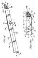
- FIG. 4illustrated therein is a perspective view of the bottom major surface 43 of a strip 46 embodying the teachings of this invention.
- the strip 46comprises an elongate and generally rectangular support 47 onto which is attached a test pad 48 containing reactants and provided with an overlying transport medium 50.
- a test pad 48containing reactants and provided with an overlying transport medium 50.
- the sampleis to be applied to the top surface of the transport medium 50 overlying the test pad 48.
- a portion of the samplepenetrates through the test pad and any glucose present reacts with the reactants therein to produce a color change which is visible on the bottom surface of the test pad.
- a support aperture 52is provided through the support for aligning with aperture 30 in the lower guide of the apparatus when the strip is fully inserted therein, so that a portion of the bottom of the surface of the test pad will be visible to the optics of the apparatus (such portion hereinafter, the reaction zone).
- the transport medium 50comprises pores which draw the sample therethrough by capillary action.
- the transport mediummay be composed of natural materials such as cotton or paper, as well as such synthetic materials as polyesters, polyamides, polyethylene and the like.
- the transport mediumhas pores having an effective diameter in the range of about 20 microns to about 350 microns, preferably about 50 to about 150 microns, e.g., 100 microns.
- the transport mediumis generally hydrophilic or may be rendered hydrophilic by treatment with surfactants compatible with red blood cells.
- One such compatible surfactantis MAPHOSTM 66 sold by Mazer Chemical, a division of PPG Industries Inc. Chemicals of Gurnee, Illinois.
- the transport mediumis capable of absorbing blood samples of up to about 20 to about 40 microliters e.g., 30 microliters.
- the transport mediummay be, for example, a filter paper or sintered plastic material, such as those porous polyethylene materials commonly available from the Porex Corp. of Fairburn, Georgia.
- the transport mediumis generally fabricated to have a thickness of about 0.022 inch, with about 0.64 cm (0.25) inch width and about 2.5 cm (1.0 inch) length.
- the transport mediumis treated with a red blood cell compatible surfactant solution. Since only about 3 to about 5 microliters of blood are required to saturate the testing pad, the transport medium will preferably possess a small void volume in order not to require large volumes of blood. Excess blood applied to the reagent strip is absorbed and held in the portion of the transport medium which extends beyond the test pad.
- test padis a hydrophilic porous matrix to which reagents may be covalently or non-covalently bound.
- suitable materialinclude polyamides, which are conveniently condensation polymers of monomers of from 4 to 8 carbon atoms, where the monomers are lactams or combinations of diamines and di-carboxylic acids, polysulfones, polyesters, polyethylene, and cellulose based membranes. Other polymeric compositions may also be used.
- the polymer compositionsmay be modified to introduce other functional groups so as to provide for charged structures, so that the surfaces may be neutral, positive, or negative, as well as neutral, basic, or acidic.
- the material of choiceis a hydrophilic, anisotropic polysulfone membrane having pores varying in size from large to small through the thickness of the matrix.
- the preferred matrixis obtained from the Memtec America Corporation of Maryland and has an average pore size ranging from 0.34 to 0.4 micrometers e.g., 0.37 and a thickness of from about 125 to about 140 micrometers e.g., 130 micrometers.
- the ratio of the average diameter of the large to the small poresis about 100.
- the transport medium 50is attached to the test pad 48 by an adhesive layer (not shown).
- Suitable adhesives for this purposeincluding acrylic, rubber, and ethylene vinyl acetate (EVA) based formulations.
- EVAethylene vinyl acetate
- a hot melt adhesivesuch as those known in the art, is preferred.
- the adhesivemay be placed in continuous stripes located only near the perimeter of the test pad, leaving a central portion of the receiving surface of the test pad substantially unobstructed.
- the transport layerwhen the transport layer is composed of a material that fuses at industrially practical temperatures, the transport layer may be attached directly to the test pad by an application of heat and pressure. The transport layer is heated until it begins to melt and then pressed against the testing pad and cooled. Direct attachment of the transport layer to the testing pad by fusion obviates any need for a distinct adhesive layer.
- the adhesive layerconnects the transport medium to the sample receiving surface of the test pad.
- the transport mediumis adapted to accept a whole blood sample and transport a detectable portion of the sample to the receiving surface by capillary action.
- the transport mediumpreferably extends past one or more ends of the test pad so as to form a reservoir for holding excess amounts of blood sample which may be present during actual use. It is usually more desirable to retain such excess amounts of the blood sample in the transport medium, rather than allowing the excess to drip upon the user or upon the viewing means in an uncontrolled fashion. Accordingly, it is preferred that the transport medium be capable of holding from about 20 to about 40 microliters of blood, preferably about 30 microliters of blood and of passing from about 3 to about 5 microliters of blood to the test pad.
- the test padis impregnated with a color forming reagent system specific to an analyte.
- Typical analytesare glucose, cholesterol, urea, and many others which will readily occur to those skilled in the art.
- the color forming reagent systemincludes an enzyme which selectively catalyzes a primary reaction with the analyte of interest.
- a product of the primary reactionmay be a dye which undergoes a change in color that is detectable at the reaction zone.
- the product of the primary reactionmay be an intermediate which undergoes another reaction, preferably also enzyme catalyzed, and participates in a secondary reaction which, directly or indirectly, causes a dye to undergo a change in color which is detectable at the reaction zone.
- An exemplary color-forming reagent systemis the system which is specific to glucose and contains glucose oxidase, a peroxidase, and an oxidizable dye.
- Glucose oxidaseis an enzyme, usually obtained from Aspergillus Niger or Penicillium, that reacts with glucose and oxygen to produce gluconolactone and hydrogen peroxide.
- the hydrogen peroxide so producedcatalyzed by a peroxidase enzyme such as horseradish peroxidase, oxidizes a dye.
- the resulting chromophore(the oxidized dye) exhibits a color that may be observed at the reaction zone.
- oxidizable dyesare known in the art including, for example, those set out in U.S. Patent 5,304,468 incorporated herein by reference.
- One particularly useful oxidizable dyeis the 3-methyl-2 benzothiazolinone hydrazone hydrochloride/8-anilino 1-naphthalenesulfonate dye couple (MBTH/ANS couple) described in copending U.S. patent application Serial No. 245,940, filed May 19, 1994 (LFS 30).
- MBTH/ANS couple3-methyl-2 benzothiazolinone hydrazone hydrochloride/8-anilino 1-naphthalenesulfonate dye couple
- a dye couple of choiceis a derivative of MBTH, meta[3-methyl 2-benzothiazolinone hydrazone] N-sulfonyl benzenesulfonate monosodium coupled with ANS. This combination is described in detail in U.S. Patent Application Serial No. 08/302,575; PCT/US95/12091 incorporated hereby by reference.
- the support 47may be of a material having the properties of being sufficiently rigid to be inserted into the apparatus without undue bending or kinking.
- such supportis comprised of materials such as polyolefins (e.g., polyethylene or polypropylene), polystyrene or polyesters.
- a preferred materialis the polyester available from the Imperial Chemical Industries, Ltd. of the United Kingdom and sold by them under the trademark "Melinex 329" having a thickness of about .036cm (0.014 inches).
- the bottom surface of the stripi.e., the surface to be inserted in face-to-face relationship with the aperture 30 of the lower guide of the apparatus and hence the surface "seen” by the optics of the apparatus
- a reaction zone 54comprising the portion of the test pad 48 visible through the support aperture 52.
- the reaction zone 54is longitudinally placed between the leading insertion edge 56 of the strip (leading with respect to insertion into the apparatus) and the opposite trailing edge 61.
- the reaction zonein order to get a proper reading of the reaction zone by the optics of the apparatus, the reaction zone must be in proper alignment with the aperture 30 in the passageway; i.e., the strip must be fully inserted into the passageway 26 right side up so that the reaction zone is in face to face relationship with aperture 30.
- the extreme portion of the bottom surface at the insertion end of the stripis provided with apparatus-detectable means 58 for cooperating with detecting means located at the corresponding end of the passageway of the apparatus.
- the correct positioning of the stripis assured by combining the apparatus-detectable means and its complimentary detection means in the apparatus (hereinafter collectively “detection system") with the feature of an asymmetrical strip.
- the detection systemmay be any of several which will occur to those skilled in the art based on the teachings herein. It has been discovered that a particularly useful combination is where the apparatus-detectable means 58 comprises a material which is electrically conductive.
- the detection means in the passageway of the apparatusmay then comprise two electrical contacts and associated circuitry, the electrical contacts being positioned in the passageway so that the detectable means will overly these contacts when the strip is fully inserted and close the circuit, the closing of which can be monitored by the apparatus.
- the detectable means having the above-described electrical conduction propertiescan be comprised of any material capable of conducting such as metallic or carbon based conductive inks or blends of conductive/resistive materials as well as conductive polymers (e.g., polyaniline, polypyrrole, polyacetylene, or polythiophene conductive polymers doped with a metal, semi-conductor (e.g.
- the materialmay be screen printed, flexographically applied, rotogravured, painted, laminated, layered, sputtered, vapor deposited, or even insert molded onto the strip. Since the strip is preferably a polymeric film, the material may be incorporated into the starting polymer of the strip itself or impregnated therein at some point in the strip forming process.
- the detection systemcan comprise providing the prescribed region of the strip with a material which has reflective properties in marked contrast to the reflective properties of the passageway when the strip is not present (i.e., the reflectance of the empty passageway).
- the end of the passagewaymay be provided with a set of optics; i.e., a light source such as a light emitting diode (LED) in combination with a reflected light detector such as those described herein for measuring the reflection of the reaction zone of the strip.
- a light sourcesuch as a light emitting diode (LED)
- a reflected light detectorsuch as those described herein for measuring the reflection of the reaction zone of the strip.
- the desired contrasting reflectance of the detectable meansmay be achieved on a strip of this invention by any number of ways as will occur to one skilled in the art.
- the supportmay have laminated to it, in the desired region, a layer having the requisite reflectance.
- the material comprising the supportmay have incorporated therein a coloring material imparting the proper reflectance to the region comprising the detectable means.
- the coloring materialmay be printed or painted onto the appropriate region.
- the method chosen for accomplishing the contrasting reflectance values between the detectable means of an inserted strip and the passageway in the absence of the stripis not critical. It is, however, important that at least a minimal contrast between these two reflectance values be exhibited to the detection means of the apparatus. Accordingly, the lower reflectance value should be no more than 0.9 times the higher reflectance value and, preferably, no more than 0.5 times.
- the detectable means 58are optimally located with respect to the reaction zone 54.
- the portion 54 of the reaction zone readable by the apparatuscomprises a centerpoint 53, centrally located on the longitudinal centerline A-A.
- the detectable means 58are located within the area 55, which area 55 is defined by two parallel lines, L 1 and L 2 , at an angle X with the longitudinal centerline.
- the angle Xhas a value of about 45°.
- the lines L 1 and L 2are spaced apart by a distance of D 1 , which is preferably about 0.81 cm (0.32 inches).
- L 2the line closest to the centerpoint 53, is at a distance D 2 from the centerpoint, the distance being taken along the longitudinal centerline.
- D 2is preferably about 1.32 cm (0.52 inches).
- the strip with apparatus detectable meansis further provided with the feature of asymmetry to assure proper insertion.
- this asymmetryrefers to providing that the extreme portion of the strip at the insertion end is given an asymmetrical shape in the sense that there is no line symmetry about the longitudinal centerline, A-A in Figure 4.
- this insertion endcomprises a region wherein, at a given point (e.g., point a), on the longitudinal center line A-A, the normal distance to a first longitudinal edge 49 (distance a-b) is less than the normal distance to the second edge 51 (distance a-c).
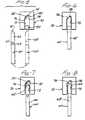
- FIG. 5Also shown in Figure 5 is the complementing portion of an apparatus 70 wherein the passageway 72 at its end 74 contains two contacts 76, 78 (with associated circuitry not shown) as the detection means.
- Strip 60is provided with the same asymmetry described in connection with Figure 4 and, accordingly, the end of passageway 72 is provided with strip impeding walls 80, 82 which mate with the insertion end of strip 60 when the strip is properly inserted.
- Passageway 72is also provided with optics 84 for reading the reaction zone 63.
- detectable means 62now overlies contacts 76 and 78 closing the electrical circuit.
- the apparatusmay be provided with microprocessing means for recognizing the closing of the electrical circuit and, hence, allowing further reading of the strip to continue.
- FIG. 7illustrated therein is a strip 60 inserted into passageway 72 upside down.
- wall 82interferes with the full insertion of the strip.
- the detectable means 62does not overlie contacts 76 and 78, and the electrical circuit is not closed.
- Microprocessing means provided in the apparatusfail to detect a closed circuit and may then preclude an erroneous reading of the strip. Preferably, such detected error is also reported by microprocessing means to a user readable display.
- a strip 60which, while being inserted right side up, has not been fully inserted.
- the detectable means 62fails to overlie contacts 76 and 78 and, hence, the electrical circuit is not closed.
- microprocessing meanswill preclude an erroneous reading and, preferably, report the same to the user.
- Figures 9-12illustrate another embodiment of the invention. Shown in Figure 9 is a strip 90 exhibiting detectable means 92 and support aperture 94, with the bottom major surface 96 viewed full lined on the left and the top major surface 98 shown in the phantom lined view on the right.
- the detectable means 92comprises a surface having light reflective properties contrasting with those of the passageway of the apparatus when the strip is not present, i.e., detectable means 92 present a light surface in contrast to a dark surface for the walls of the passageway.
- a complementary portion of an apparatus 100wherein the passageway 102 at its end 104 contains a detection means 106 which comprises an LED/light detection combination.
- Strip 90is provided with the asymmetry described above, i.e., a "corner” is cut from the insertion end of the strip. Accordingly, the end of passageway 102 is provided with strip impeding walls 108, 110 and 112 which mate with the insertion end of strip 90 when the strip is properly inserted. Passageway 102 is also provided with optics 114 for reading reaction zone 93.
- strip 90is properly and fully inserted into passageway 102. Accordingly, light detectable means 92 overlies the optics of detection means 106 which detects a highly reflective surface.
- the apparatusmay be provided with microprocessing means for recognizing this detected highly reflective surface and, hence, allowing the further reading of the strip to continue.
- a strip 90inserted into passageway 102 upside down.
- the detectable means 92does not overlie the optics of detection means 106 and no highly reflective surface is detected.
- Microprocessing means provided in the apparatusfail to detect a highly reflective surface and may then preclude an erroneous reading of the strip and report the error to the user, using an apparatus display.
- a strip 90which, while being inserted right side up, has not been fully inserted.
- the detectable means 92fail to overlie the optics of the detection means 106 and, hence, no highly reflective surface is detected.
- microprocessing meanswill preclude an erroneous reading and preferably report the same error to the user.
- the detectable meanswas chosen to be highly reflective and was coupled with a dark passageway.
- the detectable meansis dark and a light target, for example, is provided in the passageway.
- the microprocessorwould be programmed accordingly.
- FIG. 13illustrates the operation of a detectable means of the kind employing surface reflectance as the monitored characteristic and detection means in the passageway of a complementary apparatus employing a transistor switch coupled with circuitry.
- Figure 13illustrates the strip 130 having a highly reflectance surface as the detectable means 132.
- Surface 134represents the low reflective surface "seen" by detection means 136 in the absence of the strip in the passageway of the apparatus.
- Detection means 136comprises an LED emitting light symbolized by arrow 138 and light detection means for detecting reflected light, symbolized by arrow 140.
- Detection means 136also comprises a switch 142 containing transistors 144, 146, which when energized by observing reflected light 140 conduct and cause a current (shown as "I") to flow.
- Detection means 136also comprise an application specific integrated circuit (ASIC) 148 comprising a low voltage power source and a node P, at which voltage is monitored.
- ASICapplication specific integrated circuit
- detectable means 132may be of a low reflectance surface and surface 134 may be of high reflectance. Accordingly, when the apparatus is turned on and before the strip is inserted, the switch is energized by receiving substantial reflected light. Once the strip is properly inserted, such reception ceases and current abates. Accordingly, the microprocessor may be programmed to only permit further reading of the strip upon such abatement of the current.
Landscapes
- Health & Medical Sciences (AREA)
- Life Sciences & Earth Sciences (AREA)
- Immunology (AREA)
- Molecular Biology (AREA)
- Chemical & Material Sciences (AREA)
- Engineering & Computer Science (AREA)
- Hematology (AREA)
- Biomedical Technology (AREA)
- Physics & Mathematics (AREA)
- General Health & Medical Sciences (AREA)
- Pathology (AREA)
- Biochemistry (AREA)
- Analytical Chemistry (AREA)
- Urology & Nephrology (AREA)
- General Physics & Mathematics (AREA)
- Microbiology (AREA)
- Cell Biology (AREA)
- Biotechnology (AREA)
- Food Science & Technology (AREA)
- Medicinal Chemistry (AREA)
- Investigating Or Analysing Biological Materials (AREA)
- Investigating Or Analysing Materials By The Use Of Chemical Reactions (AREA)
- Automatic Analysis And Handling Materials Therefor (AREA)
- Measuring Or Testing Involving Enzymes Or Micro-Organisms (AREA)
Abstract
Description
| DIMENSIONS FOR FIGURE 15 | ||
| ANGLES (Degrees) | ||
| A | 26 | |
| B | 17 | |
| C | 9 | |
| DISTANCES -cm (Inches) | ||
| L1 | 1.43 (0.562) | |
| L2 | 1.19 (0.467) | |
| L3 | 0.47 (0.184) | |
| L4 | 0.03 (0.013) | |
| CURVATURE | ||
| RADIUS -cm (Inches) | CENTER (X,Y In) | |
| R1 | 0.5 (0.2) | 0.207, 0.179 |
| R2 | 0.88 (0.347) | 0.391, 0.300 |
| R3 | 0.25 (0.100) | 0.417, 0.006 |
| R4 | 6.69 (2.635) | 0.412, 2.603 |
Claims (9)
- A longitudinally extending test strip (46) fordetermining the presence or quantity of an analyte in aliquid by inserting said test strip into a passageway (26) ofa reading apparatus (12);said test strip having first and second majorsurfaces, and an insertion end (56) for leading the insertionof the strip into said passageway and an opposite trailingend (61);said first major surface having, positionedbetween said insertion end and said trailing end, areaction zone (54), a portion of which is readable by theapparatus when the strip is fully inserted into saidpassageway;said reaction zone having the property ofproducing an apparatus readable indication as a functionof the presence or quantity of said analyte in said liquidwhen a sample of said liquid is applied to said strip;the extreme portion of one of said major surfaces, atthe insertion end, having apparatus detectable means (58) forcooperating with detection means at the corresponding endof the passageway; whereby the apparatus can be programmedto determine whether or not the strip has been fullyinserted therein;said extreme portion of said strip at the insertionend being asymmetrical with respect to the longitudinalcenterline of the strip for cooperating with a matingconfiguration for the passageway of the apparatus, whereby said strip cannot be fully inserted when upsidedown.
- The strip of claim 1 wherein said apparatusdetectable means comprises an area having a contrastingreflectance-with respect to the reflectance of the emptypassageway, wherein one of said reflectances is higherthan the other.
- The strip of claim 2 wherein the lowerreflectance value is no more than 0.9 times the higherreflectance value.
- The strip of claim 3 wherein the lowerreflectance value is no more than 0.5 times the higherreflectance value.
- The strip of claim 1 wherein said apparatusdetectable means comprise electrically conductive materialfor cooperating with electrical circuitry detection means(76, 78) in said apparatus.
- The strip of claim 1 wherein said portion of thereaction zone readable by the apparatus comprises acenterpoint (53)centrally located on the longitudinal centerline of the strip; and said detectable means is within anarea defined by two parallel lines at an angle of 45° withthe longitudinal centerline of the strip, said parallellines being spaced apart a distance of 0.81 cm (0.32 inches) wherein thedistance, along the longitudinal centerline of the strip,between the centerpoint and the line of the parallel linesclosest to the centerpoint, is 1.32 cm (0.52 inches).
- An apparatus for determining the presence orquantity of an analyte in a liquid applied to alongitudinally extendina test strip, by employing a teststrip (46) comprising:
first and second major surfaces, an insertion end (56) forleading the insertion of the strip into the apparatus andan opposite trailing end (61); said first major surface having,positioned between said insertion end and said trailingend, a reaction zone (54) readable by the apparatus when thestrip is fully inserted into said apparatus in a firstorientation; said reaction zone having the property ofproducing an apparatus readable indication as a functionof the presence or quantity of said analyte in said liquidwhen a sample of said liquid is applied to said strip;said strip further comprising at the insertion end of oneof said major surfaces, an apparatus detectable means (58), andsaid strip, at the insertion end, being asymmetrical withrespect to the longitudinal centerline of the strip;wherein
the apparatus comprises:a longitudinally extending passageway (26) having an openend (14) for the insertion of the strip and an opposed end (31);said opposed end having a configuration that mateswith the asymmetrical insertion end of the strip when thestrip is inserted into said apparatus in the firstorientation but a configuration that blocks the fullinsertion of the strip when said strip is inserted in asecond orientation;said opposed end having detection means for detectingthe apparatus detectable means at the insertion end ofsaid strip only when said strip is fully inserted intosaid passageway and for producing a signal characteristicof the detection of said apparatus detectable means. - The apparatus of claim 7 wherein the apparatusdetectable means comprise an area having contrasting lightreflectance property with respect to the light reflectanceproperty of the empty passageway and the detection meanscomprises a reflected light detector (106).
- The apparatus of claim 7 wherein the apparatusdetectable means comprises electrically conductivematerial and the detection means comprises electricalcircuitry detection means.
Applications Claiming Priority (3)
| Application Number | Priority Date | Filing Date | Title |
|---|---|---|---|
| US302281 | 1989-01-27 | ||
| US08/302,281US5526120A (en) | 1994-09-08 | 1994-09-08 | Test strip with an asymmetrical end insuring correct insertion for measuring |
| PCT/US1995/012213WO1996007893A1 (en) | 1994-09-08 | 1995-09-07 | Position detectable strip for analyte detection |
Publications (2)
| Publication Number | Publication Date |
|---|---|
| EP0781406A1 EP0781406A1 (en) | 1997-07-02 |
| EP0781406B1true EP0781406B1 (en) | 1998-05-06 |
Family
ID=23167071
Family Applications (1)
| Application Number | Title | Priority Date | Filing Date |
|---|---|---|---|
| EP95933213AExpired - LifetimeEP0781406B1 (en) | 1994-09-08 | 1995-09-07 | Position detectable strip for analyte detection |
Country Status (14)
| Country | Link |
|---|---|
| US (1) | US5526120A (en) |
| EP (1) | EP0781406B1 (en) |
| JP (1) | JP3655924B2 (en) |
| KR (1) | KR100363989B1 (en) |
| CN (1) | CN1103048C (en) |
| AT (1) | ATE165913T1 (en) |
| AU (1) | AU686016B2 (en) |
| CA (1) | CA2199493C (en) |
| DE (1) | DE69502408T2 (en) |
| DK (1) | DK0781406T3 (en) |
| ES (1) | ES2117448T3 (en) |
| MX (1) | MX9701793A (en) |
| NO (1) | NO318994B1 (en) |
| WO (1) | WO1996007893A1 (en) |
Cited By (9)
| Publication number | Priority date | Publication date | Assignee | Title |
|---|---|---|---|---|
| US6338790B1 (en) | 1998-10-08 | 2002-01-15 | Therasense, Inc. | Small volume in vitro analyte sensor with diffusible or non-leachable redox mediator |
| US6458326B1 (en) | 1999-11-24 | 2002-10-01 | Home Diagnostics, Inc. | Protective test strip platform |
| US6525330B2 (en) | 2001-02-28 | 2003-02-25 | Home Diagnostics, Inc. | Method of strip insertion detection |
| US6541266B2 (en) | 2001-02-28 | 2003-04-01 | Home Diagnostics, Inc. | Method for determining concentration of an analyte in a test strip |
| US6562625B2 (en) | 2001-02-28 | 2003-05-13 | Home Diagnostics, Inc. | Distinguishing test types through spectral analysis |
| US6591125B1 (en) | 2000-06-27 | 2003-07-08 | Therasense, Inc. | Small volume in vitro analyte sensor with diffusible or non-leachable redox mediator |
| US6616819B1 (en) | 1999-11-04 | 2003-09-09 | Therasense, Inc. | Small volume in vitro analyte sensor and methods |
| US6654625B1 (en) | 1999-06-18 | 2003-11-25 | Therasense, Inc. | Mass transport limited in vivo analyte sensor |
| US7909984B2 (en) | 1997-02-06 | 2011-03-22 | Abbott Diabetes Care Inc. | Small volume in vitro analyte sensor |
Families Citing this family (209)
| Publication number | Priority date | Publication date | Assignee | Title |
|---|---|---|---|---|
| US4935346A (en)* | 1986-08-13 | 1990-06-19 | Lifescan, Inc. | Minimum procedure system for the determination of analytes |
| US6335203B1 (en)* | 1994-09-08 | 2002-01-01 | Lifescan, Inc. | Optically readable strip for analyte detection having on-strip orientation index |
| US5728352A (en)* | 1994-11-14 | 1998-03-17 | Advanced Care Products | Disposable electronic diagnostic instrument |
| US5738828A (en)* | 1996-01-16 | 1998-04-14 | Umm Electronics Inc. | Apparatus for detecting proper strip insertion into an optical reflectance meter |
| US5776719A (en)* | 1997-07-07 | 1998-07-07 | Mercury Diagnostics, Inc. | Diagnostic compositions and devices utilizing same |
| US5962215A (en) | 1996-04-05 | 1999-10-05 | Mercury Diagnostics, Inc. | Methods for testing the concentration of an analyte in a body fluid |
| US5989845A (en)* | 1996-04-05 | 1999-11-23 | Mercury Diagnostics, Inc. | Diagnostic compositions and devices utilizing same |
| US6040151A (en)* | 1998-03-10 | 2000-03-21 | Mercury Diagnostics, Inc. | Diagnostic compositions and devices utilizing same |
| WO1997041421A1 (en)* | 1996-04-30 | 1997-11-06 | Metrika, Inc. | Method and device for measuring reflected optical radiation |
| EP1579814A3 (en) | 1996-05-17 | 2006-06-14 | Roche Diagnostics Operations, Inc. | Methods and apparatus for sampling and analyzing body fluid |
| US20020010406A1 (en) | 1996-05-17 | 2002-01-24 | Douglas Joel S. | Methods and apparatus for expressing body fluid from an incision |
| US5815259A (en)* | 1996-09-04 | 1998-09-29 | International Business Machines Corporation | Quick change housing |
| DE69626016T2 (en)* | 1996-09-27 | 2004-01-08 | Inverness Medical Switzerland Gmbh | Test kit and devices |
| ES2186003T3 (en)* | 1996-10-30 | 2003-05-01 | Amira Medical | SYNCHRONIZED ANALYZE ANALYSIS SYSTEM. |
| US5948695A (en) | 1997-06-17 | 1999-09-07 | Mercury Diagnostics, Inc. | Device for determination of an analyte in a body fluid |
| USD403975S (en) | 1997-06-17 | 1999-01-12 | Mercury Diagnostics, Inc. | Test strip device |
| US6046051A (en)* | 1997-06-27 | 2000-04-04 | Hemosense, Inc. | Method and device for measuring blood coagulation or lysis by viscosity changes |
| US6071391A (en) | 1997-09-12 | 2000-06-06 | Nok Corporation | Enzyme electrode structure |
| US7407811B2 (en) | 1997-12-22 | 2008-08-05 | Roche Diagnostics Operations, Inc. | System and method for analyte measurement using AC excitation |
| US8071384B2 (en) | 1997-12-22 | 2011-12-06 | Roche Diagnostics Operations, Inc. | Control and calibration solutions and methods for their use |
| US7390667B2 (en) | 1997-12-22 | 2008-06-24 | Roche Diagnostics Operations, Inc. | System and method for analyte measurement using AC phase angle measurements |
| US7494816B2 (en) | 1997-12-22 | 2009-02-24 | Roche Diagnostic Operations, Inc. | System and method for determining a temperature during analyte measurement |
| US6267722B1 (en) | 1998-02-03 | 2001-07-31 | Adeza Biomedical Corporation | Point of care diagnostic systems |
| US6394952B1 (en) | 1998-02-03 | 2002-05-28 | Adeza Biomedical Corporation | Point of care diagnostic systems |
| US6274326B1 (en)* | 1998-02-17 | 2001-08-14 | Umm Electronics, Inc. | Method and apparatus for detecting proper strip insertion into an optical reflectance meter |
| US6391005B1 (en) | 1998-03-30 | 2002-05-21 | Agilent Technologies, Inc. | Apparatus and method for penetration with shaft having a sensor for sensing penetration depth |
| USD434153S (en)* | 1998-04-20 | 2000-11-21 | Adeza Biomedical Corporation | Point of care analyte detector system |
| USD432244S (en)* | 1998-04-20 | 2000-10-17 | Adeza Biomedical Corporation | Device for encasing an assay test strip |
| US8974386B2 (en) | 1998-04-30 | 2015-03-10 | Abbott Diabetes Care Inc. | Analyte monitoring device and methods of use |
| US6949816B2 (en) | 2003-04-21 | 2005-09-27 | Motorola, Inc. | Semiconductor component having first surface area for electrically coupling to a semiconductor chip and second surface area for electrically coupling to a substrate, and method of manufacturing same |
| US8688188B2 (en) | 1998-04-30 | 2014-04-01 | Abbott Diabetes Care Inc. | Analyte monitoring device and methods of use |
| US8346337B2 (en) | 1998-04-30 | 2013-01-01 | Abbott Diabetes Care Inc. | Analyte monitoring device and methods of use |
| US6175752B1 (en) | 1998-04-30 | 2001-01-16 | Therasense, Inc. | Analyte monitoring device and methods of use |
| US8465425B2 (en) | 1998-04-30 | 2013-06-18 | Abbott Diabetes Care Inc. | Analyte monitoring device and methods of use |
| US8480580B2 (en) | 1998-04-30 | 2013-07-09 | Abbott Diabetes Care Inc. | Analyte monitoring device and methods of use |
| US9066695B2 (en) | 1998-04-30 | 2015-06-30 | Abbott Diabetes Care Inc. | Analyte monitoring device and methods of use |
| US7077328B2 (en)* | 1998-07-31 | 2006-07-18 | Abbott Laboratories | Analyte test instrument system including data management system |
| US6554798B1 (en) | 1998-08-18 | 2003-04-29 | Medtronic Minimed, Inc. | External infusion device with remote programming, bolus estimator and/or vibration alarm capabilities |
| US6251260B1 (en) | 1998-08-24 | 2001-06-26 | Therasense, Inc. | Potentiometric sensors for analytic determination |
| US6261522B1 (en)* | 1998-10-13 | 2001-07-17 | Bayer Corporation | Spectrophotometric apparatus with reagent strip detection |
| US20050103624A1 (en) | 1999-10-04 | 2005-05-19 | Bhullar Raghbir S. | Biosensor and method of making |
| EP1172653A4 (en)* | 2000-02-18 | 2003-07-16 | Matsushita Electric Industrial Co Ltd | CONTROL CHIP FOR SENSOR MEASURING INSTRUMENT |
| DE10020445B4 (en)* | 2000-04-26 | 2005-09-29 | Schlagheck Design Gmbh | Blutzuckermeßstreifen |
| US8641644B2 (en) | 2000-11-21 | 2014-02-04 | Sanofi-Aventis Deutschland Gmbh | Blood testing apparatus having a rotatable cartridge with multiple lancing elements and testing means |
| DE10061336A1 (en)* | 2000-12-08 | 2002-06-13 | Roche Diagnostics Gmbh | System for the analysis of sample liquids including a position control unit |
| US6560471B1 (en) | 2001-01-02 | 2003-05-06 | Therasense, Inc. | Analyte monitoring device and methods of use |
| EP1397068A2 (en) | 2001-04-02 | 2004-03-17 | Therasense, Inc. | Blood glucose tracking apparatus and methods |
| US7126682B2 (en) | 2001-04-11 | 2006-10-24 | Rio Grande Medical Technologies, Inc. | Encoded variable filter spectrometer |
| US6862091B2 (en)* | 2001-04-11 | 2005-03-01 | Inlight Solutions, Inc. | Illumination device and method for spectroscopic analysis |
| EP1395185B1 (en) | 2001-06-12 | 2010-10-27 | Pelikan Technologies Inc. | Electric lancet actuator |
| US8337419B2 (en) | 2002-04-19 | 2012-12-25 | Sanofi-Aventis Deutschland Gmbh | Tissue penetration device |
| US7344507B2 (en) | 2002-04-19 | 2008-03-18 | Pelikan Technologies, Inc. | Method and apparatus for lancet actuation |
| US7749174B2 (en) | 2001-06-12 | 2010-07-06 | Pelikan Technologies, Inc. | Method and apparatus for lancet launching device intergrated onto a blood-sampling cartridge |
| US9795747B2 (en) | 2010-06-02 | 2017-10-24 | Sanofi-Aventis Deutschland Gmbh | Methods and apparatus for lancet actuation |
| JP4209767B2 (en) | 2001-06-12 | 2009-01-14 | ペリカン テクノロジーズ インコーポレイテッド | Self-optimized cutting instrument with adaptive means for temporary changes in skin properties |
| US7981056B2 (en) | 2002-04-19 | 2011-07-19 | Pelikan Technologies, Inc. | Methods and apparatus for lancet actuation |
| US7041068B2 (en) | 2001-06-12 | 2006-05-09 | Pelikan Technologies, Inc. | Sampling module device and method |
| US9226699B2 (en) | 2002-04-19 | 2016-01-05 | Sanofi-Aventis Deutschland Gmbh | Body fluid sampling module with a continuous compression tissue interface surface |
| US9427532B2 (en) | 2001-06-12 | 2016-08-30 | Sanofi-Aventis Deutschland Gmbh | Tissue penetration device |
| USD467349S1 (en) | 2001-09-28 | 2002-12-17 | Orasure Technologies, Inc. | Analyzer |
| US6997343B2 (en)* | 2001-11-14 | 2006-02-14 | Hypoguard Limited | Sensor dispensing device |
| US6723500B2 (en)* | 2001-12-05 | 2004-04-20 | Lifescan, Inc. | Test strips having reaction zones and channels defined by a thermally transferred hydrophobic barrier |
| US20030111357A1 (en)* | 2001-12-13 | 2003-06-19 | Black Murdo M. | Test meter calibration |
| US6908008B2 (en) | 2001-12-21 | 2005-06-21 | Lifescan, Inc. | Test device with means for storing and dispensing diagnostic strips |
| US8367013B2 (en)* | 2001-12-24 | 2013-02-05 | Kimberly-Clark Worldwide, Inc. | Reading device, method, and system for conducting lateral flow assays |
| US6872358B2 (en) | 2002-01-16 | 2005-03-29 | Lifescan, Inc. | Test strip dispenser |
| US7042570B2 (en)* | 2002-01-25 | 2006-05-09 | The Regents Of The University Of California | Porous thin film time-varying reflectivity analysis of samples |
| US20030212379A1 (en)* | 2002-02-26 | 2003-11-13 | Bylund Adam David | Systems and methods for remotely controlling medication infusion and analyte monitoring |
| US20030169426A1 (en)* | 2002-03-08 | 2003-09-11 | Peterson Timothy A. | Test member orientation |
| US7491178B2 (en) | 2002-04-19 | 2009-02-17 | Pelikan Technologies, Inc. | Method and apparatus for penetrating tissue |
| US7708701B2 (en) | 2002-04-19 | 2010-05-04 | Pelikan Technologies, Inc. | Method and apparatus for a multi-use body fluid sampling device |
| US7547287B2 (en) | 2002-04-19 | 2009-06-16 | Pelikan Technologies, Inc. | Method and apparatus for penetrating tissue |
| US7232451B2 (en) | 2002-04-19 | 2007-06-19 | Pelikan Technologies, Inc. | Method and apparatus for penetrating tissue |
| US7892183B2 (en) | 2002-04-19 | 2011-02-22 | Pelikan Technologies, Inc. | Method and apparatus for body fluid sampling and analyte sensing |
| US7901362B2 (en) | 2002-04-19 | 2011-03-08 | Pelikan Technologies, Inc. | Method and apparatus for penetrating tissue |
| US9795334B2 (en) | 2002-04-19 | 2017-10-24 | Sanofi-Aventis Deutschland Gmbh | Method and apparatus for penetrating tissue |
| US7229458B2 (en) | 2002-04-19 | 2007-06-12 | Pelikan Technologies, Inc. | Method and apparatus for penetrating tissue |
| US7976476B2 (en) | 2002-04-19 | 2011-07-12 | Pelikan Technologies, Inc. | Device and method for variable speed lancet |
| US8784335B2 (en) | 2002-04-19 | 2014-07-22 | Sanofi-Aventis Deutschland Gmbh | Body fluid sampling device with a capacitive sensor |
| US8579831B2 (en) | 2002-04-19 | 2013-11-12 | Sanofi-Aventis Deutschland Gmbh | Method and apparatus for penetrating tissue |
| US8360992B2 (en) | 2002-04-19 | 2013-01-29 | Sanofi-Aventis Deutschland Gmbh | Method and apparatus for penetrating tissue |
| US8221334B2 (en) | 2002-04-19 | 2012-07-17 | Sanofi-Aventis Deutschland Gmbh | Method and apparatus for penetrating tissue |
| US7297122B2 (en) | 2002-04-19 | 2007-11-20 | Pelikan Technologies, Inc. | Method and apparatus for penetrating tissue |
| US8372016B2 (en) | 2002-04-19 | 2013-02-12 | Sanofi-Aventis Deutschland Gmbh | Method and apparatus for body fluid sampling and analyte sensing |
| US7674232B2 (en) | 2002-04-19 | 2010-03-09 | Pelikan Technologies, Inc. | Method and apparatus for penetrating tissue |
| US7331931B2 (en) | 2002-04-19 | 2008-02-19 | Pelikan Technologies, Inc. | Method and apparatus for penetrating tissue |
| US9248267B2 (en) | 2002-04-19 | 2016-02-02 | Sanofi-Aventis Deustchland Gmbh | Tissue penetration device |
| US9314194B2 (en) | 2002-04-19 | 2016-04-19 | Sanofi-Aventis Deutschland Gmbh | Tissue penetration device |
| US8702624B2 (en) | 2006-09-29 | 2014-04-22 | Sanofi-Aventis Deutschland Gmbh | Analyte measurement device with a single shot actuator |
| US7909778B2 (en) | 2002-04-19 | 2011-03-22 | Pelikan Technologies, Inc. | Method and apparatus for penetrating tissue |
| US8267870B2 (en) | 2002-04-19 | 2012-09-18 | Sanofi-Aventis Deutschland Gmbh | Method and apparatus for body fluid sampling with hybrid actuation |
| US6743635B2 (en)* | 2002-04-25 | 2004-06-01 | Home Diagnostics, Inc. | System and methods for blood glucose sensing |
| US6946299B2 (en)* | 2002-04-25 | 2005-09-20 | Home Diagnostics, Inc. | Systems and methods for blood glucose sensing |
| US6964871B2 (en)* | 2002-04-25 | 2005-11-15 | Home Diagnostics, Inc. | Systems and methods for blood glucose sensing |
| US20080112852A1 (en)* | 2002-04-25 | 2008-05-15 | Neel Gary T | Test Strips and System for Measuring Analyte Levels in a Fluid Sample |
| US20030212344A1 (en)* | 2002-05-09 | 2003-11-13 | Vadim Yuzhakov | Physiological sample collection devices and methods of using the same |
| US7343188B2 (en)* | 2002-05-09 | 2008-03-11 | Lifescan, Inc. | Devices and methods for accessing and analyzing physiological fluid |
| US20030223906A1 (en)* | 2002-06-03 | 2003-12-04 | Mcallister Devin | Test strip container system |
| US6759190B2 (en)* | 2002-06-15 | 2004-07-06 | Acon Laboratories, Inc. | Test strip for detection of analyte and methods of use |
| US7250095B2 (en)* | 2002-07-11 | 2007-07-31 | Hypoguard Limited | Enzyme electrodes and method of manufacture |
| US20040018114A1 (en)* | 2002-07-26 | 2004-01-29 | Chia-Lin Wang | Test strip holder for a reagent test strip |
| US8574895B2 (en) | 2002-12-30 | 2013-11-05 | Sanofi-Aventis Deutschland Gmbh | Method and apparatus using optical techniques to measure analyte levels |
| US7811231B2 (en) | 2002-12-31 | 2010-10-12 | Abbott Diabetes Care Inc. | Continuous glucose monitoring system and methods of use |
| US7264139B2 (en)* | 2003-01-14 | 2007-09-04 | Hypoguard Limited | Sensor dispensing device |
| US7379167B2 (en) | 2003-02-11 | 2008-05-27 | International Technidyne Corporation | Hemoglobin test strip and analysis system |
| US20040163987A1 (en) | 2003-02-25 | 2004-08-26 | John Allen | Automatically opening medical device package and method of manufacture |
| US7587287B2 (en) | 2003-04-04 | 2009-09-08 | Abbott Diabetes Care Inc. | Method and system for transferring analyte test data |
| WO2004092743A1 (en)* | 2003-04-15 | 2004-10-28 | Optiscan Biomedical Corporation | Sample element qualification |
| DE602004028463D1 (en) | 2003-05-30 | 2010-09-16 | Pelikan Technologies Inc | METHOD AND DEVICE FOR INJECTING LIQUID |
| US7850621B2 (en) | 2003-06-06 | 2010-12-14 | Pelikan Technologies, Inc. | Method and apparatus for body fluid sampling and analyte sensing |
| US8066639B2 (en) | 2003-06-10 | 2011-11-29 | Abbott Diabetes Care Inc. | Glucose measuring device for use in personal area network |
| WO2006001797A1 (en) | 2004-06-14 | 2006-01-05 | Pelikan Technologies, Inc. | Low pain penetrating |
| US8148164B2 (en) | 2003-06-20 | 2012-04-03 | Roche Diagnostics Operations, Inc. | System and method for determining the concentration of an analyte in a sample fluid |
| US8679853B2 (en) | 2003-06-20 | 2014-03-25 | Roche Diagnostics Operations, Inc. | Biosensor with laser-sealed capillary space and method of making |
| US7718439B2 (en) | 2003-06-20 | 2010-05-18 | Roche Diagnostics Operations, Inc. | System and method for coding information on a biosensor test strip |
| US8058077B2 (en) | 2003-06-20 | 2011-11-15 | Roche Diagnostics Operations, Inc. | Method for coding information on a biosensor test strip |
| US7488601B2 (en) | 2003-06-20 | 2009-02-10 | Roche Diagnostic Operations, Inc. | System and method for determining an abused sensor during analyte measurement |
| US7645421B2 (en) | 2003-06-20 | 2010-01-12 | Roche Diagnostics Operations, Inc. | System and method for coding information on a biosensor test strip |
| US7645373B2 (en) | 2003-06-20 | 2010-01-12 | Roche Diagnostic Operations, Inc. | System and method for coding information on a biosensor test strip |
| US7604721B2 (en) | 2003-06-20 | 2009-10-20 | Roche Diagnostics Operations, Inc. | System and method for coding information on a biosensor test strip |
| JP4447009B2 (en) | 2003-06-20 | 2010-04-07 | エフ ホフマン−ラ ロッシュ アクチェン ゲゼルシャフト | Test strip with slot vent opening |
| US8071030B2 (en) | 2003-06-20 | 2011-12-06 | Roche Diagnostics Operations, Inc. | Test strip with flared sample receiving chamber |
| US7452457B2 (en) | 2003-06-20 | 2008-11-18 | Roche Diagnostics Operations, Inc. | System and method for analyte measurement using dose sufficiency electrodes |
| US8206565B2 (en) | 2003-06-20 | 2012-06-26 | Roche Diagnostics Operation, Inc. | System and method for coding information on a biosensor test strip |
| US7597793B2 (en) | 2003-06-20 | 2009-10-06 | Roche Operations Ltd. | System and method for analyte measurement employing maximum dosing time delay |
| DE10338446A1 (en)* | 2003-08-21 | 2005-03-31 | Roche Diagnostics Gmbh | Positioning device for a test element |
| US7920906B2 (en) | 2005-03-10 | 2011-04-05 | Dexcom, Inc. | System and methods for processing analyte sensor data for sensor calibration |
| US8282576B2 (en) | 2003-09-29 | 2012-10-09 | Sanofi-Aventis Deutschland Gmbh | Method and apparatus for an improved sample capture device |
| EP1680014A4 (en) | 2003-10-14 | 2009-01-21 | Pelikan Technologies Inc | METHOD AND DEVICE FOR A VARIABLE USER INTERFACE |
| SG179411A1 (en)* | 2003-11-06 | 2012-04-27 | Lifescan Inc | Drug delivery pen with event notification means |
| US8668656B2 (en) | 2003-12-31 | 2014-03-11 | Sanofi-Aventis Deutschland Gmbh | Method and apparatus for improving fluidic flow and sample capture |
| US7822454B1 (en) | 2005-01-03 | 2010-10-26 | Pelikan Technologies, Inc. | Fluid sampling device with improved analyte detecting member configuration |
| US20050150763A1 (en)* | 2004-01-09 | 2005-07-14 | Butters Colin W. | Biosensor and method of manufacture |
| US20060165557A1 (en)* | 2004-01-23 | 2006-07-27 | Arkray , Inc. | Specimen analyzing tool |
| EP1713926B1 (en) | 2004-02-06 | 2012-08-01 | Bayer HealthCare, LLC | Oxidizable species as an internal reference for biosensors and method of use |
| WO2005089103A2 (en) | 2004-02-17 | 2005-09-29 | Therasense, Inc. | Method and system for providing data communication in continuous glucose monitoring and management system |
| US20070207554A1 (en)* | 2004-02-26 | 2007-09-06 | Lin Alex C C | Medical System and Method for Determining Parameters |
| US7488450B2 (en)* | 2004-03-04 | 2009-02-10 | Beckman Coulter, Inc. | Analyte collection and detection devices |
| WO2006011062A2 (en) | 2004-05-20 | 2006-02-02 | Albatros Technologies Gmbh & Co. Kg | Printable hydrogel for biosensors |
| WO2005120365A1 (en) | 2004-06-03 | 2005-12-22 | Pelikan Technologies, Inc. | Method and apparatus for a fluid sampling device |
| US9775553B2 (en) | 2004-06-03 | 2017-10-03 | Sanofi-Aventis Deutschland Gmbh | Method and apparatus for a fluid sampling device |
| US7556723B2 (en) | 2004-06-18 | 2009-07-07 | Roche Diagnostics Operations, Inc. | Electrode design for biosensor |
| US7569126B2 (en) | 2004-06-18 | 2009-08-04 | Roche Diagnostics Operations, Inc. | System and method for quality assurance of a biosensor test strip |
| US8886272B2 (en) | 2004-07-13 | 2014-11-11 | Dexcom, Inc. | Analyte sensor |
| US7654956B2 (en) | 2004-07-13 | 2010-02-02 | Dexcom, Inc. | Transcutaneous analyte sensor |
| US8652831B2 (en) | 2004-12-30 | 2014-02-18 | Sanofi-Aventis Deutschland Gmbh | Method and apparatus for analyte measurement test time |
| US8112240B2 (en) | 2005-04-29 | 2012-02-07 | Abbott Diabetes Care Inc. | Method and apparatus for providing leak detection in data monitoring and management systems |
| JP5385607B2 (en) | 2005-07-20 | 2014-01-08 | バイエル・ヘルスケア・エルエルシー | Gated current measuring instrument |
| KR101577176B1 (en) | 2005-09-30 | 2015-12-14 | 바이엘 헬스케어 엘엘씨 | Gated voltammetry analyte determination |
| US7766829B2 (en) | 2005-11-04 | 2010-08-03 | Abbott Diabetes Care Inc. | Method and system for providing basal profile modification in analyte monitoring and management systems |
| US20070188736A1 (en)* | 2006-02-16 | 2007-08-16 | Fouquet Julie E | Obtaining measurement and baseline signals for evaluating assay test strips |
| ES2871822T3 (en) | 2006-02-22 | 2021-11-02 | Dexcom Inc | Analyte sensor |
| US7885698B2 (en) | 2006-02-28 | 2011-02-08 | Abbott Diabetes Care Inc. | Method and system for providing continuous calibration of implantable analyte sensors |
| EP4218548A1 (en) | 2006-03-09 | 2023-08-02 | Dexcom, Inc. | Systems and methods for processing analyte sensor data |
| WO2007102842A2 (en) | 2006-03-09 | 2007-09-13 | Dexcom, Inc. | Systems and methods for processing analyte sensor data |
| US7620438B2 (en) | 2006-03-31 | 2009-11-17 | Abbott Diabetes Care Inc. | Method and system for powering an electronic device |
| US8226891B2 (en) | 2006-03-31 | 2012-07-24 | Abbott Diabetes Care Inc. | Analyte monitoring devices and methods therefor |
| US20070267513A1 (en)* | 2006-05-17 | 2007-11-22 | Taylor William A | Low profile fountain or water display |
| WO2007143225A2 (en) | 2006-06-07 | 2007-12-13 | Abbott Diabetes Care, Inc. | Analyte monitoring system and method |
| US7740580B2 (en)* | 2006-10-31 | 2010-06-22 | Abbott Diabetes Care Inc. | Analyte monitoring |
| US8158081B2 (en)* | 2006-10-31 | 2012-04-17 | Abbott Diabetes Care Inc. | Analyte monitoring devices |
| WO2008082987A2 (en)* | 2006-12-26 | 2008-07-10 | Abbott Diabetes Care Inc | Analyte meter protectors and methods |
| US8732188B2 (en) | 2007-02-18 | 2014-05-20 | Abbott Diabetes Care Inc. | Method and system for providing contextual based medication dosage determination |
| US8930203B2 (en) | 2007-02-18 | 2015-01-06 | Abbott Diabetes Care Inc. | Multi-function analyte test device and methods therefor |
| US8123686B2 (en) | 2007-03-01 | 2012-02-28 | Abbott Diabetes Care Inc. | Method and apparatus for providing rolling data in communication systems |
| US7928850B2 (en) | 2007-05-08 | 2011-04-19 | Abbott Diabetes Care Inc. | Analyte monitoring system and methods |
| US8461985B2 (en) | 2007-05-08 | 2013-06-11 | Abbott Diabetes Care Inc. | Analyte monitoring system and methods |
| US8665091B2 (en) | 2007-05-08 | 2014-03-04 | Abbott Diabetes Care Inc. | Method and device for determining elapsed sensor life |
| US8456301B2 (en) | 2007-05-08 | 2013-06-04 | Abbott Diabetes Care Inc. | Analyte monitoring system and methods |
| US20080297169A1 (en)* | 2007-05-31 | 2008-12-04 | Greenquist Alfred C | Particle Fraction Determination of A Sample |
| KR20150108949A (en) | 2007-10-10 | 2015-09-30 | 아가매트릭스, 인코포레이티드 | Identification method for electro chemical test strips |
| WO2009076302A1 (en) | 2007-12-10 | 2009-06-18 | Bayer Healthcare Llc | Control markers for auto-detection of control solution and methods of use |
| GB0725234D0 (en)* | 2007-12-24 | 2008-02-06 | Oxtex Ltd | Electrochemical assays |
| US11730407B2 (en) | 2008-03-28 | 2023-08-22 | Dexcom, Inc. | Polymer membranes for continuous analyte sensors |
| EP2265324B1 (en) | 2008-04-11 | 2015-01-28 | Sanofi-Aventis Deutschland GmbH | Integrated analyte measurement system |
| KR20140117698A (en)* | 2008-07-07 | 2014-10-07 | 아가매트릭스, 인코포레이티드 | Integrated blood glucose measurement device |
| US7896703B2 (en)* | 2008-07-17 | 2011-03-01 | Abbott Diabetes Care Inc. | Strip connectors for measurement devices |
| US8103456B2 (en) | 2009-01-29 | 2012-01-24 | Abbott Diabetes Care Inc. | Method and device for early signal attenuation detection using blood glucose measurements |
| US9375169B2 (en) | 2009-01-30 | 2016-06-28 | Sanofi-Aventis Deutschland Gmbh | Cam drive for managing disposable penetrating member actions with a single motor and motor and control system |
| US20100213057A1 (en) | 2009-02-26 | 2010-08-26 | Benjamin Feldman | Self-Powered Analyte Sensor |
| US20100249965A1 (en)* | 2009-03-31 | 2010-09-30 | Agamatrix, Inc. | Integrated Blood Glucose Measurement Device |
| WO2010127050A1 (en) | 2009-04-28 | 2010-11-04 | Abbott Diabetes Care Inc. | Error detection in critical repeating data in a wireless sensor system |
| WO2010138856A1 (en) | 2009-05-29 | 2010-12-02 | Abbott Diabetes Care Inc. | Medical device antenna systems having external antenna configurations |
| US9314195B2 (en) | 2009-08-31 | 2016-04-19 | Abbott Diabetes Care Inc. | Analyte signal processing device and methods |
| US8993331B2 (en) | 2009-08-31 | 2015-03-31 | Abbott Diabetes Care Inc. | Analyte monitoring system and methods for managing power and noise |
| US9320461B2 (en) | 2009-09-29 | 2016-04-26 | Abbott Diabetes Care Inc. | Method and apparatus for providing notification function in analyte monitoring systems |
| USD652750S1 (en)* | 2010-01-25 | 2012-01-24 | X-Rite, Inc. | Color verification card |
| USD659038S1 (en)* | 2010-02-03 | 2012-05-08 | Hach Lange Gmbh | Portable turbidimeter |
| US8965476B2 (en) | 2010-04-16 | 2015-02-24 | Sanofi-Aventis Deutschland Gmbh | Tissue penetration device |
| KR101191329B1 (en) | 2010-07-02 | 2012-10-16 | 주식회사 올메디쿠스 | Test strip for analyzing body fluid |
| WO2012058237A1 (en) | 2010-10-26 | 2012-05-03 | Abbott Diabetes Care Inc. | Analyte measurement devices and systems, and components and methods related thereto |
| US20120130646A1 (en)* | 2010-11-19 | 2012-05-24 | Lifescan, Inc. | Analyte testing method and system with high and low analyte trends notification |
| US9713440B2 (en) | 2010-12-08 | 2017-07-25 | Abbott Diabetes Care Inc. | Modular analyte measurement systems, modular components thereof and related methods |
| USD680454S1 (en) | 2011-10-25 | 2013-04-23 | Abbott Diabetes Care Inc. | Analyte meter and strip port |
| WO2013070794A2 (en) | 2011-11-07 | 2013-05-16 | Abbott Diabetes Care Inc. | Analyte monitoring device and methods |
| EP2812675B1 (en)* | 2012-02-06 | 2021-07-07 | The Regents of the University of California | Portable rapid diagnostic test reader |
| US9968306B2 (en) | 2012-09-17 | 2018-05-15 | Abbott Diabetes Care Inc. | Methods and apparatuses for providing adverse condition notification with enhanced wireless communication range in analyte monitoring systems |
| WO2014166987A1 (en)* | 2013-04-09 | 2014-10-16 | Roche Diagnostics Gmbh | Protective covering for a hand-held medical device |
| US11199498B2 (en) | 2013-05-09 | 2021-12-14 | University Of Central Florida Research Foundation, Inc. | Portable spectrometer for the presumptive identification of substances |
| WO2014183026A1 (en)* | 2013-05-09 | 2014-11-13 | University Of Central Florida Research Foundation, Inc. | A portable spectrometer for the presumptive identification of illicit drugs and substances of abuse |
| US9354194B2 (en) | 2013-06-19 | 2016-05-31 | Cilag Gmbh International | Orientation independent meter |
| TW201514861A (en)* | 2013-10-08 | 2015-04-16 | Hui-Qi Gu | Inspection cartridge reading device and reading method thereof |
| CA2926287C (en) | 2013-11-28 | 2020-03-24 | F. Hoffmann-La Roche Ag | Method and device for determining a concentration of an analyte in a bodily fluid |
| WO2015146238A1 (en)* | 2014-03-27 | 2015-10-01 | テルモ株式会社 | Component measuring apparatus |
| CA2950166C (en) | 2014-07-25 | 2023-08-01 | Becton, Dickinson And Company | Analyte test strip assays, and test strips and kits for use in practicing the same |
| CN105911286B (en)* | 2016-05-20 | 2017-09-15 | 深圳市家康科技有限公司 | A kind of blood glucose meter test paper |
| US10309920B2 (en) | 2016-05-26 | 2019-06-04 | Trividia Health, Inc. | Gating system and method for biosensor test strips |
| TWI707662B (en)* | 2019-09-12 | 2020-10-21 | 華廣生技股份有限公司 | Physiological sensing apparatus for reading a strip |
| CN113777059B (en)* | 2021-10-19 | 2024-12-03 | 石家庄洹众生物科技有限公司 | An electronic reader device and a detection method |
Family Cites Families (51)
| Publication number | Priority date | Publication date | Assignee | Title |
|---|---|---|---|---|
| NL268685A (en)* | 1960-09-01 | |||
| ES310641A1 (en)* | 1964-03-20 | 1965-07-01 | Boehringer & Soehne Gmbh | PROCEDURE FOR OBTAINING A DIAGNOSTIC MEANS FOR THE RECOGNITION OF THE CONSTITUENTS OF PURE BLOOD |
| US3552928A (en)* | 1967-07-19 | 1971-01-05 | Miles Lab | Whole blood separation means and test system using same |
| US3992158A (en)* | 1973-08-16 | 1976-11-16 | Eastman Kodak Company | Integral analytical element |
| FR2295419A1 (en)* | 1974-12-21 | 1976-07-16 | Kyoto Daiichi Kagaku Kk | REFLECTANCE MEASURING DEVICE AND COMPOSITE TEST PAPER STRUCTURE SUBJECT TO SUCH MEASUREMENT |
| JPS51114985A (en)* | 1975-04-01 | 1976-10-09 | Kyoto Daiichi Kagaku:Kk | Mothod to analyse urine, etc. |
| US4042335A (en)* | 1975-07-23 | 1977-08-16 | Eastman Kodak Company | Integral element for analysis of liquids |
| CA1095819A (en)* | 1977-01-14 | 1981-02-17 | Eastman Kodak Company | Element for analysis of liquids |
| DE2932973A1 (en)* | 1978-08-14 | 1980-02-28 | Fuji Photo Film Co Ltd | INTEGRAL MULTILAYERED MATERIAL FOR CHEMICAL ANALYSIS OF BLOOD |
| US4258001A (en)* | 1978-12-27 | 1981-03-24 | Eastman Kodak Company | Element, structure and method for the analysis or transport of liquids |
| JPS55164356A (en)* | 1979-06-08 | 1980-12-22 | Fuji Photo Film Co Ltd | Multi-layer analysis sheet for liquid sample analysis |
| US4816224A (en)* | 1980-08-05 | 1989-03-28 | Boehringer Mannheim Gmbh | Device for separating plasma or serum from whole blood and analyzing the same |
| GB2090659A (en)* | 1981-01-02 | 1982-07-14 | Instrumentation Labor Inc | Analytical device |
| GB2096314A (en)* | 1981-03-26 | 1982-10-13 | Lre Relais & Elektronik Gmbh | Apparatus for optoelectric evaluation of test paper strips |
| JPS57208997A (en)* | 1981-06-17 | 1982-12-22 | Fuji Photo Film Co Ltd | Liquid analyzing material for oxidase enzyme reaction system |
| DE3133826A1 (en)* | 1981-08-27 | 1983-03-10 | Boehringer Mannheim Gmbh, 6800 Mannheim | ANALYSIS TEST STRIP AND METHOD FOR THE PRODUCTION THEREOF |
| US5095026A (en)* | 1983-02-04 | 1992-03-10 | University Of Iowa Research Foundation | Prodrugs of carbonic anhydrase inhibitors |
| EP0170375B1 (en)* | 1984-06-13 | 1990-05-16 | Unilever Plc | Devices for use in chemical test procedures |
| US4791461A (en)* | 1984-11-27 | 1988-12-13 | Syntex (U.S.A.) Inc. | Portable analyzer |
| JPS61262661A (en)* | 1985-05-16 | 1986-11-20 | Konishiroku Photo Ind Co Ltd | Biochemical analysis unit |
| US4682895A (en)* | 1985-08-06 | 1987-07-28 | Texas A&M University | Fiber optic probe for quantification of colorimetric reactions |
| US4714874A (en)* | 1985-11-12 | 1987-12-22 | Miles Inc. | Test strip identification and instrument calibration |
| EP0253371A1 (en)* | 1986-07-15 | 1988-01-20 | Omron Tateisi Electronics Co. | Chemical level measurement device with easy action cover and single control mode selection capability |
| US5029583A (en)* | 1986-07-22 | 1991-07-09 | Personal Diagnostics, Inc. | Optical analyzer |
| US5059394A (en)* | 1986-08-13 | 1991-10-22 | Lifescan, Inc. | Analytical device for the automated determination of analytes in fluids |
| US4790979A (en)* | 1986-08-29 | 1988-12-13 | Technimed Corporation | Test strip and fixture |
| JPH07117492B2 (en)* | 1987-01-13 | 1995-12-18 | 富士写真フイルム株式会社 | Method for manufacturing chemical analysis slide |
| US4774192A (en)* | 1987-01-28 | 1988-09-27 | Technimed Corporation | A dry reagent delivery system with membrane having porosity gradient |
| DK142388A (en)* | 1987-03-17 | 1988-09-18 | Diagnostic Systems Inc | METHOD AND APPARATUS FOR DETECTING ANALYTES IN FLUIDUM SAMPLES, NAMELY GLUCOSE IN BODY LIQUIDS |
| JPH079069Y2 (en)* | 1987-11-24 | 1995-03-06 | オムロン株式会社 | Reflector for blank value measurement of biochemical measuring instrument |
| US4994238A (en)* | 1988-06-09 | 1991-02-19 | Daffern George M | Constant volume chemical analysis test device |
| US5236940A (en)* | 1988-12-15 | 1993-08-17 | Rhone-Poulenc Sante | Pharmaceutical compositions, 2-benzothiazolamine derivatives, and their preparation |
| US5252293A (en)* | 1989-01-17 | 1993-10-12 | Vladimir Drbal | Analytical slide with porous filter membrane |
| JP2790299B2 (en)* | 1989-02-01 | 1998-08-27 | 保土谷化学工業株式会社 | Penzothiazole derivative |
| US4952893A (en)* | 1989-03-13 | 1990-08-28 | Teradyne, Inc. | Attenuating circuit |
| GB8911462D0 (en)* | 1989-05-18 | 1989-07-05 | Ares Serono Res & Dev Ltd | Devices for use in chemical test procedures |
| DE3921391A1 (en)* | 1989-06-29 | 1991-01-10 | Lre Relais & Elektronik Gmbh | DEVICE FOR REMISSION-PHOTOMETRIC ANALYSIS OF LIQUID SAMPLES |
| US5306623A (en)* | 1989-08-28 | 1994-04-26 | Lifescan, Inc. | Visual blood glucose concentration test strip |
| DE69025110T2 (en)* | 1989-09-08 | 1996-08-08 | Terumo Corp | Test device |
| JPH0395435A (en)* | 1989-09-08 | 1991-04-19 | Terumo Corp | Measuring apparatus |
| AU635314B2 (en)* | 1989-09-08 | 1993-03-18 | Terumo Kabushiki Kaisha | Measuring apparatus |
| DE4035052C2 (en)* | 1989-11-29 | 1995-06-08 | Boehringer Mannheim Gmbh | Test vehicle analyzer |
| DE4015157A1 (en)* | 1990-05-11 | 1991-11-14 | Miles Inc | ASYMETRIC SANDWICH MEMBRANES FOR DIAGNOSTIC TEST STRIPS |
| DE4015590A1 (en)* | 1990-05-15 | 1991-11-21 | Boehringer Mannheim Gmbh | TEST CARRIER FOR THE DETERMINATION OF IONS |
| JPH04113268A (en)* | 1990-09-04 | 1992-04-14 | Toto Ltd | Mechanism for preventing bending of specimen for urine analyzer |
| US5167145B1 (en)* | 1990-09-19 | 2000-05-23 | David M Butler | Measurement of blood coagulation time using infrared electromagnetic energy |
| US5174963A (en)* | 1991-01-07 | 1992-12-29 | United Medical Manufacturing Company | Blood glucose reflectance meter including a null prompting means and a device for providing a constant brightness light |
| US5232668A (en)* | 1991-02-27 | 1993-08-03 | Boehringer Mannheim Corporation | Test strip holding and reading mechanism for a meter |
| US5246858A (en)* | 1991-02-27 | 1993-09-21 | Boehringer Mannheim Corporation | Apparatus and method for analyzing a body fluid |
| GR1002549B (en)* | 1992-05-12 | 1997-01-28 | Lifescan Inc. | Fluid conducting test strip with Transport Medium |
| WO1994018559A1 (en)* | 1993-02-11 | 1994-08-18 | Radiometer Medical A/S | Asymmetric membrane sensor |
- 1994
- 1994-09-08USUS08/302,281patent/US5526120A/ennot_activeExpired - Lifetime
- 1995
- 1995-09-07MXMX9701793Apatent/MX9701793A/enactiveIP Right Grant
- 1995-09-07ESES95933213Tpatent/ES2117448T3/ennot_activeExpired - Lifetime
- 1995-09-07DEDE69502408Tpatent/DE69502408T2/ennot_activeExpired - Lifetime
- 1995-09-07AUAU35965/95Apatent/AU686016B2/ennot_activeExpired
- 1995-09-07ATAT95933213Tpatent/ATE165913T1/enactive
- 1995-09-07WOPCT/US1995/012213patent/WO1996007893A1/enactiveIP Right Grant
- 1995-09-07CNCN95196102Apatent/CN1103048C/ennot_activeExpired - Lifetime
- 1995-09-07EPEP95933213Apatent/EP0781406B1/ennot_activeExpired - Lifetime
- 1995-09-07CACA002199493Apatent/CA2199493C/ennot_activeExpired - Lifetime
- 1995-09-07KRKR1019970701614Apatent/KR100363989B1/ennot_activeExpired - Lifetime
- 1995-09-07JPJP50973396Apatent/JP3655924B2/ennot_activeExpired - Lifetime
- 1995-09-07DKDK95933213Tpatent/DK0781406T3/enactive
- 1997
- 1997-03-05NONO19971009Apatent/NO318994B1/ennot_activeIP Right Cessation
Cited By (66)
| Publication number | Priority date | Publication date | Assignee | Title |
|---|---|---|---|---|
| US7909984B2 (en) | 1997-02-06 | 2011-03-22 | Abbott Diabetes Care Inc. | Small volume in vitro analyte sensor |
| US9234864B2 (en) | 1997-02-06 | 2016-01-12 | Abbott Diabetes Care Inc. | Small volume in vitro analyte sensor |
| US8142643B2 (en) | 1997-02-06 | 2012-03-27 | Abbott Diabetes Care Inc. | Small volume in vitro analyte sensor |
| US8123929B2 (en) | 1997-02-06 | 2012-02-28 | Abbott Diabetes Care Inc. | Small volume in vitro analyte sensor |
| US8118992B2 (en) | 1997-02-06 | 2012-02-21 | Abbott Diabetes Care Inc. | Small volume in vitro analyte sensor |
| US8114270B2 (en) | 1997-02-06 | 2012-02-14 | Abbott Diabetes Care Inc. | Small volume in vitro analyte sensor |
| US8114271B2 (en) | 1997-02-06 | 2012-02-14 | Abbott Diabetes Care Inc. | Small volume in vitro analyte sensor |
| US8105476B2 (en) | 1997-02-06 | 2012-01-31 | Abbott Diabetes Care Inc. | Integrated lancing and measurement device |
| US7988845B2 (en) | 1997-02-06 | 2011-08-02 | Abbott Diabetes Care Inc. | Integrated lancing and measurement device and analyte measuring methods |
| US7225535B2 (en) | 1998-10-08 | 2007-06-05 | Abbott Diabetes Care, Inc. | Method of manufacturing electrochemical sensors |
| US8187895B2 (en) | 1998-10-08 | 2012-05-29 | Abbott Diabetes Care Inc. | Small volume in vitro analyte sensor and methods of making |
| US9341591B2 (en) | 1998-10-08 | 2016-05-17 | Abbott Diabetes Care Inc. | Small volume in vitro analyte sensor |
| US9316609B2 (en) | 1998-10-08 | 2016-04-19 | Abbott Diabetes Care Inc. | Small volume in vitro analyte sensor |
| US9291592B2 (en) | 1998-10-08 | 2016-03-22 | Abbott Diabetes Care Inc. | Small volume in vitro analyte sensor |
| US9234863B2 (en) | 1998-10-08 | 2016-01-12 | Abbott Diabetes Care Inc. | Small volume in vitro analyte sensor |
| US7058437B2 (en) | 1998-10-08 | 2006-06-06 | Therasense, Inc. | Methods of determining concentration of glucose |
| US6338790B1 (en) | 1998-10-08 | 2002-01-15 | Therasense, Inc. | Small volume in vitro analyte sensor with diffusible or non-leachable redox mediator |
| US8701282B2 (en) | 1998-10-08 | 2014-04-22 | Abbott Diabetes Care Inc. | Method for manufacturing a biosensor |
| US7563350B2 (en) | 1998-10-08 | 2009-07-21 | Abbott Diabetes Care Inc. | Small volume in vitro analyte sensor |
| US6618934B1 (en) | 1998-10-08 | 2003-09-16 | Therasense, Inc. | Method of manufacturing small volume in vitro analyte sensor |
| US8650751B2 (en) | 1998-10-08 | 2014-02-18 | Abbott Diabetes Care Inc. | Methods of making small volume in vitro analyte sensors |
| US8449758B2 (en) | 1998-10-08 | 2013-05-28 | Abbott Diabetes Care Inc. | Small volume in vitro analyte sensor and methods of making |
| US8083928B2 (en) | 1998-10-08 | 2011-12-27 | Abbott Diabetes Care Inc. | Small volume in vitro analyte sensor and methods of making |
| US8083929B2 (en) | 1998-10-08 | 2011-12-27 | Abbott Diabetes Care Inc. | Small volume in vitro sensor and methods of making |
| US8083924B2 (en) | 1998-10-08 | 2011-12-27 | Abbott Diabetes Care Inc. | Small volume in vitro analyte sensor and methods of making |
| US8087162B2 (en) | 1998-10-08 | 2012-01-03 | Abbott Diabetes Care Inc. | Methods of making small volume in vitro analyte sensors |
| US8091220B2 (en) | 1998-10-08 | 2012-01-10 | Abbott Diabetes Care Inc. | Methods of making small volume in vitro analyte sensors |
| US6592745B1 (en) | 1998-10-08 | 2003-07-15 | Therasense, Inc. | Method of using a small volume in vitro analyte sensor with diffusible or non-leachable redox mediator |
| US8425743B2 (en) | 1998-10-08 | 2013-04-23 | Abbott Diabetes Care Inc. | Small volume in vitro analyte sensor and methods of making |
| US8425758B2 (en) | 1998-10-08 | 2013-04-23 | Abbott Diabetes Care Inc. | Small volume in vitro analyte sensor and methods of making |
| US8118993B2 (en) | 1998-10-08 | 2012-02-21 | Abbott Diabetes Care Inc. | Small volume in vitro analyte sensor and methods of making |
| US8377378B2 (en) | 1998-10-08 | 2013-02-19 | Abbott Diabetes Care Inc. | Small volume in vitro analyte sensor and methods of making |
| US8372261B2 (en) | 1998-10-08 | 2013-02-12 | Abbott Diabetes Care Inc. | Small volume in vitro analyte sensor and methods of making |
| US6461496B1 (en) | 1998-10-08 | 2002-10-08 | Therasense, Inc. | Small volume in vitro analyte sensor with diffusible or non-leachable redox mediator |
| US8153063B2 (en) | 1998-10-08 | 2012-04-10 | Abbott Diabetes Care Inc. | Small volume in vitro analyte sensor and methods of making |
| US8163164B2 (en) | 1998-10-08 | 2012-04-24 | Abbott Diabetes Care Inc. | Small volume in vitro analyte sensor and methods of making |
| US8182671B2 (en) | 1998-10-08 | 2012-05-22 | Abbott Diabetes Care Inc. | Small volume in vitro analyte sensor and methods of making |
| US8182670B2 (en) | 1998-10-08 | 2012-05-22 | Abbott Diabetes Care Inc. | Small volume in vitro analyte sensor and methods of making |
| US8272125B2 (en) | 1998-10-08 | 2012-09-25 | Abbott Diabetes Care Inc. | Method of manufacturing in vitro analyte sensors |
| US8186044B2 (en) | 1998-10-08 | 2012-05-29 | Abbott Diabetes Care Inc. | Method of manufacturing small volume in vitro analyte sensors |
| US8192611B2 (en) | 1998-10-08 | 2012-06-05 | Abbott Diabetes Care Inc. | Small volume in vitro analyte sensor and methods of making |
| US8211363B2 (en) | 1998-10-08 | 2012-07-03 | Abbott Diabetes Care Inc. | Small volume in vitro analyte sensor and methods of making |
| US8221685B2 (en) | 1998-10-08 | 2012-07-17 | Abbott Diabetes Care Inc. | Small volume in vitro sensor and methods of making |
| US8226815B2 (en) | 1998-10-08 | 2012-07-24 | Abbott Diabetes Care Inc. | Small volume in vitro sensor and methods of making |
| US8262996B2 (en) | 1998-10-08 | 2012-09-11 | Abbott Diabetes Care Inc. | Small volume in vitro sensor and methods of making |
| US8268163B2 (en) | 1998-10-08 | 2012-09-18 | Abbott Diabetes Care Inc. | Small volume in vitro analyte sensor and methods of making |
| US8268144B2 (en) | 1998-10-08 | 2012-09-18 | Abbott Diabetes Care Inc. | Small volume in vitro analyte sensor and methods of making |
| US8273241B2 (en) | 1998-10-08 | 2012-09-25 | Abbott Diabetes Care Inc. | Small volume in vitro analyte sensor and methods of making |
| US6975893B2 (en) | 1999-06-18 | 2005-12-13 | Therasense, Inc. | Mass transport limited in vivo analyte sensor |
| US6654625B1 (en) | 1999-06-18 | 2003-11-25 | Therasense, Inc. | Mass transport limited in vivo analyte sensor |
| US6749740B2 (en) | 1999-11-04 | 2004-06-15 | Therasense, Inc. | Small volume in vitro analyte sensor and methods |
| US6942518B2 (en) | 1999-11-04 | 2005-09-13 | Therasense, Inc. | Small volume in vitro analyte sensor and methods |
| US8066858B2 (en) | 1999-11-04 | 2011-11-29 | Abbott Diabetes Care Inc. | Analyte sensor with insertion monitor, and methods |
| US6616819B1 (en) | 1999-11-04 | 2003-09-09 | Therasense, Inc. | Small volume in vitro analyte sensor and methods |
| US6458326B1 (en) | 1999-11-24 | 2002-10-01 | Home Diagnostics, Inc. | Protective test strip platform |
| US6979571B2 (en) | 1999-11-24 | 2005-12-27 | Home Diagnostics, Inc. | Method of using a protective test strip platform for optical meter apparatus |
| US6591125B1 (en) | 2000-06-27 | 2003-07-08 | Therasense, Inc. | Small volume in vitro analyte sensor with diffusible or non-leachable redox mediator |
| US8795176B2 (en) | 2000-06-27 | 2014-08-05 | Abbott Diabetes Care Inc. | Integrated sample acquisition and analyte measurement device |
| US9017259B2 (en) | 2000-06-27 | 2015-04-28 | Abbott Diabetes Care Inc. | Integrated sample acquisition and analyte measurement device |
| US8532731B2 (en) | 2000-06-27 | 2013-09-10 | Abbott Diabetes Care Inc. | Methods of determining analyte concentration |
| US9271669B2 (en) | 2000-06-27 | 2016-03-01 | Abbott Diabetes Care Inc. | Method for integrated sample acquisition and analyte measurement device |
| US9662057B2 (en) | 2000-06-27 | 2017-05-30 | Abbott Diabetes Care Inc. | Integrated sample acquisition and analyte measurement method |
| US7390665B2 (en) | 2001-02-28 | 2008-06-24 | Gilmour Steven B | Distinguishing test types through spectral analysis |
| US6562625B2 (en) | 2001-02-28 | 2003-05-13 | Home Diagnostics, Inc. | Distinguishing test types through spectral analysis |
| US6541266B2 (en) | 2001-02-28 | 2003-04-01 | Home Diagnostics, Inc. | Method for determining concentration of an analyte in a test strip |
| US6525330B2 (en) | 2001-02-28 | 2003-02-25 | Home Diagnostics, Inc. | Method of strip insertion detection |
Also Published As
| Publication number | Publication date |
|---|---|
| CN1103048C (en) | 2003-03-12 |
| MX9701793A (en) | 1997-06-28 |
| NO318994B1 (en) | 2005-05-30 |
| CN1162994A (en) | 1997-10-22 |
| US5526120A (en) | 1996-06-11 |
| ES2117448T3 (en) | 1998-08-01 |
| WO1996007893A1 (en) | 1996-03-14 |
| JPH10505677A (en) | 1998-06-02 |
| AU3596595A (en) | 1996-03-27 |
| JP3655924B2 (en) | 2005-06-02 |
| AU686016B2 (en) | 1998-01-29 |
| CA2199493C (en) | 2006-11-21 |
| EP0781406A1 (en) | 1997-07-02 |
| DE69502408T2 (en) | 1998-10-22 |
| ATE165913T1 (en) | 1998-05-15 |
| DE69502408D1 (en) | 1998-06-10 |
| CA2199493A1 (en) | 1996-03-14 |
| NO971009L (en) | 1997-04-25 |
| KR970706493A (en) | 1997-11-03 |
| DK0781406T3 (en) | 1999-03-01 |
| NO971009D0 (en) | 1997-03-05 |
| KR100363989B1 (en) | 2003-02-05 |
Similar Documents
| Publication | Publication Date | Title |
|---|---|---|
| EP0781406B1 (en) | Position detectable strip for analyte detection | |
| EP0779983B2 (en) | Optically readable strip for analyte detection having on-strip orientation index | |
| EP0779984B1 (en) | Optically readable strip for analyte detection having on-strip standard | |
| EP0781405B1 (en) | Analyte detector having serpentine strip channel | |
| WO1996007908A9 (en) | Optically readable strip for analyte detection having on-strip standard | |
| MXPA97001793A (en) | Detectable strip as a position for the detection of anali | |
| MXPA97001791A (en) | Strip optically ready for detection of analyts that have indication of orientation on the t | |
| MXPA97001792A (en) | Strip optically ready for detection of analytics that have a normal zone over the mi | |
| RU2298794C2 (en) | Indicator device and system for measuring concentration |
Legal Events
| Date | Code | Title | Description |
|---|---|---|---|
| PUAI | Public reference made under article 153(3) epc to a published international application that has entered the european phase | Free format text:ORIGINAL CODE: 0009012 | |
| 17P | Request for examination filed | Effective date:19970404 | |
| AK | Designated contracting states | Kind code of ref document:A1 Designated state(s):AT BE CH DE DK ES FR GB GR IE IT LI LU NL PT SE | |
| GRAG | Despatch of communication of intention to grant | Free format text:ORIGINAL CODE: EPIDOS AGRA | |
| 17Q | First examination report despatched | Effective date:19970808 | |
| GRAG | Despatch of communication of intention to grant | Free format text:ORIGINAL CODE: EPIDOS AGRA | |
| GRAH | Despatch of communication of intention to grant a patent | Free format text:ORIGINAL CODE: EPIDOS IGRA | |
| GRAH | Despatch of communication of intention to grant a patent | Free format text:ORIGINAL CODE: EPIDOS IGRA | |
| GRAA | (expected) grant | Free format text:ORIGINAL CODE: 0009210 | |
| AK | Designated contracting states | Kind code of ref document:B1 Designated state(s):AT BE CH DE DK ES FR GB GR IE IT LI LU NL PT SE | |
| REF | Corresponds to: | Ref document number:165913 Country of ref document:AT Date of ref document:19980515 Kind code of ref document:T | |
| REG | Reference to a national code | Ref country code:CH Ref legal event code:EP | |
| ITF | It: translation for a ep patent filed | ||
| REF | Corresponds to: | Ref document number:69502408 Country of ref document:DE Date of ref document:19980610 | |
| REG | Reference to a national code | Ref country code:CH Ref legal event code:NV Representative=s name:E. BLUM & CO. PATENTANWAELTE | |
| ET | Fr: translation filed | ||
| REG | Reference to a national code | Ref country code:ES Ref legal event code:FG2A Ref document number:2117448 Country of ref document:ES Kind code of ref document:T3 | |
| REG | Reference to a national code | Ref country code:IE Ref legal event code:FG4D Free format text:80253 | |
| REG | Reference to a national code | Ref country code:PT Ref legal event code:SC4A Free format text:AVAILABILITY OF NATIONAL TRANSLATION Effective date:19980619 | |
| REG | Reference to a national code | Ref country code:DK Ref legal event code:T3 | |
| PLBE | No opposition filed within time limit | Free format text:ORIGINAL CODE: 0009261 | |
| STAA | Information on the status of an ep patent application or granted ep patent | Free format text:STATUS: NO OPPOSITION FILED WITHIN TIME LIMIT | |
| 26N | No opposition filed | ||
| REG | Reference to a national code | Ref country code:GB Ref legal event code:IF02 | |
| REG | Reference to a national code | Ref country code:CH Ref legal event code:PFA Owner name:LIFESCAN, INC. Free format text:LIFESCAN, INC.#1000 GIBRALTAR DRIVE#MILPITAS CALIFORNIA 95035 (US) -TRANSFER TO- LIFESCAN, INC.#1000 GIBRALTAR DRIVE#MILPITAS CALIFORNIA 95035 (US) | |
| PGFP | Annual fee paid to national office [announced via postgrant information from national office to epo] | Ref country code:CH Payment date:20140915 Year of fee payment:20 Ref country code:DK Payment date:20140910 Year of fee payment:20 Ref country code:NL Payment date:20140910 Year of fee payment:20 Ref country code:DE Payment date:20140903 Year of fee payment:20 Ref country code:IE Payment date:20140909 Year of fee payment:20 Ref country code:GR Payment date:20140814 Year of fee payment:20 | |
| PGFP | Annual fee paid to national office [announced via postgrant information from national office to epo] | Ref country code:LU Payment date:20141001 Year of fee payment:20 Ref country code:SE Payment date:20140911 Year of fee payment:20 Ref country code:AT Payment date:20140827 Year of fee payment:20 Ref country code:GB Payment date:20140903 Year of fee payment:20 Ref country code:ES Payment date:20140812 Year of fee payment:20 | |
| PGFP | Annual fee paid to national office [announced via postgrant information from national office to epo] | Ref country code:IT Payment date:20140915 Year of fee payment:20 Ref country code:PT Payment date:20140307 Year of fee payment:20 | |
| PGFP | Annual fee paid to national office [announced via postgrant information from national office to epo] | Ref country code:FR Payment date:20140906 Year of fee payment:20 | |
| PGFP | Annual fee paid to national office [announced via postgrant information from national office to epo] | Ref country code:BE Payment date:20140912 Year of fee payment:20 | |
| REG | Reference to a national code | Ref country code:DE Ref legal event code:R071 Ref document number:69502408 Country of ref document:DE | |
| REG | Reference to a national code | Ref country code:DK Ref legal event code:EUP Effective date:20150907 | |
| REG | Reference to a national code | Ref country code:CH Ref legal event code:PL Ref country code:PT Ref legal event code:MM4A Free format text:MAXIMUM VALIDITY LIMIT REACHED Effective date:20150907 | |
| REG | Reference to a national code | Ref country code:GB Ref legal event code:PE20 Expiry date:20150906 Ref country code:NL Ref legal event code:MK Effective date:20150906 | |
| REG | Reference to a national code | Ref country code:AT Ref legal event code:MK07 Ref document number:165913 Country of ref document:AT Kind code of ref document:T Effective date:20150907 | |
| PG25 | Lapsed in a contracting state [announced via postgrant information from national office to epo] | Ref country code:GB Free format text:LAPSE BECAUSE OF EXPIRATION OF PROTECTION Effective date:20150906 Ref country code:PT Free format text:LAPSE BECAUSE OF EXPIRATION OF PROTECTION Effective date:20150915 | |
| REG | Reference to a national code | Ref country code:IE Ref legal event code:MK9A | |
| REG | Reference to a national code | Ref country code:SE Ref legal event code:EUG | |
| REG | Reference to a national code | Ref country code:GR Ref legal event code:MA Ref document number:980401241 Country of ref document:GR Effective date:20150908 | |
| REG | Reference to a national code | Ref country code:ES Ref legal event code:FD2A Effective date:20151229 | |
| PG25 | Lapsed in a contracting state [announced via postgrant information from national office to epo] | Ref country code:IE Free format text:LAPSE BECAUSE OF EXPIRATION OF PROTECTION Effective date:20150907 | |
| PG25 | Lapsed in a contracting state [announced via postgrant information from national office to epo] | Ref country code:ES Free format text:LAPSE BECAUSE OF EXPIRATION OF PROTECTION Effective date:20150908 |