EP0779983B2 - Optically readable strip for analyte detection having on-strip orientation index - Google Patents
Optically readable strip for analyte detection having on-strip orientation indexDownload PDFInfo
- Publication number
- EP0779983B2 EP0779983B2EP95934497AEP95934497AEP0779983B2EP 0779983 B2EP0779983 B2EP 0779983B2EP 95934497 AEP95934497 AEP 95934497AEP 95934497 AEP95934497 AEP 95934497AEP 0779983 B2EP0779983 B2EP 0779983B2
- Authority
- EP
- European Patent Office
- Prior art keywords
- strip
- reflectance
- zone
- orientation index
- major surface
- Prior art date
- Legal status (The legal status is an assumption and is not a legal conclusion. Google has not performed a legal analysis and makes no representation as to the accuracy of the status listed.)
- Expired - Lifetime
Links
- 239000012491analyteSubstances0.000titleclaimsabstractdescription27
- 238000001514detection methodMethods0.000titledescription8
- 238000012360testing methodMethods0.000claimsabstractdescription60
- 239000007788liquidSubstances0.000claimsabstractdescription17
- 230000003287optical effectEffects0.000claimsabstractdescription11
- 238000006243chemical reactionMethods0.000claimsdescription60
- 239000006163transport mediaSubstances0.000claimsdescription20
- 238000000034methodMethods0.000claimsdescription15
- 238000003780insertionMethods0.000claimsdescription10
- 230000037431insertionEffects0.000claimsdescription10
- 239000000376reactantSubstances0.000claimsdescription4
- 239000002609mediumSubstances0.000claimsdescription2
- 238000012546transferMethods0.000claimsdescription2
- 230000037361pathwayEffects0.000claims1
- 210000004369bloodAnatomy0.000description35
- 239000008280bloodSubstances0.000description35
- WQZGKKKJIJFFOK-GASJEMHNSA-NGlucoseNatural productsOC[C@H]1OC(O)[C@H](O)[C@@H](O)[C@@H]1OWQZGKKKJIJFFOK-GASJEMHNSA-N0.000description17
- 239000008103glucoseSubstances0.000description17
- 239000003153chemical reaction reagentSubstances0.000description15
- 239000000463materialSubstances0.000description13
- 230000008859changeEffects0.000description9
- 239000000975dyeSubstances0.000description9
- MHAJPDPJQMAIIY-UHFFFAOYSA-NHydrogen peroxideChemical compoundOOMHAJPDPJQMAIIY-UHFFFAOYSA-N0.000description8
- 102000004190EnzymesHuman genes0.000description6
- 108090000790EnzymesProteins0.000description6
- 229940088598enzymeDrugs0.000description6
- 239000010410layerSubstances0.000description5
- -1polyethylenePolymers0.000description5
- 239000011148porous materialSubstances0.000description5
- 102000003992PeroxidasesHuman genes0.000description4
- 239000004698PolyethyleneSubstances0.000description4
- 239000012528membraneSubstances0.000description4
- 229920000728polyesterPolymers0.000description4
- 229920000573polyethylenePolymers0.000description4
- 239000000126substanceSubstances0.000description4
- PHOLIFLKGONSGY-CSKARUKUSA-N(e)-(3-methyl-1,3-benzothiazol-2-ylidene)hydrazineChemical compoundC1=CC=C2S\C(=N\N)N(C)C2=C1PHOLIFLKGONSGY-CSKARUKUSA-N0.000description3
- 108010015776Glucose oxidaseProteins0.000description3
- 239000004366Glucose oxidaseSubstances0.000description3
- 239000000853adhesiveSubstances0.000description3
- 230000001070adhesive effectEffects0.000description3
- 229940116332glucose oxidaseDrugs0.000description3
- 235000019420glucose oxidaseNutrition0.000description3
- 239000011159matrix materialSubstances0.000description3
- 239000000203mixtureSubstances0.000description3
- 238000011002quantificationMethods0.000description3
- 239000004094surface-active agentSubstances0.000description3
- 239000001856Ethyl celluloseSubstances0.000description2
- ZZSNKZQZMQGXPY-UHFFFAOYSA-NEthyl celluloseChemical compoundCCOCC1OC(OC)C(OCC)C(OCC)C1OC1C(O)C(O)C(OC)C(CO)O1ZZSNKZQZMQGXPY-UHFFFAOYSA-N0.000description2
- 239000004952PolyamideSubstances0.000description2
- XSQUKJJJFZCRTK-UHFFFAOYSA-NUreaChemical compoundNC(N)=OXSQUKJJJFZCRTK-UHFFFAOYSA-N0.000description2
- 230000009471actionEffects0.000description2
- 239000012790adhesive layerSubstances0.000description2
- WQZGKKKJIJFFOK-VFUOTHLCSA-Nbeta-D-glucoseChemical compoundOC[C@H]1O[C@@H](O)[C@H](O)[C@@H](O)[C@@H]1OWQZGKKKJIJFFOK-VFUOTHLCSA-N0.000description2
- 239000013060biological fluidSubstances0.000description2
- HVYWMOMLDIMFJA-DPAQBDIFSA-NcholesterolChemical compoundC1C=C2C[C@@H](O)CC[C@]2(C)[C@@H]2[C@@H]1[C@@H]1CC[C@H]([C@H](C)CCCC(C)C)[C@@]1(C)CC2HVYWMOMLDIMFJA-DPAQBDIFSA-N0.000description2
- 238000004040coloringMethods0.000description2
- 210000003743erythrocyteAnatomy0.000description2
- 229920001249ethyl cellulosePolymers0.000description2
- 235000019325ethyl celluloseNutrition0.000description2
- 238000011156evaluationMethods0.000description2
- 239000012530fluidSubstances0.000description2
- NOESYZHRGYRDHS-UHFFFAOYSA-NinsulinChemical compoundN1C(=O)C(NC(=O)C(CCC(N)=O)NC(=O)C(CCC(O)=O)NC(=O)C(C(C)C)NC(=O)C(NC(=O)CN)C(C)CC)CSSCC(C(NC(CO)C(=O)NC(CC(C)C)C(=O)NC(CC=2C=CC(O)=CC=2)C(=O)NC(CCC(N)=O)C(=O)NC(CC(C)C)C(=O)NC(CCC(O)=O)C(=O)NC(CC(N)=O)C(=O)NC(CC=2C=CC(O)=CC=2)C(=O)NC(CSSCC(NC(=O)C(C(C)C)NC(=O)C(CC(C)C)NC(=O)C(CC=2C=CC(O)=CC=2)NC(=O)C(CC(C)C)NC(=O)C(C)NC(=O)C(CCC(O)=O)NC(=O)C(C(C)C)NC(=O)C(CC(C)C)NC(=O)C(CC=2NC=NC=2)NC(=O)C(CO)NC(=O)CNC2=O)C(=O)NCC(=O)NC(CCC(O)=O)C(=O)NC(CCCNC(N)=N)C(=O)NCC(=O)NC(CC=3C=CC=CC=3)C(=O)NC(CC=3C=CC=CC=3)C(=O)NC(CC=3C=CC(O)=CC=3)C(=O)NC(C(C)O)C(=O)N3C(CCC3)C(=O)NC(CCCCN)C(=O)NC(C)C(O)=O)C(=O)NC(CC(N)=O)C(O)=O)=O)NC(=O)C(C(C)CC)NC(=O)C(CO)NC(=O)C(C(C)O)NC(=O)C1CSSCC2NC(=O)C(CC(C)C)NC(=O)C(NC(=O)C(CCC(N)=O)NC(=O)C(CC(N)=O)NC(=O)C(NC(=O)C(N)CC=1C=CC=CC=1)C(C)C)CC1=CN=CN1NOESYZHRGYRDHS-UHFFFAOYSA-N0.000description2
- 238000005259measurementMethods0.000description2
- 238000012544monitoring processMethods0.000description2
- 239000000178monomerSubstances0.000description2
- 230000007935neutral effectEffects0.000description2
- 108040007629peroxidase activity proteinsProteins0.000description2
- 229920002492poly(sulfone)Polymers0.000description2
- 229920002647polyamidePolymers0.000description2
- 229920000642polymerPolymers0.000description2
- 239000000047productSubstances0.000description2
- XLYOFNOQVPJJNP-UHFFFAOYSA-NwaterSubstancesOXLYOFNOQVPJJNP-UHFFFAOYSA-N0.000description2
- 241000228245Aspergillus nigerSpecies0.000description1
- 229920000742CottonPolymers0.000description1
- PHOQVHQSTUBQQK-SQOUGZDYSA-ND-glucono-1,5-lactoneChemical compoundOC[C@H]1OC(=O)[C@H](O)[C@@H](O)[C@@H]1OPHOQVHQSTUBQQK-SQOUGZDYSA-N0.000description1
- 108010001336Horseradish PeroxidaseProteins0.000description1
- 239000004831Hot glueSubstances0.000description1
- 102000004877InsulinHuman genes0.000description1
- 108090001061InsulinProteins0.000description1
- 241000228143PenicilliumSpecies0.000description1
- 239000004743PolypropyleneSubstances0.000description1
- 239000004793PolystyreneSubstances0.000description1
- 206010047531Visual acuity reducedDiseases0.000description1
- 230000002378acidificating effectEffects0.000description1
- NIXOWILDQLNWCW-UHFFFAOYSA-Nacrylic acid groupChemical groupC(C=C)(=O)ONIXOWILDQLNWCW-UHFFFAOYSA-N0.000description1
- 230000003213activating effectEffects0.000description1
- 230000002411adverseEffects0.000description1
- QVGXLLKOCUKJST-UHFFFAOYSA-Natomic oxygenChemical compound[O]QVGXLLKOCUKJST-UHFFFAOYSA-N0.000description1
- 238000005452bendingMethods0.000description1
- 239000004202carbamideSubstances0.000description1
- 125000004432carbon atomChemical groupC*0.000description1
- 229920002678cellulosePolymers0.000description1
- 239000001913celluloseSubstances0.000description1
- 235000012000cholesterolNutrition0.000description1
- 238000004140cleaningMethods0.000description1
- 238000009833condensationMethods0.000description1
- 230000005494condensationEffects0.000description1
- 238000013461designMethods0.000description1
- 206010012601diabetes mellitusDiseases0.000description1
- 238000003745diagnosisMethods0.000description1
- 150000004985diaminesChemical class0.000description1
- 150000001991dicarboxylic acidsChemical class0.000description1
- 230000037213dietEffects0.000description1
- 235000005911dietNutrition0.000description1
- 201000010099diseaseDiseases0.000description1
- 208000037265diseases, disorders, signs and symptomsDiseases0.000description1
- 230000009977dual effectEffects0.000description1
- 230000000694effectsEffects0.000description1
- 239000005038ethylene vinyl acetateSubstances0.000description1
- 230000001747exhibiting effectEffects0.000description1
- 238000009472formulationMethods0.000description1
- 125000000524functional groupChemical group0.000description1
- 230000004927fusionEffects0.000description1
- 235000012209glucono delta-lactoneNutrition0.000description1
- 229960003681gluconolactoneDrugs0.000description1
- 108010046301glucose peroxidaseProteins0.000description1
- 239000000383hazardous chemicalSubstances0.000description1
- OEZPVSPULCMUQB-VRTOBVRTSA-Nhydron;(e)-(3-methyl-1,3-benzothiazol-2-ylidene)hydrazine;chlorideChemical compoundCl.C1=CC=C2S\C(=N\N)N(C)C2=C1OEZPVSPULCMUQB-VRTOBVRTSA-N0.000description1
- 230000001771impaired effectEffects0.000description1
- 230000000977initiatory effectEffects0.000description1
- 229940125396insulinDrugs0.000description1
- 150000003951lactamsChemical class0.000description1
- 239000004973liquid crystal related substanceSubstances0.000description1
- 238000004519manufacturing processMethods0.000description1
- 238000010339medical testMethods0.000description1
- 238000012986modificationMethods0.000description1
- 230000004048modificationEffects0.000description1
- 230000004973motor coordinationEffects0.000description1
- PSZYNBSKGUBXEH-UHFFFAOYSA-Mnaphthalene-1-sulfonateChemical compoundC1=CC=C2C(S(=O)(=O)[O-])=CC=CC2=C1PSZYNBSKGUBXEH-UHFFFAOYSA-M0.000description1
- 238000001579optical reflectometryMethods0.000description1
- 239000001301oxygenSubstances0.000description1
- 229910052760oxygenInorganic materials0.000description1
- 239000012466permeateSubstances0.000description1
- 210000002381plasmaAnatomy0.000description1
- 239000004033plasticSubstances0.000description1
- 229920003023plasticPolymers0.000description1
- 229920000098polyolefinPolymers0.000description1
- 229920001155polypropylenePolymers0.000description1
- 229920002223polystyrenePolymers0.000description1
- 238000002360preparation methodMethods0.000description1
- 230000008569processEffects0.000description1
- 238000012545processingMethods0.000description1
- 238000002310reflectometryMethods0.000description1
- 230000004044responseEffects0.000description1
- 238000005070samplingMethods0.000description1
- 238000010517secondary reactionMethods0.000description1
- 210000002966serumAnatomy0.000description1
- 229920002994synthetic fiberPolymers0.000description1
- 238000010998test methodMethods0.000description1
- 229940126585therapeutic drugDrugs0.000description1
- 210000002700urineAnatomy0.000description1
- 239000011800void materialSubstances0.000description1
Images


Classifications
- G—PHYSICS
- G01—MEASURING; TESTING
- G01N—INVESTIGATING OR ANALYSING MATERIALS BY DETERMINING THEIR CHEMICAL OR PHYSICAL PROPERTIES
- G01N21/00—Investigating or analysing materials by the use of optical means, i.e. using sub-millimetre waves, infrared, visible or ultraviolet light
- G01N21/84—Systems specially adapted for particular applications
- G01N21/86—Investigating moving sheets
- G—PHYSICS
- G01—MEASURING; TESTING
- G01N—INVESTIGATING OR ANALYSING MATERIALS BY DETERMINING THEIR CHEMICAL OR PHYSICAL PROPERTIES
- G01N33/00—Investigating or analysing materials by specific methods not covered by groups G01N1/00 - G01N31/00
- G01N33/48—Biological material, e.g. blood, urine; Haemocytometers
- G01N33/50—Chemical analysis of biological material, e.g. blood, urine; Testing involving biospecific ligand binding methods; Immunological testing
- G01N33/52—Use of compounds or compositions for colorimetric, spectrophotometric or fluorometric investigation, e.g. use of reagent paper and including single- and multilayer analytical elements
- G01N33/521—Single-layer analytical elements
- G—PHYSICS
- G01—MEASURING; TESTING
- G01N—INVESTIGATING OR ANALYSING MATERIALS BY DETERMINING THEIR CHEMICAL OR PHYSICAL PROPERTIES
- G01N33/00—Investigating or analysing materials by specific methods not covered by groups G01N1/00 - G01N31/00
- G01N33/48—Biological material, e.g. blood, urine; Haemocytometers
- G01N33/483—Physical analysis of biological material
- G01N33/487—Physical analysis of biological material of liquid biological material
- G—PHYSICS
- G01—MEASURING; TESTING
- G01N—INVESTIGATING OR ANALYSING MATERIALS BY DETERMINING THEIR CHEMICAL OR PHYSICAL PROPERTIES
- G01N33/00—Investigating or analysing materials by specific methods not covered by groups G01N1/00 - G01N31/00
- G01N33/48—Biological material, e.g. blood, urine; Haemocytometers
- G01N33/50—Chemical analysis of biological material, e.g. blood, urine; Testing involving biospecific ligand binding methods; Immunological testing
- G01N33/53—Immunoassay; Biospecific binding assay; Materials therefor
- G01N33/543—Immunoassay; Biospecific binding assay; Materials therefor with an insoluble carrier for immobilising immunochemicals
- G01N33/54366—Apparatus specially adapted for solid-phase testing
- G—PHYSICS
- G01—MEASURING; TESTING
- G01N—INVESTIGATING OR ANALYSING MATERIALS BY DETERMINING THEIR CHEMICAL OR PHYSICAL PROPERTIES
- G01N21/00—Investigating or analysing materials by the use of optical means, i.e. using sub-millimetre waves, infrared, visible or ultraviolet light
- G01N21/84—Systems specially adapted for particular applications
- G01N21/8483—Investigating reagent band
Definitions
- the present inventionrelates to a test device and method for the optical determination of analytes in aqueous fluids, particularly whole blood.
- itconcerns a test device and method for optically measuring the concentration of glucose in whole blood.
- one common medical testis the measurement of blood glucose levels by diabetics.
- Another popular blood glucose test methodemploys similar chemistry but uses, in place of the ethylcellulose-coated pad, a water-resistant film through which the enzymes and indicator are dispersed. This type of system is disclosed in United States Patent 3,630,957 issued December 28, 1971 to Rey et al.
- the sampleis allowed to remain in contact with the reagent pad for a specified time (typically one minute). Then, in the first case, the blood sample is washed off with a stream of water while in the second case, it is wiped off the film. The reagent pad or film is then blotted dry and evaluated. The evaluation of the analyte concentration is made either by comparing color generated with a color chart or by placing the pad or film in a diffuse reflectance instrument to read a color intensity value.
- Another problem that often exists in simple lay-operator determinationsis the necessity for initiating a timing sequence when blood is applied to a reagent pad.
- a userwill typically have pricked his or her finger to obtain a blood sample and will then be required to simultaneously apply the blood from the finger to a reagent pad while starting a timer with his or her other hand, thereby requiring the use of both hands simultaneously.
- Thisis particularly difficult since it is often necessary to ensure that the timer is started only when blood is applied to the reagent pad.
- All of the prior art methodsrequire additional manipulations or additional circuitry to achieve this result. Accordingly, simplification of this aspect of reflectance reading instruments is desirable.
- the reflectivity of the reaction zoneis then a measure of the presence and/or quantity of analyte present in the blood sample.
- this systemdoes not require a large sample of blood nor does it require the user to undertake timed manipulations with respect to the beginning or end of the reaction. Instead, because the strip is first inserted into the apparatus prior to the application of the sample, a standard reflectance reading of the reaction zone in the dry state may be obtained.
- the beginning of the reactioncan be detected by the first "breakthrough" of the liquid sample onto the reaction zone by monitoring the reflectance and comparing the reading to the standard reflectance of the dry reaction zone.
- a reflectance reading taken at a predetermined time after the reaction has begun and compared to the standard reflectance, i.e., the dry reaction zone reading,will be indicative of the quantity of analyte present in the sample.
- the apparatusno longer has the capability of reading reflectance of the dry, unreacted, reaction zone, i.e., at no time is the dry reaction zone presented to the apparatus. This reading was necessary in the prior devices to provide a calibration standard for determining the reflectance change as a result of the reaction and hence the presence and/or quantity of the analyte in the sample.
- the reaction zoneis such that its reflectance varies as a function of the quantity of analyte present in the applied liquid. Preferably, such is accomplished by the analyte, if present, reacting with reactants to produce a color change of the reaction zone.
- the test stripfurther comprises an optically visible standard zone of high reflectance, relative to the reflectance of the reaction zone. The standard zone is positioned on the strip so as to lead the reaction zone as the strip is inserted into the apparatus.
- the apparatusmay be provided with optical means for sequentially determining the reflectance value of the standard zone as the strip is being inserted into its fully inserted position in the apparatus and the reflectance value of the reaction zone after the strip has been inserted. Additionally, the apparatus is provided with means for calculating the presence and/or quantity of the analyte in question as a function of the standard zone reflectance and the reaction zone reflectance.
- the aforementioned apparatusneed be provided with only one set of optics, e.g., one light emitting diode and one light detector for reading the reflection at a single position along the path of the strip.
- the userturns on the apparatus, applies the sample to a fresh strip and then inserts the strip fully into the apparatus and reads the results.
- the stripconfigured as described, allows the apparatus to read the reflectance of light incident upon the standard zone as it passes the optics of the apparatus as the strip is inserted. This reading is then calibrated to account for variations owing to changes in the apparatus from the factory condition and to lot-to-lot variations in the strip.
- the fully inserted stripthereafter presents the reaction zone to the optics of the apparatus and the reflectance of this surface may be read.
- Meansare provided for the apparatus to calculate and report the analyte presence or concentration as a function of these readings.
- the stripis improperly introduced upside down with a resultant erroneous reading.
- such an errorif not caught immediately, requires discarding the strip, which can be contaminated or otherwise altered in the erroneous attempt to use it upside down and repeating the process with a fresh strip.
- thisis highly undesirable.
- the erroneous resultsmay be accepted by the user with potentially adverse consequences.
- a prior art devicesold by the Boehringer-Mannheim Company under the trademark Accutrend® and described in a brochure entitled "Evaluation Report Accutrend®” published by Boehringer-Mannheim Company in 1991, is provided with a black band on the trailing end of the strip.
- the apparatus for use with such a stripappears to be provided with two sets of optics; one to read a first zone and the second to read the black band. It appears that the apparatus is provided with microprocessing means for recording the absence of detection of such black band by the second set of optics. Such absence would be indicative of the strip having been inserted upside down.
- the systeradds great complexity and costs to design and manufacture of the apparatus in that two sets of optics are required.
- any detection of an improperly inserted stripoccurs only after the entire operation; i.e., insertion of the strip, has been completed; that is to say, at the last possible moment.
- a strip, method and apparatusare provided for determining the presence or quantity of analyte or liquid by inserting the strip into an optical reading apparatus wherein means are provided for rapidly and simply affirming that the strip has not been inserted upside down with respect to the optics of the apparatus.
- the inventionprovides a test strip as claimed in claim 1 or claim 3. Furthermore, the invention provides an apparatus as claimed in claim 4 and a method as claimed in claim 5.
- the stripcomprises a portion for having a liquid (e.g. blood) applied thereto. This portion has an optically visible area on a major surface of the strip defining a reaction zone which varies in reflectance as a function of the quantity of analyte present in the applied liquid.
- the test stripis further provided with an optically visible area on the same major surface which defines an orientation index zone and is positioned within that portion of such major surface leading the reaction zone as the strip is inserted into the apparatus.
- the orientation index zoneis selected to have a contrasting reflectance relative to the areas of the major surface contiguous with this orientation index zone.
- the apparatusutilizing the same optics provided to read the reflectance of the reaction zone once the strip is fully inserted, also employs such optics to sequentially determine the reflectance value of the portion of the major leading surface of the strip as the strip is being inserted into the apparatus.
- Such opticswill experience a sharp change in reflectance as the interface between the orientation index zone and the areas of the major surface contiguous therewith pass over the optics; such change being indicative of a properly inserted strip.
- Microprocessing meansare provided in the apparatus for processing the reflectance experienced by the optic system and for either detecting the presence of the orientation index or for reporting its absence.
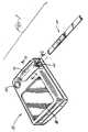
- Figure 1illustrates an exploded, perspective view, a strip 10 for applying a sample thereon and for inserting such sample laden strip 10 into an optical reading apparatus 12.
- the embodiments of the strip 10 and apparatus 12will generally be described hereinafter in terms of detection and quantification of glucose but it will be understood by those skilled in the art that the teachings herein are not limited to glucose determinations, and instead may be applied to other analyte determinations.
- the strip 10, the apparatus 12 and their respective component partsshall all be described as being in the orientation shown in the drawings and terms such as “the bottom” and “the top” shall be employed consistent with such orientation. It will be appreciated, however, that this method of description is merely convenient and that in no way is the invention restricted to such orientation and, in fact, the strip and strip holder may be rotated through any angle relative to the apparatus and the teachings herein shall still apply.
- the strip 10is adapted to be inserted longitudinally, into an opening 14 of a strip holder 16 carried on apparatus 12.
- Strip holder 16shown in more detail in Figures 2 and 3 , is preferably removable from apparatus 12 for cleaning.
- the apparatus 12is provided on its visible surface with a screen 18 on which messages, instructions, error warnings, and most importantly, results may be displayed by means such as liquid crystal displays as are well known in the art. Such information may be conveyed by letters, words, numbers or icons.
- apparatus 12is provided with a power switch for activating the apparatus, preferably with batteries and such power switch is shown as push button 20 on the drawings.
- the strip holder 16is comprised of an upper guide 22 and a lower guide 24 which together form a channel or strip passageway 26 into which the strip is inserted via opening 14.
- the extent of insertion of the stripis determined by strip impeding wall 31. It should be noted that the passageway 26 is canted at an angle with respect to the plane of the bottom 28 of the apparatus 12, so as to facilitate the insertion of strip 10 into the apparatus when the apparatus is sitting on a flat surface.
- the lower guide 24is provided with an aperture 30 through which the bottom surface 11 of the strip 10 can be “seen” by the optics located below lower guide 24.
- the aperture 30is positioned along the lower guide 24 so as to "see” the bottom surface of a reaction zone of strip 10 when the strip 10 is fully inserted into passageway 26.
- optic block 32contains a light emittinq diode (LED) 36 capable of directing light through aperture 30, upon a surface such as the lower surface 11 of the strip.
- the light emitting diodeis preferably one which emits light of essentially a uniform wavelength in rapid bursts, hereinafter referred to as "chops", for a period of time, each time it is activated.
- Chopsa uniform wavelength in rapid bursts
- the optic block 32also comprises a photodetector 38, a device capable of intercepting light reflected from the surface upon which the LED's focus and converting such light into a measurable voltage.
- bias means 40which is adapted to be biased toward the upper surface 42 of the lower guide in the area of the aperture 30 so as to ensure that the portion of the strip 10 lying over the aperture 30 is flat and presents an optically consistent surface to the optics.
- bias means 40comprises an elastomeric membrane having, on its surface opposing the aperture, a ring-like projecting gasket 44 which is adapted to bear against the strip when in place and hold the strip flat to the aperture.
- a colored targetpreferably gray, hereinafter referred to as the "gray target” 45.
- the gray target 45presents to the optics a surface for assuring the correct calibration of the apparatus before the strip is inserted. Additionally, it is the gray target that is "seen” by the optics once the apparatus is turned on and before a strip is inserted.
- the bias means 40may take forms other than that of an elastomeric membrane.
- a leaf springcan be used as such bias means.
- LFS-34incorporated herein by reference
- such alternative bias meansare described and include a particularly useful means in which the passageway 26 is designed in a serpentine configuration which in combination with a strip having spring properties serves to function as a bias means.
- Such a passagewayis illustrated in Figures 7 wherein upper guide 22 and lower guide 24 are illustrated.
- Table 1recites preferred dimensions for the angles, distances and radii; all based on the X,Y coordinates shown in the Figure.
- TALBE 1 - DIMENSIONS FOR FIGURE 7 ANGLES(Degrees) A 26 B 17 C 9 DISTANCES (Inches) L 1 0.562 L 2 0.467 L 3 0.184 L 4 0.013 CURVATURE RADIUS (Inches) CENTER (X,Y In) R 1 0.2 0.207, 0.179 R 2 0.347 0.391, 0.300 R 3 0.100 0.417, 0.006 R 4 2.635 0.412, 2.603
- FIG. 4illustrated therein is a perspective view of the bottom major surface 43 of a strip 46 embodying the teachings of this invention.
- the strip 46comprises an elongate and generally rectangular support 47 onto which is attached a test pad 48 containing reactants and provided with an overlying transport medium 50.
- the sampleis to be applied to the top surface of the transport medium 50 overlying the test pad 48.
- a portion of the samplepenetrates through the test pad and any glucose present reacts with the reactants therein to produce a color change which is visible on the bottom surface of the test pad.
- a support aperture 52is provided through the support for aligning with aperture 30 in the lower guide of the apparatus when the strip is fully inserted therein, so that a portion of the bottom of the surface of the test pad will be visible to the optics of the apparatus (such portion hereinafter, the reaction zone).
- the transport medium 50comprises pores which draw the sample therethrough by capillary action.
- the transport mediummay be composed of natural materials such as cotton or paper, as well as such synthetic materials as polyesters, polyamides, polyethylene and the like.
- the transport mediumhas pores having an effective diameter in the range of about 20 microns to about 350 microns, preferably about 50 to about 150 microns, e.g., 100 microns.
- the transport mediumis generally hydrophilic or may be rendered hydrophilic by treatment with surfactants compatible with red blood cells.
- One such compatible surfactantis MAPHOSTM 66 sold by Mazer Chemical, a division of PPG Industries Inc. Chemicals of Gurnee, Illinois.
- the transport mediumis capable of absorbing blood samples of up to about 20 to about 40 microliters e.g., 30 microliters.
- the transport mediummay be, for example, a filter paper or sintered plastic material, such as those porous polyethylene materials commonly available from the Porex Corp. of Fairburn, Georgia.
- the transport mediumis generally fabricated to have a thickness of about 0.022 inch, with about 0.25 inch width and about 1.0 inch length.
- the transport mediumis treated with a red blood cell compatible surfactant solution. Since only about 3 to about 5 microliters of blood are required to saturate the testing pad, the transport medium will preferably possess a small void volume in order not to require large volumes of blood. Excess blood applied to the reagent strip is absorbed and held in the portion of the transport medium which extends beyond the test pad.
- test padis a hydrophilic porous matrix to which reagents may be covalently or non-covalently bound.
- suitable materialinclude polyamides, which are conveniently condensation polymers of monomers of from 4 to 8 carbon atoms, where the monomers are lactams or combinations of diamines and dicarboxylic acids, polysulfones, polyesters, polyethylene, and cellulose based membranes. Other polymeric compositions may also be used.
- the polymer compositionsmay be modified to introduce other functional groups so as to provide for charged structures, so that the surfaces may be neutral, positive, or negative, as well as neutral, basic, or acidic.
- the material of choiceis a hydrophilic, anisotropic polysulfone membrane having pores varying in size from large to small through the thickness of the matrix.
- the preferred matrixis obtained from the Memtec America corporation of Maryland and has an average pore size ranging from 0.34 to 0.4 micrometers e.g., 0.37 and a thickness of from about 125 to about 140 micrometers e.g., 130 micrometers.
- the ratio of the average diameter of the large to the small poresis about 100.
- Transport medium 50is attached to the test pad 48 by an adhesive (not shown).
- Suitable adhesives for this purposeincluding acrylic, rubber, and ethylene vinyl acetate (EVA) based formulations. Particularly useful are the hot melt adhesives known in the art.
- the adhesivemay be placed in continuous stripes located only near the perimeter of the test pad, leaving a central portion of the receiving surface of the test pad substantially unobstructed.
- the transport layerwhen the transport layer is composed of a material that fuses at industrially practical temperatures, the transport layer may be attached directly to the test pad by an application of heat and pressure. The transport layer is heated until it begins to melt and then pressed against the testing pad and cooled. Direct attachment of the transport layer to the testing pad by fusion obviates any need for a distinct adhesive layer.
- the adhesive layerconnects the transport medium to the sample receiving surface of the test pad.
- the transport mediumis adapted to accept a whole blood sample and transport a detectable portion of the sample to the receiving surface by capillary action.
- the transport mediumpreferably extends past one or more ends of the test pad so as to form a reservoir for holding excess amounts of blood sample which may be present during actual use. It is usually more desirable to retain such excess amounts of the blood sample in the transport medium, rather than allowing the excess to drip upon the user or upon the viewing means in an uncontrolled fashion. Accordingly, it is preferred that the transport medium be capable of holding from about 20 to about 40 microliters of blood, preferably about 30 microliters of blood and of passing from about 3 to about 5 microliters of blood to the test pad.
- the test padis impregnated with a color forming reagent system specific to an analyte.
- Typical analytesare glucose, cholesterol, urea, and many others which will readily occur to those skilled in the art.
- the color forming reagent systemincludes an enzyme which selectively catalyzes a primary reaction with the analyte of interest.
- a product of the primary reactionmay be a dye which undergoes a change in color that is detectable at the reaction zone.
- the product of the primary reactionmay be an intermediate which undergoes another reaction, preferably also enzyme catalyzed, and participates in a secondary reaction which, directly or indirectly, causes a dye to undergo a change in color which is detectable at the reaction zone.
- An exemplary color-forming reagent systemis the system which is specific to glucose and contains glucose oxidase, a peroxidase, and an oxidizable dye.
- Glucose oxidaseis an enzyme, usually obtained from Aspergillus Niger or Penicillium, that reacts with glucose and oxygen to produce gluconolactone and hydrogen peroxide.
- the hydrogen peroxide so producedcatalyzed by a peroxidase enzyme such as horseradish peroxidase, oxidizes a dye.
- the resulting chromophore(the oxidized dye) exhibits a color that may be observed at the reaction zone.
- oxidizable dyesare known in the art including, for example, those set out in U.S. Patent 5,304,468 , incorporated herein by reference.
- One particularly useful oxidizable dyeis the 3-methyl-2 benzothiazolinone hydrazone hydrochloride/8-amilino 1-naphthalenesulfonate dye couple (MBTH/ANS couple) described in copending U.S. patent application Serial No. 245,940, filed May 19, 1994 (LFS-30).
- MBTH/ANS couple3-methyl-2 benzothiazolinone hydrazone hydrochloride/8-amilino 1-naphthalenesulfonate dye couple
- the support 46may be of a material that is sufficiently rigid to be inserted into the apparatus without undue bending or kinking.
- such supportcomprises materials such as polyolefins (e.g., polyethylene or polypropylene), polystyrene or polyesters.
- a preferred materialis the polyester available from the Imperial Chemical Industries, Ltd. of the United Kingdom, sold by them under the trademark Melinex 329 and having a thickness of about 0.014 inches.
- the bottom surface of the strip(i.e., the surface to be inserted in face-to-face relationship with the aperture 30 of the lower guide of the apparatus and hence the surface "seen” by the optics of the apparatus), presents a reaction zone 54 comprising the portion of the test pad 48 visible through the support aperture 52.
- the reaction zone 54is longitudinally placed between the leading edge 56 of the strip (leading with respect to insertion into the apparatus) and the opposite edge.
- the portion of the major surface 43 leading the reaction zone 54includes an optically visible area; (i.e., visible to the optics of the apparatus 12 as the strip is inserted therein) defining an orientation index zone 58.
- this orientation index zone 58is located at the extreme leading edge of the leading portion of the major surface 43.
- the orientation index zone 58is characterized as having a low reflectance relative to that of the area of the major surface 43 contiguous to the orientation index zone 58.
- Figure 5illustrates an alternative embodiment 62 of the strip.
- the strip 62comprises a support 64 having a major surface 66 with an aperture 68 therethrough for viewing a reaction zone 70 of a test pad 72.
- the test padis again provided with a transfer medium 74.
- an orientation index zone 76is placed on the leading portion of a major surface 66 but in this instance adjacent to the aperture 70.
- the orientation index zone 76is characterized as having a low reflectance relative to that of the areas of the major surface 66 contiguous thereto.
- the opticswill detect a sharp decrease in reflected light.
- the desired low relative reflectance of the orientation index zonemay be achieved on a major surface of a strip of this invention by any number of ways as will occur to one skilled in the art.
- the supportmay have laminated to it, in a desired region, a layer having the requisite reflectance.
- the material comprising the supportmay have incorporated therein a coloring material imparting the proper reflectance to the region comprising the orientation index zone.
- the coloring materialmay be printed or painted onto the appropriate region.
- the reflectance of the contiguous portion of the major surfaceis at least 1.5 times that of the reflectance of orientation index zone 58.
- the reflectanceshould be at least two times as high.
- the reflectance of the orientation zoneis no more than two thirds of the reflectance of the contiguous portion of the major surface.
- the reflectanceshould be only half that of the contiguous portion.
- the microprocessor of the apparatusmay be programmed to sense the difference between the reflectance of an empty passageway, i.e., the reflectance of the gray target in the embodiment illustrated herein, and that of the orientation index zone.
- the reflectance of the orientation zoneshould be less than 0.9 times the reflectance of the gray target. Preferably this value is less than 0.5 times.
- the length of the orientation index zonemust be sufficient in the direction of insertion so as to provide the optics with adequate time to produce a number of readings and, hence, experience the change in reflectance across the interface. Accordingly, the length in the direction of insertion is from 0.125 cm to 1 cm (0.05 to 0.4 inches) and preferably such length should be from about 0.15 to about 0.25 inches.
- the area of the major surface leading the reaction zonecomprises a standard zone exhibiting high reflectance.
- the reflectance of this standard zoneis calibrated and used together with reflectance of the reaction zone to calculate the quantity of analyte present in a sample.
- the portions of the major surface leading the reaction zoneare provided to have such high relative reflectance and, hence, may serve as the standard zone in accordance with the teachings of the above-referenced patent application.
- the stripis "read" by the apparatus as it is being inserted into the apparatus and the various areas of the leading major surface pass over the aperture 30 of the apparatus making such areas visible to the optics.
- the reaction zoneoverlies the aperture 30 and is read. Reading is accomplished by directing light from a light emitting diode onto the visible surface and detecting the light reflected from such surface.
- LEDS emitting lightat wavelengths of 660 and 940 nanometers are preferred.
- the reflectance of the surface presented to the opticsis measured in multiple readings as the strip is inserted into the apparatus. These multiple readings are taken as the strip moves continuously through various positions in spaced periods of time. Each such reading comprises a number of bursts of energy imparted to the LED in response to directions from a microprocessor. These bursts, referred to as chops, control the amount of light energy directed to the surface for each reading, i.e., at a constant power level, the greater the number of chops the greater amount of light energy incident upon the surface being measured.
- the light energy reflected by the surface during each readingis captured by a photodetector and converted into a measurable signal by a dual slope analog to digital converter.
- Figure 6is a plot of the counts or quantity of detected light reflected from the surface presented to the aperture as a function of time as the apparatus is turned on and then the strip of Figure 4 is inserted therein.
- the measured reflectanceis that of the gray target which is chosen to be of moderately low reflectance value.
- the reflectance measuredis that of the orientation index zone; e.g., zone 58 in Figure 4 . As seen in Figure 6 , this results in a sharp detected drop in reflectance.
- the microprocessor of the apparatusmay be programmed to accept a strip causing such a sharp initial drop as a properly inserted strip and, hence, continue with the operation of the instrument or, failing to detect such a drop, report that the strip has been inserted improperly.
- the reading of the reflectancemay continue as the orientation zone passes over the aperture.
- the microprocessormay be programmed to accept the strip causing such a sharp increase as a properly inserted strip and to continue with the operation of the instrument. Again, failing to detect such increase, the microprocessor can report that the strip has been inserted improperly.
- the reflectance of the white zone and the reflectance of the reaction zoneare read and the analyte concentration is determined as a function of these values.
Landscapes
- Health & Medical Sciences (AREA)
- Life Sciences & Earth Sciences (AREA)
- Immunology (AREA)
- Engineering & Computer Science (AREA)
- Chemical & Material Sciences (AREA)
- Hematology (AREA)
- Biomedical Technology (AREA)
- Molecular Biology (AREA)
- Urology & Nephrology (AREA)
- Physics & Mathematics (AREA)
- General Health & Medical Sciences (AREA)
- Analytical Chemistry (AREA)
- General Physics & Mathematics (AREA)
- Pathology (AREA)
- Biochemistry (AREA)
- Food Science & Technology (AREA)
- Medicinal Chemistry (AREA)
- Microbiology (AREA)
- Cell Biology (AREA)
- Biotechnology (AREA)
- Biophysics (AREA)
- Investigating Or Analysing Biological Materials (AREA)
- Investigating Or Analysing Materials By The Use Of Chemical Reactions (AREA)
- Investigating Or Analyzing Non-Biological Materials By The Use Of Chemical Means (AREA)
- Investigating Or Analysing Materials By Optical Means (AREA)
Abstract
Description
- The present invention relates to a test device and method for the optical determination of analytes in aqueous fluids, particularly whole blood. In one preferred embodiment it concerns a test device and method for optically measuring the concentration of glucose in whole blood.
- The quantification of chemical and biochemical components in colored aqueous fluids, in particular colored biological fluids such as whole blood and urine and biological fluid derivatives such as blood serum and blood plasma, is of ever-increasing importance. Important applications exist in medical diagnosis and treatment and in the quantification of exposure to therapeutic drugs, intoxicants, hazardous chemicals and the like. In some instances, the amounts of materials being determined are either so minuscule--in the range of a microgram or less per deciliter--or so difficult to precisely determine that the apparatus employed is complicated and useful only to skilled laboratory personnel. In this case the results are generally not available for some hours or days after sampling. In other instances, there is often an emphasis on the ability of lay operators to perform the test routinely, quickly and reproducibly outside a laboratory setting with rapid or immediate information display.
- one common medical test is the measurement of blood glucose levels by diabetics. Current teaching counsels diabetic patients to measure their blood glucose level from two to seven times a day depending on the nature and severity of their individual cases. Based on the observed pattern in the measured glucose levels, the patient and physician together make adjustments in diet, exercise and insulin intake to better manage the disease. Clearly, this information should be available to the patient immediately.
- Currently a method widely used in the United States employs a test article of the type described in
U.S. Patent 3,298,789 issued January 17, 1967 to Mast. In this method a sample of fresh, whole blood (typically 20-40 µl) is placed on an ethylcellulose-coated reagent pad containing an enzyme system having glucose oxidase and peroxidase activity. The enzyme system reacts with glucose and releases hydrogen peroxide. The pad also contains an indicator which reacts with the hydrogen peroxide in the presence of peroxidase to give a color proportional in intensity to the sample's glucose level. - Another popular blood glucose test method employs similar chemistry but uses, in place of the ethylcellulose-coated pad, a water-resistant film through which the enzymes and indicator are dispersed. This type of system is disclosed in
United States Patent 3,630,957 issued December 28, 1971 to Rey et al. - In both cases the sample is allowed to remain in contact with the reagent pad for a specified time (typically one minute). Then, in the first case, the blood sample is washed off with a stream of water while in the second case, it is wiped off the film. The reagent pad or film is then blotted dry and evaluated. The evaluation of the analyte concentration is made either by comparing color generated with a color chart or by placing the pad or film in a diffuse reflectance instrument to read a color intensity value.
- While the above methods have been used in glucose monitoring for years, they do have certain limitations. The sample size required is rather large for a finger stick test and is difficult to achieve for some people whose capillary blood does not express readily.
- In addition, these methods share a limitation with other simple lay-operator colorimetric determinations in that their result is based on an absolute color reading which is in turn related to the absolute extent of reaction between the sample and the test reagents. The fact that the sample must be washed, blotted or wiped off the reagent pad after the timed reaction interval requires that the user be ready at the end of the timed interval and wipe or apply a wash stream at the required time. The fact that the reaction is stopped by removing the sample leads to some uncertainty in the result, especially in the hands of the home user. Overwashing, overblotting or overwiping can give low results and underwashing can give high results.
- Another problem that often exists in simple lay-operator determinations is the necessity for initiating a timing sequence when blood is applied to a reagent pad. A user will typically have pricked his or her finger to obtain a blood sample and will then be required to simultaneously apply the blood from the finger to a reagent pad while starting a timer with his or her other hand, thereby requiring the use of both hands simultaneously. This is particularly difficult since it is often necessary to ensure that the timer is started only when blood is applied to the reagent pad. All of the prior art methods require additional manipulations or additional circuitry to achieve this result. Accordingly, simplification of this aspect of reflectance reading instruments is desirable.
- Great improvements have been achieved upon the introduction of the systems described in
U.S. Patents 5,179,005 ,5,059,394 ,5,049,487 , and4,935,346 wherein an apparatus is provided for accepting a test strip having a test pad, one surface of which comprises a reaction zone adapted to be optically readable by said apparatus. The test strip is inserted into the apparatus, the apparatus is started and then whole blood is applied onto the test pad. At least a portion of such blood is allowed to permeate to the reaction zone whereby any analyte present therein will react with color-producing reagents in the test pad to alter the light reflectivity characteristics of the reaction zone. The reflectivity of the reaction zone is then a measure of the presence and/or quantity of analyte present in the blood sample. As described in the aforementioned patents, this system does not require a large sample of blood nor does it require the user to undertake timed manipulations with respect to the beginning or end of the reaction. Instead, because the strip is first inserted into the apparatus prior to the application of the sample, a standard reflectance reading of the reaction zone in the dry state may be obtained. The beginning of the reaction can be detected by the first "breakthrough" of the liquid sample onto the reaction zone by monitoring the reflectance and comparing the reading to the standard reflectance of the dry reaction zone. A reflectance reading taken at a predetermined time after the reaction has begun and compared to the standard reflectance, i.e., the dry reaction zone reading, will be indicative of the quantity of analyte present in the sample. - While the above described system does indeed solve the problems of the prior art and relieves the user of the burden of measurement and timing, it does require that the user apply a sample of blood onto the strip while the strip is in the apparatus. For the most part this represents no problem to the vast majority of users. However, certain users suffer from handicaps such as poor vision or impaired motor coordination so that the accurate application of blood from such users' pricked fingers to the strip, in place on the apparatus, represents a hardship. Further, for institutional users, for example, there is the possibility that some quantity of blood remains on the device from a prior user, since the systems necessitate applying one's pricked finger to the device. In such instances there is the need to disinfect the device between users.
- Accordingly, for the above reasons, in the case of at least some users, it would be preferable to first apply the blood sample to the strip prior to inserting the strip into the apparatus. Unfortunately, by doing so the apparatus no longer has the capability of reading reflectance of the dry, unreacted, reaction zone, i.e., at no time is the dry reaction zone presented to the apparatus. This reading was necessary in the prior devices to provide a calibration standard for determining the reflectance change as a result of the reaction and hence the presence and/or quantity of the analyte in the sample.
- In a commonly assigned, copending U.S. patent application filed today entitled "Optically Readable Strip For Analyte Detection Having On-strip Standard", bearing our internal docket number LFS-32 and incorporated herein by reference, there is described a strip, apparatus, and methodology for allowing the user to apply a sample to the strip before inserting it into the reading apparatus while also providing a calibrated standard. This above-referenced patent application teaches a strip which comprises a portion for having the liquid applied thereto, this portion having an optically visible surface (i.e., at least with respect to the optics of the apparatus to be employed with the strip) defining a reaction zone. The reaction zone is such that its reflectance varies as a function of the quantity of analyte present in the applied liquid. Preferably, such is accomplished by the analyte, if present, reacting with reactants to produce a color change of the reaction zone. The test strip further comprises an optically visible standard zone of high reflectance, relative to the reflectance of the reaction zone. The standard zone is positioned on the strip so as to lead the reaction zone as the strip is inserted into the apparatus.
- Accordingly, the apparatus may be provided with optical means for sequentially determining the reflectance value of the standard zone as the strip is being inserted into its fully inserted position in the apparatus and the reflectance value of the reaction zone after the strip has been inserted. Additionally, the apparatus is provided with means for calculating the presence and/or quantity of the analyte in question as a function of the standard zone reflectance and the reaction zone reflectance.
- Owing to the configuration of the strip as described and specifically, the provision of a standard zone leading the reaction zone, the aforementioned apparatus need be provided with only one set of optics, e.g., one light emitting diode and one light detector for reading the reflection at a single position along the path of the strip.
- In operation, the user turns on the apparatus, applies the sample to a fresh strip and then inserts the strip fully into the apparatus and reads the results. Without intervention of the user, the strip, configured as described, allows the apparatus to read the reflectance of light incident upon the standard zone as it passes the optics of the apparatus as the strip is inserted. This reading is then calibrated to account for variations owing to changes in the apparatus from the factory condition and to lot-to-lot variations in the strip. The fully inserted strip thereafter presents the reaction zone to the optics of the apparatus and the reflectance of this surface may be read. Means are provided for the apparatus to calculate and report the analyte presence or concentration as a function of these readings.
- The above-described system has gone a long way toward easing the user's task in determining analyte concentration. It will be appreciated, however, that it is fundamental to the successful optical reading of a strip on which liquid has been applied, that the strip be properly oriented when inserted into the apparatus.
- Specifically, in a surprising number of cases, the strip is improperly introduced upside down with a resultant erroneous reading. At best, such an error, if not caught immediately, requires discarding the strip, which can be contaminated or otherwise altered in the erroneous attempt to use it upside down and repeating the process with a fresh strip. Obviously, in the case of a blood sample requiring another finger pricking, this is highly undesirable. In the worst case, the erroneous results may be accepted by the user with potentially adverse consequences.
- A prior art device, sold by the Boehringer-Mannheim Company under the trademark Accutrend® and described in a brochure entitled "Evaluation Report Accutrend®" published by Boehringer-Mannheim Company in 1991, is provided with a black band on the trailing end of the strip. The apparatus for use with such a strip appears to be provided with two sets of optics; one to read a first zone and the second to read the black band. It appears that the apparatus is provided with microprocessing means for recording the absence of detection of such black band by the second set of optics. Such absence would be indicative of the strip having been inserted upside down. Unfortunately, the syster adds great complexity and costs to design and manufacture of the apparatus in that two sets of optics are required. Moreover, any detection of an improperly inserted strip occurs only after the entire operation; i.e., insertion of the strip, has been completed; that is to say, at the last possible moment.
- Accordingly, there is a need to provide a system wherein the upside down insertion of a strip is immediately detected and to accomplish this without the need for expensive modification of the strip reading apparatus.
- In accordance with the teachings of this invention, a strip, method and apparatus are provided for determining the presence or quantity of analyte or liquid by inserting the strip into an optical reading apparatus wherein means are provided for rapidly and simply affirming that the strip has not been inserted upside down with respect to the optics of the apparatus.
- Accordingly, the invention provides a test strip as claimed in claim 1 or claim 3. Furthermore, the invention provides an apparatus as claimed in claim 4 and a method as claimed in claim 5. Thus, the strip comprises a portion for having a liquid (e.g. blood) applied thereto. This portion has an optically visible area on a major surface of the strip defining a reaction zone which varies in reflectance as a function of the quantity of analyte present in the applied liquid. The test strip is further provided with an optically visible area on the same major surface which defines an orientation index zone and is positioned within that portion of such major surface leading the reaction zone as the strip is inserted into the apparatus. The orientation index zone is selected to have a contrasting reflectance relative to the areas of the major surface contiguous with this orientation index zone. Accordingly, the apparatus, utilizing the same optics provided to read the reflectance of the reaction zone once the strip is fully inserted, also employs such optics to sequentially determine the reflectance value of the portion of the major leading surface of the strip as the strip is being inserted into the apparatus. Such optics will experience a sharp change in reflectance as the interface between the orientation index zone and the areas of the major surface contiguous therewith pass over the optics; such change being indicative of a properly inserted strip. Microprocessing means are provided in the apparatus for processing the reflectance experienced by the optic system and for either detecting the presence of the orientation index or for reporting its absence.
- In view of the above teachings, it can be seen that merely by positioning an orientation index zone on the leading portion of the surface to be read, the detection of an upside down strip can be made at the earliest possible moment as the strip is being inserted with no need for additional optical equipment.
- The present invention can be more readily understood by reference to the following detailed description when read in conjunction with the attached drawings wherein:
Figure 1 is an exploded, perspective view of a strip and apparatus embodying the teachings of this invention;Figure 2 is a partial, longitudinal, cross-sectional view taken along line 2-2 ofFigure 1 and illustrating the strip fully inserted into the apparatus;Figure 3 is a partial, transverse, cross-sectional view, taken along line 3-3 ofFigure 1 and illustrating the strip fully inserted into the apparatus;Figure 4 is a perspective view illustrating the leading portion of the major surface of a first embodiment of the strip of this invention;Figure 5 is a perspective view illustrating a major surface of a second embodiment of the strip of this invention;Figure 6 is a graphical depiction of the detection of reflected light as the strip ofFigure 4 is inserted into an optical reading apparatus; andFigure 7 is a cross-sectional view of a strip passageway of an embodiment of an apparatus employing the teachings of this invention.- Turning now to the drawings,
Figure 1 illustrates an exploded, perspective view, astrip 10 for applying a sample thereon and for inserting such sampleladen strip 10 into anoptical reading apparatus 12. The embodiments of thestrip 10 andapparatus 12 will generally be described hereinafter in terms of detection and quantification of glucose but it will be understood by those skilled in the art that the teachings herein are not limited to glucose determinations, and instead may be applied to other analyte determinations. Further, for the purposes of simplification and clarity, thestrip 10, theapparatus 12 and their respective component parts shall all be described as being in the orientation shown in the drawings and terms such as "the bottom" and "the top" shall be employed consistent with such orientation. It will be appreciated, however, that this method of description is merely convenient and that in no way is the invention restricted to such orientation and, in fact, the strip and strip holder may be rotated through any angle relative to the apparatus and the teachings herein shall still apply. - As can be seen in
Figure 1 , thestrip 10 is adapted to be inserted longitudinally, into anopening 14 of astrip holder 16 carried onapparatus 12.Strip holder 16, shown in more detail inFigures 2 and 3 , is preferably removable fromapparatus 12 for cleaning. Theapparatus 12 is provided on its visible surface with ascreen 18 on which messages, instructions, error warnings, and most importantly, results may be displayed by means such as liquid crystal displays as are well known in the art. Such information may be conveyed by letters, words, numbers or icons. Additionally,apparatus 12 is provided with a power switch for activating the apparatus, preferably with batteries and such power switch is shown aspush button 20 on the drawings. - Referring now to
Figures 2 and 3 , illustrated therein in longitudinal and transverse cross-sectional views respectively, is theremovable strip holder 16 with astrip 10 fully inserted therein, together with fragmentary views of the adjacent parts of theapparatus 12. Thestrip holder 16 is comprised of anupper guide 22 and alower guide 24 which together form a channel orstrip passageway 26 into which the strip is inserted viaopening 14. The extent of insertion of the strip is determined bystrip impeding wall 31. It should be noted that thepassageway 26 is canted at an angle with respect to the plane of the bottom 28 of theapparatus 12, so as to facilitate the insertion ofstrip 10 into the apparatus when the apparatus is sitting on a flat surface. - The
lower guide 24 is provided with anaperture 30 through which the bottom surface 11 of thestrip 10 can be "seen" by the optics located belowlower guide 24. As will be understood hereinafter, theaperture 30 is positioned along thelower guide 24 so as to "see" the bottom surface of a reaction zone ofstrip 10 when thestrip 10 is fully inserted intopassageway 26. - The optics for the apparatus are located in
optic block 32 affixed toapparatus 12.optic block 32 contains a light emittinq diode (LED) 36 capable of directing light throughaperture 30, upon a surface such as the lower surface 11 of the strip. The light emitting diode is preferably one which emits light of essentially a uniform wavelength in rapid bursts, hereinafter referred to as "chops", for a period of time, each time it is activated. For the purposes of glucose determination it has been found preferable to employ two such LED's, each emitting light at a different wavelength and preferably at 660 and 940 nanometers (LED 660 and LED 940, respectively). Theoptic block 32 also comprises aphotodetector 38, a device capable of intercepting light reflected from the surface upon which the LED's focus and converting such light into a measurable voltage. - Incorporated into the
upper guide 22 is bias means 40 which is adapted to be biased toward theupper surface 42 of the lower guide in the area of theaperture 30 so as to ensure that the portion of thestrip 10 lying over theaperture 30 is flat and presents an optically consistent surface to the optics. As illustrated in the drawings, bias means 40 comprises an elastomeric membrane having, on its surface opposing the aperture, a ring-like projectinggasket 44 which is adapted to bear against the strip when in place and hold the strip flat to the aperture. Centered within the ring-like projection is a colored target, preferably gray, hereinafter referred to as the "gray target" 45. Thegray target 45 presents to the optics a surface for assuring the correct calibration of the apparatus before the strip is inserted. Additionally, it is the gray target that is "seen" by the optics once the apparatus is turned on and before a strip is inserted. - The bias means 40 may take forms other than that of an elastomeric membrane. For example, a leaf spring can be used as such bias means. In a copending, commonly assigned U.S. patent application filed today and bearing our internal docket number LFS-34 (incorporated herein by reference), such alternative bias means are described and include a particularly useful means in which the
passageway 26 is designed in a serpentine configuration which in combination with a strip having spring properties serves to function as a bias means. Such a passageway is illustrated inFigures 7 whereinupper guide 22 andlower guide 24 are illustrated. - Table 1, below, recites preferred dimensions for the angles, distances and radii; all based on the X,Y coordinates shown in the Figure.
TALBE 1 - DIMENSIONS FOR FIGURE 7 ANGLES (Degrees) A 26 B 17 C 9 DISTANCES (Inches) L1 0.562 L2 0.467 L3 0.184 L4 0.013 CURVATURE RADIUS (Inches) CENTER (X,Y In) R1 0.2 0.207, 0.179 R2 0.347 0.391, 0.300 R3 0.100 0.417, 0.006 R4 2.635 0.412, 2.603 - Referring now to
Figure 4 illustrated therein is a perspective view of the bottommajor surface 43 of astrip 46 embodying the teachings of this invention. - In the embodiment described herein for detecting glucose in whole blood, the
strip 46 comprises an elongate and generallyrectangular support 47 onto which is attached atest pad 48 containing reactants and provided with anoverlying transport medium 50. In use the sample is to be applied to the top surface of thetransport medium 50 overlying thetest pad 48. A portion of the sample penetrates through the test pad and any glucose present reacts with the reactants therein to produce a color change which is visible on the bottom surface of the test pad. Asupport aperture 52 is provided through the support for aligning withaperture 30 in the lower guide of the apparatus when the strip is fully inserted therein, so that a portion of the bottom of the surface of the test pad will be visible to the optics of the apparatus (such portion hereinafter, the reaction zone). - Details of these components of the strip are described in copending
U.S. Serial No. 881,970 , filed on May 12, 1992 and incorporated herein by reference. Briefly, thetransport medium 50 comprises pores which draw the sample therethrough by capillary action. The transport medium may be composed of natural materials such as cotton or paper, as well as such synthetic materials as polyesters, polyamides, polyethylene and the like. - The transport medium has pores having an effective diameter in the range of about 20 microns to about 350 microns, preferably about 50 to about 150 microns, e.g., 100 microns. The transport medium is generally hydrophilic or may be rendered hydrophilic by treatment with surfactants compatible with red blood cells. One such compatible surfactant is
MAPHOS™ 66 sold by Mazer Chemical, a division of PPG Industries Inc. Chemicals of Gurnee, Illinois. In a preferred embodiment, the transport medium is capable of absorbing blood samples of up to about 20 to about 40 microliters e.g., 30 microliters. - The transport medium may be, for example, a filter paper or sintered plastic material, such as those porous polyethylene materials commonly available from the Porex Corp. of Fairburn, Georgia. The transport medium is generally fabricated to have a thickness of about 0.022 inch, with about 0.25 inch width and about 1.0 inch length. The transport medium is treated with a red blood cell compatible surfactant solution. Since only about 3 to about 5 microliters of blood are required to saturate the testing pad, the transport medium will preferably possess a small void volume in order not to require large volumes of blood. Excess blood applied to the reagent strip is absorbed and held in the portion of the transport medium which extends beyond the test pad.
- The test pad and its preparation are also set forth in detail in
U.S. Patent 4,935,346 and need not be described in detail herein. Essentially, the test pad is a hydrophilic porous matrix to which reagents may be covalently or non-covalently bound. Examples of a suitable material include polyamides, which are conveniently condensation polymers of monomers of from 4 to 8 carbon atoms, where the monomers are lactams or combinations of diamines and dicarboxylic acids, polysulfones, polyesters, polyethylene, and cellulose based membranes. Other polymeric compositions may also be used. Further, the polymer compositions may be modified to introduce other functional groups so as to provide for charged structures, so that the surfaces may be neutral, positive, or negative, as well as neutral, basic, or acidic. The material of choice is a hydrophilic, anisotropic polysulfone membrane having pores varying in size from large to small through the thickness of the matrix. The preferred matrix is obtained from the Memtec America corporation of Maryland and has an average pore size ranging from 0.34 to 0.4 micrometers e.g., 0.37 and a thickness of from about 125 to about 140 micrometers e.g., 130 micrometers. The ratio of the average diameter of the large to the small pores is about 100. Transport medium 50 is attached to thetest pad 48 by an adhesive (not shown). Suitable adhesives for this purpose, including acrylic, rubber, and ethylene vinyl acetate (EVA) based formulations. Particularly useful are the hot melt adhesives known in the art. The adhesive may be placed in continuous stripes located only near the perimeter of the test pad, leaving a central portion of the receiving surface of the test pad substantially unobstructed.- Alternatively, when the transport layer is composed of a material that fuses at industrially practical temperatures, the transport layer may be attached directly to the test pad by an application of heat and pressure. The transport layer is heated until it begins to melt and then pressed against the testing pad and cooled. Direct attachment of the transport layer to the testing pad by fusion obviates any need for a distinct adhesive layer.
- The adhesive layer connects the transport medium to the sample receiving surface of the test pad. The transport medium is adapted to accept a whole blood sample and transport a detectable portion of the sample to the receiving surface by capillary action. The transport medium preferably extends past one or more ends of the test pad so as to form a reservoir for holding excess amounts of blood sample which may be present during actual use. It is usually more desirable to retain such excess amounts of the blood sample in the transport medium, rather than allowing the excess to drip upon the user or upon the viewing means in an uncontrolled fashion. Accordingly, it is preferred that the transport medium be capable of holding from about 20 to about 40 microliters of blood, preferably about 30 microliters of blood and of passing from about 3 to about 5 microliters of blood to the test pad.
- The test pad is impregnated with a color forming reagent system specific to an analyte. Typical analytes are glucose, cholesterol, urea, and many others which will readily occur to those skilled in the art. Preferably, the color forming reagent system includes an enzyme which selectively catalyzes a primary reaction with the analyte of interest. A product of the primary reaction may be a dye which undergoes a change in color that is detectable at the reaction zone. Alternatively, the product of the primary reaction may be an intermediate which undergoes another reaction, preferably also enzyme catalyzed, and participates in a secondary reaction which, directly or indirectly, causes a dye to undergo a change in color which is detectable at the reaction zone.
- An exemplary color-forming reagent system is the system which is specific to glucose and contains glucose oxidase, a peroxidase, and an oxidizable dye. Glucose oxidase is an enzyme, usually obtained from Aspergillus Niger or Penicillium, that reacts with glucose and oxygen to produce gluconolactone and hydrogen peroxide. The hydrogen peroxide so produced, catalyzed by a peroxidase enzyme such as horseradish peroxidase, oxidizes a dye. The resulting chromophore (the oxidized dye) exhibits a color that may be observed at the reaction zone. Many suitable oxidizable dyes are known in the art including, for example, those set out in
U.S. Patent 5,304,468 , incorporated herein by reference. One particularly useful oxidizable dye is the 3-methyl-2 benzothiazolinone hydrazone hydrochloride/8-amilino 1-naphthalenesulfonate dye couple (MBTH/ANS couple) described in copendingU.S. patent application Serial No. 245,940, filed May 19, 1994 (LFS-30). Many other suitable color-forming reagent systems specific to particular analytes are known in the art. A dye couple of choice is a derivative of MBTH, meta[3-methyl 2-benzothiazolinone hydrazone] N-sulfonyl benzenesulfonate monosodium coupled with ANS. - The
support 46 may be of a material that is sufficiently rigid to be inserted into the apparatus without undue bending or kinking. Preferably, such support comprises materials such as polyolefins (e.g., polyethylene or polypropylene), polystyrene or polyesters. A preferred material is the polyester available from the Imperial Chemical Industries, Ltd. of the United Kingdom, sold by them under the trademark Melinex 329 and having a thickness of about 0.014 inches. - Referring to
Figure 4 , the bottom surface of the strip (i.e., the surface to be inserted in face-to-face relationship with theaperture 30 of the lower guide of the apparatus and hence the surface "seen" by the optics of the apparatus), presents areaction zone 54 comprising the portion of thetest pad 48 visible through thesupport aperture 52. Thereaction zone 54 is longitudinally placed between theleading edge 56 of the strip (leading with respect to insertion into the apparatus) and the opposite edge. In accordance with the teachings of this invention, the portion of themajor surface 43 leading thereaction zone 54 includes an optically visible area; (i.e., visible to the optics of theapparatus 12 as the strip is inserted therein) defining anorientation index zone 58. As illustrated inFigure 4 , in one embodiment thisorientation index zone 58 is located at the extreme leading edge of the leading portion of themajor surface 43. Theorientation index zone 58 is characterized as having a low reflectance relative to that of the area of themajor surface 43 contiguous to theorientation index zone 58. Thus, wheninterface 60, between theorientation index zone 58 and the area contiguous thereto, passes over the optics of the apparatus as a strip is inserted, the optics will detect a sharp rise in reflected light. Figure 5 illustrates analternative embodiment 62 of the strip. As in the prior described embodiment, thestrip 62 comprises asupport 64 having amajor surface 66 with anaperture 68 therethrough for viewing areaction zone 70 of atest pad 72. The test pad is again provided with atransfer medium 74. In this embodiment, anorientation index zone 76 is placed on the leading portion of amajor surface 66 but in this instance adjacent to theaperture 70. Again, theorientation index zone 76 is characterized as having a low reflectance relative to that of the areas of themajor surface 66 contiguous thereto. Thus, for this embodiment, wheninterface 78 between theorientation index zone 76 and the area contiguous thereto passes over the optics of the apparatus as the strip is inserted therein, the optics will detect a sharp decrease in reflected light.- The desired low relative reflectance of the orientation index zone may be achieved on a major surface of a strip of this invention by any number of ways as will occur to one skilled in the art. For example, the support may have laminated to it, in a desired region, a layer having the requisite reflectance. Alternatively, the material comprising the support may have incorporated therein a coloring material imparting the proper reflectance to the region comprising the orientation index zone. As further alternatives, the coloring material may be printed or painted onto the appropriate region.
- While the method chosen for accomplishing the contrasting reflectance values between the orientation index zone and the contiguous area of the major surface is not critical, it is important that a minimal change in reflectance is exhibited across the interface between these areas. Accordingly, for the embodiment shown in
Figure 4 , the reflectance of the contiguous portion of the major surface is at least 1.5 times that of the reflectance oforientation index zone 58. Preferably, the reflectance should be at least two times as high. Similarly, for the embodiment shown inFigure 5 , the reflectance of the orientation zone is no more than two thirds of the reflectance of the contiguous portion of the major surface. Preferably, the reflectance should be only half that of the contiguous portion. - In a preferred embodiment, the microprocessor of the apparatus may be programmed to sense the difference between the reflectance of an empty passageway, i.e., the reflectance of the gray target in the embodiment illustrated herein, and that of the orientation index zone. In such case, the reflectance of the orientation zone, should be less than 0.9 times the reflectance of the gray target. Preferably this value is less than 0.5 times.
- It will be understood that these relative reflectance values are those detected by the specific apparatus using light having a wavelength of 940 nanometers.
- Further, it will be understood that the length of the orientation index zone must be sufficient in the direction of insertion so as to provide the optics with adequate time to produce a number of readings and, hence, experience the change in reflectance across the interface. Accordingly, the length in the direction of insertion is from 0.125 cm to 1 cm (0.05 to 0.4 inches) and preferably such length should be from about 0.15 to about 0.25 inches.
- In accordance with the teachings of our copending U.S. patent application LFS-32, referred to above and incorporated herein by reference, the area of the major surface leading the reaction zone comprises a standard zone exhibiting high reflectance. As is well described in the referenced patent application, the reflectance of this standard zone is calibrated and used together with reflectance of the reaction zone to calculate the quantity of analyte present in a sample. In the embodiments illustrated in
Figures 4 and 5 , the portions of the major surface leading the reaction zone (other than the orientation index zone) are provided to have such high relative reflectance and, hence, may serve as the standard zone in accordance with the teachings of the above-referenced patent application. - As described in conjunction with the drawings, the strip is "read" by the apparatus as it is being inserted into the apparatus and the various areas of the leading major surface pass over the
aperture 30 of the apparatus making such areas visible to the optics. In its final position, the reaction zone overlies theaperture 30 and is read. Reading is accomplished by directing light from a light emitting diode onto the visible surface and detecting the light reflected from such surface. When employing the teachings of this invention to detect glucose in blood, for example, LEDS emitting light at wavelengths of 660 and 940 nanometers are preferred. - As stated, the reflectance of the surface presented to the optics is measured in multiple readings as the strip is inserted into the apparatus. These multiple readings are taken as the strip moves continuously through various positions in spaced periods of time. Each such reading comprises a number of bursts of energy imparted to the LED in response to directions from a microprocessor. These bursts, referred to as chops, control the amount of light energy directed to the surface for each reading, i.e., at a constant power level, the greater the number of chops the greater amount of light energy incident upon the surface being measured. The light energy reflected by the surface during each reading is captured by a photodetector and converted into a measurable signal by a dual slope analog to digital converter.
Figure 6 is a plot of the counts or quantity of detected light reflected from the surface presented to the aperture as a function of time as the apparatus is turned on and then the strip ofFigure 4 is inserted therein. As can be seen, when the apparatus is first turned on, the measured reflectance is that of the gray target which is chosen to be of moderately low reflectance value. Immediately upon the strip being inserted, the reflectance measured is that of the orientation index zone; e.g.,zone 58 inFigure 4 . As seen inFigure 6 , this results in a sharp detected drop in reflectance. The microprocessor of the apparatus may be programmed to accept a strip causing such a sharp initial drop as a properly inserted strip and, hence, continue with the operation of the instrument or, failing to detect such a drop, report that the strip has been inserted improperly. Alternatively, the reading of the reflectance may continue as the orientation zone passes over the aperture. Upon the orientation index zone passing beyond the aperture, the contiguous zone of the leading major surface become visible to the optics, and a sharp increase in the reflectance is exhibited. At this point, the microprocessor may be programmed to accept the strip causing such a sharp increase as a properly inserted strip and to continue with the operation of the instrument. Again, failing to detect such increase, the microprocessor can report that the strip has been inserted improperly.- Assuming detection of the proper orientation of the strip, the reflectance of the white zone and the reflectance of the reaction zone are read and the analyte concentration is determined as a function of these values.
Claims (5)
- A test strip (46) for determining the presence or quantity of an analyte in a liquid by inserting said test strip (46) into an optical reading apparatus (12); said test strip (46) comprising:an elongate and generally rectangular support (47) onto which is attached a test pad (48) containing reactants and an overlying transport medium (50) for having liquid applied thereto, wherein a support aperture (52) is provided through the support (47), such that a portion of the bottom of the surface of the test pad (48) provides an optically visible area on a major surface (43) of the strip, the optically visible area defining a reaction zone (54), the reaction zone (54) being longitudinally placed between the leading edge (56) of the strip and the opposite edge, such reaction zone (54) varying in reflectance as a function of the quantity of analyte in the applied liquid;said test strip further comprising an optically visible area on said major surface (43) defining an orientation index zone (58), said orientation index zone (58) being located at the extreme leading portion of the major surface (43), said orientation index zone (58) having a low reflectance relative to that of the area of the major surface contiguous (43) to the orientation index zone (58),characterized in that there is a single orientation index zone (58), said orientation index zone (58) being positioned to lead said reaction zone (54) as said strip (46) is inserted into said apparatus (12), said orientation index zone (58) having a length, in the direction of insertion, of from 0.125 to 1 cm (0.05 to 0.4 inches);wherein the area of the major surface (43) leading the reaction zone (54), other than the orientation index zone (58), exhibits high relative reflectance and serves as a standard zone; and
wherein the reflectance of said contiguous area is at least 1.5 times the reflectance of said orientation index zone (58). - The strip of claim 1 wherein the reflectance of said contiguous area is at least two times the reflectance of said orientation index zone.
- A test strip (62) for determining the presence or quantity of an analyte in a liquid by inserting said test strip (62) into an optical reading apparatus (12); said test strip (62) comprising:a support (64) having a major surface (66) with an aperture (68) therethrough for viewing a reaction zone (70) of a test pad (72) provided with a transfer medium (74) for having liquid applied thereto, such that a portion of the bottom of the surface of the test pad (72) provides an optically visible area on a major surface (66) of the strip, the optically visible area defining a reaction zone (70), such reaction zone (70) varying in reflectance as a function of the quantity of analyte in the applied liquid;said test strip further comprising an area on said major surface (66) defining an orientation index zone (76), said orientation index zone (76) being located on the leading portion of the major surface (66) adjacent to the aperture (68), said orientation index zone (76) having a low reflectance relative to that of the area of the major surface (66) contiguous to the orientation index zone (76),characterized in that there is a single orientation index zone (76), said orientation index zone (76) being positioned to lead said reaction zone (70) as said strip (62) is inserted into said apparatus (12), and said orientation index zone (76) having a length, in the direction of insertion, of from 0.125 to 1 cm (0.05 to 0.4 inches);wherein the area of the major surface (66) leading the reaction zone (70), other than the orientation index zone (76), exhibits high relative reflectance and serves as a standard zone; and
wherein the reflectance of said orientation index zone (76) is no more than two thirds of the reflectance of the contiguous portion of the major surface (66). - An apparatus (12) for determining the presence or quantity of an analyte in a liquid applied to a test strip of claim 1 or claim 3 and inserted into said apparatus (12), said apparatus comprising:a strip holder (16) comprised of an upper guide (22) and a lower guide (24) which together form a longitudinally extending strip passageway (26) having an open end (14) for receiving said strip (10) and an opposed end (31), wherein the passageway (26) is canted at an angle with respect to the plane of the bottom (28) of the apparatus (12) so as to facilitate the insertion of the test strip (10) into the apparatus (12) when the apparatus (12) is sitting on a flat surface;wherein the lower guide (24) is provided with an aperture (30) through which the bottom surface (11) of the test strip (10) can be seen by the optics located below the lower guide (24), the aperture (30) being positioned along the lower guide (24) such that the bottom surface of the reaction zone (54/70) of the test strip (10) is visible when the test strip (10) is fully inserted into the passageway (26);
wherein a bias means (40) is incorporated into the upper guide (22) which is adapted to be biased toward the upper surface (42) of the lower guide (24) in the area of the aperture (30) so as to ensure that the portion of the strip (10) lying over the aperture (30) is flat and presents an optically consistent surface to the optics; optics located in an optic block (32) affixed to the apparatus (12) comprising a light source for directing light through aperture (30) into said passageway (26) at a position between said open end (14) and said opposed end (31); and a light detector (38) for detecting light reflected from said passageway (26), and for converting said detected reflected light into a signal; and
microprocessing means for receiving said signal to detect the presence or absence of the orientation index zone in the passageway (26);
wherein the same optics are used sequentially to determine the reflectance value of the major leading surface of the test strip (10) as the strip (10) is being inserted into the optical reading apparatus (12) such that the reflectance value of the standard zone is determined; the presence or absence of the orientation index zone (58/76) on the major surface (43/66) of the test strip (46/62) is detected; and the reflectance value of the reaction zone (54/70) is read once the strip is fully inserted into the strip passageway (26); and
wherein the presence and/or quantity of the analyte is calculated as a function of the standard zone reflectance and the reaction zone reflectance. - A method for determining that a test strip (46/62) of claim 1 or claim 3 has been properly oriented in an apparatus (12) of claim 4 for determining the presence or quantity of an analyte in a liquid applied to said strip and inserted into said apparatus (12), said method comprising:(a) applying a liquid sample to the overlying transport medium (50) of the test strip (46/62) according to claim 1 or claim 3;(b) inserting said strip into said apparatus;(c) determining the reflectance of the major surface (43/66) of the strip (46/62) by directing light at a fixed position in the pathway of the strip as it is inserted and detecting the reflected light; and(d) detecting the presence or absence of reflected light corresponding to the passage of said orientation index zone (58/76) past said fixed position as the strip is inserted into said passageway (26).
Applications Claiming Priority (3)
| Application Number | Priority Date | Filing Date | Title |
|---|---|---|---|
| US302560 | 1994-09-08 | ||
| US08/302,560US6335203B1 (en) | 1994-09-08 | 1994-09-08 | Optically readable strip for analyte detection having on-strip orientation index |
| PCT/US1995/012090WO1996007907A1 (en) | 1994-09-08 | 1995-09-07 | Optically readable strip for analyte detection having on-strip orientation index |
Publications (3)
| Publication Number | Publication Date |
|---|---|
| EP0779983A1 EP0779983A1 (en) | 1997-06-25 |
| EP0779983B1 EP0779983B1 (en) | 1999-11-17 |
| EP0779983B2true EP0779983B2 (en) | 2008-08-13 |
Family
ID=23168269
Family Applications (1)
| Application Number | Title | Priority Date | Filing Date |
|---|---|---|---|
| EP95934497AExpired - LifetimeEP0779983B2 (en) | 1994-09-08 | 1995-09-07 | Optically readable strip for analyte detection having on-strip orientation index |
Country Status (15)
| Country | Link |
|---|---|
| US (3) | US6335203B1 (en) |
| EP (1) | EP0779983B2 (en) |
| JP (1) | JP3452067B2 (en) |
| KR (1) | KR100350821B1 (en) |
| CN (1) | CN1134664C (en) |
| AT (1) | ATE186780T1 (en) |
| AU (1) | AU688979B2 (en) |
| CA (1) | CA2199491C (en) |
| DE (1) | DE69513409T2 (en) |
| DK (1) | DK0779983T4 (en) |
| ES (1) | ES2140712T5 (en) |
| GR (1) | GR3032610T3 (en) |
| MX (1) | MX9701791A (en) |
| NO (1) | NO971011L (en) |
| WO (1) | WO1996007907A1 (en) |
Cited By (1)
| Publication number | Priority date | Publication date | Assignee | Title |
|---|---|---|---|---|
| US8514397B2 (en) | 2009-09-30 | 2013-08-20 | Roche Diagnostics Operations, Inc. | Method for controlling a photometric measuring unit of a measuring device for obtaining and examining a bodily fluid sample and measuring system |
Families Citing this family (174)
| Publication number | Priority date | Publication date | Assignee | Title |
|---|---|---|---|---|
| US6335203B1 (en)* | 1994-09-08 | 2002-01-01 | Lifescan, Inc. | Optically readable strip for analyte detection having on-strip orientation index |
| US5962215A (en)* | 1996-04-05 | 1999-10-05 | Mercury Diagnostics, Inc. | Methods for testing the concentration of an analyte in a body fluid |
| US5945341A (en)* | 1996-10-21 | 1999-08-31 | Bayer Corporation | System for the optical identification of coding on a diagnostic test strip |
| US8071384B2 (en) | 1997-12-22 | 2011-12-06 | Roche Diagnostics Operations, Inc. | Control and calibration solutions and methods for their use |
| US7407811B2 (en)* | 1997-12-22 | 2008-08-05 | Roche Diagnostics Operations, Inc. | System and method for analyte measurement using AC excitation |
| US7494816B2 (en) | 1997-12-22 | 2009-02-24 | Roche Diagnostic Operations, Inc. | System and method for determining a temperature during analyte measurement |
| US7390667B2 (en)* | 1997-12-22 | 2008-06-24 | Roche Diagnostics Operations, Inc. | System and method for analyte measurement using AC phase angle measurements |
| US6391005B1 (en)* | 1998-03-30 | 2002-05-21 | Agilent Technologies, Inc. | Apparatus and method for penetration with shaft having a sensor for sensing penetration depth |
| US20050103624A1 (en) | 1999-10-04 | 2005-05-19 | Bhullar Raghbir S. | Biosensor and method of making |
| US6458326B1 (en) | 1999-11-24 | 2002-10-01 | Home Diagnostics, Inc. | Protective test strip platform |
| JP4216434B2 (en) | 2000-02-02 | 2009-01-28 | 大塚製薬株式会社 | Test strip measuring device |
| AR027933A1 (en)* | 2000-02-02 | 2003-04-16 | Otsuka Pharma Co Ltd | A MEASUREMENT METHOD WITH TEST STRIPS AND MEASUREMENT DEVICE |
| US6652814B1 (en)* | 2000-08-11 | 2003-11-25 | Lifescan, Inc. | Strip holder for use in a test strip meter |
| US8641644B2 (en) | 2000-11-21 | 2014-02-04 | Sanofi-Aventis Deutschland Gmbh | Blood testing apparatus having a rotatable cartridge with multiple lancing elements and testing means |
| DE10061336A1 (en) | 2000-12-08 | 2002-06-13 | Roche Diagnostics Gmbh | System for the analysis of sample liquids including a position control unit |
| CA2366802A1 (en)* | 2001-01-17 | 2002-07-17 | Bayer Corporation | Method and apparatus for using infrared readings to detect misidentification of a diagnostic test strip in a reflectance spectrometer |
| US6525330B2 (en)* | 2001-02-28 | 2003-02-25 | Home Diagnostics, Inc. | Method of strip insertion detection |
| US6562625B2 (en) | 2001-02-28 | 2003-05-13 | Home Diagnostics, Inc. | Distinguishing test types through spectral analysis |
| US6890484B2 (en) | 2001-05-18 | 2005-05-10 | Acon Laboratories, Inc. | In line test device and methods of use |
| US6565808B2 (en) | 2001-05-18 | 2003-05-20 | Acon Laboratories | Line test device and methods of use |
| JP4209767B2 (en)* | 2001-06-12 | 2009-01-14 | ペリカン テクノロジーズ インコーポレイテッド | Self-optimized cutting instrument with adaptive means for temporary changes in skin properties |
| US9226699B2 (en)* | 2002-04-19 | 2016-01-05 | Sanofi-Aventis Deutschland Gmbh | Body fluid sampling module with a continuous compression tissue interface surface |
| US9795747B2 (en) | 2010-06-02 | 2017-10-24 | Sanofi-Aventis Deutschland Gmbh | Methods and apparatus for lancet actuation |
| EP1395185B1 (en)* | 2001-06-12 | 2010-10-27 | Pelikan Technologies Inc. | Electric lancet actuator |
| US8337419B2 (en)* | 2002-04-19 | 2012-12-25 | Sanofi-Aventis Deutschland Gmbh | Tissue penetration device |
| US7749174B2 (en) | 2001-06-12 | 2010-07-06 | Pelikan Technologies, Inc. | Method and apparatus for lancet launching device intergrated onto a blood-sampling cartridge |
| US7041068B2 (en)* | 2001-06-12 | 2006-05-09 | Pelikan Technologies, Inc. | Sampling module device and method |
| US7344507B2 (en)* | 2002-04-19 | 2008-03-18 | Pelikan Technologies, Inc. | Method and apparatus for lancet actuation |
| US7981056B2 (en) | 2002-04-19 | 2011-07-19 | Pelikan Technologies, Inc. | Methods and apparatus for lancet actuation |
| US9427532B2 (en) | 2001-06-12 | 2016-08-30 | Sanofi-Aventis Deutschland Gmbh | Tissue penetration device |
| US6997343B2 (en) | 2001-11-14 | 2006-02-14 | Hypoguard Limited | Sensor dispensing device |
| ATE479089T1 (en)* | 2001-11-16 | 2010-09-15 | Stefan Ufer | FLEXIBLE SENSOR AND MANUFACTURING METHOD |
| DE10164834B4 (en)* | 2001-12-04 | 2004-09-16 | Roche Diagnostics Gmbh | Holder for samples and complete film for holding samples |
| US7102752B2 (en)* | 2001-12-11 | 2006-09-05 | Kimberly-Clark Worldwide, Inc. | Systems to view and analyze the results from diffraction-based diagnostics |
| US7098041B2 (en)* | 2001-12-11 | 2006-08-29 | Kimberly-Clark Worldwide, Inc. | Methods to view and analyze the results from diffraction-based diagnostics |
| US8367013B2 (en)* | 2001-12-24 | 2013-02-05 | Kimberly-Clark Worldwide, Inc. | Reading device, method, and system for conducting lateral flow assays |
| US7004928B2 (en) | 2002-02-08 | 2006-02-28 | Rosedale Medical, Inc. | Autonomous, ambulatory analyte monitor or drug delivery device |
| US7297122B2 (en)* | 2002-04-19 | 2007-11-20 | Pelikan Technologies, Inc. | Method and apparatus for penetrating tissue |
| US7232451B2 (en)* | 2002-04-19 | 2007-06-19 | Pelikan Technologies, Inc. | Method and apparatus for penetrating tissue |
| US9795334B2 (en) | 2002-04-19 | 2017-10-24 | Sanofi-Aventis Deutschland Gmbh | Method and apparatus for penetrating tissue |
| US7229458B2 (en) | 2002-04-19 | 2007-06-12 | Pelikan Technologies, Inc. | Method and apparatus for penetrating tissue |
| US8372016B2 (en)* | 2002-04-19 | 2013-02-12 | Sanofi-Aventis Deutschland Gmbh | Method and apparatus for body fluid sampling and analyte sensing |
| US9314194B2 (en)* | 2002-04-19 | 2016-04-19 | Sanofi-Aventis Deutschland Gmbh | Tissue penetration device |
| US8579831B2 (en) | 2002-04-19 | 2013-11-12 | Sanofi-Aventis Deutschland Gmbh | Method and apparatus for penetrating tissue |
| US7547287B2 (en) | 2002-04-19 | 2009-06-16 | Pelikan Technologies, Inc. | Method and apparatus for penetrating tissue |
| US7892183B2 (en)* | 2002-04-19 | 2011-02-22 | Pelikan Technologies, Inc. | Method and apparatus for body fluid sampling and analyte sensing |
| US7708701B2 (en) | 2002-04-19 | 2010-05-04 | Pelikan Technologies, Inc. | Method and apparatus for a multi-use body fluid sampling device |
| US8784335B2 (en) | 2002-04-19 | 2014-07-22 | Sanofi-Aventis Deutschland Gmbh | Body fluid sampling device with a capacitive sensor |
| US20060200044A1 (en)* | 2002-04-19 | 2006-09-07 | Pelikan Technologies, Inc. | Method and apparatus for measuring analytes |
| US8267870B2 (en)* | 2002-04-19 | 2012-09-18 | Sanofi-Aventis Deutschland Gmbh | Method and apparatus for body fluid sampling with hybrid actuation |
| US7909778B2 (en) | 2002-04-19 | 2011-03-22 | Pelikan Technologies, Inc. | Method and apparatus for penetrating tissue |
| US7976476B2 (en) | 2002-04-19 | 2011-07-12 | Pelikan Technologies, Inc. | Device and method for variable speed lancet |
| US7901362B2 (en)* | 2002-04-19 | 2011-03-08 | Pelikan Technologies, Inc. | Method and apparatus for penetrating tissue |
| US7491178B2 (en) | 2002-04-19 | 2009-02-17 | Pelikan Technologies, Inc. | Method and apparatus for penetrating tissue |
| US7648468B2 (en)* | 2002-04-19 | 2010-01-19 | Pelikon Technologies, Inc. | Method and apparatus for penetrating tissue |
| US8360992B2 (en)* | 2002-04-19 | 2013-01-29 | Sanofi-Aventis Deutschland Gmbh | Method and apparatus for penetrating tissue |
| US8702624B2 (en)* | 2006-09-29 | 2014-04-22 | Sanofi-Aventis Deutschland Gmbh | Analyte measurement device with a single shot actuator |
| US7674232B2 (en) | 2002-04-19 | 2010-03-09 | Pelikan Technologies, Inc. | Method and apparatus for penetrating tissue |
| US7331931B2 (en)* | 2002-04-19 | 2008-02-19 | Pelikan Technologies, Inc. | Method and apparatus for penetrating tissue |
| US9248267B2 (en) | 2002-04-19 | 2016-02-02 | Sanofi-Aventis Deustchland Gmbh | Tissue penetration device |
| US8221334B2 (en)* | 2002-04-19 | 2012-07-17 | Sanofi-Aventis Deutschland Gmbh | Method and apparatus for penetrating tissue |
| US20070142748A1 (en)* | 2002-04-19 | 2007-06-21 | Ajay Deshmukh | Tissue penetration device |
| US20040067481A1 (en)* | 2002-06-12 | 2004-04-08 | Leslie Leonard | Thermal sensor for fluid detection |
| US7250095B2 (en) | 2002-07-11 | 2007-07-31 | Hypoguard Limited | Enzyme electrodes and method of manufacture |
| US20040018114A1 (en)* | 2002-07-26 | 2004-01-29 | Chia-Lin Wang | Test strip holder for a reagent test strip |
| AU2003296703A1 (en)* | 2002-12-23 | 2004-07-14 | F.Hoffmann-La Roche Ag | Transport device for transporting test strips in an analysis system |
| US8574895B2 (en) | 2002-12-30 | 2013-11-05 | Sanofi-Aventis Deutschland Gmbh | Method and apparatus using optical techniques to measure analyte levels |
| US7264139B2 (en) | 2003-01-14 | 2007-09-04 | Hypoguard Limited | Sensor dispensing device |
| WO2004103147A2 (en)* | 2003-05-02 | 2004-12-02 | Pelikan Technologies, Inc. | Method and apparatus for a tissue penetrating device user interface |
| WO2004111622A1 (en)* | 2003-05-21 | 2004-12-23 | Terumo Kabushiki Kaisha | Component measururing device |
| DE602004028463D1 (en) | 2003-05-30 | 2010-09-16 | Pelikan Technologies Inc | METHOD AND DEVICE FOR INJECTING LIQUID |
| US7850621B2 (en)* | 2003-06-06 | 2010-12-14 | Pelikan Technologies, Inc. | Method and apparatus for body fluid sampling and analyte sensing |
| WO2006001797A1 (en) | 2004-06-14 | 2006-01-05 | Pelikan Technologies, Inc. | Low pain penetrating |
| WO2005006939A2 (en)* | 2003-06-11 | 2005-01-27 | Pelikan Technologies, Inc. | Method and apparatus for body fluid sampling and analyte sensing |
| US7645373B2 (en)* | 2003-06-20 | 2010-01-12 | Roche Diagnostic Operations, Inc. | System and method for coding information on a biosensor test strip |
| US7488601B2 (en) | 2003-06-20 | 2009-02-10 | Roche Diagnostic Operations, Inc. | System and method for determining an abused sensor during analyte measurement |
| US7718439B2 (en) | 2003-06-20 | 2010-05-18 | Roche Diagnostics Operations, Inc. | System and method for coding information on a biosensor test strip |
| US7597793B2 (en)* | 2003-06-20 | 2009-10-06 | Roche Operations Ltd. | System and method for analyte measurement employing maximum dosing time delay |
| JP4447009B2 (en)* | 2003-06-20 | 2010-04-07 | エフ ホフマン−ラ ロッシュ アクチェン ゲゼルシャフト | Test strip with slot vent opening |
| US7452457B2 (en)* | 2003-06-20 | 2008-11-18 | Roche Diagnostics Operations, Inc. | System and method for analyte measurement using dose sufficiency electrodes |
| US8148164B2 (en) | 2003-06-20 | 2012-04-03 | Roche Diagnostics Operations, Inc. | System and method for determining the concentration of an analyte in a sample fluid |
| US8071030B2 (en)* | 2003-06-20 | 2011-12-06 | Roche Diagnostics Operations, Inc. | Test strip with flared sample receiving chamber |
| WO2004113911A1 (en)* | 2003-06-20 | 2004-12-29 | Roche Diagnostics Gmbh | System and method for coding information on a biosensor test strip |
| US7604721B2 (en) | 2003-06-20 | 2009-10-20 | Roche Diagnostics Operations, Inc. | System and method for coding information on a biosensor test strip |
| US8058077B2 (en)* | 2003-06-20 | 2011-11-15 | Roche Diagnostics Operations, Inc. | Method for coding information on a biosensor test strip |
| US8679853B2 (en)* | 2003-06-20 | 2014-03-25 | Roche Diagnostics Operations, Inc. | Biosensor with laser-sealed capillary space and method of making |
| US8206565B2 (en) | 2003-06-20 | 2012-06-26 | Roche Diagnostics Operation, Inc. | System and method for coding information on a biosensor test strip |
| US7645421B2 (en) | 2003-06-20 | 2010-01-12 | Roche Diagnostics Operations, Inc. | System and method for coding information on a biosensor test strip |
| US7220034B2 (en)* | 2003-07-11 | 2007-05-22 | Rudolph Technologies, Inc. | Fiber optic darkfield ring light |
| DE10338446A1 (en)* | 2003-08-21 | 2005-03-31 | Roche Diagnostics Gmbh | Positioning device for a test element |
| US7920906B2 (en) | 2005-03-10 | 2011-04-05 | Dexcom, Inc. | System and methods for processing analyte sensor data for sensor calibration |
| US8282576B2 (en) | 2003-09-29 | 2012-10-09 | Sanofi-Aventis Deutschland Gmbh | Method and apparatus for an improved sample capture device |
| EP1680014A4 (en)* | 2003-10-14 | 2009-01-21 | Pelikan Technologies Inc | METHOD AND DEVICE FOR A VARIABLE USER INTERFACE |
| US7822454B1 (en)* | 2005-01-03 | 2010-10-26 | Pelikan Technologies, Inc. | Fluid sampling device with improved analyte detecting member configuration |
| US8668656B2 (en) | 2003-12-31 | 2014-03-11 | Sanofi-Aventis Deutschland Gmbh | Method and apparatus for improving fluidic flow and sample capture |
| EP1713926B1 (en) | 2004-02-06 | 2012-08-01 | Bayer HealthCare, LLC | Oxidizable species as an internal reference for biosensors and method of use |
| US20060019265A1 (en)* | 2004-04-30 | 2006-01-26 | Kimberly-Clark Worldwide, Inc. | Transmission-based luminescent detection systems |
| US7815854B2 (en)* | 2004-04-30 | 2010-10-19 | Kimberly-Clark Worldwide, Inc. | Electroluminescent illumination source for optical detection systems |
| US7796266B2 (en)* | 2004-04-30 | 2010-09-14 | Kimberly-Clark Worldwide, Inc. | Optical detection system using electromagnetic radiation to detect presence or quantity of analyte |
| US20050244953A1 (en)* | 2004-04-30 | 2005-11-03 | Kimberly-Clark Worldwide, Inc. | Techniques for controlling the optical properties of assay devices |
| WO2006011062A2 (en)* | 2004-05-20 | 2006-02-02 | Albatros Technologies Gmbh & Co. Kg | Printable hydrogel for biosensors |
| WO2005120365A1 (en) | 2004-06-03 | 2005-12-22 | Pelikan Technologies, Inc. | Method and apparatus for a fluid sampling device |
| US9775553B2 (en) | 2004-06-03 | 2017-10-03 | Sanofi-Aventis Deutschland Gmbh | Method and apparatus for a fluid sampling device |
| US7569126B2 (en) | 2004-06-18 | 2009-08-04 | Roche Diagnostics Operations, Inc. | System and method for quality assurance of a biosensor test strip |
| US7556723B2 (en)* | 2004-06-18 | 2009-07-07 | Roche Diagnostics Operations, Inc. | Electrode design for biosensor |
| US8343074B2 (en) | 2004-06-30 | 2013-01-01 | Lifescan Scotland Limited | Fluid handling devices |
| US20060002817A1 (en)* | 2004-06-30 | 2006-01-05 | Sebastian Bohm | Flow modulation devices |
| US7763454B2 (en)* | 2004-07-09 | 2010-07-27 | Church & Dwight Co., Inc. | Electronic analyte assaying device |
| US8886272B2 (en) | 2004-07-13 | 2014-11-11 | Dexcom, Inc. | Analyte sensor |
| US7654956B2 (en) | 2004-07-13 | 2010-02-02 | Dexcom, Inc. | Transcutaneous analyte sensor |
| US7277019B2 (en)* | 2004-10-29 | 2007-10-02 | Motorola, Inc. | Universal colorimetric imaging array device |
| US20070121113A1 (en)* | 2004-12-22 | 2007-05-31 | Cohen David S | Transmission-based optical detection systems |
| US20080214917A1 (en)* | 2004-12-30 | 2008-09-04 | Dirk Boecker | Method and apparatus for analyte measurement test time |
| US8652831B2 (en) | 2004-12-30 | 2014-02-18 | Sanofi-Aventis Deutschland Gmbh | Method and apparatus for analyte measurement test time |
| US20060167382A1 (en)* | 2004-12-30 | 2006-07-27 | Ajay Deshmukh | Method and apparatus for storing an analyte sampling and measurement device |
| US20060184065A1 (en)* | 2005-02-10 | 2006-08-17 | Ajay Deshmukh | Method and apparatus for storing an analyte sampling and measurement device |
| US20060281187A1 (en) | 2005-06-13 | 2006-12-14 | Rosedale Medical, Inc. | Analyte detection devices and methods with hematocrit/volume correction and feedback control |
| JP5385607B2 (en) | 2005-07-20 | 2014-01-08 | バイエル・ヘルスケア・エルエルシー | Gated current measuring instrument |
| US20070083130A1 (en)* | 2005-09-26 | 2007-04-12 | Anne Thomson | Method for promoting bodily fluid expression from a target site |
| US8801631B2 (en) | 2005-09-30 | 2014-08-12 | Intuity Medical, Inc. | Devices and methods for facilitating fluid transport |
| EP1928302B1 (en) | 2005-09-30 | 2012-08-01 | Intuity Medical, Inc. | Fully integrated wearable or handheld monitor |
| KR101577176B1 (en) | 2005-09-30 | 2015-12-14 | 바이엘 헬스케어 엘엘씨 | Gated voltammetry analyte determination |
| US20070191736A1 (en)* | 2005-10-04 | 2007-08-16 | Don Alden | Method for loading penetrating members in a collection device |
| US20070276290A1 (en)* | 2005-10-04 | 2007-11-29 | Dirk Boecker | Tissue Penetrating Apparatus |
| WO2007044599A2 (en)* | 2005-10-06 | 2007-04-19 | Hamilton Scott E | Pod connected data monitoring system |
| ES2871822T3 (en) | 2006-02-22 | 2021-11-02 | Dexcom Inc | Analyte sensor |
| EP4218548A1 (en) | 2006-03-09 | 2023-08-02 | Dexcom, Inc. | Systems and methods for processing analyte sensor data |
| WO2007102842A2 (en) | 2006-03-09 | 2007-09-13 | Dexcom, Inc. | Systems and methods for processing analyte sensor data |
| US20070267513A1 (en)* | 2006-05-17 | 2007-11-22 | Taylor William A | Low profile fountain or water display |
| USD546218S1 (en)* | 2006-06-05 | 2007-07-10 | Lifescan Scotland Ltd. | Analyte test meter |
| US7935205B2 (en)* | 2006-06-19 | 2011-05-03 | United Technologies Corporation | Repair of composite sandwich structures |
| WO2008057479A2 (en)* | 2006-11-07 | 2008-05-15 | Bayer Healthcare Llc | Method of making an auto-calibrating test sensor |
| WO2008076212A1 (en)* | 2006-12-13 | 2008-06-26 | Bayer Healthcare Llc | Biosensor with coded information and method for manufacturing the same |
| ATE436014T1 (en)* | 2007-05-19 | 2009-07-15 | Hoffmann La Roche | HANDHELD ANALYZER FOR EXAMINING A SAMPLE |
| RU2010108229A (en)* | 2007-08-06 | 2011-09-20 | БАЙЕР ХЕЛТКЭА ЭлЭлСи (US) | SYSTEM AND METHOD FOR AUTOMATIC CALIBRATION |
| USD586678S1 (en)* | 2007-10-12 | 2009-02-17 | Lifescan, Inc. | Analyte test meter |
| US8241488B2 (en) | 2007-11-06 | 2012-08-14 | Bayer Healthcare Llc | Auto-calibrating test sensors |
| WO2009076302A1 (en) | 2007-12-10 | 2009-06-18 | Bayer Healthcare Llc | Control markers for auto-detection of control solution and methods of use |
| US20090209883A1 (en)* | 2008-01-17 | 2009-08-20 | Michael Higgins | Tissue penetrating apparatus |
| US20090205399A1 (en)* | 2008-02-15 | 2009-08-20 | Bayer Healthcare, Llc | Auto-calibrating test sensors |
| US11730407B2 (en) | 2008-03-28 | 2023-08-22 | Dexcom, Inc. | Polymer membranes for continuous analyte sensors |
| DE102008016763B4 (en)* | 2008-04-02 | 2009-12-24 | Dräger Safety AG & Co. KGaA | Apparatus and method for chromatographic detection of a substance |
| EP2265324B1 (en)* | 2008-04-11 | 2015-01-28 | Sanofi-Aventis Deutschland GmbH | Integrated analyte measurement system |
| US9833183B2 (en) | 2008-05-30 | 2017-12-05 | Intuity Medical, Inc. | Body fluid sampling device—sampling site interface |
| US8394637B2 (en) | 2008-06-02 | 2013-03-12 | Roche Diagnostics Operations, Inc. | Handheld analyzer for testing a sample |
| WO2009148624A1 (en) | 2008-06-06 | 2009-12-10 | Intuity Medical, Inc. | Detection meter and mode of operation |
| EP3984454A1 (en) | 2008-06-06 | 2022-04-20 | Intuity Medical, Inc. | Medical diagnostic devices and methods |
| EP2151686A1 (en) | 2008-08-04 | 2010-02-10 | Roche Diagnostics GmbH | Analysis system with encryption detection |
| US8424763B2 (en)* | 2008-10-07 | 2013-04-23 | Bayer Healthcare Llc | Method of forming an auto-calibration circuit or label |
| WO2010048277A2 (en) | 2008-10-21 | 2010-04-29 | Bayer Healthcare Llc | Optical auto-calibration method |
| US20100130838A1 (en)* | 2008-10-21 | 2010-05-27 | Kermani Mahyar Z | Infrared Temperature Measurement of Strip |
| US9375169B2 (en)* | 2009-01-30 | 2016-06-28 | Sanofi-Aventis Deutschland Gmbh | Cam drive for managing disposable penetrating member actions with a single motor and motor and control system |
| KR101257298B1 (en) | 2009-09-09 | 2013-04-22 | 한국전자통신연구원 | The potable digital reader for urine detection |
| WO2011056839A1 (en)* | 2009-11-04 | 2011-05-12 | Hygieia Inc. | Apparatus and methods for taking blood glucose measurements and recommending insulin doses |
| EP2506768B1 (en) | 2009-11-30 | 2016-07-06 | Intuity Medical, Inc. | Calibration material delivery devices and methods |
| US8941833B2 (en)* | 2010-04-02 | 2015-01-27 | 3M Innovative Properties Company | Alignment registration feature for analyte sensor optical reader |
| US8965476B2 (en) | 2010-04-16 | 2015-02-24 | Sanofi-Aventis Deutschland Gmbh | Tissue penetration device |
| CA2803797A1 (en) | 2010-06-25 | 2011-12-29 | Intuity Medical, Inc. | Analyte monitoring methods and systems |
| WO2012006210A2 (en) | 2010-07-07 | 2012-01-12 | Agamatrix, Inc. | Analyte test strip and analyte meter device |
| US9782114B2 (en) | 2011-08-03 | 2017-10-10 | Intuity Medical, Inc. | Devices and methods for body fluid sampling and analysis |
| USD694425S1 (en) | 2011-12-12 | 2013-11-26 | Charm Sciences, Inc. | Recognition test strip |
| US9354194B2 (en) | 2013-06-19 | 2016-05-31 | Cilag Gmbh International | Orientation independent meter |
| WO2014205412A1 (en) | 2013-06-21 | 2014-12-24 | Intuity Medical, Inc. | Analyte monitoring system with audible feedback |
| US9500616B2 (en) | 2013-12-23 | 2016-11-22 | Cilag Gmbh International | Multi-orientation test strip |
| US20160088136A1 (en)* | 2014-09-24 | 2016-03-24 | Paolo Di Donato | Smartphone Based Meter and Injector |
| US9990560B2 (en)* | 2015-02-09 | 2018-06-05 | Digital Concepts Of Missouri, Inc. | Test strip mobile APP system and method |
| JP1554644S (en)* | 2015-09-18 | 2016-07-25 | ||
| US10436773B2 (en) | 2016-01-18 | 2019-10-08 | Jana Care, Inc. | Mobile device based multi-analyte testing analyzer for use in medical diagnostic monitoring and screening |
| CN105911286B (en)* | 2016-05-20 | 2017-09-15 | 深圳市家康科技有限公司 | A kind of blood glucose meter test paper |
| CN106546581B (en)* | 2016-11-02 | 2019-12-10 | 长沙云知检信息科技有限公司 | Test paper detection card intelligent detection system and test paper detection card intelligent analysis method |
| WO2020218078A1 (en)* | 2019-04-23 | 2020-10-29 | 株式会社サクラクレパス | Layered body and indicator |
| JP7464219B2 (en)* | 2019-04-23 | 2024-04-09 | 株式会社サクラクレパス | Laminate and indicator |
| US11536732B2 (en) | 2020-03-13 | 2022-12-27 | Jana Care, Inc. | Devices, systems, and methods for measuring biomarkers in biological fluids |
| CN113406029B (en)* | 2021-03-25 | 2023-04-07 | 江苏硕世生物科技股份有限公司 | Detection result reading device |
Family Cites Families (53)
| Publication number | Priority date | Publication date | Assignee | Title |
|---|---|---|---|---|
| NL268685A (en) | 1960-09-01 | |||
| ES310641A1 (en) | 1964-03-20 | 1965-07-01 | Boehringer & Soehne Gmbh | PROCEDURE FOR OBTAINING A DIAGNOSTIC MEANS FOR THE RECOGNITION OF THE CONSTITUENTS OF PURE BLOOD |
| US3552928A (en) | 1967-07-19 | 1971-01-05 | Miles Lab | Whole blood separation means and test system using same |
| US3992158A (en) | 1973-08-16 | 1976-11-16 | Eastman Kodak Company | Integral analytical element |
| US3907503A (en)* | 1974-01-21 | 1975-09-23 | Miles Lab | Test system |
| FR2295419A1 (en) | 1974-12-21 | 1976-07-16 | Kyoto Daiichi Kagaku Kk | REFLECTANCE MEASURING DEVICE AND COMPOSITE TEST PAPER STRUCTURE SUBJECT TO SUCH MEASUREMENT |
| JPS51114985A (en) | 1975-04-01 | 1976-10-09 | Kyoto Daiichi Kagaku:Kk | Mothod to analyse urine, etc. |
| US4042335A (en) | 1975-07-23 | 1977-08-16 | Eastman Kodak Company | Integral element for analysis of liquids |
| CA1095819A (en) | 1977-01-14 | 1981-02-17 | Eastman Kodak Company | Element for analysis of liquids |
| DE2803849C2 (en)* | 1978-01-30 | 1984-02-02 | Clinicon International Gmbh, 6800 Mannheim | Device for evaluating test strips |
| DE2932973A1 (en) | 1978-08-14 | 1980-02-28 | Fuji Photo Film Co Ltd | INTEGRAL MULTILAYERED MATERIAL FOR CHEMICAL ANALYSIS OF BLOOD |
| US4258001A (en) | 1978-12-27 | 1981-03-24 | Eastman Kodak Company | Element, structure and method for the analysis or transport of liquids |
| JPS55164356A (en) | 1979-06-08 | 1980-12-22 | Fuji Photo Film Co Ltd | Multi-layer analysis sheet for liquid sample analysis |
| US4816224A (en) | 1980-08-05 | 1989-03-28 | Boehringer Mannheim Gmbh | Device for separating plasma or serum from whole blood and analyzing the same |
| GB2090659A (en) | 1981-01-02 | 1982-07-14 | Instrumentation Labor Inc | Analytical device |
| GB2096314A (en) | 1981-03-26 | 1982-10-13 | Lre Relais & Elektronik Gmbh | Apparatus for optoelectric evaluation of test paper strips |
| JPS57208997A (en) | 1981-06-17 | 1982-12-22 | Fuji Photo Film Co Ltd | Liquid analyzing material for oxidase enzyme reaction system |
| DE3133826A1 (en) | 1981-08-27 | 1983-03-10 | Boehringer Mannheim Gmbh, 6800 Mannheim | ANALYSIS TEST STRIP AND METHOD FOR THE PRODUCTION THEREOF |
| US5095026A (en) | 1983-02-04 | 1992-03-10 | University Of Iowa Research Foundation | Prodrugs of carbonic anhydrase inhibitors |
| EP0170375B1 (en) | 1984-06-13 | 1990-05-16 | Unilever Plc | Devices for use in chemical test procedures |
| US4876204A (en)* | 1984-10-11 | 1989-10-24 | Kabushiki Kaisha Kyoto Daiichi Kagaku | Method and apparatus of automatic continuous analysis using analytical implement |
| US4682895A (en) | 1985-08-06 | 1987-07-28 | Texas A&M University | Fiber optic probe for quantification of colorimetric reactions |
| US4714874A (en) | 1985-11-12 | 1987-12-22 | Miles Inc. | Test strip identification and instrument calibration |
| US4772561A (en)* | 1985-12-23 | 1988-09-20 | Miles Inc. | Test device and method of determining concentration of a sample component |
| EP0253371A1 (en) | 1986-07-15 | 1988-01-20 | Omron Tateisi Electronics Co. | Chemical level measurement device with easy action cover and single control mode selection capability |
| US5029583A (en) | 1986-07-22 | 1991-07-09 | Personal Diagnostics, Inc. | Optical analyzer |
| US5059394A (en) | 1986-08-13 | 1991-10-22 | Lifescan, Inc. | Analytical device for the automated determination of analytes in fluids |
| US4935346A (en)* | 1986-08-13 | 1990-06-19 | Lifescan, Inc. | Minimum procedure system for the determination of analytes |
| US4790979A (en) | 1986-08-29 | 1988-12-13 | Technimed Corporation | Test strip and fixture |
| DE3630777A1 (en)* | 1986-09-10 | 1988-03-24 | Hoechst Ag | DEVICE FOR EVALUATING TEST STRIPS |
| JPH07117492B2 (en) | 1987-01-13 | 1995-12-18 | 富士写真フイルム株式会社 | Method for manufacturing chemical analysis slide |
| US4774192A (en) | 1987-01-28 | 1988-09-27 | Technimed Corporation | A dry reagent delivery system with membrane having porosity gradient |
| JPH079069Y2 (en) | 1987-11-24 | 1995-03-06 | オムロン株式会社 | Reflector for blank value measurement of biochemical measuring instrument |
| US4994238A (en) | 1988-06-09 | 1991-02-19 | Daffern George M | Constant volume chemical analysis test device |
| US5236940A (en) | 1988-12-15 | 1993-08-17 | Rhone-Poulenc Sante | Pharmaceutical compositions, 2-benzothiazolamine derivatives, and their preparation |
| US5252293A (en) | 1989-01-17 | 1993-10-12 | Vladimir Drbal | Analytical slide with porous filter membrane |
| JP2790299B2 (en) | 1989-02-01 | 1998-08-27 | 保土谷化学工業株式会社 | Penzothiazole derivative |
| GB8911462D0 (en) | 1989-05-18 | 1989-07-05 | Ares Serono Res & Dev Ltd | Devices for use in chemical test procedures |
| US5306623A (en) | 1989-08-28 | 1994-04-26 | Lifescan, Inc. | Visual blood glucose concentration test strip |
| DE4035052C2 (en) | 1989-11-29 | 1995-06-08 | Boehringer Mannheim Gmbh | Test vehicle analyzer |
| DE4015157A1 (en) | 1990-05-11 | 1991-11-14 | Miles Inc | ASYMETRIC SANDWICH MEMBRANES FOR DIAGNOSTIC TEST STRIPS |
| DE4015590A1 (en) | 1990-05-15 | 1991-11-21 | Boehringer Mannheim Gmbh | TEST CARRIER FOR THE DETERMINATION OF IONS |
| US5167145B1 (en) | 1990-09-19 | 2000-05-23 | David M Butler | Measurement of blood coagulation time using infrared electromagnetic energy |
| DE4041905A1 (en)* | 1990-12-27 | 1992-07-02 | Boehringer Mannheim Gmbh | TEST CARRIER ANALYSIS SYSTEM |
| US5174963A (en) | 1991-01-07 | 1992-12-29 | United Medical Manufacturing Company | Blood glucose reflectance meter including a null prompting means and a device for providing a constant brightness light |
| US5246858A (en) | 1991-02-27 | 1993-09-21 | Boehringer Mannheim Corporation | Apparatus and method for analyzing a body fluid |
| US5232668A (en) | 1991-02-27 | 1993-08-03 | Boehringer Mannheim Corporation | Test strip holding and reading mechanism for a meter |
| GR1002549B (en) | 1992-05-12 | 1997-01-28 | Lifescan Inc. | Fluid conducting test strip with Transport Medium |
| WO1994018559A1 (en) | 1993-02-11 | 1994-08-18 | Radiometer Medical A/S | Asymmetric membrane sensor |
| US6335203B1 (en)* | 1994-09-08 | 2002-01-01 | Lifescan, Inc. | Optically readable strip for analyte detection having on-strip orientation index |
| US5526120A (en)* | 1994-09-08 | 1996-06-11 | Lifescan, Inc. | Test strip with an asymmetrical end insuring correct insertion for measuring |
| MX9701792A (en)* | 1994-09-08 | 1997-06-28 | Johnson & Johnson | Optically readable strip for analyte detection having on-strip standard. |
| US5902731A (en)* | 1998-09-28 | 1999-05-11 | Lifescan, Inc. | Diagnostics based on tetrazolium compounds |
- 1994
- 1994-09-08USUS08/302,560patent/US6335203B1/ennot_activeExpired - Lifetime
- 1995
- 1995-09-07ATAT95934497Tpatent/ATE186780T1/enactive
- 1995-09-07WOPCT/US1995/012090patent/WO1996007907A1/enactiveIP Right Grant
- 1995-09-07JPJP50972996Apatent/JP3452067B2/ennot_activeExpired - Lifetime
- 1995-09-07ESES95934497Tpatent/ES2140712T5/ennot_activeExpired - Lifetime
- 1995-09-07DEDE69513409Tpatent/DE69513409T2/ennot_activeExpired - Lifetime
- 1995-09-07AUAU36815/95Apatent/AU688979B2/ennot_activeExpired
- 1995-09-07EPEP95934497Apatent/EP0779983B2/ennot_activeExpired - Lifetime
- 1995-09-07CACA002199491Apatent/CA2199491C/ennot_activeExpired - Lifetime
- 1995-09-07DKDK95934497Tpatent/DK0779983T4/enactive
- 1995-09-07MXMX9701791Apatent/MX9701791A/enunknown
- 1995-09-07CNCNB951959298Apatent/CN1134664C/ennot_activeExpired - Lifetime
- 1995-09-07KRKR1019970701612Apatent/KR100350821B1/ennot_activeExpired - Lifetime
- 1997
- 1997-03-05NONO971011Apatent/NO971011L/ennot_activeApplication Discontinuation
- 2000
- 2000-02-09GRGR20000400309Tpatent/GR3032610T3/enunknown
- 2001
- 2001-11-26USUS09/994,316patent/US6491870B2/ennot_activeExpired - Lifetime
- 2002
- 2002-10-21USUS10/278,170patent/US20030049168A1/ennot_activeAbandoned
Cited By (1)
| Publication number | Priority date | Publication date | Assignee | Title |
|---|---|---|---|---|
| US8514397B2 (en) | 2009-09-30 | 2013-08-20 | Roche Diagnostics Operations, Inc. | Method for controlling a photometric measuring unit of a measuring device for obtaining and examining a bodily fluid sample and measuring system |
Also Published As
| Publication number | Publication date |
|---|---|
| GR3032610T3 (en) | 2000-05-31 |
| EP0779983B1 (en) | 1999-11-17 |
| DK0779983T4 (en) | 2008-10-27 |
| ES2140712T3 (en) | 2000-03-01 |
| CA2199491A1 (en) | 1996-03-14 |
| NO971011D0 (en) | 1997-03-05 |
| KR100350821B1 (en) | 2002-11-23 |
| EP0779983A1 (en) | 1997-06-25 |
| US20030049168A1 (en) | 2003-03-13 |
| US20020054827A1 (en) | 2002-05-09 |
| US6335203B1 (en) | 2002-01-01 |
| NO971011L (en) | 1997-04-25 |
| JPH10505675A (en) | 1998-06-02 |
| CN1134664C (en) | 2004-01-14 |
| CA2199491C (en) | 2007-06-05 |
| AU3681595A (en) | 1996-03-27 |
| US6491870B2 (en) | 2002-12-10 |
| DE69513409T2 (en) | 2000-04-06 |
| DK0779983T3 (en) | 2000-03-13 |
| DE69513409D1 (en) | 1999-12-23 |
| CN1162359A (en) | 1997-10-15 |
| MX9701791A (en) | 1997-06-28 |
| WO1996007907A1 (en) | 1996-03-14 |
| AU688979B2 (en) | 1998-03-19 |
| KR970706487A (en) | 1997-11-03 |
| ES2140712T5 (en) | 2009-01-16 |
| ATE186780T1 (en) | 1999-12-15 |
| JP3452067B2 (en) | 2003-09-29 |
Similar Documents
| Publication | Publication Date | Title |
|---|---|---|
| EP0779983B2 (en) | Optically readable strip for analyte detection having on-strip orientation index | |
| AU686016B2 (en) | Test strip with an asymmetrical end insuring correct insertion for measuring | |
| EP0779984B1 (en) | Optically readable strip for analyte detection having on-strip standard | |
| EP0781405B1 (en) | Analyte detector having serpentine strip channel | |
| WO1996007908A9 (en) | Optically readable strip for analyte detection having on-strip standard | |
| MXPA97001791A (en) | Strip optically ready for detection of analyts that have indication of orientation on the t | |
| MXPA97001792A (en) | Strip optically ready for detection of analytics that have a normal zone over the mi | |
| MXPA97001793A (en) | Detectable strip as a position for the detection of anali | |
| EP1298437B1 (en) | Colorimetric test device with reduced error |
Legal Events
| Date | Code | Title | Description |
|---|---|---|---|
| PUAI | Public reference made under article 153(3) epc to a published international application that has entered the european phase | Free format text:ORIGINAL CODE: 0009012 | |
| 17P | Request for examination filed | Effective date:19970407 | |
| AK | Designated contracting states | Kind code of ref document:A1 Designated state(s):AT BE CH DE DK ES FR GB GR IE IT LI LU NL PT SE | |
| 17Q | First examination report despatched | Effective date:19980724 | |
| GRAG | Despatch of communication of intention to grant | Free format text:ORIGINAL CODE: EPIDOS AGRA | |
| GRAG | Despatch of communication of intention to grant | Free format text:ORIGINAL CODE: EPIDOS AGRA | |
| GRAH | Despatch of communication of intention to grant a patent | Free format text:ORIGINAL CODE: EPIDOS IGRA | |
| GRAH | Despatch of communication of intention to grant a patent | Free format text:ORIGINAL CODE: EPIDOS IGRA | |
| GRAA | (expected) grant | Free format text:ORIGINAL CODE: 0009210 | |
| AK | Designated contracting states | Kind code of ref document:B1 Designated state(s):AT BE CH DE DK ES FR GB GR IE IT LI LU NL PT SE | |
| REF | Corresponds to: | Ref document number:186780 Country of ref document:AT Date of ref document:19991215 Kind code of ref document:T | |
| REG | Reference to a national code | Ref country code:CH Ref legal event code:NV Representative=s name:E. BLUM & CO. PATENTANWAELTE Ref country code:CH Ref legal event code:EP | |
| REF | Corresponds to: | Ref document number:69513409 Country of ref document:DE Date of ref document:19991223 | |
| ET | Fr: translation filed | ||
| REG | Reference to a national code | Ref country code:IE Ref legal event code:FG4D | |
| ITF | It: translation for a ep patent filed | ||
| REG | Reference to a national code | Ref country code:ES Ref legal event code:FG2A Ref document number:2140712 Country of ref document:ES Kind code of ref document:T3 | |
| REG | Reference to a national code | Ref country code:DK Ref legal event code:T3 | |
| REG | Reference to a national code | Ref country code:PT Ref legal event code:SC4A Free format text:AVAILABILITY OF NATIONAL TRANSLATION Effective date:19991216 | |
| PLBI | Opposition filed | Free format text:ORIGINAL CODE: 0009260 | |
| 26 | Opposition filed | Opponent name:ROCHE DIAGNOSTICS GMBH Effective date:20000816 | |
| PLBF | Reply of patent proprietor to notice(s) of opposition | Free format text:ORIGINAL CODE: EPIDOS OBSO | |
| NLR1 | Nl: opposition has been filed with the epo | Opponent name:ROCHE DIAGNOSTICS GMBH | |
| PLBF | Reply of patent proprietor to notice(s) of opposition | Free format text:ORIGINAL CODE: EPIDOS OBSO | |
| PLBF | Reply of patent proprietor to notice(s) of opposition | Free format text:ORIGINAL CODE: EPIDOS OBSO | |
| REG | Reference to a national code | Ref country code:GB Ref legal event code:IF02 | |
| RDAH | Patent revoked | Free format text:ORIGINAL CODE: EPIDOS REVO | |
| APBP | Date of receipt of notice of appeal recorded | Free format text:ORIGINAL CODE: EPIDOSNNOA2O | |
| APBQ | Date of receipt of statement of grounds of appeal recorded | Free format text:ORIGINAL CODE: EPIDOSNNOA3O | |
| APAA | Appeal reference recorded | Free format text:ORIGINAL CODE: EPIDOS REFN | |
| APBU | Appeal procedure closed | Free format text:ORIGINAL CODE: EPIDOSNNOA9O | |
| APAH | Appeal reference modified | Free format text:ORIGINAL CODE: EPIDOSCREFNO | |
| PLAY | Examination report in opposition despatched + time limit | Free format text:ORIGINAL CODE: EPIDOSNORE2 | |
| PLBC | Reply to examination report in opposition received | Free format text:ORIGINAL CODE: EPIDOSNORE3 | |
| REG | Reference to a national code | Ref country code:CH Ref legal event code:PFA Owner name:LIFESCAN, INC. Free format text:LIFESCAN, INC.#1000 GIBRALTAR DRIVE#MILPITAS CALIFORNIA 95035 (US) -TRANSFER TO- LIFESCAN, INC.#1000 GIBRALTAR DRIVE#MILPITAS CALIFORNIA 95035 (US) | |
| PUAH | Patent maintained in amended form | Free format text:ORIGINAL CODE: 0009272 | |
| STAA | Information on the status of an ep patent application or granted ep patent | Free format text:STATUS: PATENT MAINTAINED AS AMENDED | |
| 27A | Patent maintained in amended form | Effective date:20080813 | |
| AK | Designated contracting states | Kind code of ref document:B2 Designated state(s):AT BE CH DE DK ES FR GB GR IE IT LI LU NL PT SE | |
| REG | Reference to a national code | Ref country code:CH Ref legal event code:AEN Free format text:AUFRECHTERHALTUNG DES PATENTES IN GEAENDERTER FORM | |
| NLR2 | Nl: decision of opposition | Effective date:20080813 | |
| REG | Reference to a national code | Ref country code:SE Ref legal event code:RPEO | |
| REG | Reference to a national code | Ref country code:GR Ref legal event code:EP Ref document number:20080403061 Country of ref document:GR | |
| NLR3 | Nl: receipt of modified translations in the netherlands language after an opposition procedure | ||
| REG | Reference to a national code | Ref country code:ES Ref legal event code:DC2A Date of ref document:20081014 Kind code of ref document:T5 | |
| PGFP | Annual fee paid to national office [announced via postgrant information from national office to epo] | Ref country code:DE Payment date:20140903 Year of fee payment:20 Ref country code:NL Payment date:20140910 Year of fee payment:20 Ref country code:DK Payment date:20140910 Year of fee payment:20 Ref country code:GR Payment date:20140814 Year of fee payment:20 Ref country code:IE Payment date:20140909 Year of fee payment:20 Ref country code:CH Payment date:20140915 Year of fee payment:20 | |
| PGFP | Annual fee paid to national office [announced via postgrant information from national office to epo] | Ref country code:ES Payment date:20140812 Year of fee payment:20 Ref country code:AT Payment date:20140827 Year of fee payment:20 Ref country code:SE Payment date:20140911 Year of fee payment:20 Ref country code:LU Payment date:20141001 Year of fee payment:20 Ref country code:GB Payment date:20140903 Year of fee payment:20 | |
| PGFP | Annual fee paid to national office [announced via postgrant information from national office to epo] | Ref country code:IT Payment date:20140915 Year of fee payment:20 Ref country code:PT Payment date:20140307 Year of fee payment:20 | |
| PGFP | Annual fee paid to national office [announced via postgrant information from national office to epo] | Ref country code:FR Payment date:20140906 Year of fee payment:20 | |
| PGFP | Annual fee paid to national office [announced via postgrant information from national office to epo] | Ref country code:BE Payment date:20140912 Year of fee payment:20 | |
| REG | Reference to a national code | Ref country code:DE Ref legal event code:R071 Ref document number:69513409 Country of ref document:DE | |
| REG | Reference to a national code | Ref country code:DK Ref legal event code:EUP Effective date:20150907 | |
| REG | Reference to a national code | Ref country code:CH Ref legal event code:PL Ref country code:PT Ref legal event code:MM4A Free format text:MAXIMUM VALIDITY LIMIT REACHED Effective date:20150907 | |
| REG | Reference to a national code | Ref country code:GB Ref legal event code:PE20 Expiry date:20150906 Ref country code:NL Ref legal event code:MK Effective date:20150906 | |
| REG | Reference to a national code | Ref country code:AT Ref legal event code:MK07 Ref document number:186780 Country of ref document:AT Kind code of ref document:T Effective date:20150907 | |
| PG25 | Lapsed in a contracting state [announced via postgrant information from national office to epo] | Ref country code:PT Free format text:LAPSE BECAUSE OF EXPIRATION OF PROTECTION Effective date:20150915 Ref country code:GB Free format text:LAPSE BECAUSE OF EXPIRATION OF PROTECTION Effective date:20150906 | |
| REG | Reference to a national code | Ref country code:IE Ref legal event code:MK9A | |
| REG | Reference to a national code | Ref country code:SE Ref legal event code:EUG | |
| REG | Reference to a national code | Ref country code:GR Ref legal event code:MA Ref document number:20080403061 Country of ref document:GR Effective date:20150908 | |
| REG | Reference to a national code | Ref country code:ES Ref legal event code:FD2A Effective date:20151229 | |
| PG25 | Lapsed in a contracting state [announced via postgrant information from national office to epo] | Ref country code:IE Free format text:LAPSE BECAUSE OF EXPIRATION OF PROTECTION Effective date:20150907 | |
| PG25 | Lapsed in a contracting state [announced via postgrant information from national office to epo] | Ref country code:ES Free format text:LAPSE BECAUSE OF EXPIRATION OF PROTECTION Effective date:20150908 |