EP0778751B1 - Tibial resection method and apparatus - Google Patents
Tibial resection method and apparatusDownload PDFInfo
- Publication number
- EP0778751B1 EP0778751B1EP95932369AEP95932369AEP0778751B1EP 0778751 B1EP0778751 B1EP 0778751B1EP 95932369 AEP95932369 AEP 95932369AEP 95932369 AEP95932369 AEP 95932369AEP 0778751 B1EP0778751 B1EP 0778751B1
- Authority
- EP
- European Patent Office
- Prior art keywords
- femur
- cutting
- positioning
- extending
- pattern
- Prior art date
- Legal status (The legal status is an assumption and is not a legal conclusion. Google has not performed a legal analysis and makes no representation as to the accuracy of the status listed.)
- Expired - Lifetime
Links
- 238000000034methodMethods0.000titleabstractdescription4
- 238000002271resectionMethods0.000titledescription17
- 210000000689upper legAnatomy0.000claimsdescription88
- 210000002303tibiaAnatomy0.000abstract6
- 210000003423ankleAnatomy0.000abstract4
- 238000003801millingMethods0.000abstract3
- 238000013150knee replacementMethods0.000abstract1
- 230000014759maintenance of locationEffects0.000description5
- 239000007943implantSubstances0.000description4
- 210000003127kneeAnatomy0.000description4
- 210000000988bone and boneAnatomy0.000description3
- 239000007788liquidSubstances0.000description3
- 208000005189EmbolismDiseases0.000description2
- 210000000577adipose tissueAnatomy0.000description2
- 210000000629knee jointAnatomy0.000description2
- 239000000463materialSubstances0.000description2
- 238000007493shaping processMethods0.000description2
- 241001227561ValgusSpecies0.000description1
- 241000469816VarusSpecies0.000description1
- 230000007812deficiencyEffects0.000description1
- 210000003041ligamentAnatomy0.000description1
- 239000011344liquid materialSubstances0.000description1
- 238000012986modificationMethods0.000description1
- 230000004048modificationEffects0.000description1
- 230000000717retained effectEffects0.000description1
- 210000004872soft tissueAnatomy0.000description1
- 239000011343solid materialSubstances0.000description1
- 229910001220stainless steelInorganic materials0.000description1
- 238000001356surgical procedureMethods0.000description1
- 210000001519tissueAnatomy0.000description1
- 230000036346tooth eruptionEffects0.000description1
Images


Classifications
- A—HUMAN NECESSITIES
- A61—MEDICAL OR VETERINARY SCIENCE; HYGIENE
- A61B—DIAGNOSIS; SURGERY; IDENTIFICATION
- A61B17/00—Surgical instruments, devices or methods
- A61B17/16—Instruments for performing osteoclasis; Drills or chisels for bones; Trepans
- A61B17/17—Guides or aligning means for drills, mills, pins or wires
- A61B17/1739—Guides or aligning means for drills, mills, pins or wires specially adapted for particular parts of the body
- A61B17/1764—Guides or aligning means for drills, mills, pins or wires specially adapted for particular parts of the body for the knee
- A—HUMAN NECESSITIES
- A61—MEDICAL OR VETERINARY SCIENCE; HYGIENE
- A61B—DIAGNOSIS; SURGERY; IDENTIFICATION
- A61B17/00—Surgical instruments, devices or methods
- A61B17/14—Surgical saws
- A61B17/15—Guides therefor
- A61B17/154—Guides therefor for preparing bone for knee prosthesis
- A61B17/155—Cutting femur
- A—HUMAN NECESSITIES
- A61—MEDICAL OR VETERINARY SCIENCE; HYGIENE
- A61B—DIAGNOSIS; SURGERY; IDENTIFICATION
- A61B17/00—Surgical instruments, devices or methods
- A61B17/14—Surgical saws
- A61B17/15—Guides therefor
- A61B17/154—Guides therefor for preparing bone for knee prosthesis
- A61B17/157—Cutting tibia
- A—HUMAN NECESSITIES
- A61—MEDICAL OR VETERINARY SCIENCE; HYGIENE
- A61B—DIAGNOSIS; SURGERY; IDENTIFICATION
- A61B17/00—Surgical instruments, devices or methods
- A61B17/16—Instruments for performing osteoclasis; Drills or chisels for bones; Trepans
- A61B17/1662—Instruments for performing osteoclasis; Drills or chisels for bones; Trepans for particular parts of the body
- A61B17/1675—Instruments for performing osteoclasis; Drills or chisels for bones; Trepans for particular parts of the body for the knee
- A—HUMAN NECESSITIES
- A61—MEDICAL OR VETERINARY SCIENCE; HYGIENE
- A61B—DIAGNOSIS; SURGERY; IDENTIFICATION
- A61B17/00—Surgical instruments, devices or methods
- A61B17/16—Instruments for performing osteoclasis; Drills or chisels for bones; Trepans
- A61B2017/1602—Mills
Definitions
- Apparatushas been developed to enable a surgeon to resect the distal human femur to allow attachment of a distal femoral prosthesis (knee implant) to the human femur.
- a distal femoral prosthesisKerne implant
- the ultimate goal of the procedureis to restore the knee joint to normal function, it is critical that the location and orientation of the knee implant approximates to that of the natural knee.
- distal femoral resectionsIt is common to use the central axis of the femur, the posterior and distal femoral condyles, and/or the anterior distal femoral cortex as guides to determine the location and orientation of distal femoral resections.
- the location and orientation of these resectionsare critical in that they dictate the final location and orientation of the distal femoral implant. It is commonly thought that the location and orientation of the distal femoral implant are critical factors in the success or failure of the artificial knee joint. Past efforts have not been successful in consistently properly locating and orienting distal femoral resections.
- US-A-4457307discloses a movable saw and saw carriage which may be mounted to a patient's femur and positioned to cut the femur bone.
- An elongated railis secured substantially parallel to the femur.
- a saw carriage and a carriage housingare attached to the rail.
- the sawhas a blade extending substantially parallel to the direction of linear movement of the saw carriage.
- the saw carriageis slidably guided along paths substantially parallel to the elongated rails for making cuts in the femur bone.
- US-A-4722330describes a distal femoral surface guide for mounting on an intramedullary alignment guide for use in shaping the distal femoral surface.
- a conventional shaping meanssuch as an oscillating saw or hand saw is introduced into slots in the surface guide to resect the femur.
- US-A-4892093discloses a cutting guide for a saw blade for resecting a femur.
- the cutting guideincludes a base member having a planar base surface.
- a pair of laterally spaced-apart locating and securing postsare integral with the base member and project in a direction normal to the base surface to interconnect with the femur.
- Guide members in the form of cylindrical barsare positioned within side members attached to the base.
- a saw blademay be inserted between the guide surfaces to properly position the blade to cut the femur.
- EP-A-0538153shows an instrument for fitting a knee prosthesis in which various guides are fitted on a slideway.
- US-A-5147365describes apparatus which could be used for resecting a femur comprising:
- an apparatus for resecting a femur as defined aboveis characterised in that the cutting path described in the or each pattern plate includes a first vertical path, extending to a first diagonal path, extending to a second diagonal path, extending to a second vertical path, extending to a third diagonal path and then extending to a horizontal path, and in that the cutting means coacts with the cutting path whereby movement of the cutting means along the cutting path matches an interior profile of a distal femoral prosthesis.
- the pattern deviceis oriented and located by the use of the positioning apparatus which references the geometry of the distal femur with respect to the long axis of the femur. Once the positioning apparatus has been properly located, aligned, and initially fixed in place, the pattern device may be rigidly fixed to the distal femur. This ensures the pattern device is properly located and oriented prior to the use of the cutting device to remove material from the distal femur thus dictating the final location and orientation of the distal femoral prosthesis.
- the positioning apparatusis located and aligned utilizing the intramedullary canal of the femur, (thereby approximating the long axis of the femur).
- the distal surfaces of the femur, and the posterior surfaceswill indicate the appropriate locations and orientations of the positioning apparatus.
- Fixation screwsmay be used to fix the guide device to the distal femur.
- the pattern devicemay then be attached to the positioning apparatus so that the location and orientation of the pattern device matches that of the positioning apparatus.
- Meansmay be present in the positioning apparatus and/or pattern device for allowing the following additional adjustments in the location and orientation of the pattern device: 1. Internal and external rotational adjustment; 2. varus and valgus angular adjustment; 3. anterior and posterior location adjustments; and 4. proximal and distal location adjustment.
- Cannulated screws and fixation nailsmay then be used to firmly fix the pattern device to the distal femur.
- the location and orientation of the pattern deviceis established.
- the pattern devicepossesses slot like features, or a cutting path, having geometry that closely matches the interior profile of the distal femoral prosthesis.
- the cutting pathguides the cutting device through the aforementioned slot-like features to precisely and accurately remove material from the distal femur.
- the distal femuris thereby properly prepared to accept a properly aligned and located distal prosthesis.
- the resecting apparatus of the present inventioncomprises a number of components, namely positioning apparatus generally indicated at 10 comprising a positioning body generally indicated at 12, angular adjustment block generally indicated at 32, rotational alignment device generally indicated at 50, pattern device generally indicated at 59 and cutting means generally indicated at 90.
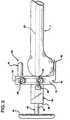
- the positioning apparatusAs shown in detail in Fig. 1, the positioning apparatus, generally indicated at 10, includes a positioning body generally indicated at 12 having sides 13, top surface 14, front surface 15, back surface 19 and cross member 18. Extending from a lower end of the positioning body 12 is positioning tongue 20 having an upper surface 22. Extending into the positioning body 12 from the top surface 14 to the cross member 18 and through the front and back surfaces 15 and 19, is a gap generally defined by slots 16 and partial slot walls 17. Sides 13 include apertures 24 for receiving locking screws 25. Also extending through the body 12 from the back surface 19 to the front surface 15 are apertures 27 for receiving fixation screws 26.
- the positioning apparatus 10receives and holds angular adjustment block generally indicated at 32.
- Angular adjustment block 32includes a front surface 34 having wings 36 sized to be received by the slots 16 in the positioning body 12 to hold the angular adjustment block 32.
- the angular adjustment block 32is locked into place in the positioning body 12 by means of locking screws 25 which extend through apertures 24 in the positioning body 12 and contact the wings 36 of the angular adjustment block 32 to secure the angular adjustment 32 to the positioning body 12.
- the angular adjustment block 32establishes the angular alignment and anterior/posterior location of the positioning apparatus 10.
- the angular adjustment block 32also includes back surface 38 and an aperture 40 extending from the back surface 38 through the angular adjustment block 32 to the front surface 34.
- the aperture 40receives an intramedullary rod 42 therethrough.
- the intramedullary rod 42comprises a shaft 43 and a handle 44.
- the shaft 43extends through the angular adjustment block 32 and into the intramedullary canal which extends along the axis of the femur to aid in establishing the orientation of the resection apparatus of the present invention as hereinafter described.
- the rotational alignment devicegenerally indicated at 50, includes a shaft 51 having a groove 52 therealong and a block 53 having a back surface 54 and wings 56.
- the rotational alignment device 50is interconnected with the positioning body 12 by means of the wings 56 received in slots 16 of the positioning body 12.
- the rotational alignment device 50may be secured to the positioning body 12 by means of locking screws 25 which extend through apertures 24 in the positioning body 12 to contact the wings 56.
- the locking screws 25may be made of various configurations depending upon their specific function. Importantly, the locking screws 25 are used to rigidly affix one component or device to another to ensure that the relative locations and orientations are maintained despite the rigors of surgery.
- the entire positioning apparatus 10is connected to a human femur 7 by means of the shaft 43 of the intramedullary rod 42.
- the shaft 43extends through the angular adjustment block 32, and thereby through the positioning body 12 into the intramedullary canal which extends along the axis of the femur 7.
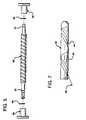
- the intramedullary rod 42shown in Fig. 7, has a groove 41 transversing a helical path 45 along the axis of the shaft 43. The groove 41 relieves intramedullary pressure that leads to fatty embolisms.
- the basic concept of the intramedullary rod 42 with the groove 41is that as it is inserted into the femur, which contains liquid fatty tissue, the liquid fatty tissue is drawn up the groove 41 of the intramedullary rod 42 to draw the fatty liquid tissue out of the femur.
- the intramedullary rodwould have a hexagonal head (not shown), to permit it to be driven by a powered device such as an electrical hand held tool.
- the groove 41does not have a cutting edge, which would risk perforation of the femoral cortex. Accordingly, the device does not cut solid material, but does remove liquid material from the intramedullary canal. Therefore, the risk of fatty embolism is reduced.
- fixation screws 26may be advanced through the apertures 27 in the positioning body 12 until they make contact with the distal femoral condyles of the femur 7, and are then driven into the distal femoral condyles of the femur 7 to initially affix the positioning apparatus to the distal femur 7. It should be noted that the fixation screws 26 may also be advanced and adjusted to make up for deficiencies in the distal femoral condyles. Accordingly, the positioning body 12 is positioned such that the front surface 15 is put into contact with the distal femoral condyles by direct contact and the tongue 20 is positioned under the femur 7 and in contact therewithin.
- the shaft 51 of the rotational alignment device 50extends above the femur 7 and allows for rotation of the pattern device 59, hereinafter described, about the distal femur 7. Additionally, the rotational alignment device 50 allows for the anterior/posterior positioning of the pattern device 59 with respect to the femur 7.
- the configurations of the positioning body 12, the angular adjustment block 32 and the rotational alignment device 50are not limited to the structure set forth herein, but may be of different shapes and may interconnect in different ways. These components may seen be formed as a unitary or partially unitary device.
- the pattern device 59includes pattern plates 60 having tops 61, and cutting paths, generally indicated at 62, extending therethrough.
- the cutting paths 62outline the desired resection shape of the distal femur 7.
- the cutting paths 62could include a first vertical path 64, extending to a first diagonal path 65, extending to a second diagonal path 66, extending to a second vertical path 67, extending to a third diagonal path 68 and then extending to a horizontal path 69.
- the pattern plates 60also include locking screws 75 for interconnecting the pattern plates 60 with crossbar 80.
- the pattern device 59 of the present inventionpreferably includes two pattern plates 60 held in a spaced apart relationship by crossbar 80.
- the crossbar 80separates the pattern plates 60 sufficiently to permit the pattern plates 60 to extend along the sides of the distal femur 7.
- the crossbar 80includes a front surface 82, back surface 84, a top surface 83, a central aperture 86 extending from the front surface 82 to the back surface 84, a lock aperture 88 extending through the top surface 83, and a lock screw 89.
- the central aperture 86 of the crossbar 80receives the shaft 51 of the rotational alignment device 50. Accordingly, the pattern device 59 is interconnected with the positioning apparatus 10 so that the pattern device 59 is properly oriented with respect to the femur 7.
- lock screw 89is extended through lock aperture 88 to contact the shaft 51 to lock the crossbar 80 and, accordingly, the pattern device 59, onto the shaft 51 of the rotational alignment device 50, and accordingly, to positioning apparatus 10.
- This completed assembly, attached to the femur 7,is shown in Fig. 4.
- the pattern plates 60include plate apertures 72 for receiving cannulated screws 70 which have apertures extending therethrough for receiving fixation nails 71 therethrough. Accordingly, after the pattern device 59 is interconnected with the positioning apparatus 10, and properly located and oriented with respect to femur 7, the cannulated screws 70 are extended through the plate aperture 72 to contact the sides of the distal femur 7. Then, in order to fix the pattern plates 60 with respect to the femur 7, the fixation nails 71 are driven into the distal femur 7 to lock the pattern plate 60 into position on the distal femur 7.
- the cannulated screws 70have sharp leading edges for allowing decisive purchase in the distal femur 7 before the introduction of the fixation nails 71 to complete fixation of the pattern device 59 to the distal femur 7.
- the pattern plates 60by virtue of the cutting paths 62, dictate the shape of the resection of the femur 7.
- the cutting paths 62are essentially channels through the pattern plates 60.
- the cutting paths 62receive the cutting device and guide and guide it as it resects the surface of the distal femur 7.
- the pattern plates 60straddle the distal femur 7 mediolaterally and are suspended by the crossbar 80.
- the crossbar 80maintains the proper relationship between the pattern plates 60 before and during the resection of the distal femur 7.
- the location of the crossbar 80 and accordingly, the pattern plates 60may be adjusted with respect to the positioning apparatus 10 by adjusting the position of the block 53 of the rotational alignment device 50 within the slots 16 of the positioning body 12, and locking the same with locking screws 25.
- the cutting paths 62 in the pattern plates 60receive and guide the cutting device shown in Fig. 5 and generally indicated at 90.
- the cutting device 90performs the actual cutting of the femur 7 to resect the femur 7.
- the cutting devicemay be of any known configuration.
- the cutting deviceis a drill.
- the drill 90is generally cylindrical in shape and may possess helical cutting teeth along its length to cut the femur 7.
- the drill 90includes a hexagonal end 95 to permit the use of an electric powered drive, typically an electric drill.
- the drill 90includes drill bushings 92 at the ends of the drill 90 to provide a non-metallic bearing between the cutting paths 62 in the pattern plates 60 to avoid galling and to ensure smooth articulation of the drill 90 along the cutting path 62.
- retention springs 94Positioned between the drill bushings 92 and the drill 90 are retention springs 94 which are essentially coil springs retained within the drill bushings 92 to allow the drill bushings 92 to be easily attached and removed from the drill 90. These retention springs 94 are commercially available in medical grade stainless steels.
- the drill bushings 92retain the retention springs 94 which hold the drill bushings 92 in position 92 on the drill 90 while allowing the drill bushings 92 to rotate freely.
- the drill 90may also include circumferential grooves 91 for allowing attachment and retention of the drill bushings 92 by means of the retention springs 94.
- the configuration of the drill 90can vary in accordance with what is known in the art as long as the cutting device can follow the cutting paths 62 in the pattern plates 60 to resect the femur 7.
- positioning apparatus 10may be removed from connection to the distal femur 7 leaving the pattern device 59 attached to the distal femur 7 to permit resecting of the distal femur.
- the drill 90is then positioned within the cutting paths 62 between the pattern plates 60.
- the drill 90is rotated by power means in connection with the hexagonal end 95, and is then moved along the cutting path 62 to resect the distal femur 7. It should also be noted that the cutting means could be operated by hand.
- pattern plates 60may be employed if it is sufficiently sturdy to support and guide the drill.
- the pattern plates 60may also comprise plates having edges in the shape of the desired distal femoral resection pattern.
- the cutting devicemay be drawn along the edges of the pattern plates to resect the distal femur.
- any cutting device that can be employed to follow the cutting paths in the pattern platesis considered to be within the scope of this invention.
- the resection apparatus of the present inventionprovides extremely accurate and reproducible bone cuts. While the anterior and distal areas of the femur will almost always be able to be prepared in this manner, interference from soft tissue such as fat and ligaments may prohibit satisfactory preparation of the posterior femur. The preparation of any remaining femoral surfaces may be completed in any manner known in the art after using the instrumentation of the present invention.
Landscapes
- Health & Medical Sciences (AREA)
- Surgery (AREA)
- Life Sciences & Earth Sciences (AREA)
- Animal Behavior & Ethology (AREA)
- Public Health (AREA)
- Orthopedic Medicine & Surgery (AREA)
- Oral & Maxillofacial Surgery (AREA)
- Engineering & Computer Science (AREA)
- Biomedical Technology (AREA)
- Heart & Thoracic Surgery (AREA)
- Medical Informatics (AREA)
- Molecular Biology (AREA)
- Dentistry (AREA)
- General Health & Medical Sciences (AREA)
- Nuclear Medicine, Radiotherapy & Molecular Imaging (AREA)
- Veterinary Medicine (AREA)
- Physical Education & Sports Medicine (AREA)
- Transplantation (AREA)
- Surgical Instruments (AREA)
- Harvester Elements (AREA)
- Prostheses (AREA)
- Control Of Amplification And Gain Control (AREA)
- Transmitters (AREA)
- Compounds Of Unknown Constitution (AREA)
Abstract
Description
Preferably, the intramedullary rod would have a hexagonal head (not shown),to permit it to be driven by a powered device such as an electrical hand heldtool. Importantly, the
Claims (15)
- An apparatus for resecting a femur comprising:wherein the cutting means (90) is arranged to coact with the cutting path(62) to follow a required path;positioning means (10) for contacting a femur;support means (50) interconnected with positioning means (10);cutting means (90) for cutting a distal femur;pattern means (59) interconnected with the support means (50), thepattern means comprising at least one pattern plate (60) positionable alongsidea femur; anda cutting path (62) described in the or each pattern plate,
the apparatus beingcharacterised in that the cutting path (62) describedin the or each pattern plate (60) includes a first vertical path (64), extending to afirst diagonal path (65), extending to a second diagonal path (66), extending toa second vertical path (67), extending to a third diagonal path (68) and thenextending to a horizontal path (69), and
in that the cutting means (90) coacts with the cutting path (62) wherebymovement of the cutting means (90) along the cutting path (62) matches aninterior profile of a distal femoral prosthesis. - An apparatus as claimed in Claim 1, further comprising anintramedullary rod (42) insertable into a femur, the intramedullary rodinterconnected with the positioning means (10) to align the positioning meanswith respect to a femur.
- An apparatus as claimed in Claim 2, wherein the intramedullary rod (42)includes at least one groove (41) extending helically along the length of theintramedullary rod.
- An apparatus as claimed in Claim 2 or Claim 3, further comprisingadjustment means (32) for receiving the intramedullary rod, the adjustmentmeans being interconnected with the positioning means (10).
- An apparatus as claimed in Claim 4, wherein the positioning means (10)further comprises a channel (16) extending into the positioning means (10) from an upper surface thereof.
- An apparatus as claimed in Claim 5, wherein the adjustment meansfurther comprises wings (36) sized to be received by the channel (16) in thepositioning means (10).
- An apparatus as claimed in any preceding claim, wherein the cuttingmeans (90) comprises a cylindrical drill extending through the cutting path (62)and movable along the cutting path (62) after the positioning means (10) andthe adjustment means (32) are removed from a femur.
- An apparatus as claimed in any preceding claim, wherein the patternmeans (59) comprises two opposing pattern plates (60) which are spaced apartand extend substantially parallel to one another and are positionable on eitherside of a femur to straddle the femur, wherein the respective cutting paths (62)described in each of the two opposed pattern plates (60) are substantiallyidentical, and wherein the cutting means (90) spans the two pattern plates (60)and coacts with both cutting paths (62).
- An apparatus as claimed in Claim 8, wherein the two pattern plates (60)are held in the spaced apart relationship by a crossbar (80), and wherein acentral aperture (86) of the crossbar receives a shaft (51) of a rotationalalignment device (50) supported by said positioning means (10).
- An apparatus as claimed in any preceding claim, further comprisingfixing means (70,71) for fixing the pattern means (59) to a distal femur.
- An apparatus as claimed in Claim 10, wherein the fixing meanscomprises cannulated screws (70) extended through apertures in the or eachpattern plate (60) and fixation nails (71) extendable through the cannulatedscrews into a distal femur.
- An apparatus as claimed in any preceding claim, wherein the positioningmeans (10) is arranged to position the resecting apparatus on a distal humanfemur, the positioning means having a positioning body (12) comprising:a front surface (15) for contacting a human femur;a tongue (20) extending from a lower end of the positioning body forextending under a human femur;attachment means (26) for attaching the positioning body to a distalhuman femur,the apparatus further comprising:angular adjustment means (32) for adjusting the angle of the positioningmeans (10), the angular adjustment means comprising:an adjustment body (32);a rod (42) extending through the adjustment body and into the distalhuman femur; andattachment means (16,36) for attaching the angular adjustment means(32) to the positioning means (10); andthe apparatus further comprising:rotational alignment means (50) comprising:an alignment body (50);a shaft (51) extending from the alignment body; andattachment means (53,16) for attaching the rotational alignment meansto the positioning means (10).
- An apparatus as claimed in Claim 12, wherein the body (12) of thepositioning means (10) further comprises a channel (16) extending into thepositioning body from a top surface of the positioning body.
- An apparatus as claimed in Claim 13, wherein the body of the angularadjustment means (32) further includes wings (36) sized to be received by thechannel (16) in the body (12) of the positioning means.
- An apparatus as claimed in Claim 13 or Claim 14, wherein the body ofthe rotational alignment means (50) further includes wings (53) sized to bereceived by the channel (16) in the body of the positioning means (10).
Applications Claiming Priority (5)
| Application Number | Priority Date | Filing Date | Title |
|---|---|---|---|
| US479363 | 1983-04-04 | ||
| US300379 | 1994-09-02 | ||
| US08/300,379US5514139A (en) | 1994-09-02 | 1994-09-02 | Method and apparatus for femoral resection |
| US08/479,363US5643272A (en) | 1994-09-02 | 1995-06-07 | Method and apparatus for tibial resection |
| PCT/US1995/011120WO1996007361A1 (en) | 1994-09-02 | 1995-09-01 | Femoral and tibial resection method and apparatus |
Publications (3)
| Publication Number | Publication Date |
|---|---|
| EP0778751A1 EP0778751A1 (en) | 1997-06-18 |
| EP0778751A4 EP0778751A4 (en) | 1997-12-17 |
| EP0778751B1true EP0778751B1 (en) | 2005-05-25 |
Family
ID=26971757
Family Applications (1)
| Application Number | Title | Priority Date | Filing Date |
|---|---|---|---|
| EP95932369AExpired - LifetimeEP0778751B1 (en) | 1994-09-02 | 1995-09-01 | Tibial resection method and apparatus |
Country Status (9)
| Country | Link |
|---|---|
| US (1) | US5643272A (en) |
| EP (1) | EP0778751B1 (en) |
| JP (1) | JPH10507107A (en) |
| KR (1) | KR970705354A (en) |
| AT (1) | ATE296058T1 (en) |
| AU (1) | AU686457B2 (en) |
| CA (1) | CA2198915A1 (en) |
| DE (1) | DE69534232T2 (en) |
| WO (1) | WO1996007361A1 (en) |
Cited By (4)
| Publication number | Priority date | Publication date | Assignee | Title |
|---|---|---|---|---|
| US7520880B2 (en) | 2006-01-09 | 2009-04-21 | Zimmer Technology, Inc. | Adjustable surgical support base with integral hinge |
| US7744600B2 (en) | 2006-01-10 | 2010-06-29 | Zimmer Technology, Inc. | Bone resection guide and method |
| US7993341B2 (en) | 2004-03-08 | 2011-08-09 | Zimmer Technology, Inc. | Navigated orthopaedic guide and method |
| US8114086B2 (en) | 2004-03-08 | 2012-02-14 | Zimmer Technology, Inc. | Navigated cut guide locator |
Families Citing this family (167)
| Publication number | Priority date | Publication date | Assignee | Title |
|---|---|---|---|---|
| US5755803A (en) | 1994-09-02 | 1998-05-26 | Hudson Surgical Design | Prosthetic implant |
| US8603095B2 (en) | 1994-09-02 | 2013-12-10 | Puget Bio Ventures LLC | Apparatuses for femoral and tibial resection |
| US6695848B2 (en) | 1994-09-02 | 2004-02-24 | Hudson Surgical Design, Inc. | Methods for femoral and tibial resection |
| US20020072805A1 (en)* | 1996-08-21 | 2002-06-13 | Sullivan John Martin Patrick | Joint replacement prosthesis |
| AU4036097A (en)* | 1996-08-21 | 1998-03-06 | Industrial Research Limited | A joint replacement prosthesis |
| US5916219A (en)* | 1997-02-10 | 1999-06-29 | Matsuno; Shigeo | Tibial plateau resection guide |
| US6090114A (en)* | 1997-02-10 | 2000-07-18 | Stryker Howmedica Osteonics Corp. | Tibial plateau resection guide |
| US5938665A (en)* | 1997-08-25 | 1999-08-17 | Depuy Orthopaedics, Inc. | Low friction saw slot |
| US7419491B2 (en)* | 1997-09-18 | 2008-09-02 | Medidea, Llc | Bone-conserving orthopedic instrumentation and appliances |
| US6488687B1 (en)* | 1997-09-18 | 2002-12-03 | Medidea, Llc | Joint replacement method and apparatus |
| US5941881A (en)* | 1998-01-09 | 1999-08-24 | Medidea, Llc | Bone fastening apparatus and related procedures |
| US6221035B1 (en)* | 1998-11-16 | 2001-04-24 | Richard J. Kana | Automatic ankle clamp |
| FR2791549B1 (en)* | 1999-04-01 | 2001-05-25 | Aesculap Sa | DEVICE FOR POSITIONING A PROXIMAL END OF A TIBIA RELATIVE TO A CUTTING GUIDE, INCLUDING AN ADJUSTMENT HANDLE |
| US6770078B2 (en) | 2000-01-14 | 2004-08-03 | Peter M. Bonutti | Movable knee implant and methods therefor |
| US7635390B1 (en) | 2000-01-14 | 2009-12-22 | Marctec, Llc | Joint replacement component having a modular articulating surface |
| US7104996B2 (en) | 2000-01-14 | 2006-09-12 | Marctec. Llc | Method of performing surgery |
| US6702821B2 (en) | 2000-01-14 | 2004-03-09 | The Bonutti 2003 Trust A | Instrumentation for minimally invasive joint replacement and methods for using same |
| EP1129677A3 (en)* | 2000-02-29 | 2003-04-02 | Brehm, Peter | Instrumentation for manufacturing the fixation surfaces for a knee joint endoprosthesis |
| AU2005201571B2 (en)* | 2000-03-10 | 2009-01-15 | Smith & Nephew, Inc. | Apparatus for use in arthroplasty of the knees |
| ES2553715T3 (en)* | 2000-03-10 | 2015-12-11 | Smith & Nephew, Inc. | Apparatus for use in arthroplasty in a knee joint |
| US7547307B2 (en) | 2001-02-27 | 2009-06-16 | Smith & Nephew, Inc. | Computer assisted knee arthroplasty instrumentation, systems, and processes |
| US8062377B2 (en) | 2001-03-05 | 2011-11-22 | Hudson Surgical Design, Inc. | Methods and apparatus for knee arthroplasty |
| KR20030002219A (en)* | 2001-06-30 | 2003-01-08 | 한국과학기술원 | Femur clamping robot mount for robotic total hip arthroplasty |
| GB0119540D0 (en)* | 2001-08-10 | 2001-10-03 | Depuy Int Ltd | Tibial resection guide |
| US7708741B1 (en) | 2001-08-28 | 2010-05-04 | Marctec, Llc | Method of preparing bones for knee replacement surgery |
| US7618421B2 (en)* | 2001-10-10 | 2009-11-17 | Howmedica Osteonics Corp. | Tools for femoral resection in knee surgery |
| AU2002348204A1 (en)* | 2001-11-28 | 2003-06-10 | Wright Medical Technology, Inc. | Instrumentation for minimally invasive unicompartmental knee replacement |
| US7141053B2 (en)* | 2001-11-28 | 2006-11-28 | Wright Medical Technology, Inc. | Methods of minimally invasive unicompartmental knee replacement |
| JP2005516724A (en) | 2002-02-11 | 2005-06-09 | スミス アンド ネフュー インコーポレーテッド | Image guided fracture reduction |
| WO2003068119A2 (en)* | 2002-02-14 | 2003-08-21 | Abendschein Walter F | Method and instrumentation for patello-femoral joint replacement |
| EP1480549A4 (en)* | 2002-03-05 | 2010-05-26 | Zimmer Inc | Minimally invasive total knee arthroplasty method and instrumentation |
| US9155544B2 (en) | 2002-03-20 | 2015-10-13 | P Tech, Llc | Robotic systems and methods |
| US20040039395A1 (en)* | 2002-05-24 | 2004-02-26 | Coon Thomas M. | Instruments for knee surgery and method of use |
| US20030236522A1 (en)* | 2002-06-21 | 2003-12-25 | Jack Long | Prosthesis cavity cutting guide, cutting tool and method |
| US7935118B2 (en)* | 2002-06-21 | 2011-05-03 | Depuy Products, Inc. | Prosthesis removal cutting guide, cutting tool and method |
| US7025790B2 (en)* | 2002-06-27 | 2006-04-11 | Concepts In Medicine Iii, L.L.C. | Ankle joint prosthesis and its method of implantation |
| US7628793B2 (en)* | 2002-07-23 | 2009-12-08 | Ortho Development Corporation | Knee balancing block |
| AU2002951548A0 (en)* | 2002-09-19 | 2002-10-03 | Flinders Technologies Pty. Ltd. | Implant clamp and method |
| US7144399B2 (en)* | 2002-10-25 | 2006-12-05 | Zimmer Technology, Inc. | Instrumentation guide for orthopedic surgery |
| US20040097951A1 (en)* | 2002-11-18 | 2004-05-20 | Steffensmeier Scott J. | Measurement instrument for use in orthopaedic surgery |
| US7094241B2 (en) | 2002-11-27 | 2006-08-22 | Zimmer Technology, Inc. | Method and apparatus for achieving correct limb alignment in unicondylar knee arthroplasty |
| US7029477B2 (en)* | 2002-12-20 | 2006-04-18 | Zimmer Technology, Inc. | Surgical instrument and positioning method |
| US20070282347A9 (en)* | 2002-12-20 | 2007-12-06 | Grimm James E | Navigated orthopaedic guide and method |
| US20040172044A1 (en)* | 2002-12-20 | 2004-09-02 | Grimm James E. | Surgical instrument and method of positioning same |
| US7789885B2 (en) | 2003-01-15 | 2010-09-07 | Biomet Manufacturing Corp. | Instrumentation for knee resection |
| US7837690B2 (en) | 2003-01-15 | 2010-11-23 | Biomet Manufacturing Corp. | Method and apparatus for less invasive knee resection |
| US7887542B2 (en) | 2003-01-15 | 2011-02-15 | Biomet Manufacturing Corp. | Method and apparatus for less invasive knee resection |
| US8551100B2 (en) | 2003-01-15 | 2013-10-08 | Biomet Manufacturing, Llc | Instrumentation for knee resection |
| US7241298B2 (en)* | 2003-01-31 | 2007-07-10 | Howmedica Osteonics Corp. | Universal alignment guide |
| US7011664B2 (en)* | 2003-01-31 | 2006-03-14 | Zimmer Technology, Inc. | Resection guide alignment apparatus |
| US7175630B2 (en)* | 2003-02-03 | 2007-02-13 | Zimmer Technology, Inc. | Bone cutting template and method of use |
| US20040153066A1 (en)* | 2003-02-03 | 2004-08-05 | Coon Thomas M. | Apparatus for knee surgery and method of use |
| US20040153087A1 (en)* | 2003-02-04 | 2004-08-05 | Sanford Adam H. | Provisional orthopedic implant with removable guide |
| US6916324B2 (en) | 2003-02-04 | 2005-07-12 | Zimmer Technology, Inc. | Provisional orthopedic prosthesis for partially resected bone |
| US7111401B2 (en)* | 2003-02-04 | 2006-09-26 | Eveready Battery Company, Inc. | Razor head having skin controlling means |
| AU2003901738A0 (en)* | 2003-04-14 | 2003-05-01 | Michael Egan | System for hip revision surgery |
| DE50303568D1 (en)* | 2003-04-25 | 2006-07-06 | Zimmer Gmbh | Device for preparing a femoral condyle |
| EP1470786B1 (en)* | 2003-04-25 | 2005-10-05 | Zimmer GmbH | Device for preparation of a femoral condyle |
| JP4231813B2 (en)* | 2003-05-06 | 2009-03-04 | ツィマー ゲーエムベーハー | Traction equipment |
| US7481814B1 (en) | 2003-07-28 | 2009-01-27 | Biomet Manufacturing Corporation | Method and apparatus for use of a mill or reamer |
| US7534270B2 (en)* | 2003-09-03 | 2009-05-19 | Integra Lifesciences Corporation | Modular total ankle prosthesis apparatuses and methods |
| ATE289787T1 (en)* | 2003-09-15 | 2005-03-15 | Zimmer Gmbh | ADJUSTMENT DEVICE |
| US7862570B2 (en) | 2003-10-03 | 2011-01-04 | Smith & Nephew, Inc. | Surgical positioners |
| US7764985B2 (en) | 2003-10-20 | 2010-07-27 | Smith & Nephew, Inc. | Surgical navigation system component fault interfaces and related processes |
| ATE495706T1 (en) | 2003-11-14 | 2011-02-15 | Smith & Nephew Inc | ADJUSTABLE SURGICAL CUTTING SYSTEMS |
| US7488324B1 (en) | 2003-12-08 | 2009-02-10 | Biomet Manufacturing Corporation | Femoral guide for implanting a femoral knee prosthesis |
| US7641661B2 (en)* | 2003-12-26 | 2010-01-05 | Zimmer Technology, Inc. | Adjustable resection guide |
| US7578824B2 (en)* | 2003-12-30 | 2009-08-25 | Zimmer, Inc. | Methods and apparatus for forming a tunnel through a proximal end of a tibia |
| US20060030854A1 (en) | 2004-02-02 | 2006-02-09 | Haines Timothy G | Methods and apparatus for wireplasty bone resection |
| US7857814B2 (en) | 2004-01-14 | 2010-12-28 | Hudson Surgical Design, Inc. | Methods and apparatus for minimally invasive arthroplasty |
| US9814539B2 (en) | 2004-01-14 | 2017-11-14 | Puget Bioventures Llc | Methods and apparatus for conformable prosthetic implants |
| US7815645B2 (en)* | 2004-01-14 | 2010-10-19 | Hudson Surgical Design, Inc. | Methods and apparatus for pinplasty bone resection |
| US8114083B2 (en) | 2004-01-14 | 2012-02-14 | Hudson Surgical Design, Inc. | Methods and apparatus for improved drilling and milling tools for resection |
| US8021368B2 (en) | 2004-01-14 | 2011-09-20 | Hudson Surgical Design, Inc. | Methods and apparatus for improved cutting tools for resection |
| US20050171545A1 (en)* | 2004-01-30 | 2005-08-04 | Howmedica Osteonics Corp. | Knee computer-aided navigation instruments |
| US7608079B1 (en) | 2004-03-05 | 2009-10-27 | Biomet Manufacturing Corp. | Unicondylar knee apparatus and system |
| CA2561493A1 (en) | 2004-03-31 | 2005-10-20 | Smith & Nephew, Inc. | Methods and apparatuses for providing a reference array input device |
| EP1737375B1 (en) | 2004-04-21 | 2021-08-11 | Smith & Nephew, Inc | Computer-aided navigation systems for shoulder arthroplasty |
| US20070239166A1 (en)* | 2004-05-11 | 2007-10-11 | Mcguire David A | Surgical Device for Anterolateral and Posterolateral Reconstruction |
| US20050261701A1 (en)* | 2004-05-11 | 2005-11-24 | Mcguire David A | Surgical device for a anterolateral reconstruction |
| US7182767B2 (en)* | 2004-05-19 | 2007-02-27 | Howmedica Osteonics Corp. | Navigated lateral/medial femoral resection guide |
| US8167888B2 (en) | 2004-08-06 | 2012-05-01 | Zimmer Technology, Inc. | Tibial spacer blocks and femoral cutting guide |
| EP1809209A2 (en)* | 2004-08-19 | 2007-07-25 | Kinetikos Medical Incorporated | Modular total ankle prosthesis apparatuses, systems and methods, and systems and methods for bone resection and prosthetic implantation |
| US7377924B2 (en)* | 2004-09-09 | 2008-05-27 | Howmedica Osteonics Corp. | Navigated drill guided resection block |
| US7766913B2 (en) | 2004-12-07 | 2010-08-03 | Depuy Products, Inc. | Bone shaping instrument and method for using the same |
| US20060155293A1 (en)* | 2005-01-07 | 2006-07-13 | Zimmer Technology | External rotation cut guide |
| US20060200158A1 (en)* | 2005-01-29 | 2006-09-07 | Farling Toby N | Apparatuses and methods for arthroplastic surgery |
| US8771279B2 (en) | 2005-01-31 | 2014-07-08 | Arthrex, Inc. | Method and apparatus for performing an osteotomy in bone |
| WO2008039269A2 (en)* | 2006-08-02 | 2008-04-03 | Ibalance Medical, Inc. | Method and apparatus for performing an open wedge, high tibial osteotomy |
| US7344542B2 (en)* | 2005-02-18 | 2008-03-18 | Howmedica Osteonics Corp. | Pin extraction assembly |
| WO2006091704A1 (en) | 2005-02-22 | 2006-08-31 | Smith & Nephew, Inc. | In-line milling system |
| US7695479B1 (en) | 2005-04-12 | 2010-04-13 | Biomet Manufacturing Corp. | Femoral sizer |
| US7601154B2 (en)* | 2005-04-18 | 2009-10-13 | Uni-Knee, Llc | Unicondylar knee instrument system |
| FR2885293A1 (en)* | 2005-05-06 | 2006-11-10 | Michel Collette | INSTRUMENT OF VISEEE OF THE FEMEC MECHANICAL AXIS |
| CA2610799C (en)* | 2005-06-03 | 2014-08-05 | Depuy Ireland Limited | Instrument for use in a joint replacement procedure |
| US20070149977A1 (en)* | 2005-11-28 | 2007-06-28 | Zimmer Technology, Inc. | Surgical component positioner |
| US7780671B2 (en)* | 2006-01-23 | 2010-08-24 | Zimmer Technology, Inc. | Bone resection apparatus and method for knee surgery |
| US7662183B2 (en)* | 2006-01-24 | 2010-02-16 | Timothy Haines | Dynamic spinal implants incorporating cartilage bearing graft material |
| US20070186738A1 (en)* | 2006-01-31 | 2007-08-16 | Zimmer Technology, Inc. | Tibial cut guide assembly having rotatable cut guide body |
| US10278711B2 (en) | 2006-02-27 | 2019-05-07 | Biomet Manufacturing, Llc | Patient-specific femoral guide |
| US9289253B2 (en) | 2006-02-27 | 2016-03-22 | Biomet Manufacturing, Llc | Patient-specific shoulder guide |
| US9345548B2 (en) | 2006-02-27 | 2016-05-24 | Biomet Manufacturing, Llc | Patient-specific pre-operative planning |
| US9113971B2 (en) | 2006-02-27 | 2015-08-25 | Biomet Manufacturing, Llc | Femoral acetabular impingement guide |
| US7780672B2 (en) | 2006-02-27 | 2010-08-24 | Biomet Manufacturing Corp. | Femoral adjustment device and associated method |
| US9339278B2 (en) | 2006-02-27 | 2016-05-17 | Biomet Manufacturing, Llc | Patient-specific acetabular guides and associated instruments |
| US8603180B2 (en) | 2006-02-27 | 2013-12-10 | Biomet Manufacturing, Llc | Patient-specific acetabular alignment guides |
| US9907659B2 (en) | 2007-04-17 | 2018-03-06 | Biomet Manufacturing, Llc | Method and apparatus for manufacturing an implant |
| US8407067B2 (en) | 2007-04-17 | 2013-03-26 | Biomet Manufacturing Corp. | Method and apparatus for manufacturing an implant |
| US8591516B2 (en) | 2006-02-27 | 2013-11-26 | Biomet Manufacturing, Llc | Patient-specific orthopedic instruments |
| US20150335438A1 (en) | 2006-02-27 | 2015-11-26 | Biomet Manufacturing, Llc. | Patient-specific augments |
| US9918740B2 (en) | 2006-02-27 | 2018-03-20 | Biomet Manufacturing, Llc | Backup surgical instrument system and method |
| US8070752B2 (en) | 2006-02-27 | 2011-12-06 | Biomet Manufacturing Corp. | Patient specific alignment guide and inter-operative adjustment |
| US9173661B2 (en) | 2006-02-27 | 2015-11-03 | Biomet Manufacturing, Llc | Patient specific alignment guide with cutting surface and laser indicator |
| US7695520B2 (en) | 2006-05-31 | 2010-04-13 | Biomet Manufacturing Corp. | Prosthesis and implementation system |
| US9795399B2 (en) | 2006-06-09 | 2017-10-24 | Biomet Manufacturing, Llc | Patient-specific knee alignment guide and associated method |
| JP5406022B2 (en)* | 2006-06-12 | 2014-02-05 | スミス アンド ネフュー インコーポレーテッド | Tibial resection system, method and apparatus |
| US7678115B2 (en) | 2006-06-21 | 2010-03-16 | Howmedia Osteonics Corp. | Unicondylar knee implants and insertion methods therefor |
| US20080015602A1 (en)* | 2006-06-22 | 2008-01-17 | Howmedica Osteonics Corp. | Cutting block for bone resection |
| US20090234360A1 (en)* | 2006-12-12 | 2009-09-17 | Vladimir Alexander | Laser assisted total joint arthroplasty |
| JP5362581B2 (en)* | 2006-12-15 | 2013-12-11 | ジンテス ゲゼルシャフト ミット ベシュレンクテル ハフツング | Radiation guide and method for cutting the inner distal part of the tibia using this guide |
| US8147497B2 (en)* | 2007-03-02 | 2012-04-03 | Greatbatch Medical S.A. | In situ patellar fixing system |
| KR100906093B1 (en)* | 2007-07-25 | 2009-07-06 | 주식회사 사이버메드 | Bone cutting guide |
| US20100198354A1 (en) | 2007-08-01 | 2010-08-05 | Jeffrey Halbrecht | Method and system for patella tendon realignment |
| US8265949B2 (en) | 2007-09-27 | 2012-09-11 | Depuy Products, Inc. | Customized patient surgical plan |
| US8357111B2 (en) | 2007-09-30 | 2013-01-22 | Depuy Products, Inc. | Method and system for designing patient-specific orthopaedic surgical instruments |
| EP2194889B1 (en) | 2007-09-30 | 2015-09-23 | DePuy Products, Inc. | Customized patient-specific orthopaedic surgical instrumentation |
| EP2135566B1 (en)* | 2008-06-20 | 2011-03-09 | Arthrex, Inc. | Latarjet instrumentation |
| US8197489B2 (en)* | 2008-06-27 | 2012-06-12 | Depuy Products, Inc. | Knee ligament balancer |
| US8808303B2 (en)* | 2009-02-24 | 2014-08-19 | Microport Orthopedics Holdings Inc. | Orthopedic surgical guide |
| US8556830B2 (en) | 2009-03-31 | 2013-10-15 | Depuy | Device and method for displaying joint force data |
| US8597210B2 (en) | 2009-03-31 | 2013-12-03 | Depuy (Ireland) | System and method for displaying joint force data |
| US8551023B2 (en) | 2009-03-31 | 2013-10-08 | Depuy (Ireland) | Device and method for determining force of a knee joint |
| US8740817B2 (en) | 2009-03-31 | 2014-06-03 | Depuy (Ireland) | Device and method for determining forces of a patient's joint |
| US8721568B2 (en) | 2009-03-31 | 2014-05-13 | Depuy (Ireland) | Method for performing an orthopaedic surgical procedure |
| KR101973101B1 (en) | 2009-05-29 | 2019-04-26 | 스미스 앤드 네퓨, 인크. | Methods and apparatus for performing knee arthroplasty |
| US8900316B2 (en) | 2010-01-29 | 2014-12-02 | Smith & Nephew, Inc. | Cruciate-retaining knee prosthesis |
| GB2480846B (en)* | 2010-06-03 | 2017-04-19 | Biomet Uk Healthcare Ltd | Guiding tool |
| US8747410B2 (en) | 2010-10-26 | 2014-06-10 | Zimmer, Inc. | Patellar resection instrument with variable depth guide |
| US9968376B2 (en) | 2010-11-29 | 2018-05-15 | Biomet Manufacturing, Llc | Patient-specific orthopedic instruments |
| US9241745B2 (en) | 2011-03-07 | 2016-01-26 | Biomet Manufacturing, Llc | Patient-specific femoral version guide |
| US8951301B2 (en) | 2011-06-30 | 2015-02-10 | Depuy (Ireland) | Method of using a trialing system for a knee prosthesis |
| US8926619B2 (en) | 2011-06-30 | 2015-01-06 | Depuy (Ireland) | Method of surgically preparing a tibia for implantation of a prosthetic component |
| US8986390B2 (en) | 2011-06-30 | 2015-03-24 | Depuy (Ireland) | Method of trialing a knee prosthesis |
| US20130006378A1 (en) | 2011-06-30 | 2013-01-03 | Wogoman Thomas E | Polymer femoral trial component |
| US8968412B2 (en) | 2011-06-30 | 2015-03-03 | Depuy (Ireland) | Trialing system for a knee prosthesis and method of use |
| US8939986B2 (en) | 2011-06-30 | 2015-01-27 | Depuy (Ireland) | Surgical instruments for use in surgically preparing a tibia for implantation of a prosthetic component |
| US8852197B2 (en) | 2011-06-30 | 2014-10-07 | Depuy (Ireland) | Surgical instrument assemblies for use in surgically preparing a tibia for implantation of a prosthetic component |
| EP2561814A1 (en)* | 2011-08-25 | 2013-02-27 | Deru GmbH | Cutting guide for creating an external contour for an articulated endoprosthetic |
| GB201115411D0 (en) | 2011-09-07 | 2011-10-19 | Depuy Ireland | Surgical instrument |
| US9381011B2 (en) | 2012-03-29 | 2016-07-05 | Depuy (Ireland) | Orthopedic surgical instrument for knee surgery |
| US10098761B2 (en) | 2012-03-31 | 2018-10-16 | DePuy Synthes Products, Inc. | System and method for validating an orthopaedic surgical plan |
| US10206792B2 (en) | 2012-03-31 | 2019-02-19 | Depuy Ireland Unlimited Company | Orthopaedic surgical system for determining joint forces of a patients knee joint |
| US10070973B2 (en) | 2012-03-31 | 2018-09-11 | Depuy Ireland Unlimited Company | Orthopaedic sensor module and system for determining joint forces of a patient's knee joint |
| US9545459B2 (en) | 2012-03-31 | 2017-01-17 | Depuy Ireland Unlimited Company | Container for surgical instruments and system including same |
| US9060786B2 (en) | 2013-08-15 | 2015-06-23 | Biomet Manufacturing, Llc | X-ray based cut block positioning jig |
| US9861491B2 (en) | 2014-04-30 | 2018-01-09 | Depuy Ireland Unlimited Company | Tibial trial system for a knee prosthesis |
| US20180085152A1 (en)* | 2014-10-24 | 2018-03-29 | Firoozeh Madadi | Intertrochanteric fixation device |
| US10973529B2 (en) | 2015-04-16 | 2021-04-13 | Minmaxmedical | Patient-specific surgical guide |
| US10195056B2 (en) | 2015-10-19 | 2019-02-05 | Depuy Ireland Unlimited Company | Method for preparing a patient's tibia to receive an implant |
| US10537445B2 (en) | 2015-10-19 | 2020-01-21 | Depuy Ireland Unlimited Company | Surgical instruments for preparing a patient's tibia to receive an implant |
| US10058393B2 (en) | 2015-10-21 | 2018-08-28 | P Tech, Llc | Systems and methods for navigation and visualization |
| US10722310B2 (en) | 2017-03-13 | 2020-07-28 | Zimmer Biomet CMF and Thoracic, LLC | Virtual surgery planning system and method |
| KR102157064B1 (en)* | 2018-06-08 | 2020-09-18 | 조선대학교산학협력단 | Costal cartilage harvester |
| US11051829B2 (en) | 2018-06-26 | 2021-07-06 | DePuy Synthes Products, Inc. | Customized patient-specific orthopaedic surgical instrument |
| US11896476B2 (en) | 2020-01-02 | 2024-02-13 | Zkr Orthopedics, Inc. | Patella tendon realignment implant with changeable shape |
| US11684377B2 (en)* | 2020-01-22 | 2023-06-27 | Howmedica Osteonics Corp. | Joint resection guide |
| WO2021231253A1 (en) | 2020-05-11 | 2021-11-18 | Zkr Orthopedics, Inc. | Adjustable patellar tendon realignment implant |
Family Cites Families (24)
| Publication number | Priority date | Publication date | Assignee | Title |
|---|---|---|---|---|
| US4487203A (en)* | 1981-11-03 | 1984-12-11 | Androphy Gary W | Triplanar knee resection method |
| US4524766A (en)* | 1982-01-07 | 1985-06-25 | Petersen Thomas D | Surgical knee alignment method and system |
| US4653488A (en)* | 1982-02-18 | 1987-03-31 | Howmedica, Inc. | Prosthetic knee implantation |
| US4457307A (en)* | 1982-08-20 | 1984-07-03 | Stillwell William T | Bone cutting device for total knee replacement |
| US4566448A (en)* | 1983-03-07 | 1986-01-28 | Rohr Jr William L | Ligament tensor and distal femoral resector guide |
| US4787383A (en)* | 1985-12-19 | 1988-11-29 | Howmedica, Inc. | Prosthetic knee implantation |
| US4736737A (en)* | 1986-03-31 | 1988-04-12 | William Fargie | Tibial cutting jig |
| US4722330A (en)* | 1986-04-22 | 1988-02-02 | Dow Corning Wright Corporation | Femoral surface shaping guide for knee implants |
| US5250050A (en)* | 1987-02-07 | 1993-10-05 | Pfizer Hospital Products Group, Inc. | Apparatus for knee prosthesis |
| US4938762A (en)* | 1987-12-16 | 1990-07-03 | Protek Ag | Reference system for implantation of condylar total knee prostheses |
| US5002545A (en)* | 1989-01-30 | 1991-03-26 | Dow Corning Wright Corporation | Tibial surface shaping guide for knee implants |
| US4952213A (en)* | 1989-02-03 | 1990-08-28 | Boehringer Mannheim Corporation | Tibial cutting guide |
| US5171244A (en)* | 1990-01-08 | 1992-12-15 | Caspari Richard B | Methods and apparatus for arthroscopic prosthetic knee replacement |
| IT1248971B (en)* | 1990-06-22 | 1995-02-11 | Cremascoli G Srl | EQUIPMENT SUITABLE TO ALLOW THE PERFORMANCE OF A CORRECT FEMORAL AND TIBIAL RESECTION FOR THE APPLICATION OF REPLACEMENT PROSTHESES OF THE KNEE JOINT |
| FR2664157B1 (en)* | 1990-07-06 | 1992-10-30 | Jbs Sa | FEMORAL CUTTING GUIDE. |
| US5180384A (en)* | 1991-02-08 | 1993-01-19 | Mikhail Michael W E | Method for implanting a patellar prosthesis |
| US5053037A (en)* | 1991-03-07 | 1991-10-01 | Smith & Nephew Richards Inc. | Femoral instrumentation for long stem surgery |
| US5147365A (en)* | 1991-08-19 | 1992-09-15 | Intermedics Orthopedics, Inc. | Patellar osteotomy guide |
| FR2681778B1 (en)* | 1991-10-01 | 1997-11-28 | Impact | MODULAR ANCILLARY FOR THE PLACEMENT OF A KNEE PROSTHESIS. |
| EP0551572B1 (en)* | 1991-12-10 | 1998-12-30 | Bristol-Myers Squibb Company | Tibial resector guide |
| US5269786A (en)* | 1992-02-20 | 1993-12-14 | Arthrex Inc. | PCL oriented placement tibial guide method |
| US5342368A (en)* | 1992-07-08 | 1994-08-30 | Petersen Thomas D | Intramedullary universal proximal tibial resector guide |
| US5908424A (en)* | 1994-05-16 | 1999-06-01 | Zimmer, Inc, By Said Stalcup, Dietz, Bays And Vanlaningham | Tibial milling guide system |
| FR2722392A1 (en)* | 1994-07-12 | 1996-01-19 | Biomicron | APPARATUS FOR RESECTING KNEE CONDYLES FOR PLACING A PROSTHESIS AND METHOD FOR PLACING SUCH AN APPARATUS |
- 1995
- 1995-06-07USUS08/479,363patent/US5643272A/ennot_activeExpired - Lifetime
- 1995-09-01CACA002198915Apatent/CA2198915A1/ennot_activeAbandoned
- 1995-09-01WOPCT/US1995/011120patent/WO1996007361A1/enactiveIP Right Grant
- 1995-09-01ATAT95932369Tpatent/ATE296058T1/ennot_activeIP Right Cessation
- 1995-09-01KRKR1019970701296Apatent/KR970705354A/ennot_activeWithdrawn
- 1995-09-01AUAU35432/95Apatent/AU686457B2/ennot_activeCeased
- 1995-09-01JPJP8509591Apatent/JPH10507107A/enactivePending
- 1995-09-01DEDE69534232Tpatent/DE69534232T2/ennot_activeExpired - Fee Related
- 1995-09-01EPEP95932369Apatent/EP0778751B1/ennot_activeExpired - Lifetime
Cited By (4)
| Publication number | Priority date | Publication date | Assignee | Title |
|---|---|---|---|---|
| US7993341B2 (en) | 2004-03-08 | 2011-08-09 | Zimmer Technology, Inc. | Navigated orthopaedic guide and method |
| US8114086B2 (en) | 2004-03-08 | 2012-02-14 | Zimmer Technology, Inc. | Navigated cut guide locator |
| US7520880B2 (en) | 2006-01-09 | 2009-04-21 | Zimmer Technology, Inc. | Adjustable surgical support base with integral hinge |
| US7744600B2 (en) | 2006-01-10 | 2010-06-29 | Zimmer Technology, Inc. | Bone resection guide and method |
Also Published As
| Publication number | Publication date |
|---|---|
| US5643272A (en) | 1997-07-01 |
| ATE296058T1 (en) | 2005-06-15 |
| AU686457B2 (en) | 1998-02-05 |
| DE69534232T2 (en) | 2006-01-19 |
| EP0778751A1 (en) | 1997-06-18 |
| DE69534232D1 (en) | 2005-06-30 |
| EP0778751A4 (en) | 1997-12-17 |
| CA2198915A1 (en) | 1996-03-14 |
| AU3543295A (en) | 1996-03-27 |
| WO1996007361A1 (en) | 1996-03-14 |
| KR970705354A (en) | 1997-10-09 |
| JPH10507107A (en) | 1998-07-14 |
Similar Documents
| Publication | Publication Date | Title |
|---|---|---|
| EP0778751B1 (en) | Tibial resection method and apparatus | |
| US5514139A (en) | Method and apparatus for femoral resection | |
| US6858032B2 (en) | Rotating track cutting guide system | |
| CA1211331A (en) | Method and apparatus for shaping a distal femoral surface | |
| US5597379A (en) | Method and apparatus for femoral resection alignment | |
| JP2591893B2 (en) | Rotation and angle adjustable tibial cutting guide and method of use | |
| US6056754A (en) | Method and apparatus for patella resection and guide handle | |
| US5997543A (en) | Surgical instrumentation | |
| US9421022B2 (en) | Method and apparatus for total knee arthroplasty | |
| US5520695A (en) | Instruments for use in knee replacement surgery | |
| US6852115B2 (en) | Multi-functional orthopedic surgical instrument and method of using same | |
| US7967822B2 (en) | Methods and apparatus for orthopedic implants | |
| US5304181A (en) | Methods and apparatus for arthroscopic prosthetic knee replacement | |
| KR100430362B1 (en) | Tibial resection instrument | |
| US20120053591A1 (en) | Apparatuses for femoral and tibial resection | |
| US20040220578A1 (en) | Bone instruments and methods | |
| JP2004130109A (en) | Foot joint fixation guide and method therefor | |
| WO1997030640A1 (en) | Distal femoral cutting guide apparatus | |
| NZ205096A (en) | Mounting apparatus for bone cutting device | |
| KR19980702248A (en) | Distal Femoral Cut Guide | |
| WO1997029697A1 (en) | Distal femoral cutting block assembly | |
| JP2000501633A (en) | Equipment for distal thigh size measurement and anterior and distal femoral resection | |
| IE83815B1 (en) | Surgical instrumentation |
Legal Events
| Date | Code | Title | Description |
|---|---|---|---|
| PUAI | Public reference made under article 153(3) epc to a published international application that has entered the european phase | Free format text:ORIGINAL CODE: 0009012 | |
| 17P | Request for examination filed | Effective date:19970228 | |
| AK | Designated contracting states | Kind code of ref document:A1 Designated state(s):AT BE DE FR GB IT NL SE | |
| A4 | Supplementary search report drawn up and despatched | Effective date:19971029 | |
| AK | Designated contracting states | Kind code of ref document:A4 Designated state(s):AT BE DE FR GB IT NL SE | |
| 17Q | First examination report despatched | Effective date:20000811 | |
| RTI1 | Title (correction) | Free format text:TIBIAL RESECTION METHOD AND APPARATUS | |
| GRAP | Despatch of communication of intention to grant a patent | Free format text:ORIGINAL CODE: EPIDOSNIGR1 | |
| GRAS | Grant fee paid | Free format text:ORIGINAL CODE: EPIDOSNIGR3 | |
| GRAA | (expected) grant | Free format text:ORIGINAL CODE: 0009210 | |
| AK | Designated contracting states | Kind code of ref document:B1 Designated state(s):AT BE DE FR GB IT NL SE | |
| PG25 | Lapsed in a contracting state [announced via postgrant information from national office to epo] | Ref country code:NL Free format text:LAPSE BECAUSE OF FAILURE TO SUBMIT A TRANSLATION OF THE DESCRIPTION OR TO PAY THE FEE WITHIN THE PRESCRIBED TIME-LIMIT Effective date:20050525 Ref country code:IT Free format text:LAPSE BECAUSE OF FAILURE TO SUBMIT A TRANSLATION OF THE DESCRIPTION OR TO PAY THE FEE WITHIN THE PRESCRIBED TIME-LIMIT;WARNING: LAPSES OF ITALIAN PATENTS WITH EFFECTIVE DATE BEFORE 2007 MAY HAVE OCCURRED AT ANY TIME BEFORE 2007. THE CORRECT EFFECTIVE DATE MAY BE DIFFERENT FROM THE ONE RECORDED. Effective date:20050525 Ref country code:BE Free format text:LAPSE BECAUSE OF FAILURE TO SUBMIT A TRANSLATION OF THE DESCRIPTION OR TO PAY THE FEE WITHIN THE PRESCRIBED TIME-LIMIT Effective date:20050525 Ref country code:AT Free format text:LAPSE BECAUSE OF FAILURE TO SUBMIT A TRANSLATION OF THE DESCRIPTION OR TO PAY THE FEE WITHIN THE PRESCRIBED TIME-LIMIT Effective date:20050525 | |
| REG | Reference to a national code | Ref country code:GB Ref legal event code:FG4D | |
| REF | Corresponds to: | Ref document number:69534232 Country of ref document:DE Date of ref document:20050630 Kind code of ref document:P | |
| PG25 | Lapsed in a contracting state [announced via postgrant information from national office to epo] | Ref country code:SE Free format text:LAPSE BECAUSE OF FAILURE TO SUBMIT A TRANSLATION OF THE DESCRIPTION OR TO PAY THE FEE WITHIN THE PRESCRIBED TIME-LIMIT Effective date:20050825 | |
| PG25 | Lapsed in a contracting state [announced via postgrant information from national office to epo] | Ref country code:GB Free format text:LAPSE BECAUSE OF NON-PAYMENT OF DUE FEES Effective date:20050901 | |
| NLV1 | Nl: lapsed or annulled due to failure to fulfill the requirements of art. 29p and 29m of the patents act | ||
| PLBE | No opposition filed within time limit | Free format text:ORIGINAL CODE: 0009261 | |
| STAA | Information on the status of an ep patent application or granted ep patent | Free format text:STATUS: NO OPPOSITION FILED WITHIN TIME LIMIT | |
| PG25 | Lapsed in a contracting state [announced via postgrant information from national office to epo] | Ref country code:DE Free format text:LAPSE BECAUSE OF NON-PAYMENT OF DUE FEES Effective date:20060401 | |
| ET | Fr: translation filed | ||
| 26N | No opposition filed | Effective date:20060228 | |
| GBPC | Gb: european patent ceased through non-payment of renewal fee | Effective date:20050901 | |
| REG | Reference to a national code | Ref country code:FR Ref legal event code:ST Effective date:20080229 | |
| PG25 | Lapsed in a contracting state [announced via postgrant information from national office to epo] | Ref country code:FR Free format text:LAPSE BECAUSE OF NON-PAYMENT OF DUE FEES Effective date:20050930 |