EP0774237B1 - Apparatus for vascular hole closure - Google Patents
Apparatus for vascular hole closureDownload PDFInfo
- Publication number
- EP0774237B1 EP0774237B1EP96116909AEP96116909AEP0774237B1EP 0774237 B1EP0774237 B1EP 0774237B1EP 96116909 AEP96116909 AEP 96116909AEP 96116909 AEP96116909 AEP 96116909AEP 0774237 B1EP0774237 B1EP 0774237B1
- Authority
- EP
- European Patent Office
- Prior art keywords
- movement
- distal
- locator
- handle
- elongate body
- Prior art date
- Legal status (The legal status is an assumption and is not a legal conclusion. Google has not performed a legal analysis and makes no representation as to the accuracy of the status listed.)
- Expired - Lifetime
Links
- 230000002792vascularEffects0.000titledescription5
- 210000004204blood vesselAnatomy0.000claimsdescription40
- 239000000463materialSubstances0.000claimsdescription6
- 230000000295complement effectEffects0.000claimsdescription4
- 230000004044responseEffects0.000claimsdescription3
- 238000000034methodMethods0.000description26
- 230000008878couplingEffects0.000description9
- 238000010168coupling processMethods0.000description9
- 238000005859coupling reactionMethods0.000description9
- 238000001356surgical procedureMethods0.000description3
- 102000008186CollagenHuman genes0.000description2
- 108010035532CollagenProteins0.000description2
- PXHVJJICTQNCMI-UHFFFAOYSA-NNickelChemical group[Ni]PXHVJJICTQNCMI-UHFFFAOYSA-N0.000description2
- RTAQQCXQSZGOHL-UHFFFAOYSA-NTitaniumChemical compound[Ti]RTAQQCXQSZGOHL-UHFFFAOYSA-N0.000description2
- 238000002583angiographyMethods0.000description2
- 238000002399angioplastyMethods0.000description2
- 239000008280bloodSubstances0.000description2
- 210000004369bloodAnatomy0.000description2
- 229920001436collagenPolymers0.000description2
- 238000010276constructionMethods0.000description2
- 230000000694effectsEffects0.000description2
- 230000014759maintenance of locationEffects0.000description2
- 230000008439repair processEffects0.000description2
- 239000010936titaniumSubstances0.000description2
- 229910052719titaniumInorganic materials0.000description2
- 206010053567CoagulopathiesDiseases0.000description1
- 206010020772HypertensionDiseases0.000description1
- 206010061216InfarctionDiseases0.000description1
- 208000007536ThrombosisDiseases0.000description1
- 239000000956alloySubstances0.000description1
- 229910045601alloyInorganic materials0.000description1
- 229940127090anticoagulant agentDrugs0.000description1
- 229940030225antihemorrhagicsDrugs0.000description1
- 238000013459approachMethods0.000description1
- 230000008901benefitEffects0.000description1
- 239000000560biocompatible materialSubstances0.000description1
- 230000017531blood circulationEffects0.000description1
- 210000001124body fluidAnatomy0.000description1
- 239000010839body fluidSubstances0.000description1
- 230000035602clottingEffects0.000description1
- 230000003247decreasing effectEffects0.000description1
- 230000001419dependent effectEffects0.000description1
- 230000008021depositionEffects0.000description1
- -1for exampleSubstances0.000description1
- 230000035876healingEffects0.000description1
- 230000023597hemostasisEffects0.000description1
- 239000002874hemostatic agentSubstances0.000description1
- 230000001631hypertensive effectEffects0.000description1
- 230000007574infarctionEffects0.000description1
- 230000003993interactionEffects0.000description1
- 239000000203mixtureSubstances0.000description1
- 229910052759nickelInorganic materials0.000description1
- 239000002245particleSubstances0.000description1
- 229920000642polymerPolymers0.000description1
- 239000012858resilient materialSubstances0.000description1
- 208000010110spontaneous platelet aggregationDiseases0.000description1
- 239000010935stainless steelSubstances0.000description1
- 229910001220stainless steelInorganic materials0.000description1
- 239000000126substanceSubstances0.000description1
- 229910052715tantalumInorganic materials0.000description1
- GUVRBAGPIYLISA-UHFFFAOYSA-Ntantalum atomChemical compound[Ta]GUVRBAGPIYLISA-UHFFFAOYSA-N0.000description1
- 230000003966vascular damageEffects0.000description1
- 238000007631vascular surgeryMethods0.000description1
Images


Classifications
- A—HUMAN NECESSITIES
- A61—MEDICAL OR VETERINARY SCIENCE; HYGIENE
- A61B—DIAGNOSIS; SURGERY; IDENTIFICATION
- A61B17/00—Surgical instruments, devices or methods
- A61B17/12—Surgical instruments, devices or methods for ligaturing or otherwise compressing tubular parts of the body, e.g. blood vessels or umbilical cord
- A61B17/122—Clamps or clips, e.g. for the umbilical cord
- A61B17/1227—Spring clips
- A—HUMAN NECESSITIES
- A61—MEDICAL OR VETERINARY SCIENCE; HYGIENE
- A61B—DIAGNOSIS; SURGERY; IDENTIFICATION
- A61B17/00—Surgical instruments, devices or methods
- A61B17/0057—Implements for plugging an opening in the wall of a hollow or tubular organ, e.g. for sealing a vessel puncture or closing a cardiac septal defect
- A—HUMAN NECESSITIES
- A61—MEDICAL OR VETERINARY SCIENCE; HYGIENE
- A61B—DIAGNOSIS; SURGERY; IDENTIFICATION
- A61B17/00—Surgical instruments, devices or methods
- A61B17/12—Surgical instruments, devices or methods for ligaturing or otherwise compressing tubular parts of the body, e.g. blood vessels or umbilical cord
- A61B17/128—Surgical instruments, devices or methods for ligaturing or otherwise compressing tubular parts of the body, e.g. blood vessels or umbilical cord for applying or removing clamps or clips
- A61B17/1285—Surgical instruments, devices or methods for ligaturing or otherwise compressing tubular parts of the body, e.g. blood vessels or umbilical cord for applying or removing clamps or clips for minimally invasive surgery
- A—HUMAN NECESSITIES
- A61—MEDICAL OR VETERINARY SCIENCE; HYGIENE
- A61B—DIAGNOSIS; SURGERY; IDENTIFICATION
- A61B17/00—Surgical instruments, devices or methods
- A61B17/00234—Surgical instruments, devices or methods for minimally invasive surgery
- A—HUMAN NECESSITIES
- A61—MEDICAL OR VETERINARY SCIENCE; HYGIENE
- A61B—DIAGNOSIS; SURGERY; IDENTIFICATION
- A61B17/00—Surgical instruments, devices or methods
- A61B17/0057—Implements for plugging an opening in the wall of a hollow or tubular organ, e.g. for sealing a vessel puncture or closing a cardiac septal defect
- A61B2017/00637—Implements for plugging an opening in the wall of a hollow or tubular organ, e.g. for sealing a vessel puncture or closing a cardiac septal defect for sealing trocar wounds through abdominal wall
- A—HUMAN NECESSITIES
- A61—MEDICAL OR VETERINARY SCIENCE; HYGIENE
- A61B—DIAGNOSIS; SURGERY; IDENTIFICATION
- A61B17/00—Surgical instruments, devices or methods
- A61B17/0057—Implements for plugging an opening in the wall of a hollow or tubular organ, e.g. for sealing a vessel puncture or closing a cardiac septal defect
- A61B2017/00646—Type of implements
- A61B2017/00668—Type of implements the implement being a tack or a staple
- A—HUMAN NECESSITIES
- A61—MEDICAL OR VETERINARY SCIENCE; HYGIENE
- A61B—DIAGNOSIS; SURGERY; IDENTIFICATION
- A61B17/00—Surgical instruments, devices or methods
- A61B17/0057—Implements for plugging an opening in the wall of a hollow or tubular organ, e.g. for sealing a vessel puncture or closing a cardiac septal defect
- A61B2017/00672—Locating means therefor, e.g. bleed back lumen
Definitions
- the present disclosurerelates to an apparatus for closing a hole or puncture in a blood vessel, and more particularly, to an apparatus for applying a surgical clip to a blood vessel to close a hole formed therein during an intravascular catheterization procedure.
- Apparatus to deploy a surgical closure to close a hole in a blood vessel wallin accordance with the pre-characterising part of claim 1 below, is disclosed in US-A-5-342 393.
- a sharpened hollow needleis first percutaneously introduced into the vascular system.
- a guide wireis then inserted through the hollow needle and into the lumen of a selected blood vessel.
- the needleis removed and a dilator and/or introducer is fed into the vessel along the guide wire.
- the guide wireis then removed and a suitable catheter is fed through the lumen of the introducer and advanced through the vascular system until the working end thereof is positioned at the operating site.
- the catheteris withdrawn, and subsequently, the dilator and/or introducer is also removed from the wound.
- the vessel puncturemust be sealed in order to stem the flow of blood therethrough. Because it is often common practice to administer a blood thinning agent to the patient prior to the catheterization procedures, stemming the blood flow can be troublesome. A common method of healing the wound is to maintain external pressure over the vessel until the puncture naturally seals. This method of puncture closure typically takes about thirty minutes, with the length of time usually being greater if the patient is hypertensive or anti-coagulated. When hand pressure is utilized, it can be uncomfortable for the patient and can use costly professional time on the part of the hospital staff. Other pressure application techniques, such as pressure bandages, sandbags or clamps, have been employed, but these devices also require the patient to remain motionless for an extended period of time and the patient must be closely monitored to ensure their effectiveness.
- Surgical clips and clip appliersare known and have been used in vascular surgery, particularly to join severed vessels. See, for example, U.S. Patent No. 4,929,240 (Kirsch, et al.).
- the clips disclosed in the '240 Patentprovide an advantage over suturing by decreasing the likelihood of clotting and vascular damage, particularly in micro-vascular repair procedures. While vascular clips have been successfully used in surgery, the surgical procedures in which the clips are used typically allow the surgeon to view the area to be clipped. In catheter puncture repair procedures, however, the wound is generally not visible, making proper clip application, if attempted, difficult.
- the present inventionis defined in claim 1 below.
- Dependent claimsare directed to optional or preferred features.
- the subject applicationdescribes apparatus and method for applying a surgical clip to an exterior wall of a blood vessel to at least partially close a hole formed therein during a catheterization procedure.
- the apparatusincludes a handle portion, an elongate body extending distally from the handle portion and dimensioned to extend through a hole in the wall of a blood vessel, and a collapsible locator operatively associated with the elongate body and mounted for movement between a collapsed retracted position disposed within a distal end portion of the elongate body and an expanded deployed position extending from the distal end portion of the elongate body.
- the locatorforms, in its deployed position, a locator loop and is adapted and configured to expand within an interior lumen of the blood vessel in the deployed position to maintain the distal end portion of the elongated body in a desired location with respect to the hole in blood vessel wall.
- a surgical clipis releasably supported adjacent the distal end portion of the elongate body which is configured for application to the exterior wall of the blood vessel to at least partially close the hole formed therein when the locator is substantially in the deployed position.
- the surgical cliphas a pair of opposed clip legs connected by a bail portion, and the bail portion has an aperture provided therein to accommodate movement of the locator from the deployed position to the retracted position upon application of the clip to the exterior wall of the blood vessel.
- a control rodmay extend from the handle portion through the elongate body and may be mounted for movement between a proximal position and a distal position to effectuate the movement of the collapsible locator between the retracted position and the deployed position, and a control knob may be operatively mounted to a proximal end of the control rod to facilitate the longitudinal movement thereof.
- the control knobpreferably includes means for releasably engaging the handle portion when the collapsible locator is disposed in the deployed position.
- the elongate bodyincludes an outer tubular member mounted for axial movement with respect to the handle portion between a proximal position and a distal position, and structure is provided adjacent a distal end of the elongate body for releasably supporting the surgical clip.
- a pair of diametrically opposed camming rampsare preferably formed adjacent a distal end of the elongate body, distal of the clip support structure, to cause the opposed legs of the surgical clip to move between a closed position and an open position in response to longitudinal movement of the outer tubular member from the distal position toward the proximal position.
- An actuation handleis operatively associated with the handle portion of the surgical apparatus and is mounted for manipulation through an actuating stroke.
- movement of the actuation handle through a first segment of the actuating strokecauses the outer tubular member to move from the proximal position to the distal position
- movement of the actuation handle through a second segment of the actuating strokecauses the actuation rod to move from the distal position to the proximal position.
- movement of the actuation handle through the second segment of the actuating strokereleases the control knob from an engaged position.
- distal and proximal actuating membersare supported within the handle portion and are operatively connected to the actuation handle.
- a first control linkconnects the distal actuating member to the actuation handle and second control link connects the proximal actuating member to the actuation handle.
- the distal actuating memberis also connected to a proximal end of the outer tubular member, and the proximal actuating member is also connected to a release tube which is dimensioned to interact with the control knob upon movement of the actuation handle through the second segment of the actuating stroke.
- the method disclosedincludes the steps of taking an elongate body having a surgical clip supported adjacent a distal end portion thereof, extending the elongate body through the hole in the blood vessel such that at least a distal end portion thereof projects into an interior lumen of the blood vessel, and deploying a locator from the distal end portion of the elongate body into the interior lumen of the blood vessel to maintain the elongate body in a desired position with respect to the hole in the wall of the blood vessel.
- the methodfurther includes the steps of applying the surgical clip to the exterior wall of the blood vessel to at least partially close the hole therein, and retracting the locator from the interior lumen of the blood vessel.
- the method step of applying the surgical clipcan include the step advancing the surgical clip in a distal direction from a proximal support position on the elongate body, and the step of moving the surgical clip between open and closed positions.
- the step of deploying the locatorincludes the step of moving the locator from a collapsed position within the distal end position of the elongate body to an expanded position extending from the distal end portion of the body.
- the step of withdrawing the locatoris concomitant with the step of applying the surgical clip to the exterior wall of the blood vessel.
- proximalas is traditional, will refer to the end of the apparatus which is closest to the operator, while the term “distal” will refer to the end of the apparatus which is furthest from the operator.
- Surgical apparatus 10is adapted and configured to apply a surgical clip to the exterior wall of a blood vessel to at least partially close a hole formed therein during a catheterization procedure, such as, for example, an angioplasty or angiography procedure.
- surgical apparatus 10includes a handle assembly 12 consisting of right and left housing sections 12a and 12b Which together define an elongated barrel portion 14, a stationary handle 16 depending from barrel portion 14, and a pivoting actuation handle or trigger 18 mounted for movement with respect to stationary handle 16.
- An elongate body 20extends distally from the barrel portion 14 of handle assembly 12, and a surgical clip 22 is releasably supported on a distal end portion of elongated body 20, as illustrated in Fig. 2.
- surgical clip 22includes a pair of opposed clip legs 24a and 24b connected to one another by a bail portion 26.
- Each clip legis provided with a pair of tissue engagement projections 25 for securely engaging the exterior wall of the blood vessel to which it is applied (see Fig. 22).
- Clip legs 24a and 24bare normally biased into a closed position resulting from the overall configuration of surgical clip 22 and the material from which the clip is constructed.
- the material of constructionmay be selected from bio-compatible materials, including, for example, stainless steel, titanium, and tantalum. Other materials of construction such as bioabsorbable polymers are also envisioned.
- the elongate body 20 of surgical apparatus 10includes a main support shaft 30 having an elongate bore 30a extending therethrough.
- Support shaft 30extends through the barrel portion 14 of handle assembly 10 and is mounted adjacent a proximal end thereof in a conventional manner.
- a clip support fixture 34is mounted in axial bore 30a adjacent the distal end of support shaft 30.
- support fixture 34is configured to releasably support surgical clip 22 and includes a pair of diametrically opposed rails 36a and 36b dimensioned to interact with a crescent shaped aperture 38 defined in the bail portion 26 of surgical clip 22.
- Rails 36a and 36bterminate in distally extending camming ramps 40a and 40b, respectively, which effectuate movement of clip legs 24a and 24b between closed and open positions as surgical clip 22 is advanced in a distal direction during a hole closing procedure.
- Pusher tube 42is mounted coaxial with support shaft 30 and is configured to translate with respect thereto in response to manipulation of actuation handle 18 to drive surgical clip 22 distally.
- spaced apart arcuate engagement fingers 44a and 44bproject distally from pusher tube 42 to engage the crescent spaced aperture 38 defined in the bail portion 26 of surgical clip 22.
- Diametrically opposed elongate slots 46a and 46bare formed in the distal portion of pusher tube 42 to accommodate rails 36a and 36b during the distal translation of the pusher tube with respect to support shaft 30.
- a set pin 45fixedly connects the proximal end of pusher tube 42 to a distal actuation block 48 which is housed within the barrel portion 14 of handle assembly 12.
- Actuation block 48includes opposed lateral guide ribs 50a and 50b which translate within opposed guide slots formed in the interior surfaces of right and left housing sections 12a and 12b, i.e., guide slot 53.
- a coupling link 54connects distal actuation block 48 to actuation handle 18 such that manipulation of actuation handle 18 causes actuation block 48 to translate distally, urging pusher tube 42 in a distal direction.
- Coupling pins 54a and 54bpivotally connect coupling link 54 to actuation block 48 and actuation handle 18.
- surgical apparatus 10also includes a locator 60 in the form of a collapsible loop adapted and configured to maintain the distal end portion of elongate body 20 in a desired position with respect to the hole in the wall of a blood vessel during a hole closing procedure.
- Locator 60includes a pair of locator arms 62 and 64 which are constructed from a resilient material that preferably displays shape memory characteristics, such as, for example, a material or alloy consisting of a composition of nickel and titanium.
- Locator arms 62 and 64include elongate proximal extension portions 62a and 64a, respectively, and arcuate expansion portions 62b and 64b, respectively. As best seen in Fig.
- the terminal end of arcuate expansion portion 62bincludes an engagement notch 63 for receiving and retaining a complementary engagement finger 65 formed at the terminal end of arcuate expansion portion 64b.
- resilient expansion portions 62b and 64bform an endless loop-like structure.
- the proximal ends of extension portions 62a and 64aare approximated and secured to a coupling flange 66 which is provided at the distal end of an elongate control rod 68 which facilitates movement of locator 60 with respect to support tube 30 during a hole closing procedure.
- control rod 68extends through the axial bore 30a of support tube 30, into the barrel portion 14 of handle assembly 12, through the axial bores 48a and 70a of distal and proximal actuation blocks 48 and 70, out of the proximal end of barrel portion 14, and into the axial bore 75a of a cylindrical control knob 75 operatively associated with handle assembly 12.
- the proximal end of control rod 68is fixedly maintained within axial bore 75a of control knob 75 by a fastener 77 (see Fig. 13).
- Control knob 75facilitates the longitudinal translation of control rod 68 between proximal and distal positions, and hence the movement of locator 60 from a collapsed (stressed) position disposed within the axial bore 34a of support fixture 34 to a deployed (unstressed) position extending from the distal end of support fixture 34.
- Control knob 75includes a pair of engagement tabs 74a and 74b for releasably engaging a pair of complementary retention notches formed on the exterior of housing sections 12a and 12b, i.e., retention notch 76, when locator 60 is disposed in a deployed position.
- an elongate release tube 78extends proximally from the proximal actuation block 70 to interact with, and effect the disengagement of, control knob 75 upon manipulation of actuation handle 18.
- proximal actuation block 70which includes guide ribs 72a and 72b that translate within opposed guide slots formed in housing sections 12a and 12b, i.e., guide slot 73, is connected to actuation handle 18 by a coupling link 82.
- Coupling pins 82a and 82bpivotably connect coupling link 82 to actuation block 70 and actuation handle 18.
- actuation handle 18manipulates actuation block 70 to translate in a proximal direction, whereupon release tube 78 enters the axial bore 75a of control knob 75 and urges the control knob proximally to disengage tabs 74a and 74b.
- release tube 78enters the axial bore 75a of control knob 75 and urges the control knob proximally to disengage tabs 74a and 74b.
- the distal and proximal actuation blocks 48 and 70are connected to actuation handle 18 in such a manner so that control knob 75 will not be released until pusher tube 42 has been advanced to its distal-most position.
- the elongate body 20 of surgical apparatus 10is introduced into the interior lumen 102 of blood vessel 104 through a conventional cannula 100 which had previously been extended through the hole 106 formed in the wall of blood vessel 104 during the catheterization procedure.
- locator 60is moved distally through the translation of control knob 75 from its proximal-most position illustrated in Fig. 13 to its distal-most position illustrated in Fig. 14.
- locator 60is advanced from its proximal-most position disposed within the axial bore 34a of clip support fixture 34 to its distal-most position extending from the distal end of clip support fixture 34.
- cannula 100is withdrawn in a proximal direction with respect to elongate body 20 to a retracted position. Consequently, the arcuate expansion portions 62b and 64b of locator arms 62 and 64 move into their deployed (unstressed) positions, forming the loop-like structure which maintains the distal end portion of elongate body 20 in a desired position with respect to the hole 106 in the wall of blood vessel 104.
- the geometric plane defined by locator 60is oriented parallel to the elongation of blood vessel 104. Accordingly, the opposed clip legs 24a and 24b of surgical clip 22 extend in a direction which is perpendicular to the elongation of blood vessel 104.
- the clip application portion of the vascular hole closure proceduremay commence.
- actuation handle 18is initially moved through the first segment of an actuation stroke, with guide pin 90 serving as the pivot point for actuation handle 18.
- actuation handle 18causes the distal actuation block 48 to translate from its proximal-most position illustrated in Fig. 14 to its distal-most position illustrated in Fig. 16 through a distance "x d " within the barrel portion 14 of handle. assembly 12.
- pusher tube 42is driven distally, urging surgical clip 22 in a distal direction.
- the proximal end of release tube 78is disposed slightly distal of the axial bore 75a of control knob 75. As shown in Fig. 16, however, during the manipulation of actuation handle 18 through the first segment of its actuating stroke, the proximal actuation block 70 and release tube 78 translate in a proximal direction through a distance "x p " which is substantially less than the distance "x d " through which the distal actuation block 48 travels during the same period of time.
- the proximal end of release tube 78translates only a short distance within the axial bore 75a of control knob 75, remaining free from contact with the proximal wall of axial bore 75a, and having no effect of the longitudinal position of control knob 75.
- control knob 75is urged proximally, causing the release of engagement tabs 74a and 74b from the complementary notches formed at the proximal end of barrel portion 14, and effectuating the proximal withdrawal of control rod 68 relative to support tube 30. Accordingly, the arcuate expansion portions 62b and 64b of locator 60 are withdrawn into the axial bore 34a of support fixture 34, through the crescent shaped aperture 38 formed in the bail portion 26 of surgical clip 22.
- the distal end portion of the elongated body 20 of surgical apparatus 10may be withdrawn from the surgical site.
- the opposed legs 24a and 24b of surgical clip 22are securely engaged to the exterior wall of blood vessel 104 such that the hole once formed therein is closed, thereby preventing blood from flowing therethrough.
Landscapes
- Health & Medical Sciences (AREA)
- Surgery (AREA)
- Life Sciences & Earth Sciences (AREA)
- Heart & Thoracic Surgery (AREA)
- Molecular Biology (AREA)
- Veterinary Medicine (AREA)
- Engineering & Computer Science (AREA)
- Biomedical Technology (AREA)
- Public Health (AREA)
- Medical Informatics (AREA)
- Nuclear Medicine, Radiotherapy & Molecular Imaging (AREA)
- Animal Behavior & Ethology (AREA)
- General Health & Medical Sciences (AREA)
- Reproductive Health (AREA)
- Vascular Medicine (AREA)
- Cardiology (AREA)
- Surgical Instruments (AREA)
Description
- The present disclosure relates to an apparatusfor closing a hole or puncture in a blood vessel, and moreparticularly, to an apparatus for applying a surgical clipto a blood vessel to close a hole formed therein during anintravascular catheterization procedure. Apparatus todeploy a surgical closure to close a hole in a blood vesselwall, in accordance with the pre-characterising part ofclaim 1 below, is disclosed in US-A-5-342 393.
- When performing a catheterization procedure suchas, for example, an angiography or angioplasty, a sharpenedhollow needle is first percutaneously introduced into thevascular system. A guide wire is then inserted through thehollow needle and into the lumen of a selected bloodvessel. Subsequently, the needle is removed and a dilatorand/or introducer is fed into the vessel along the guidewire. The guide wire is then removed and a suitablecatheter is fed through the lumen of the introducer andadvanced through the vascular system until the working endthereof is positioned at the operating site. At theconclusion of the catheterization procedure, the catheteris withdrawn, and subsequently, the dilator and/orintroducer is also removed from the wound.
- At this point in the procedure, the vesselpuncture must be sealed in order to stem the flow of blood therethrough. Because it is often common practice toadminister a blood thinning agent to the patient prior tothe catheterization procedures, stemming the blood flow canbe troublesome. A common method of healing the wound is tomaintain external pressure over the vessel until thepuncture naturally seals. This method of puncture closuretypically takes about thirty minutes, with the length oftime usually being greater if the patient is hypertensiveor anti-coagulated. When hand pressure is utilized, it canbe uncomfortable for the patient and can use costlyprofessional time on the part of the hospital staff. Otherpressure application techniques, such as pressure bandages,sandbags or clamps, have been employed, but these devicesalso require the patient to remain motionless for anextended period of time and the patient must be closelymonitored to ensure their effectiveness.
- Other devices have been disclosed which plug orotherwise provide an obstruction in the area of thepuncture. See, for example, U.S. Patent Nos. 4,852,568 and4,890,612, wherein a collagen plug is disposed in the bloodvessel opening. When the plug is exposed to body fluids,it swells to create a block for the wound in the vesselwall. A potential problem of plugs introduced into thevessel is that particles may break off and float downstreamto the point where they may lodge in a smaller vessel,causing an infarct to occur. Collagen material also actsas a nidus for platelet aggregation and, therefore, cancause intraluminal deposition of hemostatic agent, therebycreating the possibility of a thrombosis at the puncturesight. Other plug-like devices are disclosed, for example,in U.S. Patent Nos. 5,342,393 (already mentioned above);5,370,660; and 5,411,520.
- Surgical clips and clip appliers are known andhave been used in vascular surgery, particularly to joinsevered vessels. See, for example, U.S. Patent No. 4,929,240 (Kirsch, et al.). The clips disclosed in the'240 Patent provide an advantage over suturing bydecreasing the likelihood of clotting and vascular damage,particularly in micro-vascular repair procedures. Whilevascular clips have been successfully used in surgery, thesurgical procedures in which the clips are used typicallyallow the surgeon to view the area to be clipped. Incatheter puncture repair procedures, however, the wound isgenerally not visible, making proper clip application, ifattempted, difficult.
- Therefore, there is a need for surgicaltechniques and apparatus suitable for closing punctures inblood vessels, particularly those created duringcatheterization procedures. This need requires a reliablehemostasis of the puncture in a quick and efficient manner.It would also be advantageous to close the puncture withoutdisposing any foreign substances within the vessel, therebypreventing the likelihood of introducing foreign matterinto the circulatory system. The technique also needs to beperformed without directly viewing the punctured vessel.
- The present invention is defined in claim 1below. Dependent claims are directed to optional orpreferred features.
The subject application describes apparatus andmethod for applying a surgical clip to an exterior wall ofa blood vessel to at least partially close a hole formedtherein during a catheterization procedure. The apparatusincludes a handle portion, an elongate body extendingdistally from the handle portion and dimensioned to extendthrough a hole in the wall of a blood vessel, and acollapsible locator operatively associated with theelongate body and mounted for movement between a collapsedretracted position disposed within a distal end portion of the elongate body and an expanded deployed positionextending from the distal end portion of the elongate body.The locator forms, in its deployed position, a locator loop andis adapted and configured to expandwithin an interior lumen of the blood vessel in thedeployed position to maintain the distal end portion of theelongated body in a desired location with respect to thehole in blood vessel wall. A surgical clip is releasablysupported adjacent the distal end portion of the elongatebody which is configured for application to the exteriorwall of the blood vessel to at least partially close thehole formed therein when the locator is substantially inthe deployed position. - The surgical clip has a pair of opposed clip legsconnected by a bail portion, and the bail portion has anaperture provided therein to accommodate movement of thelocator from the deployed position to the retractedposition upon application of the clip to the exterior wallof the blood vessel. A control rod may extend from thehandle portion through the elongate body and may be mountedfor movement between a proximal position and a distalposition to effectuate the movement of the collapsiblelocator between the retracted position and the deployedposition, and a control knob may be operatively mounted toa proximal end of the control rod to facilitate thelongitudinal movement thereof. The control knob preferablyincludes means for releasably engaging the handle portionwhen the collapsible locator is disposed in the deployedposition.
- In a preferred embodiment of the subjectapparatus, the elongate body includes an outer tubularmember mounted for axial movement with respect to thehandle portion between a proximal position and a distalposition, and structure is provided adjacent a distal endof the elongate body for releasably supporting the surgicalclip. A pair of diametrically opposed camming ramps are preferably formed adjacent a distal end of the elongatebody, distal of the clip support structure, to cause theopposed legs of the surgical clip to move between a closedposition and an open position in response to longitudinalmovement of the outer tubular member from the distalposition toward the proximal position.
- An actuation handle is operatively associatedwith the handle portion of the surgical apparatus and ismounted for manipulation through an actuating stroke.Preferably, movement of the actuation handle through afirst segment of the actuating stroke causes the outertubular member to move from the proximal position to thedistal position, and movement of the actuation handlethrough a second segment of the actuating stroke causes theactuation rod to move from the distal position to theproximal position. In addition, movement of the actuationhandle through the second segment of the actuating strokereleases the control knob from an engaged position.
- In a preferred embodiment of the surgicalapparatus disclosed herein, distal and proximal actuatingmembers are supported within the handle portion and areoperatively connected to the actuation handle. Preferably,a first control link connects the distal actuating memberto the actuation handle and second control link connectsthe proximal actuating member to the actuation handle. Thedistal actuating member is also connected to a proximal endof the outer tubular member, and the proximal actuatingmember is also connected to a release tube which isdimensioned to interact with the control knob upon movementof the actuation handle through the second segment of theactuating stroke.
- The method disclosed (but not claimed) hereinincludes the steps of taking an elongate body having asurgical clip supported adjacent a distal end portion thereof, extending the elongate body through the hole inthe blood vessel such that at least a distal end portionthereof projects into an interior lumen of the bloodvessel, and deploying a locator from the distal endportion of the elongate body into the interior lumen of theblood vessel to maintain the elongate body in a desiredposition with respect to the hole in the wall of the bloodvessel. The method further includes the steps of applyingthe surgical clip to the exterior wall of the blood vesselto at least partially close the hole therein, andretracting the locator from the interior lumen of the bloodvessel.
- The method step of applying the surgical clip caninclude the step advancing the surgical clip in a distaldirection from a proximal support position on the elongatebody, and the step of moving the surgical clip between openand closed positions. The step of deploying the locatorincludes the step of moving the locator from a collapsedposition within the distal end position of the elongatebody to an expanded position extending from the distal endportion of the body. Preferably, the step of withdrawingthe locator is concomitant with the step of applying thesurgical clip to the exterior wall of the blood vessel.
- Further features of the surgical apparatus of thesubject application will become more readily apparent tothose skilled in the art from the following detaileddescription of the apparatus and method taken inconjunction with the drawings.
- Various embodiments of the surgical apparatus ofthe subject application will be described hereinbelow withreference to the drawings wherein:
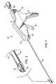
- Fig. 1 is a perspective view of a surgicalapparatus constructed in accordance with a preferredembodiment of the subject invention in a pre-operativecondition;
- Fig. 2 is an enlarged perspective view of thedistal end portion of the surgical apparatus of Fig. 1illustrating the surgical clip releasably supportedthereon;
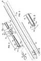
- Fig. 3 is an exploded perspective view of theelongate body of the surgical apparatus of Fig. 1 with thecomponents thereof separated for ease of illustration;
- Fig. 4 is an enlarged perspective view of thedistal end portion of the elongate body of Fig. 3illustrating the surgical clip and clip support structureassociated therewith;
- Fig. 5 is an enlarged perspective view of thedistal end portion of the clip advancement tube of theelongate body illustrated in Fig. 3;
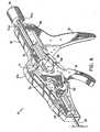
- Fig. 6 is a perspective view of the handleportion of the surgical apparatus of Fig. 1 with the lefthousing section removed to illustrate the internalcomponents housed therein;
- Fig. 7 is an exploded perspective view of thehandle portion shown in Fig. 6 with the components thereofseparated for ease of illustration;
- Fig. 8 is an exploded perspective view of thelocator and the distal end portion of the control rod towhich the locator is mounted;
- Fig. 9 is an enlarged perspective view of thecoupling area of the locator illustrated in Fig. 8;
- Fig. 10 is a perspective view of the locator inan expanded condition mounted to the distal end of thecontrol rod;
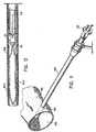
- Fig. 11 is a perspective view of a cannulaextending through a hole in the wall of a blood vessel withthe elongate body of the surgical apparatus of Fig. 1extended therethrough;
- Fig. 12 is an enlarged perspective view of thelocator extended from the distal end portion of thesurgical apparatus of Fig. 1 and collapsed within thecannula;
- Fig. 13 is a side elevational view in cross-sectionof the handle portion of the surgical apparatus ofFig. 1 illustrating the relative orientation of theinternal components associated therewith in a pre-operativecondition;
- Fig. 14 is a side-elevational view in cross-sectionof the handle portion of the surgical apparatus ofFig. 1 illustrating the relative orientation of theinternal components associated therewith in a conditioncorresponding to the locator being disposed in a deployedposition;
- Fig. 15 is a perspective view of a distal endportion of the elongate body of the surgical apparatus ofFig. 1 illustrating the locator disposed in a deployedposition within the interior lumen of a blood vessel;
- Fig. 16 is a side elevational view in cross-sectionof the handle portion of the surgical apparatus of Fig. 1 illustrating the relative orientation of thecomponents associated therewith in positions correspondingto the clip advancement tube being advanced toward a distalposition;
- Fig. 17 is a perspective view of the distal endportion of the elongate body of the surgical apparatus ofFig. 1 illustrating the clip advancement tube advanceddistally to cause the surgical clip to move to an openposition;
- Fig. 18 is a side-elevational view correspondingto Fig. 17 and illustrating the surgical clip in an openposition;
- Fig. 19 is a perspective view of the distal endportion of the elongate body of the surgical apparatus ofFig. 1 illustrating the clip advancement tube advanced to adistal-most position to cause the surgical clip to move toa closed position;
- Fig. 20 is a side elevational view correspondingto Fig. 19 and illustrating the surgical clip in a closedposition;
- Fig. 21 is a side elevational view in cross-sectionof the handle portion of the surgical apparatus ofFig. 1 illustrating the relative orientation of thecomponents associated therewith in positions correspondingto the locator being withdrawn to a retracted position; and
- Fig. 22 is a side elevational view of thesurgical clip applied to the exterior wall of the bloodvessel to close the hole formed therein.
- In the drawings and in the description whichfollows, the term "proximal", as is traditional, will referto the end of the apparatus which is closest to theoperator, while the term "distal" will refer to the end ofthe apparatus which is furthest from the operator.
- Referring now to the drawings wherein likereference numerals identify similar structural elementsdisclosed herein, there is illustrated in Fig. 1 a surgicalapparatus constructed in accordance with a preferredembodiment of the subject application and designatedgenerally by
reference numeral 10.Surgical apparatus 10is adapted and configured to apply a surgical clip to theexterior wall of a blood vessel to at least partially closea hole formed therein during a catheterization procedure,such as, for example, an angioplasty or angiographyprocedure. - Referring to Fig. 1,
surgical apparatus 10includes ahandle assembly 12 consisting of right and lefthousing sections 12a and 12b Which together define anelongated barrel portion 14, astationary handle 16depending frombarrel portion 14, and a pivoting actuationhandle or trigger 18 mounted for movement with respect tostationary handle 16. Anelongate body 20 extends distallyfrom thebarrel portion 14 ofhandle assembly 12, and asurgical clip 22 is releasably supported on a distal endportion ofelongated body 20, as illustrated in Fig. 2. Asbest seen in Fig. 4,surgical clip 22 includes a pair ofopposedclip legs 24a and 24b connected to one another by abail portion 26. Each clip leg is provided with a pair oftissue engagement projections 25 for securely engaging theexterior wall of the blood vessel to which it is applied(see Fig. 22).Clip legs 24a and 24b are normally biasedinto a closed position resulting from the overallconfiguration ofsurgical clip 22 and the material fromwhich the clip is constructed. The material of construction may be selected from bio-compatible materials,including, for example, stainless steel, titanium, andtantalum. Other materials of construction such as bioabsorbablepolymers are also envisioned. - Referring to Fig. 3, the
elongate body 20 ofsurgical apparatus 10 includes amain support shaft 30having anelongate bore 30a extending therethrough.Support shaft 30 extends through thebarrel portion 14 ofhandle assembly 10 and is mounted adjacent a proximal endthereof in a conventional manner. Aclip support fixture 34 is mounted inaxial bore 30a adjacent the distal end ofsupport shaft 30. As best seen in Fig. 4,support fixture 34 is configured to releasably supportsurgical clip 22 andincludes a pair of diametricallyopposed rails 36a and 36bdimensioned to interact with a crescent shapedaperture 38defined in thebail portion 26 ofsurgical clip 22.Rails 36a and 36b terminate in distally extending camming ramps40a and 40b, respectively, which effectuate movement ofclip legs 24a and 24b between closed and open positions assurgical clip 22 is advanced in a distal direction during ahole closing procedure. - Advancement of
surgical clip 22 in a distaldirection relative to camming ramps 40a and 40b isaccomplished through the axial translation of anelongatepusher tube 42.Pusher tube 42 is mounted coaxial withsupport shaft 30 and is configured to translate withrespect thereto in response to manipulation of actuationhandle 18 to drivesurgical clip 22 distally. As best seenin Fig. 5, spaced apart arcuate engagement fingers 44a and44b project distally frompusher tube 42 to engage thecrescent spacedaperture 38 defined in thebail portion 26ofsurgical clip 22. Diametrically opposedelongate slots 46a and 46b are formed in the distal portion ofpusher tube 42 to accommodaterails 36a and 36b during the distal translation of the pusher tube with respect to supportshaft 30. - Referring now to Figs. 6 and 7, a
set pin 45fixedly connects the proximal end ofpusher tube 42 to adistal actuation block 48 which is housed within thebarrelportion 14 ofhandle assembly 12.Actuation block 48includes opposedlateral guide ribs 50a and 50b whichtranslate within opposed guide slots formed in the interiorsurfaces of right and lefthousing sections 12a and 12b,i.e.,guide slot 53. Acoupling link 54 connectsdistalactuation block 48 to actuation handle 18 such thatmanipulation of actuation handle 18causes actuation block 48 to translate distally, urgingpusher tube 42 in a distaldirection. Coupling pins 54a and 54b pivotally connectcoupling link 54 toactuation block 48 and actuation handle18. - Referring now to Figs. 8-10,
surgical apparatus 10 also includes alocator 60 in the form of a collapsibleloop adapted and configured to maintain the distal endportion ofelongate body 20 in a desired position withrespect to the hole in the wall of a blood vessel during ahole closing procedure.Locator 60 includes a pair oflocator arms Locatorarms proximal extension portions arcuate expansion portions 62b and 64b, respectively. As best seen in Fig. 9, theterminal end ofarcuate expansion portion 62b includes anengagement notch 63 for receiving and retaining acomplementary engagement finger 65 formed at the terminalend of arcuate expansion portion 64b. When engaged andsituated in a relaxed unstressed condition,resilientexpansion portions 62b and 64b form an endless loop-like structure. As best seen in Fig. 8, when assembled, theproximal ends ofextension portions coupling flange 66 which isprovided at the distal end of anelongate control rod 68which facilitates movement oflocator 60 with respect tosupporttube 30 during a hole closing procedure. - Referring again to Figs. 6 and 7, the
elongatecontrol rod 68 extends through theaxial bore 30a ofsupport tube 30, into thebarrel portion 14 ofhandleassembly 12, through theaxial bores barrel portion 14, and into theaxial bore 75a of acylindrical control knob 75 operatively associatedwithhandle assembly 12. The proximal end ofcontrol rod 68 is fixedly maintained withinaxial bore 75a ofcontrolknob 75 by a fastener 77 (see Fig. 13).Control knob 75facilitates the longitudinal translation ofcontrol rod 68between proximal and distal positions, and hence themovement oflocator 60 from a collapsed (stressed) positiondisposed within the axial bore 34a ofsupport fixture 34 toa deployed (unstressed) position extending from the distalend ofsupport fixture 34.Control knob 75 includes a pairofengagement tabs housing sections 12a and 12b, i.e.,retentionnotch 76, whenlocator 60 is disposed in a deployedposition. - With continuing reference to Figs. 6 and 7, an
elongate release tube 78 extends proximally from theproximal actuation block 70 to interact with, and effectthe disengagement of,control knob 75 upon manipulation ofactuation handle 18. More particularly,proximal actuationblock 70, which includesguide ribs 72a and 72b thattranslate within opposed guide slots formed inhousingsections 12a and 12b, i.e.,guide slot 73, is connected to actuation handle 18 by acoupling link 82. Coupling pins82a and 82b pivotablyconnect coupling link 82 toactuationblock 70 and actuation handle 18. Thus, manipulation ofactuation handle 18causes actuation block 70 to translatein a proximal direction, whereuponrelease tube 78 enterstheaxial bore 75a ofcontrol knob 75 and urges the controlknob proximally to disengagetabs control knob 75 will not be released untilpusher tube 42 has beenadvanced to its distal-most position. - Referring now to Fig. 11, in use, the
elongatebody 20 ofsurgical apparatus 10 is introduced into theinterior lumen 102 ofblood vessel 104 through aconventional cannula 100 which had previously been extendedthrough thehole 106 formed in the wall ofblood vessel 104during the catheterization procedure. Thereupon,locator 60is moved distally through the translation ofcontrol knob 75 from its proximal-most position illustrated in Fig. 13to its distal-most position illustrated in Fig. 14.Moreover,locator 60 is advanced from its proximal-mostposition disposed within the axial bore 34a ofclip supportfixture 34 to its distal-most position extending from thedistal end ofclip support fixture 34. At such a time, thearcuate expansion portions 62b and 64b oflocator arms cannula 100, asbest seen in Fig. 12. Whencontrol knob 75 is in itsproximal-most position shown in Fig. 14,engagement tabs barrel portion 14, thereby securing the longitudinalorientation ofcontrol rod 68 andlocator 60. - Referring now to Fig. 15, after
locator 60 ismoved into its distal-most position,cannula 100 is withdrawn in a proximal direction with respect to elongatebody 20 to a retracted position. Consequently, thearcuateexpansion portions 62b and 64b oflocator arms elongate body 20 in a desired position withrespect to thehole 106 in the wall ofblood vessel 104.In this deployed position, the geometric plane defined bylocator 60 is oriented parallel to the elongation ofbloodvessel 104. Accordingly, theopposed clip legs 24a and 24bofsurgical clip 22 extend in a direction which isperpendicular to the elongation ofblood vessel 104. - Once
locator 60 is deployed, the clip applicationportion of the vascular hole closure procedure maycommence. To applysurgical clip 22 to the exterior wallofblood vessel 104 to at least partially close thehole 106 formed therein, actuation handle 18 is initially movedthrough the first segment of an actuation stroke, withguide pin 90 serving as the pivot point foractuationhandle 18. During this time, actuation handle 18 causesthedistal actuation block 48 to translate from itsproximal-most position illustrated in Fig. 14 to itsdistal-most position illustrated in Fig. 16 through adistance "xd" within thebarrel portion 14 of handle.assembly 12. As a result,pusher tube 42 is drivendistally, urgingsurgical clip 22 in a distal direction. - Initially, during the distal advancement of
surgical clip 22, theopposed clip legs 24a and 24b ofsurgical clip 22 are moved to an open position as the cliptranslates with respect to camming ramps 40a and 40b, asillustrated in Figs 17 and 18. Subsequently, asactuationblock 48 approaches its distal-most position withinbarrelportion 14,pusher tube 42 advancessurgical clip 22 pastcamming ramps 40a and 40b so thatclip legs 24a and 24breturn to a closed portion, as illustrated in Figs. 19 and 20. More specifically, when camming ramps 40a and 40b meetthe crescent shapedaperture 38 in thebail portion 26 ofsurgical 22,clip legs 24a and 24b return to their normallybiased closed position. - Referring back to Fig. 14, prior to the manipulation ofactuation handle 18 through the first segment of itsactuating stroke, the proximal end of
release tube 78 isdisposed slightly distal of theaxial bore 75a ofcontrolknob 75. As shown in Fig. 16, however, during themanipulation of actuation handle 18 through the first segmentof its actuating stroke, theproximal actuation block 70 andrelease tube 78 translate in a proximal direction through adistance "xp" which is substantially less than the distance"xd" through which thedistal actuation block 48 travelsduring the same period of time. Consequently, during thefirst segment of the actuating stroke ofactuation handle 18,the proximal end ofrelease tube 78 translates only a shortdistance within theaxial bore 75a ofcontrol knob 75,remaining free from contact with the proximal wall ofaxial bore 75a, and having no effect of the longitudinalposition ofcontrol knob 75. - However, as illustrated in Fig. 21, once the
distal actuation block 48 reaches its distal-mostposition, the pivot point of actuation handle 18transfers fromguide pin 90 tocoupling pin 54a. As aresult, the remaining portion of the actuating stroke ofactuation handle 18 is guided by the interaction ofguidepin 90 and thearcuate guide slot 92 formed inactuationhandle 18. Consequently, further manipulation ofactuation handle 18 towardstationary handle 16 urgesproximal actuation block 70 in a proximal direction,drivingrelease tube 78 proximally. As a consequence,control knob 75 is urged proximally, causing the releaseofengagement tabs barrel portion 14,and effectuating the proximal withdrawal ofcontrol rod 68 relative to supporttube 30. Accordingly, thearcuateexpansion portions 62b and 64b oflocator 60 arewithdrawn into the axial bore 34a ofsupport fixture 34,through the crescent shapedaperture 38 formed in thebail portion 26 ofsurgical clip 22. - Following the withdrawal of
locator 60 into theaxial bore 34a ofsupport fixture 34, the distal endportion of theelongated body 20 ofsurgical apparatus 10may be withdrawn from the surgical site. As best seen inFig. 22, at the conclusion of the procedure, theopposedlegs 24a and 24b ofsurgical clip 22 are securely engagedto the exterior wall ofblood vessel 104 such that thehole once formed therein is closed, thereby preventingblood from flowing therethrough.
Claims (12)
- An apparatus (10) for applying a surgical closure to anexterior wall of a blood vessel which defines an interiorlumen of the blood vessel, to at least partially close a holein the wall of the blood vessel, the apparatus comprising:the apparatus beingcharacterized in that:a) a handle portion (12) including an actuation handle(18) mounted for movement through an actuating stroke;b) an elongate body (20) extending distally from thehandle portion and dimensioned to extend through the hole inthe wall of a blood vessel;c) a collapsed locator (60) operatively associated withthe elongate body and mounted for movement from a collapsedretracted position disposed within a distal end portion ofthe elongate body to an expanded deployed position extendingfrom the distal end portion of the elongate body, the locatorbeing adapted and configured to expand within the interiorlumen of the blood vessel in the deployed position tomaintain the distal end portion of the elongate body in adesired location with respect to the hole in the blood vesselwall;d) the surgical closure;e) the surgical closure is a surgical clip (22)releasably supported on the distal end portion of the elongate bodyand configured for application to the exterior wall of theblood vessel to at least partially close the hole formedtherein, the surgical clip having a pair of opposed clip legs(24 a, b) biased into a closed position and connected by a bail portion (26), the bail portion having an apertureprovided therein to accommodate movement of the locatorbetween the deployed position and the retracted position;f) an actuation assembly (48, 70) housed within thehandle portion and operatively connected to the actuationhandle such that movement of the actuation handle through afirst segment of the actuating stroke effectuateslongitudinal movement of the surgical clip toward theexterior wall of the blood vessel and movement of theactuation handle through a second segment of the actuatingstroke effectuates movement of the collapsible locator fromthe deployed position to the retracted position ; andg) the locator forms, in its deployed position, alocator loop.
- An apparatus as recited in claim 1, wherein a controlrod (68) extends from the handle portion through the elongatebody portion and is mounted for movement between a proximalposition and a distal position to effectuate the movement ofthe collapsed locator loop from the retracted position to thedeployed position.
- An apparatus as recited in claim 2, wherein a controlknob (75) is operatively mounted to a proximal end of thecontrol rod to facilitate the longitudinal movement thereofand includes means (74 a, b) for releasably engaging thehandle portion when the collapsible locator loop is disposedin the deployed position.
- An apparatus as recited in claim 3, wherein the elongatebody portion includes an outer tubular member (42) mountedfor axial movement with respect to the handle portion betweena proximal position and a distal position for effectuatingsaid longitudinal movement of the surgical clip.
- An apparatus as recited in claim 4, wherein a pair ofdiametrically opposed camming ramps (40 a, b) are formed on asupport shaft (30) at a distal end of the elongate body,distal of the clip support position, the camming rampscausing the opposed legs of the surgical clip to move between-aclosed position and an open position in response tolongitudinal movement of the outer tubular member from thedistal position toward the proximal position.
- An apparatus as recited in claim 5, wherein movement ofthe actuation handle through the first segment of theactuating stroke causes the outer tubular member to move fromthe proximal position to the distal position, and movement ofthe actuation handle through the second segment of theactuating stroke causes the control rod to move from thedistal position to the proximal position.
- An apparatus as recited in claim 6, wherein movement ofthe actuation handle through the second segment of theactuating stroke releases the control knob from itsengagement with the handle portion.
- An apparatus as recited in claim 7, wherein the actuating assembly includes a distalactuating member (48) connected to a proximal end of theouter tubular member and a proximal actuating member (70)connected to a release tube (78) which is dimensioned tointeract with the actuator upon movement of the actuationhandle through the second segment of the actuating stroke.
- An apparatus as recited in any one of the precedingclaims, wherein at least a portion of the locator loop isformed from a material having shape memory characteristics.
- An apparatus as claimed in claim 3, wherein the meansfor releasably engaging the handle portion includes a pair ofopposed locking tabs(74 a, b) configured to releasably engagecomplementary reception structures provided on a proximal end portion of the handle portion when the collapsible locator isdisposed in the deployed position.
- An apparatus as claimed in any one of the precedingclaims, wherein support structure (34) is provided adjacent adistal end of the elongate body for releasably supporting thesurgical clip.
- An apparatus as claimed in claim 8, wherein a firstcontrol link (54) connects the distal actuating member to theactuation handle and second control link (82) connects theproximal actuating member to the actuation handle.
Applications Claiming Priority (2)
| Application Number | Priority Date | Filing Date | Title |
|---|---|---|---|
| US08/545,974US5674231A (en) | 1995-10-20 | 1995-10-20 | Apparatus and method for vascular hole closure |
| US545974 | 1995-10-20 |
Publications (3)
| Publication Number | Publication Date |
|---|---|
| EP0774237A2 EP0774237A2 (en) | 1997-05-21 |
| EP0774237A3 EP0774237A3 (en) | 1997-07-30 |
| EP0774237B1true EP0774237B1 (en) | 2003-04-02 |
Family
ID=24178314
Family Applications (1)
| Application Number | Title | Priority Date | Filing Date |
|---|---|---|---|
| EP96116909AExpired - LifetimeEP0774237B1 (en) | 1995-10-20 | 1996-10-21 | Apparatus for vascular hole closure |
Country Status (5)
| Country | Link |
|---|---|
| US (1) | US5674231A (en) |
| EP (1) | EP0774237B1 (en) |
| CA (1) | CA2188210C (en) |
| DE (1) | DE69627107T2 (en) |
| ES (1) | ES2192592T3 (en) |
Cited By (55)
| Publication number | Priority date | Publication date | Assignee | Title |
|---|---|---|---|---|
| US6979338B1 (en) | 1998-05-29 | 2005-12-27 | By-Pass Inc. | Low profile anastomosis connector |
| USD611144S1 (en) | 2006-06-28 | 2010-03-02 | Abbott Laboratories | Apparatus for delivering a closure element |
| US7806904B2 (en) | 2000-12-07 | 2010-10-05 | Integrated Vascular Systems, Inc. | Closure device |
| US7806910B2 (en) | 2002-11-26 | 2010-10-05 | Abbott Laboratories | Multi-element biased suture clip |
| US7819895B2 (en) | 2000-01-05 | 2010-10-26 | Integrated Vascular Systems, Inc. | Vascular sheath with bioabsorbable puncture site closure apparatus and methods of use |
| US7828817B2 (en) | 2000-01-05 | 2010-11-09 | Integrated Vascular Systems, Inc. | Apparatus and methods for delivering a closure device |
| US7841502B2 (en) | 2007-12-18 | 2010-11-30 | Abbott Laboratories | Modular clip applier |
| US7850797B2 (en) | 2002-12-31 | 2010-12-14 | Integrated Vascular Systems, Inc. | Methods for manufacturing a clip and clip |
| US7850709B2 (en) | 2002-06-04 | 2010-12-14 | Abbott Vascular Inc. | Blood vessel closure clip and delivery device |
| US7867249B2 (en) | 2003-01-30 | 2011-01-11 | Integrated Vascular Systems, Inc. | Clip applier and methods of use |
| US7879071B2 (en) | 2000-12-07 | 2011-02-01 | Integrated Vascular Systems, Inc. | Closure device and methods for making and using them |
| US7887563B2 (en) | 2001-06-07 | 2011-02-15 | Abbott Vascular Inc. | Surgical staple |
| US7931669B2 (en) | 2000-01-05 | 2011-04-26 | Integrated Vascular Systems, Inc. | Integrated vascular device with puncture site closure component and sealant and methods of use |
| US8007512B2 (en) | 2002-02-21 | 2011-08-30 | Integrated Vascular Systems, Inc. | Plunger apparatus and methods for delivering a closure device |
| US8202293B2 (en) | 2003-01-30 | 2012-06-19 | Integrated Vascular Systems, Inc. | Clip applier and methods of use |
| US8202294B2 (en) | 2003-01-30 | 2012-06-19 | Integrated Vascular Systems, Inc. | Clip applier and methods of use |
| US8226681B2 (en) | 2007-06-25 | 2012-07-24 | Abbott Laboratories | Methods, devices, and apparatus for managing access through tissue |
| US8303624B2 (en) | 2010-03-15 | 2012-11-06 | Abbott Cardiovascular Systems, Inc. | Bioabsorbable plug |
| US8313497B2 (en) | 2005-07-01 | 2012-11-20 | Abbott Laboratories | Clip applier and methods of use |
| US8323312B2 (en) | 2008-12-22 | 2012-12-04 | Abbott Laboratories | Closure device |
| US8398676B2 (en) | 2008-10-30 | 2013-03-19 | Abbott Vascular Inc. | Closure device |
| US8398656B2 (en) | 2003-01-30 | 2013-03-19 | Integrated Vascular Systems, Inc. | Clip applier and methods of use |
| US8556932B2 (en) | 2011-05-19 | 2013-10-15 | Abbott Cardiovascular Systems, Inc. | Collapsible plug for tissue closure |
| US8556930B2 (en) | 2006-06-28 | 2013-10-15 | Abbott Laboratories | Vessel closure device |
| US8590760B2 (en) | 2004-05-25 | 2013-11-26 | Abbott Vascular Inc. | Surgical stapler |
| US8597325B2 (en) | 2000-12-07 | 2013-12-03 | Integrated Vascular Systems, Inc. | Apparatus and methods for providing tactile feedback while delivering a closure device |
| US8603116B2 (en) | 2010-08-04 | 2013-12-10 | Abbott Cardiovascular Systems, Inc. | Closure device with long tines |
| US8617184B2 (en) | 2011-02-15 | 2013-12-31 | Abbott Cardiovascular Systems, Inc. | Vessel closure system |
| US8672953B2 (en) | 2007-12-17 | 2014-03-18 | Abbott Laboratories | Tissue closure system and methods of use |
| US8690910B2 (en) | 2000-12-07 | 2014-04-08 | Integrated Vascular Systems, Inc. | Closure device and methods for making and using them |
| US8758400B2 (en) | 2000-01-05 | 2014-06-24 | Integrated Vascular Systems, Inc. | Closure system and methods of use |
| US8758399B2 (en) | 2010-08-02 | 2014-06-24 | Abbott Cardiovascular Systems, Inc. | Expandable bioabsorbable plug apparatus and method |
| US8758398B2 (en) | 2006-09-08 | 2014-06-24 | Integrated Vascular Systems, Inc. | Apparatus and method for delivering a closure element |
| US8784447B2 (en) | 2000-09-08 | 2014-07-22 | Abbott Vascular Inc. | Surgical stapler |
| US8808310B2 (en) | 2006-04-20 | 2014-08-19 | Integrated Vascular Systems, Inc. | Resettable clip applier and reset tools |
| US8821534B2 (en) | 2010-12-06 | 2014-09-02 | Integrated Vascular Systems, Inc. | Clip applier having improved hemostasis and methods of use |
| US8858594B2 (en) | 2008-12-22 | 2014-10-14 | Abbott Laboratories | Curved closure device |
| US8893947B2 (en) | 2007-12-17 | 2014-11-25 | Abbott Laboratories | Clip applier and methods of use |
| US8905937B2 (en) | 2009-02-26 | 2014-12-09 | Integrated Vascular Systems, Inc. | Methods and apparatus for locating a surface of a body lumen |
| US8920442B2 (en) | 2005-08-24 | 2014-12-30 | Abbott Vascular Inc. | Vascular opening edge eversion methods and apparatuses |
| US8926633B2 (en) | 2005-06-24 | 2015-01-06 | Abbott Laboratories | Apparatus and method for delivering a closure element |
| US9089311B2 (en) | 2009-01-09 | 2015-07-28 | Abbott Vascular Inc. | Vessel closure devices and methods |
| US9089674B2 (en) | 2000-10-06 | 2015-07-28 | Integrated Vascular Systems, Inc. | Apparatus and methods for positioning a vascular sheath |
| US9149276B2 (en) | 2011-03-21 | 2015-10-06 | Abbott Cardiovascular Systems, Inc. | Clip and deployment apparatus for tissue closure |
| US9173644B2 (en) | 2009-01-09 | 2015-11-03 | Abbott Vascular Inc. | Closure devices, systems, and methods |
| US9282965B2 (en) | 2008-05-16 | 2016-03-15 | Abbott Laboratories | Apparatus and methods for engaging tissue |
| US9314230B2 (en) | 2009-01-09 | 2016-04-19 | Abbott Vascular Inc. | Closure device with rapidly eroding anchor |
| US9332976B2 (en) | 2011-11-30 | 2016-05-10 | Abbott Cardiovascular Systems, Inc. | Tissue closure device |
| US9364209B2 (en) | 2012-12-21 | 2016-06-14 | Abbott Cardiovascular Systems, Inc. | Articulating suturing device |
| US9414820B2 (en) | 2009-01-09 | 2016-08-16 | Abbott Vascular Inc. | Closure devices, systems, and methods |
| US9414824B2 (en) | 2009-01-16 | 2016-08-16 | Abbott Vascular Inc. | Closure devices, systems, and methods |
| US9456811B2 (en) | 2005-08-24 | 2016-10-04 | Abbott Vascular Inc. | Vascular closure methods and apparatuses |
| US9486191B2 (en) | 2009-01-09 | 2016-11-08 | Abbott Vascular, Inc. | Closure devices |
| US9585647B2 (en) | 2009-08-26 | 2017-03-07 | Abbott Laboratories | Medical device for repairing a fistula |
| US12383246B2 (en) | 2020-10-12 | 2025-08-12 | Abbott Cardiovascular Systems, Inc. | Vessel closure device with improved safety and tract hemostasis |
Families Citing this family (124)
| Publication number | Priority date | Publication date | Assignee | Title |
|---|---|---|---|---|
| US6524326B1 (en) | 1995-12-07 | 2003-02-25 | Loma Linda University Medical Center | Tissue opening locator and everter and method |
| US6004341A (en)* | 1996-12-05 | 1999-12-21 | Loma Linda University Medical Center | Vascular wound closure device |
| US6425901B1 (en) | 1995-12-07 | 2002-07-30 | Loma Linda University Medical Center | Vascular wound closure system |
| US6287322B1 (en) | 1995-12-07 | 2001-09-11 | Loma Linda University Medical Center | Tissue opening locator and everter and method |
| GB2318295A (en) | 1996-10-17 | 1998-04-22 | Malachy Gleeson | Wire-guided surgical stapler for closure of a puncture site in a blood vessel |
| US6036702A (en) | 1997-04-23 | 2000-03-14 | Vascular Science Inc. | Medical grafting connectors and fasteners |
| US5861005A (en)* | 1997-02-11 | 1999-01-19 | X-Site, L.L.C. | Arterial stapling device |
| EP1085837A4 (en)* | 1998-05-29 | 2004-06-02 | By Pass Inc | Vascular port device |
| US8137364B2 (en) | 2003-09-11 | 2012-03-20 | Abbott Laboratories | Articulating suturing device and method |
| US6964668B2 (en) | 1999-03-04 | 2005-11-15 | Abbott Laboratories | Articulating suturing device and method |
| US7662161B2 (en) | 1999-09-13 | 2010-02-16 | Rex Medical, L.P | Vascular hole closure device |
| US7341595B2 (en) | 1999-09-13 | 2008-03-11 | Rex Medical, L.P | Vascular hole closure device |
| US8083766B2 (en) | 1999-09-13 | 2011-12-27 | Rex Medical, Lp | Septal defect closure device |
| AU7373700A (en) | 1999-09-13 | 2001-04-17 | Rex Medical, Lp | Vascular closure |
| US7942888B2 (en) | 1999-09-13 | 2011-05-17 | Rex Medical, L.P. | Vascular hole closure device |
| US7267679B2 (en) | 1999-09-13 | 2007-09-11 | Rex Medical, L.P | Vascular hole closure device |
| US6911032B2 (en) | 1999-11-18 | 2005-06-28 | Scimed Life Systems, Inc. | Apparatus and method for compressing body tissue |
| US6428548B1 (en) | 1999-11-18 | 2002-08-06 | Russell F. Durgin | Apparatus and method for compressing body tissue |
| ATE302568T1 (en)* | 2000-01-05 | 2005-09-15 | Integrated Vascular Sys Inc | DEVICE FOR CLOSING A PUNCTURE WOUND |
| US6780197B2 (en) | 2000-01-05 | 2004-08-24 | Integrated Vascular Systems, Inc. | Apparatus and methods for delivering a vascular closure device to a body lumen |
| US6197042B1 (en) | 2000-01-05 | 2001-03-06 | Medical Technology Group, Inc. | Vascular sheath with puncture site closure apparatus and methods of use |
| US9579091B2 (en)* | 2000-01-05 | 2017-02-28 | Integrated Vascular Systems, Inc. | Closure system and methods of use |
| US6547806B1 (en) | 2000-02-04 | 2003-04-15 | Ni Ding | Vascular sealing device and method of use |
| US6547798B1 (en)* | 2000-05-04 | 2003-04-15 | Inbae Yoon | Ring applicator and method for applying elastic rings to anatomical tissue structures |
| US6890342B2 (en) | 2000-08-02 | 2005-05-10 | Loma Linda University | Method and apparatus for closing vascular puncture using hemostatic material |
| SE0002878D0 (en)* | 2000-08-11 | 2000-08-11 | Kimblad Ola | Device and method of treatment of atrioventricular regurgitation |
| US8551134B2 (en)* | 2000-09-01 | 2013-10-08 | Medtronic Vascular, Inc. | Wound site management and wound closure device |
| US6322580B1 (en)* | 2000-09-01 | 2001-11-27 | Angiolink Corporation | Wound site management and wound closure device |
| ZA200006432B (en) | 2000-09-08 | 2000-12-08 | Christy Cummins | Surgical micro-stapling instrument. |
| US6719777B2 (en) | 2000-12-07 | 2004-04-13 | Integrated Vascular Systems, Inc. | Closure device and methods for making and using them |
| IES20010748A2 (en)* | 2001-08-09 | 2003-02-19 | Christy Cummins | Surgical Stapling Device and Method |
| IES20010749A2 (en)* | 2001-08-09 | 2003-02-19 | Christy Cummins | Surgical Stapling Device |
| ATE342000T1 (en) | 2002-06-14 | 2006-11-15 | Univ Loma Linda Med | DEVICE FOR CLOSING VASCULAR WOUNDS |
| US8083804B2 (en)* | 2002-06-19 | 2011-12-27 | Tyco Healthcare Group Lp | Method and apparatus for anastomosis including annular joining member |
| EP1646320B1 (en)* | 2002-07-03 | 2009-02-25 | Abbott Vascular Inc | Surgical stapling device |
| US7322995B2 (en)* | 2002-09-13 | 2008-01-29 | Damage Control Surgical Technologies, Inc. | Method and apparatus for vascular and visceral clipping |
| JP2006509595A (en)* | 2002-12-16 | 2006-03-23 | エドリッチ・ヴァスキュラー・ディヴァイシズ,インコーポレイテッド | Multiple stapling instruments for narrow vessels |
| DE10259411A1 (en)* | 2002-12-19 | 2004-07-08 | Forschungszentrum Karlsruhe Gmbh | Medical clip and device for applying such a device |
| US20040225301A1 (en)* | 2003-05-05 | 2004-11-11 | St. Jude Medical, Daig Division, Inc. | Loop closure apparatus and method |
| DE602004031953D1 (en) | 2003-08-14 | 2011-05-05 | Univ Loma Linda Med | |
| US7462188B2 (en) | 2003-09-26 | 2008-12-09 | Abbott Laboratories | Device and method for suturing intracardiac defects |
| US7326230B2 (en)* | 2003-10-23 | 2008-02-05 | Sundaram Ravikumar | Vascular sealing device and method of use |
| US8128652B2 (en) | 2003-11-13 | 2012-03-06 | St. Jude Medical Puerto Rico Llc | Method and apparatus for sealing an internal tissue puncture incorporating a block and tackle |
| US7998104B2 (en) | 2003-11-21 | 2011-08-16 | Silk Road Medical, Inc. | Method and apparatus for treating a carotid artery |
| US7597705B2 (en) | 2003-12-03 | 2009-10-06 | St. Jude Medical Puerto Rico Llc | Vascular puncture seal anchor nest |
| US7621937B2 (en) | 2003-12-03 | 2009-11-24 | St. Jude Medical Puerto Rico LC | Vascular sealing device with high surface area sealing plug |
| US8882786B2 (en)* | 2004-02-17 | 2014-11-11 | Lawrence Livermore National Security, Llc. | System for closure of a physical anomaly |
| GB0420505D0 (en) | 2004-09-14 | 2004-10-20 | Wild Andrew M | Apparatus for dispensing surgical clips |
| US7182763B2 (en)* | 2004-11-23 | 2007-02-27 | Instrasurgical, Llc | Wound closure device |
| US7458978B1 (en) | 2005-03-28 | 2008-12-02 | Cardica, Inc. | Vascular closure system utilizing a staple |
| US7344544B2 (en)* | 2005-03-28 | 2008-03-18 | Cardica, Inc. | Vascular closure system |
| US7618436B2 (en) | 2005-04-12 | 2009-11-17 | St. Jude Medical Puerto Rico Llc | Tissue puncture closure device with scroll gear transmission tamping system |
| WO2006115689A1 (en) | 2005-04-22 | 2006-11-02 | Rex Medical, L.P. | Closure device for left atrial appendage |
| US8083754B2 (en) | 2005-08-08 | 2011-12-27 | Abbott Laboratories | Vascular suturing device with needle capture |
| US8758397B2 (en)* | 2005-08-24 | 2014-06-24 | Abbott Vascular Inc. | Vascular closure methods and apparatuses |
| US20070060895A1 (en) | 2005-08-24 | 2007-03-15 | Sibbitt Wilmer L Jr | Vascular closure methods and apparatuses |
| US8382794B2 (en) | 2006-01-04 | 2013-02-26 | St. Jude Medical Puerto Rico Llc | Balloon insertion apparatus and method of sealing a tissue puncture |
| US7875053B2 (en)* | 2006-09-15 | 2011-01-25 | Cardica, Inc. | Apparatus and method for closure of patent foramen ovale |
| US7749248B2 (en)* | 2006-09-18 | 2010-07-06 | St. Jude Medical Puerto Rico Llc | Flexible tamping device |
| WO2008066920A2 (en)* | 2006-11-28 | 2008-06-05 | Stryker Development Llc | Gastrotomy closure device |
| US8920305B2 (en) | 2007-01-19 | 2014-12-30 | Advanced Bariatric Technology, Llc | Vertically oriented band for stomach |
| US20080173691A1 (en)* | 2007-01-24 | 2008-07-24 | Medtronic Vascular, Inc. | Low-Profile Vascular Closure Systems and Methods of Using Same |
| US8128657B2 (en)* | 2007-02-27 | 2012-03-06 | Olympus Medical Systems Corp. | Suture instrument |
| US8308766B2 (en)* | 2007-02-27 | 2012-11-13 | Olympus Medical Systems Corp. | Endoscopic treatment instrument |
| US7473258B2 (en)* | 2007-03-08 | 2009-01-06 | Cardica, Inc. | Surgical stapler |
| US7533790B1 (en) | 2007-03-08 | 2009-05-19 | Cardica, Inc. | Surgical stapler |
| US8147504B2 (en)* | 2007-05-05 | 2012-04-03 | Medtronic, Inc. | Apparatus and methods for delivering fasteners during valve replacement |
| US8574244B2 (en) | 2007-06-25 | 2013-11-05 | Abbott Laboratories | System for closing a puncture in a vessel wall |
| EP2166954A1 (en) | 2007-07-13 | 2010-03-31 | Rex Medical, L.P. | Vascular hole closure device |
| US8858490B2 (en) | 2007-07-18 | 2014-10-14 | Silk Road Medical, Inc. | Systems and methods for treating a carotid artery |
| EP2497520B1 (en) | 2007-07-18 | 2022-04-13 | Silk Road Medical, Inc. | Systems for establishing retrograde carotid arterial blood flow |
| US8568445B2 (en) | 2007-08-21 | 2013-10-29 | St. Jude Medical Puerto Rico Llc | Extra-vascular sealing device and method |
| US8333787B2 (en) | 2007-12-31 | 2012-12-18 | St. Jude Medical Puerto Rico Llc | Vascular closure device having a flowable sealing material |
| US20090093826A1 (en)* | 2007-10-05 | 2009-04-09 | Cardica, Inc. | Patent Foramen Ovale Closure System |
| US8556931B2 (en)* | 2007-12-17 | 2013-10-15 | Abbott Laboratories | Methods for imaging a delivery system |
| US9282953B2 (en) | 2007-12-31 | 2016-03-15 | St. Jude Medical Puerto Rico Llc | Systems and methods for locating and closing a tissue puncture |
| US8840640B2 (en) | 2007-12-31 | 2014-09-23 | St. Jude Medical Puerto Rico Llc | Vascular closure device having an improved plug |
| JP2011510796A (en) | 2008-02-05 | 2011-04-07 | シルク・ロード・メディカル・インコーポレイテッド | Intervention catheter system and method |
| US9226738B2 (en) | 2008-02-15 | 2016-01-05 | Rex Medical, L.P. | Vascular hole closure delivery device |
| US20110029013A1 (en) | 2008-02-15 | 2011-02-03 | Mcguckin James F | Vascular Hole Closure Device |
| US8920462B2 (en) | 2008-02-15 | 2014-12-30 | Rex Medical, L.P. | Vascular hole closure device |
| US8070772B2 (en) | 2008-02-15 | 2011-12-06 | Rex Medical, L.P. | Vascular hole closure device |
| US8920463B2 (en) | 2008-02-15 | 2014-12-30 | Rex Medical, L.P. | Vascular hole closure device |
| US8491629B2 (en) | 2008-02-15 | 2013-07-23 | Rex Medical | Vascular hole closure delivery device |
| US20090254121A1 (en)* | 2008-04-02 | 2009-10-08 | Cardica, Inc. | Vascular Closure with Multi-Pronged Clip |
| EP2323566A2 (en) | 2008-08-13 | 2011-05-25 | Silk Road Medical, Inc. | Suture delivery device |
| US8574245B2 (en) | 2008-08-13 | 2013-11-05 | Silk Road Medical, Inc. | Suture delivery device |
| WO2010022060A1 (en) | 2008-08-19 | 2010-02-25 | Wilson-Cook Medical Inc. | Apparatus for removing lymph nodes or anchoring into tissue during a translumenal procedure |
| EP2330981B1 (en) | 2008-08-26 | 2013-11-27 | St. Jude Medical, Inc. | System for sealing percutaneous punctures |
| EP2328482B1 (en) | 2008-08-29 | 2012-09-26 | Cook Medical Technologies LLC | Stapling device for closing perforations |
| US8192461B2 (en) | 2008-09-11 | 2012-06-05 | Cook Medical Technologies Llc | Methods for facilitating closure of a bodily opening using one or more tacking devices |
| US8377095B2 (en) | 2008-12-05 | 2013-02-19 | Cook Medical Technologies, LLC | Tissue anchors for purse-string closure of perforations |
| AU2009324819B2 (en) | 2008-12-09 | 2014-04-17 | Cook Medical Technologies Llc | Retractable tacking device |
| US8239004B2 (en)* | 2008-12-17 | 2012-08-07 | Abbott Laboratories | Methods for imaging an implant site |
| EP2389122B1 (en) | 2008-12-19 | 2015-03-04 | Cook Medical Technologies LLC | Clip devices |
| CA2757554A1 (en) | 2009-04-03 | 2010-10-07 | Cook Medical Technologies Llc | Tissue anchors and medical devices for rapid deployment of tissue anchors |
| EP2413809B1 (en) | 2009-04-03 | 2014-10-08 | Cook Medical Technologies LLC | Medical devices for rapid deployment and fixation of tissue anchors |
| JP2012527970A (en) | 2009-05-28 | 2012-11-12 | クック メディカル テクノロジーズ エルエルシー | Hail-fastening device and hail-fastening device deployment method |
| WO2010151382A1 (en) | 2009-06-26 | 2010-12-29 | Wilson-Cook Medical Inc. | Linear clamps for anastomosis |
| US20110034802A1 (en)* | 2009-08-05 | 2011-02-10 | Abbott Laboratories | Systems, methods, and apparatus for imaging an implantable device and methods for manufacturing |
| US8545525B2 (en) | 2009-11-03 | 2013-10-01 | Cook Medical Technologies Llc | Planar clamps for anastomosis |
| WO2011094700A1 (en)* | 2010-01-29 | 2011-08-04 | Advanced Bariatric Technology, Llc | Surgical clamp and surgical clamp installation tool |
| US8603121B2 (en) | 2010-04-14 | 2013-12-10 | Cook Medical Technologies Llc | Systems and methods for creating anastomoses |
| US9138212B1 (en)* | 2010-07-19 | 2015-09-22 | Cardica, Inc. | Anchor system for PFO closure |
| US9370353B2 (en) | 2010-09-01 | 2016-06-21 | Abbott Cardiovascular Systems, Inc. | Suturing devices and methods |
| US9414822B2 (en) | 2011-05-19 | 2016-08-16 | Abbott Cardiovascular Systems, Inc. | Tissue eversion apparatus and tissue closure device and methods for use thereof |
| EP2717781B1 (en) | 2011-06-07 | 2019-02-06 | St. Jude Medical Puerto Rico LLC | Large bore closure device |
| EP2747667B1 (en) | 2011-11-16 | 2016-03-09 | St. Jude Medical Puerto Rico LLC | Vascular closure system |
| WO2013074490A1 (en) | 2011-11-16 | 2013-05-23 | St. Jude Medical Puerto Rico Llc | Large bore vascular closure device with inner and outer seals |
| WO2013081905A1 (en) | 2011-11-28 | 2013-06-06 | St. Jude Medical Puerto Rico Llc | Anchor device for large bore vascular closure |
| US9358077B2 (en) | 2012-03-14 | 2016-06-07 | St. Jude Medical Puerto Rico Llc | Markers for tissue tract depth indication and methods |
| US8858573B2 (en) | 2012-04-10 | 2014-10-14 | Abbott Cardiovascular Systems, Inc. | Apparatus and method for suturing body lumens |
| US9241707B2 (en) | 2012-05-31 | 2016-01-26 | Abbott Cardiovascular Systems, Inc. | Systems, methods, and devices for closing holes in body lumens |
| WO2014021937A1 (en) | 2012-08-03 | 2014-02-06 | St. Jude Medical Puerto Rico Llc | Large bore introducer with improved seal |
| EP2882354B1 (en) | 2012-08-09 | 2020-09-23 | Advanced Bariatric Technology, LLC | Polymer overmolded bariatric clamp |
| US10159479B2 (en) | 2012-08-09 | 2018-12-25 | Silk Road Medical, Inc. | Suture delivery device |
| WO2014031147A1 (en) | 2012-08-24 | 2014-02-27 | St. Jude Medical Puerto Rico Llc | Balloon bailout and bioadhesive delivery device for suture based closure and methods |
| US10136885B2 (en) | 2013-03-11 | 2018-11-27 | St. Jude Medical Puerto Rico Llc | Three suture large bore closure device and methods |
| US9055933B2 (en) | 2013-03-12 | 2015-06-16 | St. Jude Medical Puerto Rico Llc | Large bore closure secondary hemostasis bioadhesive delivery systems and methods |
| WO2015175537A1 (en) | 2014-05-16 | 2015-11-19 | Silk Road Medical, Inc. | Vessel access and closure assist system and method |
| MY206744A (en) | 2014-08-26 | 2025-01-03 | Advanced Bariatric Tech Llc | Bariatric clamp with suture portions, magnetic inserts, and curvature |
| WO2018009669A1 (en) | 2016-07-07 | 2018-01-11 | Advanced Bariatric Technology, Llc | Inflatable bariatric clamp |
| DE102018104549A1 (en) | 2018-02-28 | 2019-08-29 | Venock Medical Gmbh | Device and method for closing a tissue opening |
| US11504105B2 (en) | 2019-01-25 | 2022-11-22 | Rex Medical L.P. | Vascular hole closure device |
Citations (1)
| Publication number | Priority date | Publication date | Assignee | Title |
|---|---|---|---|---|
| US5342393A (en)* | 1992-08-27 | 1994-08-30 | Duke University | Method and device for vascular repair |
Family Cites Families (45)
| Publication number | Priority date | Publication date | Assignee | Title |
|---|---|---|---|---|
| US2513771A (en)* | 1948-12-09 | 1950-07-04 | Carl T Williams | Incision closer |
| US4532134A (en)* | 1981-04-06 | 1985-07-30 | Malette William Graham | Method of achieving hemostasis, inhibiting fibroplasia, and promoting tissue regeneration in a tissue wound |
| US4854320A (en)* | 1983-10-06 | 1989-08-08 | Laser Surgery Software, Inc. | Laser healing method and apparatus |
| US4929240A (en)* | 1983-12-01 | 1990-05-29 | University Of New Mexico | Surgical clip and applier |
| USRE34866E (en)* | 1987-02-17 | 1995-02-21 | Kensey Nash Corporation | Device for sealing percutaneous puncture in a vessel |
| US4744364A (en)* | 1987-02-17 | 1988-05-17 | Intravascular Surgical Instruments, Inc. | Device for sealing percutaneous puncture in a vessel |
| US4852568A (en)* | 1987-02-17 | 1989-08-01 | Kensey Nash Corporation | Method and apparatus for sealing an opening in tissue of a living being |
| US4890612A (en) | 1987-02-17 | 1990-01-02 | Kensey Nash Corporation | Device for sealing percutaneous puncture in a vessel |
| US5030226A (en)* | 1988-01-15 | 1991-07-09 | United States Surgical Corporation | Surgical clip applicator |
| US5100420A (en)* | 1989-07-18 | 1992-03-31 | United States Surgical Corporation | Apparatus and method for applying surgical clips in laparoscopic or endoscopic procedures |
| US5330445A (en)* | 1988-05-26 | 1994-07-19 | Haaga John R | Sheath for wound closure caused by a medical tubular device |
| US5254105A (en)* | 1988-05-26 | 1993-10-19 | Haaga John R | Sheath for wound closure caused by a medical tubular device |
| US5053046A (en)* | 1988-08-22 | 1991-10-01 | Woodrow W. Janese | Dural sealing needle and method of use |
| FR2641692A1 (en)* | 1989-01-17 | 1990-07-20 | Nippon Zeon Co | Plug for closing an opening for a medical application, and device for the closure plug making use thereof |
| US5061274A (en)* | 1989-12-04 | 1991-10-29 | Kensey Nash Corporation | Plug device for sealing openings and method of use |
| JP2528602B2 (en)* | 1989-12-04 | 1996-08-28 | ケンゼー・ナッシュ・コーポレーション | Plug device for sealing the opening |
| US5226908A (en)* | 1989-12-05 | 1993-07-13 | Inbae Yoon | Multi-functional instruments and stretchable ligating and occluding devices |
| US5217473A (en)* | 1989-12-05 | 1993-06-08 | Inbae Yoon | Multi-functional instruments and stretchable ligating and occluding devices |
| US5021059A (en)* | 1990-05-07 | 1991-06-04 | Kensey Nash Corporation | Plug device with pulley for sealing punctures in tissue and methods of use |
| US5071417A (en)* | 1990-06-15 | 1991-12-10 | Rare Earth Medical Lasers, Inc. | Laser fusion of biological materials |
| DE4024106C1 (en)* | 1990-07-30 | 1992-04-23 | Ethicon Gmbh & Co Kg, 2000 Norderstedt, De | |
| US5391183A (en)* | 1990-09-21 | 1995-02-21 | Datascope Investment Corp | Device and method sealing puncture wounds |
| US5108421A (en)* | 1990-10-01 | 1992-04-28 | Quinton Instrument Company | Insertion assembly and method of inserting a vessel plug into the body of a patient |
| US5192300A (en)* | 1990-10-01 | 1993-03-09 | Quinton Instrument Company | Insertion assembly and method of inserting a vessel plug into the body of a patient |
| US5221259A (en)* | 1990-12-27 | 1993-06-22 | Novoste Corporation | Wound treating device and method of using same |
| US5129882A (en)* | 1990-12-27 | 1992-07-14 | Novoste Corporation | Wound clotting device and method of using same |
| US5156613A (en)* | 1991-02-13 | 1992-10-20 | Interface Biomedical Laboratories Corp. | Collagen welding rod material for use in tissue welding |
| US5310407A (en)* | 1991-06-17 | 1994-05-10 | Datascope Investment Corp. | Laparoscopic hemostat delivery system and method for using said system |
| NL9101051A (en)* | 1991-06-18 | 1993-01-18 | Ashridge Ag | CLOSING DEVICE FOR A VESSEL OR THE LIKE. |
| US5290310A (en)* | 1991-10-30 | 1994-03-01 | Howmedica, Inc. | Hemostatic implant introducer |
| US5282827A (en)* | 1991-11-08 | 1994-02-01 | Kensey Nash Corporation | Hemostatic puncture closure system and method of use |
| US5411520A (en)* | 1991-11-08 | 1995-05-02 | Kensey Nash Corporation | Hemostatic vessel puncture closure system utilizing a plug located within the puncture tract spaced from the vessel, and method of use |
| US5222974A (en)* | 1991-11-08 | 1993-06-29 | Kensey Nash Corporation | Hemostatic puncture closure system and method of use |
| US5242456A (en)* | 1991-11-21 | 1993-09-07 | Kensey Nash Corporation | Apparatus and methods for clamping tissue and reflecting the same |
| US5413571A (en)* | 1992-07-16 | 1995-05-09 | Sherwood Medical Company | Device for sealing hemostatic incisions |
| US5292332A (en)* | 1992-07-27 | 1994-03-08 | Lee Benjamin I | Methods and device for percutanceous sealing of arterial puncture sites |
| US5443481A (en)* | 1992-07-27 | 1995-08-22 | Lee; Benjamin I. | Methods and device for percutaneous sealing of arterial puncture sites |
| US5415657A (en)* | 1992-10-13 | 1995-05-16 | Taymor-Luria; Howard | Percutaneous vascular sealing method |
| US5304184A (en)* | 1992-10-19 | 1994-04-19 | Indiana University Foundation | Apparatus and method for positive closure of an internal tissue membrane opening |
| US5383897A (en)* | 1992-10-19 | 1995-01-24 | Shadyside Hospital | Method and apparatus for closing blood vessel punctures |
| US5417699A (en)* | 1992-12-10 | 1995-05-23 | Perclose Incorporated | Device and method for the percutaneous suturing of a vascular puncture site |
| US5383896A (en)* | 1993-05-25 | 1995-01-24 | Gershony; Gary | Vascular sealing device |
| US5383899A (en)* | 1993-09-28 | 1995-01-24 | Hammerslag; Julius G. | Method of using a surface opening adhesive sealer |
| US5370660A (en)* | 1993-11-01 | 1994-12-06 | Cordis Corporation | Apparatus and method for delivering a vessel plug into the body of a patient |
| US5443477A (en)* | 1994-02-10 | 1995-08-22 | Stentco, Inc. | Apparatus and method for deployment of radially expandable stents by a mechanical linkage |
- 1995
- 1995-10-20USUS08/545,974patent/US5674231A/ennot_activeExpired - Lifetime
- 1996
- 1996-10-18CACA002188210Apatent/CA2188210C/ennot_activeExpired - Fee Related
- 1996-10-21DEDE69627107Tpatent/DE69627107T2/ennot_activeExpired - Lifetime
- 1996-10-21EPEP96116909Apatent/EP0774237B1/ennot_activeExpired - Lifetime
- 1996-10-21ESES96116909Tpatent/ES2192592T3/ennot_activeExpired - Lifetime
Patent Citations (1)
| Publication number | Priority date | Publication date | Assignee | Title |
|---|---|---|---|---|
| US5342393A (en)* | 1992-08-27 | 1994-08-30 | Duke University | Method and device for vascular repair |
Cited By (93)
| Publication number | Priority date | Publication date | Assignee | Title |
|---|---|---|---|---|
| US6979338B1 (en) | 1998-05-29 | 2005-12-27 | By-Pass Inc. | Low profile anastomosis connector |
| US8758400B2 (en) | 2000-01-05 | 2014-06-24 | Integrated Vascular Systems, Inc. | Closure system and methods of use |
| US8758396B2 (en) | 2000-01-05 | 2014-06-24 | Integrated Vascular Systems, Inc. | Vascular sheath with bioabsorbable puncture site closure apparatus and methods of use |
| US7901428B2 (en) | 2000-01-05 | 2011-03-08 | Integrated Vascular Systems, Inc. | Vascular sheath with bioabsorbable puncture site closure apparatus and methods of use |
| US7819895B2 (en) | 2000-01-05 | 2010-10-26 | Integrated Vascular Systems, Inc. | Vascular sheath with bioabsorbable puncture site closure apparatus and methods of use |
| US7828817B2 (en) | 2000-01-05 | 2010-11-09 | Integrated Vascular Systems, Inc. | Apparatus and methods for delivering a closure device |
| US8956388B2 (en) | 2000-01-05 | 2015-02-17 | Integrated Vascular Systems, Inc. | Integrated vascular device with puncture site closure component and sealant |
| US9050087B2 (en) | 2000-01-05 | 2015-06-09 | Integrated Vascular Systems, Inc. | Integrated vascular device with puncture site closure component and sealant and methods of use |
| US7931669B2 (en) | 2000-01-05 | 2011-04-26 | Integrated Vascular Systems, Inc. | Integrated vascular device with puncture site closure component and sealant and methods of use |
| US8784447B2 (en) | 2000-09-08 | 2014-07-22 | Abbott Vascular Inc. | Surgical stapler |
| US9060769B2 (en) | 2000-09-08 | 2015-06-23 | Abbott Vascular Inc. | Surgical stapler |
| US9402625B2 (en) | 2000-09-08 | 2016-08-02 | Abbott Vascular Inc. | Surgical stapler |
| US9089674B2 (en) | 2000-10-06 | 2015-07-28 | Integrated Vascular Systems, Inc. | Apparatus and methods for positioning a vascular sheath |
| US8182497B2 (en) | 2000-12-07 | 2012-05-22 | Integrated Vascular Systems, Inc. | Closure device |
| US9320522B2 (en) | 2000-12-07 | 2016-04-26 | Integrated Vascular Systems, Inc. | Closure device and methods for making and using them |
| US8486108B2 (en) | 2000-12-07 | 2013-07-16 | Integrated Vascular Systems, Inc. | Closure device and methods for making and using them |
| US7806904B2 (en) | 2000-12-07 | 2010-10-05 | Integrated Vascular Systems, Inc. | Closure device |
| US7879071B2 (en) | 2000-12-07 | 2011-02-01 | Integrated Vascular Systems, Inc. | Closure device and methods for making and using them |
| US9554786B2 (en) | 2000-12-07 | 2017-01-31 | Integrated Vascular Systems, Inc. | Closure device and methods for making and using them |
| US8128644B2 (en) | 2000-12-07 | 2012-03-06 | Integrated Vascular Systems, Inc. | Closure device and methods for making and using them |
| US8597325B2 (en) | 2000-12-07 | 2013-12-03 | Integrated Vascular Systems, Inc. | Apparatus and methods for providing tactile feedback while delivering a closure device |
| US7887555B2 (en) | 2000-12-07 | 2011-02-15 | Integrated Vascular Systems, Inc. | Closure device and methods for making and using them |
| US8603136B2 (en) | 2000-12-07 | 2013-12-10 | Integrated Vascular Systems, Inc. | Apparatus and methods for providing tactile feedback while delivering a closure device |
| US9585646B2 (en) | 2000-12-07 | 2017-03-07 | Integrated Vascular Systems, Inc. | Closure device and methods for making and using them |
| US8486092B2 (en) | 2000-12-07 | 2013-07-16 | Integrated Vascular Systems, Inc. | Closure device and methods for making and using them |
| US8690910B2 (en) | 2000-12-07 | 2014-04-08 | Integrated Vascular Systems, Inc. | Closure device and methods for making and using them |
| US8236026B2 (en) | 2000-12-07 | 2012-08-07 | Integrated Vascular Systems, Inc. | Closure device and methods for making and using them |
| US8257390B2 (en) | 2000-12-07 | 2012-09-04 | Integrated Vascular Systems, Inc. | Closure device and methods for making and using them |
| US8728119B2 (en) | 2001-06-07 | 2014-05-20 | Abbott Vascular Inc. | Surgical staple |
| US7918873B2 (en) | 2001-06-07 | 2011-04-05 | Abbott Vascular Inc. | Surgical staple |
| US7887563B2 (en) | 2001-06-07 | 2011-02-15 | Abbott Vascular Inc. | Surgical staple |
| US8579932B2 (en) | 2002-02-21 | 2013-11-12 | Integrated Vascular Systems, Inc. | Sheath apparatus and methods for delivering a closure device |
| US9498196B2 (en) | 2002-02-21 | 2016-11-22 | Integrated Vascular Systems, Inc. | Sheath apparatus and methods for delivering a closure device |
| US8007512B2 (en) | 2002-02-21 | 2011-08-30 | Integrated Vascular Systems, Inc. | Plunger apparatus and methods for delivering a closure device |
| US8192459B2 (en) | 2002-06-04 | 2012-06-05 | Abbott Vascular Inc. | Blood vessel closure clip and delivery device |
| US8469995B2 (en) | 2002-06-04 | 2013-06-25 | Abbott Vascular Inc. | Blood vessel closure clip and delivery device |
| US7850709B2 (en) | 2002-06-04 | 2010-12-14 | Abbott Vascular Inc. | Blood vessel closure clip and delivery device |
| US9295469B2 (en) | 2002-06-04 | 2016-03-29 | Abbott Vascular Inc. | Blood vessel closure clip and delivery device |
| US7806910B2 (en) | 2002-11-26 | 2010-10-05 | Abbott Laboratories | Multi-element biased suture clip |
| US7850797B2 (en) | 2002-12-31 | 2010-12-14 | Integrated Vascular Systems, Inc. | Methods for manufacturing a clip and clip |
| US7854810B2 (en) | 2002-12-31 | 2010-12-21 | Integrated Vascular Systems, Inc. | Methods for manufacturing a clip and clip |
| US8585836B2 (en) | 2002-12-31 | 2013-11-19 | Integrated Vascular Systems, Inc. | Methods for manufacturing a clip and clip |
| US8202283B2 (en) | 2002-12-31 | 2012-06-19 | Integrated Vascular Systems, Inc. | Methods for manufacturing a clip and clip |
| US8202293B2 (en) | 2003-01-30 | 2012-06-19 | Integrated Vascular Systems, Inc. | Clip applier and methods of use |
| US8398656B2 (en) | 2003-01-30 | 2013-03-19 | Integrated Vascular Systems, Inc. | Clip applier and methods of use |
| US11589856B2 (en) | 2003-01-30 | 2023-02-28 | Integrated Vascular Systems, Inc. | Clip applier and methods of use |
| US7867249B2 (en) | 2003-01-30 | 2011-01-11 | Integrated Vascular Systems, Inc. | Clip applier and methods of use |
| US7905900B2 (en) | 2003-01-30 | 2011-03-15 | Integrated Vascular Systems, Inc. | Clip applier and methods of use |
| US9398914B2 (en) | 2003-01-30 | 2016-07-26 | Integrated Vascular Systems, Inc. | Methods of use of a clip applier |
| US8529587B2 (en) | 2003-01-30 | 2013-09-10 | Integrated Vascular Systems, Inc. | Methods of use of a clip applier |
| US8202294B2 (en) | 2003-01-30 | 2012-06-19 | Integrated Vascular Systems, Inc. | Clip applier and methods of use |
| US9271707B2 (en) | 2003-01-30 | 2016-03-01 | Integrated Vascular Systems, Inc. | Clip applier and methods of use |
| US8926656B2 (en) | 2003-01-30 | 2015-01-06 | Integated Vascular Systems, Inc. | Clip applier and methods of use |
| US8590760B2 (en) | 2004-05-25 | 2013-11-26 | Abbott Vascular Inc. | Surgical stapler |
| US8926633B2 (en) | 2005-06-24 | 2015-01-06 | Abbott Laboratories | Apparatus and method for delivering a closure element |
| US8313497B2 (en) | 2005-07-01 | 2012-11-20 | Abbott Laboratories | Clip applier and methods of use |
| US9050068B2 (en) | 2005-07-01 | 2015-06-09 | Abbott Laboratories | Clip applier and methods of use |
| US8518057B2 (en) | 2005-07-01 | 2013-08-27 | Abbott Laboratories | Clip applier and methods of use |
| US8920442B2 (en) | 2005-08-24 | 2014-12-30 | Abbott Vascular Inc. | Vascular opening edge eversion methods and apparatuses |
| US9456811B2 (en) | 2005-08-24 | 2016-10-04 | Abbott Vascular Inc. | Vascular closure methods and apparatuses |
| US8808310B2 (en) | 2006-04-20 | 2014-08-19 | Integrated Vascular Systems, Inc. | Resettable clip applier and reset tools |
| US8556930B2 (en) | 2006-06-28 | 2013-10-15 | Abbott Laboratories | Vessel closure device |
| USD611144S1 (en) | 2006-06-28 | 2010-03-02 | Abbott Laboratories | Apparatus for delivering a closure element |
| US8758398B2 (en) | 2006-09-08 | 2014-06-24 | Integrated Vascular Systems, Inc. | Apparatus and method for delivering a closure element |
| US8226681B2 (en) | 2007-06-25 | 2012-07-24 | Abbott Laboratories | Methods, devices, and apparatus for managing access through tissue |
| US8672953B2 (en) | 2007-12-17 | 2014-03-18 | Abbott Laboratories | Tissue closure system and methods of use |
| US8893947B2 (en) | 2007-12-17 | 2014-11-25 | Abbott Laboratories | Clip applier and methods of use |
| US8820602B2 (en) | 2007-12-18 | 2014-09-02 | Abbott Laboratories | Modular clip applier |
| US7841502B2 (en) | 2007-12-18 | 2010-11-30 | Abbott Laboratories | Modular clip applier |
| US9282965B2 (en) | 2008-05-16 | 2016-03-15 | Abbott Laboratories | Apparatus and methods for engaging tissue |
| US8657852B2 (en) | 2008-10-30 | 2014-02-25 | Abbott Vascular Inc. | Closure device |
| US8398676B2 (en) | 2008-10-30 | 2013-03-19 | Abbott Vascular Inc. | Closure device |
| US9241696B2 (en) | 2008-10-30 | 2016-01-26 | Abbott Vascular Inc. | Closure device |
| US8323312B2 (en) | 2008-12-22 | 2012-12-04 | Abbott Laboratories | Closure device |
| US8858594B2 (en) | 2008-12-22 | 2014-10-14 | Abbott Laboratories | Curved closure device |
| US9089311B2 (en) | 2009-01-09 | 2015-07-28 | Abbott Vascular Inc. | Vessel closure devices and methods |
| US9314230B2 (en) | 2009-01-09 | 2016-04-19 | Abbott Vascular Inc. | Closure device with rapidly eroding anchor |
| US9173644B2 (en) | 2009-01-09 | 2015-11-03 | Abbott Vascular Inc. | Closure devices, systems, and methods |
| US9486191B2 (en) | 2009-01-09 | 2016-11-08 | Abbott Vascular, Inc. | Closure devices |
| US9414820B2 (en) | 2009-01-09 | 2016-08-16 | Abbott Vascular Inc. | Closure devices, systems, and methods |
| US9414824B2 (en) | 2009-01-16 | 2016-08-16 | Abbott Vascular Inc. | Closure devices, systems, and methods |
| US8905937B2 (en) | 2009-02-26 | 2014-12-09 | Integrated Vascular Systems, Inc. | Methods and apparatus for locating a surface of a body lumen |
| US9585647B2 (en) | 2009-08-26 | 2017-03-07 | Abbott Laboratories | Medical device for repairing a fistula |
| US8303624B2 (en) | 2010-03-15 | 2012-11-06 | Abbott Cardiovascular Systems, Inc. | Bioabsorbable plug |
| US8758399B2 (en) | 2010-08-02 | 2014-06-24 | Abbott Cardiovascular Systems, Inc. | Expandable bioabsorbable plug apparatus and method |
| US8603116B2 (en) | 2010-08-04 | 2013-12-10 | Abbott Cardiovascular Systems, Inc. | Closure device with long tines |
| US8821534B2 (en) | 2010-12-06 | 2014-09-02 | Integrated Vascular Systems, Inc. | Clip applier having improved hemostasis and methods of use |
| US8617184B2 (en) | 2011-02-15 | 2013-12-31 | Abbott Cardiovascular Systems, Inc. | Vessel closure system |
| US9149276B2 (en) | 2011-03-21 | 2015-10-06 | Abbott Cardiovascular Systems, Inc. | Clip and deployment apparatus for tissue closure |
| US8556932B2 (en) | 2011-05-19 | 2013-10-15 | Abbott Cardiovascular Systems, Inc. | Collapsible plug for tissue closure |
| US9332976B2 (en) | 2011-11-30 | 2016-05-10 | Abbott Cardiovascular Systems, Inc. | Tissue closure device |
| US9364209B2 (en) | 2012-12-21 | 2016-06-14 | Abbott Cardiovascular Systems, Inc. | Articulating suturing device |
| US12383246B2 (en) | 2020-10-12 | 2025-08-12 | Abbott Cardiovascular Systems, Inc. | Vessel closure device with improved safety and tract hemostasis |
Also Published As
| Publication number | Publication date |
|---|---|
| DE69627107D1 (en) | 2003-05-08 |
| CA2188210C (en) | 2006-03-28 |
| DE69627107T2 (en) | 2003-12-04 |
| CA2188210A1 (en) | 1997-04-21 |
| EP0774237A2 (en) | 1997-05-21 |
| ES2192592T3 (en) | 2003-10-16 |
| EP0774237A3 (en) | 1997-07-30 |
| US5674231A (en) | 1997-10-07 |
Similar Documents
| Publication | Publication Date | Title |
|---|---|---|
| EP0774237B1 (en) | Apparatus for vascular hole closure | |
| EP1593347B1 (en) | Apparatus for closing an opening in tissue | |
| US6632238B2 (en) | Vascular sheath with puncture site closure apparatus and methods of use | |
| EP0756851B1 (en) | Vascular hole closure | |
| US8758396B2 (en) | Vascular sheath with bioabsorbable puncture site closure apparatus and methods of use | |
| US8652149B2 (en) | Vascular hole closure | |
| US8956388B2 (en) | Integrated vascular device with puncture site closure component and sealant | |
| EP1526810B1 (en) | Apparatus for sealing surgical punctures | |
| US5350399A (en) | Percutaneous arterial puncture seal device and insertion tool therefore | |
| US7326230B2 (en) | Vascular sealing device and method of use | |
| CA2302626C (en) | Percutaneous hemostatic suturing device and method | |
| EP1933720B1 (en) | Vascular opening edge eversion apparatuses | |
| US20040068272A1 (en) | System for wound closure | |
| US20030009180A1 (en) | Vascular hole closure device |
Legal Events
| Date | Code | Title | Description |
|---|---|---|---|
| PUAI | Public reference made under article 153(3) epc to a published international application that has entered the european phase | Free format text:ORIGINAL CODE: 0009012 | |
| AK | Designated contracting states | Kind code of ref document:A2 Designated state(s):DE ES FR GB IT | |
| PUAL | Search report despatched | Free format text:ORIGINAL CODE: 0009013 | |
| AK | Designated contracting states | Kind code of ref document:A3 Designated state(s):DE ES FR GB IT | |
| 17P | Request for examination filed | Effective date:19970731 | |
| RIN1 | Information on inventor provided before grant (corrected) | Inventor name:HINCHLIFFE, PETER W.J. Inventor name:MANZO, SCOTT E. Inventor name:GREEN, DAVID T. | |
| 17Q | First examination report despatched | Effective date:20020306 | |
| GRAH | Despatch of communication of intention to grant a patent | Free format text:ORIGINAL CODE: EPIDOS IGRA | |
| RTI1 | Title (correction) | Free format text:APPARATUS FOR VASCULAR HOLE CLOSURE | |
| GRAH | Despatch of communication of intention to grant a patent | Free format text:ORIGINAL CODE: EPIDOS IGRA | |
| GRAA | (expected) grant | Free format text:ORIGINAL CODE: 0009210 | |
| AK | Designated contracting states | Designated state(s):DE ES FR GB IT | |
| REG | Reference to a national code | Ref country code:GB Ref legal event code:FG4D | |
| REF | Corresponds to: | Ref document number:69627107 Country of ref document:DE Date of ref document:20030508 Kind code of ref document:P | |
| REG | Reference to a national code | Ref country code:ES Ref legal event code:FG2A Ref document number:2192592 Country of ref document:ES Kind code of ref document:T3 | |
| ET | Fr: translation filed | ||
| PLBE | No opposition filed within time limit | Free format text:ORIGINAL CODE: 0009261 | |
| STAA | Information on the status of an ep patent application or granted ep patent | Free format text:STATUS: NO OPPOSITION FILED WITHIN TIME LIMIT | |
| 26N | No opposition filed | Effective date:20040105 | |
| PGFP | Annual fee paid to national office [announced via postgrant information from national office to epo] | Ref country code:DE Payment date:20101027 Year of fee payment:15 | |
| PGFP | Annual fee paid to national office [announced via postgrant information from national office to epo] | Ref country code:IT Payment date:20101028 Year of fee payment:15 Ref country code:GB Payment date:20101025 Year of fee payment:15 | |
| PGFP | Annual fee paid to national office [announced via postgrant information from national office to epo] | Ref country code:ES Payment date:20111026 Year of fee payment:16 Ref country code:FR Payment date:20111028 Year of fee payment:16 | |
| GBPC | Gb: european patent ceased through non-payment of renewal fee | Effective date:20121021 | |
| REG | Reference to a national code | Ref country code:FR Ref legal event code:ST Effective date:20130628 | |
| PG25 | Lapsed in a contracting state [announced via postgrant information from national office to epo] | Ref country code:GB Free format text:LAPSE BECAUSE OF NON-PAYMENT OF DUE FEES Effective date:20121021 Ref country code:DE Free format text:LAPSE BECAUSE OF NON-PAYMENT OF DUE FEES Effective date:20130501 | |
| REG | Reference to a national code | Ref country code:DE Ref legal event code:R119 Ref document number:69627107 Country of ref document:DE Effective date:20130501 | |
| PG25 | Lapsed in a contracting state [announced via postgrant information from national office to epo] | Ref country code:FR Free format text:LAPSE BECAUSE OF NON-PAYMENT OF DUE FEES Effective date:20121031 Ref country code:IT Free format text:LAPSE BECAUSE OF NON-PAYMENT OF DUE FEES Effective date:20121021 | |
| REG | Reference to a national code | Ref country code:ES Ref legal event code:FD2A Effective date:20140116 | |
| PG25 | Lapsed in a contracting state [announced via postgrant information from national office to epo] | Ref country code:ES Free format text:LAPSE BECAUSE OF NON-PAYMENT OF DUE FEES Effective date:20121022 |