EP0774232B1 - Guiding catheter with ultrasound imaging capability in combination with an electrophysiology catheter - Google Patents
Guiding catheter with ultrasound imaging capability in combination with an electrophysiology catheterDownload PDFInfo
- Publication number
- EP0774232B1 EP0774232B1EP96308117AEP96308117AEP0774232B1EP 0774232 B1EP0774232 B1EP 0774232B1EP 96308117 AEP96308117 AEP 96308117AEP 96308117 AEP96308117 AEP 96308117AEP 0774232 B1EP0774232 B1EP 0774232B1
- Authority
- EP
- European Patent Office
- Prior art keywords
- catheter
- electrophysiology
- guiding catheter
- tubing body
- steerable
- Prior art date
- Legal status (The legal status is an assumption and is not a legal conclusion. Google has not performed a legal analysis and makes no representation as to the accuracy of the status listed.)
- Expired - Lifetime
Links
- 238000002001electrophysiologyMethods0.000titleclaimsdescription66
- 230000007831electrophysiologyEffects0.000titleclaimsdescription66
- 238000012285ultrasound imagingMethods0.000titleclaimsdescription11
- 210000003813thumbAnatomy0.000claimsdescription27
- 238000002604ultrasonographyMethods0.000claimsdescription21
- 238000002679ablationMethods0.000claimsdescription19
- 238000012800visualizationMethods0.000claimsdescription7
- 239000004020conductorSubstances0.000claimsdescription3
- 238000002592echocardiographyMethods0.000claims1
- 230000037361pathwayEffects0.000description16
- 210000002216heartAnatomy0.000description8
- 210000001367arteryAnatomy0.000description7
- 238000010276constructionMethods0.000description7
- 239000003550markerSubstances0.000description7
- 210000001519tissueAnatomy0.000description7
- 210000003462veinAnatomy0.000description7
- 230000000747cardiac effectEffects0.000description5
- 229920001343polytetrafluoroethylenePolymers0.000description5
- 239000004810polytetrafluoroethyleneSubstances0.000description5
- 230000001594aberrant effectEffects0.000description4
- 230000003902lesionEffects0.000description4
- 238000000034methodMethods0.000description4
- 210000004165myocardiumAnatomy0.000description4
- 239000004952PolyamideSubstances0.000description3
- 210000005242cardiac chamberAnatomy0.000description3
- 238000013507mappingMethods0.000description3
- 239000000463materialSubstances0.000description3
- 229920002647polyamidePolymers0.000description3
- 229920002635polyurethanePolymers0.000description3
- 239000004814polyurethaneSubstances0.000description3
- 239000010935stainless steelSubstances0.000description3
- 229910001220stainless steelInorganic materials0.000description3
- 206010058039Cardiac perforationDiseases0.000description2
- 239000004677NylonSubstances0.000description2
- 210000003484anatomyAnatomy0.000description2
- 206010003119arrhythmiaDiseases0.000description2
- 230000005540biological transmissionEffects0.000description2
- 239000013078crystalSubstances0.000description2
- 230000006378damageEffects0.000description2
- 210000002837heart atriumAnatomy0.000description2
- 210000005003heart tissueAnatomy0.000description2
- 229920001778nylonPolymers0.000description2
- 239000004033plasticSubstances0.000description2
- 229920003023plasticPolymers0.000description2
- BASFCYQUMIYNBI-UHFFFAOYSA-NplatinumChemical compound[Pt]BASFCYQUMIYNBI-UHFFFAOYSA-N0.000description2
- 238000007674radiofrequency ablationMethods0.000description2
- 231100000241scarToxicity0.000description2
- 206010048620Intracardiac thrombusDiseases0.000description1
- 229910000566Platinum-iridium alloyInorganic materials0.000description1
- 239000004721Polyphenylene oxideSubstances0.000description1
- 239000004809TeflonSubstances0.000description1
- 229920006362Teflon®Polymers0.000description1
- 208000007536ThrombosisDiseases0.000description1
- 208000027418Wounds and injuryDiseases0.000description1
- 230000006793arrhythmiaEffects0.000description1
- 230000002457bidirectional effectEffects0.000description1
- 238000013153catheter ablationMethods0.000description1
- 238000003745diagnosisMethods0.000description1
- 230000000694effectsEffects0.000description1
- 210000001174endocardiumAnatomy0.000description1
- 238000001839endoscopyMethods0.000description1
- 210000001105femoral arteryAnatomy0.000description1
- 210000003191femoral veinAnatomy0.000description1
- 239000000945fillerSubstances0.000description1
- 238000009472formulationMethods0.000description1
- 238000010438heat treatmentMethods0.000description1
- 208000014674injuryDiseases0.000description1
- 238000003780insertionMethods0.000description1
- 230000037431insertionEffects0.000description1
- 239000000203mixtureSubstances0.000description1
- 238000012986modificationMethods0.000description1
- 230000004048modificationEffects0.000description1
- 229910052697platinumInorganic materials0.000description1
- HWLDNSXPUQTBOD-UHFFFAOYSA-Nplatinum-iridium alloyChemical class[Ir].[Pt]HWLDNSXPUQTBOD-UHFFFAOYSA-N0.000description1
- 229920000570polyetherPolymers0.000description1
- -1polytetrafluoroethylenePolymers0.000description1
- 230000001225therapeutic effectEffects0.000description1
- 230000019432tissue deathEffects0.000description1
- 238000012546transferMethods0.000description1
- 230000002792vascularEffects0.000description1
- 238000012795verificationMethods0.000description1
- 238000007794visualization techniqueMethods0.000description1
Images


Classifications
- A—HUMAN NECESSITIES
- A61—MEDICAL OR VETERINARY SCIENCE; HYGIENE
- A61B—DIAGNOSIS; SURGERY; IDENTIFICATION
- A61B8/00—Diagnosis using ultrasonic, sonic or infrasonic waves
- A61B8/44—Constructional features of the ultrasonic, sonic or infrasonic diagnostic device
- A61B8/4444—Constructional features of the ultrasonic, sonic or infrasonic diagnostic device related to the probe
- A61B8/4461—Features of the scanning mechanism, e.g. for moving the transducer within the housing of the probe
- A61B8/4466—Features of the scanning mechanism, e.g. for moving the transducer within the housing of the probe involving deflection of the probe
- A—HUMAN NECESSITIES
- A61—MEDICAL OR VETERINARY SCIENCE; HYGIENE
- A61B—DIAGNOSIS; SURGERY; IDENTIFICATION
- A61B1/00—Instruments for performing medical examinations of the interior of cavities or tubes of the body by visual or photographical inspection, e.g. endoscopes; Illuminating arrangements therefor
- A61B1/005—Flexible endoscopes
- A61B1/0051—Flexible endoscopes with controlled bending of insertion part
- A61B1/0052—Constructional details of control elements, e.g. handles
- A—HUMAN NECESSITIES
- A61—MEDICAL OR VETERINARY SCIENCE; HYGIENE
- A61B—DIAGNOSIS; SURGERY; IDENTIFICATION
- A61B1/00—Instruments for performing medical examinations of the interior of cavities or tubes of the body by visual or photographical inspection, e.g. endoscopes; Illuminating arrangements therefor
- A61B1/012—Instruments for performing medical examinations of the interior of cavities or tubes of the body by visual or photographical inspection, e.g. endoscopes; Illuminating arrangements therefor characterised by internal passages or accessories therefor
- A61B1/018—Instruments for performing medical examinations of the interior of cavities or tubes of the body by visual or photographical inspection, e.g. endoscopes; Illuminating arrangements therefor characterised by internal passages or accessories therefor for receiving instruments
- A—HUMAN NECESSITIES
- A61—MEDICAL OR VETERINARY SCIENCE; HYGIENE
- A61B—DIAGNOSIS; SURGERY; IDENTIFICATION
- A61B18/00—Surgical instruments, devices or methods for transferring non-mechanical forms of energy to or from the body
- A61B18/04—Surgical instruments, devices or methods for transferring non-mechanical forms of energy to or from the body by heating
- A61B18/12—Surgical instruments, devices or methods for transferring non-mechanical forms of energy to or from the body by heating by passing a current through the tissue to be heated, e.g. high-frequency current
- A61B18/14—Probes or electrodes therefor
- A61B18/1492—Probes or electrodes therefor having a flexible, catheter-like structure, e.g. for heart ablation
- A—HUMAN NECESSITIES
- A61—MEDICAL OR VETERINARY SCIENCE; HYGIENE
- A61B—DIAGNOSIS; SURGERY; IDENTIFICATION
- A61B8/00—Diagnosis using ultrasonic, sonic or infrasonic waves
- A61B8/12—Diagnosis using ultrasonic, sonic or infrasonic waves in body cavities or body tracts, e.g. by using catheters
- A—HUMAN NECESSITIES
- A61—MEDICAL OR VETERINARY SCIENCE; HYGIENE
- A61B—DIAGNOSIS; SURGERY; IDENTIFICATION
- A61B8/00—Diagnosis using ultrasonic, sonic or infrasonic waves
- A61B8/44—Constructional features of the ultrasonic, sonic or infrasonic diagnostic device
- A61B8/4444—Constructional features of the ultrasonic, sonic or infrasonic diagnostic device related to the probe
- A61B8/445—Details of catheter construction
- A—HUMAN NECESSITIES
- A61—MEDICAL OR VETERINARY SCIENCE; HYGIENE
- A61B—DIAGNOSIS; SURGERY; IDENTIFICATION
- A61B18/00—Surgical instruments, devices or methods for transferring non-mechanical forms of energy to or from the body
- A61B2018/0091—Handpieces of the surgical instrument or device
- A61B2018/00916—Handpieces of the surgical instrument or device with means for switching or controlling the main function of the instrument or device
- A61B2018/0094—Types of switches or controllers
- A61B2018/00946—Types of switches or controllers slidable
Definitions
- the present inventionrelates to a steerable guiding catheter with an ultrasound imaging capability in combination with an electrophysiology catheter. More specifically, the present invention relates to a steerable guiding catheter with an ultrasound imaging capability for endocardial deployment of an electrophysiology catheter.
- Radio frequency (RF) ablationthe destruction of heart tissue by means of an electrode catheter
- RF ablationhas been found to be a safe and efficacious means for treating arrhythmias caused by electrical accessory pathways between either atrium and ventricle or AV nodal re-entry circuits by interrupting accessory pathways.
- a special electrophysiology catheteris guided through an artery or vein into the patient's heart to the site of the accessory pathway to be ablated.
- the catheteris designed to transfer RF energy from an external source to the site of the accessory pathway in an amount sufficient to ablate the tissue.
- the ablated tissueis eventually replaced with scar tissue which interrupts the accessory pathway and the normal activity of the heart is thereby restored.
- RF energyis delivered to the ablation site and the endocardial tissue is sufficiently heated to form a lesion.
- the sites of the accessory pathwaystend to be relatively small and shallow.
- a typical ablation siteis about 5-6 mm in diameter with a depth of about 3-5 mm.
- Standard electrode ablation cathetersare capable of forming deep lesions in excess of that needed to form endocardial scar tissue. Extreme caution in their use is required, especially since there is always a risk of perforation of the myocardium during any such ablation procedure.
- some accessory pathwaysare located deep within the myocardium near a cardiac artery or vein.
- a catheter capable of visualizing an ablation sitewould be useful to locate and monitor the ablation site and thereby help minimize the risks involved.
- anatomical position of an electrophysiology catheteris conventionally verified using fluoroscopic visualization techniques.
- a catheter comprising a visualization devicewould obviate or substantially minimize the necessity of fluoroscopic visualization as the anatomical position of such a catheter could be adequately realized during a procedure in relation to the surrounding cardiac chamber.
- an electrophysiology catheter with visualization capabilitieswould be useful to enable an RF ablation to be completely visualized before, during and after the ablation and allow the lesion generated to be properly characterized.
- US Patent 5,368,564discloses such a steerable guiding catheter having pull wires for stearing the tip of the guiding catheter.
- the document WO-A-93 08738discloses a steerable guiding catheter having an ultrasound imaging distal tip, wherein the catheter comprises a first lumen for receiving a therapeutic device and a second lumen for a deflection wire guidance system for manipulating the distal end of the catheter. The second lumen is offset from the central axis of the catheter.
- An electrical conductoris disposed in the catheter body for electrically connecting the ultrasound transducer to control circuitry external of the catheter. The document mentions that an electrophysiology catheter could be passed through the first lumen.
- the present inventionis an electrophysiology guiding catheter with an ultrasound imaging capability in combination with an electrophysiology catheter as defined in claim 1.
- the electrophysiology guiding catheterconsists of a guiding catheter having a central lumen, a guiding catheter handle also having a central lumen, wherein the handle's distal end is connected to the guiding catheter's proximal end such that the lumens of the handle and catheter are coaxial and joined together.
- An electrophysiology catheteris guided within the guiding catheter and handle lumens.
- An ultrasound transduceris mounted on the guiding catheter's distal tip.
- An exit holeis defined toward the distal end of the guiding catheter to allow for the exit of the electrophysiology catheter tip.
- the electrophysiology catheter tipcomprises an electrode at its distal end for mapping and/or ablating endocardial tissue.
- the electrophysiology catheteris preferably steerable by longitudinal movement of a control handle relative to the body of the electrophysiology catheter.
- Conductive pathway signalscan be received from the tip electrode and transmitted to a remote detector and display via a connector.
- RF energycan be transmitted to the tip electrode for ablating an aberrant conductive pathway.
- Two puller wire guiding tubesare longitudinally embedded within the walls of the guiding catheter body and guiding catheter handle. Puller wires connected at the distal end of the guiding catheter body are guided within the puller wire tubes and exit proximate the distal end of the handle. There the puller wires are connected to thumb slides wherein movement of one thumb slide in a proximal direction causes the guiding catheter distal end to deflect in a direction toward the thumb slide and sliding of the other thumb slide proximally on the handle causes the guiding catheter distal end to deflect in the opposite direction.
- the ultrasound transduceremits and receives energy in the form of ultrasound signals.
- the transduceris connected by cables running through the guiding catheter walls to a conventional ultrasound machine that provides an electronic transmission to the transducer for energizing the transducer to emit signals, and also displays the feedback received by the transducer on an appropriate display means.
- the ultrasound transducerallows the cardiologist to properly image the area of the heart of interest. Specifically, the cardiologist, by viewing the images transmitted to a display, can learn about the depth of the myocardium of interest, other anatomical structures, and whether any cardiac arteries or veins are located nearby.
- the present inventionis an electrophysiology guiding catheter with an ultrasound imaging capability in combination with an electrophysiology catheter as defined in claim 1.
- a guiding catheter 10 constructed in accordance with the present inventionis illustrated. It is suitable for use as a visualization mechanism for visualizing an endocardial ablation site and for simultaneously deploying an electrophysiology catheter for accessory pathway diagnosis and ablation.
- the guiding catheter 10comprises three primary components.
- the guiding catheter body 11defines a central lumen 30 (shown and described with reference to Figure 2) within which is guided an electrophysiology catheter 15.
- An ultrasound transducer 18is fixedly attached to the distal end of the catheter body 11.
- the guiding catheter body 11is fixedly attached at its proximal end to a hub by conventional means.
- the electrophysiology catheter 15comprises a tip electrode 16 at its distal end for mapping and/or ablating endocardial tissue and is mounted at its proximal end to a control handle 19.
- the electrophysiology catheter 15is steerable by longitudinal movement of the control handle 19 relative to the body of the electrophysiology catheter 15.
- Aberrant conductive pathway signalscan be received from the tip electrode 16 and transmitted to a remote detector and displayed via molded electronic connector 20.
- RF energycan be transmitted to the tip electrode 16 via a remote RF source also connected to the molded connector 20.
- An exemplary example of an electrophysiology catheter suitable for use with the present inventionis a steerable open lumen catheter as described in U.S. Patent No. 5,431,168 issued to Wilton W. Webster, Jr. on July 11, 1995 and manufactured by Cordis Webster, Inc., Baldwin Park California. However, many other electrophysiology catheter could be used.
- the guiding catheter body 11can be of any suitable length for intravascular insertion. In the described embodiment, a length of about 100 cm is used.
- the exit hole 14can be of any suitable size to allow an electrophysiology catheter to exit the guiding catheter body 11. In the described embodiment, a size of 1 ⁇ 0.8 mm(0.04 ⁇ 0.03 inches) is used and the distance between the distal edge of the exit hole 14 and the distal end of the catheter tip 12 is approximately 2.5 cm.
- An ultrasound transducer 18is fixedly attached to the distal end of the guiding catheter body 11.
- the transducer 18emits and receives ultrasound in a single direction in the same manner as a transesophageal ultrasound unit.
- other visualization devicescan be employed, such as those used for endoscopy.
- the exact dimensions of the transducer 18are not critical and any transducer of suitable construction can be employed.
- the transduceris cylindrical with a rounded tip approximately 1 to 2 cm in length and has an outer diameter of about 4 to 4.2 mm (about 12 to 12.5 French) so as to form a continuous outer surface with the guiding catheter body 11.
- an ultrasound transducer with a 64 element crystal and having an outer diameter of 4 to 4.2 mm (12 to 12.5 French)is employed.
- Exemplary examples of an intra-lumen ultrasound transducer suitable for use with the described inventionare manufactured by Endosonics, or by Acuson, Inc., Mountain View California.
- the guiding catheter body 11comprises four main sections as follows (from proximal to distal end): a main body 27; a first transitional portion 26, a second transitional portion 25 and the distal section or catheter tip 12. Each of these four sections can be of any suitable construction and dimensions.
- each sectionhas an outer jacket.
- the four sectionscooperate to allow the guiding catheter 10 to be maneuvered through a patient's vascular system and deflected once situated within the heart. Consequently, each outer jacket has a different durometer (D) hardness as follows: the main body 27 is about 65 D; the first transitional portion 26 is about 55 D; the second transitional portion 25 is about 40 D; and the catheter tip 12 is 80 AE.
- the outer jacketis constructed of nylon (RTM) having the aforementioned hardness.
- the catheter tip 12can be made from a polyether polyurethane formulation as described in U.S. Patent No. 5,045,072 to Castillo et al.
- FIG. 2a cross-sectional view of the catheter tip 12 and a distal portion of the second transitional section 25 are shown. For simplicity, the exit hole 14 has been omitted.
- a central lumen 30is defined longitudinally through the guiding catheter body 11.
- An inner liner 32runs the length of the guiding catheter body 11 ending slightly proximal to the end of the catheter tip 12 to define a distal catheter tip joint section 29.
- the width of the distal catheter tip joint section 29is approximately 1 ⁇ 0.8 mm (0.04 ⁇ 0.03 inches) and the inner liner 32 is preferably constructed of polytetrafluoroethylene (PTFE), also known as Teflon (RTM).
- PTFEpolytetrafluoroethylene
- a braided wire sleeve 34also runs the length of the guiding catheter body 11 but only up through the second transitional section 25, ending slightly proximal to the end of the second transitional section 25 to form a proximal catheter tip joint section 28.
- the width of the proximal catheter tip joint section 28is approximately 1 ⁇ 0.8 mm (0.04 ⁇ 0.03 inches) and the braided wire sleeve 34 is preferably constructed of stainless steel.
- FIG. 3a cross sectional view of the catheter tip 12 showing the exit hole 14 is shown.
- a deflector 40is located beginning at the distal edge of the exit hole 14 and continuing towards the opposite wall of the catheter tip 12 in the proximal direction to thereby form an inclined surface 41.
- the deflector 40causes the electrophysiology catheter 15 to deflect and exit the catheter tip 12 when traveling distally relative to the guiding catheter body 11.
- the deflector 40can be of any suitable construction and in the described embodiment has approximately the same outer diameter as the central lumen 30. Also, the deflector 40 is preferably constructed of a smooth plastic material such as PTFE or polyurethane.
- the inclined surface 41can be at an angle suitable for deflecting the electrophysiology catheter 15. In the described embodiment, the angle for deflection is from about 10 degrees to about 60 degrees.
- FIG. 4A cross sectional view of the guiding catheter body 11 taken along line 4-4 of Figure 1 is shown in Figure 4. With the exceptions as indicated herein, the construction of each of the four sections comprising the guiding catheter body 11 is substantially similar and involves the following layers.
- the innermost layeris an inner liner 32, preferably constructed of PTFE, and defining a central lumen 30 running longitudinally its entire length.
- the central lumen 30has an inner diameter of about 2.8 mm (0.110 inches).
- the inner liner 32defines two longitudinal grooves 36 on its outer surface at opposite sides from each other.
- a pair of small puller wire tubes 33are situated in the grooves 36 to maintain their orientation.
- the puller wire tubes 33are constructed of polyamide with an inner diameter of approximately 0.3 mm (0.012 inches).
- Puller wires 21run axially within the puller wire tubes 33.
- the puller wires 21have a diameter of about 0.25 mm (0.01 inches).
- the puller wires 21are constructed of stainless steel cable 50 with a PTFE sleeve 51 covering them to provide lubricity within the polyamide tubes 33.
- a layer 35 of eight braided ribbon cables 53runs longitudinally along either side of the puller wire tubes 33 and is arranged to surround the inner liner 32.
- the 64 element crystal for the ultrasound transducer 18requires 64 lead wires.
- the braided ribbon cable layer 35preferably comprises eight ribbon cables bundled together and each having eight individual microcoax wires 52 of about 0.2 mm (8 mils) thickness.
- the braided wire sleeve 34runs longitudinally over the puller wire tubes 33 and the braided ribbon cables layer 35.
- the braided wire sleeveis constructed of stainless steel.
- the above-described outer jacket 127preferably constructed of nylon (RTM), surrounds the braided wire sleeve layer 34.
- a longitudinal cross sectional view of the catheter tip 12is shown.
- the transducer 18is fixably attached to the distal end of the catheter tip 12 by conventional means.
- a circular marker band 17is also fixedly attached about the catheter tip 12 at a slight distance proximal to the catheter tip.
- the marker bandis embedded between the inner liner 32 and the cable layer 35.
- the marker band 17is for assisting a practitioner in locating the orientation of the catheter tip within a patient's body.
- the marker band 17is about 1 cm from the end of the transducer 18.
- the marker band 17can be of any suitable construction, however, in the described embodiment, platinum or a platinum-iridium alloy is used.
- the marker bandalso serves as a location for mounting the puller wire ends as described below.
- the marker band 117may be fixedly attached to the outer surface of the catheter tip as shown in Figure 1A.
- each of the puller wiresis connected to a thumb slide 70 which is slidably mounted on the outer surface of the handle, preferably proximate to its distal end (FIGS. 1A, 6A, 6B).
- the pair of thumb slidesare positioned opposite each other on the handle 73.
- the slidesare positioned within recessions 74 on the handle outer surface.
- the puller wires 21are preferably connected to the thumb slides via a set screw 92.
- the set screw 92is threaded inside the thumb slide 70 through an opening 94 on the thumb slide bottom.
- Each puller wire 21exits its tube 33 and is routed through a central orifice on the set screw so that a portion 97 of the wire 21 protrudes beyond the set screw.
- the set screwis then threaded onto the thumb slide until it jams the wire portion 97 extending beyond the set screw against the thumb slide, thereby forming a connection between the puller wire and the thumb slide.
- Each thumb slideslides within a slit 91 formed on each recession 74 on the handle. Pairs of depressions 93 are formed on the recession 74 on either side of the slit. A pair of protrusions 95 extending from a bottom surface of the thumb slide engage a pair of the depressions and lock the slide in position. Extra force must be applied against the thumb slide to disengage it from the depressions.
- the depressionsare strategically located to lock the thumb slide in a distal, proximal or intermediate position.
- two additional puller wires and two additional puller wire polyamide tubesare located 90° relative to the left-right puller wires 21 to enable movement of the catheter tip 12 in an up-down (vertical) plane.
- the additional puller wiresare connected to two additional thumb slides which are located at 90° relative to the other two thumb slides (fig. 1B).
- the central lumen 30is capable of accepting an electrode electrophysiology catheter 15 fed in from the distal end of the hub.
- an electrophysiology catheter with a 2.6 mm (eight French) outer diameteris preferred.
- Construction of the guiding catheter body 11is as follows: First, the inner liner 32 is placed on a mandrel. The pair of longitudinal grooves 36 are formed 180° apart along the length of the inner liner 32. The pair of puller wire tubes 33 are placed within the longitudinal grooves 36. The braided ribbon cables 53 are pulled and placed in position over the inner liner 32. The braided ribbon cables layer 35 is completed by the addition of a flexible filler material 54, preferably a plastic such as polyurethane or similar material. The braided wire sleeve 34 is pulled over the assembly and the appropriate outer jacket 127 is pulled over the braided wire sleeve 34 to complete construction. The entire assembly is removed from the mandrel and, using a vertical fusing device, the outer jacket 127 is heat shrunk into place.
- a cardiologistwould advance the guiding catheter 10 with the electrophysiology catheter 15 inside the assembly from a remote site such as the femoral artery or vein into the heart.
- the cardiologistwould have the ultrasound transducer connected to a conventional ultrasound machine that provides the needed electronic transmission to the transducer and displays the feedback from the transducer on an appropriate display means.
- the cardiologistwould constantly monitor the position of the guiding catheter as it advances into the heart.
- the cardiologistwould then advance the electrophysiology catheter distally relative to the guiding catheter such that the electrophysiology catheter exits out the exit hole and moves distally past the transducer.
- the cardiologistwould use the steering means of the electrophysiology catheter to steer the catheter tip 12 appropriately.
- the electrophysiology catheterexits from the guiding catheter at an angle away from the guiding catheter that is the same angle as the deflector.
- the cardiologistwould steer the electrophysiology catheter back towards the guiding catheter as the electrophysiology catheter is advanced distally.
- the cardiologistwould use the puller wires in the guiding catheter to steer the guiding catheter in a direction towards the electrophysiology catheter. Eventually, the cardiologist would have the electrophysiology catheter in line with the transducer of the guiding catheter such that the ultrasound display means displays the location of the electrophysiology catheter within the heart chamber of interest.
- the cardiologistwould than electrically map areas of the endocardium to precisely locate the accessory pathways with the electrophysiology catheter. Once an accessory pathway has been identified and properly mapped, the cardiologist would use the ultrasound transducer of the guiding catheter to properly image the area of the heart. The cardiologist can then learn about the depth of the myocardium at interest, other anatomical structures, and whether any cardiac arteries or veins are located nearby. Once proper ultrasound imaging has been performed, the cardiologist would then place the distal tip electrode of the electrophysiology catheter at the ablation site. RF energy would then be delivered to the distal tip electrode of the electrophysiology catheter for an appropriate amount of time.
- the ablation of the heart tissuewould also be constantly monitored by the cardiologist using the ultrasound transducer, the area of tissue death being observable. This way the cardiologist can apply enough RF energy to ablate the accessory pathway, but still limit the amount of RF energy to prevent over-ablation which can cause cardiac perforation or thrombosis of a vessel near by.
- the present inventionprovides a particularly useful safety feature in that a cardiologist using the ultrasound imaging of the guiding catheter while performing ablation with the electrophysiology catheter would prevent making lesions that are too deep, would prevent surface epicardial vessel thrombosis due to heating a cardiac artery or vein, would prevent cardiac perforation from ablating the entire thickness of the heart wall, and would verify that an ablation is occurring or has taken place.
Landscapes
- Health & Medical Sciences (AREA)
- Life Sciences & Earth Sciences (AREA)
- Surgery (AREA)
- Engineering & Computer Science (AREA)
- Public Health (AREA)
- Nuclear Medicine, Radiotherapy & Molecular Imaging (AREA)
- General Health & Medical Sciences (AREA)
- Veterinary Medicine (AREA)
- Physics & Mathematics (AREA)
- Biomedical Technology (AREA)
- Heart & Thoracic Surgery (AREA)
- Medical Informatics (AREA)
- Molecular Biology (AREA)
- Animal Behavior & Ethology (AREA)
- Pathology (AREA)
- Biophysics (AREA)
- Radiology & Medical Imaging (AREA)
- Optics & Photonics (AREA)
- Otolaryngology (AREA)
- Plasma & Fusion (AREA)
- Cardiology (AREA)
- Surgical Instruments (AREA)
- Ultra Sonic Daignosis Equipment (AREA)
- Media Introduction/Drainage Providing Device (AREA)
Description
- The present invention relates to a steerable guiding catheter with an ultrasound imagingcapability in combination with an electrophysiology catheter.More specifically, the present invention relates to a steerable guiding catheter with anultrasound imaging capability for endocardial deployment of an electrophysiology catheter.
- Aberrant accessory pathways can cause many forms of cardiac arrhythmias. Radiofrequency (RF) ablation (the destruction of heart tissue by means of an electrode catheter) hasbeen found to be a safe and efficacious means for treating arrhythmias caused by electricalaccessory pathways between either atrium and ventricle or AV nodal re-entry circuits byinterrupting accessory pathways.
- To perform ablation, a special electrophysiology catheter is guided through an artery orvein into the patient's heart to the site of the accessory pathway to be ablated. The catheter isdesigned to transfer RF energy from an external source to the site of the accessory pathway in anamount sufficient to ablate the tissue. The ablated tissue is eventually replaced with scar tissuewhich interrupts the accessory pathway and the normal activity of the heart is thereby restored.
- In an RF ablation procedure, RF energy is delivered to the ablation site and theendocardial tissue is sufficiently heated to form a lesion. Often, the sites of the accessorypathways tend to be relatively small and shallow. A typical ablation site is about 5-6 mm indiameter with a depth of about 3-5 mm. Standard electrode ablation catheters are capable offorming deep lesions in excess of that needed to form endocardial scar tissue. Extreme caution in their use is required, especially since there is always a risk of perforation of the myocardiumduring any such ablation procedure. Additionally, some accessory pathways are located deepwithin the myocardium near a cardiac artery or vein. Care must be taken when ablating thesesites to prevent injury to the cardiac artery or vein or creation of a potential life threateningocclusion or perforation of an artery or vein. A catheter capable of visualizing an ablation sitewould be useful to locate and monitor the ablation site and thereby help minimize the risksinvolved.
- Moreover, the anatomical position of an electrophysiology catheter is conventionallyverified using fluoroscopic visualization techniques. A catheter comprising a visualizationdevice would obviate or substantially minimize the necessity of fluoroscopic visualization as theanatomical position of such a catheter could be adequately realized during a procedure in relationto the surrounding cardiac chamber.
- Finally, the successful ablation of an aberrant accessory pathway typically cannot beeffectively verified and involves indirect verification using standard catheter mappingtechniques. An electrophysiology catheter with visualization capabilities would be useful toenable an RF ablation to be completely visualized before, during and after the ablation and allowthe lesion generated to be properly characterized.
- Therefore, there is a need for a electrophysiology catheter with a visualization mechanismfor visualizing the electrophysiology catheter ablation site. There is also the need for a steerableguiding catheter. US Patent 5,368,564 discloses such a steerable guiding catheter havingpull wires for stearing the tip of the guiding catheter. The document WO-A-93 08738 discloses a steerable guiding catheter having an ultrasound imagingdistal tip, wherein the catheter comprises a first lumen for receiving a therapeutic device and asecond lumen for a deflection wire guidance system for manipulating the distal end of the catheter.The second lumen is offset from the central axis of the catheter. An electrical conductor is disposedin the catheter body for electrically connecting the ultrasound transducer to control circuitry externalof the catheter. The document mentions that an electrophysiology catheter could be passed throughthe first lumen.
- The present invention is an electrophysiology guiding catheter with an ultrasoundimaging capability in combination with an electrophysiology catheter as defined in claim 1. Theelectrophysiology guiding catheter consists of a guiding catheter having a central lumen, aguiding catheter handle also having a central lumen, wherein the handle's distal end is connectedto the guiding catheter's proximal end such that the lumens of the handle and catheter are coaxialand joined together. An electrophysiology catheter is guided within the guiding catheter andhandle lumens. An ultrasound transducer is mounted on the guiding catheter's distal tip. An exithole is defined toward the distal end of the guiding catheter to allow for the exit of theelectrophysiology catheter tip.
- The electrophysiology catheter tip comprises an electrode at its distal end for mappingand/or ablating endocardial tissue. The electrophysiology catheter is preferably steerable bylongitudinal movement of a control handle relative to the body of the electrophysiology catheter.Conductive pathway signals can be received from the tip electrode and transmitted to a remotedetector and display via a connector. RF energy can be transmitted to the tip electrode forablating an aberrant conductive pathway.
- Two puller wire guiding tubes are longitudinally embedded within the walls of theguiding catheter body and guiding catheter handle. Puller wires connected at the distal end of theguiding catheter body are guided within the puller wire tubes and exit proximate the distal end ofthe handle. There the puller wires are connected to thumb slides wherein movement of onethumb slide in a proximal direction causes the guiding catheter distal end to deflect in a directiontoward the thumb slide and sliding of the other thumb slide proximally on the handle causes theguiding catheter distal end to deflect in the opposite direction.
- The ultrasound transducer emits and receives energy in the form of ultrasound signals.The transducer is connected by cables running through the guiding catheter walls to aconventional ultrasound machine that provides an electronic transmission to the transducer forenergizing the transducer to emit signals, and also displays the feedback received by thetransducer on an appropriate display means.
- The ultrasound transducer allows the cardiologist to properly image the area of the heartof interest. Specifically, the cardiologist, by viewing the images transmitted to a display, canlearn about the depth of the myocardium of interest, other anatomical structures, and whether anycardiac arteries or veins are located nearby.
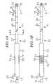
- Figure 1A is a side view of an electrophysiology guiding catheter with ultrasoundimaging capability with an electrophysiology catheter within the guiding catheter and two thumbslides for steering the guiding catheter;
- Figure 1B is a side view of an electrophysiology guiding catheter with ultrasound imagingcapability with an electrophysiology catheter within the guiding catheter and four thumb slides(only three of which are shown) for steering the guiding catheter;
- Figure 2 is a cross sectional view of a portion of the catheter tip and a distal portion of thesecond transitional tip;
- Figure 3 is a longitudinal cross sectional view of the catheter tip depicting theelectrophysiology catheter exit hole;
- Figure 4 is a cross sectional view of the guiding catheter body;
- FIG 5 is a longitudinal cross sectional view of the electrophysiology guiding catheterbody tip;
- FIG 6A is a cross sectional view depicting the upper half of a portion of theelectrophysiology guiding catheter body having a thumb slide; and,
- Figure 6B is a schematic top view of the portion of the electrophysiology guiding catheterbody having a thumb slide.
- The present invention is an electrophysiology guiding catheter with an ultrasoundimaging capability in combination with an electrophysiology catheter as defined in claim 1. Referring toFigure 1, a guiding
catheter 10 constructed in accordance with the present invention is illustrated.It is suitable for use as a visualization mechanism for visualizing an endocardial ablation site andfor simultaneously deploying an electrophysiology catheter for accessory pathway diagnosis andablation. - The guiding
catheter 10 comprises three primary components. The guiding catheter body11 defines a central lumen 30 (shown and described with reference to Figure 2) within which isguided anelectrophysiology catheter 15. Anultrasound transducer 18 is fixedly attached to thedistal end of the catheter body 11. In turn, the guiding catheter body 11 is fixedly attached at itsproximal end to a hub by conventional means. - . An
exit hole 14 is defined towards the distal end of the guiding catheter body 11 throughwhich theelectrophysiology catheter 15 exits thecentral lumen 30. Theelectrophysiologycatheter 15 comprises atip electrode 16 at its distal end for mapping and/or ablating endocardial tissue and is mounted at its proximal end to acontrol handle 19. Preferably, theelectrophysiology catheter 15 is steerable by longitudinal movement of the control handle 19relative to the body of theelectrophysiology catheter 15. Aberrant conductive pathway signalscan be received from thetip electrode 16 and transmitted to a remote detector and displayed viamoldedelectronic connector 20. RF energy can be transmitted to thetip electrode 16 via aremote RF source also connected to the moldedconnector 20. An exemplary example of anelectrophysiology catheter suitable for use with the present invention is a steerable open lumencatheter as described in U.S. Patent No. 5,431,168 issued to Wilton W. Webster, Jr. on July 11,1995 and manufactured by Cordis Webster, Inc., Baldwin Park California.However, many other electrophysiology cathetercould be used. - The guiding catheter body 11 can be of any suitable length for intravascular insertion. Inthe described embodiment, a length of about 100 cm is used. Similarly, the
exit hole 14 can beof any suitable size to allow an electrophysiology catheter to exit the guiding catheter body 11.In the described embodiment, a size of 1 ± 0.8 mm(0.04 ± 0.03 inches) is used and the distance between thedistal edge of theexit hole 14 and the distal end of thecatheter tip 12 is approximately 2.5 cm. - An
ultrasound transducer 18 is fixedly attached to the distal end of the guiding catheterbody 11. Thetransducer 18 emits and receives ultrasound in a single direction in the samemanner as a transesophageal ultrasound unit. In addition, other visualization devices can beemployed, such as those used for endoscopy. The exact dimensions of thetransducer 18 are notcritical and any transducer of suitable construction can be employed. Preferably, the transduceris cylindrical with a rounded tip approximately 1 to 2 cm in length and has an outer diameter of about 4 to 4.2 mm (about 12 to 12.5 French) so as to form a continuous outer surface with the guiding catheter body11. In the described embodiment, an ultrasound transducer with a 64 element crystal and havingan outer diameter of 4 to 4.2 mm (12 to 12.5 French) is employed. Exemplary examples of an intra-lumenultrasound transducer suitable for use with the described invention are manufactured byEndosonics, or by Acuson, Inc., Mountain View California. - The guiding catheter body 11 comprises four main sections as follows (from proximal todistal end): a
main body 27; a firsttransitional portion 26, a secondtransitional portion 25 and the distal section orcatheter tip 12. Each of these four sections can be of any suitable construction anddimensions. - In the described embodiment, the four sections each comprise several layers (describedfurther herein below) of which some are described in U.S. Patent No. 5,045,072 to Castillo et al.,and U.S. patent No. 4,531,943 to Van Tassel et al.Each section has an outer jacket. The four sections cooperate to allow the guiding
catheter 10 to be maneuvered through a patient's vascular system and deflected once situatedwithin the heart. Consequently, each outer jacket has a different durometer (D) hardness asfollows: themain body 27 is about 65 D; the firsttransitional portion 26 is about 55 D; the secondtransitional portion 25 is about 40 D; and thecatheter tip 12 is 80 AE. Preferably, with the exception of thecatheter tip 12, the outer jacket is constructed of nylon (RTM) having the aforementioned hardness. Thecatheter tip 12 can be made from a polyether polyurethane formulation as described in U.S.Patent No. 5,045,072 to Castillo et al. - Referring to Figure 2, a cross-sectional view of the
catheter tip 12 and a distal portion ofthe secondtransitional section 25 are shown. For simplicity, theexit hole 14 has been omitted. Acentral lumen 30 is defined longitudinally through the guiding catheter body 11. Aninner liner 32 runs the length of the guiding catheter body 11 ending slightly proximal to the end of thecatheter tip 12 to define a distal catheter tipjoint section 29. In the described embodiment, thewidth of the distal catheter tipjoint section 29 is approximately 1 ± 0.8 mm (0.04 ± 0.03 inches) and theinnerliner 32 is preferably constructed of polytetrafluoroethylene (PTFE), also known as Teflon (RTM). - A
braided wire sleeve 34 also runs the length of the guiding catheter body 11 but only upthrough the secondtransitional section 25, ending slightly proximal to the end of the secondtransitional section 25 to form a proximal catheter tipjoint section 28. In the described embodiment,the width of the proximal catheter tipjoint section 28 is approximately 1 ± 0.8 mm (0.04 ± 0.03 inches) and thebraided wire sleeve 34 is preferably constructed of stainless steel. - Referring to Figure 3, a cross sectional view of the
catheter tip 12 showing theexit hole 14 is shown. A deflector 40 is located beginning at the distal edge of theexit hole 14 andcontinuing towards the opposite wall of thecatheter tip 12 in the proximal direction to therebyform an inclined surface 41. The deflector 40 causes theelectrophysiology catheter 15 to deflectand exit thecatheter tip 12 when traveling distally relative to the guiding catheter body 11. - The deflector 40 can be of any suitable construction and in the described embodiment hasapproximately the same outer diameter as the
central lumen 30. Also, the deflector 40 ispreferably constructed of a smooth plastic material such as PTFE or polyurethane. The inclinedsurface 41 can be at an angle suitable for deflecting theelectrophysiology catheter 15. In thedescribed embodiment, the angle for deflection is from about 10 degrees to about 60 degrees. - A cross sectional view of the guiding catheter body 11 taken along line 4-4 of Figure 1 isshown in Figure 4. With the exceptions as indicated herein, the construction of each of the four sections comprising the guiding catheter body 11 is substantially similar and involves thefollowing layers. The innermost layer is an
inner liner 32, preferably constructed of PTFE, anddefining acentral lumen 30 running longitudinally its entire length. - In the described embodiment, the
central lumen 30 has an inner diameter of about 2.8 mm (0.110inches). Preferably, theinner liner 32 defines twolongitudinal grooves 36 on its outer surface atopposite sides from each other. A pair of smallpuller wire tubes 33 are situated in thegrooves 36 to maintain their orientation. Preferably, thepuller wire tubes 33 are constructed ofpolyamide with an inner diameter of approximately 0.3 mm (0.012 inches).Puller wires 21 run axiallywithin thepuller wire tubes 33. Thepuller wires 21 have a diameter of about 0.25 mm (0.01 inches). Thepuller wires 21 are constructed ofstainless steel cable 50 with aPTFE sleeve 51 covering them toprovide lubricity within thepolyamide tubes 33. - A
layer 35 of eight braidedribbon cables 53 runs longitudinally along either side of thepuller wire tubes 33 and is arranged to surround theinner liner 32. In the described embodiment,the 64 element crystal for theultrasound transducer 18 requires 64 lead wires. Thus, the braidedribbon cable layer 35 preferably comprises eight ribbon cables bundled together and each havingeightindividual microcoax wires 52 of about 0.2 mm (8 mils) thickness. Thebraided wire sleeve 34 runslongitudinally over thepuller wire tubes 33 and the braidedribbon cables layer 35. Preferably,the braided wire sleeve is constructed of stainless steel. Finally, the above-describedouter jacket 127, preferably constructed of nylon (RTM), surrounds the braidedwire sleeve layer 34. - Referring to FIG 5, a longitudinal cross sectional view of the catheter tip 12is shown.The
transducer 18 is fixably attached to the distal end of thecatheter tip 12 by conventional means. A circular marker band 17 is also fixedly attached about thecatheter tip 12 at a slightdistance proximal to the catheter tip. In the preferred embodiment, the marker band isembedded between theinner liner 32 and thecable layer 35. The marker band 17 is for assistinga practitioner in locating the orientation of the catheter tip within a patient's body. In thedescribed embodiment, the marker band 17 is about 1 cm from the end of thetransducer 18. Themarker band 17 can be of any suitable construction, however, in the described embodiment,platinum or a platinum-iridium alloy is used. In a preferred embodiment, the marker band alsoserves as a location for mounting the puller wire ends as described below. In an alternateembodiment, themarker band 117 may be fixedly attached to the outer surface of the catheter tipas shown in Figure 1A. - The
catheter tip 12 is steerable using the pair ofpuller wires 21. To aid in steering, eachof the puller wires is connected to athumb slide 70 which is slidably mounted on the outersurface of the handle, preferably proximate to its distal end (FIGS. 1A, 6A, 6B). The pair of thumbslides are positioned opposite each other on thehandle 73. Preferably, the slides are positionedwithinrecessions 74 on the handle outer surface. - Sliding of the thumb slides in the proximal direction relative to the catheter pulls on thepuller wire to which it is connected and causes the
catheter tip 12 to deflect in a horizontaldirection. The deflection is such that thecatheter tip 12 becomes concave on the side of thepuller wire that was moved proximally. Reverse deflection of the catheter tip occurs by slidingthe opposite thumb slide proximally relative to the guiding catheter. Deflection of thecathetertip 12 is required to align the ultrasound vector beam for accurately visualizing the ablation site.Consequently, bidirectional movement in a left-right horizontal plane is achieved using the thumb slides 70 which are connected to pullerwires 21. In the described embodiment, thecatheter tip 12 is capable of 1 to 4 movement degrees of freedom. As it would become obviousto one skilled in the art, the embodiment comprising a single puller wire only requires a singlethumb slide. - In FIGS. 6A and 6B, the
puller wires 21 are preferably connected to the thumb slides viaaset screw 92. Theset screw 92 is threaded inside thethumb slide 70 through anopening 94 onthe thumb slide bottom. Eachpuller wire 21 exits itstube 33 and is routed through a centralorifice on the set screw so that aportion 97 of thewire 21 protrudes beyond the set screw.The set screw is then threaded onto the thumb slide until it jams thewire portion 97 extendingbeyond the set screw against the thumb slide, thereby forming a connection between the pullerwire and the thumb slide. - Each thumb slide slides within a
slit 91 formed on eachrecession 74 on the handle. Pairsofdepressions 93 are formed on therecession 74 on either side of the slit. A pair ofprotrusions 95 extending from a bottom surface of the thumb slide engage a pair of the depressions and lockthe slide in position. Extra force must be applied against the thumb slide to disengage it from thedepressions. The depressions are strategically located to lock the thumb slide in a distal,proximal or intermediate position. - Additionally, in a further embodiment (not shown), two additional puller wires and twoadditional puller wire polyamide tubes are located 90° relative to the left-
right puller wires 21 toenable movement of thecatheter tip 12 in an up-down (vertical) plane. The additional pullerwires are connected to two additional thumb slides which are located at 90° relative to the othertwo thumb slides (fig. 1B). - The
central lumen 30 is capable of accepting anelectrode electrophysiology catheter 15fed in from the distal end of the hub. In the described embodiment, an electrophysiologycatheter with a 2.6 mm (eight French) outer diameter is preferred. - Construction of the guiding catheter body 11 is as follows: First, the
inner liner 32 isplaced on a mandrel. The pair oflongitudinal grooves 36 are formed 180° apart along the lengthof theinner liner 32. The pair ofpuller wire tubes 33 are placed within thelongitudinal grooves 36. Thebraided ribbon cables 53 are pulled and placed in position over theinner liner 32. Thebraidedribbon cables layer 35 is completed by the addition of aflexible filler material 54,preferably a plastic such as polyurethane or similar material. Thebraided wire sleeve 34 ispulled over the assembly and the appropriateouter jacket 127 is pulled over thebraided wiresleeve 34 to complete construction. The entire assembly is removed from the mandrel and, usinga vertical fusing device, theouter jacket 127 is heat shrunk into place. - In use, a cardiologist would advance the guiding
catheter 10 with theelectrophysiologycatheter 15 inside the assembly from a remote site such as the femoral artery or vein into theheart. The cardiologist would have the ultrasound transducer connected to a conventionalultrasound machine that provides the needed electronic transmission to the transducer anddisplays the feedback from the transducer on an appropriate display means. The cardiologistwould constantly monitor the position of the guiding catheter as it advances into the heart. - Once the guiding catheter is in a heart chamber of interest, either an atrium or a ventricle,the cardiologist would then advance the electrophysiology catheter distally relative to the guidingcatheter such that the electrophysiology catheter exits out the exit hole and moves distally pastthe transducer. The cardiologist would use the steering means of the electrophysiology catheter to steer the
catheter tip 12 appropriately. As apparent from the drawings, the electrophysiologycatheter exits from the guiding catheter at an angle away from the guiding catheter that is thesame angle as the deflector. The cardiologist would steer the electrophysiology catheterback towards the guiding catheter as the electrophysiology catheter is advanced distally. Additionally,the cardiologist would use the puller wires in the guiding catheter to steer the guiding catheter ina direction towards the electrophysiology catheter. Eventually, the cardiologist would have theelectrophysiology catheter in line with the transducer of the guiding catheter such that theultrasound display means displays the location of the electrophysiology catheter within the heartchamber of interest. - The cardiologist would than electrically map areas of the endocardium to precisely locatethe accessory pathways with the electrophysiology catheter. Once an accessory pathway has beenidentified and properly mapped, the cardiologist would use the ultrasound transducer of theguiding catheter to properly image the area of the heart. The cardiologist can then learn about thedepth of the myocardium at interest, other anatomical structures, and whether any cardiac arteriesor veins are located nearby. Once proper ultrasound imaging has been performed, thecardiologist would then place the distal tip electrode of the electrophysiology catheter at theablation site. RF energy would then be delivered to the distal tip electrode of theelectrophysiology catheter for an appropriate amount of time. The ablation of the heart tissuewould also be constantly monitored by the cardiologist using the ultrasound transducer, the areaof tissue death being observable. This way the cardiologist can apply enough RF energy to ablatethe accessory pathway, but still limit the amount of RF energy to prevent over-ablation which cancause cardiac perforation or thrombosis of a vessel near by.
- Thus, the present invention provides a particularly useful safety feature in that acardiologist using the ultrasound imaging of the guiding catheter while performing ablation withthe electrophysiology catheter would prevent making lesions that are too deep, would preventsurface epicardial vessel thrombosis due to heating a cardiac artery or vein, would preventcardiac perforation from ablating the entire thickness of the heart wall, and would verify that anablation is occurring or has taken place.
- Although this invention has been described in certain specific embodiments, manyadditional modifications and variations will be apparent to those skilled in the art. It is,therefore, understood that within the scope of the appended claims, this invention may bepracticed otherwise then specifically described.
Claims (7)
- A steerable guiding catheter (10) in combination with an electrophysiology catheter(15),
the guiding catheter (10) comprising:the electrophysiology catheter (15) being slidably disposed within said lumen (30)and being elongated and flexible;an elongated tubing body (11) having a proximal end and a distalend and defining a lumen (30) extending for substantially the entire lengthof the tubing body (11) for receiving an electrophysiology catheter (15);a flexible tip (12) attached to the distal end of the tubing body (11);second and third lumens extending lengthwise through the tubingbody (11) and both being offset from the central axis of the tubing body(11);first and second puller wires (21 ) extending through and slidablydisposed in said second and third lumens, respectively, each said puller wire(21) being fixedly attached to a distal end of the flexible tip (12) at aposition on opposite sides of the central axis of the tubing body (11); andcontrol means (70) attached to the proximal ends of the puller wires(21) for moving the puller wires (21 ) longitudinally relative to the catheterbody (11) to thereby deflect the flexible tip (12) of the guiding catheter(10);
wherein the guiding catheter (10) has an ultrasound imaging distal tip comprising anultrasonic transducer (18) mounted on the flexible tip (12) of the tubing body (11) totransmit ultrasound energy and receive resultant echoes so as to provide visualization of anablation site, and
an electrical conductor is disposed in the tubing body (11) for electricallyconnecting the ultrasound transducer to control circuitry external of the steerable guidingcatheter; and
wherein the electrophysiology catheter (15) is also steerable. - The combination of a steerable guiding catheter (10) and an electrophysiologycatheter (15) as defined in claim 1, wherein the tubing body (11) includes:a fourth lumen extending lengthwise through the tubing body (11) and being offsetfrom the central axis of the tubing body (11); andthe electrical conductor extends through the fourth lumen and is connected to theultrasonic transducer (18).
- The combination of a steerable guiding catheter (10) and an electrophysiologycatheter (15) as defined in claim 1, wherein the tubing body (11) includes eight braidedribbon cables (53) that run longitudinally along the tubing body (11) and each being offsetfrom the central axis of the tubing body (11).
- The combination of a steerable guiding catheter (10) and an electrophysiologycatheter (15) as defined in claim 3, wherein each braided ribbon cable (53) has eightindividual microcoax wires (52).
- The combination of a steerable guiding catheter (10) and an electrophysiologycatheter (15) as defined in any one of the preceding claims, wherein the tubing body (11)comprises a main body (27), a first transitional portion (26) being of a lower durometerthan the main body (27) extending distally from the main body (27), a second transitionalportion (25) being of a lower durometer than the first transitional portion (26) andextending distally from the first transitional portion (26), and the flexible tip (12) being ofa lower durometer than the second transitional portion (25) and extending distally fromsaid second transitional portion (25).
- The combination of a steerable guiding catheter (10) and an electrophysiologycatheter (15) as defined in any one of the preceding claims, wherein the puller wires (21)are each connected to its own thumb slide (70) which is slidably mounted on the outersurface of a handle of the steerable guiding catheter (10) for steering the guiding catheter(10).
- The combination of a steerable guiding catheter (10) and an electrophysiologycatheter (15) as defined in any one of the preceding claims, wherein the electrophysiologycatheter (15) is steerable by longitudinal movement of a control handle (19) relative to thebody of the electrophysiology catheter (15).
Applications Claiming Priority (4)
| Application Number | Priority Date | Filing Date | Title |
|---|---|---|---|
| US649395P | 1995-11-09 | 1995-11-09 | |
| US6493 | 1995-11-09 | ||
| US723821 | 1996-09-30 | ||
| US08/723,821US5803083A (en) | 1995-11-09 | 1996-09-30 | Guiding catheter with ultrasound imaging capability |
Publications (2)
| Publication Number | Publication Date |
|---|---|
| EP0774232A1 EP0774232A1 (en) | 1997-05-21 |
| EP0774232B1true EP0774232B1 (en) | 2005-01-12 |
Family
ID=26675702
Family Applications (1)
| Application Number | Title | Priority Date | Filing Date |
|---|---|---|---|
| EP96308117AExpired - LifetimeEP0774232B1 (en) | 1995-11-09 | 1996-11-08 | Guiding catheter with ultrasound imaging capability in combination with an electrophysiology catheter |
Country Status (4)
| Country | Link |
|---|---|
| US (1) | US5803083A (en) |
| EP (1) | EP0774232B1 (en) |
| CA (1) | CA2189594C (en) |
| DE (1) | DE69634166T2 (en) |
Cited By (95)
| Publication number | Priority date | Publication date | Assignee | Title |
|---|---|---|---|---|
| DE102005045363A1 (en)* | 2005-09-22 | 2007-04-05 | Siemens Ag | Medical treatment device and associated operating method |
| US7384407B2 (en) | 2001-12-03 | 2008-06-10 | Ekos Corporation | Small vessel ultrasound catheter |
| US7708735B2 (en) | 2003-05-01 | 2010-05-04 | Covidien Ag | Incorporating rapid cooling in tissue fusion heating processes |
| US7722607B2 (en) | 2005-09-30 | 2010-05-25 | Covidien Ag | In-line vessel sealer and divider |
| US7771372B2 (en) | 2003-01-03 | 2010-08-10 | Ekos Corporation | Ultrasonic catheter with axial energy field |
| US7771425B2 (en) | 2003-06-13 | 2010-08-10 | Covidien Ag | Vessel sealer and divider having a variable jaw clamping mechanism |
| US7776037B2 (en) | 2006-07-07 | 2010-08-17 | Covidien Ag | System and method for controlling electrode gap during tissue sealing |
| US7776036B2 (en) | 2003-03-13 | 2010-08-17 | Covidien Ag | Bipolar concentric electrode assembly for soft tissue fusion |
| US7774933B2 (en) | 2002-02-28 | 2010-08-17 | Ekos Corporation | Method of manufacturing ultrasound catheters |
| US7789878B2 (en) | 2005-09-30 | 2010-09-07 | Covidien Ag | In-line vessel sealer and divider |
| US7799028B2 (en) | 2004-09-21 | 2010-09-21 | Covidien Ag | Articulating bipolar electrosurgical instrument |
| US7799026B2 (en) | 2002-11-14 | 2010-09-21 | Covidien Ag | Compressible jaw configuration with bipolar RF output electrodes for soft tissue fusion |
| US7811283B2 (en) | 2003-11-19 | 2010-10-12 | Covidien Ag | Open vessel sealing instrument with hourglass cutting mechanism and over-ratchet safety |
| US7828798B2 (en) | 1997-11-14 | 2010-11-09 | Covidien Ag | Laparoscopic bipolar electrosurgical instrument |
| US7846161B2 (en) | 2005-09-30 | 2010-12-07 | Covidien Ag | Insulating boot for electrosurgical forceps |
| US7857812B2 (en) | 2003-06-13 | 2010-12-28 | Covidien Ag | Vessel sealer and divider having elongated knife stroke and safety for cutting mechanism |
| US7877852B2 (en) | 2007-09-20 | 2011-02-01 | Tyco Healthcare Group Lp | Method of manufacturing an end effector assembly for sealing tissue |
| US7879035B2 (en) | 2005-09-30 | 2011-02-01 | Covidien Ag | Insulating boot for electrosurgical forceps |
| US7877853B2 (en) | 2007-09-20 | 2011-02-01 | Tyco Healthcare Group Lp | Method of manufacturing end effector assembly for sealing tissue |
| US7887536B2 (en) | 1998-10-23 | 2011-02-15 | Covidien Ag | Vessel sealing instrument |
| US7909823B2 (en) | 2005-01-14 | 2011-03-22 | Covidien Ag | Open vessel sealing instrument |
| US7922718B2 (en) | 2003-11-19 | 2011-04-12 | Covidien Ag | Open vessel sealing instrument with cutting mechanism |
| US7922953B2 (en) | 2005-09-30 | 2011-04-12 | Covidien Ag | Method for manufacturing an end effector assembly |
| US7931649B2 (en) | 2002-10-04 | 2011-04-26 | Tyco Healthcare Group Lp | Vessel sealing instrument with electrical cutting mechanism |
| US7935052B2 (en) | 2004-09-09 | 2011-05-03 | Covidien Ag | Forceps with spring loaded end effector assembly |
| US7947041B2 (en) | 1998-10-23 | 2011-05-24 | Covidien Ag | Vessel sealing instrument |
| US7951150B2 (en) | 2005-01-14 | 2011-05-31 | Covidien Ag | Vessel sealer and divider with rotating sealer and cutter |
| US7955332B2 (en) | 2004-10-08 | 2011-06-07 | Covidien Ag | Mechanism for dividing tissue in a hemostat-style instrument |
| US7963965B2 (en) | 1997-11-12 | 2011-06-21 | Covidien Ag | Bipolar electrosurgical instrument for sealing vessels |
| US8016827B2 (en) | 2008-10-09 | 2011-09-13 | Tyco Healthcare Group Lp | Apparatus, system, and method for performing an electrosurgical procedure |
| US8034052B2 (en) | 2006-05-05 | 2011-10-11 | Covidien Ag | Apparatus and method for electrode thermosurgery |
| USD649249S1 (en) | 2007-02-15 | 2011-11-22 | Tyco Healthcare Group Lp | End effectors of an elongated dissecting and dividing instrument |
| US8070746B2 (en) | 2006-10-03 | 2011-12-06 | Tyco Healthcare Group Lp | Radiofrequency fusion of cardiac tissue |
| US8142473B2 (en) | 2008-10-03 | 2012-03-27 | Tyco Healthcare Group Lp | Method of transferring rotational motion in an articulating surgical instrument |
| US8162940B2 (en) | 2002-10-04 | 2012-04-24 | Covidien Ag | Vessel sealing instrument with electrical cutting mechanism |
| US8162973B2 (en) | 2008-08-15 | 2012-04-24 | Tyco Healthcare Group Lp | Method of transferring pressure in an articulating surgical instrument |
| US8192433B2 (en) | 2002-10-04 | 2012-06-05 | Covidien Ag | Vessel sealing instrument with electrical cutting mechanism |
| US8197479B2 (en) | 2008-12-10 | 2012-06-12 | Tyco Healthcare Group Lp | Vessel sealer and divider |
| US8211105B2 (en) | 1997-11-12 | 2012-07-03 | Covidien Ag | Electrosurgical instrument which reduces collateral damage to adjacent tissue |
| US8221416B2 (en) | 2007-09-28 | 2012-07-17 | Tyco Healthcare Group Lp | Insulating boot for electrosurgical forceps with thermoplastic clevis |
| US8235993B2 (en) | 2007-09-28 | 2012-08-07 | Tyco Healthcare Group Lp | Insulating boot for electrosurgical forceps with exohinged structure |
| US8236025B2 (en) | 2007-09-28 | 2012-08-07 | Tyco Healthcare Group Lp | Silicone insulated electrosurgical forceps |
| US8235992B2 (en) | 2007-09-28 | 2012-08-07 | Tyco Healthcare Group Lp | Insulating boot with mechanical reinforcement for electrosurgical forceps |
| US8241283B2 (en) | 2007-09-28 | 2012-08-14 | Tyco Healthcare Group Lp | Dual durometer insulating boot for electrosurgical forceps |
| US8241284B2 (en) | 2001-04-06 | 2012-08-14 | Covidien Ag | Vessel sealer and divider with non-conductive stop members |
| US8241282B2 (en) | 2006-01-24 | 2012-08-14 | Tyco Healthcare Group Lp | Vessel sealing cutting assemblies |
| US8251996B2 (en) | 2007-09-28 | 2012-08-28 | Tyco Healthcare Group Lp | Insulating sheath for electrosurgical forceps |
| US8257352B2 (en) | 2003-11-17 | 2012-09-04 | Covidien Ag | Bipolar forceps having monopolar extension |
| US8257387B2 (en) | 2008-08-15 | 2012-09-04 | Tyco Healthcare Group Lp | Method of transferring pressure in an articulating surgical instrument |
| US8267936B2 (en) | 2007-09-28 | 2012-09-18 | Tyco Healthcare Group Lp | Insulating mechanically-interfaced adhesive for electrosurgical forceps |
| US8267935B2 (en) | 2007-04-04 | 2012-09-18 | Tyco Healthcare Group Lp | Electrosurgical instrument reducing current densities at an insulator conductor junction |
| US8298232B2 (en) | 2006-01-24 | 2012-10-30 | Tyco Healthcare Group Lp | Endoscopic vessel sealer and divider for large tissue structures |
| US8298228B2 (en) | 1997-11-12 | 2012-10-30 | Coviden Ag | Electrosurgical instrument which reduces collateral damage to adjacent tissue |
| US8303582B2 (en) | 2008-09-15 | 2012-11-06 | Tyco Healthcare Group Lp | Electrosurgical instrument having a coated electrode utilizing an atomic layer deposition technique |
| US8303586B2 (en) | 2003-11-19 | 2012-11-06 | Covidien Ag | Spring loaded reciprocating tissue cutting mechanism in a forceps-style electrosurgical instrument |
| US8317787B2 (en) | 2008-08-28 | 2012-11-27 | Covidien Lp | Tissue fusion jaw angle improvement |
| US8348948B2 (en) | 2004-03-02 | 2013-01-08 | Covidien Ag | Vessel sealing system using capacitive RF dielectric heating |
| US8361071B2 (en) | 1999-10-22 | 2013-01-29 | Covidien Ag | Vessel sealing forceps with disposable electrodes |
| US8382754B2 (en) | 2005-03-31 | 2013-02-26 | Covidien Ag | Electrosurgical forceps with slow closure sealing plates and method of sealing tissue |
| US8454602B2 (en) | 2009-05-07 | 2013-06-04 | Covidien Lp | Apparatus, system, and method for performing an electrosurgical procedure |
| US8469956B2 (en) | 2008-07-21 | 2013-06-25 | Covidien Lp | Variable resistor jaw |
| US8469957B2 (en) | 2008-10-07 | 2013-06-25 | Covidien Lp | Apparatus, system, and method for performing an electrosurgical procedure |
| US8486107B2 (en) | 2008-10-20 | 2013-07-16 | Covidien Lp | Method of sealing tissue using radiofrequency energy |
| US8496656B2 (en) | 2003-05-15 | 2013-07-30 | Covidien Ag | Tissue sealer with non-conductive variable stop members and method of sealing tissue |
| US8523898B2 (en) | 2009-07-08 | 2013-09-03 | Covidien Lp | Endoscopic electrosurgical jaws with offset knife |
| US8535312B2 (en) | 2008-09-25 | 2013-09-17 | Covidien Lp | Apparatus, system and method for performing an electrosurgical procedure |
| US8591506B2 (en) | 1998-10-23 | 2013-11-26 | Covidien Ag | Vessel sealing system |
| US8597297B2 (en) | 2006-08-29 | 2013-12-03 | Covidien Ag | Vessel sealing instrument with multiple electrode configurations |
| US8623276B2 (en) | 2008-02-15 | 2014-01-07 | Covidien Lp | Method and system for sterilizing an electrosurgical instrument |
| US8636761B2 (en) | 2008-10-09 | 2014-01-28 | Covidien Lp | Apparatus, system, and method for performing an endoscopic electrosurgical procedure |
| US8641713B2 (en) | 2005-09-30 | 2014-02-04 | Covidien Ag | Flexible endoscopic catheter with ligasure |
| US8647341B2 (en) | 2003-06-13 | 2014-02-11 | Covidien Ag | Vessel sealer and divider for use with small trocars and cannulas |
| US8734443B2 (en) | 2006-01-24 | 2014-05-27 | Covidien Lp | Vessel sealer and divider for large tissue structures |
| US8764748B2 (en) | 2008-02-06 | 2014-07-01 | Covidien Lp | End effector assembly for electrosurgical device and method for making the same |
| US8784417B2 (en) | 2008-08-28 | 2014-07-22 | Covidien Lp | Tissue fusion jaw angle improvement |
| US8795274B2 (en) | 2008-08-28 | 2014-08-05 | Covidien Lp | Tissue fusion jaw angle improvement |
| US8852228B2 (en) | 2009-01-13 | 2014-10-07 | Covidien Lp | Apparatus, system, and method for performing an electrosurgical procedure |
| US8882766B2 (en) | 2006-01-24 | 2014-11-11 | Covidien Ag | Method and system for controlling delivery of energy to divide tissue |
| US8898888B2 (en) | 2009-09-28 | 2014-12-02 | Covidien Lp | System for manufacturing electrosurgical seal plates |
| US8968314B2 (en) | 2008-09-25 | 2015-03-03 | Covidien Lp | Apparatus, system and method for performing an electrosurgical procedure |
| US9023043B2 (en) | 2007-09-28 | 2015-05-05 | Covidien Lp | Insulating mechanically-interfaced boot and jaws for electrosurgical forceps |
| US9028493B2 (en) | 2009-09-18 | 2015-05-12 | Covidien Lp | In vivo attachable and detachable end effector assembly and laparoscopic surgical instrument and methods therefor |
| US9095347B2 (en) | 2003-11-20 | 2015-08-04 | Covidien Ag | Electrically conductive/insulative over shoe for tissue fusion |
| US9107672B2 (en) | 1998-10-23 | 2015-08-18 | Covidien Ag | Vessel sealing forceps with disposable electrodes |
| US9113940B2 (en) | 2011-01-14 | 2015-08-25 | Covidien Lp | Trigger lockout and kickback mechanism for surgical instruments |
| US9149323B2 (en) | 2003-05-01 | 2015-10-06 | Covidien Ag | Method of fusing biomaterials with radiofrequency energy |
| US9375254B2 (en) | 2008-09-25 | 2016-06-28 | Covidien Lp | Seal and separate algorithm |
| US9848938B2 (en) | 2003-11-13 | 2017-12-26 | Covidien Ag | Compressible jaw configuration with bipolar RF output electrodes for soft tissue fusion |
| US10154848B2 (en) | 2011-07-11 | 2018-12-18 | Covidien Lp | Stand alone energy-based tissue clips |
| US10213250B2 (en) | 2015-11-05 | 2019-02-26 | Covidien Lp | Deployment and safety mechanisms for surgical instruments |
| US10303641B2 (en) | 2014-05-07 | 2019-05-28 | Covidien Lp | Authentication and information system for reusable surgical instruments |
| US10646267B2 (en) | 2013-08-07 | 2020-05-12 | Covidien LLP | Surgical forceps |
| US11166759B2 (en) | 2017-05-16 | 2021-11-09 | Covidien Lp | Surgical forceps |
| USD956973S1 (en) | 2003-06-13 | 2022-07-05 | Covidien Ag | Movable handle for endoscopic vessel sealer and divider |
| US11844562B2 (en) | 2020-03-23 | 2023-12-19 | Covidien Lp | Electrosurgical forceps for grasping, treating, and/or dividing tissue |
Families Citing this family (127)
| Publication number | Priority date | Publication date | Assignee | Title |
|---|---|---|---|---|
| US6302875B1 (en)* | 1996-10-11 | 2001-10-16 | Transvascular, Inc. | Catheters and related devices for forming passageways between blood vessels or other anatomical structures |
| US6375615B1 (en) | 1995-10-13 | 2002-04-23 | Transvascular, Inc. | Tissue penetrating catheters having integral imaging transducers and their methods of use |
| EP0873722A1 (en)* | 1997-04-24 | 1998-10-28 | Sulzer Osypka GmbH | Apparatus for an endocardiac treatment |
| US6171277B1 (en)* | 1997-12-01 | 2001-01-09 | Cordis Webster, Inc. | Bi-directional control handle for steerable catheter |
| US6006137A (en)* | 1998-03-06 | 1999-12-21 | Medtronic, Inc. | Method for single elecrode bi-atrial pacing |
| US5948009A (en)* | 1998-03-06 | 1999-09-07 | Tu; Hosheng | Apparatus and methods for medical ablation use |
| US6178354B1 (en) | 1998-12-02 | 2001-01-23 | C. R. Bard, Inc. | Internal mechanism for displacing a slidable electrode |
| US6162179A (en)* | 1998-12-08 | 2000-12-19 | Scimed Life Systems, Inc. | Loop imaging catheter |
| WO2000067825A1 (en)* | 1999-05-07 | 2000-11-16 | Microheart, Inc. | Apparatus and method for delivering therapeutic and diagnostic agents |
| US7147633B2 (en) | 1999-06-02 | 2006-12-12 | Boston Scientific Scimed, Inc. | Method and apparatus for treatment of atrial fibrillation |
| DE60031272T2 (en) | 1999-06-02 | 2007-05-31 | Boston Scientific Ltd., St. Michael | Drug delivery device |
| US6451016B1 (en) | 1999-07-12 | 2002-09-17 | C. R. Bard, Inc. | Displaceable ablation electrode |
| US6551337B1 (en) | 1999-10-05 | 2003-04-22 | Omnisonics Medical Technologies, Inc. | Ultrasonic medical device operating in a transverse mode |
| US20040097996A1 (en) | 1999-10-05 | 2004-05-20 | Omnisonics Medical Technologies, Inc. | Apparatus and method of removing occlusions using an ultrasonic medical device operating in a transverse mode |
| US6524251B2 (en) | 1999-10-05 | 2003-02-25 | Omnisonics Medical Technologies, Inc. | Ultrasonic device for tissue ablation and sheath for use therewith |
| US6456890B2 (en) | 2000-05-15 | 2002-09-24 | Pacesetter, Inc. | Lead with polymeric tubular liner for guidewire and stylet insertion |
| US6456889B2 (en) | 2000-05-15 | 2002-09-24 | Pacesetter, Inc. | Lead with polymeric tubular liner for guidewire and stylet insertion |
| WO2002070158A1 (en)* | 2001-03-07 | 2002-09-12 | Omnisonics Medical Technologies, Inc. | Apparatus and method for manufacturing small diameter medical devices |
| US6610058B2 (en) | 2001-05-02 | 2003-08-26 | Cardiac Pacemakers, Inc. | Dual-profile steerable catheter |
| JP2003169806A (en)* | 2001-12-05 | 2003-06-17 | Olympus Optical Co Ltd | Ultrasonic probe |
| US20080146943A1 (en)* | 2006-12-14 | 2008-06-19 | Ep Medsystems, Inc. | Integrated Beam Former And Isolation For An Ultrasound Probe |
| US20080146925A1 (en)* | 2006-12-14 | 2008-06-19 | Ep Medsystems, Inc. | Integrated Electrophysiology and Ultrasound Imaging System |
| US7074189B1 (en)* | 2002-01-23 | 2006-07-11 | Valentino Montegrande | Endoscopically deliverable ultrasound imaging system and method of use |
| US20040082859A1 (en)* | 2002-07-01 | 2004-04-29 | Alan Schaer | Method and apparatus employing ultrasound energy to treat body sphincters |
| US6709396B2 (en)* | 2002-07-17 | 2004-03-23 | Vermon | Ultrasound array transducer for catheter use |
| US7211045B2 (en)* | 2002-07-22 | 2007-05-01 | Ep Medsystems, Inc. | Method and system for using ultrasound in cardiac diagnosis and therapy |
| US6755790B2 (en) | 2002-10-14 | 2004-06-29 | Medtronic, Inc. | Transseptal access tissue thickness sensing dilator devices and methods for fabricating and using same |
| US7662099B2 (en)* | 2003-06-30 | 2010-02-16 | Ethicon, Inc. | Method and instrumentation to sense thermal lesion formation by ultrasound imaging |
| US7077089B2 (en)* | 2003-08-15 | 2006-07-18 | Kohler Company | Oil drainback system for internal combustion engine |
| US7229437B2 (en)* | 2003-09-22 | 2007-06-12 | St. Jude Medical, Atrial Fibrillation Division, Inc. | Medical device having integral traces and formed electrodes |
| US8147486B2 (en)* | 2003-09-22 | 2012-04-03 | St. Jude Medical, Atrial Fibrillation Division, Inc. | Medical device with flexible printed circuit |
| US7234225B2 (en)* | 2003-09-22 | 2007-06-26 | St. Jude Medical, Atrial Fibrillation Division, Inc. | Method for manufacturing medical device having embedded traces and formed electrodes |
| CA2551831A1 (en)* | 2004-01-29 | 2005-08-11 | Ekos Corporation | Small vessel ultrasound catheter |
| US7794414B2 (en) | 2004-02-09 | 2010-09-14 | Emigrant Bank, N.A. | Apparatus and method for an ultrasonic medical device operating in torsional and transverse modes |
| US8628519B2 (en) | 2004-09-17 | 2014-01-14 | The Spectranetics Corporation | Rapid exchange bias laser catheter design |
| US8545488B2 (en)* | 2004-09-17 | 2013-10-01 | The Spectranetics Corporation | Cardiovascular imaging system |
| US7713210B2 (en)* | 2004-11-23 | 2010-05-11 | St. Jude Medical, Atrial Fibrillation Division, Inc. | Method and apparatus for localizing an ultrasound catheter |
| US9623265B2 (en)* | 2005-04-07 | 2017-04-18 | Boston Scientific Scimed, Inc. | Device for controlled tissue treatment |
| US20090118612A1 (en) | 2005-05-06 | 2009-05-07 | Sorin Grunwald | Apparatus and Method for Vascular Access |
| US20070016069A1 (en) | 2005-05-06 | 2007-01-18 | Sorin Grunwald | Ultrasound sensor |
| US20060270976A1 (en)* | 2005-05-31 | 2006-11-30 | Prorhythm, Inc. | Steerable catheter |
| US20060270975A1 (en)* | 2005-05-31 | 2006-11-30 | Prorhythm, Inc. | Steerable catheter |
| JP2009500086A (en)* | 2005-07-01 | 2009-01-08 | ハンセン メディカル,インク. | Robotic guide catheter system |
| US20070021744A1 (en)* | 2005-07-07 | 2007-01-25 | Creighton Francis M Iv | Apparatus and method for performing ablation with imaging feedback |
| US8954134B2 (en) | 2005-09-13 | 2015-02-10 | Children's Medical Center Corporation | Light-guided transluminal catheter |
| US20070073160A1 (en) | 2005-09-13 | 2007-03-29 | Children's Medical Center Corporation | Light-guided transluminal catheter |
| EP1951354A4 (en)* | 2005-11-08 | 2010-09-29 | Custom Med Applications Inc | Reinforced catheter with articulated distal tip |
| US9833595B2 (en)* | 2005-12-30 | 2017-12-05 | Biosense Webster, Inc. | Dual-lever bi-directional handle |
| US8840560B2 (en)* | 2006-04-04 | 2014-09-23 | Volcano Corporation | Ultrasound catheter and hand-held device for manipulating a transducer on the catheter's distal end |
| US10499937B2 (en) | 2006-05-19 | 2019-12-10 | Recor Medical, Inc. | Ablation device with optimized input power profile and method of using the same |
| US9867530B2 (en) | 2006-08-14 | 2018-01-16 | Volcano Corporation | Telescopic side port catheter device with imaging system and method for accessing side branch occlusions |
| US20080146940A1 (en)* | 2006-12-14 | 2008-06-19 | Ep Medsystems, Inc. | External and Internal Ultrasound Imaging System |
| JP5660890B2 (en) | 2007-06-26 | 2015-01-28 | バソノバ・インコーポレイテッドVasonova, Inc. | Vascular access and guidance system |
| US8864675B2 (en) | 2007-06-28 | 2014-10-21 | W. L. Gore & Associates, Inc. | Catheter |
| US8285362B2 (en)* | 2007-06-28 | 2012-10-09 | W. L. Gore & Associates, Inc. | Catheter with deflectable imaging device |
| EP2164407A4 (en)* | 2007-06-28 | 2012-07-11 | Gore Enterprise Holdings Inc | Improved catheter |
| US8852112B2 (en) | 2007-06-28 | 2014-10-07 | W. L. Gore & Associates, Inc. | Catheter with deflectable imaging device and bendable electrical conductor |
| EP2178442B1 (en) | 2007-07-12 | 2017-09-06 | Volcano Corporation | Catheter for in vivo imaging |
| US9596993B2 (en) | 2007-07-12 | 2017-03-21 | Volcano Corporation | Automatic calibration systems and methods of use |
| WO2009009802A1 (en) | 2007-07-12 | 2009-01-15 | Volcano Corporation | Oct-ivus catheter for concurrent luminal imaging |
| EP2227284A2 (en)* | 2007-12-20 | 2010-09-15 | Bayer Schering Pharma Aktiengesellschaft | Catheter having a core wire and low profile bond |
| US9603652B2 (en) | 2008-08-21 | 2017-03-28 | Covidien Lp | Electrosurgical instrument including a sensor |
| US8388647B2 (en) | 2009-10-28 | 2013-03-05 | Covidien Lp | Apparatus for tissue sealing |
| KR101673574B1 (en) | 2009-10-30 | 2016-11-07 | 레코 메디컬, 인코포레이티드 | Method and apparatus for treatment of hypertension through percutaneous ultrasound renal denervation |
| EP2637568B1 (en) | 2010-11-08 | 2017-04-12 | Vasonova, Inc. | Endovascular navigation system |
| US11141063B2 (en) | 2010-12-23 | 2021-10-12 | Philips Image Guided Therapy Corporation | Integrated system architectures and methods of use |
| US11040140B2 (en) | 2010-12-31 | 2021-06-22 | Philips Image Guided Therapy Corporation | Deep vein thrombosis therapeutic methods |
| CN102068308B (en)* | 2011-03-02 | 2012-08-08 | 黄晶 | Gradient array ultrasonic imaging guidance ablation catheter |
| US9360630B2 (en) | 2011-08-31 | 2016-06-07 | Volcano Corporation | Optical-electrical rotary joint and methods of use |
| EP2846701A4 (en) | 2012-05-07 | 2016-01-27 | Vasonova Inc | Right atrium indicator |
| US10070827B2 (en) | 2012-10-05 | 2018-09-11 | Volcano Corporation | Automatic image playback |
| US9324141B2 (en) | 2012-10-05 | 2016-04-26 | Volcano Corporation | Removal of A-scan streaking artifact |
| US20140100454A1 (en) | 2012-10-05 | 2014-04-10 | Volcano Corporation | Methods and systems for establishing parameters for three-dimensional imaging |
| US10568586B2 (en) | 2012-10-05 | 2020-02-25 | Volcano Corporation | Systems for indicating parameters in an imaging data set and methods of use |
| US9286673B2 (en) | 2012-10-05 | 2016-03-15 | Volcano Corporation | Systems for correcting distortions in a medical image and methods of use thereof |
| US9858668B2 (en) | 2012-10-05 | 2018-01-02 | Volcano Corporation | Guidewire artifact removal in images |
| US9367965B2 (en) | 2012-10-05 | 2016-06-14 | Volcano Corporation | Systems and methods for generating images of tissue |
| US11272845B2 (en) | 2012-10-05 | 2022-03-15 | Philips Image Guided Therapy Corporation | System and method for instant and automatic border detection |
| CA2887421A1 (en) | 2012-10-05 | 2014-04-10 | David Welford | Systems and methods for amplifying light |
| US9292918B2 (en) | 2012-10-05 | 2016-03-22 | Volcano Corporation | Methods and systems for transforming luminal images |
| US9307926B2 (en) | 2012-10-05 | 2016-04-12 | Volcano Corporation | Automatic stent detection |
| US9840734B2 (en) | 2012-10-22 | 2017-12-12 | Raindance Technologies, Inc. | Methods for analyzing DNA |
| EP2931132B1 (en) | 2012-12-13 | 2023-07-05 | Philips Image Guided Therapy Corporation | System for targeted cannulation |
| EP2934311B1 (en) | 2012-12-20 | 2020-04-15 | Volcano Corporation | Smooth transition catheters |
| US11406498B2 (en) | 2012-12-20 | 2022-08-09 | Philips Image Guided Therapy Corporation | Implant delivery system and implants |
| US10942022B2 (en) | 2012-12-20 | 2021-03-09 | Philips Image Guided Therapy Corporation | Manual calibration of imaging system |
| EP2934310A4 (en) | 2012-12-20 | 2016-10-12 | Nathaniel J Kemp | Optical coherence tomography system that is reconfigurable between different imaging modes |
| WO2014113188A2 (en) | 2012-12-20 | 2014-07-24 | Jeremy Stigall | Locating intravascular images |
| US10939826B2 (en) | 2012-12-20 | 2021-03-09 | Philips Image Guided Therapy Corporation | Aspirating and removing biological material |
| EP2936241B1 (en) | 2012-12-21 | 2020-10-21 | Nathaniel J. Kemp | Power-efficient optical buffering using a polarisation-maintaining active optical switch |
| JP2016501625A (en) | 2012-12-21 | 2016-01-21 | ジェローム マイ, | Ultrasound imaging with variable line density |
| US10332228B2 (en) | 2012-12-21 | 2019-06-25 | Volcano Corporation | System and method for graphical processing of medical data |
| EP2934323A4 (en) | 2012-12-21 | 2016-08-17 | Andrew Hancock | SYSTEM AND METHOD FOR MULTIPLE PROCESSING OF IMAGE SIGNALS |
| US9486143B2 (en) | 2012-12-21 | 2016-11-08 | Volcano Corporation | Intravascular forward imaging device |
| US10413317B2 (en) | 2012-12-21 | 2019-09-17 | Volcano Corporation | System and method for catheter steering and operation |
| US10058284B2 (en) | 2012-12-21 | 2018-08-28 | Volcano Corporation | Simultaneous imaging, monitoring, and therapy |
| JP2016507892A (en) | 2012-12-21 | 2016-03-10 | デイビッド ウェルフォード, | System and method for narrowing the wavelength emission of light |
| CA2895769A1 (en) | 2012-12-21 | 2014-06-26 | Douglas Meyer | Rotational ultrasound imaging catheter with extended catheter body telescope |
| US9612105B2 (en) | 2012-12-21 | 2017-04-04 | Volcano Corporation | Polarization sensitive optical coherence tomography system |
| US10226597B2 (en) | 2013-03-07 | 2019-03-12 | Volcano Corporation | Guidewire with centering mechanism |
| WO2014138555A1 (en) | 2013-03-07 | 2014-09-12 | Bernhard Sturm | Multimodal segmentation in intravascular images |
| US20140276923A1 (en) | 2013-03-12 | 2014-09-18 | Volcano Corporation | Vibrating catheter and methods of use |
| EP2967391A4 (en) | 2013-03-12 | 2016-11-02 | Donna Collins | SYSTEMS AND METHODS FOR DIAGNOSING CORONARY MICROVASCULAR DISEASE |
| US9623211B2 (en) | 2013-03-13 | 2017-04-18 | The Spectranetics Corporation | Catheter movement control |
| WO2014159819A1 (en) | 2013-03-13 | 2014-10-02 | Jinhyoung Park | System and methods for producing an image from a rotational intravascular ultrasound device |
| US9301687B2 (en) | 2013-03-13 | 2016-04-05 | Volcano Corporation | System and method for OCT depth calibration |
| US11026591B2 (en) | 2013-03-13 | 2021-06-08 | Philips Image Guided Therapy Corporation | Intravascular pressure sensor calibration |
| US12343198B2 (en) | 2013-03-14 | 2025-07-01 | Philips Image Guided Therapy Corporation | Delivery catheter having imaging capabilities |
| US11642169B2 (en) | 2013-03-14 | 2023-05-09 | The Spectranetics Corporation | Smart multiplexed medical laser system |
| US10292677B2 (en) | 2013-03-14 | 2019-05-21 | Volcano Corporation | Endoluminal filter having enhanced echogenic properties |
| US20160030151A1 (en) | 2013-03-14 | 2016-02-04 | Volcano Corporation | Filters with echogenic characteristics |
| US9757200B2 (en) | 2013-03-14 | 2017-09-12 | The Spectranetics Corporation | Intelligent catheter |
| EP2971232A1 (en) | 2013-03-14 | 2016-01-20 | ReCor Medical, Inc. | Methods of plating or coating ultrasound transducers |
| US10219887B2 (en) | 2013-03-14 | 2019-03-05 | Volcano Corporation | Filters with echogenic characteristics |
| WO2014159276A1 (en) | 2013-03-14 | 2014-10-02 | Recor Medical, Inc. | Ultrasound-based neuromodulation system |
| US10758308B2 (en) | 2013-03-14 | 2020-09-01 | The Spectranetics Corporation | Controller to select optical channel parameters in a catheter |
| US10987168B2 (en) | 2014-05-29 | 2021-04-27 | Spectranetics Llc | System and method for coordinated laser delivery and imaging |
| US10646274B2 (en) | 2014-12-30 | 2020-05-12 | Regents Of The University Of Minnesota | Laser catheter with use of reflected light and force indication to determine material type in vascular system |
| US10646118B2 (en) | 2014-12-30 | 2020-05-12 | Regents Of The University Of Minnesota | Laser catheter with use of reflected light to determine material type in vascular system |
| US10646275B2 (en) | 2014-12-30 | 2020-05-12 | Regents Of The University Of Minnesota | Laser catheter with use of determined material type in vascular system in ablation of material |
| US11497889B2 (en)* | 2018-08-23 | 2022-11-15 | Nuvera Medical, Inc. | Medical tool positioning devices, systems, and methods of use and manufacture |
| US20200297307A1 (en)* | 2019-03-20 | 2020-09-24 | Avent, Inc. | Catheter with Seal Layer |
| US11730349B2 (en)* | 2019-10-25 | 2023-08-22 | Canon U.S.A., Inc. | Steerable medical device with bending sections and improved connector therefor |
| CN111685798A (en)* | 2020-05-28 | 2020-09-22 | 广州新诚生物科技有限公司 | Catheter integrating controllable circumferential ultrasonic scanning and steering functions |
| US20220160220A1 (en)* | 2020-11-23 | 2022-05-26 | Medos International Sárl | Arthroscopic medical implements and assemblies |
| US11779362B1 (en)* | 2022-08-01 | 2023-10-10 | Truvue, Inc. | Methods and apparatus for true lumen re-entry |
| US20250072863A1 (en)* | 2023-08-30 | 2025-03-06 | Boston Scientific Scimed, Inc. | Intravascular Ultrasound Catheter |
Citations (3)
| Publication number | Priority date | Publication date | Assignee | Title |
|---|---|---|---|---|
| US5045072A (en)* | 1989-06-13 | 1991-09-03 | Cordis Corporation | Catheter having highly radiopaque, flexible tip |
| WO1993008738A1 (en)* | 1991-11-08 | 1993-05-13 | Mayo Foundation For Medical Education And Research | Transvascular ultrasound hemodynamic catheter and method |
| US5368564A (en)* | 1992-12-23 | 1994-11-29 | Angeion Corporation | Steerable catheter |
Family Cites Families (10)
| Publication number | Priority date | Publication date | Assignee | Title |
|---|---|---|---|---|
| US5370675A (en)* | 1992-08-12 | 1994-12-06 | Vidamed, Inc. | Medical probe device and method |
| US4582067A (en)* | 1983-02-14 | 1986-04-15 | Washington Research Foundation | Method for endoscopic blood flow detection by the use of ultrasonic energy |
| US4531943A (en)* | 1983-08-08 | 1985-07-30 | Angiomedics Corporation | Catheter with soft deformable tip |
| US4552554A (en)* | 1984-06-25 | 1985-11-12 | Medi-Tech Incorporated | Introducing catheter |
| US4769005A (en)* | 1987-08-06 | 1988-09-06 | Robert Ginsburg | Selective catheter guide |
| US5025778A (en)* | 1990-03-26 | 1991-06-25 | Opielab, Inc. | Endoscope with potential channels and method of using the same |
| US5545200A (en)* | 1993-07-20 | 1996-08-13 | Medtronic Cardiorhythm | Steerable electrophysiology catheter |
| US5431168A (en)* | 1993-08-23 | 1995-07-11 | Cordis-Webster, Inc. | Steerable open-lumen catheter |
| US5409000A (en)* | 1993-09-14 | 1995-04-25 | Cardiac Pathways Corporation | Endocardial mapping and ablation system utilizing separately controlled steerable ablation catheter with ultrasonic imaging capabilities and method |
| US5487385A (en)* | 1993-12-03 | 1996-01-30 | Avitall; Boaz | Atrial mapping and ablation catheter system |
- 1996
- 1996-09-30USUS08/723,821patent/US5803083A/ennot_activeExpired - Lifetime
- 1996-11-05CACA002189594Apatent/CA2189594C/ennot_activeExpired - Lifetime
- 1996-11-08EPEP96308117Apatent/EP0774232B1/ennot_activeExpired - Lifetime
- 1996-11-08DEDE69634166Tpatent/DE69634166T2/ennot_activeExpired - Lifetime
Patent Citations (3)
| Publication number | Priority date | Publication date | Assignee | Title |
|---|---|---|---|---|
| US5045072A (en)* | 1989-06-13 | 1991-09-03 | Cordis Corporation | Catheter having highly radiopaque, flexible tip |
| WO1993008738A1 (en)* | 1991-11-08 | 1993-05-13 | Mayo Foundation For Medical Education And Research | Transvascular ultrasound hemodynamic catheter and method |
| US5368564A (en)* | 1992-12-23 | 1994-11-29 | Angeion Corporation | Steerable catheter |
Cited By (156)
| Publication number | Priority date | Publication date | Assignee | Title |
|---|---|---|---|---|
| US8211105B2 (en) | 1997-11-12 | 2012-07-03 | Covidien Ag | Electrosurgical instrument which reduces collateral damage to adjacent tissue |
| US7963965B2 (en) | 1997-11-12 | 2011-06-21 | Covidien Ag | Bipolar electrosurgical instrument for sealing vessels |
| US8298228B2 (en) | 1997-11-12 | 2012-10-30 | Coviden Ag | Electrosurgical instrument which reduces collateral damage to adjacent tissue |
| US7828798B2 (en) | 1997-11-14 | 2010-11-09 | Covidien Ag | Laparoscopic bipolar electrosurgical instrument |
| US7947041B2 (en) | 1998-10-23 | 2011-05-24 | Covidien Ag | Vessel sealing instrument |
| US8591506B2 (en) | 1998-10-23 | 2013-11-26 | Covidien Ag | Vessel sealing system |
| US7896878B2 (en) | 1998-10-23 | 2011-03-01 | Coviden Ag | Vessel sealing instrument |
| US9107672B2 (en) | 1998-10-23 | 2015-08-18 | Covidien Ag | Vessel sealing forceps with disposable electrodes |
| US7887536B2 (en) | 1998-10-23 | 2011-02-15 | Covidien Ag | Vessel sealing instrument |
| US9375270B2 (en) | 1998-10-23 | 2016-06-28 | Covidien Ag | Vessel sealing system |
| US9375271B2 (en) | 1998-10-23 | 2016-06-28 | Covidien Ag | Vessel sealing system |
| US9463067B2 (en) | 1998-10-23 | 2016-10-11 | Covidien Ag | Vessel sealing system |
| US8361071B2 (en) | 1999-10-22 | 2013-01-29 | Covidien Ag | Vessel sealing forceps with disposable electrodes |
| US8241284B2 (en) | 2001-04-06 | 2012-08-14 | Covidien Ag | Vessel sealer and divider with non-conductive stop members |
| US10251696B2 (en) | 2001-04-06 | 2019-04-09 | Covidien Ag | Vessel sealer and divider with stop members |
| US10265121B2 (en) | 2001-04-06 | 2019-04-23 | Covidien Ag | Vessel sealer and divider |
| US10687887B2 (en) | 2001-04-06 | 2020-06-23 | Covidien Ag | Vessel sealer and divider |
| US7384407B2 (en) | 2001-12-03 | 2008-06-10 | Ekos Corporation | Small vessel ultrasound catheter |
| US7774933B2 (en) | 2002-02-28 | 2010-08-17 | Ekos Corporation | Method of manufacturing ultrasound catheters |
| US8162940B2 (en) | 2002-10-04 | 2012-04-24 | Covidien Ag | Vessel sealing instrument with electrical cutting mechanism |
| US10537384B2 (en) | 2002-10-04 | 2020-01-21 | Covidien Lp | Vessel sealing instrument with electrical cutting mechanism |
| US8740901B2 (en) | 2002-10-04 | 2014-06-03 | Covidien Ag | Vessel sealing instrument with electrical cutting mechanism |
| US8333765B2 (en) | 2002-10-04 | 2012-12-18 | Covidien Ag | Vessel sealing instrument with electrical cutting mechanism |
| US7931649B2 (en) | 2002-10-04 | 2011-04-26 | Tyco Healthcare Group Lp | Vessel sealing instrument with electrical cutting mechanism |
| US9585716B2 (en) | 2002-10-04 | 2017-03-07 | Covidien Ag | Vessel sealing instrument with electrical cutting mechanism |
| US8551091B2 (en) | 2002-10-04 | 2013-10-08 | Covidien Ag | Vessel sealing instrument with electrical cutting mechanism |
| US10987160B2 (en) | 2002-10-04 | 2021-04-27 | Covidien Ag | Vessel sealing instrument with cutting mechanism |
| US8192433B2 (en) | 2002-10-04 | 2012-06-05 | Covidien Ag | Vessel sealing instrument with electrical cutting mechanism |
| US8945125B2 (en) | 2002-11-14 | 2015-02-03 | Covidien Ag | Compressible jaw configuration with bipolar RF output electrodes for soft tissue fusion |
| US7799026B2 (en) | 2002-11-14 | 2010-09-21 | Covidien Ag | Compressible jaw configuration with bipolar RF output electrodes for soft tissue fusion |
| US7771372B2 (en) | 2003-01-03 | 2010-08-10 | Ekos Corporation | Ultrasonic catheter with axial energy field |
| US7776036B2 (en) | 2003-03-13 | 2010-08-17 | Covidien Ag | Bipolar concentric electrode assembly for soft tissue fusion |
| US9149323B2 (en) | 2003-05-01 | 2015-10-06 | Covidien Ag | Method of fusing biomaterials with radiofrequency energy |
| US8679114B2 (en) | 2003-05-01 | 2014-03-25 | Covidien Ag | Incorporating rapid cooling in tissue fusion heating processes |
| US7708735B2 (en) | 2003-05-01 | 2010-05-04 | Covidien Ag | Incorporating rapid cooling in tissue fusion heating processes |
| US8496656B2 (en) | 2003-05-15 | 2013-07-30 | Covidien Ag | Tissue sealer with non-conductive variable stop members and method of sealing tissue |
| USRE47375E1 (en) | 2003-05-15 | 2019-05-07 | Coviden Ag | Tissue sealer with non-conductive variable stop members and method of sealing tissue |
| US9492225B2 (en) | 2003-06-13 | 2016-11-15 | Covidien Ag | Vessel sealer and divider for use with small trocars and cannulas |
| US8647341B2 (en) | 2003-06-13 | 2014-02-11 | Covidien Ag | Vessel sealer and divider for use with small trocars and cannulas |
| USD956973S1 (en) | 2003-06-13 | 2022-07-05 | Covidien Ag | Movable handle for endoscopic vessel sealer and divider |
| US7857812B2 (en) | 2003-06-13 | 2010-12-28 | Covidien Ag | Vessel sealer and divider having elongated knife stroke and safety for cutting mechanism |
| US10918435B2 (en) | 2003-06-13 | 2021-02-16 | Covidien Ag | Vessel sealer and divider |
| US10278772B2 (en) | 2003-06-13 | 2019-05-07 | Covidien Ag | Vessel sealer and divider |
| US10842553B2 (en) | 2003-06-13 | 2020-11-24 | Covidien Ag | Vessel sealer and divider |
| US7771425B2 (en) | 2003-06-13 | 2010-08-10 | Covidien Ag | Vessel sealer and divider having a variable jaw clamping mechanism |
| US9848938B2 (en) | 2003-11-13 | 2017-12-26 | Covidien Ag | Compressible jaw configuration with bipolar RF output electrodes for soft tissue fusion |
| US8257352B2 (en) | 2003-11-17 | 2012-09-04 | Covidien Ag | Bipolar forceps having monopolar extension |
| US8597296B2 (en) | 2003-11-17 | 2013-12-03 | Covidien Ag | Bipolar forceps having monopolar extension |
| US10441350B2 (en) | 2003-11-17 | 2019-10-15 | Covidien Ag | Bipolar forceps having monopolar extension |
| US7922718B2 (en) | 2003-11-19 | 2011-04-12 | Covidien Ag | Open vessel sealing instrument with cutting mechanism |
| US8394096B2 (en) | 2003-11-19 | 2013-03-12 | Covidien Ag | Open vessel sealing instrument with cutting mechanism |
| US7811283B2 (en) | 2003-11-19 | 2010-10-12 | Covidien Ag | Open vessel sealing instrument with hourglass cutting mechanism and over-ratchet safety |
| US8303586B2 (en) | 2003-11-19 | 2012-11-06 | Covidien Ag | Spring loaded reciprocating tissue cutting mechanism in a forceps-style electrosurgical instrument |
| US8623017B2 (en) | 2003-11-19 | 2014-01-07 | Covidien Ag | Open vessel sealing instrument with hourglass cutting mechanism and overratchet safety |
| US9980770B2 (en) | 2003-11-20 | 2018-05-29 | Covidien Ag | Electrically conductive/insulative over-shoe for tissue fusion |
| US9095347B2 (en) | 2003-11-20 | 2015-08-04 | Covidien Ag | Electrically conductive/insulative over shoe for tissue fusion |
| US8348948B2 (en) | 2004-03-02 | 2013-01-08 | Covidien Ag | Vessel sealing system using capacitive RF dielectric heating |
| US7935052B2 (en) | 2004-09-09 | 2011-05-03 | Covidien Ag | Forceps with spring loaded end effector assembly |
| US7799028B2 (en) | 2004-09-21 | 2010-09-21 | Covidien Ag | Articulating bipolar electrosurgical instrument |
| US8366709B2 (en) | 2004-09-21 | 2013-02-05 | Covidien Ag | Articulating bipolar electrosurgical instrument |
| US7955332B2 (en) | 2004-10-08 | 2011-06-07 | Covidien Ag | Mechanism for dividing tissue in a hemostat-style instrument |
| US8123743B2 (en) | 2004-10-08 | 2012-02-28 | Covidien Ag | Mechanism for dividing tissue in a hemostat-style instrument |
| US7951150B2 (en) | 2005-01-14 | 2011-05-31 | Covidien Ag | Vessel sealer and divider with rotating sealer and cutter |
| US8147489B2 (en) | 2005-01-14 | 2012-04-03 | Covidien Ag | Open vessel sealing instrument |
| US7909823B2 (en) | 2005-01-14 | 2011-03-22 | Covidien Ag | Open vessel sealing instrument |
| US8382754B2 (en) | 2005-03-31 | 2013-02-26 | Covidien Ag | Electrosurgical forceps with slow closure sealing plates and method of sealing tissue |
| DE102005045363A1 (en)* | 2005-09-22 | 2007-04-05 | Siemens Ag | Medical treatment device and associated operating method |
| US7892232B2 (en) | 2005-09-22 | 2011-02-22 | Siemens Aktiengesellschaft | Medical treatment device and associated method of operation |
| US9579145B2 (en) | 2005-09-30 | 2017-02-28 | Covidien Ag | Flexible endoscopic catheter with ligasure |
| US8394095B2 (en) | 2005-09-30 | 2013-03-12 | Covidien Ag | Insulating boot for electrosurgical forceps |
| US7879035B2 (en) | 2005-09-30 | 2011-02-01 | Covidien Ag | Insulating boot for electrosurgical forceps |
| US9549775B2 (en) | 2005-09-30 | 2017-01-24 | Covidien Ag | In-line vessel sealer and divider |
| USRE44834E1 (en) | 2005-09-30 | 2014-04-08 | Covidien Ag | Insulating boot for electrosurgical forceps |
| US8361072B2 (en) | 2005-09-30 | 2013-01-29 | Covidien Ag | Insulating boot for electrosurgical forceps |
| US7922953B2 (en) | 2005-09-30 | 2011-04-12 | Covidien Ag | Method for manufacturing an end effector assembly |
| US8668689B2 (en) | 2005-09-30 | 2014-03-11 | Covidien Ag | In-line vessel sealer and divider |
| US7846161B2 (en) | 2005-09-30 | 2010-12-07 | Covidien Ag | Insulating boot for electrosurgical forceps |
| US7789878B2 (en) | 2005-09-30 | 2010-09-07 | Covidien Ag | In-line vessel sealer and divider |
| US8197633B2 (en) | 2005-09-30 | 2012-06-12 | Covidien Ag | Method for manufacturing an end effector assembly |
| US8641713B2 (en) | 2005-09-30 | 2014-02-04 | Covidien Ag | Flexible endoscopic catheter with ligasure |
| US7722607B2 (en) | 2005-09-30 | 2010-05-25 | Covidien Ag | In-line vessel sealer and divider |
| US9918782B2 (en) | 2006-01-24 | 2018-03-20 | Covidien Lp | Endoscopic vessel sealer and divider for large tissue structures |
| US9539053B2 (en) | 2006-01-24 | 2017-01-10 | Covidien Lp | Vessel sealer and divider for large tissue structures |
| US9113903B2 (en) | 2006-01-24 | 2015-08-25 | Covidien Lp | Endoscopic vessel sealer and divider for large tissue structures |
| US8882766B2 (en) | 2006-01-24 | 2014-11-11 | Covidien Ag | Method and system for controlling delivery of energy to divide tissue |
| US8734443B2 (en) | 2006-01-24 | 2014-05-27 | Covidien Lp | Vessel sealer and divider for large tissue structures |
| US8241282B2 (en) | 2006-01-24 | 2012-08-14 | Tyco Healthcare Group Lp | Vessel sealing cutting assemblies |
| US8298232B2 (en) | 2006-01-24 | 2012-10-30 | Tyco Healthcare Group Lp | Endoscopic vessel sealer and divider for large tissue structures |
| US8034052B2 (en) | 2006-05-05 | 2011-10-11 | Covidien Ag | Apparatus and method for electrode thermosurgery |
| US7776037B2 (en) | 2006-07-07 | 2010-08-17 | Covidien Ag | System and method for controlling electrode gap during tissue sealing |
| US8597297B2 (en) | 2006-08-29 | 2013-12-03 | Covidien Ag | Vessel sealing instrument with multiple electrode configurations |
| US8070746B2 (en) | 2006-10-03 | 2011-12-06 | Tyco Healthcare Group Lp | Radiofrequency fusion of cardiac tissue |
| USD649249S1 (en) | 2007-02-15 | 2011-11-22 | Tyco Healthcare Group Lp | End effectors of an elongated dissecting and dividing instrument |
| US8267935B2 (en) | 2007-04-04 | 2012-09-18 | Tyco Healthcare Group Lp | Electrosurgical instrument reducing current densities at an insulator conductor junction |
| US7877852B2 (en) | 2007-09-20 | 2011-02-01 | Tyco Healthcare Group Lp | Method of manufacturing an end effector assembly for sealing tissue |
| US7877853B2 (en) | 2007-09-20 | 2011-02-01 | Tyco Healthcare Group Lp | Method of manufacturing end effector assembly for sealing tissue |
| US8235992B2 (en) | 2007-09-28 | 2012-08-07 | Tyco Healthcare Group Lp | Insulating boot with mechanical reinforcement for electrosurgical forceps |
| US8241283B2 (en) | 2007-09-28 | 2012-08-14 | Tyco Healthcare Group Lp | Dual durometer insulating boot for electrosurgical forceps |
| US8251996B2 (en) | 2007-09-28 | 2012-08-28 | Tyco Healthcare Group Lp | Insulating sheath for electrosurgical forceps |
| US9554841B2 (en) | 2007-09-28 | 2017-01-31 | Covidien Lp | Dual durometer insulating boot for electrosurgical forceps |
| US8696667B2 (en) | 2007-09-28 | 2014-04-15 | Covidien Lp | Dual durometer insulating boot for electrosurgical forceps |
| US9023043B2 (en) | 2007-09-28 | 2015-05-05 | Covidien Lp | Insulating mechanically-interfaced boot and jaws for electrosurgical forceps |
| US8267936B2 (en) | 2007-09-28 | 2012-09-18 | Tyco Healthcare Group Lp | Insulating mechanically-interfaced adhesive for electrosurgical forceps |
| US8221416B2 (en) | 2007-09-28 | 2012-07-17 | Tyco Healthcare Group Lp | Insulating boot for electrosurgical forceps with thermoplastic clevis |
| US8235993B2 (en) | 2007-09-28 | 2012-08-07 | Tyco Healthcare Group Lp | Insulating boot for electrosurgical forceps with exohinged structure |
| US8236025B2 (en) | 2007-09-28 | 2012-08-07 | Tyco Healthcare Group Lp | Silicone insulated electrosurgical forceps |
| US8764748B2 (en) | 2008-02-06 | 2014-07-01 | Covidien Lp | End effector assembly for electrosurgical device and method for making the same |
| US8623276B2 (en) | 2008-02-15 | 2014-01-07 | Covidien Lp | Method and system for sterilizing an electrosurgical instrument |
| US9247988B2 (en) | 2008-07-21 | 2016-02-02 | Covidien Lp | Variable resistor jaw |
| US9113905B2 (en) | 2008-07-21 | 2015-08-25 | Covidien Lp | Variable resistor jaw |
| US8469956B2 (en) | 2008-07-21 | 2013-06-25 | Covidien Lp | Variable resistor jaw |
| US8257387B2 (en) | 2008-08-15 | 2012-09-04 | Tyco Healthcare Group Lp | Method of transferring pressure in an articulating surgical instrument |
| US8162973B2 (en) | 2008-08-15 | 2012-04-24 | Tyco Healthcare Group Lp | Method of transferring pressure in an articulating surgical instrument |
| US8317787B2 (en) | 2008-08-28 | 2012-11-27 | Covidien Lp | Tissue fusion jaw angle improvement |
| US8784417B2 (en) | 2008-08-28 | 2014-07-22 | Covidien Lp | Tissue fusion jaw angle improvement |
| US8795274B2 (en) | 2008-08-28 | 2014-08-05 | Covidien Lp | Tissue fusion jaw angle improvement |
| US8303582B2 (en) | 2008-09-15 | 2012-11-06 | Tyco Healthcare Group Lp | Electrosurgical instrument having a coated electrode utilizing an atomic layer deposition technique |
| US9375254B2 (en) | 2008-09-25 | 2016-06-28 | Covidien Lp | Seal and separate algorithm |
| US8535312B2 (en) | 2008-09-25 | 2013-09-17 | Covidien Lp | Apparatus, system and method for performing an electrosurgical procedure |
| US8968314B2 (en) | 2008-09-25 | 2015-03-03 | Covidien Lp | Apparatus, system and method for performing an electrosurgical procedure |
| US8568444B2 (en) | 2008-10-03 | 2013-10-29 | Covidien Lp | Method of transferring rotational motion in an articulating surgical instrument |
| US8142473B2 (en) | 2008-10-03 | 2012-03-27 | Tyco Healthcare Group Lp | Method of transferring rotational motion in an articulating surgical instrument |
| US8469957B2 (en) | 2008-10-07 | 2013-06-25 | Covidien Lp | Apparatus, system, and method for performing an electrosurgical procedure |
| US8636761B2 (en) | 2008-10-09 | 2014-01-28 | Covidien Lp | Apparatus, system, and method for performing an endoscopic electrosurgical procedure |
| US8016827B2 (en) | 2008-10-09 | 2011-09-13 | Tyco Healthcare Group Lp | Apparatus, system, and method for performing an electrosurgical procedure |
| US9113898B2 (en) | 2008-10-09 | 2015-08-25 | Covidien Lp | Apparatus, system, and method for performing an electrosurgical procedure |
| US8486107B2 (en) | 2008-10-20 | 2013-07-16 | Covidien Lp | Method of sealing tissue using radiofrequency energy |
| US8197479B2 (en) | 2008-12-10 | 2012-06-12 | Tyco Healthcare Group Lp | Vessel sealer and divider |
| US9655674B2 (en) | 2009-01-13 | 2017-05-23 | Covidien Lp | Apparatus, system and method for performing an electrosurgical procedure |
| US8852228B2 (en) | 2009-01-13 | 2014-10-07 | Covidien Lp | Apparatus, system, and method for performing an electrosurgical procedure |
| US8858554B2 (en) | 2009-05-07 | 2014-10-14 | Covidien Lp | Apparatus, system, and method for performing an electrosurgical procedure |
| US10085794B2 (en) | 2009-05-07 | 2018-10-02 | Covidien Lp | Apparatus, system and method for performing an electrosurgical procedure |
| US8454602B2 (en) | 2009-05-07 | 2013-06-04 | Covidien Lp | Apparatus, system, and method for performing an electrosurgical procedure |
| US9345535B2 (en) | 2009-05-07 | 2016-05-24 | Covidien Lp | Apparatus, system and method for performing an electrosurgical procedure |
| US8523898B2 (en) | 2009-07-08 | 2013-09-03 | Covidien Lp | Endoscopic electrosurgical jaws with offset knife |
| US9931131B2 (en) | 2009-09-18 | 2018-04-03 | Covidien Lp | In vivo attachable and detachable end effector assembly and laparoscopic surgical instrument and methods therefor |
| US9028493B2 (en) | 2009-09-18 | 2015-05-12 | Covidien Lp | In vivo attachable and detachable end effector assembly and laparoscopic surgical instrument and methods therefor |
| US10188454B2 (en) | 2009-09-28 | 2019-01-29 | Covidien Lp | System for manufacturing electrosurgical seal plates |
| US11490955B2 (en) | 2009-09-28 | 2022-11-08 | Covidien Lp | Electrosurgical seal plates |
| US8898888B2 (en) | 2009-09-28 | 2014-12-02 | Covidien Lp | System for manufacturing electrosurgical seal plates |
| US11026741B2 (en) | 2009-09-28 | 2021-06-08 | Covidien Lp | Electrosurgical seal plates |
| US9750561B2 (en) | 2009-09-28 | 2017-09-05 | Covidien Lp | System for manufacturing electrosurgical seal plates |
| US9265552B2 (en) | 2009-09-28 | 2016-02-23 | Covidien Lp | Method of manufacturing electrosurgical seal plates |
| US10383649B2 (en) | 2011-01-14 | 2019-08-20 | Covidien Lp | Trigger lockout and kickback mechanism for surgical instruments |
| US9113940B2 (en) | 2011-01-14 | 2015-08-25 | Covidien Lp | Trigger lockout and kickback mechanism for surgical instruments |
| US11660108B2 (en) | 2011-01-14 | 2023-05-30 | Covidien Lp | Trigger lockout and kickback mechanism for surgical instruments |
| US10154848B2 (en) | 2011-07-11 | 2018-12-18 | Covidien Lp | Stand alone energy-based tissue clips |
| US10646267B2 (en) | 2013-08-07 | 2020-05-12 | Covidien LLP | Surgical forceps |
| US11144495B2 (en) | 2014-05-07 | 2021-10-12 | Covidien Lp | Authentication and information system for reusable surgical instruments |
| US10585839B2 (en) | 2014-05-07 | 2020-03-10 | Covidien Lp | Authentication and information system for reusable surgical instruments |
| US10303641B2 (en) | 2014-05-07 | 2019-05-28 | Covidien Lp | Authentication and information system for reusable surgical instruments |
| US11886373B2 (en) | 2014-05-07 | 2024-01-30 | Covidien Lp | Authentication and information system for reusable surgical instruments |
| US12282445B2 (en) | 2014-05-07 | 2025-04-22 | Covidien Lp | Authentication and information system for reusable surgical instruments |
| US10213250B2 (en) | 2015-11-05 | 2019-02-26 | Covidien Lp | Deployment and safety mechanisms for surgical instruments |
| US11166759B2 (en) | 2017-05-16 | 2021-11-09 | Covidien Lp | Surgical forceps |
| US11844562B2 (en) | 2020-03-23 | 2023-12-19 | Covidien Lp | Electrosurgical forceps for grasping, treating, and/or dividing tissue |
Also Published As
| Publication number | Publication date |
|---|---|
| DE69634166T2 (en) | 2006-01-19 |
| CA2189594C (en) | 2007-01-16 |
| DE69634166D1 (en) | 2005-02-17 |
| CA2189594A1 (en) | 1997-05-10 |
| US5803083A (en) | 1998-09-08 |
| EP0774232A1 (en) | 1997-05-21 |
Similar Documents
| Publication | Publication Date | Title |
|---|---|---|
| EP0774232B1 (en) | Guiding catheter with ultrasound imaging capability in combination with an electrophysiology catheter | |
| EP0900574B1 (en) | Handle for steerable DMR catheter | |
| US6360128B2 (en) | Cardiac mapping and ablation systems | |
| US6210362B1 (en) | Steerable catheter for detecting and revascularing ischemic myocardial tissue | |
| EP0900548B1 (en) | Steerable dmr catheter with infusion tube | |
| US5897529A (en) | Steerable deflectable catheter having improved flexibility | |
| US9078667B2 (en) | Catheter having reduced force concentration at tissue contact site | |
| US8657815B2 (en) | Delivery system for delivering a medical device to a location within a patient's body | |
| US5895417A (en) | Deflectable loop design for a linear lesion ablation apparatus | |
| EP0900549B1 (en) | Steerable direct myocardial revascularization catheter | |
| US5476495A (en) | Cardiac mapping and ablation systems | |
| US9241761B2 (en) | Ablation probe with ultrasonic imaging capability | |
| US6371955B1 (en) | Atrial branding iron catheter and a method for treating atrial fibrillation | |
| US7727230B2 (en) | Atrial ablation catheter and method for treating atrial fibrillation | |
| EP4031007B1 (en) | Catheter instrument with three pull wires | |
| US6235021B1 (en) | Ablation sheath | |
| WO2010009427A1 (en) | A positionable medical system for positioning medical components on or within a body | |
| EP1133264A1 (en) | Intracardiac grasp catheter | |
| JP4209003B2 (en) | Thin-walled catheter with high torsional rigidity | |
| US20010009986A1 (en) | Steerable catheter for detecting and revascularizing ischemic myocardial tissue | |
| US20210244360A1 (en) | Sensing, mapping, and therapy catheter with multiple catheterlets | |
| US11420019B2 (en) | Unibody intravascular catheter shaft |
Legal Events
| Date | Code | Title | Description |
|---|---|---|---|
| PUAI | Public reference made under article 153(3) epc to a published international application that has entered the european phase | Free format text:ORIGINAL CODE: 0009012 | |
| AK | Designated contracting states | Kind code of ref document:A1 Designated state(s):BE CH DE FR GB IE IT LI NL | |
| 17P | Request for examination filed | Effective date:19971027 | |
| 17Q | First examination report despatched | Effective date:20010821 | |
| GRAP | Despatch of communication of intention to grant a patent | Free format text:ORIGINAL CODE: EPIDOSNIGR1 | |
| RTI1 | Title (correction) | Free format text:GUIDING CATHETER WITH ULTRASOUND IMAGING CAPABILITY IN COMBINATION WITH AN ELECTROPHYSIOLOGY CATHETER | |
| GRAS | Grant fee paid | Free format text:ORIGINAL CODE: EPIDOSNIGR3 | |
| GRAA | (expected) grant | Free format text:ORIGINAL CODE: 0009210 | |
| AK | Designated contracting states | Kind code of ref document:B1 Designated state(s):BE CH DE FR GB IE IT LI NL | |
| PG25 | Lapsed in a contracting state [announced via postgrant information from national office to epo] | Ref country code:LI Free format text:LAPSE BECAUSE OF FAILURE TO SUBMIT A TRANSLATION OF THE DESCRIPTION OR TO PAY THE FEE WITHIN THE PRESCRIBED TIME-LIMIT Effective date:20050112 Ref country code:IT Free format text:LAPSE BECAUSE OF FAILURE TO SUBMIT A TRANSLATION OF THE DESCRIPTION OR TO PAY THE FEE WITHIN THE PRE;WARNING: LAPSES OF ITALIAN PATENTS WITH EFFECTIVE DATE BEFORE 2007 MAY HAVE OCCURRED AT ANY TIME BEFORE 2007. THE CORRECT EFFECTIVE DATE MAY BE DIFFERENT FROM THE ONE RECORDED.SCRIBED TIME-LIMIT Effective date:20050112 Ref country code:FR Free format text:LAPSE BECAUSE OF NON-PAYMENT OF DUE FEES Effective date:20050112 Ref country code:CH Free format text:LAPSE BECAUSE OF FAILURE TO SUBMIT A TRANSLATION OF THE DESCRIPTION OR TO PAY THE FEE WITHIN THE PRESCRIBED TIME-LIMIT Effective date:20050112 Ref country code:BE Free format text:LAPSE BECAUSE OF FAILURE TO SUBMIT A TRANSLATION OF THE DESCRIPTION OR TO PAY THE FEE WITHIN THE PRESCRIBED TIME-LIMIT Effective date:20050112 | |
| REG | Reference to a national code | Ref country code:GB Ref legal event code:FG4D | |
| REG | Reference to a national code | Ref country code:CH Ref legal event code:EP | |
| REF | Corresponds to: | Ref document number:69634166 Country of ref document:DE Date of ref document:20050217 Kind code of ref document:P | |
| REG | Reference to a national code | Ref country code:IE Ref legal event code:FG4D | |
| REG | Reference to a national code | Ref country code:CH Ref legal event code:PL | |
| PG25 | Lapsed in a contracting state [announced via postgrant information from national office to epo] | Ref country code:IE Free format text:LAPSE BECAUSE OF NON-PAYMENT OF DUE FEES Effective date:20051108 | |
| PLBE | No opposition filed within time limit | Free format text:ORIGINAL CODE: 0009261 | |
| STAA | Information on the status of an ep patent application or granted ep patent | Free format text:STATUS: NO OPPOSITION FILED WITHIN TIME LIMIT | |
| 26N | No opposition filed | Effective date:20051013 | |
| EN | Fr: translation not filed | ||
| REG | Reference to a national code | Ref country code:IE Ref legal event code:MM4A | |
| PGFP | Annual fee paid to national office [announced via postgrant information from national office to epo] | Ref country code:DE Payment date:20151103 Year of fee payment:20 Ref country code:GB Payment date:20151104 Year of fee payment:20 | |
| PGFP | Annual fee paid to national office [announced via postgrant information from national office to epo] | Ref country code:NL Payment date:20151110 Year of fee payment:20 | |
| REG | Reference to a national code | Ref country code:DE Ref legal event code:R071 Ref document number:69634166 Country of ref document:DE | |
| REG | Reference to a national code | Ref country code:NL Ref legal event code:MK Effective date:20161107 | |
| REG | Reference to a national code | Ref country code:GB Ref legal event code:PE20 Expiry date:20161107 | |
| PG25 | Lapsed in a contracting state [announced via postgrant information from national office to epo] | Ref country code:GB Free format text:LAPSE BECAUSE OF EXPIRATION OF PROTECTION Effective date:20161107 |