EP0774223B1 - Deformable undermattress with ergonomic shape - Google Patents
Deformable undermattress with ergonomic shapeDownload PDFInfo
- Publication number
- EP0774223B1 EP0774223B1EP19960402431EP96402431AEP0774223B1EP 0774223 B1EP0774223 B1EP 0774223B1EP 19960402431EP19960402431EP 19960402431EP 96402431 AEP96402431 AEP 96402431AEP 0774223 B1EP0774223 B1EP 0774223B1
- Authority
- EP
- European Patent Office
- Prior art keywords
- flexible
- deformable
- divan base
- divan
- base according
- Prior art date
- Legal status (The legal status is an assumption and is not a legal conclusion. Google has not performed a legal analysis and makes no representation as to the accuracy of the status listed.)
- Expired - Lifetime
Links
- 230000000284resting effectEffects0.000claims1
- 230000007246mechanismEffects0.000description2
- 230000000052comparative effectEffects0.000description1
- 238000006073displacement reactionMethods0.000description1
- 210000000689upper legAnatomy0.000description1
Images

Classifications
- A—HUMAN NECESSITIES
- A47—FURNITURE; DOMESTIC ARTICLES OR APPLIANCES; COFFEE MILLS; SPICE MILLS; SUCTION CLEANERS IN GENERAL
- A47C—CHAIRS; SOFAS; BEDS
- A47C31/00—Details or accessories for chairs, beds, or the like, not provided for in other groups of this subclass, e.g. upholstery fasteners, mattress protectors, stretching devices for mattress nets
- A47C31/12—Means, e.g. measuring means, for adapting chairs, beds or mattresses to the shape or weight of persons
- A47C31/123—Means, e.g. measuring means, for adapting chairs, beds or mattresses to the shape or weight of persons for beds or mattresses
- A—HUMAN NECESSITIES
- A47—FURNITURE; DOMESTIC ARTICLES OR APPLIANCES; COFFEE MILLS; SPICE MILLS; SUCTION CLEANERS IN GENERAL
- A47C—CHAIRS; SOFAS; BEDS
- A47C20/00—Head-, foot- or like rests for beds, sofas or the like
- A47C20/04—Head-, foot- or like rests for beds, sofas or the like with adjustable inclination
- A47C20/041—Head-, foot- or like rests for beds, sofas or the like with adjustable inclination by electric motors
Definitions
- the inventionrelates to a deformable bed base at ergonomic profile with sleeping surfaces consist of a single support element which is flexible including at least the head and the foot can be lifted to take optimal shape for user comfort.
- Known articulated bed basesin particular bed bases slatted, have a number of parts independent recliners that rotate relative to a fixed frame with respect to their neighboring parts and which allow the sleeping part to take desired inclinations depending on the position of relaxation sought.
- the articulated partsare put in motion by one or more electric motors which change their orientation via connecting rods and pivoting levers.
- the most common use of these box springsconsists in raising the bust part, that is to say the head of the box so that the user is in semi-sitting position for example making it easier reading.
- Each of these independent partsconstitutes a rigid element of a sleeping plan and when certain of them are noted, it remains between the plans neighbors of inflections that affect the comfort of the bedding despite the presence of the mattress which reduces them.
- EP-A-0 632 985represents the state of the art on closer to the invention.
- the Applicanthas found a solution which consists in replace the known independent tilting parts, by a single flexible element which supports the mattress which extends over the entire length of the bed base, and which itself rests on lifting devices which are ergonomic profiles whose curvature corresponds to the optimal form sought for the relaxation of the body human.
- the subject of the inventionis therefore a deformable bed base at ergonomic profile including the bust part and / or the part leg-foot can be lifted to varying heights by articulated members operated by at least one motor, said box spring consisting of a flexible assembly serving as support for a mattress, which extends over the entire length of the box spring, and which rests on lifting members capable of maintain the flexible assembly at the desired height and with a continuous curvature with an ergonomic profile.
- the lifting members of the flexible assemblyconsists of profiled supports whose upper face is rounded and pivoting arms bearing under the underside of said profiled supports lift them above a rigid base so that the flexible set is applied to them and follows their profile round.
- the flexible assemblyis formed of two bands flexible side panels between which slats extend rigid or flexible, engaged in fixed end caps of place in place on the bands, and which rest on a rigid base.
- the flexible assemblyis formed of two rigid link chains hinged together.
- the flexible assemblyis formed a single flexible surface covering the entire width of the bed, above which extend slats engaged in end pieces fixed to said flexible surface.
- the profiled support of the bust part of the box springhas an ergonomic upper face of rounded shape with concavity facing upwards. He is wearing also two pins guided in a circular ramp to concavity facing upwards arranged near the center of the box spring, under its base.
- the profiled support of the leg-foot part of the box springhas an ergonomically shaped upper face rounded, the first part of which is concavely turned upwards, followed by a concavity part facing the bottom.
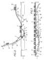
- the fixed frame 1a bed, fitted with side angles extending over the whole the length of the chassis, which constitute the support base rigid 2 of the deformable base.
- the latterconsists of two flexible side bands 3 which, in the position shown in Figure 1 rest horizontally on the base 2. On these strips are fixed from place to place at regular intervals or not of the ends 4 intended for receive transverse slats not shown on which rests the mattress.
- a larger slat 14 widthis additionally provided between the strips 3 at each end.
- the chest part of the box springis shown in left of the figures and the leg-foot part is on the right.
- a circular ramp 5AT proximity to the center of the base under each angle forming the base 2 is fixed a circular ramp 5 whose concavity is facing up.
- the rampis dug laterally of a channel 6 serving as a guide for two lugs 7 mounted at the end of a profiled support 8 which develops under the base to the left end of the box spring (figure 1).
- the circular ramp and the lugscould also use any other system capable of creating virtually (connecting rod system ..) or actually an axis hinge.
- said section 8has a very ergonomic, concave, rounded upper face turned upwards.
- profiled supportwhich is therefore below the strip flexible 3, and a fixed slat 9 connects the end of each profiles.
- control bar 10driven in rotation by a motor lever 11 under the action of a motor not shown.
- a arm 12terminated by a roller 13 which bears under the profile support 8.
- the motorturns the bar 10 which gradually raises the arms 12.
- the rollers 13provide lifting the profiled supports 8; this movement of pivoting causes the movement of the pins 7 to the interior of the channel 6 to the extreme position shown in FIG. 2. Due to the circular ramp 5, the pivoting movement of each profile support 8 is completed by a longitudinal sliding thereof in headboard direction.
- the fixed slat 9then protrudes from the slat end 14 of the bands 3, which avoids the overflow of the mattress with respect to the box spring.
- the leg-foot part visible on the right of the figuresalso has ergonomic supports 15 whose profile differs significantly from profile 8 in that it shows a first part AB with concavity turned upwards followed by a downwardly concavity BC part. These two parts correspond respectively to the support of user's thighs and feet.
- Profile support 15 visible in FIG. 1 in the erased position under the basecan pivot around a fixed horizontal axis 16 located substantially in the middle of the chassis near the ramp circular 5. Said profiled support rests by its face lower on a roller 17 mounted at the end of a pivoting arm 18 rotated by a cross bar of control 19, also operated by a motor lever 20.
- the lifting of the support ergonomic 15causes the displacement of the flexible strip 3 correspondent who will marry his profile as we see in Figure 2.
- pivoting parts previously describedare advantageously arranged on both sides of the base so to act simultaneously on the two lateral flexible bands 3.
- the flexible bands 3are replaced by rigid links articulated between them a bit like a chain of bicycle.
- the ends of the transverse slatsare fixed from place to place on the links.
- These link chainsconform to the profile of the ergonomic supports, completely like flexible tapes.
- the usercan obviously adjust to his suitability and independently the bust part and the part deformable box-leg.
- the box springwill always be supported on parts rounded with no inflection which improves comfort clearly.
- Figures 3 and 4illustrate a variant of realization of the leg-foot part of the box spring.
- a first pivoting lever 21is rotated by a control crossbar 22. It carries at its end a roller 23 which bears directly under the strip flexible 3.
- a second pivoting lever 24is articulated in a axis 25 on the end of the strip 3, and can rotate around a fixed point 26 secured to the chassis. The ends of two levers 21, 24 bent at their pivots are interconnected by a return rod 27.
- the cases described aboveare relate to mechanisms in which the flexible element supporting the mattress is formed by two bands flexible side panels.
- these bandscould be replaced by a single flexible surface that would cover the entire width of the bed.
- the end pieces 4would for example be stapled to the sides of said surface.
- the lifting bodieswould remain advantageously located on the sides of the bed.
- This flexible surfacehas the advantage, in particular, of hiding the mechanisms arranged on the chassis.
Landscapes
- Health & Medical Sciences (AREA)
- General Health & Medical Sciences (AREA)
- Nursing (AREA)
- Invalid Beds And Related Equipment (AREA)
- Devices For Medical Bathing And Washing (AREA)
Description
Translated fromFrenchL'invention se rapporte à un sommier déformable àprofil ergonomique dont les plans de couchage sontconstitués d'un unique élément support qui est souple dontau moins la tête et le pied sont relevables pour prendreune forme optimale en vue du confort de l'utilisateur.The invention relates to a deformable bed base atergonomic profile with sleeping surfacesconsist of a single support element which is flexible includingat least the head and the foot can be lifted to takeoptimal shape for user comfort.
Les sommiers articulés connus, notamment les sommiersà lattes, comportent un certain nombre partiesindépendantes inclinables qui pivotent par rapport à uncadre fixe par rapport à leurs parties voisines et quipermettent à la partie couchage de prendre desinclinaisons voulues en fonction de la position derelaxation recherchée. Les parties articulées sont misesen mouvement par un ou des moteurs électriques quimodifient leur orientation par l'intermédiaire de bielleset de leviers pivotants. L'usage le plus courant de cessommiers consiste à relever la partie buste, c'est-à-direla tête du sommier pour que l'utilisateur se trouve enposition semi-assise lui facilitant par exemple lalecture.Known articulated bed bases, in particular bed basesslatted, have a number of partsindependent recliners that rotate relative to afixed frame with respect to their neighboring parts and whichallow the sleeping part to takedesired inclinations depending on the position ofrelaxation sought. The articulated parts are putin motion by one or more electric motors whichchange their orientation via connecting rodsand pivoting levers. The most common use of thesebox springs consists in raising the bust part, that is to saythe head of the box so that the user is insemi-sitting position for example making it easierreading.
Chacune de ces parties indépendantes constitue unélément rigide d'un plan de couchage et quand certainesd'entre elles sont relevées, il subsiste entre les plansvoisins des inflexions qui nuisent au confort de laliterie malgré la présence du matelas qui les atténue.Each of these independent parts constitutes arigid element of a sleeping plan and when certainof them are noted, it remains between the plansneighbors of inflections that affect the comfort of thebedding despite the presence of the mattress which reduces them.
Il est apparent que la forme optimale que l'on puissedonner à un sommier pour un meilleur confort del'utilisateur, serait une forme continue, sans lignesbrisées, qui épouserait les lignes du corps humain quelque soit le degré de levage de la tête ou du pied de lit.It is apparent that the optimal form that we cangive a box spring for better comfortthe user, would be a continuous form, without linesbroken, which would fit the lines of the human body whatregardless of the degree of lifting of the head or footboard.
EP-A-0 632 985 représente l'état de la technique leplus proche de l'invention.EP-A-0 632 985 represents the state of the art oncloser to the invention.
La Demanderesse a trouvé une solution qui consiste àremplacer les parties inclinables indépendantes connues,par un unique élément souple servant de support au matelasqui s'étend sur toute la longueur du sommier, et quirepose lui-même sur des organes de relevage qui sont desprofilés ergonomiques dont la courbure correspond à la forme optimale recherchée pour la relaxation du corpshumain.The Applicant has found a solution which consists inreplace the known independent tilting parts,by a single flexible element which supports the mattresswhich extends over the entire length of the bed base, and whichitself rests on lifting devices which areergonomic profiles whose curvature corresponds to theoptimal form sought for the relaxation of the bodyhuman.
L'invention a donc pour objet un sommier déformable àprofil ergonomique dont la partie buste et/ou la partiejambe-pied est relevable à des hauteurs variables par desorganes articulés manoeuvrés par au moins un moteur, leditsommier étant constitué d'un ensemble souple servant desupport à un matelas, qui s'étend sur toute la longueur dusommier, et qui repose sur des organes de relevage aptes àmaintenir l'ensemble souple à la hauteur voulue et avecune courbure continue à profil ergonomique.The subject of the invention is therefore a deformable bed base atergonomic profile including the bust part and / or the partleg-foot can be lifted to varying heights byarticulated members operated by at least one motor, saidbox spring consisting of a flexible assembly serving assupport for a mattress, which extends over the entire length of thebox spring, and which rests on lifting members capable ofmaintain the flexible assembly at the desired height and witha continuous curvature with an ergonomic profile.
Selon l'invention, les organes de relevage del'ensemble souple sont constitués de supports profilésdont la face supérieure est arrondie et des bras pivotantsen appui sous la face inférieure desdits supports profilésles soulèvent au-dessus d'un socle rigide pour quel'ensemble souple s'applique sur eux et épouse leur profilarrondi.According to the invention, the lifting members ofthe flexible assembly consists of profiled supportswhose upper face is rounded and pivoting armsbearing under the underside of said profiled supportslift them above a rigid base so thatthe flexible set is applied to them and follows their profileround.
Selon une caractéristique particulière del'invention, l'ensemble souple est formé de deux bandeslatérales flexibles entre lesquelles s'étendent des lattesrigides ou souples, engagées dans des embouts fixés deplace en place sur les bandes, et qui reposent sur unsocle rigide.According to a particular characteristic ofthe invention, the flexible assembly is formed of two bandsflexible side panels between which slats extendrigid or flexible, engaged in fixed end caps ofplace in place on the bands, and which rest on arigid base.
En variante, l'ensemble souple est formé de deuxchaínes à maillons rigides articulés entre eux.Alternatively, the flexible assembly is formed of tworigid link chains hinged together.
Selon une autre variante, l'ensemble souple est forméd'une unique surface souple couvrant toute la largeur dulit, au-dessus de la quelle s'étendent des lattes engagéesdans des embouts fixés à ladite surface souple.According to another variant, the flexible assembly is formeda single flexible surface covering the entire width of thebed, above which extend slats engagedin end pieces fixed to said flexible surface.
Avantageusement le support profilé de la partie bustedu sommier présente une face supérieure ergonomique deforme arrondie à concavité tournée vers le haut. Il porteaussi deux ergots guidés dans une rampe circulaire àconcavité tournée vers le haut disposée à proximité ducentre du sommier, sous son socle. On peut aussi utiliser tout autre système capable de créer virtuellement ouréellement un axe d'articulation.Advantageously the profiled support of the bust partof the box spring has an ergonomic upper face ofrounded shape with concavity facing upwards. He is wearingalso two pins guided in a circular ramp toconcavity facing upwards arranged near thecenter of the box spring, under its base. We can also useany other system capable of creating virtually oractually an axis of articulation.
Selon une autre caractéristique particulière del'invention, le support profilé de la partie jambe-pied dusommier présente une face supérieure ergonomique de formearrondie dont une première partie est à concavité tournéevers le haut, suivie d'une partie à concavité tournée versle bas.According to another particular characteristic ofthe invention, the profiled support of the leg-foot part of thebox spring has an ergonomically shaped upper facerounded, the first part of which is concavely turnedupwards, followed by a concavity part facingthe bottom.
D'autres particularités etavantages de l'invention ressortiront de la descriptionsuivante d'une exemple de réalisation qui doit êtreconsidéré de façon non limitative et qui fait référence auxdessins annexés qui représentent :
On voit sur les figures 1 et 2 le châssis fixe 1d'un lit, équipé de cornières latérales s'étendant sur toutela longueur du châssis, qui constituent le socle-supportrigide 2 du sommier déformable. Ce dernier est constitué dedeux bandes latérale flexibles 3 qui, dans la positionreprésentée à la figure 1 reposent horizontalement sur lesocle 2. Sur ces bandes sont fixés de place en place àintervalles réguliers ou non des embouts 4 destinés àrecevoir des lattes transversales non représentées surlesquelles repose le matelas. Une latte 14 de plus grandelargeur est en outre prévue entre les bandes 3 à chaqueextrémité.We see in Figures 1 and 2 the fixed frame 1a bed, fitted with side angles extending over the wholethe length of the chassis, which constitute the support baserigid 2 of the deformable base. The latter consists oftwo
La partie buste du sommier est représentée àgauche des figures et la partie jambe-pied est à droite. Aproximité du centre du sommier sous chaque cornière formantle socle 2 est fixée une rampe circulaire 5 dont laconcavité est tournée vers le haut. La rampe est creuséelatéralement d'une rigole 6 servant de guide à deux ergots 7 montés à l'extrémité d'un support profilé 8 qui se développesous le socle jusqu'à l'extrémité gauche du sommier (figure1). En variante de la rampe circulaire et des ergots, onpourrait aussi utiliser tout autre système capable de créervirtuellement (système de bielles..) ou réellement un axed'articulation.The chest part of the box spring is shown inleft of the figures and the leg-foot part is on the right. ATproximity to the center of the base under each angle formingthe
On remarquera que ledit profilé 8 présente uneface supérieure arrondie très ergonomique à concavitétournée vers le haut. Il y a de chaque côté du lit un telsupport profilé qui se trouve donc au-dessous de la bandeflexible 3, et une latte fixe 9 relie l'extrémité de chacundes profilés.It will be noted that said
Par ailleurs, sur le châssis fixe est montéetransversalement une barre de commande 10 entraínée enrotation par un levier moteur 11 sous l'action d'un moteurnon représenté.Furthermore, on the fixed frame is mountedtransversely a
Sur chaque extrémité de la barre 10 est fixé unbras 12 terminé par un galet 13 qui prend appui sous lesupport profilé 8.On each end of the
Lorsque l'utilisateur veut assurer le relevage dela partie buste, le moteur fait tourner la barre 10 quirelève progressivement les bras 12. Les galets 13 assurentle relevage des supports profilés 8 ; ce mouvement depivotement entraíne le déplacement des ergots 7 àl'intérieur de la rigole 6 jusqu'à la position extrêmereprésentée à la figure 2. Du fait de la rampe circulaire 5,le mouvement de pivotement de chaque support profilé 8 estcomplété par un coulissement longitudinal de celui-ci endirection de la tête de lit.When the user wants to ensure the lifting ofthe bust part, the motor turns the
La latte fixe 9 dépasse alors de la latted'extrémité 14 des bandes 3, ce qui permet d'éviter ledébordement du matelas par rapport au sommier.The fixed slat 9 then protrudes from the
Au fur et à mesure de la rotation des supportsprofilés 8 qui sont des pièces rigides, les bandes flexibless'appliquent sur ces supports et épousent leur profilarrondi. Quel que soit le degré de relevage le buste del'utilisateur est parfaitement maintenu grâce à la formearrondie du sommier et du matelas qu'il supporte. Durant ce mouvement les galets 13 roulent sous les parties inférieuresdesdits profilés.As the supports
La partie jambe-pied visible à droite des figuresdispose également de supports ergonomiques 15 dont le profildiffère sensiblement du profil 8 dans la mesure où il montreune première partie AB à concavité tournée vers le hautsuivie d'une partie BC à concavité tournée vers le bas. Cesdeux parties correspondent à l'appui respectivement descuisses et des pieds de l'utilisateur. Le support profilé 15visible à la figure 1 en position effacée sous le socle,peut pivoter autour d'un axe fixe horizontal 16 localisésensiblement au milieu du châssis près de la rampecirculaire 5. Ledit support profilé repose par sa faceinférieure sur un galet 17 monté en bout d'un bras pivotant18 entraíné en rotation par une barre transversale decommande 19, également manoeuvrée par un levier moteur 20.The leg-foot part visible on the right of the figuresalso has
Comme pour la partie buste, le relevage du supportergonomique 15 entraíne le déplacement de la bande flexible3 correspondante qui va épouser son profil comme on le voità la figure 2.As for the bust part, the lifting of the supportergonomic 15 causes the displacement of the
Les pièces pivotantes précédemment décrites sontavantageusement disposées des deux côtés du sommier de façonà agir simultanément sur les deux bandes flexibles latérales3.The pivoting parts previously described areadvantageously arranged on both sides of the base soto act simultaneously on the two lateral
En variante de réalisation non représentée, lesbandes flexibles 3 sont remplacées par des maillons rigidesarticulés entre eux un peu à la manière d'une chaíne debicyclette. Les embouts des lattes transversales sont fixésde place en place sur les maillons. Ces chaínes à maillonsépousent le profil des supports ergonomiques, tout à faitcomme les bandes flexibles.As an alternative embodiment not shown, the
L'utilisateur peut bien évidemment régler à saconvenance et indépendamment la partie buste et la partiejambe-pied du sommier déformable.The user can obviously adjust to hissuitability and independently the bust part and the partdeformable box-leg.
Quelle que soit la hauteur donnée aux supportsprofilés, le sommier sera toujours en appui sur des partiesarrondies ne présentant pas d'inflexion ce qui améliorenettement le confort.Whatever the height given to the supportsprofiles, the box spring will always be supported on partsrounded with no inflection which improvescomfort clearly.
Les figures 3 et 4 illustrent une variante deréalisation de la partie jambe-pied du sommier.Figures 3 and 4 illustrate a variant ofrealization of the leg-foot part of the box spring.
Le support ergonomique précèdent est remplacé pardes leviers de commande qui exercent une précontrainte surla bande flexible. Dans le cas représenté il y en a deux. Unpremier levier pivotant 21 est entraíné en rotation par unebarre transversale de commande 22. Il porte à son extrémitéun galet 23 qui vient en appui directement sous la bandeflexible 3. Un second levier pivotant 24 s'articule selon unaxe 25 sur l'extrémité de la bande 3, et peut tourner autourd'un point fixe 26 solidaire du châssis. Les extrémités desdeux leviers 21, 24 coudées au niveau de leurs pivots sontreliées entre elles par une bielle de renvoi 27.The previous ergonomic support is replaced bycontrol levers which exert prestress onthe flexible band. In the case shown there are two. A
Dans la position de la figure 3 les levierspivotants se trouvent au-dessous du socle support rigide 2sur lequel repose la bande flexible 3.In the position of figure 3 the leversswivels are located below the
Dès qu'on fait agir le moteur dans le sens d'unerotation de la barre de commande 22, le levier pivotant 21va soulever par son galet 23 la bande flexible quis'infléchit vers le haut. Du fait de la bielle de renvoi 27,le mouvement se transmet à l'autre levier pivotant 24 quisoulève également l'extrémité de la bande flexible. Maiscelle-ci étant solidaire du levier par l'axe 25 subira unecontrainte qui va se traduire par une courbure entre sonextrémité et le galet 23 comme on le voit clairement à lafigure 4. La précontrainte exercée entre ces deux pointsd'appui maintiendra la cambrure arrondie de la bandeflexible donnant ainsi à la partie jambe-pied du sommier unprofil ergonomique équivalent à celui obtenu avec le supportprécédemment décrit.As soon as the engine is operated in the direction of arotation of the
Les cas de figure décrits précédemment serapportent à des mécanismes dans lesquels l'élément soupleservant de support au matelas est formé de deux bandeslatérales flexibles. En variante de réalisation nonreprésentée, ces bandes pourraient être remplacées par uneunique surface souple qui couvrirait toute la largeur dulit. Les embouts 4 seraient par exemple agrafés sur lescôtés de ladite surface. Les organes relevages resteraient avantageusement localisés sur les côtés du lit. Cettesurface souple présente l'avantage, notamment, d'occulterles mécanismes disposés sur le châssis.The cases described above arerelate to mechanisms in which the flexible elementsupporting the mattress is formed by two bandsflexible side panels. As an alternative embodimentshown, these bands could be replaced by asingle flexible surface that would cover the entire width of thebed. The
Claims (8)
- Deformable divan base with ergonomic profile, the chest part and/or theleg/foot part of which is adjustable to variable heights by articulatedmembers (21, 24, 27) operated by at least one motor, said divan base beingconstituted by a flexible assembly (3, 4, 14) serving as a support for amattress, which extends over the entire length of the divan base, and whichrests on raising members (8, 15, 21, 24) capable of keeping the flexibleassembly at the desired height and with a continuous curvature with anergonomic profile,characterised in that the raising members of the flexibleassembly (3, 4, 14) are constituted by shaped supports (8, 15), the upperface of which is rounded andin that pivoting arms (12, 18) bearing againstthe lower face of said shaped supports from below raise them above a rigidplinth (2) so that the flexible assembly (3) is applied over them and takes ontheir rounded profile.
- Deformable divan base according to Claim 1,characterised in that theflexible assembly is made of two flexible side strips (3) between which thereextend rigid or flexible slats engaged in the end pieces (4) fixed from placeto place on the strips, the flexible strips resting on a rigid plinth (2).
- Deformable divan base according to Claim 1,characterised in that theflexible assembly is made of two chains with rigid links articulated together.
- Deformable divan base according to Claim 1,characterised in that theflexible assembly is made of a single flexible surface covering the wholewidth of the bed, above which there extend slats engaged in end piecesfixed to said flexible surface.
- Deformable divan base according to Claim 1,characterised in that theshaped support (8) of the chest part of the divan base has an ergonomicupper face of rounded form with an upwards-facing concavity.
- Deformable divan base according to Claim 1,characterised in that theshaped support (8) of the chest part of the divan base carries two lugs (7)guided within a circular ramp (5) with an upwards-facing concavity,arranged near the centre of the divan base, under its plinth (2).
- Deformable divan base according to Claim 1,characterised in that theshaped support (15) of the leg/foot part of the divan base has an ergonomicupper face of rounded form, a first part (AB) of which has an upwards-facingconcavity, followed by a part (BC) with a downwards-facing concavity.
- Deformable divan base according to Claim 1,characterised in that thepivoting arms (12, 18) each end in a roller (13, 17) that rolls under thecorresponding shaped support (8, 15).
Applications Claiming Priority (2)
| Application Number | Priority Date | Filing Date | Title |
|---|---|---|---|
| FR9513463 | 1995-11-14 | ||
| FR9513463AFR2740953B1 (en) | 1995-11-14 | 1995-11-14 | DEFORMABLE BED WITH ERGONOMIC PROFILE |
Publications (2)
| Publication Number | Publication Date |
|---|---|
| EP0774223A1 EP0774223A1 (en) | 1997-05-21 |
| EP0774223B1true EP0774223B1 (en) | 2002-07-17 |
Family
ID=9484538
Family Applications (1)
| Application Number | Title | Priority Date | Filing Date |
|---|---|---|---|
| EP19960402431Expired - LifetimeEP0774223B1 (en) | 1995-11-14 | 1996-11-14 | Deformable undermattress with ergonomic shape |
Country Status (4)
| Country | Link |
|---|---|
| EP (1) | EP0774223B1 (en) |
| DE (1) | DE69622345T2 (en) |
| ES (1) | ES2180719T3 (en) |
| FR (1) | FR2740953B1 (en) |
Families Citing this family (11)
| Publication number | Priority date | Publication date | Assignee | Title |
|---|---|---|---|---|
| FR2767043B1 (en) | 1997-08-05 | 1999-10-29 | Oniris Sa | DEFORMABLE BED WITH A SLOPE AND ERGONOMIC PROFILE |
| FR2780256B1 (en)* | 1998-06-24 | 2000-08-25 | Epeda Sa | ADJUSTABLE BED SUMMER |
| FR2803500B1 (en) | 2000-01-06 | 2002-04-26 | Oniris Sa | SLEEPING PLAN OF A DEFORMABLE BED |
| FR2824714A1 (en)* | 2001-05-18 | 2002-11-22 | Michel Carteau | Flexible sun bed has thin longitudinal slats which can be raised and lowered by motorized arms |
| FR2828077A1 (en)* | 2001-08-01 | 2003-02-07 | Cie Des Matelas Epeda Et Merin | TPR RELAXATION SUMMER |
| DE20217759U1 (en)* | 2002-07-10 | 2004-04-01 | Cimosys Ag | Adjustment mechanism for the foot/head sections of a bed mattress or seat, and the like, has a swing setting lever within a side beam with projections acting on beam links, with support plane movements matching the human body |
| FR2878133B1 (en)* | 2004-11-24 | 2007-01-19 | Creations Andre Renault Soc Pa | ARTICULATED SOMMIER OF A NEW TYPE |
| NO336253B1 (en)* | 2011-10-21 | 2015-06-29 | Ekornes Asa | Adjustable bed |
| NO339707B1 (en)* | 2012-11-27 | 2017-01-23 | Ekornes Beds As | Adjustable bed |
| GB201610212D0 (en) | 2016-06-13 | 2016-07-27 | Motus Mech Ltd | Adjustable bed |
| GB201813009D0 (en) | 2018-08-09 | 2018-09-26 | Eevolv Ltd | A drive mechanism |
Family Cites Families (2)
| Publication number | Priority date | Publication date | Assignee | Title |
|---|---|---|---|---|
| DE8800360U1 (en)* | 1988-01-14 | 1988-05-26 | Niko Gesellschaft für Antriebstechnik mbH, 5253 Lindlar | Drive for slatted frames (II) |
| US5369826A (en)* | 1993-05-14 | 1994-12-06 | Paramount Bed Company Limited | Bottom structure of a bed |
- 1995
- 1995-11-14FRFR9513463Apatent/FR2740953B1/ennot_activeExpired - Fee Related
- 1996
- 1996-11-14EPEP19960402431patent/EP0774223B1/ennot_activeExpired - Lifetime
- 1996-11-14DEDE1996622345patent/DE69622345T2/ennot_activeExpired - Lifetime
- 1996-11-14ESES96402431Tpatent/ES2180719T3/ennot_activeExpired - Lifetime
Also Published As
| Publication number | Publication date |
|---|---|
| DE69622345T2 (en) | 2003-02-13 |
| FR2740953B1 (en) | 1998-01-23 |
| ES2180719T3 (en) | 2003-02-16 |
| DE69622345D1 (en) | 2002-08-22 |
| EP0774223A1 (en) | 1997-05-21 |
| FR2740953A1 (en) | 1997-05-16 |
Similar Documents
| Publication | Publication Date | Title |
|---|---|---|
| EP0788325B1 (en) | Device for tilting the top end and/or bottom end of a bed | |
| CA2064876C (en) | Bed base | |
| EP0774223B1 (en) | Deformable undermattress with ergonomic shape | |
| EP0835069B1 (en) | Undulatory motion relaxation device for furniture with a suspension system | |
| EP1114597B1 (en) | Lying plane of a deformable bed base | |
| EP1767122B1 (en) | Sleeping surface archable by means of a motor | |
| EP0783856B1 (en) | Slatted bed base | |
| EP0678261B1 (en) | Pivoting and sliding articulated bed base | |
| WO1994001022A1 (en) | Bed consisting of a base with lifting backrest, and suitable mattress | |
| EP0680715B1 (en) | Bed base | |
| EP1372433B1 (en) | Bed equipped with a back elevator | |
| EP0895738B1 (en) | Deformable bed base with inclined and ergonomic section | |
| FR2799107A1 (en) | Slatted base for bed or recliner, with outer frame and back-rest | |
| FR2826845A1 (en) | BED BASE WITH VARIABLE FIRM | |
| FR2711521A1 (en) | Patient bed. | |
| EP1767123B1 (en) | Lying plane with an intermediary piece | |
| FR2771268A1 (en) | Folding chair with transversal slats | |
| CH663527A5 (en) | SOFA. | |
| BE888505A (en) | UPHOLSTERY OF FURNITURE AS SEAT, | |
| FR2828077A1 (en) | TPR RELAXATION SUMMER | |
| FR2480584A1 (en) | FURNITURE FURNITURE FOR SEAT | |
| FR2531325A1 (en) | SOFA BEDSPREAD OR RELAXATED ARMCHAIR | |
| FR2758065A1 (en) | Extension for mattress of convertible chair and bed | |
| CA2203440A1 (en) | Device for tilting the top end and/or bottom end of a bed | |
| FR2763491A1 (en) | ANTI-TIPPING DEVICE FOR SUPPORT OF OVERFLOW MATTRESS |
Legal Events
| Date | Code | Title | Description |
|---|---|---|---|
| PUAI | Public reference made under article 153(3) epc to a published international application that has entered the european phase | Free format text:ORIGINAL CODE: 0009012 | |
| AK | Designated contracting states | Kind code of ref document:A1 Designated state(s):BE CH DE ES GB IT LI | |
| 17P | Request for examination filed | Effective date:19971024 | |
| 17Q | First examination report despatched | Effective date:19991208 | |
| GRAG | Despatch of communication of intention to grant | Free format text:ORIGINAL CODE: EPIDOS AGRA | |
| GRAG | Despatch of communication of intention to grant | Free format text:ORIGINAL CODE: EPIDOS AGRA | |
| GRAH | Despatch of communication of intention to grant a patent | Free format text:ORIGINAL CODE: EPIDOS IGRA | |
| GRAH | Despatch of communication of intention to grant a patent | Free format text:ORIGINAL CODE: EPIDOS IGRA | |
| GRAA | (expected) grant | Free format text:ORIGINAL CODE: 0009210 | |
| AK | Designated contracting states | Kind code of ref document:B1 Designated state(s):BE CH DE ES GB IT LI | |
| REG | Reference to a national code | Ref country code:GB Ref legal event code:FG4D Free format text:NOT ENGLISH | |
| REG | Reference to a national code | Ref country code:CH Ref legal event code:EP | |
| REF | Corresponds to: | Ref document number:69622345 Country of ref document:DE Date of ref document:20020822 | |
| REG | Reference to a national code | Ref country code:CH Ref legal event code:NV Representative=s name:BOVARD AG PATENTANWAELTE | |
| GBT | Gb: translation of ep patent filed (gb section 77(6)(a)/1977) | Effective date:20020923 | |
| REG | Reference to a national code | Ref country code:ES Ref legal event code:FG2A Ref document number:2180719 Country of ref document:ES Kind code of ref document:T3 | |
| PLBE | No opposition filed within time limit | Free format text:ORIGINAL CODE: 0009261 | |
| STAA | Information on the status of an ep patent application or granted ep patent | Free format text:STATUS: NO OPPOSITION FILED WITHIN TIME LIMIT | |
| 26N | No opposition filed | Effective date:20030422 | |
| REG | Reference to a national code | Ref country code:CH Ref legal event code:PFA Owner name:ONIRIS S.A. Free format text:ONIRIS S.A.#62, RUE CAMILLE DESMOULINS#92130 ISSY LES MOULINEAUX (FR) -TRANSFER TO- ONIRIS S.A.#62, RUE CAMILLE DESMOULINS#92130 ISSY LES MOULINEAUX (FR) | |
| PGFP | Annual fee paid to national office [announced via postgrant information from national office to epo] | Ref country code:CH Payment date:20131127 Year of fee payment:18 Ref country code:GB Payment date:20131112 Year of fee payment:18 Ref country code:DE Payment date:20131106 Year of fee payment:18 | |
| PGFP | Annual fee paid to national office [announced via postgrant information from national office to epo] | Ref country code:IT Payment date:20131115 Year of fee payment:18 Ref country code:BE Payment date:20131128 Year of fee payment:18 Ref country code:ES Payment date:20131121 Year of fee payment:18 | |
| REG | Reference to a national code | Ref country code:DE Ref legal event code:R119 Ref document number:69622345 Country of ref document:DE | |
| PG25 | Lapsed in a contracting state [announced via postgrant information from national office to epo] | Ref country code:BE Free format text:LAPSE BECAUSE OF NON-PAYMENT OF DUE FEES Effective date:20141130 | |
| REG | Reference to a national code | Ref country code:CH Ref legal event code:PL | |
| GBPC | Gb: european patent ceased through non-payment of renewal fee | Effective date:20141114 | |
| PG25 | Lapsed in a contracting state [announced via postgrant information from national office to epo] | Ref country code:CH Free format text:LAPSE BECAUSE OF NON-PAYMENT OF DUE FEES Effective date:20141130 Ref country code:LI Free format text:LAPSE BECAUSE OF NON-PAYMENT OF DUE FEES Effective date:20141130 | |
| PG25 | Lapsed in a contracting state [announced via postgrant information from national office to epo] | Ref country code:DE Free format text:LAPSE BECAUSE OF NON-PAYMENT OF DUE FEES Effective date:20150602 Ref country code:GB Free format text:LAPSE BECAUSE OF NON-PAYMENT OF DUE FEES Effective date:20141114 | |
| REG | Reference to a national code | Ref country code:ES Ref legal event code:FD2A Effective date:20151230 | |
| PG25 | Lapsed in a contracting state [announced via postgrant information from national office to epo] | Ref country code:IT Free format text:LAPSE BECAUSE OF NON-PAYMENT OF DUE FEES Effective date:20141114 | |
| PG25 | Lapsed in a contracting state [announced via postgrant information from national office to epo] | Ref country code:ES Free format text:LAPSE BECAUSE OF NON-PAYMENT OF DUE FEES Effective date:20141115 |